On 16 June 2017, a Cessna Aircraft Company C172M, registered VH-FYN, was being operated on a private flight from Southport Mason Field, Queensland to Ballina Airport, New South Wales. The purpose of the flight was to ferry the aircraft to Ballina for scheduled maintenance. En route, near the town of Bangalow NSW, the aircraft entered an area of reduced visibility, including low cloud, fog and drizzle. The aircraft diverted off the initial track and was last seen disappearing into cloud heading inland. A short time later the aircraft collided with terrain and the pilot was fatally injured.
What the ATSB found
The ATSB found that the decision to depart Southport for Ballina on the morning of 16 June placed the pilot at risk of encountering conditions of reduced visibility. En route to Ballina, the aircraft entered an area of reduced visibility and the pilot likely became spatially disorientated resulting in a loss of control and collision with terrain. It was also found that after re-scheduling his maintenance booking twice, and with the aircraft’s maintenance release due to expire, the pilot was likely under some degree of self-imposed pressure to continue with the flight despite encountering inclement weather conditions. It could not be determined if the pilot consulted the most current weather forecasts on the morning of the accident.
Safety message
Weather-related accidents remain one of the most significant causes of fatal accidents in general aviation and continues to be a focus of the ATSB’s SafetyWatch initiative. SafetyWatch highlights the broad safety concerns that come out of our investigation findings and from the occurrence data reported to us by industry. One of the safety concerns relates to inflight decision making, particularly involving pilots flying with reduced visual reference. SafetyWatch provides information about each safety concern, and strategies to help manage risk areas, along with links to safety resources. In relation to visual flight rules (VFR) pilots flying into areas of reduced visibility, some key messages are:
Pilots should avoid deteriorating weather by conducting thorough pre-flight planning. They should ensure they have alternate plans in case of an unexpected deterioration in the weather and make timely decisions to turn back, divert or hold in an area of good weather.
VFR pilots should use a ‘personal minimums’ checklist to help control and manage flight risks through identifying risk factors that include marginal weather conditions and only fly in environments that do not exceed their capabilities.
Pressing on into instrument meteorological conditions without a current instrument rating carries a significant risk of severe spatial disorientation due to powerful and misleading orientation sensations with reduced visual cues. Disorientation can affect any pilot, no matter what their level of experience.
If VFR pilots find themselves in marginal weather and becoming disoriented or lost, they should seek whatever help is available. Air Traffic Services (ATS) may be able to provide assistance, especially if the aircraft is in ATS surveillance coverage. There have been a number of reported occurrences where this simple action has averted potential disaster.
The occurrence
On the morning of 16 June 2017, a Cessna Aircraft Company C172M, registered VH-FYN (FYN), was being operated on a private flight under the visual flight rules (VFR)[1] from Southport Mason Field, Queensland to Ballina Airport, New South Wales. The purpose of the flight was to ferry the aircraft to Ballina for routine maintenance. The pilot, who was the owner of the aircraft, was the sole occupant.
The maintenance release for the aircraft was due to expire on Saturday 17 June 2017. Approximately four to six weeks prior to this, the pilot rang his maintenance provider in Ballina to book FYN in for its annual inspection. The initial booking was scheduled for Tuesday 13 June. On Monday 12 June, the pilot rang the maintenance provider to request the booking be moved to Wednesday 14 June due to inclement weather forecast at Ballina on the Tuesday. On Wednesday 14 June, the booking was moved again, this time to Friday 16 June, again due to inclement weather forecast at Ballina. Later on Wednesday 14 June, the pilot rang again to confirm the appointment for Friday.
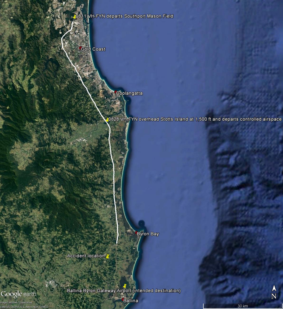
On the morning of Friday 16 June, the pilot rose at his usual time of 0500 Eastern Standard Time[2] and at about 0645 departed for the airfield. At 0737 the pilot entered the clubhouse at Southport Flying Club and spoke with the aerodrome manager and another club member. The pilot was reportedly in good spirits but reported that he had had trouble submitting his on-line flight plan. At 0800 the pilot radioed air traffic control (ATC) to submit a flight plan to Ballina. The plan was accepted and at 0811 the aircraft departed Southport Mason Field. Recorded ATC data[3] showed the aircraft climbed to an altitude of 1,500 ft above mean sea level (AMSL)[4] and turned south-east, see Figure 1. The aircraft then tracked to Stotts Island at between 1,500 and 1,800 ft. At 0828, while overhead Stotts Island, the pilot radioed ATC to report his position. This was the last radio call recorded from the pilot of FYN. At this point FYN departed controlled airspace and turned further south to track towards Ballina.
Figure 1: Radar track of VH-FYN on 16 June 2017
Radar track sourced from Airservices Australia overlaid on a Google Earth image showing the track of VH-FYN on 16 June 2017. The radar data show the aircraft take-off from Southport Masson Field and head south-east along the western VFR route to Stotts Island before tuning south towards Ballina. Also shown is the accident location approximately 13 km north-north-west of Ballina.
Source: Google Earth, modified by the ATSB
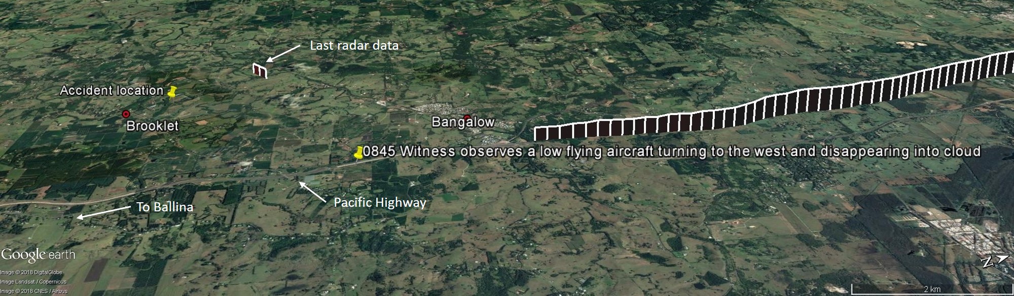
The flight from Stotts Island onwards took place between about 1,500 and 2,000 ft, tracking alongside the Pacific Highway. At 0842, when the aircraft was about 6 km north of Bangalow, a steady descent was commenced (see Figure 2).
Figure 2: Radar track of VH-FYN near Bangalow, NSW
Radar track sourced from Airservices Australia overlayed on a Google Earth image showing the track of VH-FYN on 16 June 2017. The radar data show the aircraft descended from 1,500 to 800 ft just north of Bangalow before radar identification was lost. Also shown further to the west are the last radar data obtained from VH-FYN as well as the position of the last known eyewitness of the aircraft and the location of the accident site. Source: Google Earth, modified by the ATSB
By the time the aircraft was about 1 km north of Bangalow, at 0844, it had descended to 800 ft, at which point radar identification was lost. A short time later, at approximately 0845, and about 3 km further south, a witness driving south on the Pacific Highway reported seeing an aircraft overhead in front of her vehicle. The witness noted that the aircraft was flying lower than she would normally have expected. The witness then saw the aircraft turning gradually to the right (west) and disappear into cloud. The witness reported low patchy clouds, fog and drizzle in the area at the time.
At 0847, about 6 km south-west of the end of the initial radar track, surveillance data was regained momentarily capturing three points, five seconds apart (the standard radar sample rate). These data points showed the aircraft heading in a west-south-westerly direction at an altitude of 700 ft. The elevation of terrain in this area ranged between about 88 and 233 ft.
At approximately 0850, several witnesses in the vicinity of Brooklet, NSW heard the engine noise of a low flying aircraft, followed by a loud bang. The aircraft wreckage was located on a farming property near Brooklet at an elevation of about 400 ft, 13 km north-north-west of Ballina airport. Several witnesses in the vicinity of the accident site reported low cloud and fog in the area at the time of the accident.
The pilot held a Private Pilot Licence (Aeroplane) issued under the Civil Aviation Safety Authority (CASA) Civil Aviation Regulations (CAR 5) on 29 June 1992. He then transferred his licence to Civil Aviation Safety Regulations (CASR) Part 61 on 19 February 2016. The pilot was rated for single‑engine aeroplanes and had no additional endorsements. He most recently completed a flight review in accordance with CASR Part 61 in VH-FYN (FYN) on 3 February 2016 that was valid for 24 months. The pilot’s logbook showed a total flying experience of 580 hours to the last entry dated 9 June 2017. His total experience on type was 350 hours, representing almost all of his flying experience since August 2009. In the 90 days prior to the accident, the pilot had flown 5.0 hours, all in FYN. The pilot did not hold an instrument rating and had recorded only 4.1 hours of instrument flight time, most of which was gained during training for his licence. The most recent instrument flying was recorded in August 1997.
Medical information
The pilot held a Class 2 Medical Certificate. His last medical examination was conducted on 1 December 2015 and was valid until 13 December 2017. The pilot’s Medical Certificate required him to have reading correction available while flying. The ATSB was unable to determine whether spectacles were worn or carried by the pilot at the time of the accident. The pilot was reported to have displayed normal behaviour on the morning of the flight and was said to be well rested. He was not taking any prescription medications and had no reported medical condition that might have affected his ability to operate an aircraft that day.
A post-mortem examination identified no significant background natural disease which could have contributed to the accident. Toxicological analysis concluded that the toxicology was also non‑contributory to either the accident or cause of death.
Aircraft information
Overview
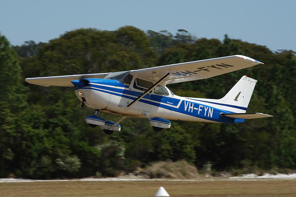
FYN (Figure 3) was a Cessna Aircraft Company 172M four-seat, single-engine, high (strut braced) wing, all metal, unpressurised, fixed (tricycle) undercarriage aircraft. The aircraft was manufactured in the United States in 1976 and first registered in Australia on 21 October 1976. The pilot had been the registered owner of the aircraft since 4 August 2009. It had current certificates of airworthiness and registration.
Figure 3: VH-FYN, taken in September 2009 at Dunwich, Queensland
FYN was maintained by a CASA-approved maintenance facility. The aircraft was VFR night certified in the private operational category and maintained under CASA CAO 100.5 – CASA schedule 5. The aircraft had a maintenance release that was valid until 17 June 2017 or 4164.3 flight hours, whichever was reached first. At the time of the accident there were nil recorded defects noted on the maintenance release nor were there any defects known by the maintenance provider. The maintenance release, which was recovered from the accident site, indicated that the aircraft had accumulated 4090.2 flight hours up to the previous flight.
Engines and propellers
The aircraft was originally fitted with a Textron Lycoming O-320-E2D with a McCauley 1C160DTM propeller. In April 2011, the aircraft was upgraded with a Textron Lycoming O-360-A4M 180 horsepower four-cylinder reciprocating engine. At the same time, a Sensenich two blade fixed pitch propeller model number 76EM8S14-0-60 was installed.
Wreckage and accident site information
Accident site
The accident site was located on the outskirts of the town of Brooklet, approximately 13 km north‑north‑west of Ballina, New South Wales (NSW). The initial impact occurred at the top of a ridge, at about 400 ft (122 m) elevation, on the border of two agricultural properties. The wreckage trail then continued for over 40 m down the side of the ridge through dense bush and rainforest. The trajectory of the wreckage trail was on a heading of about 145°.
Wreckage examination
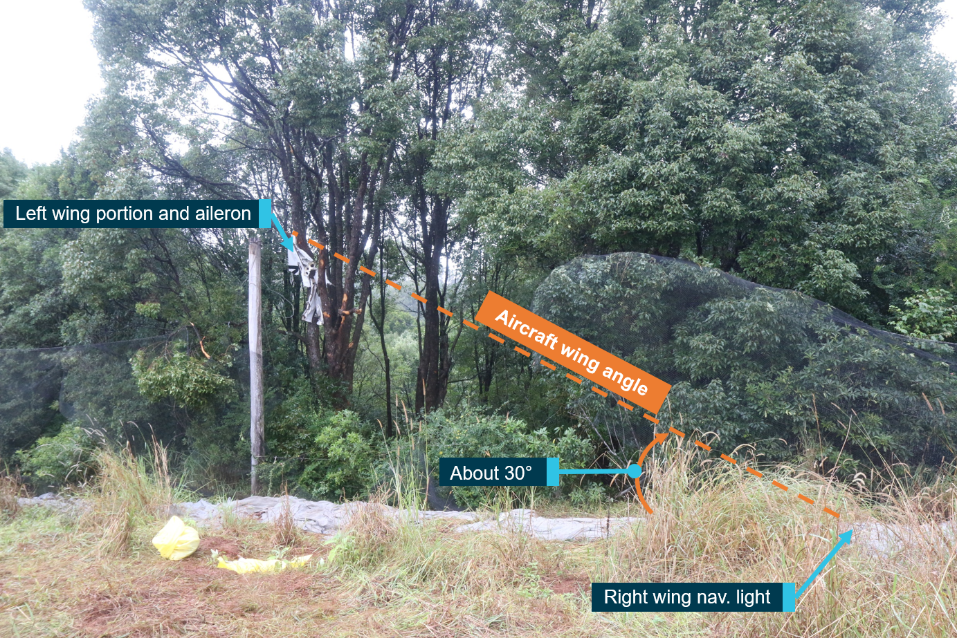
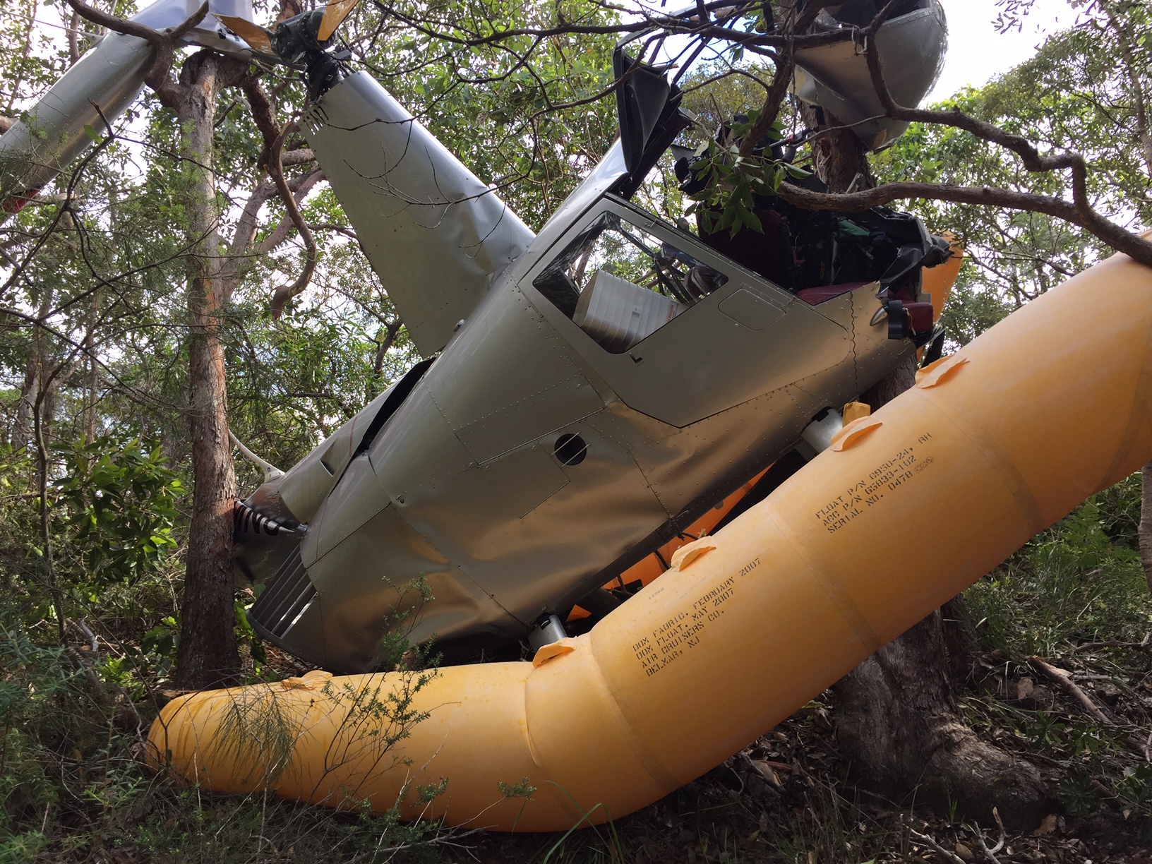
On-site examination of the wreckage found that the aircraft collided with terrain with the right wing down at an angle of about 30° (Figure 4). The outboard section of the left wing, with the left aileron and aileron bell crank was situated in a tree about six to eight meters above the ground at the beginning of the wreckage trail. The right navigation light assembly was captured on a wire that was strung along the bottom of a net at ground level. Associated with the navigation light was a ground scar consistent with the wing tip colliding with the ground. The outer points of the wings were consistent with the Cessna 172M wingspan. Measurements of tree scars at the site indicated that the wreckage trail was at about a 50° downwards trajectory, indicating that the aircraft was in a significant nose-down attitude at the time of impact.
Figure 4: Initial collision with terrain at Brooklet, New South Wales
Image shows the initial impact points of VH-FYN. The left wing impacted trees while the right wing impacted the ground, indicating an angle of bank at the time of impact of about 30° to the right.
Source: ATSB
Airframe
The bulk of the fuselage was situated approximately 25 m from the initial point of impact. The engine and propeller were a further 16 m down the slope. No evidence of either a pre or post‑impact fire was found.
Engine and propeller
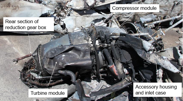
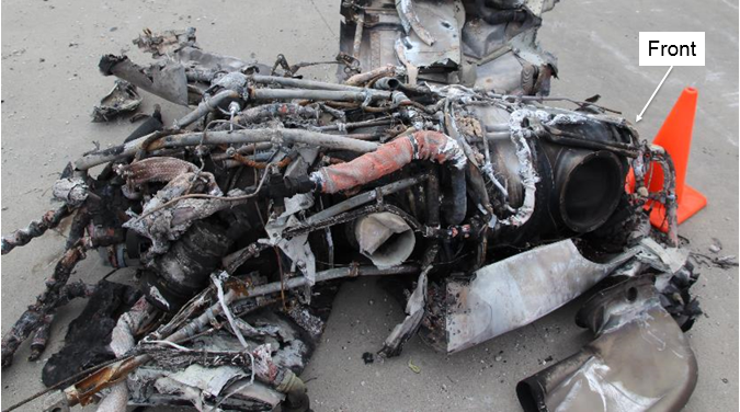
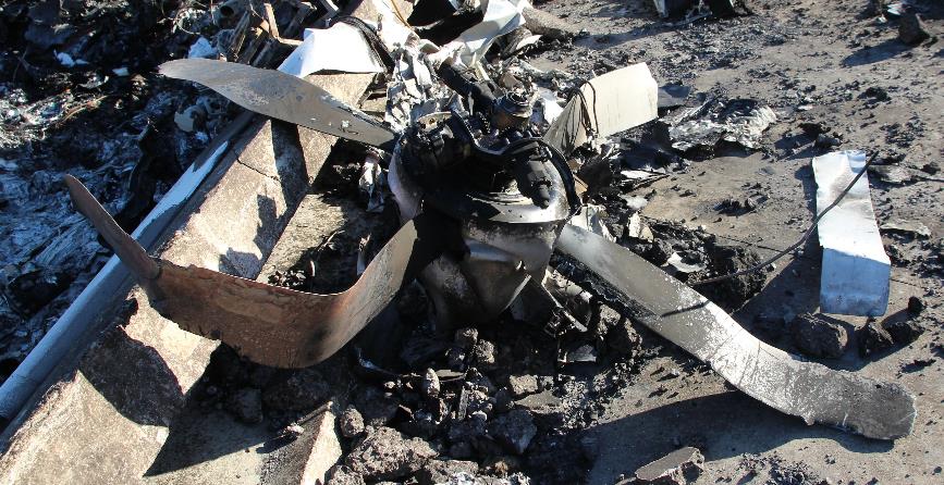
The engine and propeller assembly were found 41 m from the initial impact point. On-site examination of both the engine and propeller did not identify any mechanical defects that may have contributed to the accident. It was determined that at the time of the accident, the engine was producing significant power, which was translated through the propeller.
Flight controls
All primary and secondary flight control surfaces were identified in the wreckage trail. Additionally, all control cables were attached to either the appropriate control surface, or control mechanism. Cables that were fractured were identified as failing due to overstress, consistent with impact forces.
Weight and balance
The on-site examination found a small amount of cargo, which was stowed in the rear part of the fuselage and secured with a cargo net. The amount of cargo was not significant enough to have adversely affected the centre of gravity of the aircraft.
Fuel
Ten days prior to the accident, on 6 June 2017, fuel records show that that the pilot fuelled his aircraft with 64.84 litres of Avgas at Southport Flying Club. It is unknown if this amount filled the aircraft to its capacity of 42 US gallons (approximately 160 litres). There were two flights between 6 and 16 June 2017 (the date of the accident), totalling 1.2 flight hours. Dependant on throttle settings and altitude, the fuel burn rate of a standard Cessna 172M is about 8 US gallons per hour, or about 30 litres per hour. However, it would be slightly higher with the O-360 engine installed.
Although a fuel sample was not available at the accident site due to the significant disruption of the aircraft, investigators identified a strong smell of fuel at the accident site. Additionally, several witnesses reported hearing the sound of the engine up until the point of impact, indicating there was fuel on board the aircraft at the time of the accident.
Flight instruments
All instruments were identified in the main portion of the wreckage. A number of flight instruments, including the artificial horizon, altimeter, airspeed indicator, vertical speed indicator, directional gyroscope and the turn co-ordinator were retrieved from the accident site for further examination at the ATSB’s technical facilities in Canberra. The subsequent examinations did not find evidence to support a failure of any of these instruments prior to impact.
The vacuum supply line to the artificial horizon and directional gyroscope was found to have cracks in the outer sheath of the hose. The hose was retrieved from the site for further examination. Testing of the hose indicated that the cracking was superficial and did not affect the capacity of the hose to maintain the vacuum required to operate the instruments.
Meteorological information
Bureau of Meteorology forecasts
The flight from Southport to Ballina overlapped two forecast areas. [5] The flight originated in Area 40, which covers the area from just north of Rockhampton to just south of the Gold Coast. The destination, Ballina, is in Area 20, which covers the area from just south of the Gold Coast down to Lake Macquarie. Details of these forecast areas can be found on the Airservices Australia’s Planning Chart Australia (PCA).
Sections of the area forecast (ARFOR) for Area 40, which was valid from 0300 to 1800 on 16 June 2017, that potentially affected the flight included:
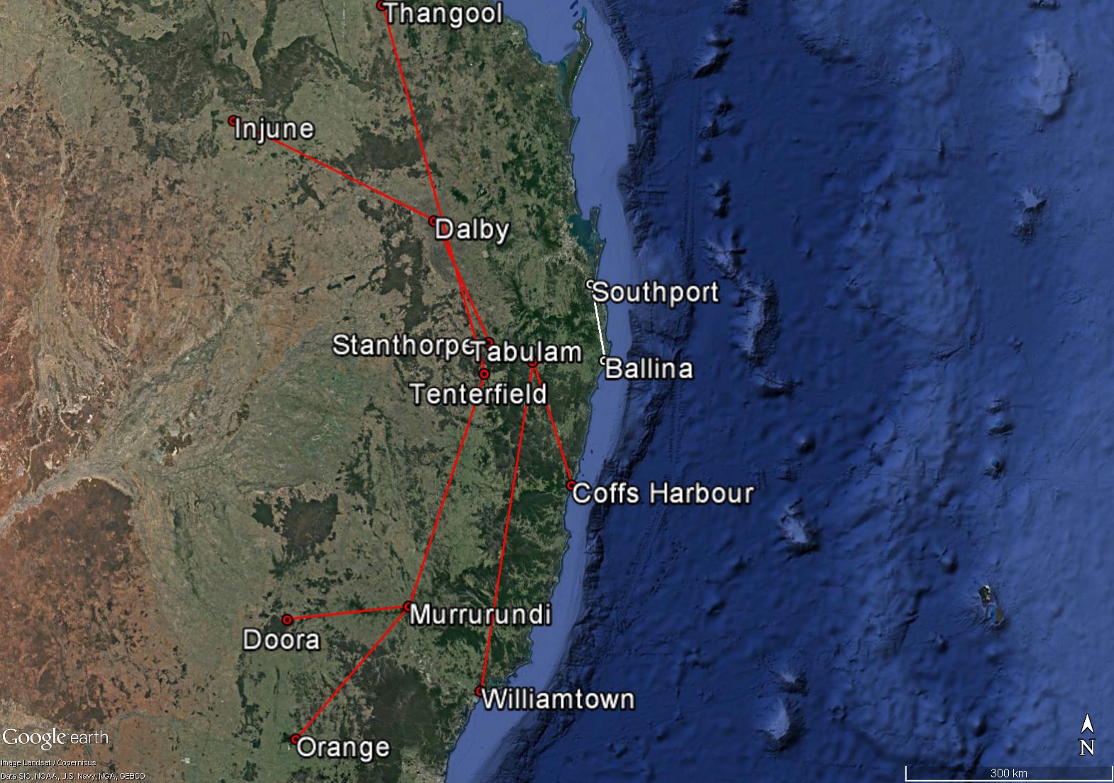
Areas of broken low cloud east of Thangool - Tenterfield until 1100 (see Figure 5).
Broken stratus clouds between 500 and 2,500 ft near precipitation
Scattered cumulus and stratus clouds between 2,500 and 8,000 ft east of Injune – Dalby - Stanthorpe
Significant weather in Area 40 was forecast as being fog, mist, showers of rain and smoke. Visibility was forecast to be 500 m in fog, 2,000 m in mist and thick smoke, 3,000 m in showers of rain and 8 km in smoke haze. The freezing level was above 10,000 ft and icing was forecast to be moderate in cloud above the freezing level. Turbulence was forecast to be moderate in cumulus clouds.
The amended ARFOR for Area 20 was valid from 0730 to 1500 on 16 June 2017. It forecast:
Scattered fog and mist on land south east of Tenterfield – Murrurundi - Doora until 0900, with isolated fog and mist on the remainder of land in area 20 until 1100.
Broken low cloud on the ranges and slopes east of Tenterfield – Murrurundi - Orange until 1200, contracting to the ranges northeast of Tabulam – Coffs Harbour.
Broken low cloud in precipitation as well as isolated showers on land east of Tabulam - Williamtown and scattered showers at sea.
Broken stratus clouds between 1,000 ft and 2,500 ft at sea and on the coast in precipitation.
Broken stratus clouds between 2,000 ft to 5,000 ft on the ranges and slopes east of Tenterfield –Murrurundi - Orange until 1200, then contracting to the ranges northeast of Tabulam - Coffs Harbour.
Broken cumulus and stratus clouds between 2,000 ft and 10,000 ft at sea and on the coast, with cloud tops above 10,000 ft at sea after 1200.
Significant weather in area 20 was forecast as being fog, mist and showers of rain. Visibility was forecast to be 300 m in fog, 2,000 m in mist and 4,000 m in showers of rain. The freezing level was above 10,000 ft, tending to 9,000 ft south of Murrurundi after 0900 with no significant icing conditions forecast. Turbulence was forecast to be moderate in cumulus clouds.
Figure 5: Figure showing the accident flight in relation to waypoint references given in the Area 20 and 40 forecasts. Boundaries given by the Area forecast are shown in red; the location of the flight path is shown in white.
Google Earth image showing waypoint locations given on the Area 20 and Area 40 forecasts in relation to the accident flight Source: Google Earth, modified by the ATSB
In addition to the area forecasts, the Bureau of Meteorology also provided a terminal forecast (TAF)[6] for Ballina. The Ballina TAF, issued at 0300 on 16 June 2017 was valid between 0600 and 1600. The TAF forecast 8 kt winds from 200°, visibility greater than 10 km and showers of rain. Cloud was forecast to be scattered with a base of 2,000 ft above the aerodrome and broken with a base 3,500 ft above the aerodrome. It was forecast that there would be intermittent periods (less than 30 minutes) between 0600 and 1600 where visibility would drop to 4,000 m there would be showers of rain, and broken cloud with a base of 1,000 ft above the aerodrome. The conditions forecast on the Lismore TAF were broadly consistent with the conditions at Ballina. The exception being the addition of a forecast 30 per cent probability of deteriorations of one hour or more with visibility to 4,000 m, mist, and scattered cloud with a base at 500 ft above the aerodrome, between 0800 and 1000 on 16 June.
Bureau of Meteorology observations
The Ballina Automatic Weather Station (AWS) recorded that at 0900 on the day of the accident, the wind at Ballina Airport was from the south-west at an average speed of 13 km/h, the temperature was 17.6 °C, the relative humidity was 95 per cent, the mean sea level pressure was 1024.5 hPa and cloud covered 8 oktas[7] of sky.
Witness observations of weather
The weather conditions at Southport on the morning of 16 June 2017 were reported by several witnesses to be clear and fine, with no rain or significant wind or cloud cover. In contrast, the maintenance provider described the conditions at Ballina on the morning of 16 June as ‘amongst some of the worst weather I had seen. There was very heavy rain, low cloud and very poor visibility’.
The last known eyewitness of FYN flying just south of Bangalow described the conditions as being ‘low patchy clouds, fog and drizzly rain’, and visibility that was ‘fairly low’. Witnesses in Brooklet at the time of the accident described the conditions in the vicinity of the accident site as ‘overcast with fairly low cloud’, with a ‘ceiling of about 200 ft.’ Other witnesses described ‘very low fog and cloud, there may have been some drizzle but it wasn’t raining.’
Pilot access to weather information
The pilot was reported to be diligent with checking weather conditions on a regular basis. He had an Airservices Australia National Aeronautical Information Processing System (NAIPS) account, which he accessed through the OzRunways electronic flight bag application. The NAIPS account provides meteorological information, Notice to Airmen (NOTAM), as well as briefing information. The pilot accessed his NAIPS account (though OzRunways) a number of times in the week leading up to the day of the accident. The last successful NAIPS logon was at 1703 on Thursday, 15 June 2017 (the evening before the accident flight), during which a location briefing was requested. The location briefing consisted of an Area 20 forecast valid from 1400 on 15 June to 0300 on 16 June 2017. A number of unsuccessful login attempts were made later that evening, between 2030 and 2037.
On the morning of the accident, the pilot reported that the weather was fine. Although there are no NAIPS logins reordered on that morning, it is possible that weather information was obtained from other sources. Upon reaching the Southport Flying Club, the pilot reported to other members that he had trouble submitting his flight plan, as he could not log in. At 0800, the pilot submitted his flight plan to ATC by radio.
Additional information
Visual Flight Rules
The CASA Visual Flight Rules Guide outlined that flight under the visual flight rules (VFR) can only be conducted in Visual Meteorological Conditions (VMC).[8] Additionally, when operating at or below 2,000 ft above the ground or water, the pilot must be able to navigate by visual reference to the ground or water.
The majority of the flight, and the location of the accident, were in (uncontrolled) Class G airspace. The following conditions were stipulated for flight under the VFR in Class G airspace when below 10,000 ft and above 3,000 ft AMSL or 1,000 ft above ground level (whichever is higher):
a flight visibility of 5,000 m
a minimum vertical distance of 1,000 ft and horizontal distance of 1,500 m from cloud.
In the case of aeroplane operations in Class G at or below 3,000 ft AMSL or 1,000 ft above ground level (whichever is higher), the following minimum conditions were stipulated:
a flight visibility of 5,000 m
that the aeroplane shall be maintained clear of cloud and in sight of the ground or water
Risks of flying in areas of reduced visual cues
The safety risks of VFR pilots flying from VMC conditions into instrument meteorological conditions (IMC) are well documented. This has been the focus of numerous ATSB reports and publications, as VFR pilots flying into IMC represents a significant cause of aircraft accidents and fatalities. In 2013 the ATSB Avoidable Accidents series was re-published. Of these publications, the booklet titled Accidents involving pilots in Instrument Meteorological Conditions outlined that:
In the 5 years 2006–2010, there were 72 occurrences of visual flight rules (VFR) pilots flying in instrument meteorological conditions (IMC) reported to the ATSB…About one in ten VFR into IMC events result in a fatal outcome.
Additionally, a study conducted by the United States National Transportation Safety Board (NTSB, 2005) found that ‘reduced-visibility weather represents a particularly high risk to [general aviation] operations’ and that ‘weather may…test the limits of pilot knowledge, training, and skill to the point that underlying issues are identified.’
The NTSB study also outlined that historically, about two-thirds of all general aviation (GA) accidents that occur in IMC are fatal; a rate much higher than the overall fatality rate for GA accidents. A study by Newman (2007) conducted for the ATSB titled An overview of spatial disorientation as a factor in aviation accidents and incidents outlined that there was a four times greater chance of fatality in a VFR flight into IMC accident than any other sort of accident (quoting Batt & O’Hare, 2005 and NTSB, 1989).
Spatial disorientation
Spatial disorientation is a type of loss of situation awareness, and is different to geographical disorientation, or incorrectly perceiving the aircraft’s distance or bearing from a fixed location. Spatial disorientation occurs when pilots do not correctly sense their aircraft’s attitude, airspeed or altitude in relation to the earth’s surface. In terms of an aircraft’s attitude, spatial disorientation is often described simply as the inability to determine ‘which way is up’, although the effects can often be more subtle than implied by that description.
Spatial disorientation occurs when the brain receives conflicting or ambiguous information from the sensory systems. It is likely to happen in conditions in which visual cues are poor or absent, such as in adverse weather or at night.[9] Spatial disorientation presents a danger to pilots, as the resulting confusion can often lead to incorrect control inputs and resultant loss of aircraft control.
Research on spatial disorientation indicates that, for pilots who are not instrument rated, loss of control will likely occur between about 60 seconds (Benson, 1988 in Gibb, Gray and Scharff, 2010) and 178 seconds on average (Bryan, Stonecipher, & Aron, 1954) after the loss of visual reference. These studies led to the FAA’s and CASA’s ‘178 seconds to live’ educational campaigns. Gibb, Gray and Scharff (2010) also state that ‘spatial disorientation accidents have fatality rates of 90–91 percent, which indicates how compelling the misperceptions can be.’
Related occurrences
There have been a number of accidents relating to VFR pilots flying into reduced visibility conditions. Many of these occurrences have been summarised in the research reports previously mentioned (B2005/0127 and AR-2011-050) as well as in ATSB accident reports (for example, ‑AO2015-131 and AO-2016-006). Of particular interest are those occurrences where pilots have avoided an accident outcome by seeking assistance from other aircraft or from ATC. Of note is a similar occurrence that happened on the same day and in the same location as the accident involving FYN, but with a very different outcome. See below for details.
ATSB occurrence 201702740
On 16 June 2017, the pilot of a light aircraft was flying under VFR from Taree, NSW, to Southport, Queensland. While near Ballina, NSW the weather suddenly deteriorated and the pilot attempted to turn back to land at Coffs Harbor, NSW. However, the weather continued to close in, at which point the pilot reported to ATC that he was now flying in instrument meteorological conditions (IMC). ATC observed a sporadic radar return in the position described by the pilot and advised that the pilot gain altitude, which assisted with radar identification. ATC then guided the aircraft to Evans Head, NSW where the weather had cleared sufficiently for the aircraft to land safely.
While en route from Southport, Queensland to Ballina, New South Wales, Cessna Aircraft Corporation 172M, registered VH-FYN (FYN), entered an area of low visibility near the town of Bangalow, New South Wales. The aircraft began a descent just north of Bangalow before deviating off course and heading inland. The aircraft was last witnessed at low altitude about 2 km south of Bangalow disappearing into cloud in an area of low cloud, fog and drizzle. A short time later the aircraft collided with terrain on an agricultural property about 13 km north-north-west of Ballina.
There were no defects or anomalies found with the recovered components of the aircraft that might have contributed to the accident. Additionally, a review of the pilot’s medical records, post‑mortem and toxicology results indicated that it was unlikely that the pilot became incapacitated during the flight. Therefore, this analysis will focus on the examination of the factors that led to a visual flight rules (VFR) pilot losing control of his aircraft in an area of reduced visibility.
Decision to depart Southport
The reason for the flight on 16 June 2017 was to deliver the aircraft to a maintenance facility, as the aircraft’s maintenance release was due to expire the following day. The pilot initially had the aircraft maintenance booked for Tuesday 13 June 2017. The pilot then rescheduled the booking twice that week based on the forecast weather conditions. The final booking was scheduled for Friday 16 June 2017. During the course of that week, the pilot had downloaded weather forecasts through his National Aeronautical Information Processing System (NAIPS) account a number of times. Additionally, the pilot had been in contact with the maintenance provider in Ballina to check the weather conditions and reschedule the bookings. The last call the pilot made to the maintenance provider was on Wednesday 14 June 2017. During that call, the maintenance provider told the pilot he could get a special flight permit to allow him to fly the aircraft to Ballina after the expiration of the maintenance release. Instead, the pilot confirmed the booking for Friday.
On the morning of the accident, the weather in Southport appeared fine. The pilot did not call ahead to the maintenance provider to check the weather conditions in Ballina. Due to difficulties logging into his account, the pilot did not access his NAIPS account to download a weather briefing. It is possible that the pilot accessed a weather forecast for Ballina through other means, however it could not be determined if that was done.
Neither the Area 20 forecast nor the Ballina Aerodrome Forecast (TAF) precluded a visual flight rules (VFR) flight from Southport to Ballina on the day of the accident. Both forecasts, however, indicated the possibility of encountering areas of fog, cloud and rain, in which visibility would reduce below that required for VFR flight. Additionally, the Ballina TAF intermittent (INTER) conditions indicated that for multiple periods of up to 30 minutes duration, the visibility at the aerodrome would be below that required for landing under the VFR. Although the planned flight from Southport to Ballina would have been possible under the VFR, the forecast conditions would have necessitated planning for an alternate landing point and/or being prepared to hold at Ballina during the INTER periods. Additional fuel would have been required to account for these diversions and holding time. It is unknown if these factors were taken into account by the pilot in his pre-flight planning but they were not mentioned in the verbal flight plan he lodged with Airservices Australia 11 minutes before taking off.
Development of the accident
Flying into area of reduced visibility
The majority of the flight south from Stotts Island was conducted between about 1,500 and 2,000 ft. Approximately 6 km north of Bangalow the aircraft began a steady decent. At 800 ft radar identification was lost. Given the witness descriptions of the weather conditions in this area, it is possible that the pilot initiated this descent to stay below cloud to maintain his visual reference to the ground, in accordance with the VFR requirements.
The last known eyewitness observed FYN at a low altitude about 2 km south of Bangalow at about 0845. The witness saw the aircraft enter into cloud in an area of low cloud, fog and drizzle as the aircraft turned inland, to the west. Additionally, the last radar data showed the aircraft tracking in a west-south-westerly direction about 5 km to the west of the planned track.
From the information available, it could not be determined why the pilot altered his heading and continued 5 km off the planned track to Ballina. It is possible that the pilot inadvertently followed the road to Lismore or attempted to turn back towards the north, but became disorientated. It is also possible that the pilot was intentionally attempting to divert to Lismore (about 30 km to the west of Ballina). The last three radar data points show the aircraft heading at about 240°. This heading, if continued, would track the aircraft to Lismore airport. Additionally, the location of the turn to the west is roughly consistent with the location of the road turn-off to Lismore (Bangalow road). If the pilot did intend on diverting to Lismore, he could have used Bangalow road to navigate there as the last three radar data show the aircraft in close proximity to Bangalow road. However, the radar data at this location only covers 10 seconds of flight and it difficult to infer the intentions of the pilot with such little data. In addition, diversion aerodromes were not mentioned in the pilot’s verbal flight plan submission and the Lismore TAF indicated that conditions at Lismore were probably no better than Ballina. It is not known, however, if the pilot had access to either the Ballina or Lismore TAFs.
En route decision making
The maintenance release for the aircraft was due to expire the day after the accident and the maintenance booking was rescheduled twice that week due to inclement weather conditions at Ballina. The maintenance provider had told the pilot he could apply for a special flight permit after the expiration of the maintenance release. Despite this, it is likely the pilot was under a degree of self-imposed pressure to continue to Ballina to conduct the maintenance inspection before it expired. Although it could not be determined what decisions the pilot made en route, an earlier decision to divert or return to Southport may have avoided flight into areas of reduced visibility.
Spatial disorientation resulting from a loss of visual cues
There was approximately five minutes between the last known sighting of FYN and the time of impact. The aircraft was last seen disappearing into cloud in an area of reduced visibility. The area in the vicinity of the accident site was also reported by a number of witnesses to have low cloud, fog, drizzle and reduced visibility. It is therefore likely that for most, if not all of the last five minutes of flight, FYN was flying in conditions of reduced visibility. The pilot of FYN did not hold an instrument rating and had logged only 4.6 hours of instrument flying, the most recent being in 1996.
Examination of the accident site found that at the time of impact, the aircraft was in a 30° right wing down and significant nose down attitude. This attitude is not consistent with normal operations of a C172, and is indicative of a loss of control. It is therefore likely that within five minutes of flying into conditions of reduced visibly, without adequate visual reference to the horizon, the pilot of FYN became spatially disorientated leading to a loss of control and collision with terrain.
Findings
From the evidence available, the following findings are made with respect to the collision with terrain involving Cessna 172, VH-FYN 13 km north-north-west of Ballina, NSW, on 16 June 2017. These findings should not be read as apportioning blame or liability to any particular organisation or individual.
Contributing factors
The pilot departed Southport, Queensland for Ballina, New South Wales under the Visual Flight Rules with a forecast likelihood of low cloud, fog and showers of rain that reduced conditions below that required for visual flight.
It is likely the pilot encountered conditions of reduced visual cues and became spatially disorientated which led to a loss of control and collision with terrain.
Sources and submissions
Sources of information
The sources of information during the investigation included the:
Groff L.S. & Price J.M. General aviation accidents in degraded visibility: a case control study of 72 accidents. Aviat Space Environ Med 2006; 77:1062–1067.
Gibb, R., Gray, R. & Sharff, L. Aviation Visual Perception: Research, Misperception and Mishaps. Ashgate, 2010.
Bryan, L.A., Stonecipher, J. W. & Aron, K. 180-degree turn experiment. University of Illinois Bulletin Volume 52, Number 11. September 1954.
Submissions
Under Part 4, Division 2 (Investigation Reports), Section 26 of the Transport Safety Investigation Act 2003 (the Act), the Australian Transport Safety Bureau (ATSB) may provide a draft report, on a confidential basis, to any person whom the ATSB considers appropriate. Section 26 (1) (a) of the Act allows a person receiving a draft report to make submissions to the ATSB about the draft report.
A draft of this report was provided to CASA and the family of the pilot.
Submissions were received from both parties. The submissions were reviewed and where considered appropriate, the text of the report was amended accordingly.
Purpose of safety investigations
The objective of a safety investigation is to enhance transport safety. This is done through:
identifying safety issues and facilitating safety action to address those issues
providing information about occurrences and their associated safety factors to facilitate learning within the transport industry.
It is not a function of the ATSB to apportion blame or provide a means for determining liability. At the same time, an investigation report must include factual material of sufficient weight to support the analysis and findings. At all times the ATSB endeavours to balance the use of material that could imply adverse comment with the need to properly explain what happened, and why, in a fair and unbiased manner. The ATSB does not investigate for the purpose of taking administrative, regulatory or criminal action.
Terminology
An explanation of terminology used in ATSB investigation reports is available here. This includes terms such as occurrence, contributing factor, other factor that increased risk, and safety issue.
Publishing information
Released in accordance with section 25 of the Transport Safety Investigation Act 2003
Ownership of intellectual property rights in this publication
Unless otherwise noted, copyright (and any other intellectual property rights, if any) in this report publication is owned by the Commonwealth of Australia.
Creative Commons licence
With the exception of the Coat of Arms, ATSB logo, and photos and graphics in which a third party holds copyright, this publication is licensed under a Creative Commons Attribution 3.0 Australia licence.
Creative Commons Attribution 3.0 Australia Licence is a standard form licence agreement that allows you to copy, distribute, transmit and adapt this publication provided that you attribute the work.
The ATSB’s preference is that you attribute this publication (and any material sourced from it) using the following wording: Source: Australian Transport Safety Bureau
Copyright in material obtained from other agencies, private individuals or organisations, belongs to those agencies, individuals or organisations. Where you wish to use their material, you will need to contact them directly.
On 30 May 2017, a twin‑engine Cessna 441 Conquest II (Cessna 441), registered VH-XMJ and operated by AE Charter (trading as Rossair) departed Adelaide Airport, South Australia for a return flight via Renmark Airport, South Australia.
On board the aircraft were:
an inductee pilot undergoing a proficiency check, flying from the front left control seat
the chief pilot conducting the proficiency check, and under assessment for the company training and checking role for Cessna 441 aircraft, seated in the front right control seat
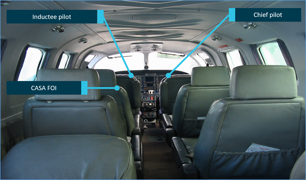
a Civil Aviation Safety Authority (CASA) flying operations inspector, observing and assessing the flight from the first passenger seat directly behind the inductee pilot.
Each pilot was qualified to operate the aircraft.
The flight departed Adelaide at about 1524 local time and flew to the Renmark area for exercises related to the check flight, followed by a landing at Renmark Airport. After a short period of time running on the ground, the aircraft departed from runway 25 at about 1614.
A distress beacon broadcast was subsequently received by the Joint Rescue Coordination Centre and passed on to air traffic services at 1625. Following an air and ground search the aircraft was located by a ground party at 1856 about 4 km west of Renmark Airport. All on board were fatally injured and the aircraft was destroyed.
What the ATSB found
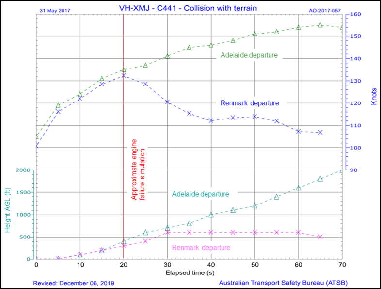
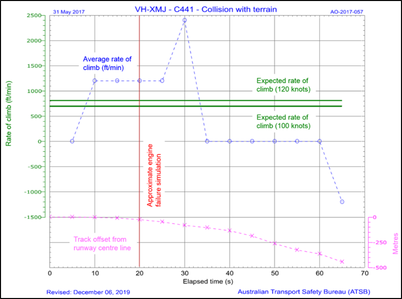
The ATSB determined that, following a simulated failure of one of the aircraft’s engines at about 400 ft above the ground during the take‑off from Renmark, the aircraft did not achieve the expected single engine climb performance or target airspeed. As there were no technical defects identified, it is likely that the reduced aircraft performance was due to the method of simulating the engine failure, pilot control inputs or a combination of both.
It was also identified that normal power on both engines was not restored when the expected single engine performance and target airspeed were not attained. That was probably because the degraded aircraft performance, or the associated risk, were not recognised by the pilots occupying the control seats. Consequently, about 40 seconds after initiation of the simulated engine failure, the aircraft experienced an asymmetric loss of control.
The single engine failure after take‑off exercise was conducted at a significantly lower height above the ground than the 5,000 ft recommended in the Cessna 441 pilot’s operating handbook. This meant that there was insufficient height to recover from the loss of control before the aircraft impacted the ground.
While not necessarily contributory to the accident, the ATSB also identified that:
The operator’s training and checking manual procedure for simulating an engine failure in a turboprop aircraft was inappropriate and increased the risk of asymmetric control loss.
The CASA flying operations inspector was not in a control seat and was unable to share the headset system used by the inductee and chief pilot. Therefore, despite having significant experience in Cessna 441 operations, he had reduced ability to actively monitor the flight and communicate any identified problem.
The inductee and chief pilot, while compliant with recency requirements, had limited recent experience in the Cessna 441 and that probably led to a degradation in the skills required to safely perform and monitor the simulated engine failure exercise.
The chief pilot and other key operational managers within Rossair were experiencing high levels of workload and pressure during the months leading up to the accident.
The Civil Aviation Safety Authority’s method of oversighting Rossair in the several years prior to the accident increased the risk that organisational issues would not be identified and addressed.
Finally, a lack of recorded data from this aircraft reduced the available evidence about pilot handling aspects and cockpit communications. This limited the extent to which potential factors contributing to the accident could be analysed.
What's been done as a result
Following the accident, CASA issued a temporary management instruction to provide higher risk protection around operations involving CASA flying operations inspectors. However, at the time of writing these instructions had not been permanently incorporated into regulation.
Safety message
Conducting a simulated engine failure after an actual take-off is a high-risk exercise with little margin for error. For that reason, Cessna recommended practicing this sequence in the 441 aircraft at a height of 5,000 ft above ground level to allow the opportunity for recovery in the event that control is lost.
A review of past accidents indicates that, while accidents associated with engine malfunctions are rare, training to manage one engine inoperative flight (OEI) after take‑off is important. The ATSB recommends that such training should follow the manufacturer’s guidance and, if possible, be conducted in an aircraft simulator. If the sequence is conducted in the aircraft close to the ground, then effective risk controls need to be in place to prevent a loss of control as recovery at low height will probably not be possible. Such defences include:
defined OEI performance criteria that, if not met, require immediate restoration of normal power
use of the appropriate handling techniques to correctly simulate the engine failure and ensure that aircraft drag is minimised/OEI performance is maximised
ensuring that the involved pilots have the appropriate recency and skill to conduct the exercise and that any detrimental external factors, such as high workload or pressure, are minimised.
The occurrence
What happened
On 30 May 2017, a Cessna 441 Conquest II (Cessna 441), registered VH-XMJ (XMJ) and operated by AE Charter, trading as Rossair, departed Adelaide Airport, South Australia for a return flight via Renmark Airport, South Australia.
On board the aircraft were:
an inductee pilot undergoing a proficiency check, flying from the front left control seat
the chief pilot conducting the proficiency check, and under assessment for the company training and checking role for Cessna 441 aircraft, seated in the front right control seat
a Civil Aviation Safety Authority flying operations inspector (FOI), observing and assessing the flight from the first passenger seat directly behind the left hand pilot seat.
Each pilot was qualified to operate the aircraft.
There were two purposes for the flight. The primary purpose was for the FOI to observe the chief pilot conducting an operational proficiency check (OPC), for the purposes of issuing him with a check pilot approval on the company’s Cessna 441 aircraft. The second purpose was for the inductee pilot, who had worked for Rossair previously, to complete an OPC as part of his return to line operations for the company.
The three pilots reportedly started their pre‑flight briefing at around 1300 Central Standard Time.[1] There were two parts of the briefing – the FOI’s briefing to the chief pilot, and the chief pilot’s briefing to the inductee pilot. As the FOI was not occupying a control seat, he was monitoring and assessing the performance of the chief pilot in the conduct of the OPC.
There were two distinct exercises listed for the flight (see the section titled Check flight sequences). Flight exercise 1 detailed that the inductee pilot was to conduct an instrument departure from Adelaide Airport, holding pattern and single engine RNAV[2] approach, go around and landing at Renmark Airport. Flight exercise 2 included a normal take‑off from Renmark Airport, simulated engine failure after take-off, and a two engine instrument approach on return to Adelaide.
The aircraft departed from Adelaide at 1524, climbed to an altitude about 17,000 ft above mean sea level, and was cleared by air traffic control (ATC) to track to waypoint RENWB, which was the commencement of the Renmark runway 07[3] RNAV-Z GNSS approach. The pilot of XMJ was then cleared to descend, and notified ATC that they intended to carry out airwork in the Renmark area. The pilot further advised that they would call ATC again on the completion of the airwork, or at the latest by 1615. No further transmissions from XMJ were recorded on the area frequency and the aircraft left surveillance coverage as it descended towards waypoint RENWB.
The common traffic advisory frequency used for air-to-air communications in the vicinity of Renmark Airport recorded several further transmissions from XMJ as the crew conducted practice holding patterns, and a practice runway 07 RNAV GNSS approach. Voice analysis confirmed that the inductee pilot made the radio transmissions, as expected for the check flight. At the completion of the approach, the aircraft circled for the opposite runway and landed on runway 25, before backtracking and lining up for departure. That sequence varied from the planned exercise in that no single-engine go-around was conducted prior to landing at Renmark.
At 1614, the common traffic advisory frequency recorded a transmission from the pilot of XMJ stating that they would shortly depart Renmark using runway 25 to conduct further airwork in the circuit area of the runway. A witness at the airport reported that, prior to the take‑off roll, the aircraft was briefly held stationary in the lined‑up position with the engines operating at significant power. The take-off roll was described as normal however, and the witness looked away before the aircraft became airborne.
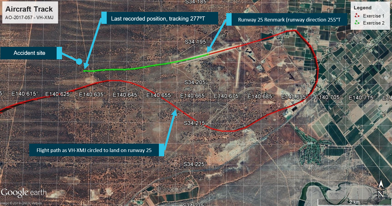
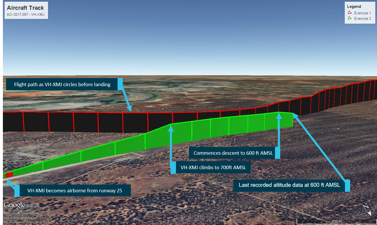
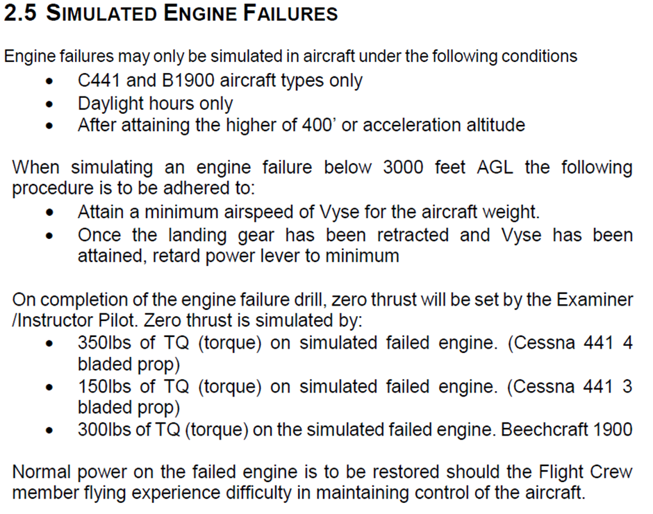
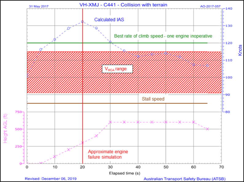
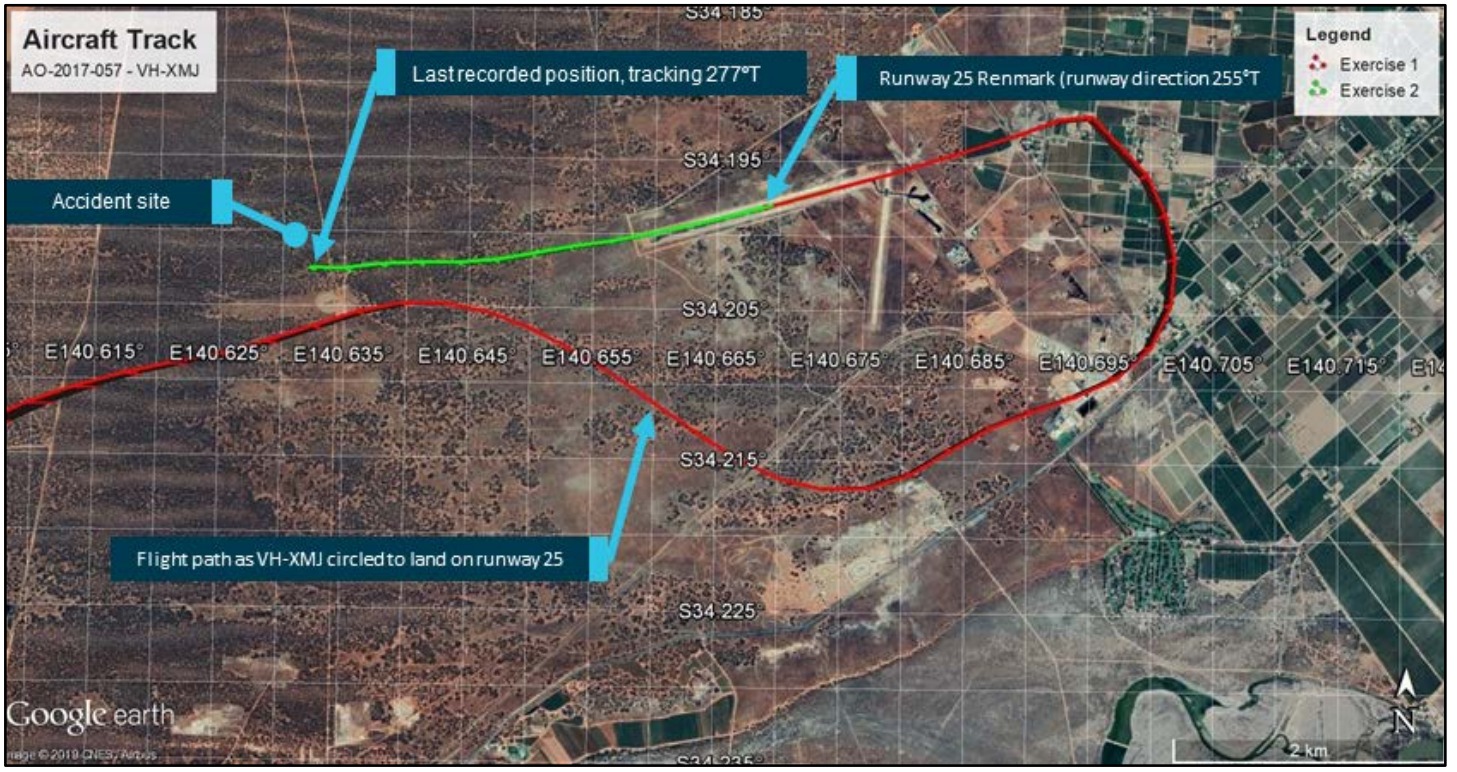
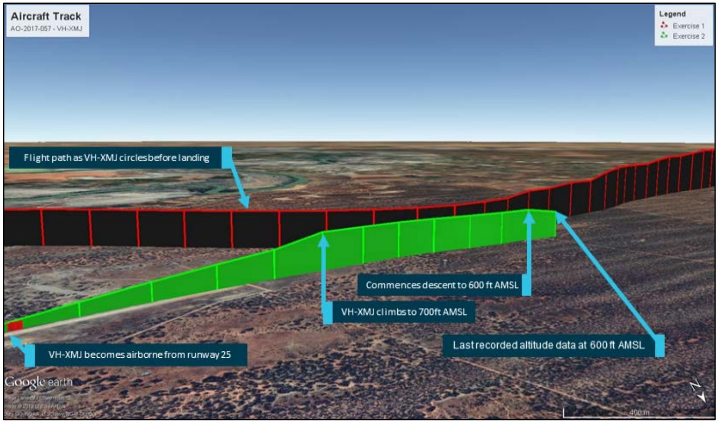
The aircraft maintained the runway heading until reaching a height of between 300‑400 ft above the ground (see the section titled Recorded flight data). At that point the aircraft began veering to the right of the extended runway centreline (Figures 1 and 15). The aircraft continued to climb to about 600 ft above the ground (700 ft altitude), and held this height for about 30 seconds, followed by a descent to about 500 ft (Figures 2 and 13). The information ceased 5 seconds later, which was about 60 seconds after take-off.
Figure 1: Position information of VH-XMJ as the aircraft circled and landed on runway 25 (depicted in red), before backtracking and departing (depicted in green).
Source: Google and OzRunways, annotated by the ATSB
Figure 2: Altitude information of VH-XMJ (each vertical line represents 5 seconds)
Source: Google and OzRunways, annotated by the ATSB
A distress beacon broadcast was received by the Joint Rescue Coordination Centre and passed on to ATC at 1625. Following an air and ground search the aircraft was located by a ground party at 1856 about 4 km west of Renmark Airport. All on board were fatally injured and the aircraft was destroyed.
There were three pilots on board VH-XMJ (XMJ). A summary of the role of each pilot, and their relevant training, qualifications and experience is provided below. The intention of the flight was to allow a Civil Aviation Safety Authority (CASA) flying operations inspector (FOI) to observe the Rossair chief pilot conduct an operator proficiency check (OPC), for the purposes of issuing him with a Conquest II (Cessna 441) check pilot approval (see the section titled Check pilot training). The pilot undertaking the OPC was being inducted into the company. The inductee pilot was seated in the left-hand control seat, the chief pilot in the right-hand control seat, and the CASA FOI in the first row passenger seat behind the left-hand seat pilot.
Inductee pilot
Flight role
The inductee pilot was the planned pilot flying. He was an experienced Cessna 441 pilot who had previously flown for Rossair from May 2010 to August 2014. Undertaking the OPC was part of his induction back into the company.
Qualifications and experience
The inductee pilot held an Air Transport Pilot (Aeroplane) Licence (ATPL), issued in December 1991, and Commercial Pilot (Aeroplane) Licence (CPL) issued in January 1979. He also held an ATPL from the Netherlands. He held a current class 1 aviation medical certificate (valid to 24 June 2017), which required reading correction to be available when flying, but placed no other restrictions on operation.
The pilot’s logbook showed a total flying experience of 14,751.1 hours, with 3,293.7 hours on single engine aircraft and 11,427.4 hours on a range of type-rated and class-rated multi-engine aircraft (see the section titled Pilot licencing). This included 987.7 hours on Cessna 441 aircraft. With the exception of the accident flight and an associated practice flight the week before, all of the inductee pilot’s Cessna 441 experience was gained prior to August 2014.
A review of the pilot’s licence and associated documentation identified that he held the relevant endorsements and ratings to fly the Cessna 441. In addition, he held a current grade 1 instructor rating for multi‑engine class rating training.
In the previous 90 days, the inductee pilot had logged 22.2 hours flying as pilot in command, all on multi-engine class rated aircraft, including 3.5 hours in XMJ the week prior to the accident.
Proficiency checks and flight reviews
The inductee pilot last completed an instrument rating proficiency check (IPC) during his multi‑engine class aircraft flight review in a Beechcraft Baron 95-B55 on 13 February 2017. This check required the pilot to demonstrate conducting a one-engine inoperative instrument departure, which was marked on his proficiency check form as completed satisfactorily. His IPC was valid at the time of the accident.
Chief pilot
Flight role
The pilot in the right-hand seat was appointed as the Rossair chief pilot in January 2016. On this flight, the chief pilot was being observed by the CASA FOI in order to assess his competence to perform operational proficiency checks on Rossair Cessna 441 pilots.
In accordance with the Rossair operations manual, as this was a checking flight, the chief pilot, in the check captain role, was the pilot in command (PIC) for the flight.
Based on the planned exercises for the flight the chief pilot’s role was to observe and monitor the inductee pilot’s proficiency. In addition, he was responsible for setting the power controls to simulate asymmetric flights when required and recover the aircraft if it deviated from safe flight.
Qualifications and experience
The chief pilot held an ATPL (Aeroplane), issued in June 2001, a CPL (Aeroplane) issued in August 1998, as well as an ATPL (Helicopter) issued in November 2013, and a CPL (Helicopter) issued in April 2007. He also held an ATPL (Aeroplane) from the United States of America. The pilot held a current class 1 aviation medical certificate, valid until 3 August 2017, which required reading correction to be available while flying, but placed no other restrictions on operation.
The chief pilot’s logbook history was sought by the ATSB, but the complete record could not be located. A review of available records for the pilot indicated the pilot had around 5,000 hours experience operating aeroplanes, including over 3,200 hours of turbine‑powered aeroplane experience. This included over 1,000 hours on a Cessna 441 aircraft, accumulated during the period between September 2001 and September 2004 and since March 2016. The pilot also had around 1,300 hours experience operating helicopters.
The pilot’s licence showed that the chief pilot held the ratings and endorsements required for the flight, as well as for operation of the company Embraer EMB 120 (EMB 120) aircraft. Additionally, he had previously held a grade 2 instructor rating for aeroplanes with night visual flight rules, design features (for example, retractable undercarriage and manual propeller pitch control), and single engine aircraft class rating endorsements.
In the previous 90 days, flight and duty records for the chief pilot recorded 128.1 hours of flight time, including 99.6 hours as a captain on the EMB 120 aircraft, and 16.6 hours in the Cessna 441, including a previous flight with the inductee pilot on 22 May 2017. The pilot’s flight and duty records had not been updated since 12 May 2017, so some of these times are based on planned flight times rather than actual flight times.
Proficiency checks and flight reviews
The chief pilot was inducted into Rossair Cessna 441 operations in April and May 2016 by the Cessna 441 fleet manager. The chief pilot successfully completed his line check and OPC on the Cessna 441 on 30 May 2016. As part of that flying, the chief pilot also completed training to become a check pilot on the aircraft. Following the flight on 30 May 2016, a recommendation was submitted to CASA that he be assessed as a Cessna 441 check pilot.
The chief pilot’s last IPC was completed as part of a type rating flight review in the EMB 120 simulator on 22 October 2016. Under CASA exemption 97/16 current at the time of the accident, this flight review conducted on a type‑rated aircraft, also satisfied the requirements of a flight review on the multi-engine class rated Cessna 441 aircraft.
The chief pilot had not completed an OPC or line check on the Cessna 441 aircraft since 30 May 2016. However, he had completed an OPC in the EMB 120 simulator on 1 February 2017, which was conducted under CASA observation. That 2017 check, although not conducted in the Cessna 441, met the required regulatory and operator proficiency checking requirements (see the section titled Operational proficiency check).
CASA flying operations inspector
Flight role
The CASA FOI was sitting in a non-control seat behind the inductee pilot, and therefore had no flying role on this flight. The role of the CASA FOI on the flight was to observe and assess the chief pilot’s skills in conducting an OPC on the inductee pilot.
Qualifications and experience
The CASA FOI held an ATPL (Aeroplane) issued in December 1990 and a CPL (Aeroplane) issued in February 1987. He also held a grade 1 instructor rating, with endorsements, among others, in instructor training, multi-engine class rating, and multi-engine aeroplane class rating instructor training. He held a class 1 aviation medical certificate, valid until 15 December 2017, which required reading correction to be available while flying, but placed no other restrictions on operation.
The CASA FOI had been in the role since 2008, and at the time of employment with CASA had 12,725 hours, including over 5,100 hours as a Cessna 441 pilot. The FOI role did not involve significant flying, but in the last 90 days he had completed 2.5 hours aircraft flight time, as well as simulator time.
Among a variety of flying and management roles prior to joining CASA, the FOI previously held chief pilot and head of training and checking roles at Rossair, with approval to conduct initial training on the Cessna 441.
Proficiency checks and flight reviews
The FOI completed a flight review and IPC in the Saab 340 simulator on 18 April 2017, and in the Bombardier Dash 8 simulator on 9 May 2017. He completed a flight proficiency check for his grade 1 instructor rating in a Beechcraft Baron 95-B55 on 24 May 2017. Additionally, the FOI had logged a 2.7 hour flight in the Cessna 441, with the FOI as PIC flying with the previous Rossair check pilot, in August 2016.
Aircraft information
General information
The Cessna 441 Conquest II is a pressurised, low‑wing, twin-engine turbopropeller (turboprop) aircraft with seating for up to 2 pilots and 9 passengers. Both pilot seats are equipped with flight controls however single‑pilot line operations are flown from the left seat. The right pilot seat would normally only be occupied by a second pilot for training and checking flights.
The accident aircraft, serial number 441‑0113, was manufactured in the United States by the Cessna Aircraft Company in 1980, and registered in Australia as XMJ in February 1989. The Cessna 441 is certified as a normal category[4] aircraft under the United States Federal Aviation Regulations Part 23, and issued with type certificate data sheet number A28CE by the United States Federal Aviation Administration in 1977. At the time of the accident, Textron Aviation Inc. was the Type Certificate holder[5] for the aircraft and as of March 2020, there were 39 Cessna 441 aircraft registered in Australia.
Notable modifications to the aircraft were the incorporation of supplemental type certificates to replace the three blade propellers with four blade propellers, replace the -8 engines with more powerful -10 engines and the installation of vortex generators[6] to increase the aircraft’s maximum take-off weight. Other than an associated increase in the aircraft’s maximum take-off weight, these modifications did not require any changes to the procedures and airspeed limitations in the aircraft’s pilot’s operating handbook (POH).
Aircraft records
XMJ had a current Certificate of Registration, Certificate of Airworthiness and maintenance release, all of which were recovered from the accident site. The maintenance release was due to expire on 10 March 2018 or upon 13,859.0 hours total time-in-service, whichever came first. The maintenance release indicated that XMJ was equipped to be operated under the instrument flight rules and in the charter operational category. The maintenance release indicated that there was no maintenance due on the aircraft or open defects at the time of the accident. Prior to the departure from Adelaide, the aircraft had accumulated a total time in service of 13,845.3 flight hours.
Part 1 of the aircraft’s Logbook Statement specified that the aircraft was to be maintained in accordance with the AE Charter Services system of maintenance and all applicable airworthiness directives. The following summarises the maintenance activities conducted on XMJ leading up to the accident.
On 31 August 2016 a number of parts, including both the left and right engines were removed for use on other company aircraft. These engines were reinstalled on 24 November 2016 and had operated for 385.2 hours on XMJ since this time.
On 30 April 2017, the installed fuel control unit (FCU) from the aircraft’s left engine was replaced by an FCU borrowed from a third party maintenance organisation.
On 4 May 2017, the aircraft was erroneously released to service prior to in-flight FCU set-ups having occurred, with an endorsement in the deferred defect list that the left engine had to be operated in manual mode until the FCU set-up had been completed but could continue in service until no later than 14 May 2017 without the set-up being completed.
The Rossair chief pilot raised a concern on 8 May 2017 about the aircraft being released into service without the in-flight set-ups being completed, as the aircraft was more difficult than normal to operate with one engine in manual mode. Further maintenance work was performed on the aircraft, and, on 10 May, the aircraft was released into service, with both engines operating in normal (automatic) mode.
The aircraft subsequently flew 28 flights, totalling 32.6 hours with no reported issues.
On 26 May 2017, the original FCU that was removed on the 30 April 2017 was reinstalled onto the left engine of XMJ following removal, cleaning and reinstallation of the FCU’s manual mode control valve.
A certification regarding a wing de-icing system unserviceability was made on 26 May 2017. It stated ‘No action was carried out at this time. Aircraft unavailable due to flying requirements. Customer notified.’ There was no entry in the defect field of the current maintenance release Part 3.
Between 26 May and 30 May, the aircraft flew 6.9 hours without reported issue, including 4.5 hours across five sectors on the morning of the accident.
Aircraft systems information
Flight control overview
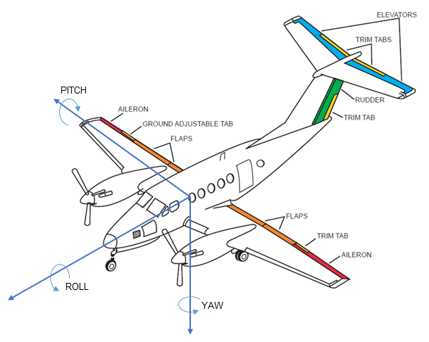
The Cessna 441 is fitted with conventional flight controls connected to the aircraft’s primary flight control surfaces. The primary flight controls consist of the rudder, elevators, and ailerons, which control the aircraft about the yaw, pitch and roll axes respectively.
The pilot controls an aircraft by manipulating the control wheel and rudder pedals, which deflect the ailerons, elevators and rudder. Deflection of an aircraft’s primary flight control surfaces changes the aerodynamic shape and therefore the amount of lift generated by the associated part of each wing, vertical stabiliser or horizontal stabiliser. These local variations in lift result in changes to the aircraft attitude and consequently flight path.
Any deflection of the primary flight control surfaces into the adjacent airflow produces aerodynamic forces on the surface and corresponding loads on the control wheel or rudder pedals. The magnitude of the aerodynamic force is principally related to the amount of flight control surface deflection, airspeed and trim tab deflection.
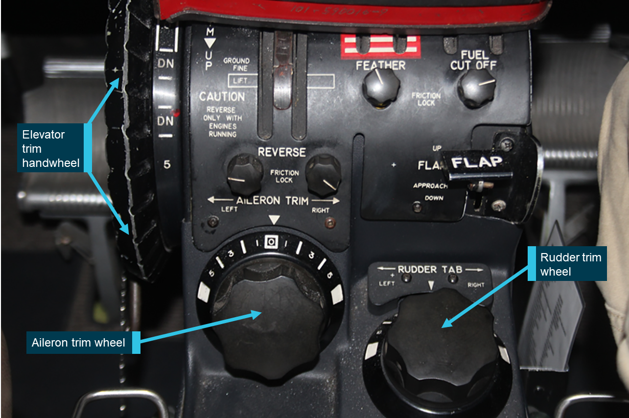
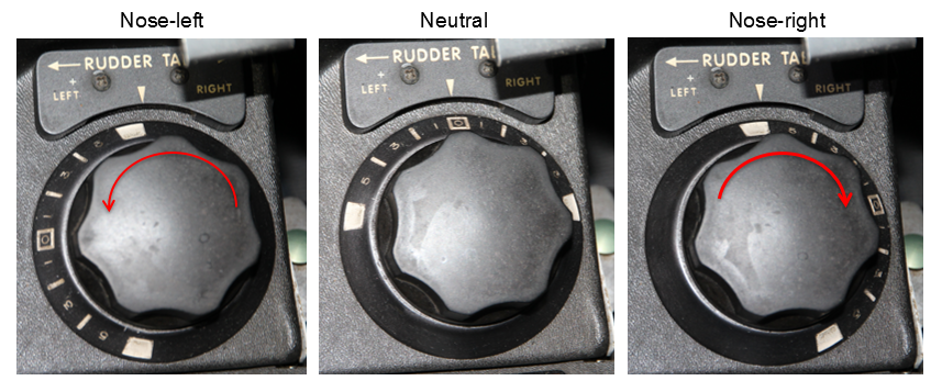
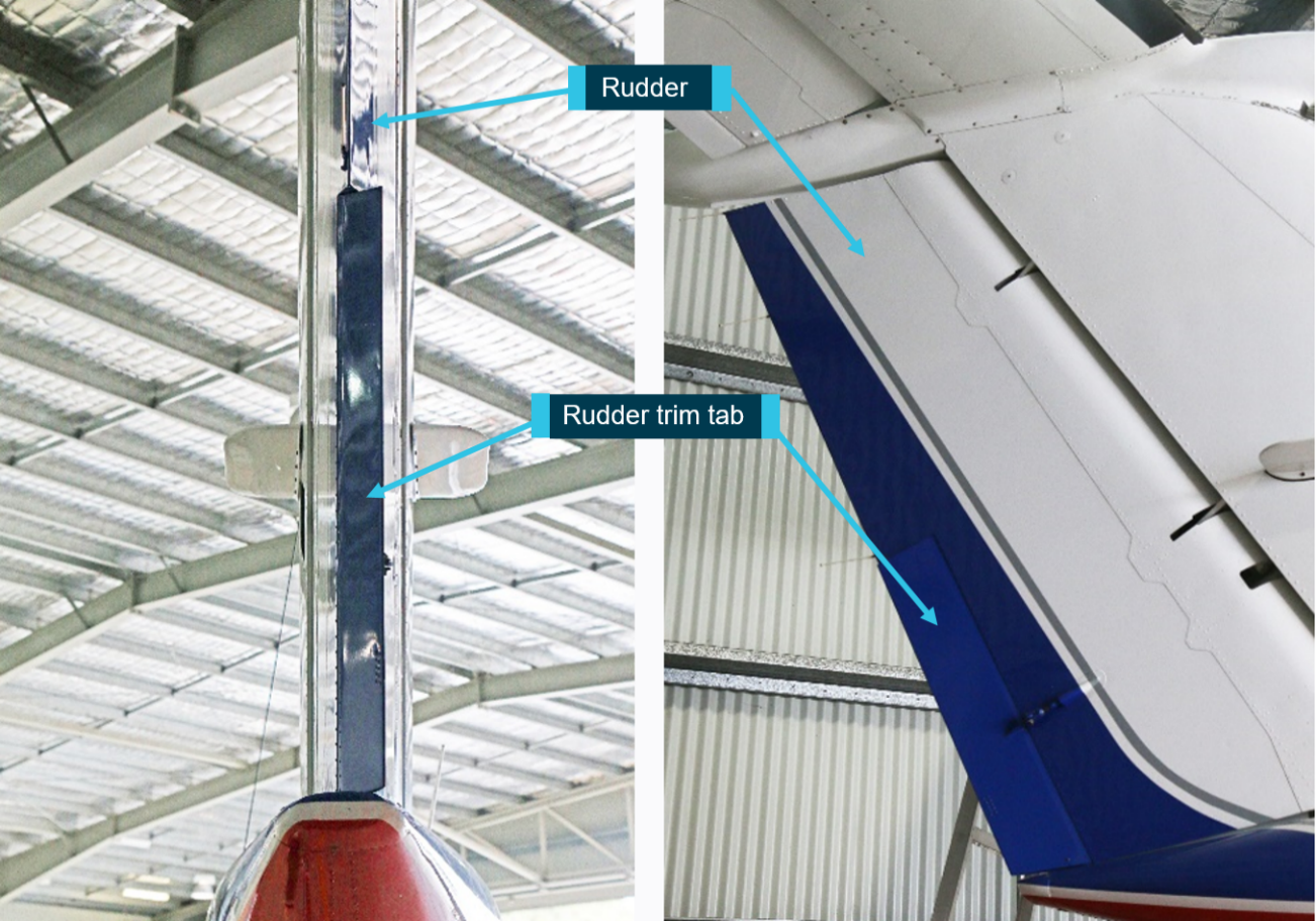
On the Cessna 441, adjustable trim tabs are attached to the trailing edge of the primary flight controls. These tabs are used to ‘trim’ or counteract the aerodynamic forces felt by the pilot on the control wheel or rudder pedals. During flight, deflection of an aircraft’s trim tab produces an aerodynamic force on the aft part of the associated primary surface. The tabs have the capacity, when adjusted in the opposite direction to the deflection of the primary control surface, to modify the aerodynamic force on the surface and correspondingly, reduce the load felt by the pilot on the control wheel or rudder pedals. The effectiveness of a trim tab is principally related to the amount of deflection and the aircraft’s airspeed.
Flap system description
The aircraft has four flaps, one inboard, and one outboard per wing. The flaps are normally in the fully retracted position. They are extended to slow the aircraft and allow it to land at a lower airspeed. They can also be used to improve take-off performance in the ‘T.O.’ position. The flaps are operated using a sliding selector. Flap travel is registered on an indicator adjacent to the selector. There are four detents in the selector assembly as follows:
UP – fully retracted, 0⁰ of travel
T.O. – 10° of flap down travel
APPR – 20⁰ of flap down travel
LAND – full extension, 30⁰ of flap down travel.
Engine and propeller controls
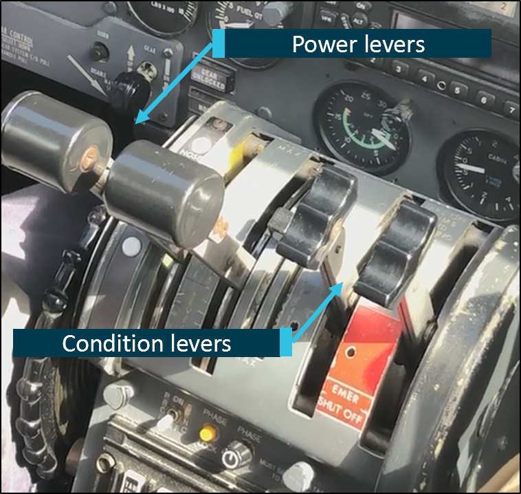
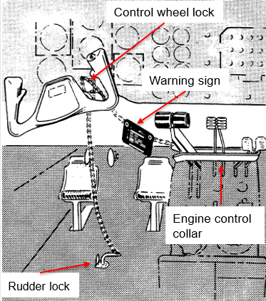
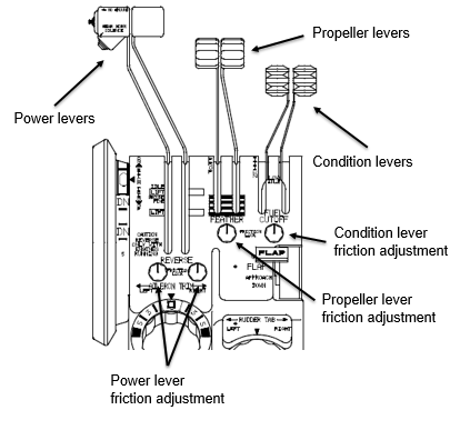
Each engine is controlled by two levers located in the engine controls section of the centre pedestal (Figure 3).
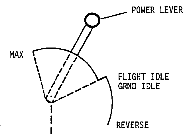
The power levers provide control input to the engine for the power necessary throughout the entire operational envelope. The power lever has the following positions:
MAX
AIR START
FLIGHT IDLE
GROUND IDLE
REVERSE
The power levers can be moved freely forward of FLIGHT IDLE. A hard stop is provided at the FLIGHT IDLE position to prevent inadvertent selection of reverse thrust in flight (Figure 4). Finger latches located on each power lever must be pulled up to allow movement of the power levers rearward of the FLIGHT IDLE position.
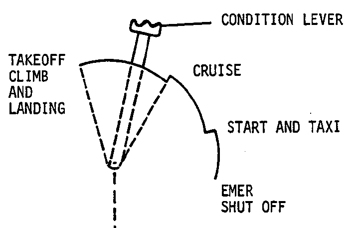
The condition levers are used to set the engine revolutions per minute required for flight as well as acting as the control for propeller feathering and emergency fuel shut-off. The condition lever quadrant has the following positions:
TAKEOFF, CLIMB and LANDING
CRUISE
START AND TAXI
EMER SHUT-OFF
The condition levers can be moved freely forward of CRUISE. A hard stop is provided at the CRUISE position to prevent inadvertent selection of START AND TAXI speed in flight (Figure 5). Each condition lever must be pulled up to allow movement rear of the CRUISE stop. Another stop is provided at the START AND TAXI position. Rearward movement past this position allows the respective engine to be shut down and its propeller feathered.
Figure 3: Engine control levers
Source: ATSB
Figure 4: Power lever
Source: Textron Aviation Inc.
Figure 5: Condition lever
Source: Textron Aviation Inc.
Negative torque system
The aircraft’s engines are equipped with a negative torque sensing (NTS) system that activates under conditions of low propeller pitch (see the section titled Multi‑engine aeroplane propellers) when air loads drive the propeller instead of the engine. This can occur during normal operation at high airspeed and low power settings but will also happen following an engine failure. When NTS activates, the propeller blades are automatically driven towards the feathered[7] position to reduce both the air load and the significant associated drag. NTS will only activate while negative torque is detected so, unlike an auto‑feather system fitted to other aircraft, the blades will only automatically move to a high pitch position rather than fully feathered. Consequently, in the event of an engine failure the pilot is required to move the condition lever to the emergency shut off position to feather the propeller.
With regard to functioning of the NTS, the POH noted that:
NTS operation, as evidenced by a cycling sound of the engine(s) can occur at high airspeed with the power levers at FLIGHT IDLE; this is particularly true when operating in manual mode. NTS operation occurs when the propeller is driving the engine, rather than the engine driving the propeller. During normal mode operation, NTS can indicate the fuel flow is insufficient for existing conditions.
There is a POH requirement to confirm operation of the NTS prior to flight. Normal operation of the NTS on the ground is accompanied by illumination of an amber light on the cockpit annunciator panel for the respective engine being checked. The light was for check purposes only and would not illuminate during in‑flight activation of the NTS. Activation of the NTS on an operative engine in flight can be overcome by advancing the power levers slightly.
Manual mode operation
Manual mode refers to the engine power output being directly controlled by the power lever position rather than by a signal sent to the engine by the electronic engine control unit (EEC). The power system is designed so that fuel scheduling is lower in manual mode than it is in normal (automatic) mode.
Higher power lever positions are therefore required to maintain engine power when in manual mode compared to normal mode. This means that if a fault is detected in the EEC and the engine operation automatically reverts to manual mode the engine will have a reduction in power for that particular power lever setting. If that occurs the power can be restored by advancing the power lever as required.
Weight and balance
The ATSB determined the likely fuel on board at the time of the accident and the weight and location of people, baggage and ballast. From this information, it was calculated that the aircraft was within the weight and balance limitations specified in the aircraft’s POH and relevant supplements. The aircraft’s weight at the time of the accident was estimated to be about 3,950 kg. The aircraft’s maximum take-off weight was 4,690 kg.[8]
Meteorological information
The forecast weather conditions at Renmark Airport on the afternoon of the accident were benign with a southerly wind at 14 kt, visibility in excess of 10 km and scattered[9] cloud at 4,000 ft above the airport.
Weather observations recorded at one‑minute intervals by an automatic weather station at the airport were obtained from the Bureau of Meteorology (BoM). Consistent with the forecast, in the 20 minutes preceding the accident the wind strength varied between 8‑13 knots, and the direction varied between 188‑205° magnetic. The cloud cover was consistently seven oktas at about 6,500 ft above the airport and the ambient temperature was 13°C.
The ATSB also sought the assistance of the BoM to assess the likely wind strength and direction at the operating altitude of the aircraft immediately prior to the loss of control. This was done to enable an assessment of the airspeed during the final flight segment using recorded groundspeed data (see the section titled Recorded flight data).
Airport information
Renmark Airport is at an elevation of 115 ft above mean sea level and has one sealed runway, 07/25, and one gravel runway, 18/36.3 As there is no air traffic control tower at the airport, traffic at the airport broadcast on a common traffic advisory frequency to advise intentions and arrange separation with other traffic.
The terrain west of the airport, along the extended runway centreline in XMJ’s departure direction, slopes upwards, with an elevation gain of about 60 ft between the runway and the accident site location.
Circuit operations
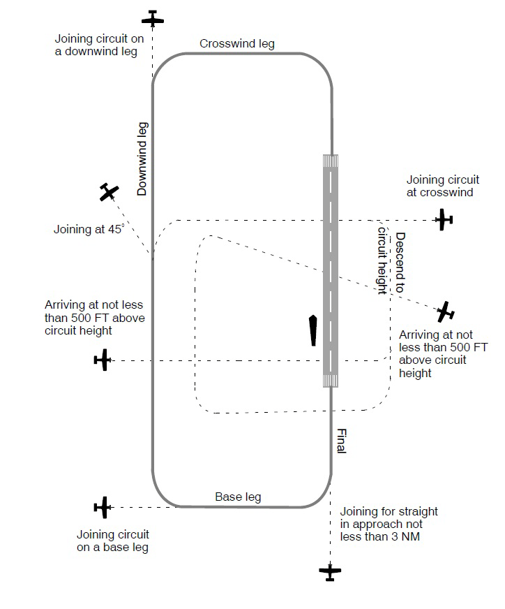
In order to assure a safe and orderly traffic flow into and out of an airport, a standard circuit traffic pattern is used. The circuit consists of four legs: crosswind, downwind, base and final as shown in Figure 6, with standardised methods for joining the pattern to avoid traffic conflicts.
Figure 6: Standard circuit pattern
Source: Airservices Australia
Asymmetric flight
Multi-engine aeroplanes
In a discussion of small[10] multi-engine aeroplane operations, the United States Federal Aviation Administration (FAA) Airplane Flying Handbook FAA‑H‑8083‑3B, stated:[11]
The basic difference between operating a multiengine airplane and a single-engine airplane is the potential problem involving an engine failure. The penalties for loss of an engine are twofold: performance and control. The most obvious problem is the loss of 50 percent of power, which reduces climb performance 80 to 90 percent, sometimes even more. The other is the control problem caused by the remaining thrust, which is now asymmetrical. Attention to both these factors is crucial to safe OEI [one engine inoperative] flight. The performance and systems redundancy of a multiengine airplane is a safety advantage only to a trained and proficient pilot.
The importance of maintaining one engine inoperative performance and control was further emphasised in the handbook as follows:
In OEI flight at low altitudes and airspeeds such as the initial climb after takeoff, pilots must operate the airplane so as to guard against the three major accident factors: (1) loss of directional control, (2) loss of performance, and (3) loss of flying speed. All have equal potential to be lethal. Loss of flying speed is not a factor, however, when the airplane is operated with due regard for directional control and performance.
Multi-engine aeroplane propellers
In the event of an engine power loss, the inoperative engine may windmill - continue to rotate due to the airflow acting on the propeller. The FAA handbook described the hazard of a windmilling propeller as follows:
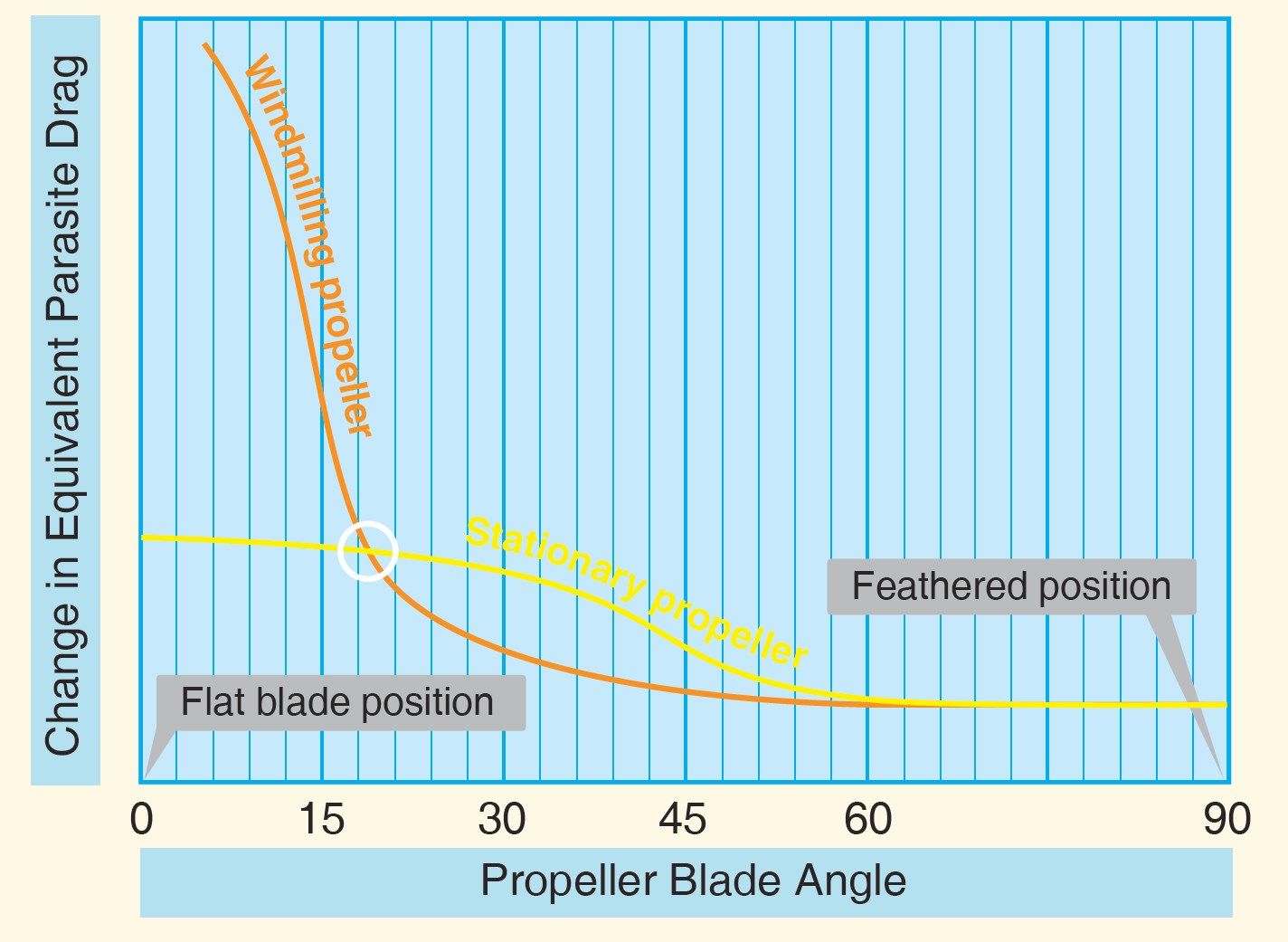
The propeller windmilling at high speed in the low range of blade angles can produce an increase in parasite drag, which may be as great as the parasite drag of the basic airplane.
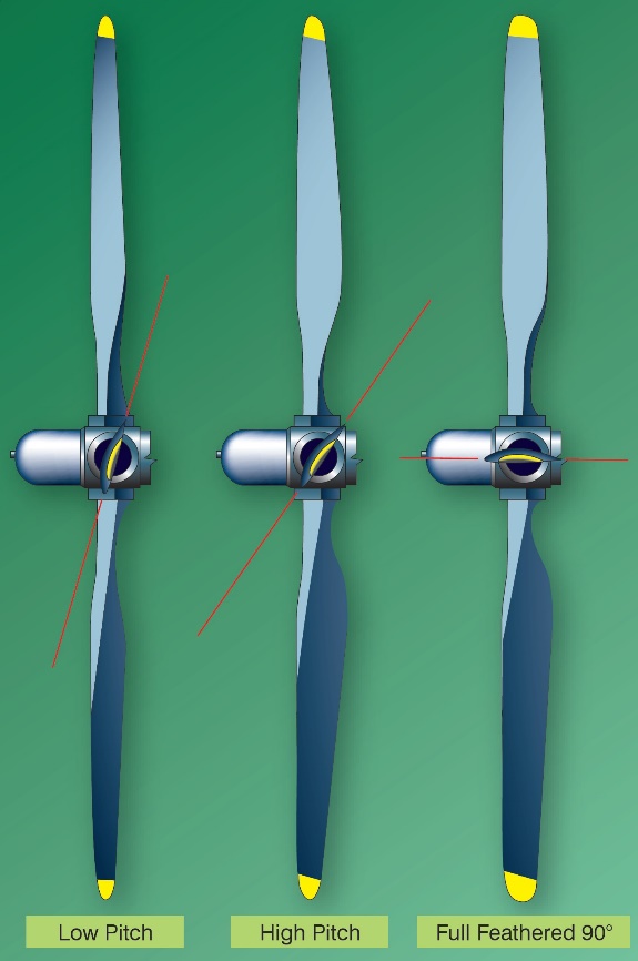
In order to minimise this significant source of drag on single engine controllability and climb performance, the propellers of multi-engine aeroplanes are capable of aligning the blades with the airflow (Figure 7).
Figure 7: Multiengine aeroplane propeller
Source: United States Federal Aviation Administration
This ‘feathered’ configuration stops the rotation of the engine and propeller and significantly reduces the parasite drag compared to that associated with a windmilling propeller (Figure 8).
Figure 8: Propeller drag
Source: United States Federal Aviation Administration
Asymmetric control
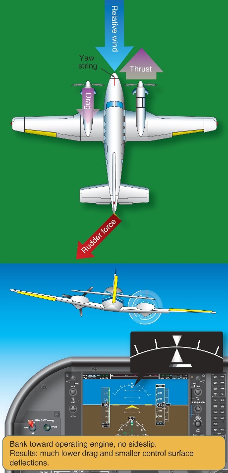
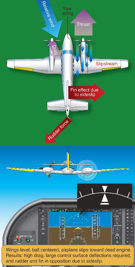
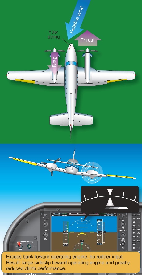
The majority of small, multi-engine aeroplanes like the Cessna 441 have two wing‑mounted engines that produce symmetrical propeller thrust during normal operation. One engine inoperative (OEI) flight in these aeroplanes results in asymmetric thrust and drag due to the offset position of the engines from the aeroplane’s centreline. The result is a tendency for the nose of the aeroplane to turn in the direction of the inoperative engine. The extent of the yaw may vary depending on which engine becomes inoperative, with the inoperative engine that produces the greatest degree of asymmetry being termed the ‘critical’ engine.[12]
The asymmetric yawing tendency may be countered through the application of rudder and aileron control inputs. As the effectiveness of an aircraft’s control surfaces generally decreases with decreasing airspeed, sufficient airspeed must be maintained while operating OEI to ensure that the rudder and aileron retain sufficient control authority to maintain directional control of the aeroplane.
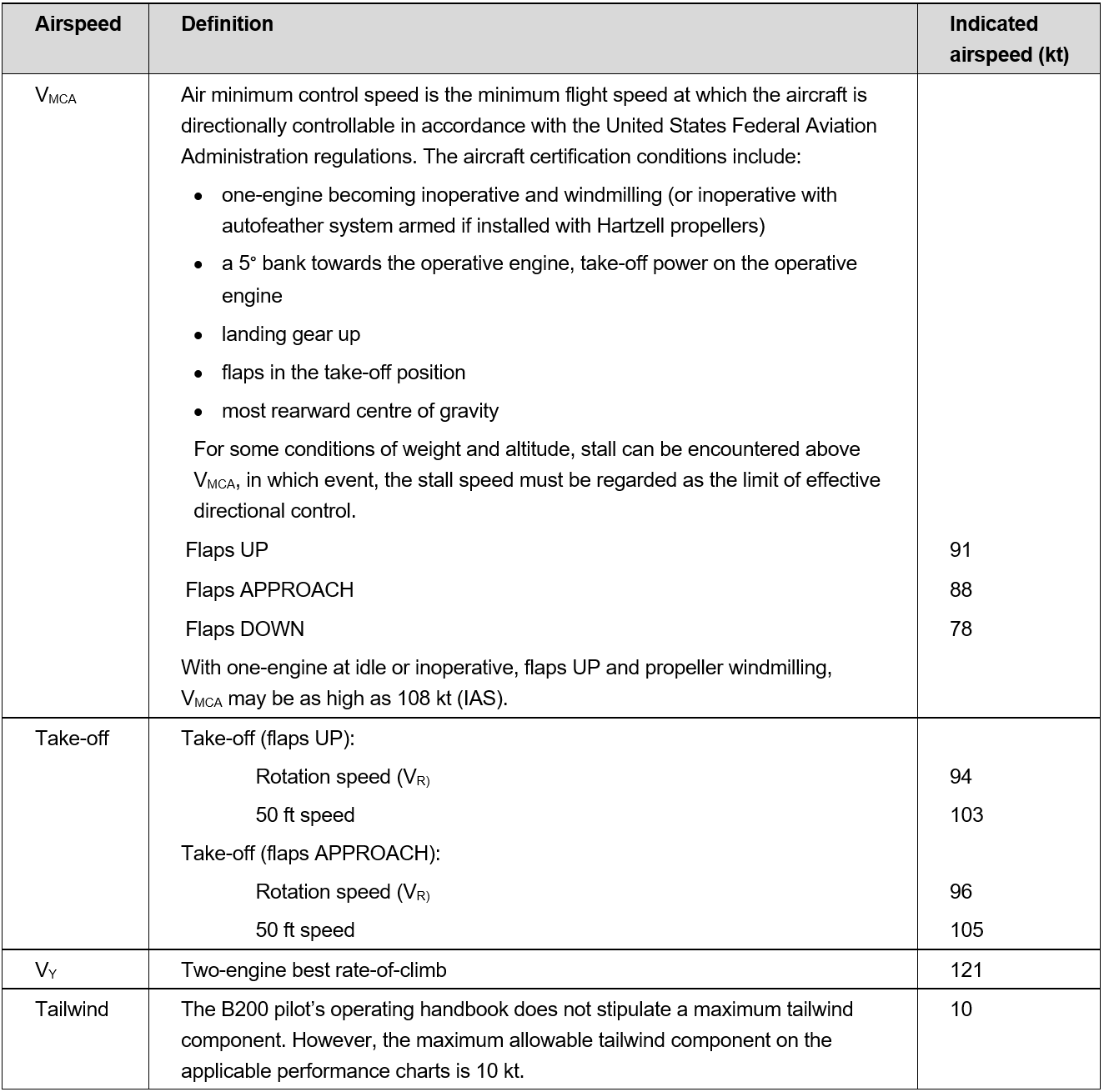
The minimum control airspeed with the critical engine inoperative (VMCA) is established by test pilots during aircraft certification under a specific set of conditions, and is marked on the air speed indicators of most multi-engine aeroplanes with a red radial line. VMCA is influenced by a large number of factors, including an aircraft’s configuration/loading, operating altitude and pilot control inputs and is therefore likely to vary from the stated value.
The VMCA published in the Cessna 441 pilots operating handbook (POH) was 91 kt indicated airspeed. The POH further stated that:
The airplane must reach the air minimum control speed (VMCA) before full control deflections are able to counteract the roll and yaw tendencies associated with one engine inoperative and full power operation on the other engine. VMCA with wing flaps in take-off position is indicated by a red radial on the airspeed indicator. VMCA with wing flaps in the UP position and the airplane in an en-route climb configuration will be buffet limited and occur at a higher speed.
In addition to the published VMCA the POH also listed an ‘intentional one engine inoperative’ indicated airspeed of 98 kt with advice that:
Although the airplane is controllable at the air minimum control speed, the airplane performance is less than optimum. A more suitable speed with wing flaps positioned in take-off is 98 KIAS [kt indicated airspeed]. This speed is identical to the normal rotation speed, thus the pilot can direct more of this attention to determining and securing the inoperative engine than to achieving a speed not normally associated with take-off. This speed also provides additional safety for controllability and allows easier maintenance of altitude during the period of gear retraction and securing the inoperative engine.
As detailed in the FAA handbook, maintaining directional control following an engine failure during take‑off and initial climb is especially critical:
The first consideration following engine failure during takeoff is to maintain control of the airplane. Maintaining directional control with prompt and often aggressive rudder application and STOPPING THE YAW is critical to the safety of flight. Ensure that airspeed stays above VMC [VMCA]. If the yaw cannot be controlled with full rudder applied, reducing thrust on the operative engine is the only alternative. Attempting to correct the roll with aileron without first applying rudder increases drag and adverse yaw and further degrades directional control.
Asymmetric performance
Optimum single-engine climb performance is obtained by flying the aircraft at the published OEI best rate of climb speed (VYSE), 120 KIAS for the Cessna 441, with maximum available power and minimised drag. Minimum drag is achieved by:
retracting the flaps and landing gear
feathering the propeller of the inoperative engine
minimising sideslip by presenting the smallest aircraft profile to the relative wind.
During symmetrical flight in a single-engine airplane, or a multiengine airplane with both engines operating, zero sideslip occurs when the balance ball[13] is centred. However, in the case of asymmetric thrust, zero sideslip requires a combination of bank angle and non‑centred ball position. That is, a combination of rudder and aileron inputs (Figure 9).
As it related to the Cessna 441, the POH provided the following information on the required combination of rudder and aileron inputs to minimise sideslip:
Best single-engine climb is attained with the wings banked approximately 3° to 4° and with a ⅔ to ¾ ball slip into the operative engine when the airplane is at low airspeed and heavy weight. As airspeed increases and/or airplane weight is significantly reduced, the ⅔ to ¾ ball slip becomes less important.
Figure 9: Zero sideslip
Source: United States Federal Aviation Administration
While it is possible to counteract asymmetric thrust using only rudder or only aileron, this results in significant performance and controllability penalties. Specifically, countering asymmetry with level wings and the ball centred (large rudder input towards the operative engine) results in moderate sideslip towards the inoperative engine that reduces climb performance (Figure 10). It also significantly increase VMCA as there is no horizontal component of lift to assist the rudder to counter the asymmetric thrust. In discussing this increase in minimum control speed as it related to the Cessna 441, the Civil Aviation Advisory Publication (CAAP) 5.23‑1(2) Multi-engine aeroplane operations and training stated:
…Flight tests in an instrumented Cessna Conquest showed that with a published VMCA [VMCA] of 91 kts, if the aircraft was flown in asymmetric flight with full power applied and the wings held level with the rudder balancing the aircraft, minimum control speed increased to 115 kts, an increase of 24 kts.
Figure 10: Rudder‑only input
Source: United States Federal Aviation Administration
Opposing asymmetric thrust using only aileron input results in a large sideslip towards the operative engine that also significantly reduces climb performance (Figure 11).
Figure 11: Aileron‑only input
Source: United States Federal Aviation Administration
OEI rate of climb performance for given operating conditions can be determined using data published in the POH/flight manual. Achieving the published performance relies on use of the zero sideslip technique and configuring the aircraft for minimum drag.
Considering the configuration and approximate weight of the aircraft at the time of the accident (see the section titled Weight and balance), the calculated OEI climb rate over a range of indicated airspeeds is shown in Table 1.
Table 1: One engine inoperative climb performance for Cessna 441 at 3,950 kg
Indicated airspeed (kt)
Excess Thrust Horse Power (HP)
Calculated climb rate (ft/min)
90
115.7
438
100
185.1
701
110
205.4
778
120
213.4
809
130
211.7
802
Source: ATSB analysis from aircraft certification data
The OEI performance data indicated that XMJ was capable of achieving a positive rate of climb following departure from Renmark if sideslip and other sources of drag were minimised.
Engine failure simulation
Zero thrust
Demonstration of OEI flight often involves simulating a failed engine by moving the power lever to a low power level rather than actually shutting down the engine and feathering the propeller. This method of simulation allows rapid normal power restoration. However, as detailed in the section titled Multi-engine aeroplane propellers, at low power settings the propeller will rotate due to the airflow rather than the engine, creating much higher drag than a feathered propeller. For that reason, a zero thrust power level is commonly set to overcome the drag associated with windmilling and more accurately simulate the low drag associated with a feathered propeller.
Zero thrust varies depending on the engine type, airspeed, altitude and temperature. In a piston engine aircraft zero thrust is normally achieved by setting a manifold pressure that results in a specific propeller rpm. In a turbine propeller engine zero thrust is expressed as an engine torque, and in some cases rpm, for a particular airspeed (normally VYSE).
Aircraft manufacturer’s procedures
The Cessna 441 POH detailed two procedures for simulating an engine failure, however neither procedure involved the use of a zero thrust power setting.
The first POH procedure was designed to practice management of an engine failure during the cruise phase of flight. The procedure involved retarding the power lever to the AIRSTART position and then shutting the engine down. In discussing the AIRSTART power lever position, the POH stated:
The AIRSTART position does provide some forward thrust. This position is recommended as it allows the best exhaust gas temperature stabilization before shutdown and it is the lowest position which will prevent the fuel computer from tripping to manual mode during an airstart.
If the power lever is retarded below the AIRSTART position and the fuel computer trips to manual mode, normal mode may be regained by advancing the power lever slightly and cycling the fuel computer switch to OFF then back to ON.
The second procedure was designed to train pilots to handle an engine failure in the take-off configuration. This involved using a fuel interruption process to actually shut the engine down. This was achieved by momentary selection of the engine stop button which activated a solenoid within the fuel control unit and cut off the fuel supply to the engine. In order to also simulate representative control forces during the exercise, the set up for the sequence involved:
extending the landing gear
extending the wing flaps to the take‑off position
trimming the aircraft for a speed greater than the intentional one engine inoperative speed of 98 kt.
This procedure directly referenced related guidance in the POH, applicable to the demonstration of VMCA, which stated:
One engine inoperative procedures should be practiced in anticipation of an emergency. This practice should be conducted at a safe altitude (5000 ft AGL), with full power on both engines, and should be started at a safe speed of at least 98 KIAS. As recovery ability is gained with practice, the starting speed may be lowered in small increments until the feel of the airplane in emergency conductions is well known. It should be noted that as the speed is reduced, directional control becomes more difficult. Emphasis should be placed on stopping the initial large yaw angles by the IMMEDIATE application of rudder supplements by banking slightly away from the yaw. Practice should be continued until: (1) an instinctive corrective reaction is developed and the corrective procedure is automatic, and (2) airspeed, altitude and heading can be maintained easily while the airplane is being prepared for a climb.
The POH did not contain any procedure relating to simulation of an engine failure during the actual take‑off phase.
Additionally, for Cessna 441 aircraft with the serial number 0173 onwards (not applicable to VH‑XMJ) the POH, in reference to the ‘engine shutdown to simulate engine failure in takeoff configuration’ procedure (second procedure), explicitly stated
“This procedure must not be practiced at an altitude below 5,000 ft AGL”
Some of Rossair’s other Cessna 441 aircraft operated under this later POH, but the operators manual did not note a difference between the two handbooks.
With respect to the change in the POH procedures applicable to serial number 0173 and onwards, the aircraft manufacturer advised that:
there was no material difference between the aircraft from serial numbers 0173 and onwards and the earlier serial numbers (0172 and prior) that necessitated a different method of simulating an engine failure in the take-off configuration
the statements in the earlier POH procedure that referenced the demonstration of VMCA have the same intent as the warning note in the POH for aircraft with serial numbers 0173 and onwards, which states this procedure must not be practiced at an altitude below 5,000 feet above ground level.
Operator’s procedures
Rossair’s operations manual contained information relating to simulated engine failures in both Part A (general operations) and Part C (training and checking). Part A of the manual stated:
Simulated asymmetric flight is not to be carried out unless specifically authorised, and then only when accompanied by an authorised person. Asymmetric flight shall not be carried out when passengers are being carried and shall only be conducted on a designated training flight.
Any engine failure simulation shall be conducted by closing the power lever to a position equivalent to zero thrust (Turbine) in accordance with Part C, or moving the mixture lever to the idle cut off position (Piston).
For the purpose of training, simulated engine failures and the feathering of aircraft propellers shall only be conducted in VMC conditions. In addition, the aircraft shall be operating above 3000 ft AGL, unless the simulation or feather practice is specifically required during the approach and landing phase.
Following any practice engine shut-down in flight, the engine controls must be set for an immediate restart.
At no time are stalling or Vmca demonstrations to be made with the aircraft propeller feathered.
Part C contained detailed information on the procedure for simulating engine failures in the Cessna 441 (Figure 12). However, the procedure varied from that outlined in Part A with regard to initial power settings and the height at which the simulation could be initiated.
Part A detailed that engine failure simulation for training purposes was to occur above 3,000 ft above ground level unless specifically required during the approach and landing phase. Part C permitted the simulation of engine failure ‘After attaining the higher of 400’ or acceleration altitude’. The reference to ‘acceleration altitude’ was not applicable to the Cessna 441.
Figure 12: Rossair training and checking manual
Source: AE Charter/Rossair
The Part C procedure involved retarding power to flight idle (power level to minimum) and then advancing the power to zero thrust (to represent a feathered propeller) on completion of the engine failure drills. This is the normal technique used for simulating the failure of a piston engine aircraft, where the pilot must manually feather the propeller.
It is not necessary to select less than a zero thrust setting to simulate failure of a turboprop engine equipped with auto feather or negative torque sensing systems (such as the Cessna 441). More importantly, setting the power lever below the zero thrust setting will increase propeller drag. As detailed previously, selection of less than the AIRSTART power lever position in the Cessna 441 can also affect automatic operation of the fuel computer.
An earlier version of the company operations manual detailed simulation of a failed engine on a turboprop engine by only moving the power lever to zero thrust. The ATSB could not determine how the procedure involving moving the power to below zero thrust was introduced into the 2016 version of the manual (in use at the time of the accident). However it may have occurred during the merger of Rossair with another company (see section titled Overview of the operator). Additionally, this section of the operations manual was approved by the Civil Aviation Safety Authority without detection of the error (see section titled Regulatory services processes).
Finally, the propeller manufacturer advised that for the four‑bladed propellers fitted to XMJ, the required zero thrust setting was about 234 ft.lbs of engine torque, 116 ft.lbs less than stated in Part C of the operations manual.
Regulatory guidance
CAAP 5.23‑1(2) Multi-engine aeroplane operations and training, provided comprehensive guidance on the operation of multiengine aeroplanes. With regard to the simulation of engine failures, it stated:
Before simulating engine failures in multi-engine aircraft, instructors must be aware of the implications and be sure of their actions. Consult the aircraft flight manual or POH for the manufacturer’s recommended method of simulating an engine failure.
The CAAP also provided guidance on setting power to simulate a failed engine. Specifically, it was recommended to initially close the throttle of a piston engine to replicate a windmilling propeller and then set zero thrust once the trainee had simulated propeller feathering. In the case of a turboprop engine, replication of an engine failure only required selection of zero thrust. Guidance was also provided on a method to establish zero thrust if it was not specified.
The CAAP also detailed a number of risks associated with multi-engine training, including:
inappropriate management of complex aircraft systems
conducting flight operations at low level (engine failures after take-off)
conducting operations at or near VMCA or VSO [stall speed with undercarriage and flap selected] with an engine inoperative
asymmetric operations.
With regard to flight operations at low level, the CAAP further stated:
Any flight operation at low altitude has potential dangers. Trainers have debated over the decades on the value of practicing engine failures after an actual take-off, near the ground. The general consensus is that despite the risks, pilots must be trained to manage these situations in multi-engine aircraft.
…Instructors should consider not simulating engine failures below 400 ft above ground level (AGL) to provide a reasonable safety margin.
Accident flight procedure
There was insufficient information and recording devices to determine the specific procedure used to simulate the engine failure after take‑off from Renmark Airport. However, the electronic briefing developed by the chief pilot in preparation for the occurrence check flight provided specific guidance on how engine failures were to be simulated as follows:
All failures will be preceded by the phrase “simulated”
• Once the memory items have been carried out, zero thrust will be set
• The instructor will handle the ‘failed’ engine
• Pilot is to use other power lever as required
• When landing, pilot may retard both levers as required
Any failure not preceded with the phrase “simulated” is real and shall be treated as such.
In preparation for the occurrence check flight, a practice flight covering similar sequences was conducted in XMJ the week before with the chief pilot and inductee pilot. That flight also had an observer on board with extensive Cessna 441 check pilot experience. The practice flight was not conducted as a training flight, but rather a private flight with two licenced and experienced pilots on board, preparing for their respective roles during the CASA check flight.
The observer advised that during the practice flight, the engine failure was simulated by the chief pilot reducing the power lever but not all the way to the flight idle stop. He further recalled that once the inductee pilot completed the initial response actions, the chief pilot partially advanced the power lever. The observer stated that, based on his experience, zero thrust in the occurrence aircraft was about 150 ft.lbs of torque and lower than other company Cessna 441 aircraft. He also recalled that the chief pilot set a power lever position at or slightly above that torque value during the simulation.
Stall speed
The calculated stall speed depends on the weight of the aircraft, as well as the gear and flap configurations, and the angle of bank. For XMJ, at the ATSB calculated take-off weight from Renmark Airport (3,950 kg), with:
gear and flap retracted
power at the flight idle,
the calculated stall speed with wings level was 85 KIAS. At 20° angle of bank, the stall speed increased to approximately 88 KIAS.
Flight recorders
XMJ was not equipped with a flight data recorder or cockpit voice recorder. Requirements relating to the fitment of flight recorders is detailed in Civil Aviation Order (CAO) 20.18 as follows:
An aircraft of maximum take-off weight:
a) In excess of 5,700 kg and which is:
i. turbine powered; or
ii. of a type first certificated in its country of manufacture on or after 1 July 1965;
shall not be flown (except in agricultural operations) unless it is equipped with an approved flight data recorder and an approved cockpit voice recorder system;
b) Less than or equal to 5,700 kg and which is:
i. pressurised; and
ii. turbine powered by more than one engine; and
iii . of a type certificated in its country of manufacture for operation with more than eleven places; and
iv. issued with its initial Australian Certificate of airworthiness after 1 January 1988;
shall not be flown unless it is equipped with an approved cockpit voice recorder system.
The Cessna 441 has a maximum take‑off weight of 4,468 kg so CAO 20.18(a) was not applicable. Additionally, although meeting a number of the criteria detailed in CAO 20.18(b), the Cessna 441 is certified for a maximum of eleven seats (two crew and nine passengers). The aircraft was therefore not required to be fitted with either a flight data recorder or a cockpit voice recorder.
Recorded flight data
As part of the investigation, data broadcast by the automatic dependent surveillance broadcast (ADS-B) equipment fitted to the aircraft was obtained from various web-based providers. Depending on the provider, this data recorded the following parameters at intervals of either 6 or 15 seconds:
latitude and longitude
time of the logged position
pressure altitude
groundspeed
track.
A review of the data identified that the aircraft descended outside ADS-B coverage as it approached the circuit area at Renmark Airport. Consequently, no ADS-B flight data was available for the departure of XMJ from Renmark.
However, GPS data transmitted from an on board mobile device with the OzRunways application installed was able to be sourced. This data was available at 5 second intervals with the GPS altitude truncated to the nearest 100 ft and accurate to about -30/+130 ft of the recorded value. The OzRunways data parameters were compared with ADS‑B information from earlier stages of the flight and was found to be consistent. That provided assurance that the OzRunways data was valid and could be relied upon for analysis of the final flight segment. Although the recorded parameters were considered representative of the actual flight profile, it was not possible to determine how they varied between sample points.
Using the GPS groundspeed, and wind information obtained from the BoM, the aircraft’s true airspeed (TAS) was calculated. The TAS values were then converted to a calculated indicated airspeed (IAS) using altitude and temperature data. Given the relatively low operating altitude, the IAS varied only slightly from the calculated TAS. The airspeed and height above the ground variation over the final 1 minute of the flight, referenced to the elapsed time from take‑off, is shown in Figure 13.
Figure 13: Indicated airspeed and altitude variation over the final minute of flight
Source: ATSB
The data showed a steady increase in airspeed up to about 132 kt, followed by loss of airspeed, brief stabilisation around 110‑115 kt, then a further decrease to about 107 kt before the data ended. The maximum recorded airspeed was about 10 kt higher than published OEI best rate of climb speed VYSE (120 kt, see the section titled Asymmetric performance) and occurred at a height of about 300 ft above ground level.
That height was derived from the recorded GPS altitude of 400 ft less 100 ft for the approximate runway elevation (see the section titled Airport information). Noting that the GPS altitude was truncated to the nearest 100 ft and had an accuracy of about ‑30/+130 ft, a height of 300 ft above the ground was indicative of an actual height range between 270‑420 ft above the ground.
Analysis of the indicated airspeed and height profiles indicated that, on attaining the minimum operator‑specified conditions for initiation of a simulated engine failure, the variation in airspeed and altitude was consistent with a reduction in performance associated with OEI flight.
The airspeed subsequently decreased below the target airspeed of VYSE and remained below that airspeed for the final 35 seconds of the data. The final airspeed value of 107 kt was above both the calculated stall speed (see the section titled Stall speed) and the published minimum control airspeed VMCA. However, it was below the VMCA range established during flight testing in the Cessna 441 (see the section titled Asymmetric performance).
Figure 14 illustrates the difference in the calculated IAS and height (above ground level) profiles between the departure from Renmark Airport and the earlier departure from Adelaide Airport.
Figure 14: Departure profile comparison
Source: ATSB
In addition to the airspeed variation, the aircraft’s rate of climb was derived from the GPS altitude data and is shown, together with the aircraft’s track deviation from the runway heading in Figure 15. The data indicated that the aircraft initially climbed at greater than the expected OEI rate of climb before levelling and maintaining approximately level flight for 30 seconds until the data ended. A review of the airspeed over the same time period identified that it reduced during the peak increase in the rate of climb, suggesting that the aircraft was pitched up to reduce airspeed.
Analysis of the track variation identified that the aircraft deviated to the right of the runway centreline during the final minute of the flight. That movement was consistent with both the prevailing left crosswind component during the departure and a reduction in power on the right engine.
Figure 15: Rate of climb and track variation over the final minute of flight
Source: ATSB
Operational information
Pilot licencing
Each of the three pilots on board held a Civil Aviation Safety Regulations 1998 (CASR) Part 61 licence. CASR Subpart 61E requires that pilots meet a series of ongoing requirements in order to exercise the privileges of their licence. Relevant requirements are discussed below.
Pilot recency requirements for carriage of passengers
CASR Part 61.395 outlines the recent experience requirements that pilots must have in order to carry passengers. By day, this includes at least three take-offs and three landings within 90 days in the aircraft. A pass in a flight check meets this requirement.
The Rossair operations manual (Part A) reflected the Part 61 requirements for landings and included the company recency requirements for conducting instrument approaches.
Both of the pilots in the control seats met the recency requirements for the flight they were conducting.
Class and type rated aircraft
Under the regulations prior to CASR Part 61, particular aircraft required a pilot to be trained, endorsed and checked on that aircraft type in order to operate that specific type. Under Part 61, there are still some aircraft which come under this requirement (‘type rated aircraft’), such as the Embraer EMB 120, but other aircraft are included in a class rating (‘class rated aircraft’). This means that a check on any aircraft in the class rating covers all other aircraft in that class rating. Pilots must complete a flight review for the class rating every two years to continue operating aircraft in that class.
The Cessna 441 is in the multi-engine class rating. However, the complexity of the aircraft is recognised by CASA, who requires that pilots that wish to operate the Cessna 441 first complete flight training and a flight review in this aircraft type, before it becomes covered by the class rating in subsequent years. Other complex twin aircraft covered by this legislation include the Beechcraft King Air C90, King Air B200 and the de Havilland DHC-6 Twin Otter.
As discussed previously (see the section titled Pilot licencing), the CASA FOI renewed his class rating in a Rossair Cessna 441 with the Cessna 441 fleet manager in late 2016. The inductee pilot completed his multi-engine class rating renewal along with his instrument proficiency check in a Beechcraft Baron 95-B55 in February 2017.
The chief pilot had not been checked on a class rated aircraft, since his check pilot training was completed in the Cessna 441 (see the section titled Pilot licencing). In October 2016 he completed his instrument proficiency check (IPC) and type rating renewal in the EMB 120 simulator, which, at that time, under CASA exemption 97/16 satisfied the requirements for the multi-engine class rating renewal. Despite the EMB 120 being a two crew aircraft, and the Cessna 441 being a single pilot operation, the chief pilot was not required to demonstrate on‑going competency in the Cessna 441, as long as he continued to be checked in the EMB 120.
General competency
CASR Part 61.385 ‘Limitations on exercise of privileges of pilots licences – general competency requirement’ states:
1) The holder of a pilot licence is authorised to exercise the privileges of the licence in an aircraft only if the holder is competent in operating the aircraft to the standards mentioned in the Part 61 Manual of standards for the class or type to which the aircraft belongs, including in all of the following areas:
• Operating the aircraft’s navigation and operating systems;
• Conducting all normal, abnormal and emergency flight procedures for the aircraft;
• Applying operating limitations;
• Weight and balance requirements;
• Applying aircraft performance data, including take-off and landing performance data, for the aircraft.
(1A) Subregulation (1B) applies if the holder of a pilot licence also hold an operational rating or endorsement
(1B) The holder is authorised to exercise the privileges of his or her pilot licence in an activity in an aircraft under the rating or endorsement only if the holder is competent in operating the aircraft in the activity to the standards mentioned in the Part 61 Manual of standards (if any) for:
a) The class or type to which the aircraft belongs; and
b) The activity.
In assessing personal competency under this regulation, CASA recommended that ‘pilots should seek advice and consider refresher training or practice before commencing an operation they haven’t carried out for a while’. Although the pilot is already licenced and current on the class of aircraft, training for general competency can only be given by a pilot who holds an instructor rating and appropriate training endorsements.
The check flight briefing (see the section titled Check flight sequences) prepared for the flight had a series of questions at the end of the briefing for the inductee pilot to answer, consistent with the areas of competency identified above. Additionally, the practice flight conducted by the two pilots the week prior was an opportunity to practice the handling skills in this aircraft rather than other aircraft flown by each of the pilots.
Operational proficiency check
A proficiency check is ‘an assessment of your skills and knowledge in a particular operational area. Pilots are required to undertake proficiency checks to ensure they continue to be competent conducting particular kinds of operations’ (CASA Proficiency checks information sheet, 2018). CASA recognises that skill decay occurs over time, and that these checks are an on-going measure to ensure that the licence competencies specified in the CASR Part 61 Manual of Standards continue to be met (see the section titled Skill decay).
Operational proficiency checks are carried out by an operator and may also include the elements required for an instrument proficiency check (IPC), provided the check pilot is authorised to conduct both types of check. The chief pilot in this case was being checked only for approval to conduct OPCs. Operational proficiency checks can only be conducted on pilots employed by that company.
Operating under Civil Aviation Regulations 1988 (CAR) Regulation 217 (see the section titled Organisational structure) Rossair pilots had to pass two proficiency checks per year (listed in the operations manual as alternating between an IPC and OPC), with at least four months between checks, in order to exercise the associated privilege. As the inductee pilot was re-joining the operator, this was his first OPC in the Cessna 441 in over three years. The chief pilot had completed an:
OPC in the Cessna 441 in April 2016 in the left seat, and in May 2016 from the right seat, as part of his Cessna 441 check pilot training
IPC in the EMB 120 in October 2016, and an OPC in the EMB 120 simulator in February 2017.
This met the regulatory and operator requirements for proficiency checking, but did not permit assessment of the chief pilot’s on-going competency in the particular area of single pilot operations.
Practice engine failure after take‑off check requirements
The chief pilot was the pilot primarily being checked during the flight and he had to conduct the inductee pilot’s operational proficiency check in line with the company procedure to be approved as a check pilot.
When a proficiency check is conducted under a CAR 217 approval, the exercises conducted are set by the CAR 217 holder rather than CASA. The Rossair operations manual Part C stated that proficiency checks were to be conducted in accordance with their own check assessment form and the CASA instrument proficiency check form. The company guidance was for check pilots to reference the section of the CASR Part 61 manual of standards for the instrument rating flight test.
When an operator proficiency check is conducted without an instrument proficiency check, there is no CASA requirement for the candidate to demonstrate management of a simulated engine failure after take-off. The Rossair check assessment form however, had a required flight component to ’deal with a simulated engine emergency after take-off requiring an immediate re-landing’.
There are a number of CASA checks which require demonstration of an engine failure after take‑off in a multi-engine aircraft, both for initial issue of a licence or endorsement and during specific types of proficiency checks. The wording of the specified activity varies slightly between checks, for example ’conduct instrument departure (one engine inoperative)’ for the multi-engine class rating; or ’manage an engine failure after take-off (simulated)’ in the multi-engine class rating.
While the wording varied, the competencies are all similar in intent: requiring the pilot to manage the simulated failure while maintaining the aircraft within specified tolerances; and configuring and flying the aircraft to achieve the best performance.
While the manual of standards does not specify a height at which these activities should be conducted, CAAP guidance stated that they should not be conducted below 400 ft above ground level. The requirement of managing an engine failure during an instrument departure or after take‑off, could be interpreted as meaning that these activities should to be conducted at low altitude. However, there was no direct comment in any CASA guidance that this is required.
The flight
Background
The chief pilot’s approval instrument had a conditional requirement that an additional pilot had to be either employed or contracted to Rossair as a fleet manager on the Cessna 441 (see the section titled Organisational structure). Due to an unexpected temporary loss of his medical approval, the fleet manager became unable to conduct flying duties for Rossair, and was therefore unable to fulfil the full fleet manager role, which included check flight responsibilities.
To resolve this issue, the chief pilot wrote to CASA to request a variation to his chief pilot instrument of approval, to remove the requirement for a Cessna 441 fleet manager. It was intended that the fleet manager would continue in an administrative fleet manager role, and a contract Cessna 441 pilot would be used for on-going check and training responsibilities, with the chief pilot maintaining oversight responsibilities only. The proposed contract pilot was known to CASA, and had been given permission to carry out two OPC checks for Rossair in April 2017 while there was no company check pilot.
In response to this request, CASA proposed that the chief pilot should be checked in the aircraft conducting an OPC on a company pilot. This check would give the chief pilot approval to conduct OPCs and line checks. The approval would then allow him to undertake the Rossair induction process with the contract Cessna 441 pilot, before the contract pilot began all checks on company pilots.
Check flight sequences
The chief pilot developed an electronic briefing, in preparation for the occurrence check flight, which included specific detail of the ground and flight components to be conducted. The briefing detailed the following two flight exercises:
Flight exercise #1
• Normal departure via SID [standard instrument departure from Adelaide Airport]
• Fly to
• Holding pattern, engine failure
- Conduct memory items then checklist - Radio calls, passenger brief
• RNAV approach
- Single engine
• Visual then go around on final
- Single engine
• Single engine circuit and landing
Flight exercise #2
• Normal take-off [from Renmark Airport]
- Engine failure above 400’ › Conduct memory items and checklists › On base,[14] engine will be restored
While the pre-check briefing was not witnessed by anyone other than the participants, surveillance data and radio transmissions indicated the accident flight was conducted as per the briefed flight exercises, except that no single‑engine go around was performed on arrival at Renmark. An observer on board the aircraft during the preparatory practice flight the week before reported that the briefed sequences, including a practice engine failure after take‑off from Renmark Airport, were undertaken.
With regard to that sequence, the second flight exercise detailed that following a normal take‑off and simulated engine failure above 400 ft above ground level, ‘memory items and checklists’ were to be conducted. These memory items, also known as ‘phase one’ checks, were detailed in the company operations manual for the Cessna 441 as follows:
1. Engine power
ADJUST as required
2. Inoperative engine
DETERMINE
a. Condition lever
EMERGENCY SHUT OFF
b. Firewall shut of
PUSH to close
3. Landing gear
UP
4. Flaps
UP above 115 knots
The memory checks duplicated the initial response actions detailed in the POH checklist for an engine failure above the minimum control airspeed, VMCA (see the section titled Asymmetric flight) (Figure 16).
Figure 16: POH engine failure checklist
Source: Cessna 441 Pilot’s operating handbook
In the event of an actual engine failure, the briefing detailed that the ‘[inductee] Pilot is to continue operating the aircraft unless the instructor [check pilot] elects to take over with the phrase “Taking Over”.’ and that the check would then be terminated and the aircraft landed at an appropriate airport.
The briefing also outlined the following process for transitioning control of the aircraft between the chief pilot and inductee pilot:
• Control over aircraft is to be conducted with the “handing over, taking over” phrase.
• If at any time, the instructor announces “taking over”, the pilot shall:
- Remove hands and feet from all controls’
- Respond “handing over”.
• To pass control of aircraft to pilot, instructor shall announce “handing over”. The pilot shall:
- Place hands and feet on the controls,
- Respond “taking over”,
- Be responsible for operation of the aircraft.
The briefing also specified the required test flight tolerances from the Civil Aviation Safety Regulations 1998 Part 61 Manual of Standards, including for asymmetric flight (Figure 17). In detailing the objectives of the proficiency check, with regard to flight tolerances the briefing also stated:
“a sustained deviation outside of the applicable flight tolerance is not permitted”.
Figure 17: Required flight accuracy tolerances
Source: Rossair
Carriage of passengers during practice emergency procedures
Regulation 249 of the Civil Aviation Regulations 1988 prohibited the carriage of passengers on board an aircraft during the practice of emergency procedures, such as simulated engine failures. CASA issued exemption EX74/15 which, under certain circumstances, permitted a passenger to be carried if the pilot in command - being either a check pilot, approved testing officer of flight examiner - carried out a proficiency check or flight test on another pilot. This exemption permitted the chief pilot to be carried as an observer on three check flights during his Cessna 441 check pilot training (see the section titled Check pilot training).
The exemption at the time did not explicitly refer to carriage of CASA FOIs, outside permitting them to be carried during their training in connection to become a flight examiner or inspector. Following this accident, CASA issued exemption EX58/19 – Carriage of passengers on proficiency check and flight test flight instrument 2019 - which clarified the previous exemption, clearly stating that a CASA officer could be carried as a passenger for duties directly relating to the conduct of the flight test or proficiency check. The explanatory statement for this exemption stated ’the pilot in command must ensure that the passenger does not interfere with the conduct of the proficiency check of flight test. The passenger must not occupy a control seat’.
Flying operations inspector seated in non-control seat
During the accident flight, two checks were being conducted simultaneously – the OPC on the inductee pilot, and the check pilot approval on the chief pilot. Therefore, the CASA FOI was not occupying a control seat for the flight.
The CASA flying qualification and training handbook (2016) stated the conditions with which a CASA FOI may sit in an observation seat:
A CASA inspector may conduct an assessment from an observation seat where that seat is in the immediate vicinity of the operating crew (e.g. a jump seat). The observation seat must have a reasonably unrestricted view of the flight crew and instrumentation.
Where an assessment from an observation seat occurs, suitable communication facilities must exist to permit the inspector to both monitor and communicate with the flight crew.
Where an inspector has a general exposure level of capability and is conducting an assessment from an observation seat, the inspector must have sufficient general exposure to ascertain that the operational activity is being planned and conducted safely and within the performance capabilities of the aircraft; and the competency of the person(s) being observed.
When making an assessment from an observation seat, the inspector must ensure (prior to flight) that the person acting as pilot in command is qualified and meets recency requirements (i.e. is qualified and proficient to conduct the activity required)
When conducting an inflight assessment a CASA inspector must wear a seatbelt where required by the regulations to do so.
A CASA inspector conducting an assessment from an observation seat shall conduct a pre-flight brief.
There is no jump seat[15] in a Cessna 441 aircraft, so the CASA FOI sat in the first row passenger seat, on the left side of the aircraft, behind the inductee pilot (Figure 18). From the seated position, he should have had some visibility of the chief pilot, and the controls and instruments, but was not likely to be able to read the instruments precisely.
Figure 18: Exemplar Cessna 441 in a similar configuration to the accident aircraft
Source: Rossair, annotated by ATSB
The aircraft intercommunication system did not allow the FOI to share communications or monitor exchanges between the pilots via headset. A briefing sheet found in the FOI’s documents indicated that if he had a safety concern he would tap the chief pilot on the shoulder, with the chief pilot responding when ready. While the noise within the aircraft is relatively high, it was reportedly not prohibitive to communication. However, as both of the other pilots were using headsets, this may have affected their ability to hear any verbal intervention by the FOI. Additionally, the volume of any spoken communication between the inductee and chief pilot would not have taken account of the ambient cabin noise and that may have increased the difficulty for the FOI to monitor communication between them.
Reports from other Cessna 441 pilots indicated that it was not unusual to have an FOI or other check pilot sitting in the front row passenger seat. This was the same seating positions as the practice flight conducted by the inductee pilot and chief pilot, along with the former Cessna 441 company check pilot, the week prior.
The FOI likely knew that the two pilots had conducted a practice flight the week before the test flight, and therefore considered that they were prepared for the planned flight. The practice flight and the planned flight were relatively similar, with the main difference between the flights being the presence of the FOI rather than the former Rossair Cessna 441 check pilot.
Of the three occupants, the CASA FOI had the most experience on the Cessna 441 overall, both in flying and in a check pilot role. He was the pilot on board with the most recent operational proficiency check in the aircraft type, albeit not with the most recent operational experience. In the investigation into the in-flight uncontained engine failure of QF32 in 2010 (ATSB report AO-2010-089), it was stated ’the additional flight crew that were present on the flight deck during the accident flight were resources available to provide support to the primary flight crew of the captain and the first officer...’. While the set-up of this flight was different from that on QF32, the FOI was an available resource knowledgeable about the aircraft type, had a problem arisen with the aircraft.
Following this accident, CASA issued an exemption instrument EX83/18 – Occupation of flight control seat (certain flight instruction and examination activities) Exemption 2018 - which permitted the FOI to conduct the flight examination activity while not occupying a control seat, as each of the pilots in the control seats were licenced to fly the Cessna 441. Some points in this exemption were:
In relation to a flight in an aircraft that is not a single-place aircraft, an authorisation holder conducting a relevant flight examiner activity, when occupying a seat that is not a flight control seat:
Must be located at a place on the aircraft that enables the authorisation holder to observe all the matters to be demonstrated by each flight crew member occupying a flight control seat; and
Must not manipulate any aircraft control or system accessible from a flight control seat
An authorisation holder conducting a relevant simulator instructor activity or a relevant flight examiner activity, when not occupying a flight control seat must ensure that at all times during the activity they can:
Monitor flight crew member use of radio communications systems; and
Maintain 2-way communications with the flight crew members.
Cessna 441 simulator
At the time of writing, there was no Cessna 441 simulator in Australia, or any foreign Cessna 441 simulator approved by CASA for use by Australian pilots.
In assessing the availability of simulators in Australia, the only CASA-approved simulator which fell into the same multi-engine class rating as the Cessna 441 was the King Air B200 simulator. However, as the B200 is another aircraft like the Cessna 441 which requires an initial type rating (under Part 61 Schedule 13) before it becomes covered by the multi-engine aircraft class rating, it cannot be used directly without training. Additionally, there are significant differences with the B200 aircraft such as auto-feathering (compared to the Cessna 441 negative torque sensing system) and rudder boost. Those differences may affect the training effectiveness between the aircraft types and introduce an adverse response to an emergency situation.
In February 2020, CASA identified the absence of an available simulator as a factor which increased risk in this accident.
Check pilot training
Role of a check pilot
A check pilot is defined by Civil Aviation Orders 82.0 as ‘a person approved by CASA to conduct flight training and proficiency checks’. A check pilot approval is the company equivalent of a flight examiner operating under the CASR Part 61 regulations. Part C of the Rossair operations manual required company check pilots to meet the same standards as flight examiners.
Under CASR Part 61 flight examiners must hold a flight instructor rating, whereas under CAR 217 (see the section titled Organisational structure) – ‘a pilot may conduct tests or checks for the purposes of an approved training and checking organisation without being the holder of a flight instructor rating’. This means that a company check pilot is not required to demonstrate the same skills in instructing as a flight examiner, but they are expected to have similar competencies.
The reason for this difference is that ‘the primary role of the CAR 217 organisation is the maintenance of competency for flight crew members’ (CASA CAAP 217, 2015), rather than the initial issue of a rating or endorsement for flight crew. In this case, all pilots on board held, or had held, some level of instructor rating.
The chief pilot’s check pilot training
The Rossair manual stated the phases required in the training of a check pilot:
1. Flight training in the handling of engine failures and other emergencies while operating from the right hand seat. The training/check pilot undergoing training shall reach a standard whereby he/she can safely handle engine and propeller malfunctions while in the right hand seat
2. A minimum of 6 line flights (sectors) under the supervision of the check pilot. 2 sectors shall be operated with the training/check pilot under training in the left hand seat and 4 sectors with him/her in the right hand seat. The training/check pilot under training shall reach a standard whereby he/she can adequately demonstrate normal line flying techniques from either seat/
3. Receipt of a thorough briefing from the nominated check pilot or the chief pilot on all aspects of training and checking on the particular aircraft type
4. Ground and flight training in the methods of simulating engine failures including the assessment of a student’s performance following a simulate engine failure and control of student errors.
The training / check pilot under training shall be able to satisfactorily demonstrate from the right hand seat, the following:
- Rejected take-off
- Engine failure after take-off
- Single engine circuit and landing
- Singe engine circling approach
- Singe engine missed approach
5. Pass a type specific proficiency check from the right hand seat.
The chief pilot underwent training as a check pilot on the Cessna 441 during April and May 2016. Training records confirmed that he completed all training in accordance with the operations manual procedure. Comment made on the training records indicated the chief pilot achieved a ‘high standard with simulated engine failures’.
At the time, the intention of this training was not for the chief pilot to become a main Cessna 441 check pilot, but rather to be a secondary check pilot available to check the primary Cessna 441 check pilot. This is a recommended practice, included in the CASA Air Operator’s Certificate handbook (Volume 2 – Flying operations) as it is the minimum number which allows each pilot to maintain competency checks.
CASA recognised the training the pilot undertook as sufficient for undertaking an assessment to conduct OPCs. As confirmed by CASA to the chief pilot via email prior to the flight, approval to conduct IPCs would require a separate approval under CASR Part 61.040, which would need to be applied for and assessed separately.
The chief pilot submitted his self-recommendation for CASA assessment as a Cessna 441 check pilot, on 30 May 2016. This recommendation was not formally assessed at the time of submission (see the section titled Regulatory services processes).
CASA observations of the chief pilot’s flying
In June 2016, the same CASA FOI was on board the aircraft with the chief pilot and the Cessna 441 fleet manager, for the fleet manager’s OPC. This was listed in the CASA regulatory services records for Rossair. The proficiency check paperwork for the fleet manager was completed by the chief pilot, listing himself as check captain. The CASA FOI also made observational comments and signed the document. Flight and duty records indicate that the chief pilot and the fleet manager were in the two control seats for the flight. However, there is no indication that the FOI reviewed or assessed the chief pilots check pilot skills at this time.
The chief pilot was also recommended by the EMB 120 fleet manager as competent in the check pilot role in January 2017. Unlike the Cessna 441 recommendation in May 2016, this recommendation accompanied an official request for regulatory approval from CASA.
While not being an official assessment by CASA, a CASA FOI observed the chief pilot completing an OPC in the EMB 120 simulator in February 2017. The chief pilot passed the OPC, however the CASA FOI raised a concern with another CASA staff member and the chief pilot about his performance, which was considered below his previous observed performance, and not of a suitable standard to monitor and assess a trainee candidate. The FOI expressed the opinion that the known high workload of the chief pilot was affecting his personal flying skills and potentially his ability in the assessor role.
The accident assessment flight was reported by CASA to also be a follow up observation of the chief pilot’s performance.
Time period between training and assessment
In Australia there is no limit on the elapsed time between a pilot being trained in an activity, and testing for licencing in that activity. For the chief pilot, there was a year between his assessment by the fleet manager as ready for assessment, and when the assessment with CASA occurred. He had not completed any more Cessna 441 check pilot specific training in this time. The chief pilot completed two flights as a check pilot in the year since being judged ready for assessment (Cessna 441 fleet manager’s OPC and a line check) and the practice test flight the week prior. All other flying he conducted in the Cessna 441 was in the role of line pilot, and conducted as single pilot operations.
By contrast, in the United Kingdom, pilots being assessed for class, type, instrument rating, or proficiency checks in single pilot aircraft must complete their skills test ’within a period of 6 months preceding the application for the issue of the class or type rating training course and with a period of 6 months preceding the application for the issue of the class or type rating’ (CAA, 2014).
As part of the temporary management instruction issued after the accident (see the section titled Safety issues and actions) CASA implemented a 28 day maximum between the recommendation for checking post training and checking.
Skill decay
The CASA CAAP 5.23-1(2) (see the section titled Regulatory information) stated:
Any pilot qualified to operate a multi-engine aircraft may shutdown an engine in flight. However, CASA strongly recommends that this only be done with a qualified flight instructor present, as there is a likelihood for errors and engine mismanagement. Flight instructors regularly practice this procedure and are less likely to cause problems
Furthermore, the CAAP added that:
Recency may not be an issue for a pilot who is operating a multi-engine aeroplane on a regular basis and receives ongoing training, but could be a significant problem for a pilot who flies infrequently, or has not practiced asymmetric operations in recent time.
Other than during the practice flight the week prior, the inductee pilot had not managed an engine failure in the Cessna 441 in over two and a half years, and the chief pilot had not had the opportunity to set an engine failure in almost a year. It is unclear from the chief pilot’s training records if he had ever been required to demonstrate a recovery from a mishandled engine failure after take‑off in a Cessna 441.
The Cessna 441 check pilot observer who was present on the practice flight the week before described that flight as ‘messy’, with the inductee pilot appearing to be ‘rusty’. Specifically he recalled that the inductee:
had to make reference to the checklist as he was unfamiliar with the memory items and was therefore ‘well behind’ the aircraft
adopted a steep pitch attitude that resulted in a lower than normal climb airspeed.
The observer further advised that there were also omissions by the chief pilot during the flight including that the:
pre-flight briefing did not cover the procedure for transferring control of the aircraft between the two pilots
incorrect use of the engine anti‑ice system was not identified.
He also stated that the practice engine failure simulation after take‑off from Renmark was ‘quite safe’ and that he debriefed both pilots on his observations.
Previous ATSB reports, such as the 2011 VFR flight into dark night involving an Aérospatiale, AS355F2 (Twin Squirrel) helicopter VH-NTV (ATSB report AO-2011-102), have identified the risk that limited recent experience can have on a pilot’s performance. Limitations in experience can relate to both total hours, and exposure to a particular exercise.
Arthur et al (1998) defined skill decay as ’the loss or decay of trained or acquired skills (or knowledge) after periods of non-use. Skill decay is particularly salient and problematic in situations where individuals receive training on knowledge and skills that they may not be required to use or exercise for extended periods of time’. Their research identified that there is a negative relation between skill retention and the length of non-use, starting from the day of training, and with participants showing a 92 per cent reduction in performance when there are more than 365 days between training and performing the skill again.
Research studies have identified a variety of factors which can affect skill retention. There is a general consensus that skill-retention is generally better for perceptual-motor skills than for procedural tasks, or tasks that require a sequence of steps to be completed.
Wreckage and impact information
Accident site
Examination of tree damage, ground scars and damage to the aircraft identified that the aircraft collided with terrain in an inverted near‑vertical attitude. Following the initial impact the aircraft travelled a further 20 meters in a west-north-westerly direction (Figure 19). All of the major aircraft components were accounted for at the accident site, indicating that an in‑flight structural failure of the aircraft or its components did not occur.
First responders reported a strong smell of fuel and evidence of extensive fuel soaked soil was found on-site consistent with a significant amount of fuel on board the aircraft.
Aircraft wreckage
The aircraft was destroyed as a result of the ground collision. There was no subsequent fire, however, damage to the aircraft precluded a complete examination of a number of the aircraft systems. On-site examination of the wreckage and later examination of recovered components did not identify any pre-impact faults that could have contributed to the accident.
Figure 19: Accident site and wreckage of VH-XMJ
Source: News Corp Australia, annotated by the ATSB.
Flap and undercarriage
The landing gear and flaps were found to have been in the retracted position at impact. Due to the disruption to the cockpit the ATSB was unable to determine the position of the flap and landing gear selector levers and position indicators.
Flight controls
A complete examination of the flight control systems was not possible due to the extent of the damage to the aircraft. However, the majority of the components were able to be examined in detail and no pre-impact defects were noted that could have contributed to the accident.
Rudder trim
The rudder trim actuator screw jack was found in a slightly over extended position which equated to a full nose‑left trim position. The actuator displayed evidence of having been alternately driven toward the retracted and extended positions by impact forces. The ATSB could not determine the extent to which impact forces affected the screw jack’s pre-impact position.
The rudder trim indicator was found in the full nose left position. Although it is possible that impact forces may have affected the position of the indicator, it was considered that crushing, evident in the cockpit area probably captured the indicator in its pre-impact position.
On balance, the evidence supported the rudder trim being in the full nose‑left position at impact. That position was consistent with pilot response to a simulated failure of the right engine.
Engines
Both engines were recovered from the accident site and sent to the engine manufacturer for examination. Following disassembly and examination under the supervision of the United States National Transportation Safety Board (NTSB) it was determined that both engines were operating prior to impact with terrain. The power output of each engine could not be established however, no defects were found that would have prevented normal operation.
Engine components
The aircraft’s fuel control units, electronic engine control units and propeller governors were inspected and, where possible, tested by the units’ manufacturer or approved facility under the supervision of the ATSB, NTSB or the United States Federal Aviation Administration. Those examinations did not identify any pre-impact faults that would have prevented normal engine operation.
Propellers
Both propellers were disassembled and examined by the ATSB. Assistance in interpreting the damage was provided by a Hartzell Propeller accident investigator. Damage to the propeller assembly was found to be consistent with both engines operating at comparable low power settings prior to impact with terrain. No defects were found that would have precluded normal operation.
Aircraft instruments
Instruments recovered from the accident site were examined in an attempt to determine their position at impact from contact marks between moveable and fixed parts of the instruments. Most of the instruments did not retain reliable information, however, the following instruments had contact marks indicating:
engine revolutions per minute indicator at 94 per cent
engine torque indicator at 50 ft.lbs
exhaust gas temperature (EGT) indicator at 450° Celsius.
Due to the disruption of the aircraft instrument panel it was not possible to determine which engine/s these gauges had been monitoring. However, with respect to the last two gauges, it is not possible for an engine to be operating simultaneously at such a high EGT and close to minimum torque. As such, either those two instruments were from different, unidentifiable engines or the contact marks were unreliable. In either case, they did not assist in the assessment of likely engine power levels.
Medical and pathological information
Due to the estimated airspeed and angle of impact with the ground following the loss of control, the accident was not considered survivable.
Autopsies were conducted on all three pilots on the flight. There were no medical conditions of note identified in either the chief pilot or the CASA FOI.
The autopsy conducted on the inductee pilot identified evidence of coronary artery disease, however did not note any change associated with a heart attack.
The inductee pilot’s autopsy report also referenced an audiologist’s report from January 2017 in which it was noted that he had hearing loss, with a referral to a hearing specialist recommended. This was also noted during his aviation medical examination in December 2016, and while follow‑up specialist examination was required, the inductee pilot was assessed as fit to exercise the privilege of his licence.
It was not possible to discount the possibility of a temporary medical event affecting the pilots’ response to handling the simulated engine failure.
Organisational information
Overview of the operator
Rossair, based in Adelaide, had operated continually since 1963, making it Australia’s second oldest air operator. Over many years it primarily conducted ad hoc passenger charter operations using Cessna 441 aircraft.
In 2011, Adelaide Equity Partners purchased Rossair, which at that time operated five Cessna 441 aircraft. The owners and managers in Rossair were interested in expanding to operate larger aircraft, and in 2013 the owners purchased Air South, another Adelaide-based operator. Air South operated two Beechcraft 1900 (19 seat, two pilot turboprop, greater than 5,700 kg maximum take‑off weight) aircraft and a Beechcraft King Air B200 (9 seat, single pilot turboprop) aircraft. Air South had a contract to conduct flights for a resources company using the Beechcraft 1900 aircraft, and Rossair had also acquired a similar contract using Cessna 441 aircraft.
Soon after the two operations were merged under the Air South air operator’s certificate (AOC). This involved integrating Rossair’s Cessna 441 operations into the Air South operations manual. During 2014, the combined operator obtained approval to operate the Embraer EMB 120 (30 seat, two-pilot turboprop) aircraft to fulfil a new contract. The EMB 120 required a cabin crew member and flight crew training and checking to be conducted in a simulator.
The AOC was reissued to AE Charter Services, operating both as Rossair Charter and Air South Charter, in July 2015 until the end of August 2018. It authorised passenger and cargo charter operations in Australia using Cessna 441, EMB 120, Beechcraft 1900, Beechcraft King Air B200 and Cessna 402/421 aircraft.
During 2015, there was a significant downturn in the resources industry. Ultimately the Beechcraft 1900s were leased to a Perth-based operator, and the number of serviceable aircraft reduced to two Cessna 441 and one EMB 120, with three other Cessna 441 and another EMB 120 still owned by the operator but requiring significant maintenance to be able to return to operations.
In late 2016, the operator was awarded multiple new contracts. According to the chief executive officer (CEO), at that time it did not have sufficient serviceable aircraft and pilots to conduct all the work, and it therefore had to cross-hire aircraft from other operators.
The owners of the operator also acquired a Perth-based operator, which was conducting operations under its own AOC using AE Charter’s two Beechcraft 1900 aircraft, and conducting operations on behalf of AE Charter. In February 2017, the operator applied for an AOC variation to integrate the Perth-based operation into the AE Charter AOC, but as of the end of May 2017 this variation had not been approved.
As of May 2017, the operator’s business focused primarily on fly-in-fly-out operations for the resource industry. The operator had a head office and terminal at Adelaide Airport, and also operated regularly from the nearby Parafield Airport. It owned two EMB 120 aircraft, two Beechcraft 1900 aircraft, and four Cessna 441 aircraft. However, it was still only operating two of the Cessna 441 aircraft (including VH‑XMJ) and one EMB 120, with two other Cessna 441 and one other EMB 120 aircraft still requiring maintenance and the two Beechcraft 1900s being used by the Peth-based operator.
At the time of the accident, the Cessna 441 aircraft were registered with Rossair Charter as the registered operator. The operations manuals were all under the ‘Rossair’ name, and company marketing and media reflected the use of this branding as the common use name for the operator.
The organisation also held a Certificate of Approval, in the name of Rossair Engineering, permitting limited maintenance on their aircraft. Rossair Engineering had been formed from another company which held a Certificate of Approval; the operations were based at Adelaide Airport and Parafield airports. The majority of Rossair’s aircraft maintenance for the Cessna 441 was outsourced to a third-party organisation.
Organisational structure
The Civil Aviation Act 1988 legislates the requirements around the issue of an AOC. Section 28(1) specified that CASA must be satisfied that an organisation can meet a number of requirements, including that:
The organisation has a sufficient number of suitably qualified and competent employees to conduct or carry out the AOC operations safely; and
Key personnel in the organisation have appropriate experience in air operations to conduct or carry out the AOC operations safely.
Further, section 28BF stated:
The holder of an AOC must at all times maintain an appropriate organisation, with a sufficient number of appropriately qualified personnel and a sound and effective management structure, having regard to the nature of the operations covered by the AOC.
Section 28(3) identified the key personnel for an aviation organisation as the:
• chief executive officer (CEO)
• head of flying operations (or chief pilot)
• head of aircraft airworthiness and maintenance control (HAAMC)
• head of training and checking
• any other position prescribed.
Each of these key post-holders was required to be assessed by CASA as suitable to hold the position. Civil Aviation Order (CAO) 82.1 Conditions on Air Operator’s Certificates authorising charter operations and aerial work operations also outlined additional requirements for the operator’s organisation and facilities, and CAO 82.0 Air Operators’ Certificates – applications for certificates and general requirements outlined additional requirements, particularly in regard to the role of the chief pilot.
In addition to the AOC, Rossair held an approval under Civil Aviation Regulations 1988 (CAR) regulation 217(3) to operate a training and checking organisation, in accordance with the procedures outlined in the operator’s training and checking manual. The operator was required to have a CAR 217 approval as it operated aircraft with a maximum take-off weight greater than 5,700 kg. The CAR 217 approval required the employment of check pilots, which also had to be approved by CASA.
As of May 2017, the operator had a CEO, chief pilot (who also acted as the head of training and checking), HAAMC, cabin crew manager, chief financial officer and operations manager. The chief pilot, HAAMC and cabin crew manager were responsible for the conduct of the operator’s activities, whereas the chief financial officer and operations manager were responsible for the commercial aspects of the operator. A contractor conducted the role of safety manger and quality manager on a part-time basis. All the managers reported to the CEO, who in turn reported directly to the board.
The operator had fleet managers for each aircraft type, who reported to the chief pilot (see the section titled Key personnel).
Flight and duty records for May 2017 indicated that the operator had three full-time Cessna 441 pilots, one casual Cessna 441 pilot, two full-time EMB 120 pilots and two other full-time pilots (including the chief pilot) who were primarily operating the EMB 120 but were also qualified to operate Cessna 441. In 2017, the Cessna 441 pilots were working close to maximum duty hours (see section titled Manager workloads) whereas the operator’s single EMB 120 aircraft was only conducting about 4–5 flights per week.
The operator’s personnel advised that there had been significant difficulties in obtaining additional pilots, both in terms of getting approval from the owners and also in terms of the availability of suitable pilots in the industry. As of the time of the accident, the operator had recruited two Beechcraft 1900 pilots (to be based in Adelaide) and was in the process of acquiring additional EMB 120 pilots, in addition to the inductee Cessna 441 pilot on board the accident flight.
Key personnel
Chief executive officer
The CEO at the time of the accident was approved by CASA in February 2017. The Rossair operations manual specified the role as having ’overall responsibility for the management of AE Charter and the formulating of company policy’. The CEO had previously lived in Perth, and up until the time of the accident worked two weeks a month in the Adelaide office and two weeks remotely from Perth.
The CEO reported that, since starting in the role, he had implemented a number of changes to increase organisational efficiency. He advised that he had received approval from the board for additional staffing of both pilots and office-based staff to facilitate the growth. He also advised that the operator’s aim was to move resources from the smaller Cessna 441 operations into the larger Beechcraft 1900 and EMB 120 operations. This plan had not been actioned at the time of the accident.
Some former Rossair personnel advised that the directors often directly interacted with personnel other than the CEO over the years, which had been problematic for some former managers. However, the CEO appointed in February 2017 advised that he had made it clear that the directors were to communicate with him on all operational matters, and other personnel advised that they had minimal interaction with the directors during 2017.
Chief pilot
CAO 82.0 listed the responsibilities of a chief pilot as follows:
The Chief Pilot for an operator is to have control of all flight crew training and operational matters affecting the safety of the flying operations of the operator.
The responsibilities of a Chief Pilot must, unless CASA otherwise specifies in writing, include the following responsibilities:
a) ensuring that the operator’s air operations are conducted in compliance with the Act, the Civil Aviation Regulations 1988, the Civil Aviation Regulations 1998 and the Civil Aviation Orders;
b) arranging flight crew rosters;
c) maintaining a record of licences, ratings, and route qualifications held by each flight crew member, including:
(i) validity; and
(ii) recency; and
(iii) type endorsements and any applicable licence restrictions;
d) maintaining a system to record flight crew duty and flight times to ensure compliance with duty and flight time limitations in accordance with Part 48 of the Orders;
e) ensuring compliance with loading procedures specified for each aircraft type used by the operator and proper compilation of loading documents, including passenger and cargo manifests;
f) monitoring operational standards, maintaining training records and supervising the training and checking of flight crew of the operator;
g) conducting proficiency tests in the execution of emergency procedures and issuing certificates of proficiency as required by section 20.11;
h) training flight crew in the acceptance and handling of dangerous goods as required by the Civil Aviation Regulations 1988 or the Orders;
i) maintaining a complete and up-to-date reference library of operational documents as required by CASA for the class of operations conducted;
j) allocating appropriate aircraft.
The Rossair operations manual described the role of the head of flying operations, or chief pilot, as ‘a full time management position with a component of line flying duties in order to maintain competency and currency on the most complex company aircraft type.’
The chief pilot started at Rossair in late 2015 and CASA issued his chief pilot approval instrument in January 2016. This was his first chief pilot role. Although meeting all the experience requirements to be chief pilot under CAO 82.0 Appendix 1, CASA placed a condition on his approval instrument that a fleet manager was to be appointed for each type of aircraft the company operated. CASA identified that this was due to the chief pilot not having a Beechcraft 1900 type rating, limited EMB 120 experience, and no substantial recent experience on the Cessna 441.
The operator’s previous permanent chief pilot (and previous chief pilot of Air South) resigned from the operator in mid-2015. At that time, the EMB 120 fleet manager, who was a contract check pilot, acted as chief pilot until a new permanent chief pilot could be appointed.
Head of training and checking
The role of the head of training and checking was defined in the operations manual as follows:
The Head of Training and Checking is the nominated head of the training and checking organisation in accordance with CAR 217 and CAO 82.1 and is a member of the Safety/Management committee.
The head of training and checking is required to monitor general flying standards, supervise route familiarisations, ensure compliance with operating procedures and techniques and ensure that all records for each training or check are completed promptly and accurately and placed in the pilot’s file. Appropriate advice must be given to the chief pilot as required.
In organisations operating under CAO 82.1, and with a CAR 217 approval, the chief pilot is also the head of training and checking. In addition to the experience requirements to become a chief pilot, the CASA AOC handbook volume 2 (2016) stated that, if the chief pilot is to hold both roles, the chief pilot should also have, or demonstrate the equivalent of:
1000 hours flight time in operations substantially similar to those proposed
500 hours in command of aircraft of a type substantially similar to the major type of aircraft proposed to be operated
12 months experience as a check pilot in operations substantially similar to those proposed.
However, the CASA guidance contained within the AOC handbook also stated:
If the operator is of a size that would cause high workload for one person, CASA should encourage or require to operator to appoint a separate person to the head of training and checking position.
The chief pilot did not have any prior experience as a check pilot, or formally hold any check pilot approvals, and therefore did not meet the recommended requirements to hold the head of training and checking role. As these were recommended requirements only, this did not prevent him from holding the role, as long as CASA made an assessment and assessed him as suitable given any other control measures imposed.
CAO 82.0 stated that:
A Chief Pilot, in exercising any responsibility, may delegate duties to other members of the operator’s staff, but may not delegate training and checking duties without the written approval of CASA.
There was evidence in internal Rossair paperwork naming the EMB 120 fleet manager as the head of training and checking, and a CASA document in November 2015 indicated that ‘new chief pilot candidate to be interviewed shortly, but with current temporary chief pilot being retained as the head of training and checking’ (see the section titled Key personnel). However, no instrument approving a specific or separate head of training and checking to Rossair could be located by CASA following the accident. Therefore, according to CASA’s post-accident assessment, the chief pilot was filling the role of both the chief pilot and the head of training and checking.
Fleet managers
The requirement for fleet managers was a method used by CASA, and the operator, to manage the chief pilot’s limited check pilot and aircraft type experience, while he gained that experience with the operator. The use of nominated fleet managers or similar appointments on a chief pilot’s approval instrument was not uncommon.
The responsibilities listed for the fleet managers in the operations manual were:
Ensuring that air operations undertaken are conducted safely and in compliance with the Company operations manual and regulatory legislation applicable to the aircraft fleet
Provision of advice to the chief pilot on specific fleet operations and AOC matters
Briefing the CEO on all incidents, accidents and surveillance reports, along with proposed corrective actions, as applicable to the fleet
Conduct research, as directed by the chief pilot on existing and future flight crew procedures, aircraft equipment and systems development to enhance operational safety and efficiency.
The Cessna 441 fleet manager listed on the chief pilot’s instrument from January 2016 until the time of the accident was a permanent employee of the operator. He was previously the chief pilot and head of training and checking for Rossair prior to the merger with Air South, and had considerable check pilot experience on the Cessna 441 aircraft.
The fleet manager conducted all the operator proficiency checks (OPCs) and instrument proficiency checks (IPCs) for the operator’s Cessna 441 pilots, as well as conducting line flying for the operator, until mid-April 2017 (he was also acting operations manager between March and April 2017). At that time he developed a medical condition, which meant he temporarily lost his medical certificate and was unable to exercise the privileges of his licence for 12 months. He continued to work for the operator in an administrative role to support the chief pilot.
The EMB 120 fleet manager named on the chief pilot’s instrument was a contractor who did not conduct line flying for the operator. He had assisted the operator getting the EMB 120 onto its AOC, and conducted all of the training and checking for the operator’s EMB 120 flights. He had also acted in the position of chief pilot (and head of training and checking) for several months up until January 2016, during which time he conducted line flights for the operator.
The Beechcraft 1900 check pilot listed on the chief pilot’s instrument was a contractor check pilot. However, because the operator had ceased operating its Beechcraft 1900 aircraft, he had not conducted any work for the operator after the chief pilot commenced in January 2016. A new Beechcraft 1900 fleet manager was to be assessed and appointed to support the integration of the Perth-based operator into Rossair during 2017.
Each of the fleet managers was an approved check pilot, capable of conducting OPCs and IPCs on the pilots in their fleet. CASA recommended in its AOC Handbook Volume 2 that ‘the minimum number of check pilots acceptable to CASA would generally be two, as this will allow each check pilot to maintain competency.’ There were no other instructor, check, or supervisory pilots on any of the fleets, other than the fleet managers. Check pilot redundancy was not needed on the EMB 120 fleet, where the fleet manager was a contractor pilot, but was needed for the Cessna 441 fleet. It was for this reason the chief pilot initially underwent training to be a Cessna 441 check pilot in April and May 2016 (see section titled Check pilot training), so that he could conduct OPCs on the Cessna 441 fleet manager.
Head of aircraft airworthiness and maintenance control
The HAAMC was defined in the operations manual as the person ‘with the responsibility for all airworthiness matters relating to aircraft operated by the company’.
More specifically, the HAAMC’s responsibilities listed in the operations manual were:
Supervision of the maintenance co-ordinator who carries out our compliance with airworthiness directives
Investigation and reporting of defects
Monitoring the continued effectiveness of the aircraft’s maintenance program
Monitoring and assessment of aircraft trends
Engaging and monitoring the performance of the nominated maintenance provider
Maintenance and security of aircraft and aircraft component records
Liaising with CASA and complying with CASA directions.
The HAAMC was appointed in October 2015, but had worked for Rossair previously in a variety of roles, including HAAMC and CEO. The HAAMC was also filling the roles of maintenance controller and technical records controller, as well working as a licenced aircraft maintenance engineer (LAME) operating under the Rossair Engineering Certificate of Approval. The HAAMC was nominated as deputy CEO to perform that role on an ad hoc basis if the CEO was away.
The HAAMC worked with one other LAME employed by Rossair Engineering, as well as in close liaison with the third party maintenance providers used for on-going maintenance on the EMB 120 and Cessna 441 aircraft.
Cabin crew manager
The cabin crew manager was responsible for training and standardisation of the cabin crew for the EMB 120 fleet. The current cabin crew manager was appointed in December 2015, and at the time of the accident the operator had two other cabin crew members in addition to the cabin crew manager.
The responsibility for the training of all flight and cabin crew in CAO 20.11 Emergency and life saving equipment and passenger control in emergencies training lies with the chief pilot. However, this training can be delegated, with the approval of CASA. This occurred in April 2016, with the cabin crew manager receiving approval after an initial assessment and operational line check.
The cabin crew manager reported that during her time with the operator her role had expanded from a cabin crew management role to also include operational and business development roles.
Organisational change
In the four years since the 2013 merger, there was almost a complete staff turnover, including:
three CEOs (last appointed February 2017)
three chief pilots (last appointed January 2016)
two cabin crew managers (last appointed April 2016)
new HAAMC (last appointed October 2015)
multiple people in the chief financial officer and operations manager roles (with the last appointed in 2017)
numerous pilot and cabin crew changes.
The biggest change to operations during this time was the introduction of the EMB 120 fleet, and fleet rationalisation, by ceasing operations on smaller piston aircraft and focusing on the three aircraft types owned.
Table 2 outlines some of the important events that occurred following the employment of the chief pilot.
Table 2: Overview of changes in the operator's organisation and activities following recruitment of the chief pilot
Date
Event
August 2015
Chief pilot application submitted to CASA.
October 2015
Chief pilot cleared through company induction and checked to line on EMB 120.
November 2015
First chief pilot interview conducted with CASA (unsuccessful).
January 2016
Second chief pilot interview conducted (successful), check flight conducted and chief pilot instrument of approval issued by CASA.
February 2016
Beechcraft 1900 fleet manager left and was not replaced.
April 2016
Chief pilot commenced Cessna 441 line training.
May 2016
Chief pilot completed Cessna 441 check pilot training and submitted recommendation to CASA for assessment as check pilot (to check the fleet manager).
June 2016
Operations manual part A (general operations manual) updated.
Cessna 441 fleet manager renews OPC, signed off by chief pilot, and with the same CASA FOI as in the accident flight on board
July 2016
Operations manual part E (cabin crew) updated.
September 2016
Cessna 441 wirestrike occurrence (see section titled Surveillance events for Rossair).
October 2016
Operations manual part C (training and checking) updated.
November 2016
CASA Level 1 systems audit scheduled. Opening meeting occurred, but audit not conducted (see section titled Surveillance events for Rossair).
January 2017
Chief pilot received recommendation for EMB 120 check pilot approval from EMB 120 fleet manager.
Check pilot training records submitted to CASA, as application for the chief pilot to conduct proficiency checks on the EMB 120.
February 2017
Chief pilot observed by CASA in the Embraer EMB 120 simulator undergoing OPC (as a captain). Concerns raised about his performance being below that required for a check pilot, potentially due to workload (see section titled CASA awareness of Rossair workload).
New CEO begins in role.
Application submitted to CASA for AOC variation to include Perth-based Beechcraft 1900 operator’s operations.
March 2017
Chief financial officer leaves and is replaced on temporary basis.
Flight operations manager leaves and is replaced.
Application for deputy maintenance controller submitted to CASA.
April 2017
Board approved recruitment for additional Beechcraft 1900 and EMB 120 pilots.
Cessna 441 fleet manager loses medical certificate, affecting operator’s ability to conduct checks on operator’s Cessna 441 pilots.
Contractor Cessna 441 check pilot given approval to conduct proficiency checks for two Cessna 441 pilots.
Inductee Cessna 441 pilot employed on part-time basis and begins preparation to be checked to line.
HAAMC takes 3 weeks unscheduled leave due to work-related stress issues. Returns mid-May.
May 2017
Check flight arranged for chief pilot to check inductee pilot.
CASA internal email suggests conducting ‘some sort of audit in the next week or two’ due to concerns about maintenance and the HAAMC and chief pilot’s workload.
Operations manual part B (Beechcraft 1900) submitted by chief pilot to CASA for AOC variation.
Manager workloads
Workload is defined by Orlady and Orlady (1999) as ‘reflecting the interaction between a specific individual and the demands imposed by a particular task.’
Chief pilot workload
The ATSB interviewed the chief pilot’s fiancée, several other current and former management personnel within the operator and CASA personnel who had interacted with the chief pilot in the weeks and months leading up the accident. Many of these people reported that the chief pilot was very busy and was working long hours to conduct all the tasks associated with his responsibilities.
According to CAO 48.1 Flight time limitations – pilots:
An operator shall not roster a pilot to fly when completion of the flight will result in the pilot exceeding 90 hours of duty of any nature associated with his or her employment in each fortnight standing alone. For the purpose of this paragraph, duties associated with a pilot’s employment include reserve time at the airport, tours of duty, dead head transportation, administrative duties and all forms of ground training.
The CAO applied to chief pilots as well as other pilots conducting flight duties.
The chief pilot’s flight and duty records indicated, in the six months leading up to the accident on 30 May 2017, he was working an average of 71 hours of duty per 14-day period. However, email records indicated that the chief pilot regularly conducted work-related tasks outside of the times which he officially logged duty time. That was consistent with the observations of his fiancée and indicated that his average duty time was higher than reported.
As defined in the operations manual, the role of chief pilot was primarily a management role, with a small component of flying on the predominant operated aircraft. In the previous year, he recorded an average of 59 hours flight time per 28-day period, although that had reduced to 30 hours in the most recent 28-day period. The maximum permissible flight time was not more than 100 hours per 28 days in two-pilot operations, or 90 hours per 28 days for single-pilot operations. In comparison to the chief pilot, the full-time Cessna 441 pilots were logging around 80–90 hours flight time per 28 day period, and 88-90 hours of duty time per 14 days. There was an increase in flight and duty times for Cessna 441 pilots since February 2017.
These flight and duty hours meant that, for most of 2017, the chief pilot was flying more than the ‘component of flying duties’ expected of a full time management position associated with the chief pilot role. In addition to this, the chief pilot was carrying out many training and checking responsibilities, other than the checks themselves.
As detailed in Table 2, the chief pilot was responsible for managing many of the recent changes that had occurred in the organisation, such as the updates to the operations manuals in 2016–2017, reviewing investigations of incidents, managing the current pilots, and recruiting new pilots. The chief pilot also had preparation work for further assessment in the check pilot roles on both the Embraer EMB 120 and the Cessna 441.
In terms of other ongoing work, email evidence showed that the chief pilot was preparing to fly an increased number of flight hours in June 2017 to cover a pilot who was taking annual leave. In addition, there was a continuing evolution of the operations manuals underway, a review of the safety management system manual, work towards applying for CASR Part 141/142 training approval with CASA for the organisation, and further work for the AOC variation associated with integrating the Perth-based operator into the organisation.
Reports from a number of the chief pilot’s colleagues indicated they had full confidence in him and thought that he was doing a good job. However, some people expressed concern that he was taking on too many responsibilities and spreading himself too thin. Several also described him as being a confident and/or positive individual who just got on with his job, to the point of taking on more work that he should have.
The CEO advised the ATSB that he wanted the chief pilot to do less flying and focus more on his management tasks. He had arranged to provide the chief pilot with some administrative support to help him manage his tasks.
Some people who interacted with the chief pilot in the weeks prior to the accident reported that they did not think he appeared any different than normal. However, a similar number indicated that he appeared to be stressed or tired (see also CASA comments in CASA awareness of Rossair workload). Some noted that he had not had an extended period of leave between joining Rossair in late 2015 and the accident on 30 May 2017, and that he was greatly looking forward to some leave planned in September 2017. Some also reported that the chief pilot had indicated at various times during 2017 that he was looking for another job elsewhere.
The chief pilot’s fiancée reported that the chief pilot was tired, and had a lot of work commitments, but had good sleep the night before, and appeared in good spirits before leaving for work.
Other managers’ workload
The HAAMC reported that the increase in flying hours, as well as having aircraft operate out of both Parafield and Adelaide airports, increased the workload associated with his roles. He also had limited support in the multiple roles being covered, although had recently recruited a second LAME. The HAAMC stated that he and other managers (including the chief pilot) were dealing with a high level of pressure associated with ensuring that they could conduct all of the required operations associated with the new contracts and related tasks.
In April 2017, the HAAMC required an unscheduled period of three weeks leave associated with work-related stress. An alternate HAAMC had to be brought in from the Perth operation to cover this period, as there was no one else in Rossair with approval to cover this role.
Other managers interviewed by the ATSB also reported high levels of pressure and workload within the operator during 2017, coming from a variety of sources, including the training of new staff due to the staff turnover, the nature of communications between staff, and differing goals from a commercial standpoint to what had been previously experienced. Despite that, it was also reported that the management and staff were working supportively together.
Regulatory oversight
Overview
The stated mission of the Civil Aviation Safety Authority (CASA) is ‘To promote a positive and collaborative safety culture through a fair, effective and efficient aviation safety regulatory system, supporting our aviation community.’
CASA was responsible, under Section 9 of the Civil Aviation Act 1988, for the safety regulation of civil aviation in Australia, including by:
(c) developing and promulgating appropriate, clear and concise aviation safety standards;
(d) developing effective enforcement strategies to secure compliance with aviation safety standards…
(e) issuing certificates, licences, registrations and permits;
(f) conducting comprehensive aviation industry surveillance, including assessment of safety‑related decisions taken by industry management at all levels for their impact on aviation safety…
CASA had documented a regulatory philosophy that included maintaining a risk-based approach to decision making, and being consultative and collaborative with industry, while balancing consistency with flexibility in its work.
CASA had two primary means of oversighting a specific operator’s aviation activities:
regulatory services, by assessing applications for the issue or variations to its AOC and associated approvals (including approvals of key personnel)
conducting surveillance of its activities.
CASA used a scale of prioritisation based on risk to determine where to focus resources. This prioritisation was based on a number of factors, such as the sector of operation, organisational changes and challenges.
In order to maintain oversight across Australian operators, CASA had a number of certificate management teams (CMTs), made up of CASA officers, including flying operations inspectors (FOIs) and airworthiness inspectors (AWIs), in different regions of Australia. Each of these teams oversighted a number of AOC holders. The majority of the oversight of Rossair was conducted by an Adelaide-based team.
Regulatory services processes
Regulatory services include changes to the AOC, key personnel approvals, maintenance personnel approvals, and check pilot approvals and renewals. Depending on the assessed risk, some of these regulatory services required a CASA FOI to conduct in-flight or simulator checks with the Rossair pilots, such as for operational proficiency checks (OPCs) for key personnel.
CASA’s procedures and guidance for assessing an application for the issue of, or variation to, an AOC and other approval processes were contained in the Air Operator’s Certificate ProcessManual and the Air Operator’s Certificate Handbook.
Regulatory services provided by CASA for Rossair (AE Charter) in 2015–2017 (and their start dates) included:
approval of a system of maintenance for the EMB 120 (January 2015)
CAR 217 approval for the EMB 120 type rating training (April 2015)
renewal of the operator’s AOC (June 2015)
approval of temporary chief pilot (August 2015)
initial issue of a maintenance controller approval (September 2015)
chief pilot assessment (October 2015)
check pilot assessments and renewals (Beechcraft 1900 fleet manager - October 2015, Cessna 441 fleet manager - March 2016)
CAO 20.11 assessment for approved person (April 2016)
OPC on the Cessna 441 fleet manager (June 2016)
Observation of OPC for EMB 120 fleet manager (June 2016)
flight check system approval for the EMB 120 (July 2016)
operations manual part E revision (August 2016)
authorisation for a person to carry out maintenance (various times for different types of maintenance)
renewal of maintenance controller approval (December 2016)
variation from the system of maintenance on VH-XMJ (January 2017)
check pilot approval for the chief pilot on the EMB 120 (January 2017)
AOC variation to add Beechcraft 1900C aircraft (March 2017)
initial issue of a maintenance controller approval (March 2017)
CAR 217 temporary approval for check pilot, to allow a contractor check pilot to conduct checks on two of the operator’s Cessna 441 pilots (April 2017).
Recent approvals of key personnel
Key personnel in an organisation must be approved by CASA in accordance with the process outlined in the Air Operator’s Certificate Handbook volume 2.
The chief pilot was issued with his instrument of approval following two interviews and a check flight in the EMB 120 in January 2016. This application was all processed, documented and assessed in accordance with the handbook procedure. Following his first interview in November 2015, CASA indicated that he needed more time to prepare for the interview. No problems were noted in his second interview in January 2016.
CASA’s assessment process of the chief pilot identified the need for the fleet managers to continue in an on-going role to support the chief pilot, while he gained additional experience in the chief pilot role. Notes made during the assessment identified the chief pilot as having a good attitude, and having sound systems and managerial skills. Regarding the chief pilot’s assessment flight, it was noted that he was ‘confident and accurate at ease with EMB 120 and unflustered by last minute changes.’ The assessment also noted that the chief pilot ‘would benefit from more exposure to line operations before any involvement in training beyond CAO 20.11’. The recommendation made for the chief pilot approval stated that ‘ongoing surveillance is essential’.
The approval for the CEO position, in February 2017, did not follow the documented formal key personnel assessment process. The procedure outlined in the handbook stated that CASA would conduct both a desktop assessment of a CEO application form and, once the assessment considered the application successful, an interview. There was no regulatory services task raised by CASA for this key personnel assessment, neither was there evidence recorded of a CEO application form being received or a desktop assessment being conducted. An email to the CEO confirming his successful application following an interview was sent on 22 February 2017, with a list of the issues discussed during the interview. This email was the only documented evidence of the assessment being conducted.
Approval process for chief pilot as check pilot
As with the key personnel assessments, the Air Operator’s Certificate Handbook volume 2 required CASA approval of check pilots to:
Conduct conversion training (CASR Parts 141/142) and proficiency checks
Conduct recurrent and remedial training including abnormal and emergency operations
Conduct competency checks and instrument proficiency checks
Conduct emergency procedures proficiency checks.
The documented procedure for applying for a check pilot approval was to submit the required CASA form, which was then to be subject to a desktop assessment, including a review of the candidate’s training records, and then completion of a flight test assessment.
Following submission of the form, the handbook stated CASA would assess the application, verifying that it contained:
Details of the nominee
The training and checking approval requested
The nomination is recommended by the head of training and checking
The nominee has successfully completed a syllabus of training conducted in accordance with procedures outline in the operators training and checking manual
Log book copies of the training flight
The nominee’s training and assessment records
The nominee’s resume or CV.
The self‑recommendation made by the chief pilot on his training records was for CASA to assess him in checking other check pilots, that is, just the Cessna 441 fleet manager, rather than checking all line pilots. Following that recommendation, a CASA FOI (who was on the accident flight) observed the Cessna 441 check pilot’s OPC, which was conducted by the chief pilot in the right‑hand seat.
The Cessna 441 fleet manager believed that this check gave the chief pilot approval to conduct the fleet manager’s OPCs from then on, in line with the recommendation made on the chief pilot’s training form. Although the chief pilot submitted his training records to CASA following successful completion of his check pilot training in May 2016, no formal application form for check pilot approval was submitted to CASA at that time, and no regulatory services task was raised by CASA. The June 2016 flight was processed as a regulatory services task as a check pilot OPC, with no CASA documentation to support the chief pilot’s approval as a check pilot in this capacity. Following the accident, CASA verified the chief pilot did not hold any formal check pilot approvals.
In January 2017, a regulatory services task was raised for the chief pilot to be assessed as an EMB 120 check pilot. As noted in the section titled CASA awareness of Rossair workload, another CASA FOI observed the chief pilot undergoing an OPC (as captain/in the left seat), and made comments about his performance and CASA needing to observe his personal proficiency again before considering any check pilot privileges. Some of the operator’s personnel and staff within CASA interviewed by the ATSB recalled that CASA had observed the chief pilot again in the EMB 120 simulator, and they were under the impression that the chief pilot’s check pilot approval for the EMB 120 had progressed. However, CASA advised that no further observations of the chief pilot’s flying performance had been undertaken prior to the day of the accident and as of May 2017 the assessment for the EMB 120 check pilot approval had not been completed.
On 2 May 2017, the chief pilot sent an email to CASA noting that the Cessna 441 fleet manager’s loss of a medical certificate presented an ongoing challenge. He noted that the contractor Cessna 441 check pilot, who had recently conducted two checks on two of operator’s Cessna 441 pilots with CASA approval, would be conducting checks on behalf of the operator in the future. However, the chief pilot requested that he would like to conduct an OPC and line check on the contractor check pilot to induct him into the operator. Alternatively, he requested approval to conduct OPCs on another experienced Cessna 441 pilot. The chief pilot noted that he had been undergoing training as a backup to the fleet manager, and had conducted the fleet manager’s OPC in June 2016 under CASA observation. He also noted that he had since gained further experience on the Cessna 441 and had observed the fleet manager conduct other checks on the operator’s pilots.
On 4 May 2017, CASA responded to the chief pilot, and advised that it could arrange for an FOI to observe him conducting another OPC which, if successful, meant that it could issue him with an approval to conduct OPCs and line checks. CASA subsequently varied the EMB 120 check pilot task to become a Cessna 441 check pilot task. No formal application form was received (as requested by CASA), and therefore the normal pre-flight assessment verification process, as per the CASA AOC handbook, was not recorded as having been conducted.
In subsequent correspondence, the inductee pilot was nominated by the chief pilot as the person he would conduct the OPC on. The flight was to be observed by the CASA FOI who was a Cessna 441 specialist and had previously observed the chief pilot during the June 2016 flight. CASA personnel advised the ATSB that, following the chief pilot’s request on 2 May 2017, they had discussed the request among themselves (including the CMT manager) in the Adelaide office. They believe they had considered all the risk factors involved with the proposed flight, and had sufficient mitigators in place. However, there was no written record of these considerations.
Approval of changes to the operations manual
Under CAR 215(1):
an operator shall provide an operations manual for the use and guidance of the operations personnel of the operator
Furthermore, CAR 215(5) required the manuals to be updated where necessary, and CAR 215(6) required these manuals to be provided to CASA. The record of interview during the chief pilot assessment in January 2016 indicated he was aware of the regulatory process for updating parts of the operations manual, including requiring a draft to be submitted to CASA before an amendment was incorporated.
The list of regulatory services tasks conducted by CASA in the preceding years did not reflect the 2016 updates to part A (general operations) and part C (training and checking) of Rossair’s operations manual. The only regulatory services tasks raised for a manual revision for the year was to part E (cabin crew).
There were a number of draft versions of each of the revised manuals located on the chief pilot’s computer, including iterations labelled ‘draft for CASA’. Although a record of the chief pilot submitting these to CASA could not be found, CASA confirmed that the version of part C current on 26 June 2016 was the version that it held.
Some operations manual parts are ‘accepted’ by CASA, while some are ‘approved’ by CASA. The operations manual part C, the training and checking manual, which contained the incorrect procedure for simulating an engine failure in a turboprop aircraft (see the section titled Engine failure simulation), was an example of a part that must be approved by CASA.
Surveillance processes
CASA Surveillance Manual
CASA developed a surveillance program to determine whether aircraft operators and other organisations were meeting the regulatory requirements. CASA’s surveillance policies, processes and procedures from July 2012 were outlined in the CASA Surveillance Manual (CSM). With the introduction of the CSM, CASA also started using Sky Sentinel, an information technology tool designed to help manage surveillance activities.
The CSM stated:
Surveillance is the mechanism by which CASA monitors the ongoing safety health and maturity of authorisation holders. Surveillance comprises audits and operational checks involving the examination and testing of systems, sampling of products, and gathering evidence, data, information and intelligence. Surveillance assesses an authorisation holder’s ability to manage its safety risks and willingness to comply with applicable legislative obligations…
CASA conducts surveillance on all authorisation holders with its principal obligation being to detect and mitigate threats to aviation safety as they manifest themselves in an authorisation holder…
CASA’s surveillance program uses a systems and risk-based approach. Surveillance events are recorded and tracked in a supporting IT system [Sky Sentinel] and the results analysed, which allows CASA to evaluate the authorisation holder’s safety performance. The Surveillance Program is dynamic, regularly reviewed and updated, taking the following issues into consideration:
• significant changes that could affect an authorisation holder, including changes to management or organisational structure, policy, technology; special projects; changes to authorisation holder’s service providers; global and/or local threats and regulatory requirements
• application of the authorisation holder’s Safety Management System (SMS) where applicable
• results of previously conducted surveillance and/or investigations
• surveillance resource requirements
• the authorisation holder’s willingness and ability to identify and control its aviation safety-related risks.
Types of surveillance
The CSM outlined the following types of surveillance events:
systems audits (or audits based on a defined scope to take into account the specific activities conducted by the authorisation holder ensuring their compliance with regulations and the use of effective control of risks)
health checks (which were similar to systems audits but reduced in scope and duration)
post-authorisation reviews (conducted within 6–15 months after initial authorisation)
operational checks (such as site inspections, ramp checks, en route checks, manual reviews, key personnel interview, desktop investigation of an occurrence and on-site investigation of an occurrence).
System audits, health checks and post-authorisation reviews were described as level 1 surveillance events, which meant they were structured, forward-planned and larger in nature. Systems audits would generally done by multi-disciplinary teams, whereas health checks could be done by teams or a single inspector as required. Operational checks, known as level 2 events, were significantly shorter in duration, and were described as generally being compliance assessments used to verify the process in practice.
A key personnel interview was described in the CSM as ‘an interview (phone or face to face) with a person with a key role in an authorisation holder’s operation during which matters of significance are discussed which can be constituted as surveillance’.
Frequency of surveillance activities
The recommended frequency of surveillance activities in the CSM for a passenger charter operator using air transport aircraft above 5,700 kg (such as the Beechcraft 1900 or EMB 120) and for an operator with a CAR 217 organisation was as shown in Table 3.
Table 3: Flight operations surveillance frequency guide
In discussing the scheduling of surveillance activities, the CSM stated:
CASA’s surveillance program scheduling is driven by the risk to safety posed by authorisation holders and is based on an assessment of a number of factors. These factors include the assessment of an authorisation holder’s safety performance, taking into account assessment factors indicated by the Authorisation Holder Performance Indicator (AHPI) assessment results and time since the last assessment, outstanding NCNs and findings history, time since the last surveillance event and safety‑related risks specific to each authorisation holder. Based on this consolidated information, CASA has the ability to prioritise surveillance activities commensurate with resources available.
CASA personnel interviewed during a number of ATSB investigations have advised that the recommended frequency of surveillance tasks was not achievable with their current resources. The Adelaide CMT members reported that workload for the team was high, due to the 52 AOC holders they were required to oversight, as well as the level of industry support required for regulatory changes at the time, particularly in relation to the CASR Part 61 and Parts 141/142.
In addition, CASA personnel advised the ATSB that its policy in recent years was to ensure that it was regularly interacting with operators and their key personnel, through regulatory services tasks and other means. These interactions could assist in forming an understanding of the operator, and help in assessment of when surveillance events where required.
Authorisation holder performance indicator (AHPI)
The authorisation holder performance indicator (AHPI) assessment is a tool used by CASA CMTs to assess ’the apparent risk to safety presented by an authorisation holder’. An AHPI assessment was required to be conducted at least every 6 months, and the results discussed either monthly, or 6 monthly, depending on the category of the operator.
Using the AHPI, the AOC holder was assessed on 19 parameters, using a word picture-based one to five scoring system, where one was a good score, and five was a bad score. A weighting based on risk was given to each of these parameters to give an overall score. The score itself did not have a particular meaning in terms of further action required, but it assisted the CMT to assess whether any risk-based surveillance of an organisation was required, and scope the areas for that assessment.
Conduct of surveillance events
The CSM outlined requirements for planning, scoping, conducting and reporting (and recording) of surveillance events. In terms of surveillance event reporting, the CSM outlined a number of different forms that could be used to document the nature and results of a surveillance event. The manual stated:
The Surveillance Report provides an official record of the surveillance event as well as information for CASA’s own ongoing analysis and risk management. The role of the report is to give CASA enough information to be satisfied that either an authorisation holder can continue to operate in a safe and effective manner, or is not operating safely and appropriate action should be taken. The report also provides context to the authorisation holder about any findings.
Authorisation Holder Performance Indicator scores for Rossair
A summary of the overall scores and comments made during AHPI assessments for Rossair in recent years are shown in Table 4.
Table 4: AHPI assessments on Rossair during July 2015 to May 2017
Date of AHPI assessment
Overall score
Selected comments
13 July 2015
94
[Discussion about regulatory services tasks being undertaken.]
19 August 2015
115
Significant changes to AOC holder. [Additional comments in Sky Sentinel at this time noted that ‘new CEO appointed after previous CEO… was terminated. Chief pilot resigned then withdrew resignation… will leave organisation on 24 August 2015…’.
9 November 2015
97
Organisation has new CEO with limited experience, and a temporary but very experienced chief pilot. Limited coverage of check pilots on B1900 fleet, which is being addressed. New Chief Pilot candidate to be interviewed shortly, but with current temporary [chief pilot] being retained as [head of training and checking]. Continued close oversight required.
8 February 2016
113
Concerns include new and inexperienced chief pilot, a new cabin services manager (awaiting training). B1900 fleet manager has resigned. New HAAMC. New CEO.
18 July 2016
85
New Chief Pilot becoming effective in role and implementing positive improvements in safety culture, IT and training. New [Flight Attendant] Manager also providing continual improvement. Good communication links with [Adelaide] CASA office with regular informal meetings and updates. Possible expansion and additional recruitment needs ongoing monitoring due to limited (but good) training resources.
9 September 2016
95
Recent wire strike may indicate issues with flight planning and preparation for [Cessna] 441 ad hoc operations.
3 February 2017
122
Limited personnel available with rapid turnover of crew, new CEO has been appointed and is awaiting interview. Chief pilot and [Flight Attendant] Manager have very high workloads.
4 May 2017
130
Change of CEO. Corporate owners have purchased another AOC… and the degree of separation is sometimes vague due to cross hiring of aircraft. Both [chief pilot] and HAAMC are reporting increased stress levels and commercial pressures.
Source: CASA, modified by ATSB
In the assessments in 2015 and early 2016, there had been some variation in the scores, reflecting the changes in the organisation. The same FOI conducted all five assessment since February 2016, and was conducting them at a higher frequency than was required. The trend of the last four AHPI scores was negative. These assessments had the organisation moving from its best score to its worst. It is not possible to compare the longer term trends, as CASA changed the AHPI scoring method in early 2015.
Some factors that were trending negatively in the 2017 assessments included:
Stability of the company, which had reached the highest risk score possible in May 2017, indicating that the authorisation holder was experiencing five or more of the following issues: changes to operation; expansion or contraction beyond capability and capacity; political issues; merger/take-over activity; management and staff turnover; financial concerns; and industrial relations tensions.
Between September 2016 and May 2017, the score for senior management attitude indicated a move from senior managers having cultivated a strong safety culture with a proactive attitude towards regulatory compliance and safety to senior managers having an accepting attitude towards these issues.
Management control, with a score which indicated that many and/or major aspects of the organisation’s operations were outsourced or leased and/or some suppliers/third party providers were considered as a medium to high risk.
There were also some positive changes noted in the scores, including:
Safety assurance had improved to a score indicating that proactive and reactive processes exist and are tied to safety outcomes or regulatory compliance (but only partially implemented)
Human resources was rated at a level indicating that ‘human resources and data meet minimum standards; personnel are generally available, although availability may be limited at peak times; human resource data systems are adequately maintained and available for all parts of the organisation and are used effectively.’ This score had deteriorated in early 2017, but improved to the previous level.
The training and competency rating had deteriorated in February 2017, but by May 2017 had returned to a score indicating that competency (including technical and non‑technical skills) of all personnel is actively managed through established training programs and assurance. This was the highest score possible.
At the time of the accident, Rossair had the eighth highest AHPI assessment score for the 52 AOC holders the CMT had responsibility to oversight. CASA advised that this was due, in part, the nature of the operator’s operations and the size of the aircraft involved.
Surveillance events for Rossair
The last audit conducted on the operator was in March 2012. This audit was conducted on Air South as a separate operator, before the merger with Rossair took place. The audit issued three non-compliance notices and 11 observations.
There had been no follow up systems audit on the merged AE Charter operation, or on the EMB 120 operation since its introduction.
A level 1 systems audit was scheduled for November 2016. There were 25 elements that could be assessed in a systems audit, and the scope selected was based on the information gathered by CASA during AHPI assessments and from other sources (including previous surveillance). The scope of the planned audit on Rossair included:
Aircraft – airworthiness control
Aircraft – line servicing
Cargo and passengers – fuel load control
Cargo and passengers – non dangerous goods / baggage system
Cargo and passengers – passenger control
Operations – authorised activities
Operations – operational support systems
Safety management – safety risk management
Training – flight testing
Training – qualifications and authorisations (instructor, examiner and support staff)
Training – training infrastructure
Training – training management.
This audit was postponed on the day it was scheduled to begin, following the opening meeting of the audit, reportedly due to both CASA FOI and operator availability.
In March 2017, the scope was updated to include ‘Operational personnel – crew scheduling.’ The audit had not occurred by the time of the accident.
CASA had conducted a number of unscheduled level 2 desktop investigations based on occurrence or event reports. There had been seven of these started since the beginning of 2016, two events of which were also subject to ATSB investigations: AO-2016-110 Wirestrike involving Cessna 441, VH-NAX and AO-2016-143 Flight control system event involving EMB 120, VH‑YEI. Five of the seven investigations had been completed by the time of the accident, with no findings or action required. Level 2 desktop investigations were usually started following a notification from either the ATSB or Airservices Australia about an occurrence or event. Following the accident, CASA noted that the frequency of the occurrence reports received, although generally minor, was of heightened interest for CASA.
Other surveillance events planned or conducted on the operator following the 2012 systems audit until 2017 are summarised in Table 5. Neither of the planned operational checks, the route check and the en-route check had occurred within the 17 months since the chief pilot had been approved into the role in January 2016. The assessment of the cabin crew manager as a CAO 20.11 emergency procedures trainer, which was primarily a regulatory services task, was the only formal surveillance event that had occurred since the chief pilot had started at Rossair.
Table 5: Surveillance events on Rossair (and previous AOCs) 2012–2017
Surveillance event
Date
Discussion
Level 2 unscheduled investigation
12 February 2014
Two incidents involved Cessna 441 aircraft at Marla aerodrome. Report completed and 4 non-compliance notices and two observations were issued. (Completed under Rossair AOC prior to merger with Air South AOC)
Level 2 operational check – CAR 217
14 March 2014
Check pilot approval for multi-engine command instrument rating delegations. No findings issued.
Level 2 unscheduled investigation
23 March 2014
Beechcraft 1900 flight director anomaly. Investigated as ATSB investigation AO-2014-066. CASA lists no further action required.
Level 2 operational en-route check
7 April 2014
Three Cessna 441 flights were observed (two proficiency checks and a night currency flight, involving the then chief pilot and other check pilot in Rossair). Two non-compliance notices and four observations were issued.
Level 2 operational en-route check
2 March 2015
Post AOC issue – monitoring of operation. Approved but not carried out.
Level 2 operational ramp check
24 August 2015
Ramp check completed on Cessna 441 pilot. Weight and balance chart showed 11 passengers, and the manifest showed 9 passengers. The checklist was not completed and signed off as a satisfactory or unsatisfactory assessment, although items were marked as assessed.
Level 2 operational check – 20.11
11 April 2016
CAO 20.11 approval granted for cabin crew manager (associated with a regulatory services event). CASA advised that no report was issued for this surveillance event. One observation was issued.
Level 1 systems audit
21 November 2016
Rescheduled
CASA awareness of Rossair workload
CASA was, at least informally, aware of workload issues with the chief pilot and other key personnel. Indicators of this awareness include:
Comments made in the authorisation holder performance indicator assessments conducted stated:
‘Chief pilot and flight attendant manager have very high workloads’ (February 2017)
‘Both chief pilot and HAAMC are reporting increased stress levels and commercial pressures’ (May 2017)
The internal email regarding the chief pilot’s performance in the EMB 120 simulator in February 2017 possibly being affected by workload, as it was below what had been seen previously.
An internal email in mid-May 2016, again identified concerns regarding workload of the HAAMC and chief pilot, regarding ‘Looks like we may need to do some sort of audit in the next week or two.’
After the accident, a CASA internal report stated ‘Interviews with CASA officers identified an awareness of under-resourcing and organisational stress within the operator, but no evidence of regulatory non-compliance.’
Additional information
The CASA FOIs maintained good links with the chief pilot, through regular informal meetings. While these meetings assisted the FOI in completing the AHPI assessment, in informing the FOI about changes in Rossair, and building a collaborative working environment between the regulator and the operator, there were no records kept of the conversations which could be used in later risk assessments and surveillance.
Rossair personnel reported that the lack of formal oversight placed them in a position where they did not always have the required support for safety related initiatives and, as a result, addressing commercial matters became a higher priority.
The risks of informal surveillance have been shown in previous accident investigations.
The reopened ATSB investigation into the 2009 Pelair Westwind ditching near Norfolk Island (AO-2009-072) identified a safety issue that:
Although the Civil Aviation Safety Authority (CASA) collected or had access to many types of information about a charter and/or aerial work operator, the information was not integrated to form a useful operations or safety profile of that operator. In addition, CASAs process for obtaining information in the nature and extent of an operator’s operations were limited and informal. These limitations reduced its ability to effectively prioritise surveillance activities.
CASA’s response to the safety issue referred to the introduction in 2012 of the CASA surveillance framework, including the surveillance manual and sky sentinel for logging information, and the use of AHPI assessments; and toward the National Surveillance Selection Process (NSSP) which was implemented in 2018.
In the 2017 investigation into the Collision with terrain following an engine power loss involving Cessna 172M, VH-WTQ, 12km north-west of Agnes Water, QLD on 10 January 2017 (ATSB report AO-2017-005), it was noted that there were limitations in the documentation associated with surveillance events, including ‘no scoping form, worksheets, or other documents that identified the specific aspects of each element that was being assessed in relation to flight operations elements.’ There were also further limitations with documented records about discussions held with the operator.
The New Zealand Transport Accident Investigation Commission (TAIC) investigation into a fatal AS350BA helicopter collision with terrain at Fox Glacier on 21 November 2015 (TAIC report AO-2015-007) found that ‘the operator had been allowed to continue providing helicopter air operations with little or no intervention from the CAA, in spite of the CAA having identified significant non-compliances with the operator’s training system and managerial oversight.’ More specifically:
The CAA auditors and inspectors had raised concerns at various audits since 2012 about the operator’s management oversight and training program. However, the CAA had not responded decisively to the information provided by its surveillance unit.
...
Without any formal findings having been raised during any audits at which this situation was observed, the CAA had not been able to address the continued non-compliance. Internal CAA processes had not ensured that higher-level CAA managers were made fully aware of the true situation. Without the correct information, the managers could not take the most appropriate action necessary to get the operator to comply with the requirements of its air operator certificate.
Furthermore, the report explained:
The CAA cannot reasonably be expected to ensure total compliance by all participants in the sector. However, its surveillance activity should ensure that where deficiencies are found they are formally recorded so that regulatory decisions can be informed. Appropriate action can then be taken to either cause change or remove the threat from the system before an accident occurs.
Unlike the TAIC investigation, there was no evidence collected in this investigation suggesting that CASA were aware of any regulatory non-compliances that had not been acted upon, however there is evidence, from both interviews and documents, that they did have concerns about the organisation only just meeting minimal regulatory compliance. The scope of the planned 2016 audit, which was expanded again following the February 2017 AHPI assessment, indicated some of the areas which CASA considered as necessary to audit.
Related occurrences
Training accidents 2008-2017
A review of the ATSB occurrence database revealed that in the 10 years between 2008 and 2017, there were 24 accidents for twin-engine, VH-registered, aircraft under 5,700 kg[17] conducting training or checking. Of these, in addition to this accident, two involved an asymmetric simulated engine failure on take‑off or climb. This accident was the only fatal training accident. The two other asymmetric training accidents were:
On 23 December 2010, a flight instructor and student pilot departed Camden Airport, New South Wales on an instrument training flight in a Piper PA-30 (Twin Comanche) aircraft. Shortly after take-off, the instructor simulated an engine failure by moving the mixture control on the right engine rearwards at 400 ft above the ground. In response, the student reduced the engine control/s on the left engine. Shortly after, the airspeed decayed and the aircraft stalled. The aircraft rolled abruptly, with the right wing dropping to a 120° angle and the aircraft entered a spin. The instructor regained control of the aircraft at about 10 ft above ground level, with the aircraft in a relatively level attitude. As the nose of the aircraft was raised the airframe began to shudder, indicating that a stall was imminent. Consequently, the instructor elected to reduce the throttles to idle and land the aircraft. The aircraft subsequently impacted the ground resulting in minor injuries to the instructor. The student was not injured. (ATSB investigation AO-2010-111).
On 10 July 2009, a flight instructor and student were conducting asymmetric circuit refresher training in a Beechcraft Aircraft 76 at Bunbury Airport, Queensland. During a go-around from a practice asymmetric landing, the flying pilot flared too high and bounced on one wheel. While the instructor said ‘I have control’, the student pilot applied power on the good engine, and (under 50 ft above the ground) the aircraft yawed right then impacted the ground in a flat attitude. The aircraft was seriously damaged but there were no reported injuries (ATSB occurrence number 200904058).
Engine failure and malfunction occurrences 2008-2017
For the same 10 year period and types of aircraft, there were 405 actual engine failures or malfunctions reported to the ATSB. Of these, 43 per cent were in the take-off/climb phases of flight. Only 9 resulted in accidents (2%), but 78 per cent of accidents were in the take-off/climb phases of flight. Five accidents followed a single engine failure on take-off or climb that resulted in asymmetric thrust:
On 6 February 2009, a Piper PA-31 aircraft was on a business flight departing from Darwin, Northern Territory. During the initial climb, the right engine gradually lost power. The aircraft failed to climb and the pilot shut the engine down and feathered the propeller. The aircraft did not maintain altitude and subsequently the pilot landed the aircraft on water. The pilot and five passengers walked to shore in knee deep water (ATSB occurrence number 200900366).
On 23 March 2010, a Piper PA-30 was conducting a ferry flight to the United States. During the initial climb from San Francisco Airport, the left engine failed at 60 ft above the ground. The aircraft veered left and lost height until it struck the ground. The aircraft was seriously damaged but the pilot was not injured (ATSB occurrence number 201001978).
On 15 June 2010, a Piper PA-31P aircraft, with a pilot and a flight nurse on board departed Bankstown Airport, New South Wales for a repositioning flight to Archerfield Airport, Queensland in preparation for a medical patient transfer flight. While the aircraft was climbing to 9,000 ft the right engine sustained a power problem and the pilot subsequently shut down that engine. Following the engine shut down, the aircraft’s airspeed and rate of descent were not optimised for one engine inoperative flight. As a result, the aircraft descended to a low altitude over a suburban area and the pilot was then unable to maintain level flight, which led to a collision with terrain. Both occupants were fatally injured and the aircraft was destroyed (ATSB investigation AO-2010-043).
On 14 November 2010, a Piper PA-31 aircraft was being operated on a passenger charter flight from Marree, South Australia. During the climb, at 2,500 ft, the pilot detected an unusual noise in the right engine followed by a gradual decrease in engine performance. The pilot returned to Marree Airport, however during the turn back the aircraft was unable to maintain altitude and elected to conduct a forced landing about 22 km south-east of the airport. The pilot did not feather the right engine as he assessed that the right engine was still producing some power. The aircraft was substantially damaged, however, the passengers and crew were able to exit the aircraft safely (ATSB investigation AO-2010-094).
On 8 March 2015, the pilot of an Aero Commander 500 aircraft taxied for a charter flight from Badu Island to Horn Island, Queensland, with five passengers. The pilot commenced rotation and the nose and main landing gear lifted off the runway. Just as the main landing gear lifted off, the pilot detected a significant loss of power from the left engine. The aircraft yawed to the left, which the pilot counteracted with right rudder. He heard the left engine noise decrease noticeably and the aircraft dropped back onto the runway. The pilot immediately rejected the take-off; reduced the power to idle, and used rudder and brakes to maintain the runway centreline. Due to the wet runway surface, the aircraft did not decelerate as quickly as expected and the pilot anticipated that the aircraft would overshoot the runway. To avoid a steep slope and trees beyond the end of the runway, he steered the aircraft to the right towards more open and level ground. The aircraft collided with a fence and a bush resulting in substantial damage. The pilot and passengers were not injured (ATSB investigation AO-2015-028).
Other related asymmetric training accidents
Two other notable training accidents, and one training serious incident, outside of the small twin‑engine aircraft (below 5,700 kg) data set and/or before than 2008 are described below. The two accidents (AO-2010-019 and 200300224) resulted in fatal and serious injuries and involved a simulated engine failure just after take-off, at less than 50 above the ground. The serious incident (200404589) involved a recovered loss of control after simulated engine failures at 2,200 ft above the ground.
Loss of control involving Embraer S.A. EMB-120ER Brasilia, VH-ANB, Darwin Airport, Northern Territory, 22 March 2010 AO-2010-019
On 22 March 2010, an AirNorth Embraer S.A. EMB-120ER Brasilia aircraft (EMB 120), registration VH-ANB, collided with terrain moments after take-off from runway 29 at Darwin Airport, Northern Territory, fatally injuring both pilots. The flight was for the purpose of revalidating the command instrument rating of the pilot under check and was under the command of a training and checking captain, who occupied the co‑pilot’s seat.
The take‑off included a simulated engine failure and a review of data from the aircraft’s flight recorders identified that the pilot in command (PIC) retarded the left power lever to flight idle to simulate an engine failure. That introduced a simultaneous failure of the left engine and propeller auto‑feathering system.
The increased drag from the ‘windmilling’ propeller increased the control forces required to maintain the aircraft’s flightpath. The pilot under check allowed the speed to decrease and the aircraft to bank toward the inoperative engine. Additionally, he increased power on the right engine, and engaged the yaw damper in an attempt to stabilise the aircraft’s flight. Those actions increased his workload and made control of the aircraft more difficult.
The PIC did not restore power to the left engine to discontinue the manoeuvre. The few seconds available before the aircraft became uncontrollable were insufficient to allow ‘trouble shooting’ and deliberation before resolving the situation.
Following this accident, the operator transitioned the majority of its EMB 120 proficiency checking, including asymmetric flight sequences, to simulator‑based training.
Loss of control involving SA227-AC Metro III, VH-TAG near Lake George, New South Wales on 21 March 2004 200404589
On 21 November 2004, the crew of a Fairchild Industries SA227-AC Metro III aircraft, registered VH-TAG, was conducting an endorsement training flight near Lake George, 33 km north-east of Canberra Airport. The flight included a planned in-flight engine shutdown and restart, conducted at an altitude below 4,500 ft (about 2,200 ft above ground level (AGL)).
During the engine restart preparation, the instructor departed from the published procedure by moving the power lever for the left engine into the beta range and directing the pilot to select the unfeather test switch. These actions were appropriate to prepare an engine for start on the ground with a feathered propeller, but not during an airstart. As a result, the propeller on the left engine became fixed in the start-locks position. The crew lost control of the aircraft and it descended 1,000 ft, to about 450 ft AGL, before they regained control.
The crew could not diagnose the source of the loss of control and proceeded to start the left engine while the propeller was fixed on the start-locks. As a result, the crew lost control of the aircraft for a second time and it descended 1,300 ft, to about 300 ft AGL, before they regained control.
The SA226 / SA227 aircraft contain no lockout system to prevent pilots from intentionally moving the power lever into the beta range during flight. It was the first time the instructor had given a Metro endorsement and he was subject to time pressure to complete the endorsement. Additionally, his ongoing difficulties in adapting to his employment tasks were not successfully dealt with by the operator. He had a limited understanding of the aircraft's engine and propeller systems, and had not practiced an airstart for 8 years as the Civil Aviation Safety Authority (CASA) check and training approval did not include an assessment of all flight critical exercises.
Collision with terrain involving Beechcraft Aircraft Corp 76, VH-JWX, Camden, New South Wales on 7 February 2003 200300224
A multi-engine command instrument rating flight test was being conducted in a Raytheon (Beechcraft Aircraft Corporation) BE76 Duchess aircraft at night. The Approved Testing Officer (ATO) simulated an engine failure shortly after take‑off (at 30 ft) from a touch and go approach during the test. The candidate could not achieve adequate climb performance from the aircraft, and called for the ATO to reset full power. Shortly after, the aircraft's right wing impacted a tree, and the aircraft descended, colliding with steel and concrete structures on the ground. The cockpit remained intact during the accident sequence, but was consumed in an intense post-impact fire.
The two occupants escaped from the aircraft, however the ATO did not survive his injuries. The investigation determined that a simulated engine failure was conducted from a height where it was not possible to ensure a safe flight path, unless visual reference with obstacles could be maintained. There was insufficient illumination to maintain that visual reference.
Regulatory documents provided guidance recommending against low level asymmetric operations at night. The flight test was a CASA flight test, being conducted by a CASA-approved testing officer. The flight was conducted as a private flight, without the oversight normally afforded by operating under the control of an air operators' certificate.
Shortly after departure from Renmark Airport, control of VH‑XMJ was lost at low altitude and the aircraft collided with terrain fatally injuring the three occupants. The accident occurred at the point in the flight at which a simulated engine failure after take-off exercise was to be conducted as part of a planned check flight.
The extent of impact damage meant that it was not possible to verify the operation of every aircraft system. However, detailed examination of those systems that had the potential to effect performance and/or controllability did not identify any pre‑existing technical defects. Additionally, while the extent of propeller damage indicated that both engines were operating at comparable low power at impact, reducing power on both engines would be an expected pilot recovery action following a loss of control. As such, the propeller damage signature was not necessarily indicative of engine issues.
On balance, the ATSB assessed that the accident occurred after the simulation of an engine failure rather than following an aircraft malfunction. As such, the following analysis will consider the operational factors associated with the development of the accident. It will also discuss the organisational factors and related risk controls that were identified, including their potential to influence future operations. The investigative challenges created by having limited recorded flight data available will also be discussed.
Development of the accident
A comparison of flight data for the respective departures from Adelaide and Renmark airports identified that both profiles were similar until the aircraft reached about 400 ft above the ground. At that point the aircraft was above the briefed minimum height and airspeed for initiation of a practice engine failure in the Cessna 441. From that point on the two profiles diverged significantly due to commencement of the planned one engine inoperative (OEI) flight sequence. Analysis of the track variation indicated that the exercise involved reducing power on the right engine.
The flight data showed that, while the initial yaw associated with the simulated engine failure was controlled, neither the target airspeed or a positive OEI rate of climb were achieved over the last 30 seconds of the flight. Despite that, the exercise was not discontinued resulting in a subsequent loss of control.
The company operations manual contained a requirement to restore normal power if difficulty was experienced in maintaining aircraft control and there was a briefed check flight requirement that sustained deviation below the target airspeed was not permitted. Arguably these requirements related more to controllability of the aircraft than performance limits. In that regard they may not have provided a prompt to the crew to consider terminating the exercise. While the reason for persisting with the practice emergency despite not achieving the expected performance could not be determined, the increased risk of a control loss was presumably not recognised by the pilots occupying the control seats. Furthermore, if a risk of control loss was identified by the flying operations inspector, as he was not able to communicate using a headset, he may have been hindered in communicating this to the other pilots. This aspect is discussed further below.
Degraded aircraft performance
There was no evidence of any mechanical defect likely to have influenced the accident and the two‑pilot operation provided redundancy in the event of incapacitation. The ATSB also considered it unlikely that practice of an OEI sequence would have required any variation to the power level of the ‘good’ engine. As such, the recorded degraded aircraft performance was probably the result of the power setting of the ‘failed’ engine, aircraft handling or a combination of both.
Engine failure simulation
The in‑flight power lever positions could not be identified as they were not recorded and the as‑found positions were not considered reliable. However, the operator’s procedure for simulating an engine failure initially required reduction of power on the ‘failed’ engine to flight idle. Once the initial response actions were complete, the power lever was then to be reset to zero thrust. That method of simulating an engine failure was different to the procedures outlined in Civil Aviation Advisory Publication 5.23‑1(2) Multi-engine aeroplane operations and training and the pilot’s operating handbook (POH).
Despite the operator’s procedure being approved by the Civil Aviation Safety Authority (CASA), reducing the power to flight idle on a turboprop aircraft is not representative of the drag associated with a real engine failure as it does not take account of the beneficial effect of auto‑feather/negative torque sensing systems. Consequently, had flight idle been selected it would have created significantly more drag on the ‘failed’ engine, making it more difficult to control the aircraft and achieve the expected OEI performance. While the operator’s procedure only required use of this power setting during the initial ‘phase one’ checks (which would be expected to be completed in less than 30 seconds), it has been a contributing factor to previous asymmetric loss of control accidents (for example AO-2010-019 in the section titled Related occurrences).
The ATSB sought information from CASA regarding the circumstances under which the incorrect procedure was approved for use by the operator. Despite this request, no information was provided by CASA. Consequently, the ATSB was unable to determine whether the approval of incorrect information was an isolated human error or symptomatic of a systemic deficiency with the approval process.
In addition, the operator’s documented zero thrust value was different to the value calculated and provided to the ATSB by the propeller manufacturer in support of this investigation. Despite this, had the pilot used the value in the operations manual, it was unlikely to have contributed to the accident, because it would have provided positive thrust on the failed engine and reduced asymmetric yaw.
However, based on the documented flight briefing and reported power lever manipulation during the previous week’s practice flight, the ATSB considered that simulation of the engine failure during the accident flight probably involved:
initial reduction of the power lever to a position short of the flight idle stop
if the ‘phase one’ actions were completed, advancement of the power lever to a position less than the zero thrust setting determined by the propeller manufacturer.
Setting less than zero thrust would have increased the drag, yaw tendency and therefore increased the actual asymmetric minimum control airspeed, VMCA.
Additionally, the likely power setting was less than the AIRSTART lever position detailed in the POH and had the potential to allow the aircraft’s right fuel computer to trip from the normal automated mode to the manual mode. If that occurred it could have affected that engine’s power level and/or been a distraction to the crew. As switching of the fuel computer from normal to manual was not recorded, it was not possible to determine if this occurred.
Aircraft handling
As detailed in the United States Federal Aviation Administration (FAA) Airplane Flying Handbook, achieving asymmetric performance relies on minimising sideslip through the appropriate use of rudder and aileron. The failure of the aircraft to achieve the published OEI rate of climb, despite retraction of the landing gear and flaps, indicated that the required combination of these flight controls, as detailed in the POH, may not have been applied.
The FAA handbook outlined that using either the rudder or aileron in isolation to counter asymmetric thrust will result in OEI performance penalties. Given the rudder trim was found to be at an extreme limit it was considered unlikely that the flying pilot had used only aileron to oppose the asymmetric thrust. Conversely, that trim setting was consistent with the use of significant and sustained rudder input. Therefore the recorded lack of OEI performance may have been influenced by a disproportionate use of rudder. In that circumstance, not only would there be a performance penalty but, as identified during Cessna 441 flight testing, the actual VMCA could have been as high as 115 kt.
Summary
Although a lack of recorded information prevented identification of the precise reason/s that the aircraft failed to achieve the expected OEI performance, the ATSB concluded that the method of simulating the power loss and pilot control inputs, together or in isolation, probably increased the actual VMCA significantly above the published value of 91 kt. The aircraft then experienced an asymmetric loss of control when the airspeed reduced below that minimum control speed. The near‑vertical impact signature was consistent with that loss of control mechanism.
The ATSB also considered the potential that the loss of control was the result of an aerodynamic stall. However, given that the final recorded indicated airspeed was about 20 kt higher than the aircraft’s stall speed that was considered unlikely.
Simulating engine failures after take-off
A 2002 Flight Safety Australia article published by the Civil Aviation Safety Authority, which discussed engine failures after take-off, stated that:
Few pilots will ever face a higher-risk situation than a loss of engine power immediately after take-off in a twin-engine aircraft.
This type of emergency occurs at low altitude, low airspeed, and close to maximum available power on the operating engine. To make matters worse, other workload elements competing for the attention of the pilot include asymmetric control issues; after-take-off actions and checks, and in most cases, the requirement to observe standard instrument departure procedures.
For those reasons, it has long been accepted as essential that pilots be exposed to simulated engine failures after take-off.
However, the practice of a simulated engine failure after an actual take-off is also a high-risk flight activity. Every element needs to be conducted precisely and the only defences are preventative as there is limited opportunity to recover from a loss of control. The same Flight Safety Australia article noted that if a simulated engine failure is ‘not done properly, engine failure after take-off training can be more dangerous than the real thing.’
A review of the ATSB occurrence database identified that there were three accidents during asymmetric training/checking flights in the last 10 years, with this accident being the only one with a fatal outcome.
Over the same time period there were nine accidents associated with actual engine failures/malfunctions in ‘small’ aeroplanes like the Cessna 441, four of which followed a single engine failure on take-off/climb that resulted in asymmetric thrust but no injuries. One of the accidents was fatal and followed an engine failure at an altitude of about 7,500 ft. The nine accidents represented two per cent of the total number of engine failure/malfunction occurrences. However, 78 per cent of the accidents occurred during the take‑off/climb phase of flight despite only 43 per cent of the total engine failures occurring during that flight phase.
The data indicates that while accidents associated with engine malfunctions are rare, training to manage OEI flight after take‑off is important.
At present there is insufficient information available to accurately assess the accident rate associated with simulated engine failures, compared to the accident rate of actual engine failures occurring after take-off. Specifically, there is no data collected about the number of times asymmetric exercises are conducted in aircraft in Australia, in either flight training or company‑based training and checking, which means the exposure is unknown.
Without knowing the exposure rate and how the training exercises are being conducted, including whether they accurately represent the conditions of a real engine failure, the ATSB could not determine whether the benefits of conducting simulated engine failures at low level outweighed the risks. Further research in this area is required to answer that question.
Simulated engine failure after take‑off guidance
The Cessna 441 POH did not contain a procedure to simulate an engine failure during the actual take off phase. Instead, the manufacturer’s procedure for practising this emergency involved shutting the engine down while in the take-off configuration (extended landing gear and take off flap) at a safe airspeed and safe height, which Cessna considered to be 5,000 ft above the ground as directly referenced in related guidance, and as subsequently explicitly defined in the POH for Cessna 441 aircraft with later serial numbers.
In discussing the simulation of engine failures, Civil Aviation Advisory Publication (CAAP) 5.23 1(2) Multi‑engine aeroplane operations and training, recommended that those conducting the sequences ‘Consult the aircraft flight manual or POH for the manufacturer’s recommended method of simulating an engine failure’. The CAAP also contained detailed guidance on how to simulate an engine failure in the event the flight manual/POH did not.
This included detail on the height for initiating the exercise with advice that consideration should be given to not simulating engine failures below 400 ft above the ground in order to provide what CASA considered to be a reasonable safety margin. The CAAP also advised use of zero thrust to simulate a turbopropeller engine failure and provided a method to establish a torque value for zero thrust in the event that none was provided by the manufacturer. Recognising that the correct zero thrust setting will appropriately balance thrust and drag to simulate an engine failure in turboprop aircraft, it is important that zero thrust be derived and set accurately to ensure that it does not introduce additional drag. Cessna did not publish a zero thrust setting for the 441 aircraft and it did not form part of the procedure for simulating an engine failure.
Despite guidance in the CAAP to follow flight manual/POH recommended methods, on this occasion the exercise was conducted in accordance with the more general CAAP procedure at minimum practice height of 400 ft above the ground. The same procedure was also reflected in Part C of the company operations manual and, as such, had been approved by CASA. Practically, conducting the exercise in that manner resulted in it being conducted at a much lower safety height and via a different engine failure simulation method than detailed in the POH. That in turn reduced the overall safety margin for the activity.
Simulating an engine failure at low level affords very limited available height for recovery in the event of a real emergency or a loss of control. While there was no flight test data available regarding the height required for a Cessna 441 to recover from an asymmetric loss of control, the 5,000 ft safety height indicated that considerable height may be lost during recovery and that should it occur at 400 ft, the situation will be probably be unrecoverable. It is expected that an asymmetric loss of control at 400 ft would similarly be unrecoverable for many other small twin‑engine aircraft.
In that context, if a simulated engine failure is required to be demonstrated after an actual take‑off, it should be conducted in an aircraft simulator. If that is not possible then the sequence needs to be carefully risk managed to ensure that effective preventative risk controls are in place. In the case of this accident the safety defences included:
a check flight requirement that the airspeed was not permitted to reduce below the target airspeed for any sustained period of time
an operations manual requirement that normal power was to be restored if difficulty was experienced in controlling the aircraft.
Despite these requirements, the exercise was not discontinued when the airspeed and expected climb performance were not attained. However as discussed above, these requirements relate to controllability more than performance so may not have provided a prompt to the crew to consider terminating the exercise.
Continuation of the exercise
The aircraft did not achieve close to the expected OEI climb performance over the last 30 seconds of the flight. That should have been a clear indicator that the exercise wasn’t progressing as planned.
With the overall level of flight experience of the pilots on board, it was considered very unlikely that the pilots would have knowingly persisted with the exercise to a point where the aircraft was in danger. As such, the pilots probably didn’t recognise the degraded aircraft performance or the risk of continuing the exercise in the degraded state. The ATSB considered the following potential reasons why the exercise continued:
Limited appreciation of the extent to which VMCA could increase if the simulated engine failure was not set-up or handled appropriately, and the risk that presented.
The chief and inductee pilot’s limited training and recent experience on the Cessna 441. This could have increased the time taken and attention required to conduct the phase one checks following the simulated engine failure. That, in turn, may have affected the timely recognition of the need to discontinue the exercise.
The check training completed by the chief pilot did not include recognition and recovery from abnormal situations that can develop from a mishandled simulated engine failure in a multi engine aircraft.
Delayed intervention by the chief pilot in order to allow the inductee pilot more time to achieve the required flight parameters and pass the check flight. Successful completion of the two checks would have assisted the operator’s understaffing and provided an additional check pilot resource.
Due to limited evidence, it was ultimately not possible to determine to what extent any of these factors contributed to continuation of the exercise.
Skill decay
The two pilots in control seats had demonstrated handling of an engine failure in a Cessna 441 and other aircraft types numerous times previously. For the occurrence flight they both had specific roles to complete - either to handle, or to set and monitor the engine failure. Skill decay is known to occur when there is an extended time between training of a skill and needing to use that skill. This is reflected by the proficiency testing requirements for organisations holding a training and checking approval under Regulation 217 of the Civil Aviation Regulations 1988, which was to ensure safety critical perishable skills are checked at least every six months.
Although licenced, recent and current to operate aircraft included in the multi engine class rating, other than the practice flight the week before the accident, the inductee pilot had not flown the Cessna 441 since August 2014. Most of his recent experience was in lower‑performance piston engine aircraft in the same class rating. While these aircraft may have the same methods of handling a simulated engine failure, they also had lower target speeds, and different expected performance, following an engine failure. This could have influenced the way the pilot configured the aircraft, or his flight control inputs. Had the inductee pilot obtained further experience before undertaking the assessment, he may have been in a better position to manage the engine failure and developing emergency situation.
The chief pilot completed his training for the Cessna 441 check pilot role a year prior to this flight. The practice flight the week prior likely helped the chief pilot recover from that skill decay to some extent. Additionally, as the chief pilot was also preparing to conduct the same exercises on the EMB 120 aircraft, there was probably some level of transfer of training, although potentially negative, between the practice of initiating the engine failure, and the expected performance of the aircraft following that simulation.
Due to the chief pilot primarily flying on the EMB 120, as well as the permitted CASA exemptions, he had not had to demonstrate his own proficiency in flying the Cessna 441 aircraft, including the handling of a simulated engine failure, in the previous 12 months. This is outside the intent of the proficiency check guidelines, and may have allowed his skills to decay further than if there was a greater frequency of practice.
Therefore, while it was not possible to establish any influence in this occurrence, it was probable that the inductee’s limited recent experience in the Cessna 441, and the time between the chief pilot’s training and assessment, led to a degradation in the relevant skills required to safely perform and monitor this exercise. The observations of the experienced check pilot who was present during the practice flight the week before the accident flight supports that conclusion.
Communication within the aircraft
The CASA flying operations inspector (FOI) was the most experienced Cessna 441 pilot on board the flight, in terms of overall experience and instructing/checking on the type. In a crew resource management context he was therefore a valuable available resource during the flight. Despite this, the aircraft was not fitted with a communication system that permitted the FOI to have a headset with speaker or microphone to communicate directly with the inductee and chief pilot. That reduced his ability to engage with the pilots and actively monitor the exercise, including communication between the inductee and chief pilots.
If a situation developed where the two pilots were struggling to control the aircraft, or there was an issue causing a distraction, the planned process for identifying an unsafe situation was to tap the chief pilot on the shoulder and wait for a response. That means of communication involved probable delay and a requirement to talk over the ambient cockpit noise. As such, it was significantly less effective than speaking to the pilots directly via headset.
While there was insufficient information to determine the extent to which this situation influenced the development of the accident, better communication and visibility of the control inputs and instruments of both pilots would have assisted the FOI to identify the degraded performance and intervene.
Organisational workload and pressure
Rossair had undergone many changes since the merger in 2013 of the former Rossair operation, conducting primarily Cessna 441 charter operations, and the Air South operator, conducting primarily Beechcraft 1900 charter operations. There had been the introduction of the larger EMB 120 aircraft, a significant turnover of key personnel and pilots, and a period of growth as well as shrinkage in operations. Since late 2016, there had been a significant increase in the operator’s work and, according to many within the operator, it was struggling to conduct the required work with the number of aircraft and pilots available. The operator was in a process of expanding its operations to include more aircraft and pilots, as well as integrating another operator’s operations into the same AOC.
A chief pilot is a safety-critical and important role within an organisation. The chief pilot of Rossair was managing many responsibilities, as is normally associated with a chief pilot role in a charter operator of this size. However, based on the available evidence, the amount of work being completed by the chief pilot, in addition to flying duties, while preparing for check pilot roles on two aircraft types, was very high, and it had probably been high for a sustained period of time. He was likely exceeding the required duty limits to complete both the flying and management duties, in a time of growth, understaffing, little (if any) redundancy of personnel in key positions and to some extent uncertainty.
In addition to workload, the chief pilot also probably felt a significant degree of pressure to ensure that his tasks would be completed successfully, as not doing so could have affected the viability of some or all of the operator’s activities.
Sustained periods of high workload and pressure can lead to chronic fatigue and/or chronic stress, as well as potentially periods of acute fatigue or stress. All of these effects can influence performance and increase the likelihood of error, which is of concern for someone conducting a safety-critical role, including normal flying duties and also check pilot duties. The extent to which an individual’s performance would be affected by high workload and pressure is highly variable, depending on a range of personal and situational factors, including an individual’s coping mechanisms and available support processes. However, high levels of workload, pressure and or stress have previously been associated with accidents and serious incidents involving key personnel, such as chief pilots[18] and check pilots.[19]
The chief pilot’s workload and pressure would have been exacerbated in the weeks leading up to the accident with the unexpected absence of the head of aircraft airworthiness and maintenance control (HAAMC) due to work-related stress and, more importantly, the unavailability of the Cessna 441 fleet manager to conduct any proficiency checks or flying duties for an extended period. Despite his existing high workload, he took on the additional responsibility and workload of becoming a Cessna 441 check pilot.
In terms of the actual events on the day, there is undoubtedly a level of elevated workload, pressure and stress associated with any in-flight emergency in an aircraft, regardless of whether it is real or simulated. In addition, there is also workload, pressure and/or stress associated with undertaking a proficiency check, or being assessed for a particular role. A 2011 New Zealand Transport Accident Investigation Commission (TAIC) report[20] discussed the potential for ’evaluative stress’, or stress coming from a check flight, which creates a change in flight deck dynamics when pilots are having their performance assessed. Additionally, an ATSB report (AO2014189) identified the risk of a pilot sleeping poorly prior to a check flight.
However, there is insufficient evidence to conclude that the chief pilot’s performance during the accident flight was affected by the sustained workload and pressure in the preceding months, or the specific workload and pressure associated with conducting the check. He was reported to have been well rested the night before, and there were no reports to suggest that his behaviour or demeanour on the day of the accident was unusual or problematic.
In addition to the chief pilot, there was also evidence that other key management personnel within the operator had been experiencing sustained periods of workload and pressure in the months leading up to the accident. Although some level of workload and pressure is unavoidable in any organisation, the available evidence indicates that the levels of workload and pressure during 2017 were clearly problematic for the chief pilot and some other key personnel.
Regulatory oversight of Rossair
The purpose of regulatory oversight is to ensure operators are meeting regulatory compliance and to monitor the ongoing safety health and maturity of the operators. This oversight is comprised of both regulatory services activities and surveillance activities.
In the case of Rossair, the Civil Aviation Safety Authority (CASA) had conducted a significant number of regulatory approval activities on the operator in recent years. In addition, the Adelaide Certificate Management Team (CMT) had regular and frequent contact with Rossair management personnel, particularly its chief pilots but also to some extent the HAAMCs and chief executive officers. This included during the months leading up to the accident.
The informal approach to conducting surveillance is undoubtedly a useful engagement tool, and overall the significant level of interaction CASA personnel had with some of the operator’s key personnel enabled CASA to have a reasonable understanding of the operator’s activities and the effectiveness and suitability of its structure and processes. Based on this approach, it had not identified any regulatory breaches on the operator’s operations. However, there were two limitations or problematic aspects of its oversight approach.
Firstly, much of the informal interaction that occurred between CASA and the operator’s key personnel was not documented. Some observations were recorded, as required, in authorisation holder performance indicator (AHPI) assessments. However, this was general in nature. In addition, some of the regulatory services activities were also not fully or effectively documented, such as the operations manual approvals or flight observations. This limited amount of documentation restricted the sharing of information among CASA personnel, and increased the potential for subjectivity when making assessments. It also limited the ability for CASA to objectively and systematically understand trends or make assessments over time.
Secondly, there had been very little formal surveillance conducted on the operator in recent years. The last systemic audit conducted on the operator was in March 2012, conducted on Air South’s Beechcraft 1900 prior to the merger with Rossair’s Cessna 441 operation. CASA had conducted surveillance events in the first half of 2014 on the Cessna 441 operation, which had led to a number of findings regarding flight operations matters. However, since then, there had been little if any formal surveillance conducted on the operator’s activities.
The CASA Surveillance Manual (CSM) recommended that, for an operator such as Rossair, there should have been one systems audit every year. The ATSB accepts that this recommended frequency may not be achievable for many operators, and that the use of regulatory services tasks and informal communications can provide very useful insights to determine when more formal surveillance activities should occur.
Nonetheless, the context of Rossair suggested that more formal surveillance activities should have been conducted. Since early 2014, the operator had introduced passenger-carrying operations in EMB 120 aircraft, and there had been significant turnover of pilots and key personnel, including during 2016 and early 2017.
CASA had planned and initiated a systems audit in November 2016, and the scope of the planned audit appeared to be relevant and appropriate for an operator of Rossair’s size and complexity. However, the audit was discontinued shortly after it commenced, with limited information recorded, and the audit had not yet recommenced by the time of the accident on 30 May 2017. In the meantime, CASA personnel had documented concerns about high workload, stress and commercial pressures on key personnel. CASA was also aware of the operator’s plans to expand its operations.
In summary, the level of interaction CASA had with the operator was significant and commendable. However, its ability to fully understand the effectiveness or suitability of the operator’s processes based on this interaction was limited. Given the significant changes in the operator, and known problems with the workload and stress of key personnel, a more systematic review and assessment of its operations would have provided more assurance that its informal assessment of the operator and its key personnel was warranted.
With regards to the specific approval to conduct the check pilot observation on 30 May 2017, CASA personnel reported they had considered the risk factors and mitigators associated with the activity. They believed that, as:
they knew the flying background of both the chief pilot and the inductee pilot
had observed them fly previously, and
knew that both pilots had completed flights recently with known instructors with no reported problems,
that both pilots had the skills for successful conduct of the flight.
Recorded data
Given the weight and seating configuration of the aircraft, neither a cockpit voice recorder or a flight data recorder were required to be fitted to the aircraft. Additionally, at low level, Renmark Airport is outside of surveillance coverage. Consequently, the data recovered for this flight was confined to information broadcast by a portable device carried by the FOI.
The limited recorded flight information available to the investigation prevented a full analysis of the handling aspects and cockpit communications, This in turn restricted the extent to which the factors contributing to the accident could be analysed and the potential for identification of safety issues and areas for safety improvement.
In 2008 The ATSB made a recommendation (R2006004) to CASA regarding the fitment of lightweight recorders. Specifically:
The Australian Transport Safety Bureau recommends that the Civil Aviation Safety Authority (CASA) review the requirements for the carriage of on-board recording devices in Australian registered aircraft as a consequence of technical developments.
CASA conducted a cost-benefit analysis with respect to mandating the carriage of on board recorders in smaller aircraft, but determined that priority be given to fitment of accident prevention technologies, such as airborne collision avoidance systems, terrain avoidance and warning systems and automatic dependent surveillance broadcast equipment. Based on that justification, the recommendation was accepted and closed.
Despite this, the ATSB continues to investigate accidents where the absence of on board recordings has limited the understanding of the occurrence. Notably, investigation AO-2017-118 (Collision with water involving a de Havilland Canada DHC-2 Beaver aircraft, VH-NOO, at Jerusalem Bay, Hawkesbury River, New South Wales on 31 December 2017) was similarly restricted by data availability. That investigation will re-examine the fitment of lightweight recording systems for passenger operations in aircraft with a maximum take-off weight of less than 5,700 kg in more detail.
From the evidence available, the following findings are made with respect to the collision with terrain involving Cessna 441, registered VH-XMJ, that occurred 4 km west of Renmark Airport, South Australia on 30 May 2017. These findings should not be read as apportioning blame or liability to any particular organisation or individual.
Contributing factors
Following a planned simulated engine failure after take-off, the aircraft did not achieve the expected single engine climb performance, or target airspeed, over the final 30 seconds of the flight.
The exercise was not discontinued when the aircraft’s single engine performance and airspeed were not attained. That was probably because the degraded aircraft performance, or the associated risk, were not recognised by the pilots occupying the control seats.
It is likely that the method of simulating the engine failure and pilot control inputs, together or in isolation, led to reduced single engine aircraft performance and asymmetric loss of control.
Not following the recommended procedure for simulating an engine failure in the Cessna 441 pilot’s operating handbook meant that there was insufficient height to recover following the loss of control.
Other factors that increased risk
The Rossair training and checking manual procedure for a simulated engine failure in a turboprop aircraft was inappropriate and, if followed, increased the risk of asymmetric control loss.
The flying operations inspector was not in a control seat and did not share a communication systems with the crew. Consequently, he had reduced ability to actively monitor the flight and communicate any identified performance degradation.
The inductee pilot had limited recent experience in the Cessna 441, and the chief pilot had an extended time period between being trained and being tested as a check pilot on this aircraft. While both pilots performed the same exercise during a practice flight the week before, it is probable that these two factors led to a degradation in the skills required to safely perform and monitor the simulated engine failure exercise.
The chief pilot and other key operational managers within Rossair were experiencing high levels of workload and pressure during the months leading up to the accident.
In the 5 years leading up to the accident, the Civil Aviation Safety Authority had conducted numerous regulatory service tasks for the air transport operator and had regular communication with the operator’s chief pilots and other personnel. However, it had not conducted a systemic or detailed audit during that period, and its focus on a largely informal and often undocumented approach to oversight increased the risk that organisational or systemic issues associated with the operator would not be effectively identified and addressed.
Other findings
A lack of recorded data from this aircraft reduced the available evidence about handling aspects and cockpit communications. This limited the extent to which potential factors contributing to the accident could be analysed.
Safety issues and actions
Whether or not the ATSB identifies safety issues in the course of an investigation, relevant organisations may proactively initiate safety action in order to reduce their safety risk. The ATSB has been advised of the following proactive safety action taken by the Civil Aviation Safety Authority in response to this occurrence.
Following the accident, CASA issued temporary management instruction (TMI) 2017-004 to provide interim instructions to CASA officers tasked to conduct in-aircraft activity as a CASA employee. These instructions were issued with the caveat that CASA did not know the contributing factors to this accident. The instruction’s intent was to generally provide higher risk protection around operations involving CASA flying operations inspectors (FOIs).
The operating requirements differed, based on whether the CASA FOI was occupying a control or non‑control seat in the aircraft. For key personnel and check pilot assessments when the FOI was in a position other than a control seat, the TMI required:
Emergencies were not to be simulated below 1000 ft above ground level and initiated at VYSE + 10 kt.
The assessment could only be conducted if the non-control seat was in the immediate vicinity of the operating crew, suitable communication existed and a pre-flight briefing was conducted.
The CASA FOI had to have evidence of each person at the controls meeting the requirements of Civil Aviation Safety Regulation 1998 Regulation 61.385 – General pilot competency requirements in relation to the manoeuvres intended to be conducted and recover from the above manoeuvres in the event of mishandling. For example, a person who does not regularly (and recently) operate the aircraft may be unable to demonstrate the general competency requirements to the satisfaction of a CASA officer.
The FOI had to have evidence that the person under check had been trained and considered competent / recommended by someone other than themselves. The time between the competency recommendation and the assessment flight could be no more than 28 days.
The temporary management instruction published on the CASA website expired in June 2018. This was reissued as an amended internal document in June 2018 and November 2019, with an expiry of May 2020. One additional relevant inclusion in the amended versions was a requirement for CASA officers to ensure the requirements of the new CASA exemption 58/18 - Carriage of passengers on proficiency check and flight test flight instrument (updated to 58/19 in May 2019).
As of April 2020, the TMI conditions had not been incorporated into regulation.
Sources and submissions
Sources of information
The sources of information during the investigation included the:
former aircraft operator and staff
aircraft, engine and propeller manufacturers
OzRunways flight data
Bureau of Meteorology
Civil Aviation Safety Authority
South Australia Police and Coroner’s Court.
References
Arthur Jr, W; Bennett, Jr, W; Stanush, PL and McNelly, TL 1988, Factors that influence skill decay and retention: A quantitative review and analysis. Human Performance 11(1) 57-101.
Civil Aviation Authority 2014, Standards Document 14, version 7 – Guidance for Examiners and Information for Pilots of Single Pilot Aeroplanes. Civil Aviation Authority, United Kingdom.
Civil Aviation Safety Authority 2002, Even worse than the real thing. Flight Safety Australia, March-April 2002.
Civil Aviation Safety Authority 2015, Civil Aviation Advisory Publication 217-1(0): CAR 217 Flight Crew – Training and checking organisations. Civil Aviation Safety Authority.
Civil Aviation Safety Authority 2016, Air Operators Certificate Handbook Volume 2 – Flying Operations. November 2016. Civil Aviation Safety Authority.
Civil Aviation Safety Authority 2016, Air Operators Certificate Process Manual – November 2016. Civil Aviation Safety Authority.
Civil Aviation Safety Authority 2016, Flying Qualification and Training Handbook – October 2016. Civil Aviation Safety Authority.
Civil Aviation Safety Authority 2017, CASA Surveillance Manual, Version 2.4 – April 2017. Civil Aviation Safety Authority.
Federal Aviation Administration 2016, Airplane Flying Handbook FAA-H-8038-3B. US Department of Transportation, Federal Aviation Administration, Flight Standards Service.
Orlady HM and Orlady LM 1999, Human Factors in Multi-Crew Flight Operations. Ashgate, Aldershot, England.
Submissions
Under Part 4, Division 2 (Investigation Reports), Section 26 of the Transport Safety Investigation Act 2003 (the Act), the ATSB may provide a draft report, on a confidential basis, to any person whom the ATSB considers appropriate. Section 26 (1) (a) of the Act allows a person receiving a draft report to make submissions to the ATSB about the draft report.
A draft of this report was provided to the former aircraft operator and staff that provided cited information to the ATSB, the aircraft, engine and propeller manufacturers, the United States National Transportation Safety Board and the Civil Aviation Safety Authority.
Submissions were received from the former aircraft operator, Textron Aviation Inc, Hartzell Propeller, Honeywell, the Civil Aviation Safety Authority, and some of the previous employees of the operator. The submissions were reviewed and where considered appropriate, the text of the report was amended accordingly.
Pilot details
Chief pilot details
Licence details:
Air Transport Pilot (Aeroplane) Licence, issued April 2001
Endorsements:
TWU, MPPC, GTE, PXS, RU
Ratings:
EMB 120, MEA, SEA, SEH
Medical certificate:
Class 1, valid to 3 August 2017
Aeronautical experience:
Approximately 5,000 hours (Aeroplane)
Last flight review:
22 October 2016
Inductee pilot details
Licence details:
Air Transport Pilot (Aeroplane) Licence, issued December 1991
Endorsements:
TWU, MPPC, MEAC, GTE, PXS, RU
Ratings:
FK 50, FK 70/100, FK 28, SA 226/227, SF 340, MEA, SEA
Medical certificate:
Class 1, valid to 24 June 2017
Aeronautical experience:
Approximately 14,750 hours
Last flight review:
13 February 2017
Purpose of safety investigations
The objective of a safety investigation is to enhance transport safety. This is done through:
identifying safety issues and facilitating safety action to address those issues
providing information about occurrences and their associated safety factors to facilitate learning within the transport industry.
It is not a function of the ATSB to apportion blame or provide a means for determining liability. At the same time, an investigation report must include factual material of sufficient weight to support the analysis and findings. At all times the ATSB endeavours to balance the use of material that could imply adverse comment with the need to properly explain what happened, and why, in a fair and unbiased manner. The ATSB does not investigate for the purpose of taking administrative, regulatory or criminal action.
Terminology
An explanation of terminology used in ATSB investigation reports is available here. This includes terms such as occurrence, contributing factor, other factor that increased risk, and safety issue.
Publishing information
Released in accordance with section 25 of the Transport Safety Investigation Act 2003
Ownership of intellectual property rights in this publication
Unless otherwise noted, copyright (and any other intellectual property rights, if any) in this report publication is owned by the Commonwealth of Australia.
Creative Commons licence
With the exception of the Coat of Arms, ATSB logo, and photos and graphics in which a third party holds copyright, this publication is licensed under a Creative Commons Attribution 3.0 Australia licence.
Creative Commons Attribution 3.0 Australia Licence is a standard form licence agreement that allows you to copy, distribute, transmit and adapt this publication provided that you attribute the work.
The ATSB’s preference is that you attribute this publication (and any material sourced from it) using the following wording: Source: Australian Transport Safety Bureau
Copyright in material obtained from other agencies, private individuals or organisations, belongs to those agencies, individuals or organisations. Where you wish to use their material, you will need to contact them directly.
Preliminary report
Report release date: 30/06/2017
This preliminary report details factual information established in the investigation’s early evidence collection phase and has been prepared to provide timely information to the industry and public. Preliminary reports contain no analysis or findings, which will be detailed in the investigation’s final report. The information contained in this preliminary report is released in accordance with section 25 of the Transport Safety Investigation Act 2003.
At about 1503 CST[1] on 30 May 2017, Cessna 441 Conquest aircraft, registered VH-XMJ (XMJ), and operated by Rossair Charter, departed Adelaide International Airport, for Renmark Airport, South Australia.
On-board were:
an inductee pilot undergoing a proficiency check, flying from the front left control seat
the chief pilot conducting the proficiency check, and under assessment for the company training and checking role for Cessna 441 aircraft, seated in the front right control seat
a flying operations inspector from the Civil Aviation Safety Authority, observing and assessing the flight from the first passenger seat directly behind the two control seats.
Each occupant was qualified to operate the Cessna 441.
On departure, XMJ climbed to about 17,000 ft above mean sea level and was cleared by air traffic control (ATC) to a tracking waypoint RENWB, which was the commencement of the Renmark runway 07[2] RNAV-Z GNSS[3] approach. The pilot of XMJ was then cleared to descend and notified ATC that they intended to carry out airwork in the Renmark area. The pilot further advised that they would call ATC again on the completion of the airwork, or at the latest by 1615. No further transmissions from XMJ were recorded on the area frequency and the aircraft left radar coverage as it descended towards waypoint RENWB.
The common traffic advisory frequency used for air-to-air communications in the vicinity of Renmark Airport recorded several further transmissions from XMJ as the crew conducted practice holding patterns, and a practice runway 07 RNAV GNSS approach. At the completion of the approach, the aircraft circled for the opposite runway and landed on runway 25, before backtracking the runway and lining up ready for departure. Although outside radar coverage, position and altitude information continued to be transmitted via OzRunways[4], operating on an iPad in the aircraft. The weather information recorded at Renmark around this time was clear skies, south-to-south westerly winds of about 9 kt, and a temperature of 13°C.
At 1614, the common traffic advisory frequency recorded a transmission from the pilot of XMJ stating that they would shortly depart Renmark using runway 25 to conduct further airwork in the circuit area of the runway. A witness at the airport reported that, prior to the take‑off roll, the aircraft was briefly held stationary in the lined‑up position with the engines operating at significant power. The take-off roll was described as normal however, the witness looked away before the aircraft became airborne.
Figure 1: Position information of VH-XMJ as the aircraft circled and landed on runway 25 (depicted in red), before backtracking and departing (depicted in green).
Source: OzRunways
Position and altitude information obtained from OzRunways showed the aircraft maintained runway heading until reaching about 400 ft, before veering to the right of the extended runway centreline. The aircraft continued to climb to about 700 ft prior to levelling off for about 30 seconds, and then descending to about 600 ft. The information ceased 5 seconds later, about 60 seconds after take-off. The last recorded information had the aircraft at an altitude of 600 ft, and 22 degrees to the right of the runway extended centreline. The aircraft wreckage was located 228 m to the north-west of the last recorded position, about 3 km from the take-off point.
Figure 2: Altitude information of VH-XMJ – (each vertical line represents 5 seconds)
Source: OzRunways
On-site examination of the wreckage and surrounding ground markings indicated that the aircraft impacted terrain in a very steep (almost vertical) nose‑down attitude and came to rest facing back towards the departure runway. The horizontal and vertical tail surfaces and empennage separated from the main cabin directly behind the rear pressure bulkhead, and the cockpit and instrument panel were extensively damaged. The remaining aircraft cabin had separated from the wing. The left-hand propeller blades separated at the propeller hub. The right-hand propeller blade tips separated, however the blades remained attached to the hub. A strong smell and presence of jet fuel was evident at the accident site, however there was no evidence of fire. The aircraft was not equipped with a flight data recorder or cockpit voice recorder, nor was it required to be.
Both engine, gearbox and propeller assemblies, along with several other components and documentation, were removed from the accident site for further examination by the ATSB.
The investigation is continuing and will include examination of:
recovered components and available electronic data
aircraft, operator, and maintenance documentation and procedures
flight crew information
flight manoeuvres being carried out during the check flight and flight characteristics of the aircraft
aircraft weight and balance
risk assessments carried out when planning the flight
previous research, and similar occurrences.
__________
The information contained in this web update is released in accordance with section 25 of the Transport Safety Investigation Act 2003 and is derived from the initial investigation of the occurrence. Readers are cautioned that new evidence will become available as the investigation progresses that will enhance the ATSB's understanding of the accident as outlined in this web update. As such, no analysis or findings are included in this update.
Purpose of safety investigations
The objective of a safety investigation is to enhance transport safety. This is done through:
identifying safety issues and facilitating safety action to address those issues
providing information about occurrences and their associated safety factors to facilitate learning within the transport industry.
It is not a function of the ATSB to apportion blame or provide a means for determining liability. At the same time, an investigation report must include factual material of sufficient weight to support the analysis and findings. At all times the ATSB endeavours to balance the use of material that could imply adverse comment with the need to properly explain what happened, and why, in a fair and unbiased manner. The ATSB does not investigate for the purpose of taking administrative, regulatory or criminal action.
Terminology
An explanation of terminology used in ATSB investigation reports is available here. This includes terms such as occurrence, contributing factor, other factor that increased risk, and safety issue.
Publishing information
Released in accordance with section 25 of the Transport Safety Investigation Act 2003
Ownership of intellectual property rights in this publication
Unless otherwise noted, copyright (and any other intellectual property rights, if any) in this report publication is owned by the Commonwealth of Australia.
Creative Commons licence
With the exception of the Coat of Arms, ATSB logo, and photos and graphics in which a third party holds copyright, this publication is licensed under a Creative Commons Attribution 3.0 Australia licence.
Creative Commons Attribution 3.0 Australia Licence is a standard form licence agreement that allows you to copy, distribute, transmit and adapt this publication provided that you attribute the work.
The ATSB’s preference is that you attribute this publication (and any material sourced from it) using the following wording: Source: Australian Transport Safety Bureau
Copyright in material obtained from other agencies, private individuals or organisations, belongs to those agencies, individuals or organisations. Where you wish to use their material, you will need to contact them directly.
On 16 May 2017, an amateur-built Monnett Sonerai aircraft, recreational registration 19-3971, collided with terrain near Limpinwood, NSW. The pilot was fatally injured. Examination of the aircraft and accident site identified that the right wing had come to rest some distance away from the main accident site.
Recreational Aviation Australia (RAAus) commenced an investigation of this accident and requested technical assistance from the Australian Transport Safety Bureau (ATSB) in the examination of the right wing components. Specifically, the ATSB was requested to identify if there were any metallurgical factors that may have contributed to the accident. RAAus also requested that the ATSB attempt to extract any flight data off a GPS unit recovered from the accident site. To protect the information supplied by RAAus to the ATSB, as well as the ATSB's investigative work to assist RAAus, the ATSB initiated an investigation under the Transport Safety Investigation Act 2003.
The ATSB identified that both the main and rear wing spars of the right wing fractured due to overstress. There was no evidence of fatigue or other pre-existing defects. The recovered GPS unit was examined, but no relevant data could be recovered.
The ATSB has completed its investigative work and any enquiries relating to the accident investigation should be directed to RAAus at: www.raa.asn.au/
____________ The information contained in this update is released in accordance with section 25 of the Transport Safety Investigation Act 2003.
On 17 May 2017, the pilot of a Robinson Helicopter R44 II, registered VH-MNU, was conducting aerial work at Moreton Island, Queensland with one passenger on board.
The pilot completed one flight without incident and, after refuelling, departed for a second local flight at about 1005 Eastern Standard Time (EST). At the start of the flight, the wind was from the east-north-east at about 5–6 kt, but increased to about 10 kt.
At about 1130, the helicopter was approximately 50 ft above ground level and tracking in a north-westerly direction at an airspeed of about 10 kt (and groundspeed of about 20 kt), when the pilot commenced a right turn.
The pilot felt a loss of tail rotor effectiveness (LTE) as the helicopter continued to yaw to the right and reported that they were unable to arrest the yaw with left pedal input. The pilot applied forward cyclic to try to increase the helicopter’s forward speed, and some right cyclic to try to follow the turn. The pilot hoped the tail rotor effectiveness would return as the helicopter turned back into wind, but as it rotated through about 110 degrees, the rate of yaw started to increase. The pilot then raised the collective in an attempt to increase the helicopter’s height above trees, which further increased the yaw rate due to the increase in torque.
The helicopter completed about two full rotations and reached about 80 ft above the ground, when the low rotor RPM warning horn sounded. The pilot immediately lowered the collective and the helicopter descended. The pilot stated that they were going down, and the passenger braced for the impact.
As the helicopter neared treetop height, the pilot deployed the emergency floats. As the floats contacted the trees, the pilot raised the collective to cushion the impact. The pilot and passenger sustained minor injuries and the helicopter was substantially damaged (Figure 1).
Figure 1: Accident site showing damage to VH-MNU
Source: Pilot
Use of emergency floats
The pilot commented that the company pilots had previously discussed the use of the floats in case of having to conduct a forced landing over a treed area. The pilot assessed that the floats would increase the surface area, therefore slowing the helicopter’s descent.
Helmet
The pilot was wearing a helmet at the time of the accident. Although the helmet’s visor caused the pilot’s nose to bleed, the helmet sustained impact and scratch damage that probably prevented the pilot sustaining more serious injuries.
Performance
The helicopter departed for the flight about 36 kg below the maximum take-off weight and had been operating for about 30 minutes using about 30 L of fuel at the time of the accident, and was therefore more than 60 kg below the maximum take-off weight at the time of the accident.
Operator report
The helicopter operator conducted an investigation into the accident and provided the ATSB with a copy of their investigation report. The operator’s findings included the following.
The pilot wrote down their risk considerations prior to the flight and included LTE, but did not include the recovery technique. When the helicopter encountered the initial weathervane LTE, the correct recovery procedure of full left pedal, forward cyclic was not observed.
Although the pilot had the required training for low-level operations, they had not received specific training for the task.
The pilot’s scan during low-level operation may have been affected by focusing on the map, depicting drop locations.
Loss of tail rotor effectiveness
The United States Federal Aviation Administration (FAA) Helicopter flying handbook
The FAA Helicopter flying handbook chapter 11: Helicopter emergencies and hazards stated that loss of tail rotor effectiveness (LTE) is an uncommanded rapid yaw towards the advancing blade and is an aerodynamic condition caused by a control margin deficiency in the tail rotor. Tail rotor thrust is affected by numerous factors, including relative wind, forward airspeed, power setting and main rotor blade airflow interfering with airflow entering the tail rotor. Several wind directions relative to the nose of the helicopter are conducive to LTE, including the following:
120–240º, in which the helicopter attempts to weathervane its nose into the relative wind. The Handbook states ‘If the pilot allows a right yaw rate to develop and the tail of the helicopter moves into this region, the yaw rate can accelerate rapidly.
285–315°, which can lead to turbulent airflow from the main rotor disc interfering with the tail rotor.
210–330°, which can lead to the development of unsteady airflow through the tail rotor.
The FAA handbook warns that a combination of factors in a particular situation can lead to more anti-torque required from the tail rotor than it can generate. In addition, low speed flight activities are a high-risk activity for LTE. The FAA handbook advises pilots (among other things) to avoid tailwinds below an airspeed of 30 kt. In addition, it provides the following recovery technique for a sudden unanticipated yaw:
apply full left pedal while simultaneously moving cyclic control forward to increase speed
if altitude permits, reduce power
as recovery is effected, adjust controls for normal forward flight.
The Robinson Helicopter Company advised that to avoid unanticipated yaw, pilots should be aware of conditions that may require large or rapid pedal inputs. They recommend practising slow, steady-rate hovering pedal turns to maintain proficiency in controlling yaw.
Low rotor RPM recovery
The Robinson Helicopter Company R44 II Pilot’s operating handbook stated ‘To restore RPM, immediately roll throttle on, lower collective and, in forward flight, apply aft cyclic.’
Findings
These findings should not be read as apportioning blame or liability to any particular organisation or individual.
The combination of low airspeed and turning right with a tailwind contributed to a loss of tail rotor effectiveness. The pilot’s response was ineffective at recovering control of the helicopter, particularly given the operation at low height above the trees.
Safety action
Whether or not the ATSB identifies safety issues in the course of an investigation, relevant organisations may proactively initiate safety action in order to reduce their safety risk. The ATSB has been advised of the following proactive safety action in response to this occurrence.
Helicopter operator
As a result of this occurrence, the helicopter operator has advised the ATSB that they are taking the following safety actions:
Company pilots are to be briefed and trained on task specific operations.
A presentation on LTE has been given to all company helicopter pilots.
The operations manual has been amended to highlight and add more detail to specific task training and pilot limitations.
Training items have been updated to incorporate scenario/task training flights.
Company pilots were required to re-read the operations manual, with a focus on the planning section (Part D).
Company pilots will complete cockpit resource management (CRM) training.
Safety message
LTE
The FAA handbook states: ‘In order to avoid the onset of LTE in this downwind condition, it is imperative to maintain positive control of the yaw rate and devote full attention to flying the helicopter’.
Effectiveness of helmets in helicopter operations
The United States Army referenced two United States Army Aeromedical Research Laboratory studies of helmet effectiveness in USAARL report 93-2. The first study from the period 1957–1960 found that fatal head injuries were 2.4 times more common among unhelmeted occupants of potentially survivable helicopter accidents than among occupants wearing the army’s APH-5 helmet. The second study from the period 1972–1988 found that the risk of fatal head injury was 6.3 times greater in unhelmeted occupants of potentially survivable helicopter accidents than among occupants wearing the army’s SPH-4[1] helmet.
In a separate study (report 98-18) the Army Aeromedical Research Laboratory reviewed 459 accidents in the period 1990–1996 where helmet visor use was verified. They found that visor use was attributed to preventing facial injury in 102 accidents (22.2 per cent) and reducing injury in 13 accidents (2.8 per cent).
This accident highlights the effectiveness of wearing a helmet to prevent a more serious injury. ATSB report AO-2014-058 provides an account of a serious head injury to an R22 pilot who was not wearing a helmet. In a later ATSB report, AO-2015-134, the operator commented that the pilot of an R22 accident would have suffered more serious head injuries if they were not wearing a helmet.
Decisions regarding whether to conduct an investigation, and the scope of an investigation, are based on many factors, including the level of safety benefit likely to be obtained from an investigation. For this occurrence, a limited-scope, fact-gathering investigation was conducted in order to produce a short summary report, and allow for greater industry awareness of potential safety issues and possible safety actions.
Publishing information
Released in accordance with section 25 of the Transport Safety Investigation Act 2003
Ownership of intellectual property rights in this publication
Unless otherwise noted, copyright (and any other intellectual property rights, if any) in this report publication is owned by the Commonwealth of Australia.
Creative Commons licence
With the exception of the Coat of Arms, ATSB logo, and photos and graphics in which a third party holds copyright, this publication is licensed under a Creative Commons Attribution 3.0 Australia licence.
Creative Commons Attribution 3.0 Australia Licence is a standard form licence agreement that allows you to copy, distribute, transmit and adapt this publication provided that you attribute the work.
The ATSB’s preference is that you attribute this publication (and any material sourced from it) using the following wording: Source: Australian Transport Safety Bureau
Copyright in material obtained from other agencies, private individuals or organisations, belongs to those agencies, individuals or organisations. Where you wish to use their material, you will need to contact them directly.
On 23 April 2017, the pilot of a Robinson R44 Raven II helicopter, registered VH-SCM, conducted a short local charter flight from a helicopter landing site (HLS) on top of a boat at Talbot Bay, Western Australia (Figure 1). The pilot dropped off three passengers and then returned the helicopter alone to the boat. The pilot then remained seated in the helicopter, with the engine running, while two new passengers embarked. The helicopter’s doors had been removed previously.
At about 0940 Western Standard Time (WST), the helicopter lifted off from the boat rooftop HLS. The pilot conducted a descent from the HLS, which was about 20 ft above the water, to about 5 ft above the water and applied forward cyclic[1] so the helicopter would accelerate.
As the helicopter’s airspeed approached about 50 to 60 kt, the low rotor RPM warning horn sounded. The helicopter started to yaw[2] to the left and the pilot applied right pedal to correct the yaw. About 1 second later, the front of the helicopter skids collided with the water and the helicopter rolled over into the water.
The pilot and two passengers released their seatbelts and exited the helicopter underwater, but sustained minor injuries. After they exited the helicopter they inflated their lifejackets and swam about 50 m to shore.
Figure 1: Location of accident site
Source: Google earth – annotated by ATSB
Departure profile
The pilot commented that their intention, in accordance with the height-velocity curve (Figure 2) published in the aircraft’s pilot operating handbook, was to descend and remain in ground effect[3] until the helicopter had sufficient forward speed to achieve translational lift.[4]
The pilot reported rolling the cyclic and collective frictions off, ensuring the governor was on, rolling the throttle on until 102 per cent RPM was achieved, then lifting off into the hover, which was their normal lift-off procedure. The pilot then applied forward cyclic to accelerate the helicopter and descend from 20 ft to about 5–10 ft above the water level. The pilot was about to commence a climb (but had not yet raised collective[5] or applied aft cyclic) when the low rotor RPM warning horn sounded, indicating that the rotor RPM had reduced below 97 per cent. The helicopter struck the water about 300 m from the take-off site, at an airspeed the pilot estimated to be about 50 to 60 kt.
The pilot commented that although the helicopter was fitted with floats, they had no time to deploy them. The pilot and passengers were wearing life jackets, which they inflated after the helicopter collided with the water.
Figure 2: Robinson R44 II height-velocity curve
Source: Robinson R44 II Pilot’s operating handbook
Helicopter performance
The helicopter all up weight was 1,044 kg, which was 90 kg below the maximum take-off weight of 1,134 kg. At that weight, with the air temperature 33 °C, high relative humidity, nil wind and at sea level, the helicopter was within the performance limitations to hover both in and out of ground effect. The pilot had conducted the previous flight in the same way only minutes earlier with an additional passenger and the extra ten minutes of flight fuel on board, taking off in the same direction with nil wind, and had not had any issues with the helicopter’s performance.
The maximum manifold pressure (or engine power) available for the flight based on the conditions was 25.9 inches. The pilot reported setting about 23 to 24 inches.
Helicopter maintenance
The Civil Aviation Safety Authority reviewed the helicopter log books and did not identify any anomalies. The helicopter engine had five cylinders removed, repaired or replaced in the preceding 50.8 hours due to low compression and high oil consumption. The engine had a total time of 1,778.2 hours since new, with a time between overhaul of 2,000 hours for that model engine.
Safety analysis
The helicopter was below the published maximum take-off weight and within the published weight limits for hovering in and out of ground effect. In addition, the speed at which minimum power is required is about 55 kt for the R44 II, therefore the power required at the accident speed was less than the power required to hover. In the reported calm conditions, the helicopter should have had sufficient power available to maintain rotor RPM. The ATSB was unable to determine the cause of the RPM decay.
The take-off profile recommended by the manufacturer was for the helicopter to achieve a height of 25 ft at an airspeed of 50 kt. However, the helicopter was still at 5–10 ft at 50–60 kt, which provided the pilot with very little reaction time to the low rotor RPM warning.
The pilot reported that there was no outstanding maintenance on the maintenance release (which was not retrieved from the helicopter) and that the helicopter had been running normally on the previous flight only minutes before the accident flight. As the helicopter had not been recovered from the water at the time of the ATSB investigation, no inspection of the engine had occurred.
The helicopter had recently undergone significant engine maintenance, mostly working on the cylinders, and was using more oil than normal, but not an abnormal amount for a running-in period. The pilot had topped up the oil prior to the first flight of the day. The pilot did not observe any warnings after the low rotor RPM horn sounded, but there was very little time before the helicopter collided with the water. The pilot commented that even a small drop in engine performance, such as from a magneto failure, would have been difficult to recover from at 5–10 ft above the water.
The pilot commented that as there was no wind, the water surface was glassy and they may not have been able to assess the height of the helicopter above the surface accurately. Operating at an estimated 5 ft above the water did not allow time to react in case of an engine failure or temporary reduction in performance.
Findings
These findings should not be read as apportioning blame or liability to any particular organisation or individual.
The rotor RPM decayed below 97 per cent at 5–10 ft above the water and the pilot was unable to recover control of the helicopter, resulting in a collision with the water.
The helicopter was below maximum take-off weight and had sufficient power to hover in and out of ground effect with the engine operating normally.
Safety message
According to the FAA rotorcraft handbook, pilots should avoid the low altitude, high airspeed portion of the height-velocity diagram, because their ‘recognition of an engine failure will most likely coincide with, or shortly occur after, ground contact. Even if you detect an engine failure, there may not be sufficient time to rotate the helicopter from a nose low, high airspeed attitude to one suitable for slowing, then landing.’
Robinson Helicopter Company Safety Notice SN-19, Flying low over water is very hazardous, stated that ‘Many pilots do not realize their loss of depth perception when flying over water.’
About this report
Decisions regarding whether to conduct an investigation, and the scope of an investigation, are based on many factors, including the level of safety benefit likely to be obtained from an investigation. For this occurrence, a limited-scope, fact-gathering investigation was conducted in order to produce a short summary report, and allow for greater industry awareness of potential safety issues and possible safety actions.
Publishing information
Released in accordance with section 25 of the Transport Safety Investigation Act 2003
Ownership of intellectual property rights in this publication
Unless otherwise noted, copyright (and any other intellectual property rights, if any) in this report publication is owned by the Commonwealth of Australia.
Creative Commons licence
With the exception of the Coat of Arms, ATSB logo, and photos and graphics in which a third party holds copyright, this publication is licensed under a Creative Commons Attribution 3.0 Australia licence.
Creative Commons Attribution 3.0 Australia Licence is a standard form licence agreement that allows you to copy, distribute, transmit and adapt this publication provided that you attribute the work.
The ATSB’s preference is that you attribute this publication (and any material sourced from it) using the following wording: Source: Australian Transport Safety Bureau
Copyright in material obtained from other agencies, private individuals or organisations, belongs to those agencies, individuals or organisations. Where you wish to use their material, you will need to contact them directly.
On 6 April 2017, the operators of a Yamaha RMAX[1] remotely piloted aircraft system (RPAS) (Figure 1) were conducting aerial spraying about 23 km west of Canberra, Australian Capital Territory. One operator was acting as the remote pilot in command of the RMAX and the other was mixing chemical, ferrying it to the aircraft and loading it into the chemical tanks, or canisters, on the aircraft.
Figure 1: Yamaha RMAX
Source: Yamaha
The aircraft had been operating normally that day for about 1 hour and 15 minutes of flight time. At about 1400 Eastern Standard Time (EST), the aircraft was about 2 to 3 m above the ground returning to land, when the pilot and loader heard a ‘clunk’. The aircraft started yawing to the left and descending. The pilot selected opposite direction yaw input (right rudder servo), but the aircraft did not respond. The aircraft collided with terrain upright but in a nose-down attitude and then rolled onto its side, resulting in substantial damage (Figure 2). The pilot did not receive any warnings on the aircraft’s ground control station prior to the accident.
Subsequent inspection revealed that the tail rotor had separated from the aircraft and landed about 30 m from the rest of the aircraft.
Figure 2: Damage to the RMAX
Source: Yamaha
Post-accident inspection
The manufacturer found that the tail rotor shaft had fractured, resulting in the tail rotor detaching from the aircraft (Figure 3).
Figure 3: Tail rotor showing fracture location
Source: Yamaha
The manufacturer assessed that the fracture had probably existed for some time, as one section of the fracture site was smooth, indicating a pre-existing fracture. Another section of the fracture was rough indicating the failure occurred during the accident flight (Figure 4). The tail rotor blade (Figure 3) probably struck the tail cover after the shaft failed, as this allowed excessive movement in the tail rotor head.
Figure 4: Fractured tail rotor shaft
Source: Yamaha
Manufacturer investigation report
The manufacturer had conducted routine maintenance on the aircraft in October 2016. At that time, they found chips in the tail rotors and a broken antenna (fitted to the tail of the aircraft). The manufacturer replaced the antenna and tail rotor blades but was unable to determine how long the aircraft had been operating with the damage to the blades. Damage to the tail rotor blades may have caused an imbalance and extra load on the tail rotor shaft.
The manufacturer found the following factors may have contributed to the failure of the shaft:
Impact with a small branch at the time the blades sustained chip damage.
Possibly flying with rotor blades out of balance after the first impact, for an unknown period.
Other damage to the aircraft indicative of mishandling during transport, which may have resulted in stress fractures to the rotor shaft.
Findings
These findings should not be read as apportioning blame or liability to any particular organisation or individual.
The tail rotor drive shaft probably failed due to an existing fracture, resulting in the aircraft colliding with terrain.
Safety action
Whether or not the ATSB identifies safety issues in the course of an investigation, relevant organisations may proactively initiate safety action in order to reduce their safety risk. The ATSB has been advised of the following safety action in response to this occurrence.
Aircraft manufacturer
As a result of this occurrence, the aircraft manufacturer has advised the ATSB that they are taking the following safety actions:
Communication and reporting hub
Yamaha Motor Australia (YMA) is implementing an online form so that operators can send information and notification of incidents directly to Yamaha operations and maintenance departments.
YMA will modify operator’s manuals to better reflect handling standards.
Safety message
This accident highlights the importance of reporting all incidents and accidents, particularly to ensure adequate inspection and maintenance is conducted before returning the aircraft to operations.
Decisions regarding whether to conduct an investigation, and the scope of an investigation, are based on many factors, including the level of safety benefit likely to be obtained from an investigation. For this occurrence, a limited-scope, fact-gathering investigation was conducted in order to produce a short summary report, and allow for greater industry awareness of potential safety issues and possible safety actions.
Publishing information
Released in accordance with section 25 of the Transport Safety Investigation Act 2003
Ownership of intellectual property rights in this publication
Unless otherwise noted, copyright (and any other intellectual property rights, if any) in this report publication is owned by the Commonwealth of Australia.
Creative Commons licence
With the exception of the Coat of Arms, ATSB logo, and photos and graphics in which a third party holds copyright, this publication is licensed under a Creative Commons Attribution 3.0 Australia licence.
Creative Commons Attribution 3.0 Australia Licence is a standard form licence agreement that allows you to copy, distribute, transmit and adapt this publication provided that you attribute the work.
The ATSB’s preference is that you attribute this publication (and any material sourced from it) using the following wording: Source: Australian Transport Safety Bureau
Copyright in material obtained from other agencies, private individuals or organisations, belongs to those agencies, individuals or organisations. Where you wish to use their material, you will need to contact them directly.
On 17 March 2017, an Agusta AB206A helicopter, registered VH-DPU, departed Caboolture Airfield, for Curtis Island, Queensland, on a private flight. On board the helicopter were the pilot and one passenger.
Prior to departure, the helicopter had been refuelled to full at Caboolture Airfield. The helicopter was flown for about 2.5 hours north, initially inland, then coastal to the north of Curtis Island where the pilot planned to land for a fishing trip (Figure 1). At 1142 Eastern Standard Time (EST), the pilot sent a text message from their[1] mobile phone to a friend monitoring their search and rescue time, which indicated they had arrived at their planned fishing spot.[2] At 1144, the helicopter was recorded on an OzRunways application, running on a mobile device, at the north-east coast of Curtis Island heading 209°.
Figure 1: VH-DPU track and accident site (drop pin)
Source: OzRunways track on Google earth, annotated by ATSB
The pilot reported that they tracked along the coast at about 500 ft and then turned the helicopter to the left from the coast to identify their planned landing site. The pilot was uncertain of the number of turns conducted near the landing site, but believed that it was during the second turn at about 50 ft and 40–60 kt that they suddenly felt there was ‘no power’. The pilot reported that the helicopter made one uncontrolled turn through about 360° during the descent, and at some stage they lowered the collective with the assumption the engine had failed.[3] The main rotor blades appeared to be flapping[4] violently to the point the pilot thought the blades were going to separate from the helicopter before impact with the water. The pilot and passenger reported that they did not see any caution lights or hear any audio alarms before or during the accident sequence.
The helicopter initially impacted upright in the water before the airframe separated from the helicopter skids, turned through 180° and rolled onto its left side (Figure 2). This placed the passenger, in the left seat, under water. As soon as movement ceased, the pilot tried to pull the passenger’s head above the water, but the passenger was initially trapped in their harness. The passenger subsequently struggled free from their harness without unfastening it. The pilot and passenger exited the helicopter, at which stage the pilot reported to the passenger that they felt paralysed below the waist.
Figure 2: VH-DPU accident site at low tide
Source: Queensland Police Service
The pilot and passenger decided to attempt to retrieve the emergency position indicating radio beacon (EPIRB),[5] which was located in a bracket mount on the passenger side of the helicopter, which was under water. On their third unsuccessful attempt to retrieve the EPIRB, the pilot became temporarily entangled with the helicopter controls and headset under water and no further attempts were made. The passenger then assisted the pilot, who was unable to move their legs, to above the high tide mark along with the provisions they could retrieve from the helicopter, which included a first aid kit.
On 18 March 2017 (the next day), a member of the public sighted debris north of Curtis Island, which they reported to the police. The recovery of the debris revealed the name of the accident passenger’s daughter. When the police contacted the passenger’s family, the family told the police the helicopter was overdue. The Australian Maritime Safety Authority then coordinated the search, which included use of OzRunways data. Although the pilot could see the search and rescue services within their vicinity at times during the search period, they could not signal them. At about 0300 on 19 March 2017, the rescue helicopter located the wreckage and survivors, who were transferred to Rockhampton Hospital. The pilot and passenger were seriously injured, and the helicopter was substantially damaged.
Fuel on board
The helicopter was originally manufactured with a standard 288 L fuel tank and was subsequently modified with a fuel range extender device, which increased the fuel tank capacity to 344 L. The standard fuel refill port is not located at the top of the fuel tank. The range extender is an L-joint device fitted to the refill port, which raises the height of the refill port to increase the capacity of the fuel tank. It was reported that the helicopter was refuelled to full fuel (344 L) with the addition of 212 L on the morning of the accident by the pilot’s maintenance provider. The pilot did not visually inspect the fuel quantity, but noted the fuel gauge indicated full when power was applied to the helicopter.
The manufacturer calculated the helicopter would consume about 100 L per hour of fuel. If the helicopter had full fuel at departure, the manufacturer estimated that after 2.5 hours of flight there should have been about 94 L of fuel on board. This is greater than the quantity of fuel which would activate the low fuel level caution light, which is about 76 L. The pilot reported that the fuel gauge indicated about 25 gallons (95 L) when they conducted their pre-landing checks, and the low fuel caution light did not illuminate during the flight. The passenger reported a strong smell of aviation fuel in the water immediately following the accident.
Examination of the wreckage
The aviation loss surveyor appointed by the insurer recovered the helicopter wreckage from Curtis Island to Rockhampton for an initial examination. They found the fuel tank ruptured and fuel present in the fuel filter, which is located in the fuel line between the fuel tank and the engine. They followed the fuel line to the engine fuel control unit and found fuel present on both the inlet and outlet side of the unit. They inspected the engine inlet and outlet and did not find any obvious damage. They noted one of the rotor blades had very little damage, which indicated to them that there was little rotational energy in the rotor blades at the time of impact.
The surveyor subsequently conducted further detailed inspections of components and parts. They found the drives for the fuel pump, fuel control unit and governor were intact. The engine and transmission chip detectors and filters for the fluid systems (fuel, oil and hydraulic) revealed no evidence of a mechanical failure.
ATSB review of photographic evidence
The Queensland Police Service provided a considerable number of photographs of the wreckage to the ATSB. On review of the photographs, the ATSB could not identify any obvious mechanical fault with the helicopter that was not attributable to accident impact damage. The overhead circuit breaker panel had several tripped circuit breakers, including the warning lights, audio panel and instrument lights circuit breakers. However, it is possible for circuit breakers to trip as a result of impact forces.
Testing the warning and caution lights, and checking the overhead circuit breakers, are items in the flight manual checklists for before and after engine start. The pilot reported that these checks were performed before departure from Caboolture. They made radio transmissions during the flight and communicated with the passenger using headsets, which indicates that the audio circuit breaker was in prior to the accident. The ATSB noted that the condition of the main and tail rotor blades indicated there was little rotational energy in the blades at the time of impact (Figure 3).
Figure 3: VH-DPU main and tail rotor blades
Source: Queensland Police Service
Engine out warning
The helicopter was fitted with an ‘engine out’ warning light and audio alarm (horn). The warning activates at 55 (+/- 3) per cent engine gas generator speed. Activation of the warning light is checked when the battery is switched on in the engine pre-start check. The pilot reported that this was checked serviceable before the accident flight in accordance with the checklist. The pilot and passenger reported that they did not observe any warning lights or hear any alarms during the accident sequence. The ATSB inspected the ‘engine out’ light bulb and found no evidence of stretching or ductile failure. Substantial impact force is required to damage a light bulb filament and a hot filament will sustain damage at a lower force than a cold filament. The absence of damage to the filament, by itself, is inconclusive.
Torque effect
The AB206A helicopter engine drives the main rotors to the left, when viewed from the pilot’s seat. This subjects the airframe to a turning moment to the right (Figure 4). The tail rotor provides the anti-torque force to prevent the engine power from turning the airframe to the right. It is mechanically connected to the main rotor system through the main rotor gearbox and operates at a speed, which is much higher, but proportional to the main rotors. A reduction in rotor speed will reduce the anti-torque force provided by the tail rotor and can lead to loss of tail rotor effectiveness and consequently loss of directional control.
Figure 4: General effect of engine torque
Source: Bell Helicopter, annotated by ATSB (Agusta AB206A rotors turn in the same direction)
Rotor stalls
During a powered descent, or a descent following an engine failure, the helicopter experiences a rate of descent airflow in opposition to the rotor induced airflow.[6] This can increase the rotor blade’s angle of attack[7] to the point that the root of the blades may stall.[8] Decaying rotor speed is the initial indication. If the pilot does not respond to the early symptoms by lowering the collective, then the stalled region spreads outward towards the rotor tips. A complete rotor stall will lead to a loss of directional control, severe blade flapping and possible blade failure from high blade coning angles.[9]
Further information on rotor stall and how to recover from low rotor speed is available from the United States Federal Aviation Administration Helicopter flying handbook, chapter 11: Helicopter emergencies and hazards.
Pilot reaction to low rotor speed
If a high collective setting is in use, then the rotor blades will have a high pitch setting with associated high rotor drag. In the absence of power, or with insufficient power, the high drag will reduce the speed of the rotors.
The research was conducted in response to three recommendations from fatal helicopter accidents in the UK in 1981, 1986 and 1992. The accidents were associated with low rotor speed at impact.
The UK CAA found that ‘pilots immediately detected failures involving variables within their focus of attention, but required more time to detect alerting cues outside their focus of attention.’ It also found that ‘auditory cues were probably the most significant alerting stimuli in each type of helicopter, and some differences in detection times correlated with the degree to which auditory cues were ‘attention getting’.’
Low rotor speed warning
The AB206A helicopter flight manual emergency procedures section included the following details within the caution system:
Fault and remedy: Rotor RPM is below normal. Reduce collective pitch and check that throttle is full open.
The 206A was manufactured by Agusta,[11] in Europe, and by Bell Helicopter in North America and Canada. The accident helicopter was an Agusta AB206A, manufactured for the Austrian Army in 1969 and registered in Australia on 7 April 2011. The pilot was unsure if the helicopter was fitted with a low rotor speed warning system, but the former owner reported that it was not fitted. The manufacturer reported that at the time of the delivery of the helicopter from production, the low rotor speed warning system was not fitted to the AB206A helicopters. Bell Helicopter have published approved data to retrofit a low rotor speed warning system to some serial numbers of their 206A helicopters (service instruction 206‑74), but there is currently no approved data to retrofit a low rotor speed warning system to the Agusta AB206A.
Certification specifications
The accident helicopter was operating under the Civil Aviation Safety Authority type acceptance certificate for the AB206A, which referenced the European Aviation Safety Agency (EASA) issued type certificate data sheet for the certification specifications (CS). VH-DPU was manufactured in 1969 in Italy to the United States (US) Civil Aeronautics Board[12] standard Civil Air Regulations Part 6 (CAR 6) Rotorcraft airworthiness: normal category, dated 20 December 1956.
Current EASA (CS-27) and US Federal Aviation Administration (27.33) certification specifications for ‘Main rotor speed and pitch limits’ include the following:
For each single engine helicopter…there must be a main rotor low speed warning.
In accordance with CS 27.33 (e) (1) and (3):
The warning must be furnished to the pilot in all flight conditions…when the speed of a main rotor approaches a value that can jeopardise safe flight, and, a visual device that requires the attention of the crew within the cockpit is not acceptable by itself.
The CAR 6 standard did not require the installation of a low rotor speed warning system, only instrument markings to indicate the limits beyond which operation is dangerous. Nevertheless, from the AB206B model, the low rotor speed warning system was factory installed as standard.
Previous accidents
Low rotor speed
The ATSB investigation of a forced landing involving a Robinson R44 helicopter (AO-2016-172) on 17 December 2016 indicated that the pilot was alerted to a low rotor speed condition by the associated warning horn. The pilot noted the rotor speed had reduced to 85 per cent at the time the warning directed their attention to the rotor speed. They were conscious of a potential rotor stall condition if they allowed the rotor speed to reduce below 80 per cent while they positioned the helicopter for an autorotation to a safe landing site.
Active noise reduction headsets
The pilot of VH-DPU was wearing an active noise reduction (also known as noise cancelling) headset and was not alerted to any unusual noises before they experienced what they described as ‘no power.’ Several pilots involved in previous accidents have commented that the use of these headsets may have impeded their ability to hear aircraft warning devices or the early signs of an impending mechanical failure.
For further information see the following ATSB reports:
In 2013, the ATSB published a report on the effectiveness of emergency locator transmitters (ELTs) in aviation accidents (AR-2012-128). ELTs are radio beacons carried on aircraft so that in the event of an accident in a remote location the wreckage and survivors can be located quickly by search and rescue services. This increases the chances of survival for the occupants. The report included personal locator beacons (PLBs) and EPIRBs.
Airframe mounted ELTs are designed to automatically activate during a crash, by a g-force activated switch or, less commonly, by a water-activated switch. The report identified safety concerns regarding the operation of ELTs and found that they functioned as intended in about 40–60 per cent of accidents in which their activation was expected. The report indicated that carrying a PLB (or EPIRB) in place of, or as well as, an airframe mounted ELT will most likely only be beneficial to safety if it is carried on the person, rather than being fitted or stowed elsewhere in the aircraft.
Safety analysis
Accident sequence
The potential wind effect on the helicopter just prior to the accident sequence was not analysed due to the pilot’s uncertainty[13] in the number of turns prior to and during the accident sequence and their report of light wind conditions leading up to the accident. The pilot reported that during the approach to land, there was suddenly ‘no power’ and that they experienced a sudden engine failure. However, the ATSB notes that the symptoms reported by the pilot were similar to the symptoms of a rotor stall.
If a helicopter is in an incipient rotor stall and the pilot either maintains or increases collective, the rotor stall will deepen. In this situation, the helicopter will not respond in the normal and expected manner, instead, rotor speed will decay and the rate of descent will increase. This response by the helicopter could be perceived by the pilot as a loss of power.
During the accident sequence, the airframe separated from the helicopter skids and turned 180°, which indicates that there was a turning moment (torque) on the airframe at touchdown. This is consistent with the pilot’s report that the helicopter rotated during the accident sequence. In the event of an engine failure, there will be no turning moment from the engine applied to the airframe. Any turning moment from the tail rotor is easily corrected and becomes negligible at low rotor speed. However, in a rotor stall the engine continues to apply torque to the airframe, which results in an uncommanded turn at low rotor speed.
The separation of the airframe from the landing skids, and final relative position of the airframe and landing skids, was consistent with low forward speed and engine torque combined with low rotor speed at impact. Therefore, the accident was probably the result of a rotor stall, but it was not determined how the helicopter entered the rotor stall. From the evidence available, fuel starvation or fuel exhaustion were considered unlikely.
Caution system
The pilot checked the circuit breakers and tested the caution and warning lights before take-off. Therefore, the circuit breakers, which were found out post-accident, probably tripped as a result of the impact forces. The results of the analysis of the ‘engine out’ light bulb were inconclusive but did not contradict the findings of the aviation loss surveyor, who found no evidence of pre-impact mechanical fault. Of note, the pilot was using an active noise reduction headset. Active noise reduction headsets could impair a pilot’s ability to hear a warning horn, such as the ‘engine out’ warning,[14] which is not transmitted through the intercom system, or any subtle pitch changes in rotor speed or engine speed. However, the ATSB did not perform any tests to evaluate this effect.
Low rotor speed warning
Previous research has found that auditory cues can reduce pilot detection time of a problem in an emergency. The current European and United States airworthiness standards for this category of helicopter require a main rotor low speed warning system, but this was not required for the accident helicopter, which was manufactured to 1956 standards. The pilot did not identify a low rotor speed condition before they experienced ‘no power’ and the helicopter was not fitted with a low rotor speed warning system.
The condition of the rotor blades post-impact indicated there was little rotational energy in the blades at the time of impact. The helicopter could lose rotor speed due to either an engine failure or rotor stall condition. In each case, other than an engine failure close to the ground,[15] the pilot should lower the collective to maintain or recover rotor speed.
It is probable that the helicopter had entered an incipient rotor stall while the pilot’s attention was focused on positioning the helicopter for their intended landing site. In the absence of a low rotor speed warning this was initially undetected until the pilot suddenly experienced ‘no power’, at which stage there was insufficient height to recover. Therefore, the absence of a low rotor speed warning system increased the risk of a loss of control.
Emergency position indicating radio beacon
The helicopter was carrying an emergency position indicating radio beacon (EPIRB), which must be manually activated. However, the pilot was unable to locate and retrieve the beacon from the wreckage in order to activate it after the accident. The pilot reported their arrival at their intended landing spot before the accident occurred, which, in combination with their inability to retrieve and activate the beacon, resulted in a considerable delay after the accident before search and rescue was activated.
The pilot and passenger were found by search and rescue services about 39 hours after the accident. Therefore, the absence of an automatically activated emergency locator transmitter (ELT) and the inability of the occupants to retrieve their EPIRB increased the risks associated with their post-accident survival.
Findings
These findings should not be read as apportioning blame or liability to any particular organisation or individual.
It is probable the helicopter experienced a main rotor stall from a low height and low forward speed.
The helicopter was not fitted with a low rotor speed warning system. A low rotor speed warning system was not a certification requirement for the helicopter at the time of manufacture and there is currently no approved data for the modification. The absence of a low rotor speed warning system increased the risk of the pilot losing control of the helicopter.
The helicopter was carrying an emergency position indicating radio beacon which was inaccessible after the accident. This resulted in a considerable delay to the search and rescue.
The pilot reported a sudden loss of power. However, examination of the wreckage by the aviation loss surveyor found no evidence of pre-impact mechanical fault. Fuel starvation or fuel exhaustion were considered unlikely.
Safety message
The pilot reported that it was beneficial to have a first aid kit on board the helicopter, which they retrieved and used following the accident. However, they considered it necessary to carry the emergency position indicating radio beacon on the person, rather than fitted to the helicopter. They further noted that a high quality strobe light would have assisted them to signal their location once search and rescue services were in the vicinity.
The use of active noise reduction (noise cancelling) headsets has become prevalent in aviation. It is, however, important to always consider their compatibility with the aircraft warning systems. The Civil Aviation Safety Authority have published an airworthiness article (previously an airworthiness advisory circular) AAC 1-43 Noise isolating headsets, which highlights the potential benefits and risks associated with the use of these headsets.
Decisions regarding whether to conduct an investigation, and the scope of an investigation, are based on many factors, including the level of safety benefit likely to be obtained from an investigation. For this occurrence, a limited-scope, fact-gathering investigation was conducted in order to produce a short summary report, and allow for greater industry awareness of potential safety issues and possible safety actions.
Publishing information
Released in accordance with section 25 of the Transport Safety Investigation Act 2003
Ownership of intellectual property rights in this publication
Unless otherwise noted, copyright (and any other intellectual property rights, if any) in this report publication is owned by the Commonwealth of Australia.
Creative Commons licence
With the exception of the Coat of Arms, ATSB logo, and photos and graphics in which a third party holds copyright, this publication is licensed under a Creative Commons Attribution 3.0 Australia licence.
Creative Commons Attribution 3.0 Australia Licence is a standard form licence agreement that allows you to copy, distribute, transmit and adapt this publication provided that you attribute the work.
The ATSB’s preference is that you attribute this publication (and any material sourced from it) using the following wording: Source: Australian Transport Safety Bureau
Copyright in material obtained from other agencies, private individuals or organisations, belongs to those agencies, individuals or organisations. Where you wish to use their material, you will need to contact them directly.
On 13 March 2017, at about 1700 Eastern Standard Time (EST), a de Havilland DHC-2 seaplane, registered VH-AWD, taxied at Hardy Lagoon aircraft landing area (ALA), for a charter flight to Shute Harbour, Queensland. On board the aircraft were the pilot and five passengers.
Hardy Lagoon had four waterways, marked by buoys, for take-off and landing. The company preference for take-off was to use the most into wind waterway. The wind strength was about 8 kt with a low sun, calm to smooth water surface and low tide at 0.6 m. The pilot positioned the aircraft between the northerly and easterly waterways (Figure 1) and started the engine with the water rudders retracted to allow the aircraft to weathercock into wind.
The wind effect on the aircraft indicated to the pilot that the northerly waterway was the most into wind waterway. In order to maximise the take-off distance available the pilot applied power to start the take-off run from a position to the south-east of the northerly waterway, while aiming to join the waterway at buoy F (Figure 1). Shortly after applying full power, and before the aircraft entered the northerly waterway, both floats struck submerged reef, which brought the aircraft to a stop.
Figure 1: Hardy Lagoon (north pointing downwards)
Source: Operator, annotated by ATSB (black, yellow, white and orange lines indicate the dimensions of the waterways)
The pilot shut down the aircraft and assessed the passengers for injuries and the aircraft for damage. The passengers were uninjured, and the aircraft was stuck on the reef at the point of low tide. After relaying a message to their[1] company, via an airborne helicopter, the pilot elected to transfer the passengers to one of the boats used for reef tours in Hardy Lagoon. About 20 minutes after transferring the passengers to the boat, another company aircraft arrived and was able to return the passengers to Shute Harbour before last light.
The following day the aircraft sank in 3 m depth of water after several attempts were made to keep it afloat. The aircraft was subsequently salvaged.
Seaplane take-off
The application of power to start the take-off pushes the centre of buoyancy aft, due to increased hydrodynamic pressure on the bottom of the floats. This places more of the seaplane’s weight towards the rear of the floats which sink deeper into the water. This results in a higher nose attitude, reduced forward visibility, and creates high drag, which requires large amounts of power for a modest gain in speed (Figure 2 left). This phase of the take-off is known as in the plow.
As speed increases, hydrodynamic lift on the floats and the aerodynamic lift of the wings supports the seaplane’s weight instead of the buoyancy of the floats. This allows the pilot to lower the nose attitude, which raises the rear portions of the floats clear of the water (Figure 2 right). This is the planing position, which reduces water drag and permits the seaplane to accelerate to lift-off speed. The pilot reported this was about 25-30 kt for the DHC-2.
Figure 2: Seaplane in the plow (left) and planing (right)
Source: US Federal Aviation Administration
Environmental conditions
The tide was at 0.6 m at the time of the collision, which occurred outside of the waterways. When the tide is above 2.5 m, the aircraft can manoeuvre around Hardy Lagoon outside of the dimensions of the ALA without striking reef. Below the 2.5 m tidemark, it was known that the reef could be struck when manoeuvring the aircraft outside the dimensions of the ALA. However, the pilot believed that their chosen track from buoy I to buoy F, where they would join the northerly waterway, was clear of underwater terrain. There were no hazard marks on the left side of their track towards buoy F, but this was outside the prescribed waterway.
The collision occurred at 1700 and sunset was about 1820, with the associated low sun angle. When the sun angle is low, more light is reflected off the water than refracted through the water and consequently it is more difficult to see objects underneath the surface.
The pilot described the water conditions in the lagoon as smooth to calm. Prior to the accident, and while still on the boat, the pilot received a phone call from the chief pilot to check on conditions. This was in response to light winds affecting an earlier take-off. They both agreed that with an eight-knot northerly wind, take-off could be achieved without the need to reduce weight.
Recent experience
The pilot had extensive flying experience, which included 127 total landings on and take-offs from Hardy Lagoon, 17 under supervision. They had operated at Hardy Lagoon the previous day. At the time of the collision, they were in their ninth-hour of their duty for the day. Earlier in the day, they experienced two unsuccessful take-off attempts in which the aircraft did not get into a planing position, which they attributed to light winds and high aircraft weight.
Safety and survivability
The pilot received annual training from the operator in emergency and life-saving equipment and passenger control in emergencies, in accordance with Civil Aviation Order 20.11. Prior to flight, passengers receive a video briefing on the safety aspects of the aircraft and are required to wear life jackets for the flights. A personal locator beacon and first aid box are carried on board the aircraft.
Search and rescue time (SARTIME) is managed by the operator. On approach to Hardy Lagoon, by about 500 ft above sea level, the pilots notify their operator of their arrival, at which point the operator starts a SARTIME for the aircraft’s departure from Hardy Lagoon of arrival time plus 2.5 hours. The operator has two boats moored at Hardy Lagoon with a mobile phone capable of contacting the mainland.
Previous similar accidents
On 25 June 2015 a de Havilland Canada DHC-2, registered VH-AWI, struck reef while attempting to take-off from Hardy Lagoon. While attempting a take-off manoeuvre to maximise the take-off distance available, the aircraft inadvertently drifted out of the waterway and struck reef.
For further information refer to ATSB report AO-2015-069.
Safety analysis
At the time that the pilot attempted the accident take-off, they had experienced two failed take-off attempts earlier in the day, which they believed were the result of light wind and high aircraft weight. As the wind was still light and the aircraft was relatively heavy, the pilot decided to start the take-off from a position outside the dimensions of the waterway, to increase the take-off distance available.
At the time of the attempted take-off, the tide was close to the low point, but the reef struck by the aircraft was still submerged. The sun angle was low, which increased the amount of sunlight reflected from the water surface. At the speed of the collision, the aircraft nose attitude was at the highest angle for the take-off run, which combined with the sunlight reflection to severely restrict the pilot’s ability to detect submerged reef.
Findings
These findings should not be read as apportioning blame or liability to any particular organisation or individual.
The light wind conditions and aircraft weight led the pilot to initiate the take-off run from outside of the dimensions of the waterway in order to maximise the take-off distance available.
The aircraft struck submerged reef, which was obscured by the sunlight conditions and high nose attitude of the aircraft, before it entered the waterway.
Safety message
The pilot commented that there were a number of factors, specific to their own operation, which could minimise the risk of a similar occurrence. They noted there are too many variables in the operation to identify all possible scenarios when in training. Their most important lesson was the need to ask ‘am I safe’, particularly in ambiguous conditions, and ‘if I continue on this plan, will I remain safe?’
Decisions regarding whether to conduct an investigation, and the scope of an investigation, are based on many factors, including the level of safety benefit likely to be obtained from an investigation. For this occurrence, a limited-scope, fact-gathering investigation was conducted in order to produce a short summary report, and allow for greater industry awareness of potential safety issues and possible safety actions.
Publishing information
Released in accordance with section 25 of the Transport Safety Investigation Act 2003
Ownership of intellectual property rights in this publication
Unless otherwise noted, copyright (and any other intellectual property rights, if any) in this report publication is owned by the Commonwealth of Australia.
Creative Commons licence
With the exception of the Coat of Arms, ATSB logo, and photos and graphics in which a third party holds copyright, this publication is licensed under a Creative Commons Attribution 3.0 Australia licence.
Creative Commons Attribution 3.0 Australia Licence is a standard form licence agreement that allows you to copy, distribute, transmit and adapt this publication provided that you attribute the work.
The ATSB’s preference is that you attribute this publication (and any material sourced from it) using the following wording: Source: Australian Transport Safety Bureau
Copyright in material obtained from other agencies, private individuals or organisations, belongs to those agencies, individuals or organisations. Where you wish to use their material, you will need to contact them directly.
On the morning of 21 February 2017, the pilot of a Beechcraft B200 King Air aircraft, registered VH-ZCR was conducting a charter passenger flight from Essendon Airport, Victoria to King Island, Tasmania with four passengers on board.
The aircraft’s take-off roll was longer than expected and a yaw to the left was observed after rotation. The aircraft’s track began diverging to the left of the runway centreline before rotation and the divergence increased as the flight progressed. The aircraft entered a shallow climb followed by a substantial left sideslip with minimal roll. The aircraft then began to descend and the pilot transmitted a Mayday call. The aircraft subsequently collided with a building in the Bulla Road Precinct Retail Outlet Centre of Essendon Airport.
The aircraft was destroyed by the impact and post-impact fire, and all on board were fatally injured. The building was severely damaged and two people on the ground received minor injuries.
What the ATSB found
The ATSB found that the pilot did not detect that the aircraft’s rudder trim was in the full nose-left position prior to take-off. The position of the rudder trim resulted in a loss of directional control and had a significant impact on the aircraft’s climb performance in the latter part of the flight.
At the time of the accident, the operator did not have an appropriate flight check system in place for VH-ZCR. Although this did not contribute to this accident, it increased the risk of incorrect checklists being used, incorrect application of the aircraft's checklists, and checks related to supplemental equipment not being performed.
The aircraft’s cockpit voice recorder did not record the accident flight due to a tripped ‘impact switch’, which was not reset prior to the accident flight. This deprived the investigation of potentially valuable recorded information.
The ATSB determined that the aircraft was operated above its maximum take-off weight on the accident flight. This was not considered to have influenced the accident.
The ATSB also found that the presence of the building struck by the aircraft did not increase the severity of the consequences of this accident. In the absence of that building, the aircraft’s flight path would probably have resulted in an uncontrolled collision with a busy freeway, with the potential for increased ground casualties.
Although not contributing to this accident, the ATSB identified that two other buildings within the retail precinct exceeded the airport’s obstacle limitation surfaces. While those exceedances had been approved by the Civil Aviation Safety Authority, the ATSB identified several issues relating to the building approval process for the precinct.
What's been done as a result
It is beyond the scope of this investigation to consider in detail the issues identified with the Bulla Road Precinct building approval processes. These issues will be addressed in the current ATSB Safety Issues investigation The approval process for the Bulla Road Precinct Retail Outlet CentreAI-2018-010.
Safety message
Cockpit checklists are an essential tool for overcoming limitations with pilot memory, and ensuring that action items are completed in sequence and without omission. The improper or non-use of checklists has been cited as a factor in some aircraft accidents. Research has shown that this may occur for varying reasons and that experienced pilots are not immune to checklist errors. This accident highlights the critical importance of appropriately actioning and completing checklists.
This accident also emphasises the importance of having flight check systems in place that are applicable to specific aircraft in their current modification status. In addition, it emphasises:
the value of cockpit voice recorders
the significance of ensuring aircraft weight and balance limitations are not exceeded
the challenges associated with decision-making in critical stages of a flight such as the take-off ground roll.
Beechcraft B200 King Air aircraft, registered VH-ZCR immediately prior to collision with a building in the Bulla Road Precinct
Source: Supplied
Summary video
The occurrence
On 21 February 2017, the pilot of a Beechcraft B200 King Air aircraft, registered VH-ZCR (ZCR), and operated by Corporate & Leisure Aviation, was conducting a charter passenger flight from Essendon Airport,[1] Victoria to King Island, Tasmania. There were four passengers on board.
ZCR had been removed from a hangar and parked on the apron the previous afternoon in preparation for the flight (Figure 1). The pilot was first seen on the apron at about 0706 Eastern Daylight-saving Time.[2] Closed-circuit television (CCTV)[3] recorded the pilot walking around the aircraft and entering the cabin, consistent with conducting a pre-flight inspection of the aircraft.
Figure 1: Aircraft taxi and flight track from Airservices Australia ADS-B data
Source: Google, annotated by the ATSB
At about 0712, the pilot entered ZCR’s maintenance provider’s hangar. A member of staff working in the hangar reported that the pilot had a conversation with him that was unrelated to the accident flight. The pilot exited the hangar about 0715 and had a conversation with another member of staff who reported that their conversation was also unrelated to the accident flight.
The pilot then returned to ZCR, and over the next 4 minutes he was observed walking around the aircraft. The pilot went into the cabin and re-appeared with an undistinguishable item. The pilot then walked around the aircraft one more time before re-entering the cabin and closing the air stair cabin door. At about 0729, the right engine was started and, shortly after, the left engine was started.
Airservices Australia (Airservices) audio recordings indicated that, at 0736, the pilot requested a clearance from Essendon air traffic control (ATC) to reposition ZCR to the southern end of the passenger terminal. ATC provided the clearance and the pilot commenced taxiing to the terminal.
At the terminal, ZCR was refueled and the pilot was observed on CCTV to walk around the aircraft, stopping at the left and right engines[4] before entering the cabin. The pilot was then observed to leave the aircraft and wait for the passengers at the terminal. The passengers arrived at the terminal at 0841 and were escorted by the pilot directly to the aircraft. At 0849, the left engine was started and, shortly after, the right engine was started.
At 0853, the pilot requested a taxi clearance for King Island, with five persons onboard, under the instrument flight rules.[5] ATC instructed the pilot to taxi to holding point 'TANGO' for runway 17,[6] and provided an airways clearance for the aircraft to King Island with a visual departure. The pilot read back the clearance.
Airservices Automatic Dependent Surveillance Broadcast (ADS-B)[7] data[8] (refer to section titled Air traffic services information - AutomaticDependent Surveillance Broadcast data) indicated that, at 0854, ZCR was taxied from the terminal directly to the holding point. The aircraft did not enter the designated engine run-up bay positioned near holding point TANGO. At 0855, while holding at TANGO, the pilot requested a transponder code. The controller replied that he did not have one to issue yet. Two minutes later the pilot contacted ATC and stated that he was ready and waiting for a transponder code. The controller responded with the transponder code and a clearance to line-up on runway 17. At 0858, ATC cleared ZCR for take-off on runway 17 with departure instructions to turn right onto a heading of 200°. The pilot read back the instruction and commenced the take-off roll.
The aircraft’s take-off roll along runway 17 was longer than expected. Witnesses familiar with the aircraft type observed a noticeable yaw[9] to the left after the aircraft became airborne. The aircraft entered a relatively shallow climb and the landing gear remained down. The shallow climb was followed by a substantial left sideslip[10], while maintaining a roll[11] attitude of less than 10° to the left. Airservices ADS-B data indicated the aircraft reached a maximum height of approximately 160 ft above ground level while tracking in an arc to the left of the runway centreline (Figure 1). The aircraft’s track began diverging to the left of the runway centreline before rotation and the divergence increased as the flight progressed.
Following the sustained left sideslip, the aircraft began to descend and at 0858:48 the pilot transmitted on the Essendon Tower frequency repeating the word ‘MAYDAY’[12] seven times in rapid succession. Approximately 10 seconds after the aircraft became airborne, and 2 seconds after the transmission was completed, the aircraft collided with the roof of a building in the Essendon Airport Bulla Road Precinct - Retail Outlet Centre (outlet centre), coming to rest in a loading area at the rear of the building.
CCTV footage from a camera positioned at the rear of the building showed the final part of the accident sequence with post-impact fire evident; about 2 minutes later, first responders arrived on-site. At about 0905 and 0908 respectively, Victoria Police and the Metropolitan Fire Brigade arrived.
The pilot and passengers were fatally injured, and the aircraft was destroyed. There was significant structural, fire and water damage to the building. Additionally, two people on the ground received minor injuries and a number of parked vehicles were damaged.
The pilot held a Commercial Pilot (Aeroplane) Licence, issued in September 1994, and attained his rating to operate the B200 aircraft in September 2004. He held a valid Class 1 Aviation Medical Certificate issued by the Civil Aviation Safety Authority (CASA) with a requirement to wear distance vision correction.
The pilot’s logbook showed a total flying experience of 7,681 hours to the last recorded flight on 18 February 2017. In the previous 90 days, the pilot had flown 66 hours and in the previous 30 days, he had flown 16 hours. He had a total of 73 hours in VH-ZCR (ZCR) and last flew the aircraft on 3 January 2017. Other records supplied by the operator indicated the pilot had accrued more than 2,400 hours in B200 aircraft.
Proficiency checks and flight reviews
The pilot had last completed a multi-engine flight review on 7 October 2016, valid to 31 October 2017 in ZCR. Records supplied by the operator also showed that the pilot had satisfactorily completed a Civil Aviation Order 20.11 emergency procedures proficiency check on 10 March 2016, valid until 9 March 2017.
The Civil Aviation Regulations 1988 regulation 224(A)(3)(d) stated that a pilot in command who was 65 years of age or older must successfully complete an instrument proficiency check (IPC) or flight review in an aircraft of the same category or an approved flight simulator for the category of aircraft, within 6 months before the date of a flight. The pilot, who was 67 years old at the time of the accident, last completed an IPC on 7 October 2016, about 4 months prior to the accident.
Following an incident[13] involving the pilot at Mount Hotham, Victoria on 3 September 2015, the pilot accepted CASA’s suggestion to undergo an IPC with a CASA flight operations inspector. That check flight was conducted on 19 October 2015. The pilot did not pass this IPC and it was recommended that the pilot conduct simulator training. There was no record in the pilot’s logbook to indicate that simulator training had been conducted, however, the pilot subsequently passed the IPC with the same CASA flight operations inspector on 3 November 2015.
CASA records stated that, other than the two IPC’s conducted with the CASA flight operations inspectors, the majority of the pilot’s flight tests and proficiency checks, including both instrument rating and Civil Aviation order 20.11 checks, were conducted by the same CASA Approved Testing Officer.
In response to the Mount Hotham incident, CASA compiled an audit report in January 2016. In that report, it was also commented that the pilot would benefit from ongoing training opportunities in a B200 simulator. The report indicated the simulator would have provided:
…an opportunity for non-jeopardy training in a variety of areas not possible in the aircraft. The use of a simulator assists in the development and maintenance of decision-making, situational awareness and practical skills, as well as exposing the pilot to real time scenarios and associated flight management practices.
The ATSB was unable to find any evidence to indicate that the pilot attended a B200 simulator after January 2016, however, CASA did not mandate that the pilot conduct the simulator training.
72-hour history
The pilot’s logbook showed the pilot conducted a flight from King Island to Essendon on 18 February 2017. He was reported to have then had two days away from flying duties. The pilot was also an air operator’s certificate (AOC) holder and, as such, was required to manage a business, including ensuring regulatory compliance. It is not known how much time the pilot spent managing his aircraft charter business during his two days away from flying duties.
The pilot was reported to normally go to bed between 2030 and 2100, or earlier if an early flight was scheduled for the next day. Evidence from Airservices indicated that the pilot’s National Aeronautical Information Processing System (NAIPS) user account was accessed at 2356 on the evening of 20 February 2017, to obtain aerodrome forecasts and Notice(s) to Airmen (NOTAM)[14] for Essendon, Victoria and King Island, Tasmania.
The same NAIPS account was accessed again on the morning of the accident, between 0456 and 0458, to obtain aerodrome forecasts and NOTAM for Essendon, King Island, Launceston, and Devonport, Tasmania. The pilot reportedly woke around this time, had breakfast and a beverage before leaving home for the drive to Essendon Airport. Traffic dependent, this drive was estimated to be between 1 hour 15 minutes and 2 hours.
On the above information, it was considered that the pilot had a sleep window of approximately 8 hours, but had a period of wakefulness during the night, when he briefly checked NAIPS. It is not known how long the period of wakefulness was and therefore not possible to assess the potential for it to have resulted in acute fatigue. Fatigue is a function of both sleep obtained and time awake however, and the pilot had been awake for about 4 hours at the time of the accident. That period of wakefulness is unlikely to have aggravated any feelings of fatigue associated with the previous night’s rest period.
The ATSB was also provided with varying accounts of factors that may have increased the pilot’s level of longer‑term fatigue, however, there was insufficient evidence to determine whether fatigue was a contributing factor to this accident.
Aircraft information
ZCR was a twin-engine turboprop aircraft with retractable landing gear, a pressurised cabin and a T-tail horizontal stabiliser (Figure 2). The aircraft was manufactured in the United States by the Raytheon Aircraft Company in 1996 and was issued with serial number BB-1544. At the time of the accident, Textron Aviation Inc. was the Type Certificate holder[15] for the aircraft. Textron Aviation Inc. branded the aircraft as a Beechcraft B200. The aircraft was imported into Australia and registered as ZCR on 9 October 2014.
After arriving in Australia, ZCR was reconfigured with a corporate-style interior and a passenger cabin seating capacity of seven. The aircraft was operated in the charter category. It had accumulated 6,997 flight hours prior to the accident flight.
Figure 2: Beechcraft B200 King Air, VH-ZCR
Source: Courtesy of FlightAware (flightaware.com)
Aircraft records
ZCR had a current Certificate of Registration and Airworthiness. The aircraft’s current maintenance release was destroyed in the accident. A copy of that maintenance release, at issue, was provided to the ATSB by ZCR’s maintainer. The maintenance release was due to expire on 16 December 2017 or upon 7,188 hours total time-in-service, whichever came first. The maintenance release also indicated that ZCR was equipped to be operated under the IFR and in the charter operational category.
Part 1 of the aircraft’s Logbook Statement specified the aircraft was to be maintained in accordance with aircraft manufacturer’s maintenance schedule and applicable Airworthiness Directives. A review of the maintenance documentation did not reveal any anomalies that may have contributed to the accident.
The following summarises the maintenance and activities conducted in ZCR leading up the accident:
16 December 2016 - major maintenance and rectifications were completed. A subsequent post-maintenance check flight was conducted with the accident pilot and a licenced aircraft maintenance engineer.
28 December 2016 - all the main landing gear tyres were replaced.
3 January 2017 - a flight was conducted by the accident pilot and a co-pilot. This was the last flight captured on the aircraft’s cockpit voice recorder.
12-13 January 2017 - the pilot who flew the aircraft reported experiencing a landing gear malfunction.
31 January 2017 - the landing gear power pack and the emergency locator transmitter battery were replaced. This was the last maintenance recorded in the aircraft’s records.
5 February 2017 - the aircraft operated for 6 hours without any reported defects and did not fly again until the accident flight on 21 February 2017.
20 February 2017 - the aircraft was towed out of a hangar adjacent to the maintenance provider and parked on the tarmac.
The ATSB did not identify any maintenance having been performed between 5 February and the accident flight on 21 February.
Operating speeds
The following information details the operating speeds and limitations applicable to ZCR (Table 1).
Table 1: Summary of operating speeds
Aircraft systems information
Flight control overview
The B200 aircraft is fitted with conventional flight controls connected to the aircraft’s primary flight control surfaces. The primary flight controls consist of the rudder, elevators and ailerons, which control the aircraft about the yaw, pitch and roll axes respectively (Figure 3).
The pilot controls an aircraft by manipulating the control wheel and rudder pedals, which deflect the ailerons, elevators and rudder. Deflection of an aircraft’s primary flight control surfaces changes the aerodynamic shape and therefore the amount of lift generated by the associated part of each wing, vertical stabiliser or horizontal stabiliser. These local variations in lift result in changes to the aircraft attitude and consequently flight path.
Any deflection of the primary flight control surfaces into the adjacent airflow produces aerodynamic forces on the surface and corresponding loads on the control wheel or rudder pedals. The magnitude of the aerodynamic force is principally related to the amount of flight control surface deflection, airspeed, and trim tab deflection.
On the B200 aircraft, adjustable trim tabs are attached to the trailing edge of the primary flight controls. These tabs are used to ‘trim’ or counteract the aerodynamic forces felt by the pilot on the control wheel or rudder pedals. During flight, deflection of an aircraft’s trim tab produces an aerodynamic force on the aft part of the associated primary surface. The tabs have the capacity, when adjusted in the opposite direction to the deflection of the primary surface, to modify the aerodynamic force on the surface and correspondingly, reduce the load felt by the pilot on the control wheel or rudder pedals. The effectiveness of a trim tab is principally related to the amount of deflection and the aircraft’s airspeed.
Figure 3: Position of the elevator, aileron and rudder trims on a B200 aircraft and the pitch, roll and yaw axes
Source: ATSB
Trim tab positions were adjusted on ZCR by rotating trim wheels, located on the centre pedestal (Figure 4). Moving the trim wheels transmitted rotary motion to screw jack actuators that positioned each tab. A position indicator for each trim tab was integrated with the respective trim control wheel.
Figure 4: Position of the elevator trim wheel, aileron trim wheel and rudder trim wheel on the centre pedestal of a B200 aircraft
Source: Australasian Jet Pty Ltd, annotated by the ATSB
Rudder trim
The rudder trim was manually controlled using a trim wheel located on the right side of the centre pedestal (Figure 5). Cables extend rearward from the wheel, through the airframe, to the rudder trim tab actuator. Rotating the wheel to the left moved the trim tab to the right, which in turn moved the rudder to the left, resulting in nose-left movement about the aircraft’s yaw axis. Rotating the wheel to the right results in yaw to the right. Operation of the rudder trim control showed that three turns through about 180 degrees were required in order to achieve full deflection either side of neutral.
Figure 5: Rudder trim indicator in the full nose-left, neutral and nose-right positions
Source: ATSB
Rudder boost system
The aircraft was fitted with a rudder boost system that aided the pilot in maintaining directional control in the event of an engine failure. Two pneumatic-boost servos were incorporated into the rudder system, which actuated the rudder control cables. This assisted the pilot by reducing the required rudder pedal force. The rudder boost system is controlled by a toggle switch on the centre pedestal, below the rudder trim wheel labelled RUDDER BOOST – OFF. The switch is to be turned on before flight.
Autopilot control
The aircraft was fitted with a three-axis autopilot and flight director system. The autopilot used a combination of sensors, electrical servos, guidance displays, mode selectors and flight control computers. These systems provide either full autopilot control of the aircraft, with simultaneous flight director monitoring or manual control in response to flight director steering commands.
The autopilot uses electric servos which are connected directly to the primary aileron, elevator and rudder control cables and to the elevator trim system. The autopilot is not connected to the aileron or rudder trim systems. The elevator trim system had an additional electric servo to control pitch trim independently of the autopilot utilising trim switches on the control wheel.
A component of the autopilot which affects aircraft yaw though the rudder system is called the yaw damper. The yaw damper can be operated independently to the rest of the autopilot system. Its function is to assist the pilot in maintaining directional control, and to increase passenger ride comfort. While the system could be used at any altitude and was required above flight level[16] 170, it should be deactivated for take-off and landing. The yaw damper is actuated through the rudder autopilot servo, which is connected directly to the rudder cables and has no connection to the rudder trim cables.
Flap system description
The aircraft had four flaps, one inboard, and one outboard per wing. The flaps are normally in the fully retracted position. They are extended to slow the aircraft and allow it to land at a lower airspeed. They can also be used to aid short field take-off performance in the APPROACH position. The flaps were operated using a sliding selector positioned on the centre pedestal. Flap travel was registered on an indicator above the pedestal, the indicator represents flap position in a percentage. There were three detents in the selector assembly that correspond with:
UP or 0%, representing fully retracted, 0⁰ of travel
APPROACH or 40%, representing 14⁰ of flap down travel
DOWN or 100%, representing full extension, 35⁰ of flap down travel.
The flaps cannot be stopped in-between any of the three positions. If an asymmetric flap condition is detected, power to the electric flap motor is disconnected.
Flight control locks
While parked, the flight and engine controls were mechanically locked by a U-shaped clamp and two pins (Figure 6). The pins lock the control wheel and rudder pedals and the U-shaped collar fits around the engine control levers to prevent movement when the lock is installed. The rudder pin locked the nose wheel steering in the neutral position, making normal ground manoeuvring impossible. The control wheel lock prevents movement of the elevators and ailerons making it unlikely the aircraft could be rotated on take-off. The control lock components were connected together by chain and were to be removed prior to towing the aircraft. The control lock mechanism shown below was consistent with the description of the lock used in ZCR.
Figure 6: Example of the control lock, fitted to a B200 aircraft
Source: Textron Aviation Inc., annotated by the ATSB
Engine controls
The B200 propulsion system is operated using three sets of controls located in the engine controls section of the centre pedestal (Figure 7):
Power levers control engine power from the idle position through to take-off power. When the power levers are lifted and pulled aft over a gate, they control propeller reverse thrust for slowing the aircraft after landing and for taxi operations.
Propeller levers control propeller revolutions per minute (RPM). The propellers can be feathered by moving the levers past detents and back to the full aft position.
Condition levers are used to select high or low idle and to shut the engines down.
Friction locks
Four friction locks were located on the engine control quadrant. One each for the left and right power levers, one for the propeller levers and one for the condition levers (Figure 7). When rotated in an anti-clockwise direction, the propulsion systems controls moved freely. When rotated in a clockwise direction, the levers progressively become resistant to movement, preventing the levers from moving out of position.
Figure 7: Engine control pedestal showing power levers, propeller levers, condition levers and friction locks
Source: Textron Aviation Inc., annotated by the ATSB
Power lever roll back (creep)
Throughout the investigation, the ATSB spoke with numerous B200 pilots who highlighted the importance of ensuring power lever frictions were adequately tightened prior to take-off. In their experience, if inadequate power lever friction was set, the power levers could ‘creep’ back from the full-power position when the pilot removed their hand from the levers after take-off.
If power lever movement is not noticed, the aircraft may not climb and accelerate normally, and rudder force may be required to keep the aircraft straight. In addition, the auto-feather system will be disarmed if either power lever moves back past the ‘90% engine’ speed position (refer to section titled Autofeather system below).
Autofeather system
ZCR was equipped with an auto feathering system, which provided a means for automatically feathering the propellers in the event of an engine failure. Feathering reduces drag by increasing the angle of the propeller blades until they are parallel with the aircraft’s line of flight.
Airport information
Essendon Airport is located about 8 km to the south-east of Melbourne Airport. It provided facilities and services for international and domestic corporate aircraft, aircraft maintenance, airfreight, and aircraft charter. It was also the base for emergency services fixed-wing aircraft and helicopters for police, air ambulance and firefighting aircraft operations.
It has two runways aligned 17/35 and 08/26 (Figure 8). Runway 17/35 was the runway-in-use at the time of the accident and was 1,504 m in length, with a 0.9 per cent slope down to the south. Runway 08/26 was 1,921 m in length. Three windsocks were positioned around the airport, one of which was located adjacent to the northern end of runway 17/35.
Airservices provided air traffic services to the flight crew of aircraft operating at Essendon and in the surrounding airspace. At the time of the accident, the pilot of ZCR was communicating with Essendon Tower.
The Airservices publication En Route Supplement Australia (the ERSA) indicated that a bird hazard existed at the airport. A helicopter pilot who had landed shortly before the accident could not recall observing any bird activity in the area. Similarly, a pilot positioned on the eastern side of runway 17/35, who observed ZCR take off, reported that he did not observe birds in the vicinity off the aircraft during take-off and climb.
Figure 8: Essendon Airport and the location of the ATC tower, windsocks, and proximity of the Bulla Road Precinct
ZCR collided with a building constructed on the south-eastern corner of Essendon Airport (Figure 8). This building was one of four, collectively known as the Bulla Road Precinct – Retail Outlet Centre (outlet centre), proposed by the airport lessee in 2003, approved by the Federal Government in 2004, and completed in 2005.
The ERSA, a component of the Aeronautical Information Publication, publishes information about an airport’s infrastructure and, in particular, runway data and airspace obstructions that may affect operations at the airport. The airport data for Essendon included seven obstacles that breached the airport’s obstacle limitation surfaces (OLS). Four of those obstacles infringed the runway 26 transitional surface component of the OLS and were associated with two buildings within the outlet centre that were not struck by the aircraft. CASA accepted the breaches in 2015 after the airport operator applied lighting and colour to the obstacles to mitigate their risk to aircraft operations.
The OLS are a series of surfaces that set the height limits of objects around an airport. The transitional surface is a component of the OLS that is immediately adjacent to the runway area. The runway area includes the runway itself and an adjacent area that is required to be graded and clear of all obstacles. The intent of the OLS is to provide airspace around an airport that is kept as free as possible from obstacles so as to permit the intended aircraft operations at the airport to be conducted safely, as well as to prevent the airport from becoming unusable as a result of growth of obstacles around it. The airport operator is responsible for establishing an applicable OLS. The surfaces of the OLS are based on a complex set of criteria that include whether the runway is used for departures and/or landings, and the types of approaches attached to that runway.
At the request of the investigation, the airport operator produced an OLS based on runway 17/35 only, and mapped the outlet centre obstacles in relation to this particular OLS. That data identified that the listed obstacles did not penetrate the OLS for runway 17/35. The airport operator also identified a further three obstacles that were not listed in the ERSA as breaching the OLS. They were not listed as they were considered minor breaches of the OLS. These obstacles related to light poles in the area of the outlet centre. The aircraft did not collide with any of the obstacles that breached the OLS.
Meteorological information
The automatic terminal information service (ATIS) information current at the time of the aircraft’s departure indicated that runway 17 was being used for departures and runway 26 for arrivals. The wind was reported as 340° at 5 kt, all tailwind on runway 17, the conditions were CAVOK,[17] and the temperature was 12 °C. Subsequent ATIS information issued after the accident indicated the airport was closed, due to the accident, and the wind was variable[18] at 5 kt.
The Bureau of Meteorology provided the ATSB with one-minute interval data recorded by the Essendon automatic weather station. At 0859, the wind was 322° at 4 kt gusting to 5 kt, which would have resulted in about a 4 kt tailwind on runway 17. The temperature was 14 °C.
The Essendon air traffic controllers indicated that, on the morning of the accident, the windsocks were showing nil wind but the anemometer[19] was indicating winds up to 5 kt. Consequently, using the least favourable scenario, the controllers stipulated on the ATIS that the wind speed was 5 kt, which was the maximum allowable tailwind on the nominated runway-in-use. The controllers also reported that, when the anemometer reading was less than about 7-8 kt, the readings became unreliable due to the siting of the anemometer. The automatic weather station was positioned on the eastern side of runway 17/35. The wind anemometer was located about 10 m south-east of the station.
On 14 September 2017, the Bureau of Meteorology advised the ATSB that the anemometer had been in the same position since 2003. Since the accident, however, a potential issue with the anemometer siting had been raised, which they were investigating.
Two witnesses, both of whom were pilots familiar with the B200 aircraft type, were positioned on the eastern side of runway 17/35 at the time of ZCR’s departure. They recalled that the wind was ‘fairly calm’ and there was no adverse weather present at the time. Images of the smoke plume and video footage of the windsock adjacent to the northern end of runway 17/35 taken shortly after the accident also showed that the wind at ground level was negligible (Figure 9 and Figure 10).
Overall, the wind conditions around the time of the accident were likely to have been calm. However, it could not be ruled out that the wind conditions ranged to a maximum of 5 kt tailwind on runway 17, which was within the aircraft’s limitations.
Figure 9: Photographs of the smoke plume that provided an indication of the wind conditions
Source: Alex Poole (left) and David Bell (right)
Figure 10: Indications of wind from the windsock located adjacent to the northern end of runway 17/35
Source: Victoria Police
Air traffic services information
Flight plan
The pilot’s flight plan submitted to Airservices specified a scheduled departure time of 0830 from Essendon and a total estimated elapsed time of 36 minutes to King Island. The plan also indicated that the flight was a ‘non-scheduled air service’ to be conducted under the instrument flight rules, and there was to be five persons on board.
MAYDAY call
The MAYDAY call broadcast by the pilot of ZCR shortly after take-off was reviewed by the ATSB. No additional information regarding the nature of the emergency was identified. In addition, the ATSB’s assessment of the pilot’s speech characteristics was unable to provide any further information.
Automatic Dependent Surveillance Broadcast data
Automatic Dependent Surveillance Broadcast (ADS-B) data was obtained from Airservices. The ADS-B data was transmitted from the aircraft multiple times per second using the aircraft’s mode‑S transponder.[20] ADS-B parameters include latitude, longitude, groundspeed, track angle, vertical speed and pressure altitude. With the exception of pressure altitude, these parameters were sourced from the aircraft’s GPS. Pressure altitude information was sourced from ZCR’s static system.[21]
The ADS-B pressure altitude data was considered more accurate than the GPS vertical rate data. Following the observed sideslip in the latter part of the flight, however, the pressure data was no longer considered reliable. This was due to the local airflow effects near the static ports induced by the substantial sideslip (refer to section titled Aircraft flight path profile).
The following information was derived from the ADS-B data:
ZCR performed a rolling take-off after turning onto runway 17 from holding point TANGO.
ZCR reached the rotation speed of 94 kt at about 730 m from the threshold of runway 17. The aircraft’s derived acceleration was refined using CCTV footage.
ZCR became airborne about 1,015 m from the threshold of runway 17. The aircraft’s rotation point was confirmed using CCTV footage.
The aircraft began to deviate to the left of the runway centre-line between ADS-B data points A and B (Figure 11). The rate of deviation was initially constant but then increased as the flight progressed (Figure 12).
ZCR became airborne at a groundspeed of about 111 kt.
Using the rate of change in ADS-B pressure altitude data, ZCR’s initial rate of climb was about 1,100 ± 200 feet per minute.
ZCR stopped accelerating about 5 seconds after becoming airborne.
The maximum groundspeed recorded for the flight was 116 kt.
ZCR reached a height, above ground level (AGL), of no more than 160 feet.
The MAYDAY call was initiated about 7 seconds after ZCR became airborne. At this time, ZCR’s airspeed was decreasing, the vertical speed was changing from a climb to a descent and the track was deviating to the left at an increasing rate.
The final ADS-B data point was recorded at 0858:52, about 10 seconds after the aircraft became airborne and about half a second before the collision with the outlet centre building.
Figure 11: ADS-B data showing initiation of ZCR’s divergence from the runway centreline between points A and B
Source: Google, annotated by the ATSB
Figure 12: ADS-B data points showing ZCR’s increasing divergence from the runway centreline as the flight progresses
Source: Google, annotated by the ATSB
Witness observations
A number of witnesses were interviewed by the ATSB and Victoria Police. The following provides a description of the observations by the key witnesses and a combined summary of the other witnesses interviewed.
Key witnesses
Pilots on the eastern side of runway 17
Two B200 pilots were positioned on the eastern side of runway 17, in line with the air traffic control tower (Figure 13). Both witnesses observed the aircraft taxiing past the control tower toward the runway 17 threshold. The witnesses were unable to observe the beginning of the take-off roll; they could, however, hear the aircraft’s engines, which they reported as sounding normal. Shortly after commencing the take-off roll, the aircraft came into view. The witnesses were expecting the aircraft to become airborne around their position, however ZCR continued along the runway. They commented that it appeared that the aircraft became airborne near the runway intersection or about two‑thirds along the runway, which was considered an unusually long take-off roll.
Figure 13: Image showing the key witness positions relative to ZCR’s track
Source: Google, annotated by the ATSB
One of the witnesses reported observing the aircraft in a shallow climb after it became airborne. Immediately after, or possibly several aircraft lengths after, a left turn was observed. The turn was described as a ‘flat’, yawing or skidding turn rather than a rolling turn, with possibly 5-10° angle of bank, at a ‘very slow’ speed. The aircraft then appeared to be at right angles to the runway, heading in an easterly direction. The aircraft was observed climbing no higher than about 100 ft AGL, before descending. The witness stated that he then lost sight of the aircraft behind the buildings. Overall, the witness believed there was something wrong when the aircraft was on the ground as well as when it was airborne.
The other witness reported that, after it became airborne, the aircraft immediately yawed left, similar to that experienced with a strong crosswind. He further reported the aircraft did not climb and the aircraft’s attitude was about 5° nose-up, which was less than half of what he would normally expect. He reported the aircraft’s wings were level and it continued yawing left and climbed to no more than 100-150 ft AGL. The witness then observed the aircraft stop climbing and adopt an almost level attitude, which coincided with the left yaw increasing. The witness stated the aircraft was going ‘extremely slow’ and was almost ‘floating’. The aircraft descended and then disappeared behind the buildings.
Both witnesses reported that the landing gear had remained extended. They further stated that there were no unusual sounds heard during the take-off, such as the propellers trying to stay ‘on speed’, sounds associated with the propellers feathering or changing pitch, and no compressor stall sounds. The aircraft sounded normal.
Refuelling operator
A local refuelling operator had stopped his truck adjacent to runway 17, facing south, to take a phone call. While on the phone, the operator observed ZCR shortly after becoming airborne. The aircraft was at about 30-40 ft AGL and climbing in what he believed to be a normal take-off configuration.
When the aircraft was about over the runway intersection, he saw the aircraft yaw ‘savagely’ left, but stay relatively ‘flat’; the aircraft did not bank. He did not observe any corrections to the yaw. The aircraft climbed to no more than 100-200 ft before it began to descend rapidly. He lost sight of the aircraft as it descended behind the outlet centre buildings.
As the operator remained in his truck with the engine running, he was unable to hear any sounds associated with ZCR. The landing gear was reported to have remained extended.
Air traffic controllers
One of the Essendon Tower air traffic controllers observed ZCR’s take-off roll and reported that the aircraft accelerated as expected and appeared normal. The aircraft appeared to rotate at the correct position. He did not hear any unusual noises from the aircraft as it went past the tower.
After this, the air traffic controller moved his attention to other work-related activities. Shortly after, the controller heard a MAYDAY call, which he recognised as being from ZCR. He was expecting the pilot to continue the MAYDAY call and provide further details. At the same time, he looked at the aircraft and noted that the aircraft was facing east instead of south. The aircraft was in a ‘flat’ orientation and appeared to be travelling ‘very slowly’ compared with what he would expect. The nose then dipped and the aircraft disappeared behind the outlet centre buildings. The controller advised the Melbourne departures controller of the accident, instructed an airport safety vehicle to attend the accident site, and dealt with other aircraft traffic.
Another air traffic controller in the Essendon Tower first sighted ZCR when it was airborne and near the runway intersection, at about 50-100 ft AGL. That controller reported that the aircraft was low, but there was nothing untoward at that time. After hearing the MAYDAY call, the controller observed the aircraft facing east in a nearly level attitude and moving slowly. The aircraft climbed to an estimated 200 ft before descending and disappearing behind the outlet centre buildings.
Helicopter pilot
At the time of the accident, a helicopter pilot had just landed and was positioned on the southern apron, facing in an easterly direction, and preparing to shut down. The pilot saw ZCR shortly after it became airborne and reported that it appeared normal. At that time, he could see the right side of the aircraft. However, when ZCR was around the runway intersection, the aircraft started to yaw left, which the pilot stated was unusual. He was now looking more directly behind the aircraft. He reported the aircraft was possibly rolling left, but only by about 5-10°. The aircraft climbed to about 100-200 ft AGL, before it started to descend. It disappeared behind the outlet centre buildings and seconds later, the pilot saw smoke rising from where the aircraft had disappeared from view. As the helicopter was still running, the pilot was unable to identify any sounds associated with ZCR.
Crane operator
A crane operator was working directly opposite the accident site, on the other side of the Tullamarine Freeway (Figure 14). The crane was facing in a north-westerly direction and the operator had an unobstructed view of Essendon Airport out his right window. The distance between the ground and the operator’s eye level in the cabin was about 24 m.
Figure 14: Position of the crane relative to the accident site, with the crane inset
Source: Victoria Police, annotated by the ATSB
The operator reported hearing the sound of an aircraft’s engines, which sounded loud and in close proximity. The engines appeared to be operating normally and there were no indications of ‘misfiring or distress’. Having been alerted by the sound, the operator looked out the right window and saw the aircraft at about 25-35 m above the ground. Referring to (Figure 15), the aircraft’s initial position was close to being in-line with the hook of the crane at the accident site and the airport building in the background. The operator identified the aircraft as a twin-engine, low‑winged, turboprop aircraft.
The aircraft was described as moving or sliding towards him, but not facing him. The aircraft’s nose was about 10-15° to the left of his position and about 10° or ‘slightly down’. The operator had a view of the right side of the aircraft and believed that the right engine was operating. He was unable to comment if the left engine was also operating or recall if the landing gear was extended.
After this, the aircraft descended to the right over the billboard second from the right. The aircraft yawed further left, possibly an angle of 30-40°, before momentarily disappearing behind the billboard on the far right. The aircraft impacted the roof and parapet wall, and flames ensued immediately after. The aircraft continued moving forward and came to rest in the loading area at the rear of the building.
Figure 15: View of the accident site from the crane operator’s right cabin window
Source: ATSB
General witness observations
Multiple witnesses were interviewed by the ATSB and Victoria Police. These witness observations may have been influenced by the varied physical locations, environmental conditions, and the short time frame within which the accident occurred.
Although there were several inconsistencies, the majority of the witnesses reported that the aircraft was relatively flat with wings level or in a slight bank. They described the aircraft as moving sideways, ‘drifting’ or ‘crabbing’ like in a crosswind or yawing, and that it was low. One witness, who was a pilot, saw the aircraft shortly after becoming airborne. He observed it conduct a 5-10° left bank and veer left, as if ‘full rudder was being applied’. He described the aircraft as initially heading about 150°, but finished facing to the east, with wings level and the landing gear remaining extended.
With regard to the engine sounds, there was some variation in observations between the witnesses. The majority, however, including one familiar with the B200 aircraft, reported that the engine sound was loud and constant.
Aircraft flight path profile
Following witness observations of a significant left yaw, the ATSB attempted to define the aircraft’s sideslip and roll angles at different points along the flight path using video footage from CCTV and a vehicle dashboard camera. Still images were extracted from the CCTV and dashboard camera footage, and the location of the aircraft was determined using ADS-B data at points A through G (Figure 16). ZCR’s track was determined at each point using ADS-B data.
Figure 16: ZCR’s track, location of the cameras and location of ZCR in each analysed image
Source: Google, annotated by the ATSB
The aircraft’s heading was determined at each point by relating the distance between the landing gear wheels to an angular displacement. The height of the aircraft’s tail was measured in pixels to provide a datum for pixel size (Figure 17).
Figure 17: Example of method for estimating sideslip angle, image is from level 1 main apron camera
Left image (a) shows the use of objects in the image to determine the location of the aircraft.
Right image (b) demonstrates measurement of the height of the tail and distance between the left wheel (LW), right wheel (RW) and the nose wheel (NW).
Note: in Figure (a) the smoke has been overlayed on the image to give an approximate location of the accident site in relation to the aircraft.
Source: Essendon Airport, annotated by the ATSB
At points E and F, the aircraft was too far away from the camera to use this method. For these two points, an estimated heading was determined graphically by aligning a scaled diagram of the aircraft with the CCTV image (Figure 18).
Figure 18: Example of graphical method for estimating sideslip angle
Source: Essendon Airport, annotated by the ATSB
The angular difference between the aircraft heading and the aircraft track gives the sideslip angle. The methods used to determine the aircraft’s sideslip angle at each point and the probable accuracy are summarised in (Table 2).
Roll was calculated using the following two methods:
The relative height of each wheel was measured and then related to an angular displacement on the aircraft’s roll axis. This method was used for the Bulla Road dashboard camera.
Drawing lines on the still image that were representative of the wing angle and the height difference in the wheels, then determining the aircraft’s rotation by measuring the angular difference between the representative line and a known level surface in the image.
The methods used to estimate ZCR’s sideslip and roll contained the following assumptions and potential errors:
It was assumed that the aircraft was far enough away from the camera that perspective did not introduce significant error.
The tail was assumed to be in a perpendicular plane to the camera and therefore the viewed height of the tail was its actual height.
There were potential errors in measuring distances and heights in pixels, these errors were cumulative.
The error in the calculations varied depending on ZCR’s distance from the camera, picture quality and viewing angle of the aircraft. The more accurate sideslip angles were about ± 5o, with the least accurate calculation about ± 20o.
The images were examined to determine the amount of distortion from the lens, in particular fisheye distortion. The outlet centre camera had substantial fisheye distortion and therefore some analysis, roll angle in particular, was limited (Figure 19). The ‘Level 1 main apron’ camera appeared to have minimal distortion, despite having a wide-angle lens (Figure 20).
Figure 19: Outlet centre camera 83 still used for analysis, showing significant fisheye distortion in the image
Horizontal green line in inset image represents the distance between the main landing gear and the vertical green line represents the height of the tail as a reference. Source: Essendon Direct Factory Outlet, annotated by the ATSB
Figure 20: Time-lapse image of the aircraft flight path taken from the Essendon Airport Level 1 main apron camera
CCTV frame rate 30 images/minute, screenshots were taken every 2 seconds. Source: Essendon Airport, annotated by the ATSB
Figure 21: Bulla Road dashboard camera footage with zoomed inset depicting measurements used for sideslip and roll calculations
Source: Supplied
In summary, the results below demonstrate a substantial left sideslip between points D and G with minimal left roll. These results were consistent with witness observations and analysis of the accident site roof impact marks.
Table 2: Results of sideslip study
Identifier
Camera location
Aircraft Track (T)
Left sideslip angle and tolerance
Aircraft roll to the left
Comments/limitations
A
Lvl1 main apron (Figure 20)
176°
2° ± 5°
N/A
Aircraft probably still on runway so unlikely to have any sideslip.
B
Outlet centre camera 83 (Figure 19)
170°
5° ± 10°
N/A
Image contained significant fisheye.
C
Lvl1 main apron
160 - 165°
0 ± 10°
4-6°
The estimated location of the aircraft meant the aircraft track could vary by 5°.
D
Lvl1 main apron
155 - 160°
35° ± 15°
6-9°
A graphical method was used to determine the sideslip angle.
A sideslip of 35° is very high so is more likely to be at the lower end of the error band rather than the upper.
E
Lvl1 main apron
142°
50° ± 20°
Too far away to determine
A graphical method was used to determine the sideslip angle. The distance and the viewing angle reduced accuracy.
A sideslip of 50° is extremely high so is more likely to be at the lower end of the error band.
F
Lvl1 main apron
130°
25o ± 10°
Too far away to determine
A graphical method was used to determine the sideslip angle. The distance and the viewing angle reduced accuracy.
G
Bulla Rd (Figure 21)
115°
25° ± 5°
6°
Correlation of ADS-B data and sideslip information
Sideslip information was correlated with Airservices ADS-B data to determine the relationship between the aircraft’s sideslip and performance. This comparison found that the reduction in ZCR’s airspeed, identified by the ADS-B data, correlated with the onset of the sideslip. This was most likely due to the increase in drag from the sideslip (Figure 22).
Similarly, the aircraft’s climb performance also reduced at the same time as the onset of the sideslip. As the ADS-B barometric data was considered unreliable while the aircraft was in a substantial sideslip, a time-lapse image was produced to provide an indicative depiction of the aircraft’s vertical flight path (Figure 23). The substantial sideslip was first observed at point 6 in Figure 23, at this point the image shows the aircraft transitioning from a climb to a descent.
Figure 22: Comparison of groundspeed and sideslip angle against time measured from the beginning of the take-off roll
Source: ATSB
Figure 23: Time-lapse CCTV image of the ZCR’s flight path, with images taken every second
Source: Linfox, annotated by the ATSB
Recorded information
Cockpit voice recorder
ZCR was fitted with a cockpit voice recorder (CVR) as required by Civil Aviation Order 20.18. The aircraft was not fitted with a flight data recorder, nor was it required to be by Australian regulations.
CVR systems provide a record of flight crew conversations. In addition, the CVR can provide a record of the cockpit audio environment, including sounds relating to engine/propeller operation, aural alerts, operation of switches and levers, activation of the landing gear, and the weather such as rain or hail.
The CVR control unit, located in the cockpit, allows a pilot to test the serviceability of the CVR system. The power supply for the CVR unit was fitted with an ‘impact switch’ designed to stop the recorder and prevent any erasure feature from functioning when deceleration forces similar to those expected in an accident are sensed.
ZCR was fitted with a Fairchild model A100S CVR in June 1996, at about the time the aircraft entered service. The fire-damaged CVR was removed from the wreckage and transported to the ATSB’s technical facilities in Canberra for examination. The CVR was successfully downloaded, however, no audio from the accident flight was recorded. The recovered audio related to a previous flight on 3 January 2017. This recording began at the expected time prior to engine start. The recording stopped, however, at about the time the aircraft landed at the arrival aerodrome. The post-landing taxi and engine shutdowns were not recorded. It was likely that the ‘impact switch’ was activated during the landing and power was removed from the CVR.
CVR serviceability checks and maintenance
An applicable CASA airworthiness directive relating to the CVR, AD/REC/1, (www.casa.gov.au) was carried out by ZCR’s maintenance provider in December 2016. The maintenance action included replacing the ‘impact switch’. No defects were logged following the conduct of the inspection.
CVR system operating instructions
Following a CVR installation in an aircraft, supplemental material related to the operation of the CVR must be attached to the Pilots Operating Handbook (POH) or approved Airplane Flight Manual (AFM). A copy of the Raytheon Aircraft Company Beechcraft Super King Air B200/B200C AFM supplement was provided by the aircraft manufacturer. That supplement indicated that a self‑test must be successfully accomplished prior to flight. This was to be achieved following the procedure below (Figure 24). Due to fire damage to the aircraft, the ATSB could not determine if the AFM contained this supplement. (For further information on checklists refer to section titled Organisational information – Flight Check System).
Figure 24: Supplemental procedure for testing CVR serviceability
Source: Aircraft manufacturer
A pilot who regularly flew ZCR was aware that it was fitted with a CVR and he would test the system as described above. He could not recall, however, if there was a specific checklist item for this. He also commented that other B200 aircraft he had operated were not fitted with CVRs. Similarly, another pilot who was aware of the CVR was using another company’s checklist and could not recall if there was a checklist item regarding the CVR. That pilot also stated that he did not operate the CVR in ZCR. A CASA-authorised testing officer who had flown ZCR stated that he had used the checklist in the aircraft, but was not aware that it was fitted with a CVR, suggesting the CVR checklist items were not included in ZCR’s checklist.
It is unknown if the accident pilot was aware that ZCR was fitted with a CVR and the requirement to conduct the self-test prior to flight. Of note, the pilot previously flew another B200 aircraft, which was not fitted with a CVR.
Dashboard camera audio frequency analysis
A witness driving on the Tullamarine Freeway provided dashboard camera footage of the accident to the ATSB. The footage featured a sound consistent with an aircraft passing nearby immediately prior to the collision with the outlet centre.
Frequency analysis determined that the aircraft’s engine power was at a high level, loud enough to drown out background noises such as car, road and airflow noise. Only one propeller frequency was present, meaning that either both propellers were at similar RPM or only one propeller was operating at the identified frequency and the other propeller was not detected in the frequency analysis. While the ATSB could not establish if one or both engines were operating at a high level, the analysis determined that the propeller RPM(s) were at the nominal take-off setting of 2,000 RPM.
Wreckage and impact information
Accident site
The aircraft intially contacted the roof of a building in the outlet centre adjacent to the southern end of runway 17 (Figure 25). A search of the runway and surrounding area did not identify any items related to ZCR. In addition, there was no evidence of a bird strike under the aircraft’s flight path or at the accident site.
After colliding with the building’s roof and parapet wall, the aircraft came to rest in a loading zone at the rear of the building. A post-impact fuel-fed fire severely damaged the wreckage and initiated a fire in the building.
Figure 25: Accident site overview
Source: Metropolitan Fire Brigade (Melbourne), annotated by the ATSB
Impact mark analysis
Marks from the landing gear and slash marks from the left propeller’s blades were identified on the building’s roof. These marks were used to determine the aircraft’s initial impact attitude by aligning a scaled diagram of a B200 aircraft with an image of the marks (Figure 26).
Figure 26: Outlet centre roof impact damage with scaled aircraft aligned with impact marks
Note: Landing gear wheels are offset to the right and apparent wingspan is reduced to allow for a slight left bank. Source: Metropolitan Fire Brigade (Melbourne), annotated by the ATSB
Analysis of the roof impact marks indicated that:
the aircraft had a heading angle of about 86 ⁰ (T)
the ground track was about 114 ⁰ (T)
the aircraft was at a sideslip angle of about 28⁰ left of track
the aircraft was slightly left-wing and nose-low with a shallow angle of descent at the initial roof impact
after the initial impact, the aircraft rotated left on its vertical axis until the fuselage was about parallel with the rear parapet wall of the building.
Propeller slash marks
Nine propeller slash marks were located in the building’s roof (Figure 27). Analysis of those slash marks indicated that they had been created by the left propeller blades cutting through roofing material while rotating.
Figure 27: Left propeller slash marks in roofing material with tape measure showing distance between cuts
Source: ATSB
The last 2 seconds of ADS-B data indicated ZCR’s ground speed was about 108 kt. Allowing for potential aircraft deceleration due to the nose landing gear colliding with the roof, prior to the left propeller blades making contact, the left propeller RPM was calculated as being consistent with ZCR’s nominal take-off setting of 2,000 RPM. This was consistent with the estimated propeller RPM established from the dashboard camera audio frequency analysis (refer to section titled Recorded information -Dashboard camera audio frequency analysis).
An estimate of ZCR’s sideslip angle was also obtained by measuring the angle between the flight path and the slash marks, corrected for aircraft speed and propeller RPM. Using this method, the angle of sideslip at impact was calculated as being about 29° to the left. The results of this method to calculate sideslip at impact was consistent with the impact mark analysis above.
Other damage
After the initial impact, the aircraft collided with a concrete parapet wall before coming to rest in the building’s rear loading area. There was significant structural damage to the building, and the retail business operating in that section of the building incurred significant fire and water damage. Several vehicles parked at the rear of the building were also damaged or destroyed.
Aircraft wreckage
The majority of the aircraft was damaged or destroyed as a result of the collision with the building and subsequent fire. The damage precluded a complete examination of many components and systems (Figure 28). All major parts of the aircraft were accounted for at the accident site. On-site examination of the wreckage did not identify any pre-impact faults with the aircraft that could have contributed to the accident.
Figure 28: Main wreckage
Source: ATSB
The outboard right-wing sections, main landing gear lower sections, both engines, and both propellers separated from the aircraft during the accident sequence and were located at the accident site. The nose gear oleo and wheel assembly came to rest on the Tullamarine Freeway, about 65 m from the main wreckage, in the direction of the flight.
Tyre marks on the building’s roof and damage to the main and nose landing gear assemblies indicated that the landing gear was down during the accident sequence. Dashboard camera footage of the aircraft just prior to impact, along with witness observations, further supported the landing gear being in the down position.
Rudder
The majority of the vertical stabiliser was destroyed by fire (Figure 29). The rudder flight control surface was still attached to what remained of the vertical stabiliser. The rudder control cables, bell cranks, and push-pull tubes were inspected from the cockpit through to the tail with no pre‑impact faults identified.
Figure 29: Remains of the vertical stabilizer on its left side showing position of rudder and trim actuator
Source: ATSB
Rudder trim
The left rudder trim cable had failed at a position towards the rear of the fuselage. Inspection of the cable fracture revealed necking-type failure of individual strands within the cable. That, and the way the cable was splayed, were indicative of an overstress fracture, likely as a result of the collision (Figure 30).
Figure 30: Schematic of rudder trim system showing the approximate cable fracture point (left) and a picture of the left rudder trim cable fracture (right)
Source: Textron Aviation Inc. and ATSB
The rudder trim actuator screw jack was extended 43 mm when measured from the actuator body to the center of the rod end, which equated to the rudder trim being in the full nose-left position. Due to the significant yaw observed by witnesses, the rudder actuator was removed from the wreckage for further detailed examination. This examination determined that the rudder trim tab actuator was likely in the full nose-left position at impact (refer to section titled Appendix B – Rudder trim tab actuator examination).
Abrasion marks and compression damage were present on the right side of the empennage, rudder, and rudder trim tab, indicating that the area had come in contact with a hard flat abrasive surface (Figure 31). Abrasion on the rudder trim tab trailing edge was significantly greater than the corresponding abrasion on the rudder trailing edge, shown in Detail A (Figure 32 and Figure 33). The abrasion damage indicated that the rudder trim tab was positioned to the right of the rudder surface during the impact sequence. The angular displacement of the rudder trim tab could not be determined from the abrasion marks, however the displacement indicated that the rudder trim was in a nose-left position at impact.
Figure 31: Empennage and rudder viewed from the right showing abrasion damage
Source: ATSB
Figure 32: Rudder and rudder trim showing abrasion damage
Source: ATSB
Figure 33: Detail A. Close-up of abrasion damage to rudder and upper surface of rudder trim trailing edge
Source: ATSB
Analysis of the roof impact marks and CCTV footage showed that the aircraft had contacted the concrete parapet wall on the right side of the empennage before exiting the roof of the building. It was likely that the impact with the wall caused the abrasion damage to the empennage and rudder.
Rudder boost system
The rudder boost control system was destroyed by fire, however, sections of the rudder boost actuators were located within ZCR’s empennage. No anomalies were identified in the remaining sections of the actuators.
Elevator trim
Both the left and right elevator trim actuators were found in a position that equated to a full nose‑up trim position. Witnesses, CCTV and ADS-B evidence either opposed or did not support ZCR having full nose-up trim at take-off. It is possible that the elevator trim was moved to this position by the pilot in an attempt to control the aircraft’s flight path or the trim may have moved as a result of impact forces. The ATSB determined however, that it was unlikely that the elevator trim was in the full nose-up position at take-off and did not examine the trim tab actuators any further in order to confirm their position at impact.
Flap system
The left inboard and outboard flap control surfaces were destroyed by fire. The right inboard and outboard flaps had separated from the aircraft and broken into numerous sections during the impact sequence.
All four flap actuators were identified in the wreckage. The left inboard and outboard actuator outer bodies had been fire-damaged, however, their internal shafts and attachment points were present.
Initial on-site examination of the aircraft wreckage indicated the flaps were extended approximately 10°. More detailed analysis of the left inboard and outboard actuators, however, found they were likely in the fully retracted, UP position, when the aircraft collided with the building. An accurate assessment of the right-wing flap positions was not possible due to impact and fire damage.
Flight control locks
Remnants of the flight control locks including the locking pin for the control column, some chain and the ‘remove before flight’ warning sign were located to the rear of the co-pilot seat in the cockpit. In addition, the area surrounding the rudder locking pin receptacle was searched and the pin was not located.
Cockpit instruments and switches
Due to significant fire damage, the cockpit switch positions, instrument settings and cockpit trim indicator positions could not be determined. The available cockpit instruments were inspected and none retained any useful information.
Engine controls
An inspection of the remaining sections of the engine control pedestal and engine control linkages was performed from the cockpit through to the engines. There was significant disruption to the engine controls due to fire and impact damage. For that reason, continuity of the engine controls could not be fully established. No pre-impact defects, however, were identified in the remaining control sections.
The position of the power levers, condition levers, propeller levers and corresponding friction control knobs could not be accurately determined due to the extent of the damage.
The propeller control system was inspected in detail. The control system had fractured in overload in several locations due to propeller and engine separation during the accident sequence. There were no pre-impact defects identified within the propeller control system.
Engines
The left engine had separated from the aircraft and broken into three sections: the accessory drive with the compressor inlet, the compressor and turbine modules, and a forward section of the reduction gearbox which remained attached to the propeller (Figure 34). The engine had sustained significant impact and fire damage. An external inspection did not identify any pre‑impact defects.
Figure 34: Right engine assembly, shown upside down and viewed from its left side
Left propeller with attached forward section of reduction gearbox not shown. Source: ATSB
The right engine had detached from the aircraft and separated into two sections at the reduction gearbox. It sustained significant impact and fire damage (Figure 35). An external inspection of the engine was conducted with no pre-impact defects identified.
The engines were removed from the accident site and taken to a secure facility for further examination.
Figure 35: Right engine assembly, shown upside down and viewed from its left side
Right propeller with attached forward section of reduction gearbox not shown. Source: ATSB
Engine examinations
Both engines were retained by the ATSB for further examination in order to determine:
if there were any defects present which could have contributed to the accident
the engine power outputs at impact.
The PT6A-42 engine utilises a two-stage power turbine to drive the propeller shaft via a reduction gearbox (RGB) that is located at the front of the engine. The propeller shaft transmits torque from the engine’s reduction gearbox to the propeller.
The detailed engine examinations found
no defects that were likely to have prevented normal operation of the engines
there was similar evidence of rotation in both engines
both propeller shafts had fractured at a similar position and the fracture surfaces appeared similar
the left engine’s reduction gearbox planetary gears had indentations and tooth bending.
An accident investigator from the engine manufacturer, Pratt & Whitney Canada, travelled to Australia to assist with the examinations. The engine manufacturer’s report concluded that both engines were producing similar power at impact.
The reduction gearboxes were retained for further examination at the ATSB laboratories in Canberra (refer to section titled Appendix A - Reduction gearbox and propeller shaft assembly examinations).
Both engines’ fuel control units, fuel pumps, propeller governors, overspeed governors and torque limiter units were sent to the engine manufacturer for testing, where possible, followed by disassembly and inspection under the supervision of the Transportation Safety Board of Canada. The examinations did not identify any pre-impact faults that would have prevented normal engine operation.
Propellers
The left propeller was connected to a section of the reduction gearbox that had separated from the engine. The connected section housed the overspeed governor and propeller governor with its reversing lever and control linkage still attached. Inspection of those components and remaining controls did not identify any pre-impact issues.
All four blades remained attached to the propeller assembly (Figure 36). The propeller assembly was heavily sooted and charred, with heat damage to the de-ice boots and wiring. Three of the blades had portions of the tips fractured. All blades exhibited varying amounts of chordwise rotational scoring and leading edge gouging.
The propeller cut through roofing material and the supporting structure during the impact sequence, demonstrating significant rotational energy (Figure 37).
Figure 36: Left propeller viewed from the rear, showing blade-tip fractures, blade gouges and blade bending
Source: ATSB
Figure 37: Left propeller cuts through roof structure
Source: ATSB
The right propeller remained connected to a section of the reduction gearbox section that had separated from the engine. The propeller was located on the roof of the building.
The damage to the right propeller was similar to the left propeller but with less apparent heat damage (Figure 38). All four blades remained attached to the propeller assembly. All blades exhibited varying amounts of chord-wise rotational scoring and leading edge gouging.
Both propellers were retained for further examination by the ATSB.
Figure 38: Front view of the right propeller showing bending, chordwise twisting, and leading edge gouging of the propeller blades
Source: ATSB
Propeller examinations
Both propellers were examined in order to determine the level of power being produced by each engine at impact. An accident investigator from Hartzell Propeller travelled to Australia to assist with the subsequent propeller examination at an approved facility.
The propellers were four-blade Hartzell constant speed propellers Model HC-D4N-3A with D9383K blades installed on the aircraft under Raisbeck Engineering Supplemental Type Certificate SA2698NM. They had a feathering and reverse pitch capability.
Oil pressure from the propeller governor is used to reduce the blades’ pitch angles. A feathering spring and blade counterweight forces are used to move the blades to the high pitch/feather direction in the absence of governor oil pressure. The propeller utilises an aluminium hub with aluminium blades. Rotation is clockwise as viewed from the rear.
Both the left and right propellers exhibited similar damage consistent with high power output at impact. There were no discrepancies noted on either propeller that would have prevented or degraded normal operation prior to the impact. Blade and internal impact damage indicated both propellers impacted at positive blade angles of attack. At an estimated impact speed of 108 kt with the propellers at 2,000 RPM, preload plate impact marks suggest a geometric blade angle that was approximately equal to the engines take-off power of 850 horsepower.
Medical and pathological information
The pilot held a Class 1 Aviation Medical Certificate that was valid until 20 May 2017. The pilot was required to wear distance vision correction and have available reading correction while exercising the privileges of his licence.
The pilot’s CASA medical records indicated that he was diagnosed with Type 2 diabetes in 2007. At the time of the accident, the pilot was reportedly on multiple oral medications to manage his diabetes and was considered to have met the CASA requirements for maintaining his medical certificate. The records also showed that, as part of the pilot’s annual medical requirements, an echocardiogram was performed in 2016, which revealed an abnormal mitral valve. This was repaired in July of that year, with a post-operative follow-up identifying nil issues. CASA subsequently reviewed the pilot’s medical history and he was advised on 4 February 2017 that he could continue exercising the privileges of his licence, but should cease flying if there was a change in his treatment or condition.
The pilot’s post-mortem examination established that the pilot succumbed to injuries sustained during the impact sequence. Mild to moderate coronary artery atherosclerosis[22] was noted, along with signs of mitral valve annuloplasty.[23] There was no evidence, however, of any significant natural disease which may have caused or contributed to the accident. Further, the toxicology results did not identify any substance that could have impaired the pilot’s performance or that were not noted in the pilot’s CASA medical records. While post-mortem results for the passengers were not provided to the ATSB at the time of writing, given the injuries sustained by the pilot and the results of his post-mortem, the accident was not survivable.
The pilot’s family described him as being fit for his age and indicated that he regularly exercised.
Organisational information
Corporate & Leisure Aviation
Corporate & Leisure Aviation was solely operated by the accident pilot. The pilot generally flew the B200 aircraft and Piper Chieftains on charter flights, golf and fishing trips, and some corporate flights. A pilot who had previously worked with the accident pilot reported that he was a ‘one-man show’ and that he did not have many ‘outside influences’ or much checking. The accident flight was booked by a specialty golf tour company who had used Corporate & Leisure Aviation on several previous occasions.
Air operator’s certificate
A CASA AOC was re-issued to the accident pilot (certificate holder) on 17 July 2014, valid until 31 July 2017.[24] The AOC schedule stipulated that the certificate holder was approved to conduct charter operations within Australian territory and was authorised to operate several Australian-registered aircraft types and models, including the B200 aircraft.
The accident pilot was approved as the AOC holder’s Chief Pilot on 17 February 1999. A CASA review following the accident found that the AOC holder had no outstanding non-compliance notices (NCNs) or safety alerts.
CASA surveillance and non-compliance notices
A review of CASA records found they had conducted surveillance on the pilot’s AOC on 43 occasions since initial issue. On 5 November 2015, CASA conducted an audit of the AOC, and identified 11 findings, of which nine were NCNs. Of significance to this investigation was:
NCN 713808: The operator did not have a flight check system approval, which was required for the B200 aircraft.
Flight Check System
A flight check system (FCS) is the combination of a specified operator’s activities, processes and documentation that together provide a system for the safe conduct of flight operations in a specified aircraft. Civil Aviation Regulations 1998 (CAR), regulation 232 Flight check system stated that:
The operator of an aircraft shall establish a flight check system for each type of aircraft, setting out the procedure to be followed by the pilot in command and other flight crew members prior to and on take-off, in flight, on landing and in emergency situations.
A flight check system shall be subject to the prior approval of CASA, and CASA may at any time require the system to be revised in such manner as CASA specifies.
The pilot in command must ensure that the check lists of the procedures are carried in the aircraft and are located where they will be available instantly to the crew member concerned.
CASA further define an aircraft checklist and checklist procedure as:
Aircraft checklist is: The physical presentation of an efficient sequence of checks used to verify that the correct aircraft configuration has been established in specified phases of flight.
Checklist procedure for an aircraft is: The process by which the checks and the checklist are implemented efficiently and effectively.
CASA exempts some operators of the requirement to have a CASA-approved FCS, but they are not exempt from the requirement to establish and use a FCS (EX38/2004). With regard to the accident pilot’s AOC, the only aircraft required to have a CASA-approved FCS was ZCR.
In the case of commercial operations, the operator must ensure that the FCS is outlined in their operations manual. Also, if the information, procedures or instructions are contained in the AFM, then the operator must ensure that the operations manual refers to that AFM.
Non-Compliance Notice 713808
CASA records showed that NCN 713808 was issued to Corporate & Leisure Aviation (the operator) on 3 February 2016 and required an acceptable response to CASA within 30 days. CASA worked with the operator to achieve compliance and in December 2016, they received an updated operations manual with a section addressing checklist requirements for the B200 aircraft. Appendix B0-1 to the operations manual stated that, for ZCR:
The currently approved CASA check lists for both Normal and Emergency Procedures will be used at all times. Copies of checklists are readily accessible to pilots in the cockpit of all company Aircraft, and a copy is also available in the company reference library. Checklists are in a tabbed booklet format suitable for use on the pilot’s knee, and include tabbed emergency procedures at the back for easy access. The currently approved CASA checklist is the manufacturer’s checklist P/N 101‐590010‐157E issued July 1996.
CASA indicated this was an acceptable means of compliance and closed NCN 713808 on 20 December 2016 in their internal tracking system. The operator was not formally advised that the NCN had been closed, and a CAR 232 approval was not issued at this time. CASA correspondence with the operator indicated that they intended to inspect the checklist in the aircraft prior to the approval being issued, however, this did not occur before the accident flight.
The ATSB sought further clarification from CASA regarding the acquittal of NCN 713808 and were advised that a CAR 232 approval had been issued to the operator in 2006, however, the FOI who issued NCN 713808 was not aware of this approval. This approval referenced checklist part number 101-590010-157E.
ZCR checklists
The aircraft manufacturer advised the ATSB that the checklist, referenced by part number 101‑590010-157E, in the CASA CAR 232 approval and the operators manual was the incorrect checklist for ZCR. The manufacturer further advised that that they had no record of a quick reference checklist being purchased for ZCR; it was possible, however, that the operator obtained a checklist from another source.
Due to fire damage to ZCR, the ATSB could not determine which checklist was in the aircraft. The aircraft manufacturer provided a copy of the checklist referenced in the operations manual, a copy of the correct checklist by serial number for ZCR, 101-590010-309F, and a copy of a POH applicable to ZCR. The manufacturer advised that the checklists were unlikely to contain checks related to modifications to the aircraft such as the CVR. The three checklist sources were compared and it was found that, in regard to the rudder trim and weight and balance items, the checklists were identical. None of the checklists contained CVR checks.
A summary of checklist items required to be performed before take-off, related to the rudder trim and the aircraft’s weight and balance is below (Table 3). When followed, the checklists required the position of the rudder trim be checked five times and the weight and balance of the aircraft be checked once before take-off.
Table 3: Checklist item summary
Checklist
Rudder trim
Weight and Balance
PREFLIGHT INSPECTION
Trim Tabs - SET TO “0” UNITS & Rudder, Rudder Tab… - CHECK
-
BEFORE ENGINE STARTING
…Rudder trim controls - SET
Weight and C.G. - CHECKED
ENGINE STARTING
-
-
BEFORE TAXI
-
-
BEFORE TAKEOFF (RUNUP)
Trim Tabs - CONFIRM SET
-
BEFORE TAKEOFF (FINAL ITEMS)
Trim - CONFIRM SET
-
Operational information
Yaw damper and rudder boost operation
The ATSB was unable to determine whether the yaw damper was engaged on the accident flight or when the pilot normally engaged the yaw damper (refer to section titled Aircraft wreckage – Cockpit instruments and switches). There was no evidence found to support a rudder boost malfunction (refer to section titled Aircraft wreckage – Rudder boost system inspection).
Both systems could be disconnected by the pilot and the aircraft manufacturer advised that the pilot should have easily been able to overcome forces generated by the rudder boost and yaw damper systems.
B250 flight simulator
In order to determine the effects of full left rudder trim on take-off and climb performance, a flight was performed in a King Air 250 Level D flight training simulator[25]. The simulator performance was similar, though not identical to ZCR. The accident weather, airport location and maximum take-off weight were used to make the flight conditions as similar as possible to the accident flight. The pilot who performed the flight commented that:
The yaw on take-off was manageable but at the limit of any normal control input. Should have rejected the take-off. After take-off the aircraft was manageable but challenging up to about 140 knots at which time because of aerodynamic flow around the rudder it became uncontrollable. Your leg will give out and then you will lose control. It would take an exceptional human to fly the aircraft for any length of time in this condition. The exercise was repeated 3 times with the same result each time. Bear in mind I had knowledge of the event before performing the take-offs.
The pilot also stated that it could be possible for a pilot to misinterpret the yaw as being caused by an engine power loss rather than from a mis-set rudder trim.
Sideslip effects on performance
An increase in an aircraft’s sideslip angle will decrease aerodynamic efficiency and aircraft performance. It was not possible to quantify the effects on ZCR without flight testing or complex engineering modelling. Both these options were outside the scope of the investigation and this information was not held by the aircraft manufacturer.
A sideslip will affect aircraft performance in a number of ways, including by:
reducing thrust, due to the change in propeller inflow angles
increasing form drag[26] as a greater surface area of the aircraft is facing the relative airflow (Figure 39 and Figure 40)
reducing the amount of wing available to produce lift, due to the fuselage and engine cowls blanking airflow to portions of the wing (Figure 41)
creating a rolling moment (in the case of a nose-left yaw it will create a left wing-down rolling moment).
Opposite aileron input would have been required to keep the wings level during the observed sideslip in this event. This aileron input will have the effect of further increasing drag on the aircraft.
Figure 39: Image of exemplar aircraft taken directly front on showing the profile facing into the relative airflow
Source: ATSB
Figure 40: Image of exemplar aircraft taken at an angle of 30o showing the increase in engine cowl fuselage and vertical tail surface that would be exposed to the relative airflow with a sideslip of 30o
Source: ATSB
Figure 41: Diagram showing sections of the wing that will be blanked by a 30o yaw angle excluding the effect of the propeller wash
Note: As a result of the propeller wash straightening out the airflow over sections of the wings, they will not receive as much blanking as is depicted in the diagram. Source: ATSB
Take-off weight estimations
A copy of the passenger/cargo manifest and load sheet for the accident flight, that was required to be left at the aircraft’s departure airport, was not located. Consequently, the ATSB estimated ZCR’s weight and balance based on a combination of known and estimated weights of the pilot, passengers, baggage, and fuel on board. From this, it was estimated that ZCR’s weight at the beginning of the flight was about 240 kg above the aircraft’s maximum take-off weight of 5,670 kg.
The occupant seating positions were established from information provided by Victoria Police. This information indicated the front right or co-pilot seating position was unoccupied. ZCR’s balance charts did not allow a centre of gravity[27] position to be determined for an aircraft above its maximum take-off weight. The charts were extrapolated, however, and assuming the forward and aft centre of gravity limits remained linear at higher weights, ZCR was determined to probably be within the forward and aft centre of gravity limits.
While the golf tour organiser provided their clients with limitations on baggage weights, they reported that the pilot had previously used scales to weigh bags. The organiser indicated, however, that they were not aware of any further checks conducted by the pilot. CCTV footage of the passengers arriving at the airport did not show their bags being weighed. The ATSB was unable to confirm if the pilot had verified the aircraft’s weight and balance prior to departing.
Take-off performance estimations
The ATSB estimated the ground roll distance and climb performance expected for ZCR on the day of the accident. The following conditions were used to establish these estimates:[28]
The pilot was reported to use ‘APPROACH flap’ for take-off. However, as the flaps were found in the UP position and this setting was recommended by the aircraft manufacturer for this take‑off, ‘flaps UP’ was used for the estimates.
The ATSB’s take-off weight estimate (refer to section titled Operational information - Take-off weight estimations).
While a review of the meteorological information identified that the wind conditions could have ranged from 0 kt to no more than a 5 kt tailwind. The worst-case scenario of a 5 kt tail wind was used.
The figures were manually extracted from the performance charts contained in Section V – Performance of the Raisbeck Engineering B200 POH and AFM supplement (85‑116). As the charts did not account for take-off weights greater than the maximum take-off weight, these figures were extrapolated. The resultant figures should not be considered as absolute, but rather as an estimate due to charting errors and extrapolation.
Based on the worst-case scenario of the higher take-off weight and a 5 kt tailwind, the ground roll should have been about 594 m.[29] This was only 5 per cent more than the distance calculated for ZCR at its maximum take-off weight, however the actual ground roll estimated by the ATSB from ADS-B data and CCTV footage was 71 per cent longer (refer to section titled Air traffic services information – Automatic Dependent Surveillance Broadcast data). These calculations demonstrate that the higher take-off weight alone did not result in the delayed take-off.
With regard to ZCR’s climb performance, the expected best rate of climb performance with both engines operating and the landing gear retracted was estimated as 2,360 feet per minute. Textron Aviation Inc. advised the ATSB that the climb penalty for having the landing gear extended was 630 feet per minute. Consequently, ZCR’s expected climb performance should have been about 1,730 feet per minute. These figures assume that maximum continuous power was set on both engines and the two-engine best rate of climb speed of 121 kt was maintained.
The aircraft manufacturer also provided the ATSB with the aircraft’s expected take-off performance. While some of the variables used to establish these figures differed from that used by the ATSB, most likely as the most up-to-date information was not available at that time, a broad comparison of the results showed that they were reasonably consistent.
Fuel-related information
At 0743 on the morning of the accident, a refuelling agent received a telephone request from the pilot for fuel to be uplifted into ZCR. Between 0750 and 0806, a total of 705 L of JetA1 was uplifted to the main tanks and a total of 401 L was uplifted to the auxiliary tanks. The ATSB determined that after refuelling the main tanks were likely full and the auxiliary tanks contained 401 L.
A complete daily check of the fuel quality was conducted at 0550 and 1210. That check established that the fuel from the fuel truck was ‘clear bright’ in appearance, and there was nil water or sediment present. An additional check was conducted soon after the accident, at 1000, which did not identify any contamination.
There were no reports of aircraft having refuelled at Essendon experiencing fuel-related issues around the time of the accident flight.
Pre-flight inspections and before take-off checks
Cockpit checklists are an essential tool for overcoming limitations of pilot memory, and ensuring that action items are completed in sequence and without omission. According to Degani & Wiener (1990):
The major function of the flight deck checklist is to ensure that the crew will properly configure the airplane for any given segment of flight. It forms the basis of procedural standardization in the cockpit.
Nagano (1975), cited in Degani & Wiener (1990), also stated that another objective of an effective checklist was to promote a positive attitude to the use of checklists. This relied on the checklist not only being ‘well grounded’ in the current operating environment, but also the checklist user understanding the importance of the checklist rather than regarding it as a nuisance task.
Checklist devices have evolved over the years and range from paper to electronic formats. The paper checklist is commonly used and consists of a list of items written on paper card. One of the key disadvantages of the paper checklist is that there is no mechanism for pilots to distinguish between checklist items that have been completed and those that have not. Further, pilots, in particular experienced pilots, may be tempted to memorise the checklist to avoid the burden of reading it from the card (Degani & Wiener, 1990). Irrespective of the device employed, generally, there are two distinct checklist methods:
Challenge-response: Flight-phase related actions are performed by the pilot from memory and the checklist is then used to verify that critical items have been correctly performed. For multi‑crew operations, this may involve the pilot monitoring reading the item to be checked and the pilot flying confirming the status or configuration of that item (Hawkins, 1993).
Read-and-do: A method for leading and directing the pilot in configuring the aircraft using as a ‘step-by-step, cookbook approach’. For multi-crew, this may involve one pilot calling for an item, and the other pilot setting that item and verbalising its status (Degani & Wiener, 1990).
With regard to the use of checklists in this accident, the pilot’s operations manual stated that:
The Pilot in Command shall ensure that the aircraft checklist is carried out in detail for every flight – this includes private, aerial work and charter operations. The method of carrying out the checklist shall be “Read and Do” or “Do and Check” for all flights.
PREFLIGHT INSPECTION checklist
As the accident flight was the first flight of the day, all items on the PREFLIGHT INSPECTION checklist [30] had to be completed. CCTV footage captured ZCR parked outside near the maintenance provider’s hangar on the morning of the accident. The pilot was observed arriving at ZCR and walking around the aircraft and entering the cabin. This suggested that the pilot was conducting a pre-flight inspection. The specific details of that inspection could not be determined, however, due to the aircraft’s distance from the camera.
The PREFLIGHT INSPECTION checklist included setting the trim tabs in the cockpit to ‘0’ units then visually checking the rudder and rudder tab when conducting the external walk-around (Figure 42). An example of a B200 checklist used by an Australian operator called for a ‘function check’ of the manual trim system to be performed, which included the rudder trim. A previous employee of this operator indicated that the function check for the rudder trim involved moving the trim wheel from full left to full right deflection and then back to the centre position. Any subsequent checks of the trim were to confirm that they were correctly set. Another pilot who had operated ZCR also indicated that he would exercise the limits of the trim systems during the pre-flight inspection. The ATSB was unable to determine the accident pilot’s practices with regard to checking the trim positions during the pre-flight inspection.
Figure 42: B200 rudder with rudder trim tab set to the full nose-left position
Images taken while standing at the rear of the aircraft. Source: ATSB
BEFORE ENGINE STARTING and BEFORE TAXI checklists
The BEFORE ENGINE STARTING checklist included;
confirming the rudder trim controls were set
checking the aircraft’s weight and centre of gravity
checking that the flight control locks were removed
checking the rudder boost and elevator trim switches were ON.
The BEFORE TAXI checklist included checking and setting the flaps, and checking the flight controls for freedom of movement and proper direction of travel.
BEFORE TAKEOFF (RUNUP) checklist
Similar to the PREFLIGHT INSPECTION checklist, all items on the BEFORE TAKEOFF (RUNUP) checklist were to be completed for the accident flight. Items on this checklist included;
checking the autopilot and yaw damper
checking the electric elevator trim
confirming the trims tabs were set
checking and testing the functionality of the primary governors, overspeed governors and rudder boost system
checking and arming the autofeather system.
Some of these checks required the aircraft’s engines to be increased to a relatively high power setting to test a number of systems. Consequently, the checks would typically be performed away from any persons and other aircraft.
A number of experienced B200 pilots were consulted regarding the conduct of these checks. Some of these pilots reported that the checks should be performed when the aircraft was stationary, such as in the designated run-up bay. While others indicated that the checks could be done while taxiing or at the holding point. Similarly, the Essendon Tower controllers also stated that they have observed pilots of turboprop aircraft utilise both options. They further commented that it was not unusual for pilots to taxi directly to the holding point and report ready for take-off, without entering the run-up bay.
The CCTV footage of ZCR parked outside showed the left engine being started, followed by the right engine 1 minute later. About 2 minutes after this, the taxi toward the passenger terminal was commenced. A person positioned in an adjacent hangar provided no indications that the BEFORE TAKEOFF (RUNUP) checks were conducted at this time. Similarly, there was no indication from the ATC audio recordings that the pilot had requested a clearance to conduct run-ups either on the apron or in the designated run-up bay. Further, the ADS-B data did not show the aircraft stopping at any stage while taxiing to the terminal or, later, the holding point, which would have been consistent with conducting stationary engine run-ups. A pilot who also observed ZCR taxiing to the holding point, stated that he did not hear any run-ups, but had also considered that they may have been completed prior to that time.
BEFORE TAKEOFF (FINAL ITEMS) checklist
The BEFORE TAKEOFF (FINAL ITEMS) checklist included confirming the autofeather was armed, and the trims and flaps were set as required.
TAKEOFF checklist
After take-off, the TAKEOFF checklist called for the landing gear to be retracted when a positive rate of climb was established and then for the flaps to be raised when at a minimum speed of 121 kt (indicated airspeed). The accident pilot had previously advised the ATSB that it was his standard practice for take‑off to use ‘one stage of flap because it gets me off the ground quicker’. The last recorded flight on the cockpit voice recorder and the pilot’s CASA-Approved Testing Officer also confirmed that he used flap for take-off.
Checklist discipline
When discussing the importance of checklists, Hawkins (1993) stated that:
It is widely accepted that the proper, disciplined use of cockpit checklists is an essential element in flight safety. This reflects the view of the aircraft manufacturer, regulatory agencies, pilot bodies and airlines. It is a concept long accepted in civil aviation…In spite of this general agreement on the significance of the checklist to flight safety, lack of proper checklist discipline remains a major issue.
In previous correspondence between the accident pilot and the ATSB when discussing checklists, the pilot stated that:
…You don’t get complacent as a pilot but you get into a routine. The same as your pre-take-off checks, you get a routine and you don’t need to use a checklist because you are doing it every day, you are flying it every day… I take-off with one stage of flap because it gets me of the ground quicker. And I never change my routine...
Given the above comments previously made by the pilot, the ATSB received information from numerous persons who flew with the pilot in order to establish his use of checklists. A summary of their comments is below:
An engineer who flew with the accident pilot on a post maintenance check flight reported that the pilot elected not to conduct the BEFORE TAKEOFF (RUNUP) checks as they had already been done earlier in the day. The engineer also commented that they took off with the pressurisation system incorrectly set and during the flight he noticed that the right wing locker was open. Reportedly, the pilot did not refer to a checklist throughout the flight.
A previous passenger reported that the pilot did not close the main cabin door until he was prompted by that passenger just prior to take-off. The cabin door is required to be checked in the BEFORE ENGINE STARTING checklist. Further, when the door is open, a red DOOR UNLOCKED warning light will illuminate on the annunciator panel in the cockpit to alert the pilot.
Another pilot reported having a conversation with the accident pilot about the use of checklists when hiring a B200 aircraft. When confirming if there was a checklist in the aircraft, the accident pilot indicated that he did not believe in checklists. He further commented that he felt comfortable with flying the aircraft and did not believe the checklist was necessary. However, the ATSB was unable to establish if the accident pilot was indicating that he would use his own checklist or would rely on memory to perform the checklist items.
The accident pilot’s CASA-approved testing officer advised that the pilot would use a checklist the majority of the time, though he could not recall if the pilot used the aircraft’s checklist or his own.
Another pilot who flew with the accident pilot on occasion indicated that he had observed the pilot using the checklist that was approved in his operations manual at that time.
A pilot (co-pilot) who flew with the accident pilot (captain) on the last flight recorded on ZCR’s cockpit voice recorder also stated that they had used a checklist. A review of that recording also showed the captain and co-pilot appeared to be using the ‘challenge and response’ checklist methodology. The co-pilot read the item to be checked and the captain confirmed the status of the item.
During the conduct of the pilot’s instrument proficiency checks in October and November 2015, the CASA flight operations inspector noted that the pilot was using a laminated checklist with what appeared to contain the abbreviated normal procedures.
While there was variable evidence showing the pilot’s checklist discipline, the ATSB was unable to establish if he was using a checklist on the accident flight or if he relied on memory to action checklist items.
Why checklists are not completed
Checklists are an essential defence against pilot errors, however, this can sometimes fail. Various research studies have provided insights as to why checklist procedures may not always be completed, including:
Attitude: Hawkins (1993) highlighted that, ‘probably the greatest enemy of error-free, disciplined checklist use is attitude – a lack of motivation…to use the checklist in the way it should be used’.
Distractions and interruptions: Distractions and interruptions can result in a disruption to the sequential flow of the checklist. This not only means that the pilot will have to memorise the location of that disruption, but it may also lead to a checklist error or omission (Degani & Wiener, 1990).
Expectation and perception: Degani & Wiener (1990) found that, when the same task is performed repetitively, such as a checklist, the process becomes automatic. The user will create a mental model of that task, and with experience, this model will become more rigid, leading to faster information processing and the ability to divide one’s attention. While this will ultimately reduce the user’s workload, this model may adjust or even override ‘seeing what one is used to seeing’. In the study conducted by Degani & Wiener (1990), many of the pilots interviewed commented that they had seen a checklist item in the improper status, but perceived it to be in the correct status. For example, the flaps were set at zero, but the pilot perceived them to be at the 5° position as this was what they were expecting to see.
Time pressures: The speed of performing the checklist may affect the accuracy of the check. For example, if a pilot scans the item to be checked quickly due to time pressures, the accuracy of the pilot’s perception will degrade and the possibility of error will increase (Degani & Wiener, 1990).
A study was conducted by Dismukes & Berman (2010) to explore why checklists (and monitoring) sometimes fail to catch errors and equipment malfunctions. One of the study’s authors conducted 60 observation flights from the cockpit jumpseat of three airlines. These observations identified 899 deviations, of which 22 per cent were related to checklist use. Checklist deviations were mainly associated with the pre-taxi, taxi-out, descent and approach phases of flight. The identified deviations were categorised into six types and the results are presented below and in Figure 43:
Flow-check performed as read-do: Normal checklist procedures generally require pilots to check and/or set the items in a sequence or flow. After completing this flow, the checklist is performed to confirm that the critical items have been correctly actioned. However, if the flow is not performed and only the checklist is completed, items not on the checklist will be omitted.
Responding without looking: The authors described two situations when this may occur. The first is when a pilot responds from memory of having recently set or checked that item as part of the flow. Basically, the current situation may be confused with the previous situation. Secondly, a pilot may look directly at the item to be checked, but perceive it to be in the correct position when it is not. A pilot may respond without looking due to habit or when under time pressures.
Checklist item omitted, performed incorrectly, or performed incompletely: The pilot’s response is incorrectly worded, one or more elements of a multi-item response are omitted or combined into a single response, or the checklist is not verbalised completely. The research found that, while in some cases the checklist item was deferred and later forgotten, in other instances the checklist was interrupted by external influences and an item was disregarded. In contrast, on many occasions an item was omitted when no external disruption occurred.
Poor timing of checklist: The checklist is conducted at the wrong time or at a time that interfered with higher priority tasks, or it was self-initiated at the incorrect time.
Checklist performed from memory: Similar to that identified by Degani & Wiener (1990), when a pilot has completed a checklist many times, performance becomes mainly automatic, fast and fluid, and requires minimal cognitive effort. Forcing oneself to read each checklist item may be awkward, effortful and time-consuming. Therefore, pilots may be inclined to perform the checklist from memory rather than from the physical checklist.
Failure to initiate checklists: Failing to initiate a checklist may be the result of distractions, other competing demands on the pilot’s attention, or due to circumstances forcing procedures to be performed out of sequence.
Source: Dismukes & Berman (2010), modified by the ATSB
The authors also evaluated the consequence of just more than half of the flights observed. Of these, 89 per cent had no discernible outcome other than a minor reduction in the effectiveness of defences. However, 9 per cent resulted in an undesired aircraft state. These included mis‑configuration of an aircraft system from failing to set a switch correctly during a flow. Some of these items were on checklists and were missed in both the flow and checklist. This shows that experienced pilots are not immune to checklist deviations.
Related occurrences
A review of the ATSB’s occurrence database and the United States’ National Transportation Safety Board’s (NTSB) online database identified three potentially similar accidents that involved an aircraft taking off with the rudder trim not correctly set.
Australian occurrence
Loss of control, 7km west-south-west of Tamworth Airport, New South Wales, on 7 March 2005, VH-FIN (ATSB investigation 200501000)
At about 1326 Eastern Daylight-saving Time on 7 March 2005, the pilot of a Cessna Aircraft Company 310R, registered VH-FIN, took off from runway 30 Right at Tamworth Airport, for Scone, New South Wales. Approximately 1 minute after becoming airborne, the pilot reported flight control difficulties. At about 1329, the aircraft impacted the ground in a cleared paddock about 7 km west-south-west of the airport. The pilot was fatally injured and the aircraft was destroyed by the impact forces and post-impact fire.
Examination of the aircraft's mechanical flight control systems, autopilot and electric trim system did not reveal any evidence of pre-impact malfunction. Those results, however, were inconclusive due to the extensive impact and fire damage.
A periodic maintenance inspection carried out in the days before the flight resulted in the rudder trim tab being set at the full right position and possibly aileron and elevator trim tabs being set at non-neutral positions prior to the flight. There were indications that the pilot was rushed and probably overlooked the rudder and aileron trim tab settings prior to takeoff. The aircraft flight path reported by witnesses was found to be consistent with the effect of abnormal rudder and/or aileron trim tab settings.
United States occurrences
Loss of control in-flight, Hayward, California, 16 September 2009, B200N726CB, (NTSB accident number WPR09LA451)
The aircraft had just undergone routine maintenance and this was planned to be the first flight after the inspection. During the initial climb, the pilot observed that the aircraft was drifting to the left. The pilot attempted to counteract the drift by application of right aileron and right rudder, but the aircraft continued to the left. The pilot reported that, despite having both hands on the control yoke, he could not maintain directional control and the aircraft collided into a building. The aircraft subsequently came to rest on railroad tracks adjacent to the airport perimeter.
A post-accident examination revealed that the elevator trim wheel was located in the 9-degree NOSE-UP position; normal take-off range setting is between 2 and 3 degrees NOSE-UP. The rudder trim control knob was found in the full left position and the right propeller lever was found about one-half inch forward of the FEATHER position; these control inputs both resulted in the airplane yawing to the left.
The pilot did not adequately follow the aircraft manufacturer's checklist during the pre-flight, taxi, and before take-off, which resulted in the aircraft not being configured correctly for take-off. This incorrect configuration led to the loss of directional control immediately after rotation. A post‑accident examination of the airframe, engines, and propellers revealed no anomalies that would have precluded normal operation. The pilot was the only person on-board and he was uninjured.
Runway excursion, Oneida, Tennessee, 25 September 2014, Beech C90, N211PC (NTSB accident number ERA14CA458)
According to the pilot's written statement, he departed runway 05 and the airplane veered ‘sharply’ to the right. The pilot assumed a failure of the right engine and turned to initiate a landing on runway 23. Seconds after the aircraft touched down it began to veer to the left. The pilot applied power to the left engine and right rudder, but the aircraft departed the left side of the runway, the right main and nose landing gear collapsed and the aircraft came to rest resulting in substantial damage to the right wing. The pilot reported that he had failed to configure the rudder trim prior to take-off and that there were no pre-impact mechanical malfunctions or anomalies that would have precluded normal operation. The pilot was the only person on-board and he was uninjured.
After a delayed lift-off from runway 17, VH-ZCR (ZCR), was observed in a substantial sideslip to the left. Control of the aircraft could not be maintained, and shortly after, it collided with the roof of a building in the Essendon Airport, Bulla Road Precinct - Retail Outlet Centre (outlet centre).
The ATSB established that the pilot was appropriately qualified to perform the flight. The ATSB did not find any evidence of pilot incapacitation or a mechanical fault with the aircraft that contributed to the accident. Further, it was unlikely that the weather conditions influenced the development of the accident.
This analysis will examine the possible reasons for the left sideslip and its consequence on aircraft control and performance. It will also discuss the serviceability of the cockpit voice recorder (CVR), the aircraft’s take-off weight, and the operator’s flight check system. The proximity of the outlet centre to Essendon Airport will also be analysed.
The occurrence
Ground roll, flight path and aircraft attitude
Automatic Dependent Surveillance Broadcast (ADS-B) data and closed-circuit television (CCTV) footage revealed ZCR reached the required rotation speed of 94 kt when about 730 meters from the threshold of runway 17. The aircraft then remained on the ground for an additional 285 meters and rotated at 111 kt. The data also showed that, at some point between 470 m and 920 m from the threshold, ZCR’s ground track began to veer left from the runway centreline.
At rotation, a witness familiar with the aircraft type observed a yaw to the left followed by a relatively shallow climb. The ATSB’s analysis of ZCR’s flight path profile and the impact sequence found that, the aircraft had minimal sideslip for the initial climb followed by substantial sideslip for the later part of the flight and at impact. The analysis also found there was minimal left roll, not exceeding 10° for the duration of the flight.
Aircraft performance
ZCR’s actual take-off roll, to the required rotation speed of 94 kt, was about 136 m longer than the ATSB’s estimated distance of 594 m. However, the estimated distance did not account for the rolling take-off conducted by the pilot or possible drag penalties resulting from the mis-set rudder trim. Considering these factors, it was likely that ZCR accelerated as expected, with both engines producing take-off power, to 94 kt.
The ADS-B data indicated that ZCR reached a maximum height of no more than 160 ft. The ADS‑B barometric altitude data became unreliable following the onset of the sideslip at 125 ft, however, CCTV footage and Global Positioning System rate data indicated ZCR maintained a brief and shallow climb after this point. The initial climb rate was broadly consistent with the expected performance of the aircraft with the landing gear down, allowing for a minor out of balance condition, not maintaining the best rate of climb airspeed and tolerances in the data. Following the onset of the sideslip, ZCR began a descent followed by the collision with the outlet centre building.
The data also showed an increased divergence from the runway centreline when airborne and a reduction in aircraft acceleration, rate of climb, and airspeed following the commencement of the sideslip. This was consistent with the theoretical effects of a substantial left sideslip on ZCR’s performance.
Engine power
Asymmetric engine power can result in a yawing moment in a twin-engine aircraft. As a substantial sideslip was observed by witnesses and later confirmed through CCTV footage analysis, the possibility of a left engine power reduction was considered.
A reduction in left engine power would have exacerbated the left yaw, however, this was discounted as the key witnesses reported that the engine/s sounded normal and the ATSB’s dashboard camera audio frequency analysis detected no change in engine sound. In addition, engine and propeller impact evidence support the left engine producing take-off power at impact.
There was no evidence to indicate that the left yaw was the result of an asymmetric engine power condition.
Rudder
Given the substantial left sideslip and no evidence of an asymmetric engine power condition, the ATSB considered various inputs to the rudder system that could induce the sideslip. These included:
the yaw damper system
the rudder boost system
manipulation of the rudder pedals by the pilot
rudder trim position.
There was no evidence to support a yaw damper or rudder boost malfunction. In addition, the aircraft manufacturer advised that these systems could be physically overpowered by the pilot or the respective systems turned off. Application of left rudder by the pilot was also considered unlikely as there was no evidence to support, or plausible reason identified to account for the pilot applying left rudder and maintaining this input until impact.
The on-site and post on-site examinations of the aircraft found that the rudder trim was in the full nose-left position at the time of impact. This was consistent with the substantial sideslip at impact, derived from the roof collision marks. As the ATSB established that ZCR’s engines were capable of normal operation and were operating at similar settings, there was no apparent reason identified, such as an asymmetric power condition that would have required the use of full rudder trim by the pilot.
A malfunction of the rudder trim system resulting in a full nose-left setting was also considered unlikely, as the rudder trim control system is manually operated by the pilot. The system has no connection to the autopilot/yaw damper or electric trim systems.
As it was unlikely that the pilot had set full nose-left trim during or after take-off, the rudder trim was probably mis-set in the full nose-left position prior to take-off.
Mis-set rudder trim
Some previous occurrences have shown that a mis-set trim situation has occurred as a result of maintenance performed on the aircraft immediately prior to the flight. It was considered unlikely in this occurrence, however, as maintenance had not been performed on ZCR since 5 February 2017 and the aircraft had flown in the intervening time.
While the ATSB could not exclude the possibility that the rudder trim had been manipulated by unknown persons prior to the accident flight, the aircraft had been stored in a secure hangar until the previous afternoon. After this, ZCR was parked outside the hangar within the confines of the airport. Consequently, the ATSB considered actions performed by the pilot prior to take-off.
Prior to take-off, there were several opportunities in the pre-flight inspection and before take-off checklists for the pilot to set and confirm the position of the rudder trim. A review of the CCTV footage showed the pilot moving in and around ZCR when parked outside the hangar, consistent with performing a pre-flight inspection. The pre-flight inspection required the rudder trim to be set in the cockpit and the external trim tab to be visually inspected. The ATSB was unable to determine if the rudder trim was in full nose-left prior to the pilot arriving at the aircraft or if the pilot inadvertently left the trim in that position. In any case, the visual inspection of the rudder trim tab was an opportunity to identify the mis-set trim. From the footage, it could not be established if the PRE-FLIGHT INSPECTION checklist was followed completely.
Further, a review of the witness observations, ADS-B data and air traffic control audio recordings found no evidence to suggest that the BEFORE TAKEOFF (RUNUP) checks had been completed by the pilot. However, the ATSB could not discount that they were done while parked at the passenger terminal or during taxi.
The pilot’s practices with regard to setting and confirming the position of the rudder trim, such as performing a function check, could not be established. Further, while there was some evidence to indicate that the pilot may have relied on memory to perform checks rather than reference physical checklists or that he did not always complete checklists, it was unknown if this practice was applied on the accident flight.
Previous findings by Dismukes et al (2007) cited in Dismukes & Berman (2010) have found that accidents very rarely occur due to one single error but rather, from the convergence of task demands, coincidental events, organisational factors and human factors. As research has shown, a diverse range of factors can lead to checklist deviations such as distractions, interruptions, time pressures, expectations, and relying on memory. While the ATSB was unable to establish why the rudder trim on ZCR was in the full nose-left position, a distraction or interruption may have influenced the pilot’s check actions. Despite this, however, there were several opportunities in the pre-flight and before take-off checklists to check and correct the trim position.
Of note, the on-site examination of ZCR also found the flaps in the UP position, though it was the pilot’s normal practice to use APPROACH flaps for take-off. It could not be discounted that the flaps were retracted after take-off, but unlikely given the short time frame from take-off to the accident, and the pilot’s likely focus of attention on attempting to control the aircraft with the mis‑set trim condition. However, the ATSB was unable to establish if the pilot had purposely elected not to use flaps for take-off in this case or if this item was possibly missed or forgotten when performing his checks.
Loss of control
As the aircraft’s airspeed increased during the take-off roll, and airflow over the control surfaces increased, the rudder trim would have become more effective. It is likely this would have resulted in an increasing tendency for the aircraft to veer or yaw to the left. This would have required the pilot to apply right rudder pedal input to maintain the runway centreline using the nose wheel steering. The divergence left of centreline observed on the ADS-B data could support the rudder trim having an influence on ZCR’s heading during the take-off roll.
As previously established, ZCR accelerated as expected to the rotation speed of 94 kt. The aircraft was not rotated at this point, however, but rather at 111 kt and 1,015 m along the runway. For the B200 aircraft, the rotation speed is also the take-off decision speed, by which time any decision to reject a take-off must be made. For example, if an engine failure occurs at or below this speed, the take-off should be rejected. Above this speed, however, the take-off must be continued unless the pilot believes the aircraft will not fly.
It was possible that the pilot expected, either through training or previous experience, that the most likely reason for a yaw on the take-off roll was due to asymmetric engine power rather than a mis-set trim. This would not have been reflected on the cockpit instruments, however, as the engines were likely to have been operating normally. This conflicting information could have confused or distracted the pilot resulting in a delay in rotating while troubleshooting. Diagnosing an unknown issue during a critical phase of flight would have been challenging. As the aircraft approached 111 kt, the pilot may have considered that there was insufficient runway remaining to safely reject the take-off without the risk of a runway overrun. There was insufficient evidence to determine why the pilot delayed rotation from 94 kt to 111 kt or why the take-off was not rejected. This accident highlights the decision-making challenges during critical stages of flight, especially when faced with a novel or unusual problem.
After take-off, it was likely that the pilot was applying right rudder pedal in an attempt to compensate for the yaw induced by the mis-set rudder trim. The mis-set trim would have had a stronger influence on the aircraft’s heading once airborne due to the loss of directional control provided by ZCR’s nose wheel steering. While the ATSB was unable to quantify the rudder pedal forces required to overcome the mis-set rudder trim, when tested in a B250 class-D simulator, the forces could only be countered by the pilot for a short period of time. The pilot who flew the simulator commented that he was able to offset the rudder force ‘until his leg gave out’. This happened on three consecutive attempts.
Given the simulator results, once the pilot of ZCR was no longer able to counteract the rudder forces, the yaw resulting from the mis-set trim likely had a significant effect on the aircraft’s climb performance and controllability. The ATSB’s analysis of the ADS-B data and CCTV footage found a clear correlation between ZCR yawing and a reduction in performance. ZCR’s performance degraded to the point at which control could not be maintained and the aircraft subsequently collided with the outlet centre.
The adverse effect on performance and control of a mis-set rudder trim during take-off has also been shown in previous similar occurrences. While these occurrences varied, they all resulted in significant control difficulties and a loss of performance. This was consistent with the results of the B250 simulator flights, where each flight resulted in a loss of control.
Cockpit voice recorder
The ATSB publication Black box flight recorders highlights the benefits of aircraft flight recorders such as the CVR as an invaluable tool in identifying the factors behind an accident. The CVR not only records the pilot’s voice, it creates a record of the total audio environment in the cockpit area.
Checking the serviceability of the CVR is required before the first flight of the day. ZCR’s CVR did not record the accident flight as a result of the impact switch tripping on a previous flight in January 2017. Consequently, ZCR was operated on multiple flights by several pilots in the intervening period with the CVR unserviceable. The ATSB could not determine why the impact switch was not reset, however, it was likely that the checklist being used in ZCR did not alert the pilots to the requirement to check the CVR. While this had no influence on the accident, ZCR’s CVR being inoperable resulted in a potentially valuable source of information not being available to the investigation.
Aircraft take-off weight
The ATSB estimated ZCR’s maximum take-off weight was exceeded by 240 kilograms. The corresponding ground roll distance for this weight was only 5 per cent more than that calculated for the maximum take-off weight. Similarly, ZCR’s climb performance would have reduced only slightly with the additional weight. Further, while ZCR was estimated to be within the forward and aft centre of gravity limits, the ATSB was unable to determine if the overweight condition affected the pilot’s ability to control the left yaw.
ZCR’s actual take-off roll was significantly more, and its climb performance was significantly less, than performance calculations estimated. Therefore, the overweight condition alone did not result in the longer take-off roll and reduced climb performance.
The ATSB was unable to establish if the pilot had verified the aircraft’s weight and balance prior to departing. However, ZCR’s overweight condition was unlikely to have contributed to the likelihood of the accident occurring or to the severity of the outcome of the accident.
Flight Check System
In late 2015, the Civil Aviation Safety Authority (CASA) had identified that the operator did not have an approved flight check system for ZCR. CASA subsequently issued the operator with a non-compliance notice. In late 2016, CASA closed the notice on the basis that the checklist requirements stipulated in the operator’s amended operations manual met the requirements of a flight check system. However, the checklists to be used in ZCR had not been sighted by CASA at that time and the aircraft manufacturer advised the ATSB that the checklist nominated in the operations manual was not applicable to ZCR. In addition, the nominated checklist did not contain checks for supplemental equipment such as the CVR. Incorporating checks for supplemental equipment in a consolidated and easy‑to‑access cockpit checklist is a key requirement for a flight check system.
Consequently, at the time of the accident, the operator did not have an appropriate flight check system in place for ZCR. The ATSB sought further information from CASA regarding the acquittal of NCN 713808 and was advised that a Civil Aviation Regulation 232 approval was issued to the operator in 2006, however, the checklist part number nominated in the approval was not applicable to ZCR and did not contain required checks for supplemental equipment.
B200 checklists reviewed by the ASTB all included identical checks for setting and confirming trim positions. While the ATSB was unable to establish what checklist was being used by the pilot, an appropriate flight check system was unlikely to have varied the checks related to ZCR’s rudder trim. Therefore, it is unlikely that the inappropriate flight check system influenced the accident. It may, however, have been a missed opportunity to ensure the CVR was operational and would have ensured any other checks required as a result of any modifications to ZCR were included in the checklists used by the pilot.
Bulla Road Precinct – Retail Outlet Centre approval process
Although there were exceedances identified with the Essendon Airport overall obstacle limitation surfaces (OLS), ZCR did not collide with the sections of the outlet centre which breached the OLS. In addition, the outlet centre did not impinge on the required obstacle clearance zones for a departure from runway 17.
It was unlikely that the outlet centre had an influence on the severity of the accident. In the absence of the Retail Outlet Centre buildings, the aircraft’s trajectory would likely have resulted in the aircraft colliding with the Tullamarine freeway, east of the Bulla Road overpass. Dashboard camera footage provided to the ATSB indicated that there was a significant amount of traffic on the Tullamarine Freeway at the time, with potential for casualties on the ground.
The reasons for the OLS breaches were complex and related to the airport operator’s obligation to establish an OLS in accordance with applicable standards and CASA advice to, and oversight of, the airport operator. It is beyond the scope of this investigation to adequately examine the issues found with the outlet centre building approval processes. Consequently, the ATSB has initiated a separate investigation, AI-2018-010. That investigation will examine the building approval process from an aviation safety perspective, including any airspace issues associated with the development, to determine the transport safety impact of the development on aviation operations at Essendon Airport.
Findings
From the evidence available, the following findings are made with respect to the collision with terrain involving Beechcraft B200 King Air, registered VH-ZCR that occurred at Essendon Airport, Victoria on 21 February 2017. These findings should not be read as apportioning blame or liability to any particular organisation or individual.
Contributing factors
The aircraft's rudder trim was likely in the full nose-left position at the commencement of the take-off.
The aircraft's full nose-left rudder trim setting was not detected by the pilot prior to take-off.
Following a longer than expected ground roll, the pilot took-off with full left rudder trim selected. This configuration adversely affected the aircraft's climb performance and controllability, resulting in a collision with terrain.
Other factors that increased risk
The flight check system approval process did not identify that the incorrect checklist was nominated in the operator’s procedures manual and it did not ensure the required checks, related to the use of the cockpit voice recorder, were incorporated.
The aircraft's cockpit voice recorder did not record the accident flight, resulting in a valuable source of safety related information not being available.
The aircraft's maximum take-off weight was likely exceeded by about 240 kilograms.
Two of the four buildings within the Bulla Road Precinct Retail Outlet Centre exceeded the obstacle limitation surface (OLS) for Essendon Airport, however, the OLS for the departure runway was not infringed and VH-ZCR did not collide with those buildings.
Other findings
The presence of the building struck by the aircraft was unlikely to have increased the severity of the outcome of this accident.
Both of the aircraft’s engines were likely to have been producing high power at impact.
General details
Pilot details
Licence details:
Commercial Pilot (Aeroplane) licence
Ratings:
Multi-engine aeroplane class and instrument ratings
Endorsements:
Manual propeller pitch control, pressurisation system, retractable undercarriage and gas turbine engine; B200 endorsement issued on 8 September 2004
Medical certificate:
Valid and current Class 1
Aeronautical experience:
7,681.8 hours flying experience
Last flight review:
7 October 2016
Aircraft details
Manufacturer and model:
Beechcraft King Air B200
Year of manufacture:
1996
Registration:
VH-ZCR
Serial number:
BB-1544
Total Time In Service
6,996.7 flight hours as of 5 February 2017
Type of operation:
Charter (passenger)
Certificate of registration:
16 Dec 2013 issue date
Certificate of airworthiness:
9 Oct 2014 issue date
Maintenance release:
A 133390
Time since last maintenance:
6 flight hours
Persons on board:
Crew – 1
Passengers – 4
Injuries:
Crew – 1 (fatal)
Passengers – 4 (fatal)
Damage:
Destroyed
Left engine information
Manufacturer:
Pratt & Whitney Canada
Model:
PT6A-42
Type:
Turboprop
Serial number:
PCE- 93132
Time since overhaul:
497.7 flight hours, fitted on 11 Dec 2012
Total time in service:
13,175.3 flight hours
Right engine information
Manufacturer:
Pratt & Whitney Canada
Model:
PT6A-42
Type:
Turboprop
Serial number:
PCE-93904
Time since overhaul:
499.8 flight hours, fitted on 10 Oct 2012
Total time in service:
8,829.8 flight hours
Left propeller information
Manufacturer:
Hartzell
Model:
HC-D4N-3A
Type:
Constant speed, full feathering & reversing
Serial number:
FY-3552
Total time in service:
509.3 flight hours
Right propeller information
Manufacturer:
Hartzell
Model:
HC-D4N-3A
Type:
Constant speed, full feathering and reversing
Serial number:
FY-3554
Total time in service:
501.5 flight hours
Appendices
Appendix A – Reduction gearbox and propeller shaft assembly examinations
On-site examination determined that both engines were rotating at impact and there were no signs of pre-impact failure. During that examination, the propeller shaft fracture surfaces and reduction gear boxes (RGB)s were examined and it was determined that further detailed inspection at the ATSB laboratories might be able to assist in determining the relative power output of each engine at impact.
Propeller shafts
Visual examination of the propeller shafts from the left and right engines revealed that they had fractured at almost identical locations (Figure 44, Figure 45 and Figure 46). The fracture features from both shafts were also near-identical in appearance. Both were inclined at 900 to the shaft axis with a smooth and regular surface texture. A high-magnification examination of the fracture surfaces was completed using a scanning electron microscope (SEM), which confirmed the presence of ductile tearing from overstress associated with the accident sequence. No evidence of pre-existing defects that might have contributed to the propeller shaft fractures were identified. The fracture surfaces were consistent with torsional loads being the dominant load case that led to the failure of the shafts, rather than bending loads from ground impact.
Figure 44: Pratt & Whitney Canada PT6A-42 engine showing the general layout of the RGB in relation to the location of the propeller shaft fracture
Source: Pratt & Whitney Canada, annotated by the ATSB
Figure 45: Left and right propeller shaft fractures
Source: ATSB
Figure 46: Fractured portion of the propeller shaft from the left and right engines
Note the almost identical planar fracture surfaces. Source: ATSB
The ATSB determined that with little difference between the shaft fractures, and torsion being the dominant load case for both shafts, it was unlikely that there was a significant power difference between the two engines at impact. Further, features identified on the fracture surfaces were characteristic of significant torsional loading at the time of impact.
Reduction gearbox examination
A two-stage sun and planetary gear assembly is contained within the reduction assembly to reduce the engine rpm at maximum continuous power from 38,100 rpm at the gas-generator down to 2,000 rpm at the propeller shaft.
Tooth damage was observed on the stage-2 planetary gears from the left RGB. Three of the five gears from the stage-2 carrier displayed similar levels of tooth damage (Figure 47). Indentations and tooth bending along the planet gear tooth profile suggests significant torsional loads were transmitted into the gearbox at the time of the accident.
Scoring was present on the stage-2 carrier housing end surfaces for both the left and right engines. The scoring was the result of rotational contact between the housing and the respective carrier bearing and its bolts. Such damage is indicative of significant RPM at the time of impact.
Figure 47: Left engine RGB stage-2 planetary tooth deformation
Source: ATSB
Appendix B – Rudder trim tab actuator examination
On-site examination of the aircraft wreckage found the rudder trim tab actuator was in the full nose-left position. The actuator was examined at the ATSB laboratories in order to determine its position at impact.
Rudder trim tab actuator operation
The range of movement of the rudder trim tab is 15 degrees either side of neutral. Adjusting the trim wheel position moves the left and right cables, which in turn either extends or retracts the actuator through its range of movement (Figure 48). Tension on the right cable translates the cable forward along the actuator barrel and retracts the actuator. Conversely, tension on the left cable translates the cable rearward along the barrel and extends the actuator (Figure 49).
When the actuator is fully retracted, the rudder trim tab is at 15 degrees to the right, corresponding to an aircraft nose-left yaw. When the actuator is fully extended, the trim tab is at 15 degrees to the left, corresponding to a nose-right yaw. (Refer to the ‘Aircraft systems information’ section of this report for more details on aircraft flight controls).
Figure 48: Schematic of the B200 rudder trim actuator
Source: Beechcraft, annotated by ATSB
Figure 49: Rudder trim actuator showing the cable position along the barrel
Left image shows the actuator fully retracted and set to full nose-left position, right image shows the actuator fully extended and set to full nose-right. Source: ATSB
Initial observations
The actuator had sustained significant heat damage from the post-accident fire (Figure 50). The rod end was retracted and the guide was noted to be in the full nose-left position, and the cable was in the forward position on the drum. Measurements established that the rod end extended 43mm from the end of the housing, which correlated to a rudder trim tab deflection of approximately 15-degrees to the right. The left cable had fractured forward of the actuator. Right cable damage included kinking and wire strand fracture where it entered the actuator housings.
Figure 50: General view of the rudder trim actuator, as received from the accident site
Source: ATSB
Disassembly
Prior to disassembly, a radiographic examination of the actuator was conducted under the supervision of the ATSB. The examination enabled further understanding of the internal structure of the actuator assembly. No internal anomalies were identified.
In order to examine the internal components of the actuator with minimal disturbance to any potential witness marks that had been created during the accident sequence, the housing was sectioned between the guide and the cable drum. Once sectioned, the drum and cable were removed from the housing (Figure 51).
Figure 51: Disassembled and sectioned rudder trim actuator
Source: ATSB
Examination
Following disassembly, the components were examined using a binocular microscope. Abrasion damage was identified within the housing at the location where the right cable exited the housing, as found at the accident site. The cable was kinked and several individual wires had been overstressed, likely from contact with the housing. The location of the abrasion damage was consistent with the final wrap of cable about the drum (Figure 52 and Figure 53).
Figure 52: Actuator housing showing the location of the abrasion damage
Sliding contact from the right cable (left image) produced abrasion damage within the housing (right image). Source: ATSB
Figure 53: Abrasion damage to the housing attributed to sliding contact from the right cable
Source: ATSB
In order to further characterise the damage, the actuator housing was examined at high magnification using a SEM. The examination confirmed that the damage was consistent with abrasion from sliding contact with the cable (Figure 54 and Figure 55). No additional damage or features were observed on the actuator drum housing to indicate the actuator was in any position, other than fully retracted at the time of the accident.
Cable damage supports both the left and right cables being under high tension as a result of impact forces. In addition, the lack of any additional abrasion damage to the housing from cable contact indicates that the cable had not spooled through the actuator drum during the accident sequence.
Figure 54: High magnification SEM image of the abrasion damage
Source: ATSB
Figure 55: Higher magnification SEM image of the abrasion damage
The red lines highlight the abrasion and scoring resulting from sliding contact between the trim cable and the actuator housing. Source: ATSB
Sources and submissions
Sources of information
The sources of information during the investigation included:
Textron Aviation Inc.
Pratt & Whitney Canada
Hartzell Propeller
the Bureau of Meteorology
the Civil Aviation Safety Authority
Airservices Australia
Victoria Police
the Victorian Institute of Forensic Medicine
the Metropolitan Fire Brigade
a number of witnesses
Corporate & Leisure Aviation records
numerous B200 pilots
Essendon Fields Airport
Bulla Road Precinct Retail Outlet Centre
References
CASA (2015), A review of the case for change: Scientific support for CAO 48.1 Instrument 2013. CASA SMS & HF Section – Fatigue Management Standard Division.
Degani, A. & Wiener, E.L. (1990). Human Factors of Flight-Deck Checklists: The Normal Checklist (NASA Contractor Report 177549). Washington, DC: National Aeronautics and Space Administration.
CASA Air Operator’s Certificate Handbook Volume 2 – Flying Operations (February 2018 Version 2.1).
Civil Aviation Regulations 1998 (Cth), Volume 3, regulation 232 - Flight check system (Austl.).Dismukes, K.R. & Berman, B. (2010). Checklists and Monitoring in the Cockpit: Why Crucial Defenses Sometimes Fail (NASA TM 2010-216396). Washington, DC: National Aeronautics and Space Administration.
Hawkins, F.H. (1993). Human factors in flight (2nd Ed.) Aldershot, England: Ashgate Publishing.
House of Representatives Standing Committee on Communication, Transport and the Arts, (1999), Beyond the Midnight Oil: Managing Fatigue in Transport.
Submissions
Under Part 4, Division 2 (Investigation Reports), Section 26 of the Transport Safety Investigation Act 2003 (the Act), the Australian Transport Safety Bureau (ATSB) may provide a draft report, on a confidential basis, to any person whom the ATSB considers appropriate. Section 26 (1) (a) of the Act allows a person receiving a draft report to make submissions to the ATSB about the draft report.
A draft of this report was provided to the aircraft owner and maintainer, Textron Aviation Inc., Pratt & Whitney Canada, Hartzell Propeller, the Bureau of Meteorology, the Civil Aviation Safety Authority, the Department of Infrastructure, Regional Development and Cities, Essendon Fields Airport, Bulla Road Precinct Retail Outlet Centre, the Victorian Institute of Forensic Medicine, the Transport Safety Board of Canada, the US National Transportation Safety Board and the US Federal Aviation Authority.
Submissions were received from the aircraft owner and maintainer, Textron Aviation Inc., Pratt & Whitney Canada, Hartzell Propeller, the Civil Aviation Safety Authority and Essendon Fields Airport. The submissions were reviewed and where considered appropriate, the text of the report was amended accordingly.
Purpose of safety investigations
The objective of a safety investigation is to enhance transport safety. This is done through:
identifying safety issues and facilitating safety action to address those issues
providing information about occurrences and their associated safety factors to facilitate learning within the transport industry.
It is not a function of the ATSB to apportion blame or provide a means for determining liability. At the same time, an investigation report must include factual material of sufficient weight to support the analysis and findings. At all times the ATSB endeavours to balance the use of material that could imply adverse comment with the need to properly explain what happened, and why, in a fair and unbiased manner. The ATSB does not investigate for the purpose of taking administrative, regulatory or criminal action.
Terminology
An explanation of terminology used in ATSB investigation reports is available here. This includes terms such as occurrence, contributing factor, other factor that increased risk, and safety issue.
Publishing information
Released in accordance with section 25 of the Transport Safety Investigation Act 2003
Ownership of intellectual property rights in this publication
Unless otherwise noted, copyright (and any other intellectual property rights, if any) in this report publication is owned by the Commonwealth of Australia.
Creative Commons licence
With the exception of the Coat of Arms, ATSB logo, and photos and graphics in which a third party holds copyright, this publication is licensed under a Creative Commons Attribution 3.0 Australia licence.
Creative Commons Attribution 3.0 Australia Licence is a standard form licence agreement that allows you to copy, distribute, transmit and adapt this publication provided that you attribute the work.
The ATSB’s preference is that you attribute this publication (and any material sourced from it) using the following wording: Source: Australian Transport Safety Bureau
Copyright in material obtained from other agencies, private individuals or organisations, belongs to those agencies, individuals or organisations. Where you wish to use their material, you will need to contact them directly.
Preliminary report
Report release date: 29/03/2017
This preliminary report details factual information established in the investigation’s early evidence collection phase and has been prepared to provide timely information to the industry and public. Preliminary reports contain no analysis or findings, which will be detailed in the investigation’s final report. The information contained in this preliminary report is released in accordance with section 25 of the Transport Safety Investigation Act 2003.
The occurrence
On 21 February 2017, the pilot of a Beechcraft King Air B200, registered VH-ZCR, was conducting a flight from Essendon Airport, Victoria to King Island, Tasmania. On board were the pilot and four passengers. The weather was fine with a recorded wind speed of 5 kt (9 km/h) from the north‑north‑west and a temperature of 12 °C.
Witnesses familiar with the aircraft type reported that the take-off roll along runway 17[1] was longer than normal. After becoming airborne, the aircraft was observed to yaw[2] left. The aircraft performed a shallow climbing left turn while maintaining a relatively level pitch[3] and roll[4] attitude. Airservices Australia Automatic Dependent Surveillance Broadcast (ADS-B) data[5] indicated the aircraft reached a maximum height of approximately 160 ft above ground level while tracking in an arc to the left of the runway centreline (Figure 1). The aircraft subsequently collided with a building in the Essendon Airport retail precinct.
The pilot and passengers were fatally injured, and the aircraft destroyed. Additionally, a number of people on the ground received minor injuries.
Figure 1: Aircraft track from Airservices Australia ADS-B data. All heights above ground level
Source: Google earth, modified by the ATSB
Wreckage and impact information
The aircraft collided with the roof of the building and associated concrete parapet before coming to rest in the building’s rear car park (Figures 2 and 3). Examination of the significantly fire- and impact‑damaged wreckage determined that, at impact the:
aircraft was configured with 10° of flap
landing gear was in the extended and locked position.
Examination of the building roof showed evidence of propeller slash marks and nose and main gear tyre marks (Figure 3). Those marks were consistent with the aircraft having significant left yaw and a slight left roll at initial impact.
Figure 2: Accident site overview
Source: Metropolitan Fire Brigade (Melbourne), modified by the ATSB
On-site examination of the wreckage did not identify any pre-existing faults with the aircraft that could have contributed to the accident.
The left and right engines separated from their mounts during the impact sequence. Both engines had varying degrees of fire and impact damage. The engines were removed from the accident site to a secure facility where they were disassembled and inspected by the ATSB with assistance from the engine manufacturer. That examination found that the cores of both engines were rotating and that there was no evidence of pre-impact failure of either engine’s internal components. However, a number of engine components were retained for further examination and testing.
The propellers separated from the engines during the impact sequence. Both propellers exhibited evidence of rotation and have been retained by the ATSB for detailed examination. The ATSB also retained several airframe components, documents and electronic devices for further examination.
Figure 3: Accident site building roof overview
Source: Metropolitan Fire Brigade (Melbourne), modified by the ATSB
Recorded information
Cockpit voice recorder
A Fairchild model A100S cockpit voice recorder (CVR), part number S100-0080-00 and serial number 01211, was fitted to the aircraft. This model of recorder uses solid-state memory to record cockpit audio and has a recording duration of 30 minutes. CVRs are designed on an ‘endless loop’ principle, where the oldest audio is continuously overwritten by the most recent audio. Apart from pilot speech and radio transmissions, CVRs can record control movements (for example flap and gear levers), switch activations, aural warnings and background sounds such as propeller and engine noise.
The aircraft’s fire‑damaged CVR was recovered from the accident site and transported to the ATSB’s technical facility in Canberra, Australian Capital Territory on 23 February 2017 for examination and download (Figure 4).
Figure 4: Comparison of an undamaged Fairchild model A100S CVR (top) with the CVR from VH-ZCR (bottom)
Source: ATSB
The CVR from VH-ZCR was disassembled and the memory board was removed from inside the crash-protected memory module. The memory board was undamaged (Figure 5).
Figure 5: Memory board (removed from inside the crash-protected module)
Source: ATSB
The CVR was successfully downloaded however, no audio from the accident flight was recorded. All the recovered audio was from a previous flight on 3 January 2017. The ATSB is examining the reasons for the failure of the CVR to operate on the accident flight.
Air traffic control audio
Examination of the recorded air traffic control radio calls for Essendon Tower on 21 February 2017 revealed that, shortly after take-off, the pilot broadcast a MAYDAY call.[6] The pilot repeated the word ‘MAYDAY’ seven times within that transmission. No additional information regarding the nature of the emergency was broadcast.
Further investigation
The investigation is continuing and will include:
examination of both propellers to determine the blade angles at impact, their pre-impact condition and to assess the impact damage
further examination of a number of retained engine and airframe components
further interviews with a number of witnesses and involved parties
further analysis of numerous witness reports
review of the aircraft’s maintenance and operational records
review of the meteorological conditions at the time
review of the approval process for the building that was struck by the aircraft
analysis of aircraft performance and other operational factors
review of the pilot’s medical and flying history
review of the operating processes and approvals
determining the reasons for the failure of the CVR to record during the accident flight
further analysis of recorded information, including: - Automatic Dependent Surveillance Broadcast data - dash camera and other video footage provided by witnesses - closed-circuit television video footage - air traffic control audio recordings.
Identification of safety issues
Should any significant safety issues be identified during the course of the investigation, the ATSB will immediately bring those issues to the attention of the relevant authorities or organisations. This will allow those parties to develop safety action to address the safety issues. Details of such safety issues, and any safety action in response, will be published on the ATSB website at www.atsb.gov.au.
_________ The information contained in this update is released in accordance with section 25 of the Transport Safety Investigation Act 2003 and is derived from the initial investigation of the occurrence. Readers are cautioned that new evidence will become available as the investigation progresses that will enhance the ATSB's understanding of the accident as outlined in this update. As such, no analysis or findings are included in this update.
Purpose of safety investigations
The objective of a safety investigation is to enhance transport safety. This is done through:
identifying safety issues and facilitating safety action to address those issues
providing information about occurrences and their associated safety factors to facilitate learning within the transport industry.
It is not a function of the ATSB to apportion blame or provide a means for determining liability. At the same time, an investigation report must include factual material of sufficient weight to support the analysis and findings. At all times the ATSB endeavours to balance the use of material that could imply adverse comment with the need to properly explain what happened, and why, in a fair and unbiased manner. The ATSB does not investigate for the purpose of taking administrative, regulatory or criminal action.
Terminology
An explanation of terminology used in ATSB investigation reports is available here. This includes terms such as occurrence, contributing factor, other factor that increased risk, and safety issue.
Publishing information
Released in accordance with section 25 of the Transport Safety Investigation Act 2003
Ownership of intellectual property rights in this publication
Unless otherwise noted, copyright (and any other intellectual property rights, if any) in this report publication is owned by the Commonwealth of Australia.
Creative Commons licence
With the exception of the Coat of Arms, ATSB logo, and photos and graphics in which a third party holds copyright, this publication is licensed under a Creative Commons Attribution 3.0 Australia licence.
Creative Commons Attribution 3.0 Australia Licence is a standard form licence agreement that allows you to copy, distribute, transmit and adapt this publication provided that you attribute the work.
The ATSB’s preference is that you attribute this publication (and any material sourced from it) using the following wording: Source: Australian Transport Safety Bureau
Copyright in material obtained from other agencies, private individuals or organisations, belongs to those agencies, individuals or organisations. Where you wish to use their material, you will need to contact them directly.
On 21 October 2016, the ATSB was advised that the United States National Transportation Safety Board (NTSB) had commenced an investigation into a collision with terrain involving a Ryan W. Gross Arion Lighting, registered N235SC.
As Australia is the State of Manufacture of the engine, the ATSB requested to be appointed as an accredited representative to the NTSB investigation in accordance with clause 5.18 of Annex 13 to the Convention on International Civil Aviation Aircraft Accident and Incident Investigation. An ATSB investigator was appointed as accredited representative to the NTSB. To facilitate support to the NTSB investigation, the ATSB also initiated an investigation under the Australian Transport Safety Investigation Act 2003.