Near collision Aero Commander 690-A, VH-AAG, Bankstown Airport, on 25 September 2002

Summary

The pilot of a Turbo Commander reported, that when on short final approach to runway 29 centre (29C) at Bankstown Airport, he saw another aircraft, above and slightly to the left of his aircraft, in close proximity. The pilot of the Turbo Commander conducted a go around. The other aircraft was subsequently found to be a Cessna 152 (C152) flown by a pilot conducting circuit training as part of commercial pilot licence training.

The occurrence happened about 1 minute after evening civil twilight of 1819 Eastern Standard Time. The Aeronautical Information Publication defines that period between evening civil twilight and morning civil twilight as `night'. The Bankstown automatic terminal information broadcast at the time advised that runway 29C was available for all operations on radio frequency 132.8 MHz, the wind direction was 270 degrees M at a speed of 15 kts, with a maximum crosswind of 10 kts and the barometric pressure was 1013 hectopascals.

Due to the onset of twilight, the aerodrome controller (ADC) was transitioning from multiple runway to single runway operation. Runway 29C is the preferred runway for night operations. Traffic disposition at the time was three single-engine aircraft conducting circuit training, two arriving aircraft and one aircraft ready for departure.

The ADC instructed the pilot of the Turbo Commander to join left downwind for runway 29C at 1,500 ft, as the second aircraft in the arrival sequence. The first aircraft in that sequence was an Aero Commander 500, also tracking to join left downwind at 1,500 ft. Both aircraft were operated by the same company. The pilot of the Turbo Commander requested, and was approved by the ADC, to maintain 2,000 ft until sighting `the other company traffic'. The pilot of the Turbo Commander reported to the ADC on a wide downwind at 2,000 ft. The ADC instructed the pilot of the Turbo Commander to descend to 1,000 ft and to follow the company Aero Commander. General Aviation Aerodrome Procedures (GAAP) require a pilot who is instructed to follow a particular aircraft, to sight the other aircraft and to regulate aircraft speed to achieve longitudinal spacing. Those procedures also require a pilot to report to the ADC if they are unable to see, or lose sight of, the aircraft. The pilot of the Turbo Commander requested an update of the position of the Aero Commander ahead and the ADC advised that it is `in your 10 o'clock'. The pilot acknowledged that advice and continued the approach.

Pilots of both instrument flight rule (IFR) and visual flight rule (VFR) category flights operating in a GAAP control zone (CTR) are required to operate in accordance with the VFR. Also, Civil Aviation Regulation (CAR) 163A stated, `When weather conditions permit, the flight crew of an aircraft must, regardless of whether an operation is conducted under the IFR or the VFR, maintain vigilance so as to see and avoid other aircraft.'

Within a GAAP CTR, controllers use sequencing instructions and/or provide traffic information to pilots to assist them to manoeuvre to avoid other traffic. Other than the application of runway separation standards between aircraft during take-off or landing, an ADC does not use standards to segregate airborne aircraft.

Pilots of aircraft operating in a GAAP CTR are not required to use the aircraft's secondary surveillance radar transponder. The pilot of the Turbo Commander and the pilot of the Aero Commander were operating their respective transponders. The pilot of the C152 was not operating that aircraft's transponder. The ADC had access to a tower situational awareness display (TSAD), to assist in maintaining situational awareness. The TSAD used radar information from the Australian Advanced Air Traffic System and provided a track history, callsign (or mode A) and altitude if the SSR transponder was operating, and aircraft ground speed. The TSAD was limited in scale and definition and the display monitor was located to the rear of the tower console.

Recorded radar data indicated that the Aero Commander and the Turbo Commander entered the control zone with groundspeeds of 170 kts and 260 kts respectively. The maximum ground speed of the C152 was 110 kts for a short period when mid-downwind. The downwind leg for the Turbo Commander was laterally displaced about twice the distance from the runway centreline, compared with the other aircraft in the circuit, due to the need to descend and also to maintain spacing with the aircraft ahead. The pilot of the Turbo Commander reduced the aircraft's groundspeed while tracking via downwind and base.

The pilot of the C152 reported downwind and was instructed by the ADC to sight and follow the Turbo Commander on a `late wide downwind'. The pilot saw that aircraft and also noted another aircraft on final approach to the runway. Subsequently, the pilot of the C152 lost sight of the Turbo Commander and on late base requested an update of the position of that aircraft from the ADC. As the ADC was responding, the pilot of the C152 saw the Turbo Commander to his right at an altitude slightly below that of the C152. At that stage the pilot of the Turbo Commander commenced the go around and advised the ADC. Recorded radar data showed that just prior to the go around, the Turbo Commander was 200 m west of the C152 and on a converging track. The groundspeed of the Turbo Commander when on final approach was 100 kts; the groundspeed of the C152 on late base was 70 kts.

While the TSAD was available to assist the ADC, it is unlikely to have been of much benefit as that controller needed to visually monitor all aircraft in the circuit. The occurrence reinforces the need for vigilance by both pilots and controllers during GAAP. The pilot of the C152 was required to maintain separation with and to follow the Turbo Commander but was probably constrained by his limited flying experience. The ADC, having established an arrival sequence, was required to monitor the situation to ensure that it happened as planned. A combination of darkness, the transition to single runway operations and the significantly higher groundspeed of the Turbo Commander, compared with the other aircraft in the circuit at the time, were additional factors that increased the complexity of the situation.

Occurrence summary

Investigation number 200204471
Occurrence date 25/09/2002
Location Bankstown, Airport
State New South Wales
Report release date 15/10/2003
Report status Final
Investigation type Occurrence Investigation
Investigation status Completed
Mode of transport Aviation
Aviation occurrence category Near collision
Occurrence class Incident
Highest injury level None

Aircraft details

Manufacturer Aero Commander
Model 690
Registration VH-AAG
Serial number 11101
Sector Turboprop
Operation type Air Transport Low Capacity
Departure point Canberra, ACT
Destination Bankstown, NSW
Damage Nil

Aircraft details

Manufacturer Cessna Aircraft Company
Model 152
Registration VH-MAQ
Serial number 15281602
Sector Piston
Operation type Flying Training
Departure point Bankstown, NSW
Destination Bankstown, NSW
Damage Nil

Boeing 717-200, VH-VQC

Safety Action

Local safety action

Engine/EEC manufacturer

On 25 October 2002, the engine manufacturer issued worldwide communication WW/20032/1/25-10-002 informing operators and airframe and engine technical representatives of the in-flight shutdown event and the fault codes witnessed.

On 27 November 2002, the engine manufacturer issued worldwide communication WW/20032/2/27 Nov. 02 updating the operators and airframe and engine technical representatives of the in-flight shutdown event investigation. That communique informed of the testing of the Fuel Metering Unit and EEC.

On 20 December 2002, the engine manufacturer issued Notice to Operators (NTO) number 54 advising operators of the in-flight shutdown events and of engine restart procedures in the event of an engine shutdown without abnormal engine indications. That communique also advised of harness installation procedures, review of the fault codes and recommended interrogation of the multi-function control display unit (MCDU) at intervals of 50 flight hours.

The engine manufacturer further advised that they will be incorporating a software upgrade of the EEC to version 7.0, which will include an improvement to remove the possibility for certain intermittent failures to trigger a 'health lane' degradation without triggering the corresponding maintenance message.

The Operator

Following the return to service of the aircraft after the 4 October 2002 event, the operator implemented a MCDU interrogation procedure on the incident aircraft for a period of three days. The MCDU stored fault codes were reviewed at the end of each day of flying. The procedure was similar to that subsequently recommended by the engine manufacturer in NTO 54 issued on 20 December 2002. The maintenance history of the right engine was also reviewed as far back as its installation on the aircraft, which occurred on 3 August 2002.

Following the 24 November 2002 event, the operator carried out similar actions as completed after the 4 October 2002 event. The maintenance history of the aircraft was reviewed as far back as the last A check in September 2002. The MCDU review procedure was expanded to cover all aircraft in the fleet. The operator initiated review procedure was superseded on 27 November 2002 by an interim health check procedure developed by the engine manufacturer. This procedure required MCDU fault codes to be reviewed after every 25 to 30 sectors.

Australian Civil Aviation Safety Authority

On 29 November 2002, the Australian Civil Aviation Safety Authority (CASA) issued a directive to the operator to review all fault codes at the end of each day's flying for the occurrence aircraft until further notice.

On 6 December 2002, CASA relaxed the MCDU review requirement for VH-VQC to every port with engineering support available.

On 16 January 2003, CASA issued a request to the operator requiring reviews additional to NTO 54. That action included a review of fault codes at the end of each day's flying for all operator aircraft, with the incident aircraft logged fault codes being reviewed after each sector where engineering support was available. They further expanded the review of fault codes after each sector where engineering support was available to include all operator B717 aircraft.

CASA has subsequently advised the ATSB that the operator has commenced the following program to ensure continued airworthiness of the fleet:

- The MCDU is to be interrogated for EEC faults after each flight into a manned port. Recurring faults identified in NTO 54 should result in replacement of the EEC.

- Fault codes and corrective actions are to be reported to CASA.

- EECs are to be modified per RRD SB-BR700-73-900316.

- One modified EEC is to be installed, in turn, on each aircraft in the fleet.

- Once a modified EEC has been installed, its reliability is to be monitored by continuing the MCDU interrogation after each flight to a manned port for two weeks. Once the reliability is established, MCDU interrogation can be extended to service check intervals.

- Modification of both the EECs, and confirmation of their reliability through MCDU interrogation described above constitutes the corrective actions after which the MCDU interrogations can revert to service check intervals.

- All EECs returned to the manufacturer are to be upgraded and the entire fleet is scheduled to be modified not later than the first quarter of 2004.

RECOMMENDATIONS

Recommendation 20030032

As a result of this investigation, the Australian Transport Safety Bureau recommends that the German Airworthiness Authority, Luftfahrt-Bundesamt issue an airworthiness directive to mandate compliance with Rolls-Royce Deutschland Ltd and Co KG Service Bulletin SB-BR700-73-900316.

Recommendation 20030037

As a result of this investigation, the Australian Transport Safety Bureau recommends that the United States Federal Aviation Administration liaise with the German Airworthiness Authority, Luftfahrt-Bundesamt to develop and issue an airworthiness directive to mandate compliance with Rolls-Royce Deutschland Ltd and Co KG Service Bulletin SB-BR700-73-900316.

Significant Factors

  1. The right engine EEC sustained a failure of both channels of an independent two-channel system, resulting in an in-flight engine shutdown with no prior indications to the flight crew.


Analysis

During climb following take-off, the right engine electronic engine controller (EEC) removed electrical power from the engine fuel-control metering valve, which was spring loaded into the closed position. Following loss of the electrical signal, the valve closed resulting in fuel starvation and engine shutdown. The loss of electrical signal to the engine fuel-control metering valve was the result of a dual channel failure of the EEC. The dual channel failure was believed to be the result of:

the failure of channel A because of checksum anomalies of the electrically erasable/programmable read-only memory and

the failure of channel B as a result of electrical intermittences, caused by the loss of signal path resulting from solder joint fractures of the resistors of the analog interface module circuit board.

Examination of other fleet EECs has confirmed the fracturing anomaly of the solder joints of the resistors of the analog interface module circuit board. The effect of the solder joint fracturing on the function of the EEC appears to be loss of signal path on the circuit board and eventual 'health lane' degradation of the unit leading to a shutdown of that channel.

Fracturing of one or more resistor solder joints on both channels of the EEC simultaneously could lead to the loss of system redundancy in the EEC and a subsequent in-flight shutdown of the engine. The possibility of a successful engine restart could be difficult to predict. The crack propagation rate of the resistor solder joint fracture, and the amount required for signal loss is as yet unknown. Therefore, probability calculations for reliability rates of the units may be inaccurate. Compliance to Service Bulletins SB-BR700-73-101401 (SB-BR715/73-009), SB-BR700-73-101404 (SB-BR715/73-010) and SB-BR700-73-900316 was not mandatory.

Factual Information

Flight recorder data

Data reviewed following the flight confirmed that approximately 3 minutes after full power application for takeoff, the fuel flow to the right engine dropped to zero, resulting in the subsequent in-flight shutdown of the engine.

Component history

Documentation provided by the operator annotated that the EEC part number 114E6112G119, serial number LHBR0141, had accumulated 426.7 hours time since new, 393 cycles since new, and had been installed on 2 August 2002. The unit had been modified to software version 6.1 (the most recent version).

Electronic engine controller

The EEC was a two-channel (A and B) electronic unit with system redundancy. It controlled, among other items, engine start sequencing, power requirements, operating temperature, turbine speeds, fuel flow, engine monitoring, and automatic relight. It contained fault detection, storage, and readout capabilities, all stored on an electrically erasable/programmable read-only memory (EEPROM) located on a computer board assembly. The EEPROM provided a history for troubleshooting purposes of any fault event within the EEC or associated control systems by logging a fault code of the event. Those fault codes were then stored until intentionally cleared during maintenance action. The distinct two channels in the unit ensured that should one channel fail, the other would assume control and monitoring of the engine. The transfer of control and monitoring of the engine to one EEC would not necessarily signify that other items controlled by the non-controlling channel would not function. The EEC also provided an electrical signal for opening the engine fuel-control metering valve (normally closed) upon engine starting, which was spring loaded to the closed position.

Component testing

The EEC and FMU units were shipped to the respective component manufacturer's facilities for testing under the supervision of the United States of America (USA) National Transportation Safety Board. Representatives from the aircraft, EEC and engine manufacturers were also present for the testing. Testing of the FMU revealed no anomalies.

EEC serial number LHBR0141 testing

During environmental stress screening of the EEC (a high-speed scan of the faults over a temperature cycle alternating from -55 to +74 degrees C), failures of the Channel A EEPROM were recorded when the internal temperature of the EEC was at -2 degrees C or colder. Test procedures used to test new units for acceptance, also revealed faults of the Channel A EEPROM at temperatures below -55 degrees C. However, initial testing of the EEC could not duplicate the dual channel failure (A and B) that would have been required to sustain the reported in-flight shutdown.

The Channel A EEPROM was sent to the manufacturer for detailed examination. Examination indicated that a phenomenon called a 'single bit flip' had occurred within the used memory section area of the input/output microprocessor of the unit. The input/output microprocessor memory was configured with positively charged hexadecimal binary 1s occupying unused memory sections. The 'single bit flip' phenomena was a result of unused sections of the microprocessor memory becoming negatively charged binary zeros, resulting in checksum failures and 'health lane' degradation of the EEC. Checksum failures are the result of discrepancies of the internal self-check program, which sums the values of all memory blocks.

Follow up vibratory testing of the EEC confirmed a failure of Channel B. Further examination indicated fracturing of solder joints at five resistors on the analog interface module circuit board of Channel B.

Other Australian fleet occurrences

On 24 November 2002, while on the downwind leg for landing at Hobart, another crew of the same aircraft reported that the left engine 'spooled down'. The crew reported that they did not see any caution advisories prior to the power decrease. The crew then completed a single engine landing. Following the event, the operator's maintenance personnel conducted troubleshooting of the left engine and noted one fault code related to the EEC (not listed in maintenance documentation) logged on the MCDU memory. The engine was inspected and ground run, both at idle and at a high power setting. The engine started and operated normally. The EEC and FMU were replaced after conferring with the engine manufacturer. Further engine ground runs were completed and the aircraft was deemed to be serviceable.

Documentation provided by the operator recorded that the EEC part number 114E6112G119, serial number LHBR0148, had accumulated 4,686.4 hours and 4,311 cycles since new. The unit had been modified to software version 6.1.

The engine manufacturer advised that a visual inspection of the unit revealed fracturing of the soldier joints of six resistors of Channel A and four resistors of the Channel B analog interface module circuit boards.

Other overseas occurrence

On 30 November 2002, a USA operator's Boeing 717-200 was on climb at FL 280 when it sustained an in-flight shutdown of the right engine. Following the event, EEC part number 114E6112G119, serial number LHBR0093, which had accumulated approximately 6,700 hours time since new was examined. That examination revealed fracturing of the solder joints at five resistors of Channel A and ten resistors of the Channel B analog interface module circuit board.

Solder joint fracturing

The engine manufacturer reported that the anomaly of fracturing or cracking of the resistor solder joints was believed to have resulted from thermal cycle induced stress due to differential thermal expansion between the printed circuit board and the resistor. They further reported that identical resistor packages were utilised on the installation of both channels within the EEC and that the solder joint fracturing anomaly could affect a total of seven resistors per channel of each EEC. Five of these resistors were assessed as being capable of contributing to the top-level failure events analysed in the unit system safety assessment.

Service bulletin history

On 20 December 2002, the engine manufacturer issued Service Bulletin SB-BR700-73-101401. That bulletin referenced compliance with the EEC manufacturer's Service Bulletin SB-BR715/73-009 also released 20 December 2002, which gave instructions for the repair of several specific resistors on the analog interface module circuit board. That repair would attach the resistors to the board and connect them to the original solder pad by 'flying leads'. This would then eliminate any mechanical stress on the resistors. Compliance time of that bulletin was at the next shop visit of the EEC for repair, or as arranged by the EEC manufacturer and was not mandatory.

On 17 January 2003, the engine manufacturer issued Service Bulletin SB-BR700-73-101404. That bulletin referenced compliance with the EEC manufacturer's Service Bulletin SB-BR715/73-010 also released on 17 January 2003, which gave instructions for a software modification of the processor communication's modules (A3, A4) with new input/output software to change the fill pattern of the unused areas of the EEPROM memory from hexadecimal binary 1s to binary 0s, thereby reducing the possibility of checksum failures. Compliance time of that bulletin was at the next shop visit of the EEC for repair, or as arranged by the EEC manufacturer.

On 20 February 2003, the engine manufacturer issued Service Bulletin SB-BR700-73-900316 advising the fleet operators of a numbers of inspections and modifications to improve the reliability rates of the EEC. The bulletin listed a total of ten service bulletins issued by either the engine or EEC manufacturer, which the engine manufacturer recommended be incorporated at the earliest opportunity without affecting flight schedule. Incorporation of these modifications required a return of the component to the engine manufacturer.

None of those service bulletins were mandated through the issuing of an airworthiness directive from either the USA Federal Aviation Administration or the German Airworthiness Authority.

Summary

The crew of the Boeing 717-200 aircraft reported that during the climb from Launceston airport, while passing 7,000 ft above sea level, the right engine sustained an uncommanded in-flight shutdown. The R ENG RPM LO alert was observed followed by the RH SYS FAIL advisory. The crew reported that they did not see any caution advisories prior to the shutdown. The ENGINE FAIL/SHUTDOWN INFLIGHT checklist was actioned and the crew completed a single engine landing.

Following the event, the operator's maintenance personnel interrogated the multi-function control display unit (MCDU) and carried out a right engine electronic engine controller (EEC) fault review check. A return to service check, a dry motoring run and an engine idle run were carried out with no faults found. A further EEC fault review was carried out and several fault codes were noted in the memory. These related to electronic faults listed for a FADEC SYSTEM FAULT [full-authority digital engine control] and EEC BOX FAULT [electronic engine controller]. After conferring with the engine manufacturer, the EEC and the fuel-metering unit (FMU) were removed for further testing. After replacement of those units, an EEC return to service and an FMU leak check were carried out. At the request of the engine manufacturer, engine ground runs were carried out and the aircraft was deemed to be serviceable.

Occurrence summary

Investigation number 200204444
Occurrence date 04/10/2002
Location 11 km N Launceston, (VOR)
State Tasmania
Report release date 30/06/2003
Report status Final
Investigation type Occurrence Investigation
Investigation status Completed
Mode of transport Aviation
Aviation occurrence category Fuel starvation
Occurrence class Serious Incident
Highest injury level None

Aircraft details

Manufacturer The Boeing Company
Model 717
Registration VH-VQC
Sector Jet
Operation type Air Transport High Capacity
Departure point Launceston, TAS
Destination Sydney, NSW
Damage Nil

Piper PA-32-300, VH-MAR

Summary

At about 1708 Eastern Standard Time (EST) on 26 September 2002, the pilot of a Piper PA-32-300 (Cherokee Six) aircraft, registered VH-MAR, reported taxiing for departure from runway 14 at Hamilton Island, Queensland. The charter flight was to Lindeman Island, a distance of about 15 km to the southeast. On board the aircraft were the pilot and five passengers.

Witnesses to the east of runway 14 at Hamilton Island reported that, shortly after the aircraft became airborne, the engine began coughing and misfiring, before cutting out and then starting again. Shortly after, the aircraft commenced a right turn, and the engine was heard spluttering and misfiring. Witnesses reported that, when part way around the turn, the engine again cut out, and the aircraft descended and impacted the ground.

The aircraft came to rest upright, aligned in an east-north-easterly direction, approximately 300 m to the west of the runway centreline and approximately 100 m south of the departure end of the runway. A severe post-impact fire consumed the majority of the aircrafts fuselage. The six occupants of the aircraft were fatally injured.

The pilot was qualified, appropriately endorsed and authorised for the operation. The pilots condition and demeanour on the day of the occurrence were reported to be normal.

There was no evidence that fuel contamination, amount of fuel carried, structural failure or meteorological conditions were factors in the occurrence.

The engine installed in the aircraft was different from that specified in the aircraft Type Certificate Data Sheet. Notwithstanding, the Civil Aviation Safety Authority (CASA) and the engine manufacturer reported that the installed engine should have been capable of producing the power output expected from the engine certified for installation in the Cherokee Six. Furthermore, the engine had been in service in the aircraft for 126.2 flight hours with no reported power abnormalities, suggesting that, provided there were no defects, the engine should have been capable of producing the required power throughout its operating range.

The extensive damage caused by the impact forces and post-impact fire prevented functional testing of a significant number of aircraft and engine components. On the available evidence, there was nothing found to suggest what may have degraded the engine performance to the extent reported by the witnesses to the occurrence.

Post-mortem toxicological examination of the pilots blood revealed a blood alcohol concentration (BAC) of 0.081%, the presence of an inactive metabolite of cannabis, and an analgesic preparation consistent with a therapeutic dosage. The possibility that the pilots BAC reading resulted at least in part from post-mortem alcohol production could not be discounted.

There was insufficient evidence to definitively link the pilots prior intake of alcohol and/or cannabis with the occurrence. However, the adverse effects on pilot performance of post-alcohol impairment, recent cannabis use and fatigue could not be discounted as contributory factors to the occurrence. In particular, the possibility that the pilot experienced some degree of spatial disorientation during the turn as a combined result of the manoeuvre, associated head movements and alcohol-induced balance dysfunction could not be discounted.

The following factors were considered to have significantly contributed to the occurrence.

  1. Based on witness reports, the aircrafts engine commenced to operate abnormally shortly after lift off from the runway.
  2. The pilot initiated a steepening right turn at low level.
  3. The aircraft stalled at a height from which the pilot was unable to effect recovery.

The operator has initiated a number of safety actions in order to mitigate some of the issues identified in the report. Those actions include the areas of: company pilot training, fatigue management, documentation, and aircraft operations.

The ATSB has issued four recommendations concurrent with the release of this report. The first three recommendations address the potential use of alcohol and drugs by safety-sensitive personnel in the Australian aviation industry, and options to manage the safety risk to the travelling public of that potential use. The fourth recommendation addresses the CASA Air Operator Certificate Safety Trend Indicator surveillance methodology. In addition, two Safety Advisory Notices have been issued to CASA relating to pilot manipulation of the Cherokee Six fuel selector and development by operators of pilot induction training programs.

Occurrence summary

Investigation number 200204328
Occurrence date 26/09/2002
Location Hamilton Island, Aero.
State Queensland
Report release date 18/03/2004
Report status Final
Investigation type Occurrence Investigation
Investigation status Completed
Mode of transport Aviation
Aviation occurrence category Collision with terrain
Occurrence class Accident
Highest injury level Fatal

Aircraft details

Manufacturer Piper Aircraft Corp
Model PA-32
Registration VH-MAR
Serial number 32-40920
Sector Piston
Operation type Charter
Departure point Hamilton Island, QLD
Destination Lindeman Island, QLD
Damage Destroyed

Boeing 747-4H6, VH-OED, 2 km west-south-west of Los Angeles Airport, on 24 August 2002

Summary

The following text has been reproduced from NTSB Report OPS02SA003 into this incident:

History of Flight

At 0703:50 [UTC], the flight crew of ROK17 contacted the LAX local controller (LC1) and advised they were on a visual approach to runway 6R. Radar data indicated the airplane's radar track was approximately 7 miles west of the airport on a southerly heading. The LC1 controller issued the flight crew a landing clearance for runway 6R and advised that opposite direction traffic was departing the south complex turning southbound at the shoreline. The flight crew acknowledged the transmission.

At 0704:14, the LC1 controller issued the flight crew of QAF108 a take off clearance for runway 25R and advised of opposite direction traffic landing the north complex. The flight crew acknowledged the transmission.

At this point the LC1 controller began assisting the flight crew of Aero Mexico 460, the previous arrival to runway 6R that required assistance exiting the runway. According to the FAA, the LC1 controller walked to the north side of the tower cab (opposite side from the LC1 position) to view the situation. The controller returned to the LC1 position and noticed ROK17 was south of course heading northeast bound and at 0704:55, transmitted to the flight crew, "confirm turning back to six right." The flight crew responded, "affirmative." Radar data indicated the airplane's radar track began a left turn.

The LC1 controller then assisted the flight crew of Aero Mexico 460, who needed additional instructions to exit runway 6R. According to the FAA, the LC1 controller walked to the north side of the tower cab again to view the situation. The controller returned to the LC1 position and noticed ROK17 appeared to be aligned for runway 7L and at 0705:31, instructed the flight crew to "turn immediately north you are lined up for runway seven there's a seven forty seven opposite direction." The flight crew acknowledged the instructions. Radar data indicated the target separation was 4.05 miles and 1,300 feet.

The LC1 controller then instructed the flight crew of QAF108 to turn left heading 210 degrees and advised, "the Boeing seven five seven is moving out of your way." The flight crew of QAF108 responded, "that was close." Radar data indicated the closest proximity between the 2 targets was 1.17 miles and 600 feet.

The LC1 controller reissued the landing clearance to the flight crew of ROK17 and advised QAF108 to change to departure control frequency.

Approximately 2 minutes later the flight crew of ROK17 apologized to the LC1 controller on the frequency and stated that they had made a mistake and were not aligned properly for runway 6R.

ATC Environment

a. Airport Information

The Los Angeles International Airport is located in the northwest suburbs of Los Angeles, California adjacent to the Pacific coastline. The terrain is largely flat to coastal with large expanses of urban areas.

The airport has dual parallel runways. Runways 6L/24R and 6R/24L are referred to as the north complex and runways 7L/25R and 7R/25L comprise the south complex.Runway 6R is 10,285 feet long and 150 feet wide with a displaced threshold of 331 feet. The runway is equipped with high intensity runway lights, runway centerline lighting and medium-intensity approach lighting system with runway alignment indicator lights. According to the FAA, at the time of the incident the appropriate lighting systems for runway 6R were on and operating normally.

b. Tower and ATC Operations

The Los Angeles Air Traffic Control Tower is a Level 12 ATC facility, and is classified as a tower with radar. The tower is centrally located on the airport between the north and south complexes. The tower operation can accommodate 2 local control positions, Local 1 (LC1) and Local 2 (LC2). The LC1 workstation is located on the south side of the tower cab and is typically responsible for arrival and departure operations at the south complex. The LC2 workstation is located on the north side of the tower cab and typically responsible for the arrival and departure operations at the north complex.

At the time of the incident the local control positions were combined at LC1. In this type of configuration the LC1 controller was responsible for operations at both the north and south complexes. LAX was conducting over ocean operations, which consisted of airplanes arriving runway 6R (north complex) and departing runway 25R (south complex). According to the facility's Standard Operating Procedures Manual, LAXT 7110.1B, the operation is used primarily during 0000 and 0630 (Pacific Time) to mitigate noise. During these hours the facility's runway selection program requires the use of the inboard runways (6R and 25R) to the maximum extent possible.

c. Meteorological Information

The LAX surface weather observation at 2350 PDT indicated wind conditions from 240 degrees at 6 knots, visibility 6 statute miles, sky condition clear, temperature 17 degrees Celsius, dew point 16 degrees Celsius, altimeter 29.98 (inches of mercury).

d. Applicable ATC Procedures

I. Visual separation is a means employed by ATC to separate aircraft within airport traffic areas. Tower controllers base separation on observed or known traffic and airport conditions. Visual separation procedures are outlined in FAA Order 7110.65, "Air Traffic Control", paragraph 7-2-1 and states in part:

e. TERMINAL

Visual separation may be applied between aircraft under the control of the same facility within the terminal area up to but not including FL 180, provided:

1. Communication is maintained with at least one of the aircraft involved or the capability to communicate immediately as prescribed in 3-9-3, Departure Control Instructions, subparagraph a2 is available, and:

2. The aircraft are visually observed by the tower and visual separation is maintained between the aircraft by the tower. The tower shall not provide visual separation between aircraft when wake turbulence separation is required or when the lead aircraft is a B757.

II. FAA Order 7110.65, paragraph 2-1-6, Safety Alert states in part:

Issue a safety alert to an aircraft if you are aware the aircraft is in a position/altitude, which in your judgment places it in unsafe proximity to terrain, obstructions, or other aircraft.

Occurrence summary

Investigation number 200204016
Occurrence date 24/08/2002
Location 2 km WSW Los Angeles, Airport
State International
Report release date 06/03/2003
Report status Final
Investigation type Occurrence Investigation
Investigation status Completed
Mode of transport Aviation
Aviation occurrence category Loss of separation
Occurrence class Serious Incident
Highest injury level None

Aircraft details

Manufacturer The Boeing Company
Model 747
Registration VH-OED
Serial number 25126
Sector Jet
Operation type Air Transport High Capacity
Departure point Los Angeles, USA
Destination Sydney, NSW
Damage Nil

Aircraft details

Manufacturer The Boeing Company
Model 757
Sector Jet
Departure point Unknown
Destination Los Angeles, USA
Damage Nil

Boeing 737-476, VH-TJL

Summary

A Boeing 737-400 (737) registered VH-TJL was en route from Brisbane to Townsville at FL340. Another 737 registered VH-TJF was en route from Cairns to Brisbane at FL330. Both aircraft were in the area of responsibility of the Brisbane Air Traffic Centre. TJL was operating on the Tabletop Sector radio frequency (120.55 Mhz) and TJF was operating on the Swampy Sector radio frequency (133.2 Mhz). The two sectors are adjacent to each other with the Swampy Sector located south of the Tabletop Sector.

The Tabletop Sector controller issued instructions to the crew of TJL to descend 'when ready' and shortly afterward, that crew reported receiving a traffic alert and collision avoidance system (TCAS) resolution advisory (RA), instructing them to climb. The controller issued traffic information on TJF to the crew of TJL. Shortly after, the controller received a short-term conflict alert on The Australian Advanced Air Traffic System display.

The crew of TJF then advised the Swampy controller that they had received a TCAS RA instructing them to descend. The controller issued traffic information on TJL to that crew.

The horizontal distance between the aircraft reduced to 0.4 NM while the vertical distance was 400 ft. The required radar or vertical separation standard was respectively 5 NM or 1,000 ft. There was an infringement of separation standards.

An Airservices Australia investigation found that:

  1. the Tabletop and Swampy sectors had been de-combined about 4 minutes before the occurrence;
  2. the crews of both aircraft had been given direct tracking;
  3. the crews were operating on different VHF radio frequencies; and
  4. there were supervisory and operational control deficiencies during the period leading to the occurrence.

With regard to the use of direct tracking, the Airservices investigation noted that the route structure was designed to segregate traffic where conflicts may occur and that to some extent direct tracking could reduce the separation assurance provided by the route structure. Had the two aircraft operated on their respective planned routes it was estimated that they would have crossed about 50 NM south of Townsville and that their descent profiles would have resulted in a vertical distance of 16,000 ft between them. The investigation also estimated that the difference in track length between the planned and actual routes was 1 NM. Thus, the efficiencies achieved by the provision of direct tracking were minimal compared with the increased risk to aircraft associated with the reduction in separation assurance.

As a result of this and other occurrences, Brisbane Centre implemented a trial of Aisle Supervisors that commenced 9 September 2002. Aisle Supervisor duties include operational command authority for a group or groups in the aisle plus administration and operational responsibilities.

Occurrence summary

Investigation number 200203940
Occurrence date 30/08/2002
Location 204 km SE Townsville, (VOR)
State Queensland
Report release date 13/05/2003
Report status Final
Investigation type Occurrence Investigation
Investigation status Completed
Mode of transport Aviation
Aviation occurrence category Loss of separation
Occurrence class Incident
Highest injury level None

Aircraft details

Manufacturer The Boeing Company
Model 737
Registration VH-TJL
Serial number 24437
Sector Jet
Operation type Air Transport High Capacity
Departure point Brisbane, QLD
Destination Townsville, QLD
Damage Nil

Aircraft details

Manufacturer The Boeing Company
Model 737
Registration VH-TJF
Serial number 24431
Sector Jet
Operation type Air Transport High Capacity
Departure point Cairns, QLD
Destination Brisbane, QLD
Damage Nil

Boeing 747-436, G-BNLK, Sydney, New South Wales, on 10 August 2002

Safety Action

As a result of this incident the following local safety actions have been carried out.

Aircraft manufacturer

The manufacturer issued alert service bulletin SB747-21A2427, directing the inspection and corrective routing of the electrical wire loom to the boost fan.

Operator

The operator conducted a fleet inspection of the fan wiring for condition and routing and has undertaken to pay particular attention to the balancing of the boost fan assembly during overhaul. The incorporation of SB747-21A2427 on their fleet was scheduled for commencement from June 2003.

Technical Analysis Report

Technical Analysis Report: Boeing Commercial Aircraft Group, 747-436, G-BNLK

1. FACTUAL INFORMATION

1.1. Examination brief

The disassembled components of an electric air-cooling fan were received by the ATSB Technical Analysis unit for examination and analysis of the damaged fan impeller. The fan unit had been fitted to a Boeing 747 aircraft (registration G-BNLK) to provide forced air circulation for a forward galley chiller unit. During the early stages of a flight on 10 August 2002, a small fire developed in the forward cargo compartment adjacent to this unit. Physical and recorded evidence suggested the fire had initiated from electrical arcing that was a result of a wiring short-circuit near the fan terminal housing.

1.2. Samples received

Data plates affixed to the fan housing identified the unit as a three-phase unit (part number 73259E, serial number 3676), manufactured by Sunstrand (San Diego, California) in 1994. The fan was an axial flow design, with a single bell-shaped impeller manufactured from a moulded resin material. The motor and fan outlet guide vane assembly shared an integral housing which also carried the (damaged) electrical terminal housing. The motor was a brushless (induction) design, with the armature supported on sealed rolling element bearings. Surrounding the impeller was an aluminium shroud, which formed the fan intake and also provided for the mounting and support of the unit and its associated ducting.

1.3. Visual examination
1.3.1. Impeller

The impeller unit had been effectively 'cobbed', with all eleven blades fractured at or immediately adjacent to the impeller hub. The uneven, irregular nature of the fractures suggested the failure occurred as a cascading fragmentation event, with multiple sections of blade breaking away and striking others, causing further break-up. A study of all fracture surfaces failed to identify any evidence of pre-existing defects or cracking that may have precipitated the initial blade failure, nor was any indication found of unusual hard-object impact damage that may have suggested foreign object ingestion. There was some evidence however that suggested early damage to the impeller blade forward corners - many blades showed breakage of a curved lip of material from the corners in a manner that suggested possible contact with the fan shroud.

The inside surfaces of the impeller body carried a heavy coating of a powdery brown dust, which was also evident inside the armature core and around the end of the motor housing. This material was loose and easily wiped away by hand and a sample was taken for later qualitative chemical analysis.

1.3.2. Fan shroud

Produced as a machined die-casting from an aluminium alloy, the fan shroud encased the full impeller length and showed no evidence of having failed to fully contain the fractured impeller blades. Around the blade tip path, the shroud internal surfaces showed several circumferential wear bands that indicated significant tip interference. These were most clearly defined at the forward and rear limits of the blade path. Random indentation and scratching damage was noted around the shroud 'throat' region - this was consistent with the effect of multiple fragment impacts produced by the failing impeller blades. No specific evidence of hard-object impact damage was found across the blade path. Dark, waxy stains produced by an unidentified liquid draining through the fan shroud were noted at the low-point of the assembly and a series of tide-marks were formed on the front face of the shroud as the liquid had accumulated and later drained away.

1.3.3. Fan motor and housing

Being a brushless three-phase induction motor, the unit was comparatively simple in construction, with a star-wound stator containing a compact cage-type armature. Internal inspection found evidence of rub and erosion of the iron stator former over the innermost twenty millimetres of the stator length, however the armature did not reflect this and showed no evidence of operational damage. Several areas where material had been removed by bevelling the core corners were evidence that the armature had been re-balanced at some time following original manufacture. Both armature shaft bearings rotated smoothly by hand and showed no notable indications of distress or abnormal operation. The rear armature bearing housing contained particulate debris that appeared to be the fine brown dust mixed with lubricant lost from the bearing unit. The contact points of the leaf spring and the housing bottom showed light fretting damage, with some evidence of rotation also noted.

The fan motor electrical supply was routed behind the outlet guide vanes and terminated in an external housing fitted with an eight-pole connector. A localised area of heavy electrical arcing was clearly evident adjacent to the connector and had resulted in the melting and loss of around ten to fifteen millimetres of material in a v-shaped notch from both the front and side faces of the connector housing (figure 15). The metal loss had exposed some of the internal wiring and had produced an appreciable level of heating around the contact area, as evident from the tinting of the surrounding surfaces.

1.4. Dust analysis

The sample of brown dust recovered from the underside of the impeller body was qualitatively analysed using energy-dispersive x-ray spectroscopy techniques under the scanning electron microscope. The results of this test work showed the material to be comprised primarily of an iron-oxide compound, with traces of chromium, aluminium and silicon.

2. ANALYSIS

2.1. Impeller failure

All of the failed impeller blades exhibited brittle overload fractures. No evidence of material flaws, cracks or other pre-existing damage was shown by the blade stubs, however this was not conclusive, given the opportunity was not available to examine all of the blade remnants. Resin materials such as that used to manufacture the impeller have an inherent lack of ductility and as such, are prone to cracking and fracture under impact or elevated stress conditions. While no direct evidence was found to suggest the ingestion of foreign object/s, the damage sustained was not unlike that expected from such an event, and thus this possibility cannot be discounted.

2.2. Motor damage

The abrasion exhibited by the inner sections of the stator assembly was believed to be evidence of armature contact, presumably caused by the failure and collapse of the end bearing unit. The dust under the fan impeller was believed to be an accumulation of wear products from this contact - both the stator former and the armature core were ferrous alloys, while the remainder of the motor and fan assembly was predominantly aluminium based materials. Given that the installed armature showed no indication of stator contact and the end bearing was sound, it was concluded that the stator damage was a product of a previous failure that had been repaired by replacement of the armature and the re-use of the remaining components, including the impeller.

The collapse and failure of an armature shaft bearing and the shaft misalignment that results would be expected to alter the impeller - shroud clearances, with a risk of contact between the shroud and the impeller blade tips if the misalignment became severe enough. Impeller blade tip contact, if it did not produce immediate blade breakage, may produce latent cracking damage that could lead to later blade failures if not detected. While there was no evidence found to suggest that pre-existing damage of this nature existed, the possibility remained that this damage had been sustained given the evidence of the rear bearing failure and the contact marks inside the fan shroud.

2.3. Vibration

Rotary equipment such as the cooling fan relies upon accurate dynamic balancing to minimise the vibration induced during operation. Events such as the impeller failure will disrupt the balance of the assembly and can lead to significantly increased vibration levels. Wiring or piping that is installed against or in contact with the vibrating equipment may sustain fretting or erosion damage if the external protection or insulation has not safeguarded against this event.

3. CONCLUSIONS

3.1. Findings
  1. The cooling fan impeller had sustained gross breakage of all blades at or adjacent to the body of the impeller.
  2. All fractures were brittle in nature and showed no evidence of pre-existing defects.
  3. No evidence of foreign object damage was found.
  4. The fracture profiles of some blades suggested preferential tip breakage before the complete blade failure.
  5. The fan motor showed evidence of a previous rear bearing failure that had produced contact and wear between the armature and the stator. The armature had subsequently been replaced, however the stator and other motor components remained in service.
  6. The previous bearing failure may have allowed operating contact between the impeller blade tips and the fan shroud. This contact may have produced blade cracking which predisposed the impeller to failure in the manner observed.
  7. After failure, the fan impeller would have presented a significant unbalanced load to the fan.

Significant Factors

  1. Worn bearings led to impeller and shroud rubbing, weakening the blade tips.
  2. The fan blade tips failed, creating an out of balance condition and vibration.
  3. Chiller boost fan vibration resulted in the wires chafing and electrical short circuit initiating the fire.
  4. The trip free capability of the circuit breaker in the chiller boost fan electrical circuit prevented rapid electrical isolation.


Factual Information

History of the flight

Shortly after take-off from runway 34L at Sydney, the flight crew of the Boeing 747-400 aircraft received a forward cargo compartment fire warning on the Engine Indicating and Crew Alerting System (EICAS). On receiving the warning message the crew actioned the appropriate checklist, activated the fire suppression system and transmitted a MAYDAY. At the same time, flight attendants noticed a fine mist and the smell of smoke in the passenger cabin. The crew then returned the aircraft to Sydney, where an uneventful overweight landing was conducted.

Prior to landing, the EICAS fire warning message ceased. This indicated that the aircraft fire suppression system may have successfully extinguished any fire, however the cabin fumes were still evident. After landing, the flight crew stopped the aircraft on the runway where emergency services came to their assistance. After confirming with the flight crew that the fire warning message was no longer present, the emergency services assessed the aircraft from the ground, then allowed the passengers and cabin crew to disembark to a safe distance via mobile stairs positioned at the aircraft's front left door. Once the passengers and cabin crew were clear of the aircraft, the emergency services opened the forward cargo door.

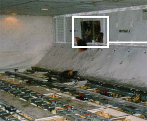
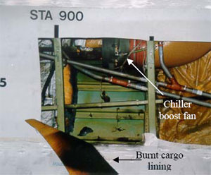
A hot spot was detected on the left side of the forward cargo bay at body station STA900, where the side wall lining was found to be heat affected. Removal of the lining revealed burned insulation blanket material, discolouration of the aircraft skin and burned/broken electrical wires that powered the forward galley chiller boost fan situated in the area (see Fig 1). As the fire was no longer evident, ground engineers isolated the chiller boost fan electrical circuit and towed the aircraft clear of the runway.

aair200203671_001.jpg
aair200203671_002.jpg
FIGURE 1: Forward cargo bay with expanded view of chiller boost fan location

Aircraft structural damage

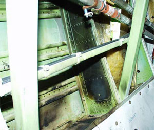
Non-destructive testing to check for cracking and conductivity of the aircraft skin adjacent to the affected area was carried out. No cracks were detected, however the conductivity test revealed three locations where the skin had been substantially affected by heat (see Fig 2). The most severely affected area required a temporary skin repair before the aircraft could be flown back to the operator's maintenance facility in the United Kingdom, where the heat-affected aircraft skin was replaced.

aair200203671_003.jpg
aair200203671_004.jpg
FIGURE 2: Heat affected areas

Sidewall lining and insulation blankets

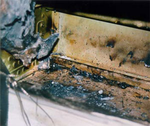
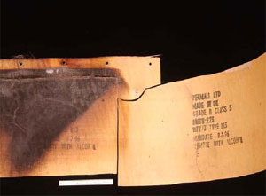
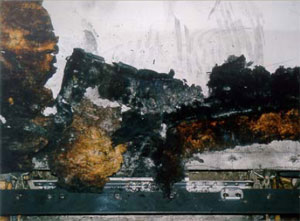
The fibreglass sidewall lining between STA880 to STA900 was visibly heat damaged with discolouration observed on the side facing into the cargo compartment. Inspection of the reverse side revealed burned layers of fibreglass confined to a localised area approximately 30cm x 45cm (see Fig. 3). The insulation blankets that lined the aircraft skin were made of a fibreglass core with a metallised TedlarTM film on one side and a MylarTM film on the other and had been subjected to localised heat and fire (see Fig. 4).

Samples of the sidewall lining and insulation blanket were sent to the United States of America, Federal Aviation Administration (FAA) technical centre and the aircraft manufacturer for analysis and testing.

aair200203671_005.jpg
aair200203671_006.jpg
FIGURE 3: Sidewall liningFIGURE 4: Insulation blanket

The examinations determined that both the sidewall lining and insulation blanket samples complied with the appropriate material specifications for aircraft use.

The flammability testing, conducted by the FAA, on samples of the insulation blanket included a vertical Bunsen burner test, which was mandated in Federal Aviation Regulation FAR 25.853 - Appendix F. The samples tested met the requirements, but due to their limited size, the result was not conclusive as to the integrity of the entire blanket.

The aircraft manufacturer's tests revealed contamination on the insulation blanket samples. This contamination consisted of environmental dust, fibres and corrosion inhibiting compound. These contaminants were consistent with general contamination found during evaluations of other in-service insulation blankets and were considered to be normal.

The aircraft manufacturer's 'flame propagation cotton swab tests' found areas on the blanket samples that were self-extinguishing while other areas showed "flame propagation uncharacteristic of that expected for new insulation blankets". It was unknown whether contamination, in-service ageing, or heat exposure, or a combination of these, altered the blanket's flame propagation characteristics.

Boost fan system

A galley chiller boost fan system was installed in the aircraft to provide forced air circulation over the forward galley chiller units increasing their cooling efficiency. The system incorporated a vaneaxial-type three-phase fan, powered by the aircraft's number 3 alternating current electrical system. Control power was supplied by the aircraft's direct current electrical system, with operation being automatic on selection of the galley chillers to ON. Circuit protection was provided by a 20 ampere circuit breaker and a cargo fire cutoff relay.

Chiller boost fan

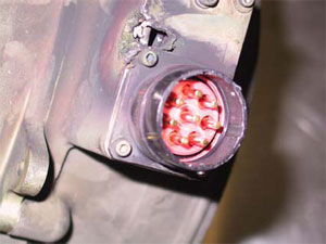
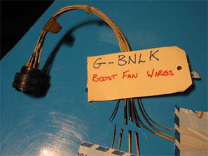
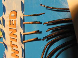
An inspection of the boost fan revealed a burn hole and sooting on its casing adjacent to the electrical terminal (see Fig. 5). The electrical wiring to the fan was found to have four of its seven wires broken, with all of the wires displaying sooting discolouration (see Fig's. 6 and 7). The soot marks corresponded to those on the fan casing and when positioned together, revealed that the wires had separated at a point adjacent to the corner of the electrical terminal. The failure of the wires produced electrical arcing, which melted the casing, resulting in the burn hole observed.

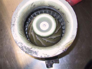
Further inspection found that all of the fan impeller blades had failed just above their roots (see Fig. 8). Neither the impeller nor the fan shroud showed signs of hard body impact damage.

aair200203671_007.jpg
aair200203671_008.jpg
FIGURE 5: Electrical terminalFIGURE 6: Broken wires
aair200203671_009.jpg
aair200203671_010.jpg
FIGURE 7: Sooting evidentFIGURE 8: Fan impeller blades failed

Technical examination of the fan found that the impeller was made from a moulded resin material. There was no evidence of any pre-existing defects or cracking found on the blade fracture surfaces. However, a number of blades showed breakage of a curved lip of material from their forward corner. This condition was consistent with overload fatigue possibly due to the blade tips contacting the fan shroud. Such a condition may have occurred prior to the blades total failure. The inside surface of the impeller was coated with a brown powder, determined to be primarily iron oxide.

The aluminium alloy shroud contained several circumferential wear marks that were adjacent to the impeller blade path. Although there were random scratches, no evidence of gouging or penetration of the shroud skin was found.

Further disassembly of the fan revealed wear on the electrical motor stator, indicating that it had been subjected to armature rubbing. The armature did not display similar wear patterns. Rubbing of this nature usually occurs as a result of bearing failure or excessive wear, leading to armature oscillations. For the full technical report see Attachment 'A'

Chiller boost fan service history

The chiller boost fan entered service in 1994, with the last overhaul being in June 2000, after removal from service because of electrical failure. The maintenance records for that overhaul stated: "Unit noisy due worn bearings, all other parameters ok. Reported defect not confirmed. Disassembled, cleaned and inspected, bearings renewed, unit reassembled and tested to spec". The fan was then fitted to the incident aircraft on 2 August 2000. No subsequent maintenance was recorded.

Chiller boost fan circuit breaker and electrical relay

The installed circuit breaker was a 20 ampere three-phase, push-pull high performance, trip free type, designed for aircraft installations. It's design allowed for increased amperage through the circuit for a specific time before tripping (breaking the circuit) and was used in large motor load applications where the inrush current would trip a standard circuit breaker. The length of time taken to cause the circuit breaker to trip varied according to the current it received. The aircraft manufacturer advised that "At 385 per cent or 400 per cent [load rating], this breaker will trip between 2.3 to 10 seconds". This prevented aircraft electrical power surges from "nuisance" tripping of the circuit breaker and rendering the boost fan inoperative.

A number of tests were conducted on the circuit breaker, including a 'load withstanding test'. This required the controlled increase in current through the circuit breaker, with time to trip recorded. This test was conducted at 105 per cent, 140 per cent and 200 per cent values, as per the manufacturers test procedures.

The installed relay was a 25 ampere, electromagnetic, three pole, single throw, normally open type. This was also subjected to a number of tests including 'Coil resistance', 'Coil hold and drop voltage' and 'Voltage drop and switching test across all three phases'.

These tests were performed under the supervision of the United Kingdom Air Accident Investigation Branch. Both components were found to comply with their operational specifications, with no adverse mechanical or operational functions found during the testing. As a result, both components were considered to be serviceable.

Quick Access Recorder

The aircraft's Quick Access Recorder (QAR) data was analysed by the Australian Transport Safety Bureau with the following information retrieved.

During climb the number 3 alternating current system showed a momentary increase in load from a nominal 31 per cent to 54 per cent, which equated to an increase in current draw of 57 amperes.

Four seconds later, the load was again recorded and had returned to the nominal 30 percentage range, where it remained for the rest of the flight.

Approximately 1 minute later the QAR recorded a forward cargo fire.

Approximately 3 minutes later, the first cargo fire bottle low quantity message appeared, indicating that extinguishant had been discharged successfully.

Other recorded data received from the aircraft's central maintenance computer (CMC) confirmed the arming of the fire bottles approximately 2 minutes after the fire warning and the discharging of the last two fire bottles after the aircraft landed.

Cargo fire detection/extinguishing system

The aircraft incorporated two dual loop smoke detectors in each cargo compartment. Air from throughout the compartment was drawn through the detectors and sampled. In normal operation, both loops must sense smoke for a fire warning to be activated. If the system detects a loop fault during self-test at aircraft power on, it would reconfigure to a single loop operation.

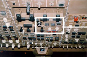
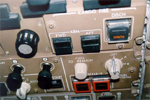
The cargo fire module located on the overhead instrument panel in the flight deck incorporated forward and aft compartment ARM buttons and a DISCH discharge button. On sensing smoke, the relevant ARM button, along with an EICAS message would be illuminated, alerting the crew of the fire. The crew must then push the ARM button in. This action disables electrical power to a number of circuits, including the galley chiller fan circuit. Extinguishing is then achieved by pressing the DISCH button (see Fig. 9).

aair200203671_011.jpg
aair200203671_012.jpg
FIGURE 9: Overhead instrument panel with expanded view of cargo fire panel

Four fire extinguisher bottles (A, B, C and D) service the cargo compartments, each having discharge lines to both the forward or aft compartments. On depression of the DISCH switch, bottles A and B discharge flooding the selected compartment with extinguishing agent. Bottles C and D are not discharged until 30 minutes later. If the aircraft reaches the ground before the 30 minutes are up, the bottles will discharge on touch down. The system was designed to give up to 180 minutes of discharge time.

Occurrence summary

Investigation number 200203671
Occurrence date 10/08/2002
Location 6 km N Sydney, Aero.
State New South Wales
Report release date 18/12/2003
Report status Final
Investigation type Occurrence Investigation
Investigation status Completed
Mode of transport Aviation
Aviation occurrence category Fire
Occurrence class Serious Incident
Highest injury level None

Aircraft details

Manufacturer The Boeing Company
Model 747
Registration G-BNLK
Serial number 24053
Sector Jet
Operation type Air Transport High Capacity
Departure point Sydney, NSW
Destination Singapore
Damage Minor

Saab SF-340B, VH-OLM

Safety Action

In consultation with the DECU repair vendor, the engine manufacturer has developed improved inspection and test procedures for field returned DECUs, which are specifically identified as `loss of torque signal' units.

The operator, operating as a new entity, has now altered its Saab 340B checklists to reflect the aircraft manufacturer's requirements for the operation of the auto-coarsen system during the Approach Checks.

Analysis

The reason for the left propeller feathering could not be conclusively established. Although some of the circumstances were consistent with an inadvertent auto-coarsen event, the cockpit indications reported by the crew were indicative of an engine failure.

Identification of a torque output defect in the occurrence DECU, indicated that a spurious torque signal output from that DECU may have precipitated an inadvertent auto-coarsen event. That outcome was consistent with DECU torque output anomalies implicated in inadvertent auto-coarsen events reported by the engine manufacturer. However, the crew's report that the power levers were below the 64 degree position, placing the auto-coarsen system in low mode, meant that there was no valid basis for the auto-coarsen system to operate in response to a spurious torque signal.

The successful test of the auto-ignition system immediately following the occurrence indicates that it was probably serviceable at the time of the occurrence. With the ignition system selected to NORM, the apparent failure of the auto-ignition may have been the result of the DECU parameters for auto-ignition operation not being exceeded. That would be consistent with an inadvertent auto-coarsen event.

The investigation was unable to determine the reason for the difference between the operator's procedures and the aircraft manufacturer's data with respect to when auto-coarsen should be selected. Selection of auto-coarsen at a later stage of the flight, for example, during the landing checklist (in accordance with the manufacturer's data) would have reduced the exposure to an inadvertent auto-coarsen event.

When tested following the occurrence, the FDR operated normally. During the occurrence, if the FDR had provided valid data it would have allowed independent corroboration of the information supplied by the parties involved in the occurrence. The reason for the lack of valid FDR data was not able to be determined.

Summary

The Saab SF340B aircraft was being operated on a scheduled passenger flight from Dubbo, NSW to Sydney. The crew reported that, during the descent into Sydney and while passing flight level 110, they selected the auto-coarsen system ON. After passing through 7,000ft AMSL, the aircraft suddenly yawed to the left and the left propeller feathered. The crew reported that they immediately noticed illumination of master warning and caution annunciations consistent with a left engine failure. A scan of the engine instruments confirmed that the left engine appeared to have shut down, with the engine torque and fuel flow indications at zero. At the time of the apparent engine shutdown the aircraft was under autopilot control. The crew reported that they were not operating any engine controls and that the power levers were positioned below the 64 degree position. The crew reported that the aircraft's auto-ignition system, which was armed when the ignition system was selected to NORM at engine start, did not operate throughout the incident.

The left engine was secured, and the crew informed the flight attendant and passengers of the situation. The crew declared a PAN to air traffic control, reporting an engine shutdown, and a local standby was declared. The crew elected not to attempt an engine restart due to the aircraft's proximity to the airport, and an uneventful one-engine inoperative landing was conducted.

Immediately following the incident, the operator's maintenance personnel carried out operational checks of the left engine. During those checks the engine and its auto-ignition system were found to operate normally.

An investigation into the incident, carried out by the operator, resulted in the removal of the left engine's hydromechanical unit (HMU) and the digital electronic control unit (DECU) for examination. The aircraft's fuel system was also extensively inspected with no defects or anomalies detected. The aircraft was then returned to service and the problem had not recurred in the 15 months following the incident.

The operator forwarded the removed HMU and the DECU to the component repair vendor. That examination found no problems with either component that would have contributed to the incident and both components were returned to the operator as serviceable items. The DECU was subsequently fitted to another aircraft in the operator's fleet. A short period after fitment, the unit was again removed following engine `torque fluctuation' problems on that aircraft and the component was again returned to the component repair vendor for examination. During that examination, a fault with `stressed' solder joints on a central processing unit board within the DECU was discovered and corrected. Several internal microcircuits were also replaced.

The aircraft was equipped with an engine ignition system that, when selected to NORM, automatically provided `flameout protection', or auto-ignition. The DECU sensed the rate of engine deceleration, comparing it to an internally programmed `rate of change' or `flameout schedule', and at a predetermined figure energised the ignition system for 7.5 seconds. This was indicated by illumination of a white ignition light on the flight status panel. The ignition was shut off when the gas generator speed decreased below 62% to prevent a `sub-idle relight'. The pilot in command reported that on the previous sector, the auto-ignition light had illuminated for a period of about 4 seconds during the descent, for no apparent reason.

The auto-coarsen system was designed to automatically feather a propeller in order to achieve a rapid reduction in propeller windmilling drag in event of an engine failure during takeoff, approach and go-around. The auto-coarsen system operated in a high or low mode depending on whether the power levers were above 64 degrees (high) or below 64 degrees (low). The active mode was indicated by the illumination of an annunciator positioned on the flight status panel. There were no markings on the power lever control quadrant to indicate the 64 degree position to the crew. The auto-coarsen system monitored a number of parameters including power lever angle and when in high mode, engine torque. The engine torque signal was provided by the DECU. During an auto-coarsen event, where an engine failure is not the reason for the event, the engine can continue to operate at low power with corresponding fuel flow, inter-turbine temperature (ITT), oil pressure and temperature indications.

The engine manufacturer reported to the ATSB that they had received several field reports that identified where an internal failure within the DECU had resulted in an intermittent loss of the torque signal output from an engine. The engine manufacturer further reported that, when allied with conditions of power lever position and engine parameters that are pre-programmed into the auto-coarsen computer, an intermittent loss of torque signal could result in the auto-coarsen computer mistakenly detecting an engine failure, triggering an inadvertent propeller auto-coarsen event.

The engine manufacturer reported that they had recently become aware that their standard acceptance test procedures (ATP), performed on DECU's following maintenance, had not always been successful in isolating intermittent loss of torque signal faults. They advised that they had improved the ATP procedures for DECU's that had been identified as `loss of torque signal' units. The occurrence DECU had not undergone the improved ATP inspection when it had been returned for examination following the occurrence.

The standard operating procedures to be followed by flight crews were detailed in the operator's Aircraft Operations Manual. These procedures contained the flight checklists to be followed in normal, abnormal and emergency situations. The aircraft manufacturer issued Revision 32 of the Saab 340B Aircraft Operations Manual in February 2001. That revision modified the normal checklist, deferring selection of auto-coarsen from the transition checklist to the landing checklist in order to minimise the time with auto-coarsen on, thus reducing the probability for an inadvertent auto-coarsen event. At the time of the occurrence the operator's checklists specified that auto-coarsen be selected to ON at FL110, as part of the transition check. The reason the operator's checklist was not revised to reflect the manufacturer's data was not available due to subsequent organisational changes.

The Flight Data Recorder (FDR) information from the aircraft was analysed by the ATSB to assess the operating parameters of the engine during the incident. That analysis revealed that approximately 37 minutes after take-off, with the aircraft in cruise flight, the flight data recorder had begun to record invalid information. This resulted in no useful data being available from the FDR for the remainder of the incident flight, a period of about 24 minutes. An examination of the aircraft's flight recorder system carried out by the operator during post incident system checks found no reason for the malfunction.

Occurrence summary

Investigation number 200203655
Occurrence date 07/08/2002
Location 37 km WSW Sydney, Aero.
State New South Wales
Report release date 20/07/2004
Report status Final
Investigation type Occurrence Investigation
Investigation status Completed
Mode of transport Aviation
Occurrence class Incident
Highest injury level None

Aircraft details

Manufacturer Saab Aircraft Co.
Model 340
Registration VH-OLM
Serial number 205
Sector Turboprop
Operation type Air Transport Low Capacity
Departure point Dubbo, NSW
Destination Sydney, NSW
Damage Nil

Boeing 737-800, VH-VXD

Safety Action

Local safety action

The B737 operator amended controlled rest procedures to require both crew members to be on duty when a change in level was conducted.

ATSB safety action

The ATSB issued Safety Advisory Notice (SAN) 20010244 to the aviation industry on 2 May 2002. That notice stated:

The Australian Transport Safety Bureau alerts all operators in the transport industry, particularly those involved in extended-hours operations, to the possibility of crew members suffering sleep inertia and suggests that operators take steps to mitigate the effects of sleep inertia. The steps should not include subjecting employees to sleep deprivation.

The ATSB issued SAN20010245 to the Civil Aviation Safety Authority on 15 April 2002. That notice stated:

The Australian Transport Safety Bureau suggests that the Civil Aviation Safety Authority alert all aviation industry operators to the possibility of sleep inertia impairing performance, particularly that of flight and maintenance crews.

The ATSB also issued SAN20020035 to the Civil Aviation Safety Authority on 15 April 2002. That notice stated:

The Australian Transport Safety Bureau suggests that the Civil Aviation Safety Authority ensure that operators have strategies in place to mitigate the effects of sleep inertia as part of their fatigue management systems.

Analysis

The co-pilot had less than nine hours of interrupted sleep during the 48 hours preceding the incident. That small period of sleep suggests that the co-pilot may have been fatigued at the time of the incident despite feeling adequately rested. Fatigue may lead to impaired physical and mental performance in people and may explain why, when the controller requested confirmation of the aircraft's level, the co-pilot relied on his memory rather than performing the more demanding task of confirming the aircraft's level by looking at the altitude indicator.

Within a short time of waking from the period of controlled rest, the co-pilot had received a handover briefing and assumed control of the aircraft. Despite reporting the correct level (FL390) to the Bourke sector controller during a change of radio frequency, the co-pilot subsequently reported an incorrect level (FL370) a few minutes later with the APOMA position report.

It is likely that the co-pilot was suffering from the cumulative effects of fatigue and sleep inertia that resulted in the incorrect level being passed with the position report. The occurrence highlights that an understanding of fatigue and how to manage it are important defences to a human limitation.

Despite the aircraft being at flight levels that provided 2,000 ft vertical separation, the Bourke sector controller's provision of mutual traffic information to both the co-pilot and the pilot of the B747 was warranted. At that stage, the pilot reported information provided to the controller indicated that a separation standard was not being applied to the aircraft. The traffic information would have assisted both crews to assess the potential for conflict and would have provided a basis for pilot-initiated avoiding action. Under the circumstances, the provision by the controller of a safety alert that would have included a recommended action to either turn or to climb/descend, as well as the provision of traffic information, may have been a better option. That action would have ensured that the pilots clearly understood that the aircraft were in close proximity and at the same level, based on the reports provided to the controller.

Summary

The co-pilot of a Boeing 737-800 (B737) en route from Perth to Brisbane on air route T91 reported maintaining flight level (FL) 390. He later reported maintaining FL370 at APOMA, located 140 NM north-northeast of Broken Hill, at 0501 EST. The Bourke sector controller in the Melbourne Air Traffic Control Centre requested the co-pilot to confirm the aircraft's level. The co-pilot replied that the aircraft was at FL370. A Boeing 747 (B747) maintaining FL370 was on a crossing route and estimated APOMA at 0503, two minutes after the B737. To be separated, aircraft at the same level on intersecting tracks required 15 minutes between their respective intersection estimates. The controller issued traffic information to the co-pilot of the B737 and to the crew of the B747.

At a subsequent position report the pilot in command (PIC) of the B737 overheard the co-pilot report the aircraft's level as FL370 and corrected the error. Later analysis of the flight data recorder of the B737 confirmed that the aircraft had maintained FL390. There was no infringement of separation standards.

The B737 operator had an approved procedure for the `controlled rest' of flight crew members while remaining on the flight deck. Controlled rest was recognised by the operator as `an effective method of improving levels of crew alertness for critical phases of flight'. There were a number of guidelines concerning the use of the procedure, including:

  1. It was not to be used on sectors of less than two hours duration.
  2. It was only to be used during the cruise phase of flight.
  3. Periods of controlled rest were not to exceed 30 minutes per crew member per sector.
  4. An additional 10 minutes was required after the period of controlled rest before a crew member resumed flight deck duties.

At 0213, the B737 departed Perth and was climbed initially to FL370. The flight plan advised an intention to change level to FL390 by BEZZA, a position about 340 NM west of Leigh Creek. At about 0405, the co-pilot requested and was approved by the PIC to take a controlled rest. At 0416, the PIC requested and was approved by the Melbourne Centre controller for the aircraft to climb to FL390. At 0421, the PIC reported maintaining FL390 to the Melbourne Centre controller. At about 0440, the co-pilot ceased the controlled rest and was briefed by the PIC in the next five minutes before assuming control of the aircraft. The briefing included the level of the aircraft. The PIC then commenced a period of controlled rest until about 0520. On initial contact with the Bourke sector controller at 0458, the co-pilot reported that the aircraft was maintaining FL390.

The roster for the 48-hour period preceding the incident required the crew to commence work at about 1900 two days before the incident and to operate a flight from Brisbane to Perth, arriving in Perth at approximately 0120. They spent the remainder of that day at their leisure prior to departing Perth for Brisbane on the incident flight at 0213 the following morning. That departure time required the crew to report for duty at approximately 0100.

On the morning of the Brisbane to Perth flight the co-pilot awoke at 0530 and had a 30-minute nap during that day. The co-pilot slept for approximately 6.5 hours after arriving in Perth, had a 90-minute nap late that afternoon and 30 minutes of controlled rest during the flight to Brisbane. Those periods of sleep accumulated to about nine hours during the 48-hour period. The co-pilot later reported that he felt rested prior to commencing the Perth to Brisbane flight.

Fatigue is recognised as a primary cause of transport accidents throughout the world as a result of reduced or impaired mental and/or physical performance following inadequate rest.

One component of fatigue relevant to the transport industry is sleep inertia. That phenomenon refers to the period of mental dullness or sluggishness immediately after awakening. During a period of sleep inertia people demonstrate the outward signs of being awake but are not mentally awake. Research suggests that it may take approximately 30 minutes after awakening for the effects of sleep inertia to fully dissipate.

The co-pilot was newly rated on the B737-800 and reported that he had found scanning the altitude indicator in that aircraft series took longer and required additional conscious effort. The co-pilot reported that when providing the aircraft's level, in response to the Bourke sector controller's query, he had relied on his memory of the information in the position report rather than re-checking the altitude indicator on the flight instrument display.

The Bourke sector controller twice requested confirmation of the flight level from the co-pilot of the B737 and was advised on both occasions that the level was FL370. At that stage, the controller passed traffic information to the co-pilot about the B747 at FL370 on the crossing route. The controller also passed traffic information on the B737 to the pilot of the B747. The co-pilot of the B737 later reported that at that time he was unsure why the controller had issued the traffic information as he could see the B747 displayed on the B737's Traffic Alert and Collision Avoidance System (TCAS) behind and 2,000 ft below his aircraft.

The Manual of Air Traffic Services (MATS) section covering safety alerts (Section 5.1.13) included the following:

'A safety alert shall be issued to an aircraft when a controller is aware the aircraft is in a situation which is considered to place it in unsafe proximity to terrain, obstructions, or other aircraft. The controller must remain vigilant for the development of such situations and issue a safety alert when the situation is recognised.

Conditions such as workload, traffic volume, the quality/limitations of the radar system, and the available lead time to react are factors in determining whether it is reasonable for the controller to observe and recognise such situations.

The issuance of a safety alert is a first priority.

When a controller is aware that an aircraft is in unsafe proximity to another aircraft, a safety alert shall be issued as follows:

"(Callsign) TRAFFIC ALERT (position of traffic if time permits), [SUGGEST] TURN LEFT / RIGHT (specific heading, if appropriate), and / or [SUGGEST] CLIMB / DESCEND (specific altitude if appropriate), IMMEDIATELY".

When a safety alert is directed to traffic not receiving a separation service, advice to turn or change level shall be prefixed with the word SUGGEST'.

Occurrence summary

Investigation number 200203641
Occurrence date 08/08/2002
Location APOMA, (IFR)
Report release date 03/12/2002
Report status Final
Investigation type Occurrence Investigation
Investigation status Completed
Mode of transport Aviation
Aviation occurrence category Air-ground-air
Occurrence class Incident
Highest injury level None

Aircraft details

Manufacturer The Boeing Company
Model 737
Registration VH-VXD
Sector Jet
Operation type Air Transport High Capacity
Departure point Perth, WA
Destination Brisbane, QLD
Damage Nil

Piper PA-28-161, VH-XFY

Analysis

In VMC within a GAAP CTR, the pilot in command was primarily responsible for ensuring separation from other aircraft. Consequently, despite the IFR category of the Duchess, the instructor and the pilot in that aircraft were required to maintain a lookout for other aircraft until leaving the CTR. The instructor in the Duchess was probably distracted by the coaching and assessing role such that he did not appreciate the potential for conflict and therefore did not look out, in the required direction, for the other aircraft.

The instructor in the Cherokee saw the Duchess on the runway but did not take action to maintain sight of that aircraft after it was obscured by the Cherokee's engine cowl. Had the instructor kept sight of the Duchess the occurrence was unlikely to have happened.

The inbound track adopted by the pilot of the Cherokee made it more likely that it would conflict with IFR aircraft departing the CTR on climb to an altitude above 2,000 ft. The radar information indicated that some pilots of inbound aircraft enter the circuit via early downwind instead of crosswind.

Pilots operating in GAAP CTRs need to understand that the practice of entering the CTR via wide or oblique crosswind reduces the safety benefit of GAAP entry procedures. Also, that maintenance of situational awareness is a precursor to being able to attend to areas of potential conflict adequately, when operating at GAAP aerodromes.

The Duchess pilot was cleared to operate in the CTR such that the procedural defences used to minimise the likelihood of conflict between arriving and departing aircraft were negated. The situation could have been assisted by the provision of traffic information by ATC to the pilot of the Duchess and/or the Cherokee pilot.

Summary

As the Piper PA-28-161 (Cherokee) tracked from the 2RN inbound reporting point, which was 5.5 NM southwest of Bankstown Airport, via crosswind at 1,500 ft to runway 29, the instructor pilot saw a Beech Aircraft Corporation 76 (Duchess) pass close in front, tracking from right to left and on climb. The instructor pilot in the Cherokee turned the aircraft to the right to avoid the Duchess. Later analysis of the recorded radar information indicated that the two aircraft had passed about 150 m apart while at the same altitude.

Pilots of aircraft operating on Bankstown airport or within the control zone (CTR) were required to operate in accordance with General Aviation Airport Procedures (GAAP). The Visual Flight Rules (VFR) Flight Guide stated that GAAP catered for high-density operations in visual meteorological conditions (VMC). In VMC within a GAAP CTR, the pilot in command was primarily responsible for ensuring separation from other aircraft. Air Traffic Control (ATC) controlled runway operations with landing and take-off clearances and facilitated a high movement rate by providing traffic information and/or sequencing instructions.

The GAAP procedures were published in the Bankstown Visual Pilots Guide and the Aeronautical Information Publication (AIP) En Route Supplement Australia (ERSA). Bankstown procedures required pilots of aircraft to enter the CTR via specific reporting points, including 2RN, at 1,500 ft when runway 29 was the assigned runway (Figure 1). Pilots of aircraft operating out of the CTR in the runway 29 direction were required to depart via upwind and to maintain 1,000 ft until leaving the CTR. That procedure provided 500 ft vertical spacing between arriving and departing aircraft. Runway 29 Right was the nominated arrivals runway.

The Cherokee was on a VFR training flight with a flying instructor and student pilot. The student pilot was flying the aircraft as it tracked inbound to Bankstown Airport while the instructor briefed the student on geographical points. The instructor later reported that he did see the Duchess departing but it became obscured by the engine cowl of the Cherokee.

The Aeronautical Information Publication (AIP), used by pilots operating flights under the Instrument Flight Rules (IFR), stated that `arriving IFR aircraft which are visual outside the GAAP CTR, and can continue visually, must operate VFR within the CTR'. A pilot operating an IFR aircraft visually would only receive a traffic information and a sequencing service, and would not be separated from other traffic. The AIP further stated that `Departing IFR aircraft must operate VFR within the GAAP CTR until encountering Instrument Meteorological Conditions (IMC) or leaving the GAAP CTR, whichever is the sooner'. When aircraft are operating in conditions less than VMC, ATC will provide separation within the GAAP CTR. The weather at the time was VMC.

The Duchess was flown by a pilot on an instrument rating flight test monitored by a flying instructor. The pilot was conducting a Bankstown One departure on climb to 3,000 ft. The pilot departed from runway 29 Centre on a heading of 290 degrees M and had been instructed to report to the aerodrome controller (ADC) when the Duchess had passed 2,000 ft, the upper limit of the CTR. The instructor and the pilot in the Duchess did not see the Cherokee.

The instructor in the Cherokee monitored the ADC frequency as the aircraft approached 2RN. At 0214:00 the ADC issued departure and runway entry instructions to the pilot of the Duchess. About 20 seconds later the pilot of the Cherokee reported at 2RN at 1,500 ft and was subsequently instructed by the ADC to join via crosswind for runway 29. At 0214:50 the ADC issued a take off clearance to the pilot of the Duchess. The instructor in the Cherokee recalled hearing the take off clearance for the Duchess and saw that aircraft when it was on the runway but lost sight of it behind the engine cowl of the Cherokee. At 0217:10 the instructor in the Cherokee reported to the ADC that the aircraft was `joining downwind and that they had just seen the Duchess'. The ADC acknowledged that report and at 0217:34 the pilot of the Duchess reported passing 2,000 ft.

The altitude of the Duchess could not be accurately ascertained, as the Mode C function of that aircraft's transponder was not activated. The Mode C function for the Cherokee was activated and the recorded radar information showed that the aircraft had maintained 1,500 ft until established on downwind. The instructor in the Duchess later estimated that the aircraft would have been at about 1,500 ft at the point where the tracks intersected.

The radar track of the Cherokee showed that the pilot had tracked directly from 2RN to an early downwind position (Figure 2 - Track 1). That track was about 0.5 NM west of the recommended crosswind track (Figure 2 - Track 2). The aircraft tracks recorded during a 4-hour period on the day of the occurrence showed that there were a number of other pilots who tracked west of the recommended crosswind track, depicted in the Bankstown Visual Pilots Guide, when they entered the circuit area.

The intention of the entry procedure (Figure 1) was to have pilots enter the circuit, via crosswind, in a position to sight aircraft on the runway, aircraft departing, and other aircraft in the circuit. Crossing the extended runway centreline at 90 degrees also minimised the potential for arrival/departure conflicts as departing aircraft would generally have been airborne for only a short period and consequently would not have climbed to the 1,500 ft inbound altitude. Aircraft climb performance is subject to various factors, including aircraft type and load but generally the closer an inbound aircraft tracks to the threshold of a departure runway the more likely that there would be some vertical spacing between it and departing aircraft.

Occurrence summary

Investigation number 200203573
Occurrence date 17/07/2002
Location 2 km NW Bankstown, Aero.
State New South Wales
Report release date 20/03/2003
Report status Final
Investigation type Occurrence Investigation
Investigation status Completed
Mode of transport Aviation
Aviation occurrence category Near collision
Occurrence class Incident
Highest injury level None

Aircraft details

Manufacturer Piper Aircraft Corp
Model PA-28
Registration VH-XFY
Serial number 28-16074
Sector Piston
Operation type Flying Training
Departure point Bankstown, NSW
Destination Bankstown, NSW
Damage Nil

Aircraft details

Manufacturer Beech Aircraft Corp
Model 76
Registration VH-JWW
Serial number ME-389
Sector Piston
Operation type Unknown
Departure point Bankstown, NSW
Destination Unknown
Damage Nil

British Aerospace Plc BAe 146-100, VH-NJR

Safety Action

Local Safety Action

As a result of its investigation the operator has:

  1. Carried out a fleet inspection that did not find evidence of any other coupling failures.
  2. Accelerated the scheduled program on its remaining fleet for the implementation of all the manufacturers service bulletins related to proper sealing of the hydraulic bay.
  3. Advised the ATSB that all manufacturer's advised modifications have since been incorporated on the occurrence aircraft.
  4. Recommended company procedural changes, including whenever possible using able-bodied passengers to assist at the base of slide during an evacuation and consideration of stand down of crews following an emergency.

Significant Factors

  1. The leak in the hydraulic coupling led to the escape of hydraulic mist.
  2. Inadequate sealing of the hydraulic bay allowed the hydraulic mist to enter the passenger cabin.

Analysis

As a result of the coupling leak, hydraulic vapours entered the passenger cabin, affecting passengers. Replacement of the coupling 'o' ring temporarily stopped the leak.

Following the subsequent leak an NDT report identified the overload failure of the coupling threads, which was consistent with over-tightening. This condition may have been present during the initial hydraulic leak but was masked by the replacement of the 'o' ring seal.

Both the pilot and a cabin crewmember considered it safe to act contrary to company emergency procedures. However, these actions had the potential to result in flight crew incapacitation through exposure to fumes.

The assistance of the off-duty cabin crewmembers contributed to the timely and safe evacuation. However, the use of additional able-bodied passengers to clear others from the slide may have further reduced the possibility of injury to passengers and crew.

Although crewmembers had conducted an evacuation and some had inhaled fumes, both flight and cabin crew continued the tour of duty without rest. Following abnormal events, the ability of crewmembers to carry out their safety duties for the care of passengers on subsequent flights may be adversely affected due to the effects of the event.

Summary

During taxi for take-off, the crew of the BAe146-100 aircraft noticed a 'yellow' hydraulic system 'low quantity' warning light on the aircraft's master warning system panel.

At approximately the same time, a cabin crewmember opened the flight deck door to alert the flight crew to the presence of fumes in the cabin. Passengers and two off-duty cabin crew reported a slowly moving white haze, low on the right side of the passenger cabin, in the vicinity of row 6. The haze was acrid and transparent and caused coughing and breathing difficulties.

An off-duty cabin crewmember also went to the flight deck and told the captain that the situation in the cabin had worsened, that there was smoke on the right side of the cabin and that passengers were having difficulty breathing. Because of the urgency of the report the pilot stopped the aircraft on a taxiway and instructed the cabin crew to prepare to evacuate passengers through the left doors. After shutdown procedures were completed, he ordered the evacuation.

The two operating cabin crewmembers opened the forward and rear left doors and deployed the escape slides. The two off-duty cabin crewmembers evacuated first, one through each door, to assist passengers at the base of the slides.

A passenger reported that cabin crew who stood at the aircraft doors to control the evacuation and block access to the right doors were out of view of the cabin. Therefore, the cabin crew could not see other passengers attempt to retrieve cabin baggage; an action that clogged the aisle and slowed progress to the exits. However, cabin crewmembers reported that cabin baggage did not delay the evacuation.

A cabin crewmember at the base of a slide reported that early in the evacuation, some passengers struck others that had not yet cleared the slide. Some fell as they reached the slide base and she lifted people to avoid a bank-up and the possibility of injury. Later, the evacuation proceeded in a more orderly manner. Cabin crew reported that they did not request assistance from able-bodied passengers during the evacuation.

Medical assistance

The airport Rescue Fire Fighting Services attended shortly after the evacuation was completed. They offered medical assistance and administered oxygen to two passengers. Medical assistance was also offered to passengers and crew on arrival at the airport terminal. None of the passengers requested medical attention.

Aircraft crew actions

Company emergency procedures required flight crew to don oxygen masks at any time that smoke or fumes were detected in the cabin. The procedures also required the flight deck door to remain closed to avoid flight crew incapacitation from fumes.

Both the pilot and the cabin crewmember that opened the door to speak to the flight crew reported that they were aware of the emergency procedure requirements. However, the pilot reported that the flight crew did not don oxygen masks as there were no fumes in the area and because the urgency of the cabin crew messages conveyed the need for an immediate evacuation. The cabin crewmember reported that it was quicker to open the flight deck door and safe to do so as there were no fumes in the area.

Cabin crew who had inhaled vapours, or who had assisted passengers off the escape slide, reported that during the continued tour of duty they suffered effects that included extreme tiredness, sore muscles and minor throat and chest problems.

Hydraulic system

Two independent systems provided hydraulic power to the aircraft flight controls and landing gear. These hydraulic systems were designated 'green' (left) and 'yellow' (right).

The power generation components were housed in the hydraulic bay, situated immediately forward of the main landing gear bay, below the forward rows in the passenger cabin. A light on the flight deck instrument panel provided a low hydraulic quantity warning when the fluid level fell below the operating level.

An inspection by the operator found that a leak in a hydraulic coupling allowed fluid under pressure to escape as vapour into the hydraulic bay and enter the passenger cabin via gaps in the sidewall lining. The 'o' ring seal for the coupling was replaced and the leak stopped. After a number of subsequent flights the coupling leak re-occurred. On closer inspection it was found that the coupling had a crack along its threads. The coupling was replaced.

The company reported that a subsequent Non Destructive Test (NDT) examination of the cracked coupling revealed that the coupling had failed through the bottom of a thread due to overload, which was consistent with having been done up too tightly.

Hydraulic equipment bay sealing

The aircraft manufacturer had generated three service bulletins that either required or recommended remedial action to improve sealing between the hydraulic bay and the passenger cabin. A zonal inspection was also conducted in the area at regular intervals.

At the time of the occurrence the operator had incorporated the first two service bulletins and had scheduled, but had not commenced, the third.

Occurrence summary

Investigation number 200203243
Occurrence date 22/07/2002
Location Brisbane, Aero.
State Queensland
Report release date 08/05/2003
Report status Final
Investigation type Occurrence Investigation
Investigation status Completed
Mode of transport Aviation
Aviation occurrence category Hydraulic
Occurrence class Incident
Highest injury level Minor

Aircraft details

Manufacturer British Aerospace
Model BAe 146
Registration VH-NJR
Serial number E 1152
Sector Jet
Operation type Air Transport High Capacity
Departure point Brisbane, QLD
Destination Alice Springs, NT
Damage Minor