Collision with terrain

Collision with terrain involving Aquila AT01, VH-OIS, Coombing Park Airstrip, 27 km south of Orange, New South Wales, on 4 November 2020

Final report

Report release date: 04/05/2023

Executive summary

What happened

In the afternoon of 4 November 2020, a training flight was conducted in an Aquila AT01, registered VH‑OIS (OIS) which departed Bankstown Airport with a Grade 1 flight instructor and a student onboard. The flight was conducted to assess the readiness of the student to complete the commercial pilot licence flight test for aeroplanes. The flight continued normally, proceeding to Coombing Park Aeroplane Landing Area (ALA), where the student demonstrated the conduct of a precautionary search, an expected exercise during this flight. However, following the precautionary search, a touch‑and‑go was performed. During the subsequent climb away from the runway, the aircraft collided with terrain. Both pilots received fatal injuries.

What the ATSB found

The ATSB found that pre-flight planning was likely not performed to identify if Coombing Park ALA was suitable for flight training operations. This placed more importance on the conduct of the precautionary search to identify the rising terrain hazard in the overshoot area of the runway. The precautionary search was conducted at a height and position that likely made assessing the hazard less effective, leading to the pilots deciding to conduct a touch-and-go landing and take-off toward the rising terrain beyond the runway end. Further, the take-off was conducted on an uphill slope with a probable tailwind. A standing take-off in the more favourable reciprocal direction would likely have cleared all obstacles and terrain.

Although the touch-and-go was typical of those conducted by the student, it likely used more runway than if a standing take-off was conducted, leading to the aircraft becoming airborne further along the runway, and closer to the rising terrain. Consequently, although the aircraft was likely performing normally, the aircraft had insufficient performance to outclimb the rising terrain in any direction once established on the initial climb after take-off.

The ATSB also found that the operations manual used for flight training that was based on the CASA sample operations manual allowed the use of any aerodrome (including ALAs) in the Enroute Supplement Australia to be used, although these were not assured to any operational standard. Further, the recommendations contained in CASA guidance CAAP 92-1(1) (although subsequently replaced by AC 91-02 as noted below) did not provide assurance that an aircraft would be able to outclimb rising terrain after take-off more than 900 metres from the runway end.

What has been done as a result

CASA advised that legislation and guidance relating to obstacle clearance in the approach and take-off areas of ALAs was introduced on 2 December 2021. Included in these changes were the replacement of CAAP 92-1(1) with Advisory Circular AC 91-02 titled ‘Guidelines for aeroplanes with MTOW not exceeding 5,700 kg – suitable places to take-off and land’ (the AC).

In contrast to CAAP 92-1(1), the AC included guidance for a pilot to consider and be aware of ‘lateral transition areas’ and ‘obstacles in the approach and climb-out flight paths’, in deciding if an aerodrome is suitable for operations. Further, the introduced regulations require that pilots ensure that the aeroplane has the performance to clear all obstacles by a safe margin until at the minimum height for flight.

Safety message

This investigation shows that the lift-off location following a touch-and-go is more variable and complex to predict than a standing take-off. In this case, the touch-and-goes conducted throughout the flight consistently used more runway than a standing take‑off. This contributed to the aircraft lifting off from a point where the available climb performance of the aircraft was not sufficient to outclimb the rising terrain. This characteristic is particularly important for flights to unfamiliar aerodromes, where the aerodrome characteristics should be considered to confirm if a touch‑and‑go is feasible, particularly for uncertified aerodromes. Additionally, as was the case here, the runway slope, wind and rising terrain at one runway end may mean that the optimal landing and take-off directions are in opposing directions, which cannot be achieved when conducting a touch-and-go.

The investigation also highlights the value of following operator’s procedures as an important risk control to aid planning and in-flight decision making. For this accident, the operator’s procedures did not allow landings to be conducted at the aerodrome where the accident occurred. This meant that the execution of the precautionary search was one of the last remaining defences to identify the rising terrain hazard during take-off, which was ineffective.

Operators should also be aware that aerodromes meeting the recommendations in the CASA guidance publication CAAP 92-1(1) (now obsolete) are not assured that an aircraft will be able to successfully climb away after take-off more than 900 metres past the runway end. The new performance-based recommendations of AC 91-02 now require operators to consider obstacle clearance beyond 900 metres. Flight training operators should also note that there are no standards for ALAs (listed in the ERSA as uncertified aerodromes). The published data for these uncertified aerodromes are potentially incomplete or inaccurate, including obstacle information. This means that for take-off from these aerodromes, the new guidance requires pilots and operators to know the climb gradient needed to clear all obstacles by a safe margin until the aeroplane reaches the minimum height for flight.

Summary video


The occurrence

Pre-flight and departure from Bankstown

In the afternoon of 4 November 2020, a training flight was conducted in an Aquila AT-01 aeroplane, registered VH‑OIS (OIS) between Bankstown Airport and Orange Airport, New South Wales (Figure 1). On board were a Grade 1 flight instructor (the instructor) employed by Soar Aviation (Soar), and a student (the student) of Soar. This flight was required by Soar to assess the readiness of the student to complete the Commercial Pilot Licence (Aeroplane) (CPL(A)) flight test administered by the Civil Aviation Safety Authority (CASA).

Figure 1: Flight path of VH-OIS and accident location
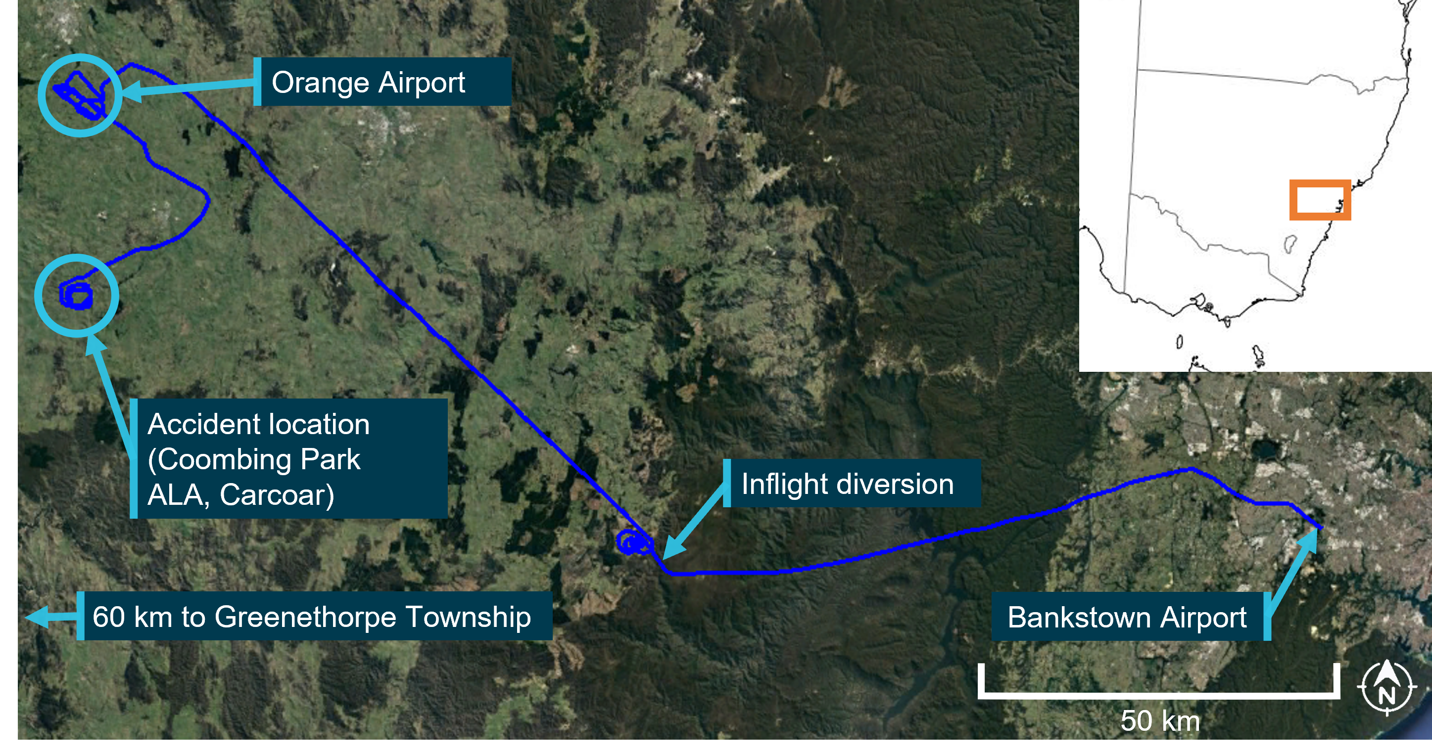
Figure 1: Flight path of VH-OIS and accident location

Source: Google Earth and Geoscience Australia, annotated by ATSB.

Automatic Dependent Surveillance Broadcast (ADS-B) data transmitted by OIS (the flight data)[1] indicated the aircraft started to taxi to a run-up[2] bay adjacent to Bankstown Airport runway 29R at 1419. The aircraft remained in the bay for about 5 minutes then, following engine run‑ups, the pilots[3] taxied OIS toward the runway 29R threshold, with take-off commencing at 1431 followed by an upwind[4] departure.

After departing the Bankstown Airport airspace, OIS initially tracked toward the west‑north‑west before turning left onto a west-south-westerly track about 19 km from Bankstown Airport, towards the planned track to Greenethorpe Township, about 220 km away. OIS continued tracking toward Greenethorpe until 1507, when the pilots turned right, tracking north-west toward a grassed area adjacent to the western side of the Blue Mountains.

Diversion to Orange

Flight data indicated that, once overhead the grassed area, the pilots conducted 4 left orbits[5] (blue track in lower centre of Figure 1) at an altitude between 6,000 and 7,000 ft above mean sea level (AMSL). After completion of the orbits, OIS was established on a track in the general direction of Orange township. At 1526, about 6 minutes after setting course toward Orange, the pilots of OIS contacted air traffic control and requested a flight plan amendment from the original track (to a location near Greenethorpe Township) to Orange Airport and back to Bankstown Airport, with no change to the SARTIME. The flight plan amendment and change in track was consistent with the instructor requiring the student to demonstrate an inflight diversion, as labelled in Figure 1.

At 1553, the pilots of OIS arrived overhead Orange Airport, and joined the crosswind leg of the circuit for runway 29 for the first of 4 touch-and-go landings and circuits, as shown in Figure 2. Flight data (shown by the green line in Figure 2) and eyewitnesses indicated that after the completion of the fourth touch‑and‑go on runway 29, as OIS was on the late crosswind circuit leg, a descending left turn was conducted, with the aircraft manoeuvred to align with the reciprocal runway 11. A touch-and-go landing was then conducted on runway 11 followed by a left circuit (dark blue line in Figure 2) and full stop landing on this runway at 1726. The pilots taxied to the main parking area at Orange, with flight data indicating the aircraft was stationary for about 1 minute. During this time, photographs taken by an eyewitness and CCTV footage showed the canopy partially opened and the student looking at a map, with other eyewitnesses indicating that the pilots spoke with one another.

Figure 2: Flight path of VH-OIS at Orange Airport
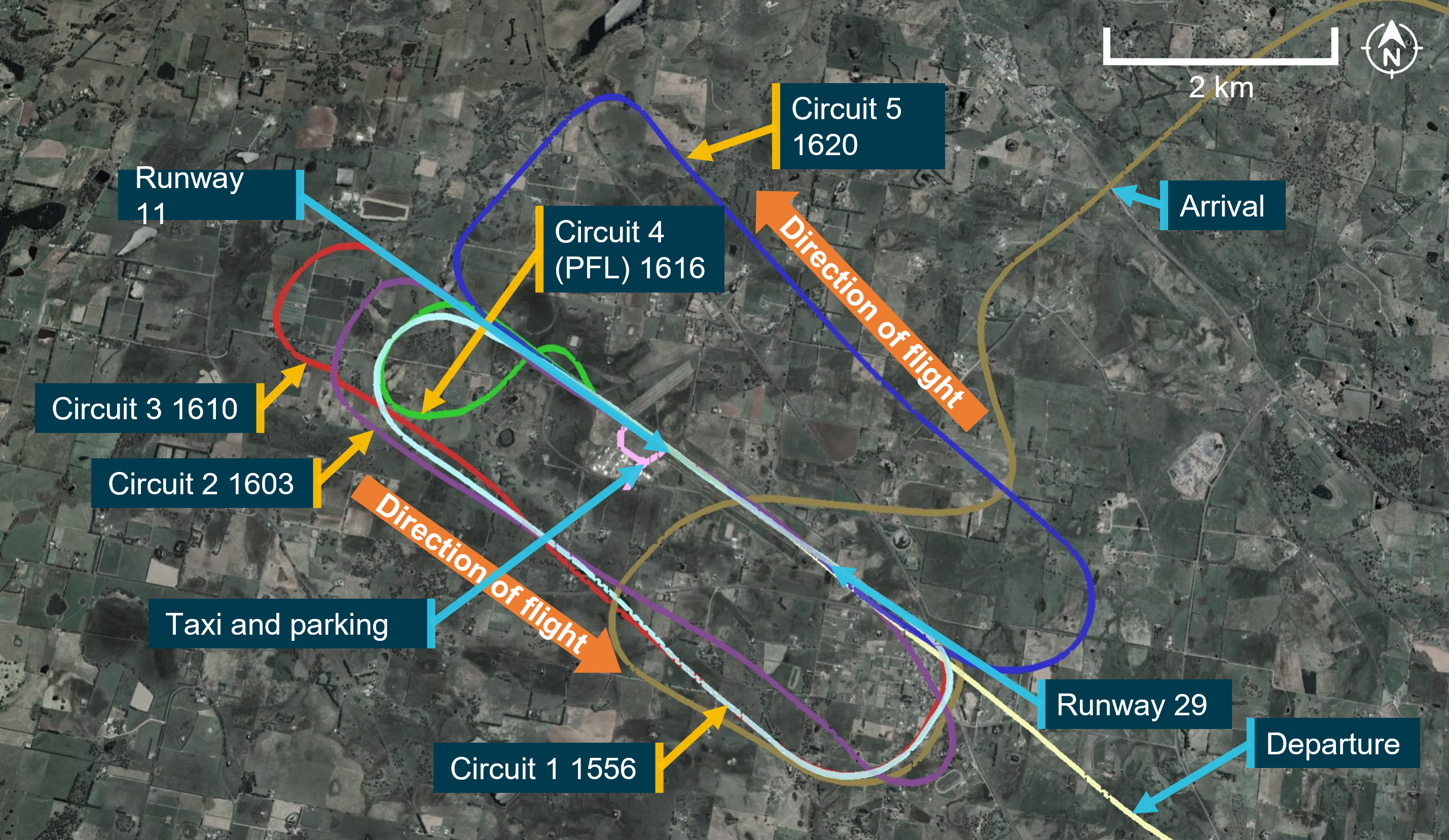
Figure 2: Flight path of VH-OIS at Orange Airport

Source: Google Earth, annotated by the ATSB

After a total of 8 minutes on the ground, OIS entered the main runway from the eastern taxiway and backtracked toward the runway 11 threshold. At 1637, the pilots broadcast that they were rolling on runway 11 and an upwind departure was conducted. Flight data indicated that during the initial climb from the runway, OIS maintained a nominal track on the extended runway centreline for about 9 km.

Audio recordings of transmissions from the Orange common traffic advisory frequency (CTAF) indicated that during this time, both pilots of OIS were in communication with an inbound passenger carrying flight. Once at about 9 km from the runway, the pilots of OIS broadcast on the CTAF that they were on a heading of 130° magnetic and levelling out at 5,000 ft AMSL, consistent with the flight data. OIS turned right briefly toward the township of Blayney and then left to proceed on a south-easterly track for about 2 minutes before turning right onto a south-westerly heading in the general direction of the township of Carcoar and Coombing Park aeroplane landing area (ALA).

Operations at Coombing Park

At 1653 a descent was commenced when OIS was abeam Coombing Park ALA, approximately 3 km to the north of the main east-west runway (runways 07 and 25) as shown in Figure 3. The pilots conducted 3 nominally rectangular patterns around Coombing Park runway 07.

At 1704, while on the easterly leg of the third pattern, the instructor of OIS made a phone call to the property manager of Coombing Park that lasted 24 seconds. The property manager recalled the instructor identifying themselves as an instructor from Soar Aviation and requesting permission to conduct a touch-and-go at Coombing Park. The property manager reported that they thought OIS was on the downwind leg for runway 25, and on this basis approved the touch‑and-go.

The pilots positioned OIS to land on runway 07, with flight data showing the aircraft on a descending profile on the base, and final approach circuit legs. The property manager described the final approach as stable and observed OIS descending to very near the ground at the runway 07 threshold. OIS was not visible to the property manager after this time due to their vantage point being slightly below the runway, however the manager, who was also a pilot, indicated that the projected touch-down point would have been very close to the runway 07 threshold based on the observed approach.

Flight data indicated that OIS passed over the runway 07 threshold at 1708, touched down and rolled along the runway surface. About 30 seconds after passing over the runway threshold, OIS become airborne again and commenced a climb, passing through 50 ft AGL approximately 900 m from the start of runway 07.

Figure 3: Flight path of OIS while operating at Coombing Park ALA
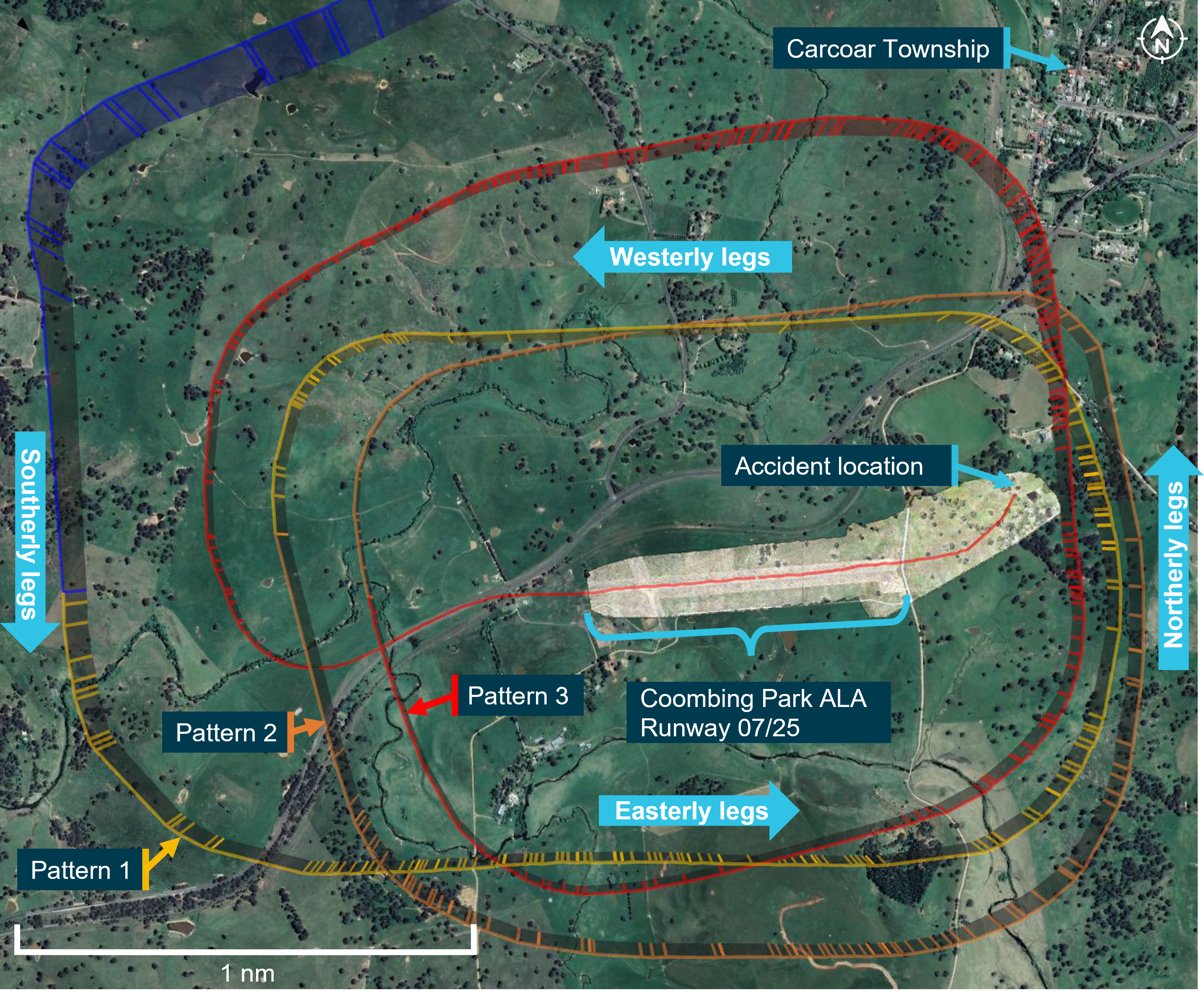
Figure 3: Flight path of OIS while operating at Coombing Park ALA

Source: Google Earth and Aireon, modified and annotated by the ATSB

During the initial climb, OIS tracked in a straight line angled slightly left of the runway centreline. Flight data indicated that, about 20 seconds later as OIS climbed through 200 ft above the lift-off point, a climbing left turn was conducted by the pilots before flying straight again in the direction of a small dam, beyond which was a less wooded area. OIS passed over the small dam and collided with an embankment on the far side of the dam. A witness heard the sound of the impact, although they did not realise it was an aircraft accident at the time, and there were no eyewitnesses to the accident.

At 1800, air traffic services commenced trying to contact the pilots of OIS via radio. At 1832, after being unsuccessful in contacting the pilots, an INCERFA[6] was declared with the search and rescue response being transferred to the Joint Rescue Coordination Centre. Local authorities were notified, and a search was commenced in the area. At 2157, the wreckage of OIS was located, and it was confirmed that both pilots had sustained fatal injuries.

Context

Pilot information

Flight instructor

Qualifications

The instructor held a valid commercial pilot licence (aeroplane) issued in March 2009, and a flight instructor rating issued in March 2010. The instructor also held a grade 1 training endorsement to instruct in single- and multi-engine fixed wing aeroplanes.

The instructor was also endorsed to conduct training for the issue of instrument and night VFR ratings. They passed a proficiency check for the flight instructor rating on 13 January 2020 that was valid at the time of the accident. Additionally, the instructor’s flight crew licence indicated that they had completed single- and multi-engine aeroplane flight reviews on 13 January 2020 and 28 July 2019 respectively that were also valid.

Experience

A review of the instructor’s logbooks, staff files and flight data showed that at the time of the accident they had accumulated a total flying experience of approximately 3,169 hours. About 16 of those hours were in the previous 30 days and about 56 hours were in the last 3 months. Most of the instructor’s flying experience was in single-engine aeroplanes (3,002 hours), with the instructor recording approximately 2,584 hours of total experience as a CASA‑qualified flight instructor. Staff records indicated that the instructor had accumulated 2,421 hours while working for the operator. The instructor had approximately 569 hours in the AT-01, the same type flown on the day of the accident, with about 33 hours in the last 3 months on that type.

Medical information

The instructor held a Class 1 aviation medical certificate that was valid until 12 June 2021 with no restrictions. The instructor was reported to be fit and active and in a good state of mind in the days before the flight and was likely well-rested. The instructor was not reported to be taking any prescription medications and had no reported medical condition that could have affected their ability to operate an aircraft that day. A post-mortem examination identified no significant background natural disease, which could have contributed to the accident.

Student

Qualifications

The student held a recreational pilot licence for single engine aeroplanes issued in December 2018, with a navigation rating for this licence issued in September 2019. The student also held recreational licence ratings for operations in controlled airspace, operations at controlled aerodromes and for the operation of flight radio. Additionally, the student was endorsed to operate aircraft with manual propeller pitch control. The student’s licence did not have an expiry date and was valid at the time of the flight.

Experience

A review of the student’s logbooks, student files and flight data showed that at the time of the accident the student had accumulated a total flying experience of approximately 259 hours. About 10 of those hours were in the previous 30 days and about 13 hours were in the last 3 months. Operator’s records indicated that the student had accumulated 174 hours while training with the operator, with the remaining 85 hours acquired previously at another flying school. The student had approximately 72 hours in the AT-01, the same type flown on the day of the accident, with all 13 hours flown in the last 3 months being on that type.

Medical information

The student also held a class 1 aviation medical certificate that was valid until 20 October 2021 with no restrictions. The student was reported to be well rested in the days before the flight. The student was not reported to be taking any prescription medications and had no reported medical condition that could have affected their ability to operate an aircraft that day. A post-mortem examination identified no significant background natural disease, which could have contributed to the accident.

Pilot fatigue information

Based on reported sleep data alone, it is unlikely that the crew were fatigued. It is possible that the student may have experienced some mental fatigue due to the assessment nature of the flight. However, there was insufficient evidence to make that determination. Further, the instructor was unlikely to be fatigued at the time of the accident.

Aircraft information

Overview

VH-OIS (OIS) (Figure 4) was an Aquila AT01 fixed-wing aircraft manufactured in 2012. The aircraft was first registered in Australia on 14 December 2012 to Soar Aviation Aircraft Holdings Pty Ltd (Soar). The aircraft was a two-seat, low‑wing training aircraft constructed from carbon fibre and fiberglass. Control surfaces were a mixture of push rod and cable operated. The power plant was a Rotax 912S with a two-blade constant speed propeller.

Figure 4: VH-OIS
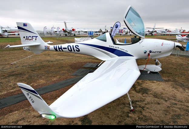
Figure 4: VH-OIS

Figure 4 shows VH-OIS on display at Avalon Airshow

Source: Andrei Bezmylov, used with permission

Maintenance

OIS had a current maintenance release located in the aircraft, issued on 1 September 2020 which was valid for a period of 150 hours or 12 months, whichever was sooner. At the time of the accident the aircraft had accrued 31.6 hours since the maintenance release issue and had a total time in service recorded as 3,540.9 flight hours.

The aircraft was maintained to the airframe and engine manufacturer’s inspection schedules with an operational category of aerial work. At the time of the accident, there were no listed defects or outstanding maintenance endorsed on the maintenance release.

Aircraft weight and balance

The aircraft had a valid load data sheet, with the empty weight and centre of gravity data approved on 30 October 2013. Weight and balance calculations performed by the ATSB found that OIS was below maximum take-off weight and within centre of gravity limits for the duration of the flight.

Flight data

The aircraft was not fitted with a flight data recorder or a cockpit voice recorder, nor was either required by regulations. Some Aquila models were fitted with a KAPI electronics flight data recorder, however, the manufacturer advised that this device was not fitted to OIS at the time of manufacture.

The primary source of flight data for OIS on the day of the accident was from satellite-based ADS‑B receivers operated by Aireon. These receivers are onboard the Iridium satellite constellation.

Aerodrome information

Coombing Park was classified as an ‘uncertified’ aerodrome, otherwise known as an aeroplane/aircraft landing area (ALA) and included one primary grass runway, and another shorter grass runway aligned about 70° from the primary runway (Figure 5). Coombing Park had an ICAO designator of YCPK, an elevation of 2,350 ft and had a common traffic advisory frequency (CTAF) of 119.0, shared with Orange Airport. The primary runway was nominally aligned in an east-west direction, at about 73° magnetic (85°T) (designated runway 07/25), and had a length of just over 1,200 m. The shorter runway was about 400 m long and aligned in a south-westerly and north-easterly direction and was reported as not being available for use.

The primary runway had a cleared area of more than 30 m on each side of the runway centreline that was free of obstacles. The runway at Coombing Park appeared in good condition at the time of the accident, with the surface being firm, the grass relatively short, and the conditions dry. The gradient of the runway matched the contours of the ground, rising in the direction of runway 07. Rising terrain existed to the east of the field, increasing to a local peak about 350 ft above the runway elevation about 1 km from the end of runway 07.

Two windsocks were present, one near the intersection of the 2 runways and the other near the end of runway 07 on the southern side, as shown in Figure 5. Both windsocks appeared complete, free to move, and in good condition. Powerlines were present about 200 m from the end of runway 25 crossing the extended centreline in a north-south direction less than a 5% gradient from the runway 25 threshold.

Figure 5: Coombing Park ALA facing north-east
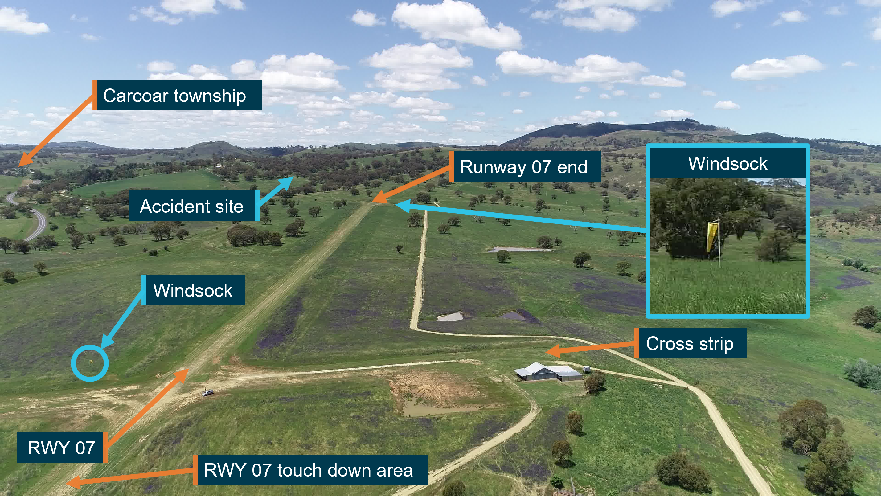
Figure 5: Coombing Park ALA facing north-east

Imaging showing a grass runway. Labels show location of the accident site, cross strip, touch down area of runway 07 and Carcoar township.

Source: ATSB

Information about Coombing Park ALA was available in the OzRunways application. This application was installed on the flight instructor’s mobile phone and was in use during the flight. At the time of the accident, the application had an additional ‘remarks’ section for Coombing Park that included:

Bird and animal hazard exist.


Rising terrain east of field.

No other procedures were included in this guide, nor were they required by any regulations. However, following the accident on 12 November 2020, additional information about Coombing Park ALA was included in the OzRunways application. The ‘remarks’ section was updated to include:

Rising terrain to East, crosswind departures from [runway] 07 only
 

Terrain at 3,953 within 3NM of field.

No go around on [runway] 07

Power lines at end of [runway] 25

Additionally, ‘procedures’ were added to the OzRunways application in the same update that included:


RH circuits on runway 07

Crosswind departures from [runway] 07

Up wind departures from [runway] 07 prohibited

Simulated engine failures prohibited

Engine failure on [runway] 07: make RH turn and glide to creek flat

Coombing Park ALA was not included in the Enroute Supplement Australia (ERSA).

Meteorological information

Weather information used by the pilots

Documents onboard the aircraft indicated that the student prepared a location briefing, including weather information, at 1304 using NAIPS. This briefing included a graphical area forecast (GAF)[7] for the planned area of operations, aerodrome forecasts (TAFs) and reported observations (METARs)[8]. TAFs and METARs were obtained for Bankstown and Young Airports, and METARs for Cowra Airport. Young Airport was located approximately 35 km from the originally‑planned waypoint near Greenethorpe Township. QNH[9] was also requested for the area of operations and was predicted to be 1014 for the duration of the flight.

The forecasts obtained by the student (TAFs and GAF) covered the duration of the planned flight. The TAF released at 1226 for Young Airport contained predictions for CAVOK[10] conditions. Surface winds were forecast at 12 kt from a westerly direction 290° (True), with the temperature ranging from 26‑28 °C. The GAF issued at 0924, and found onboard the aircraft, predicted visibility greater than 10 km and no significant cloud or weather phenomena for the duration and planned area of flight.

Post‑accident weather analysis

GAFs for the area of operations, TAFs and METARs for Bathurst and Orange Airports, and METARs for Cowra Airport were obtained from the Bureau of Meteorology (BoM) covering the duration of the flight. Although not requested by the student, the TAF released at 1234 for Orange Airport predicted similar operational conditions to Young. These were CAVOK, with similar surface winds at 10 kt also from a westerly direction (260° True), with a temperature of 22 °C. All forecast conditions evaluated predicted suitable weather conditions for flight under the visual flight rules.

Observed conditions at Orange Airport during circuits

The METAR for Orange Airport released at 1500, 4 minutes after OIS arrived, indicated similar conditions to those predicted by the TAF released at 1234. Visibility was greater than 10 km with no cloud detected, and surface winds were reported at 10 kt from a westerly direction (250° True), and a temperature of 24 °C and QNH 1016. Similar conditions were reported in the METAR released at 0530, 7 minutes prior to the departure of OIS from Orange. However, the wind direction changed to a south‑westerly direction (210° True) at 10 kt, with the temperature dropping to 23 °C and QNH 1015.

Estimated conditions on arrival at Coombing Park

Weather observations from Bathurst, Orange and Cowra Airports were used by the ATSB and the Bureau of Meteorology (BoM) to estimate conditions at Coombing Park ALA at the time of the accident (1709). These were the nearest aviation meteorological sites surrounding the ALA, with Cowra Airport being 50 km to the south-west, Orange Airport being 28 km north and Bathurst being 55 km to the north-east.

All METARs released at 1700 for these locations showed visibility greater than 10 km and no cloud detected, consistent with eye-witness reports from the time of the accident. QNH was recorded in METARs as 1011 at Cowra, 1015 at Orange, and 1014 at Bathurst, and was estimated as 1015 for Coombing Park, being closest to Orange. Temperature in the same METARs was 29 °C at Cowra, 23 °C at Orange and 25 °C at Bathurst, and was estimated as 24 °C at Coombing Park, based on the aerodrome elevation and proximity to Orange.

Surface wind analysis

The BoM conducted an analysis of surface winds at the accident site based on the surface winds reported in 1-minute intervals at Cowra, Orange, and Bathurst. BoM estimated a surface wind direction of westerly though north-westerly, with an estimated wind speed of 5‑10 kt, possibly up to 15 kt. Surface wind gusts were not expected to exceed 5‑15 kt, although gusts up to 20 kt were possible, consistent with observed wind gusts at Cowra, Orange and Bathurst. Based on this analysis, if the wind was north-westerly, the mean tailwind component on runway 07 was estimated between 3‑6 kt, gusting up to 13 kt.

If the wind was from a westerly direction, the mean tailwind component was estimated between 5‑10 kt and gusting up to 20 kt. The crosswind component would have likely ranged between 2‑8 kt from the left of OIS, and possible crosswind gusts up to 15 kt. Based on the runway direction, BoM reported that it was unlikely that there was a headwind component to the surface wind over the runway at the time of the accident.

Estimation of tailwind

The ATSB also estimated the tailwind component on runway 07, based on the groundspeed of OIS during approach to land. Flight data indicated that the ground speed on late final approach of OIS was about 67 kt. Based on a recommended approach indicated airspeed of 60 kt, as required by the AFM for OIS, the nil wind ground speed or true airspeed at the elevation of Coombing Park for this indicated airspeed was calculated as 62.3 kt. Based on this, the mean tailwind component was estimated to be 5 kt, within the bounds of the probable wind speed provided by the BoM.

Aircraft performance information

Touch-and-go information

Data for the accident flight showed that, following the 2 left precautionary search patterns around Coombing Park ALA, the aircraft flew parallel to the main runway (corresponding to the left downwind leg for runway 07) before a left descending turn was conducted (base leg). At the completion of this turn the aircraft was slightly right of the runway 07 centreline, approximately 1,200 m horizontally from, and 300 ft above, the runway threshold. The approach flight path indicated that a slight left tracking correction was likely performed to align the aircraft with runway 07. An eye-witness, who was a pilot familiar with the strip and situated approximately 300 m to the west of the runway 07 threshold reported that the aircraft flew about 40 ft above the trees in a very flat, low and slow approach.

The eye-witness also reported that the approach appeared to be smooth, well configured and balanced, to have lots of flap out, with the engine sounding normal. At the time the aircraft flew past, the runway was not visible to the eye-witness due to the vantage point being slightly below the runway threshold. However, the eye-witness recalled stating to a friend that they hoped the aircraft didn’t land short of the strip when observing the approach. The eye-witness expected that the aircraft would have touched down ‘right near’ the runway 07 threshold, based on the flight path and slow airspeed observed. There were no witness marks identified by the ATSB on the runway surface that were indicative of a hard or abnormal landing. The touch down area for runway 07 (Figure 5) was slightly less grassed than other parts of the runway, consistent with normal landings in that area, no marks were found that could be attributed to the touch-and-go.

ATSB evaluation of flight data along the runway strip showed that the previously‑observed descent rate during the approach was no longer discernible shortly after the aircraft crossed the runway 07 threshold. However, it was not possible to identify the exact position of touch down due to the precision of this data. This data also indicated that the aircraft crossed the runway threshold at a ground speed of approximately 60 kt, with the aircraft beginning to reduce speed about 5 seconds after this point. Within about 10 seconds, the groundspeed reduced to a minimum speed of about 44 kt approximately 400 m past the runway threshold. The flight data then indicated that OIS began to accelerate, consistent with application of engine power by the pilots. ATSB evaluation of flight data estimated that lift-off and climb to 50 ft likely occurred approximately 929 m from the runway 07 threshold, attaining a stable ground speed of about 63 kt during the initial climb.

Evaluation of touch‑and‑go length

The ATSB performed a comparative analysis between the length (distance from the runway threshold to the take‑off point) of the touch-and-go at Coombing Park compared to the length of 4 touch-and-go landings and the standing take-off conducted at Orange Airport. The purpose of the analysis was to identify any factors that may have increased the length of the touch-and-go at the ALA. Further detail on this analysis, including methodology, additional context and findings of this analysis are described in Appendix A – The influence of touch‑and‑goes to the accident involving VH-OIS, 4 November 2020. A summary of the findings from this analysis are as follows.

The length of the Coombing Park ALA touch-and-go was the third shortest of the flight. The two shortest touch‑and‑go landings conducted at Orange at 1602 and 1615 had lengths of just over 750 m. The fourth shortest touch‑and‑go was conducted at Orange at 1556 (the first approach) and had a length of about 1,000 m.

The ATSB applied corrections for aircraft mass, density altitude and surface type to estimate the length of the Coombing Park touch‑and‑go if it had been conducted at Orange (the corrected touch‑and‑go). The purpose of this correction was to allow a direct comparison between the Coombing Park touch-and-go and all take-offs conducted at Orange. The corrected touch‑and‑go was estimated to have a length between 812 m (with a 25% factor applied for dry grass) and 1,015 m (no grass strip correction) (as stated above the actual length was 929 m). Based on these estimations, it is likely that if the Coombing Park touch‑and‑go had been conducted in the same way at Orange Airport, the length would have been in the same ranked order (that is, third shortest).

The ATSB also evaluated the potential effect of OIS performing a standing take-off instead of the touch‑and‑go at Coombing Park under the same conditions, and this is also detailed in Appendix A.

From this analysis, the standing take-off length at Coombing Park was estimated to be between 630 and 836 m. The estimated zone along Coombing Park runway 07 where OIS would have climbed to 50 ft from a standing take-off is shown in pink in Figure 6. This figure also shows the location of the start of runway 07, the actual take-off for OIS, the upwind track in red-dashed lines, and an indicative track for the start of the left turn. The reference tree is shown for continuity between figures in this report.

Figure 6: Upwind track of OIS following touch‑and‑go at Coombing Park ALA, (view looking south-west)
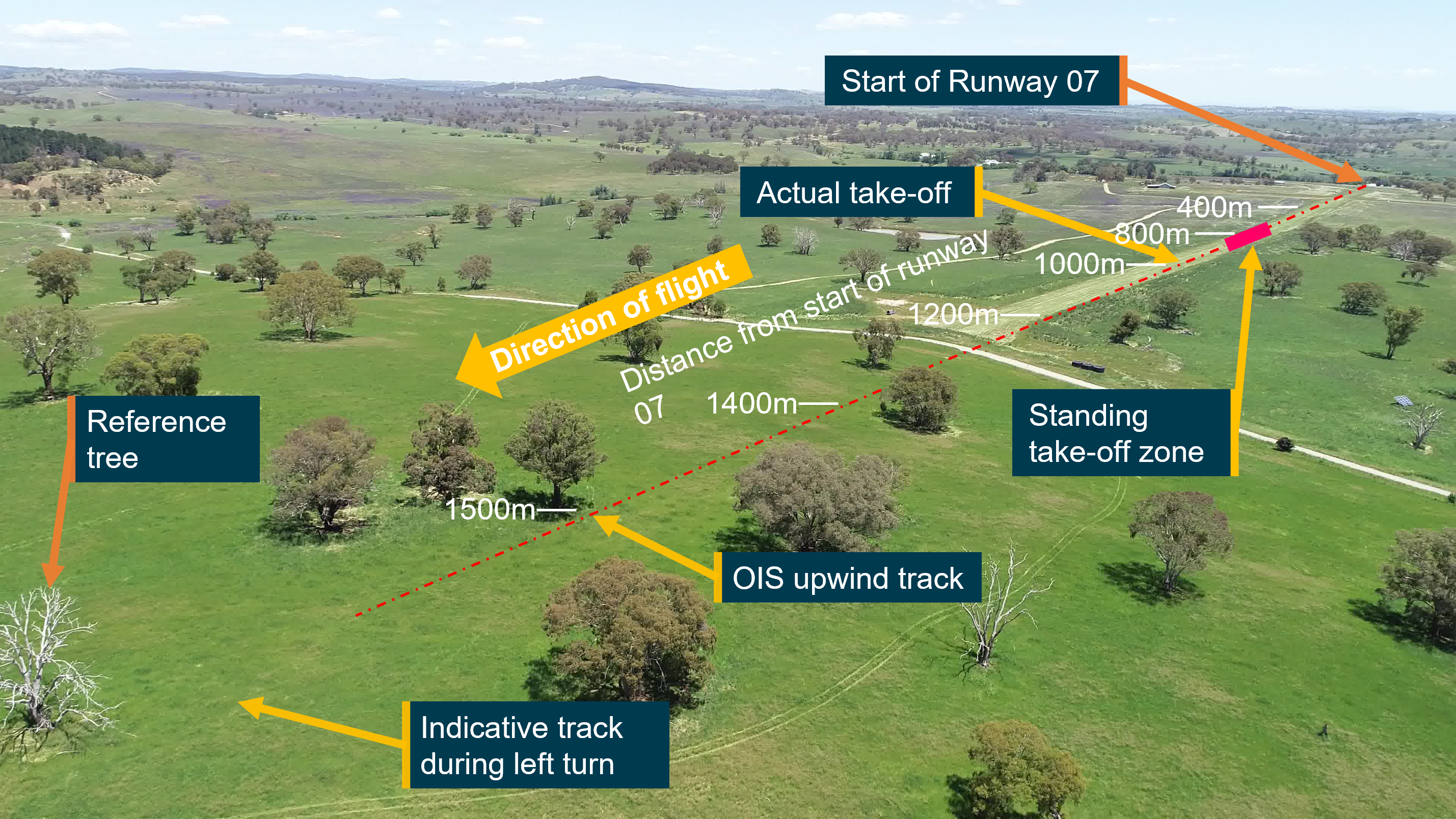
Figure 6: Upwind track of OIS following touch‑and‑go at Coombing Park ALA, (view looking south-west)

Image showing upwind track of OIS (red dashed lines), actual take-off position of OIS and estimated take-off zone if a standing take-off was conducted

Source: ATSB

Guidance for determining touch‑and‑go length

There were no details for the calculation of touch‑and‑go length in the aircraft flight manual (AFM), nor were these required. Research by the ATSB identified a limited number of guidance publications for the calculation of a suitable runway length for a touch‑and‑go. Two articles were identified that presented anecdotal techniques for the calculation of required runway length for a touch‑and‑go. As context to the challenges associated with a touch‑and‑go in an article by Aviation Safety magazine, Burnside (2019) stated:

The principal challenge posed by the touch‑and‑go manoeuvre is managing the immediate transition from a landing to a take-off, presenting that touch‑and‑goes are more complicated than just stringing together a landing with a take-off.

Further, in an article released by the Aircraft Owners and Pilots Association (AOPA), Wright (2006) identified some of the challenges that may be encountered by a pilot during a touch‑and‑go after the aircraft has landed:

Once power is added, the pilot is now concerned with achieving a normal take-off rotation speed while ensuring that there is sufficient runway to safely clear any obstacles. Somewhere in all of this there must be a verification that the flaps really did retract, the engine instruments are giving normal readings, and all required checklist items are accomplished.

At some undefined point, the landing roll ends, and the take-off roll begins. If the runway is relatively short, it may leave you with little to no room to execute a safe rejected take-off. Likewise, floating too long during the landing or being slow in retracting flaps may bring on the same situation.

The articles by Wright (2006) and Burnside (2019) each presented a method to estimate a safe length for a touch‑and‑go to be conducted. Wright (2006) stated:

A good rule of thumb is to take the landing distance over a 50-foot obstacle and the take-off distance over a 50-foot obstacle, add them, and double (or triple) the result to get a minimum runway length.

Burnside (2019) provided a sample calculation based on 3 elements. In summary, this sample calculation involved calculating:

  • The average of the landing roll and landing distance required to clear a 50-foot obstacle;
  • the time on the ground to reconfigure the aircraft, and;
  • the average of the take-off ground roll and take-off distance required.

In this article, Burnside (2019) identified several reasons to be more conservative than this, citing that pilot technique, a less than perfect engine, a dragging brake or a crosswind requiring drag-producing aileron input can change those numbers.

Significantly, both methods estimated that a touch-and-go length used more runway than a standing take‑off. Additionally, the analysis conducted by the ATSB also identified that all touch-and-go manoeuvres conducted by the student were likely to use more runway than a standing take-off.

Specifically, when corrected for density altitude, a standing take-off length at Coombing Park ALA was estimated by the ATSB to be between 630‑836 m for the atmospheric and weather conditions at the time of the accident, notably shorter than the actual Coombing Park ALA touch‑and‑go length of 929 m.

Initial climb performance

The ATSB evaluated the potential influence of a standing take-off on the height of OIS during the initial climb. The analysis indicated the relative height difference if a standing take-off was conducted instead of the actual touch-and-go. The climb profiles are projected in straight lines, along an extended upwind track, although these results also indicated the relative differences between a standing take-off and the touch-and-go on curved flight paths. The distance from the start of Coombing Park ALA runway 07 was used as the datum for the analysis, and this is shown on the horizontal axis of Figure 7. For reference, these distance markers are reproduced over an image of the runway area in Figure 6 and the upwind area in Figure 9.

This analysis used the estimated standing take-off distances described in the section above and is illustrated in Figure 7. The vertical axis shows the height above the estimated point of lift off and the horizontal axis shows the distance from the start of runway 07 at Coombing Park ALA, and also corresponds to the markers shown in Figure 6.

Terrain elevation is shown by the solid dark green area, with typical tree heights indicated by the translucent dark green (minimum 33 ft (10 m)) and light green (maximum 66 ft (20 m)) areas.

Figure 7: Height of initial climb profile for OIS at Coombing Park ALA, including estimations for climb profiles following standing take-off and estimated terrain profile
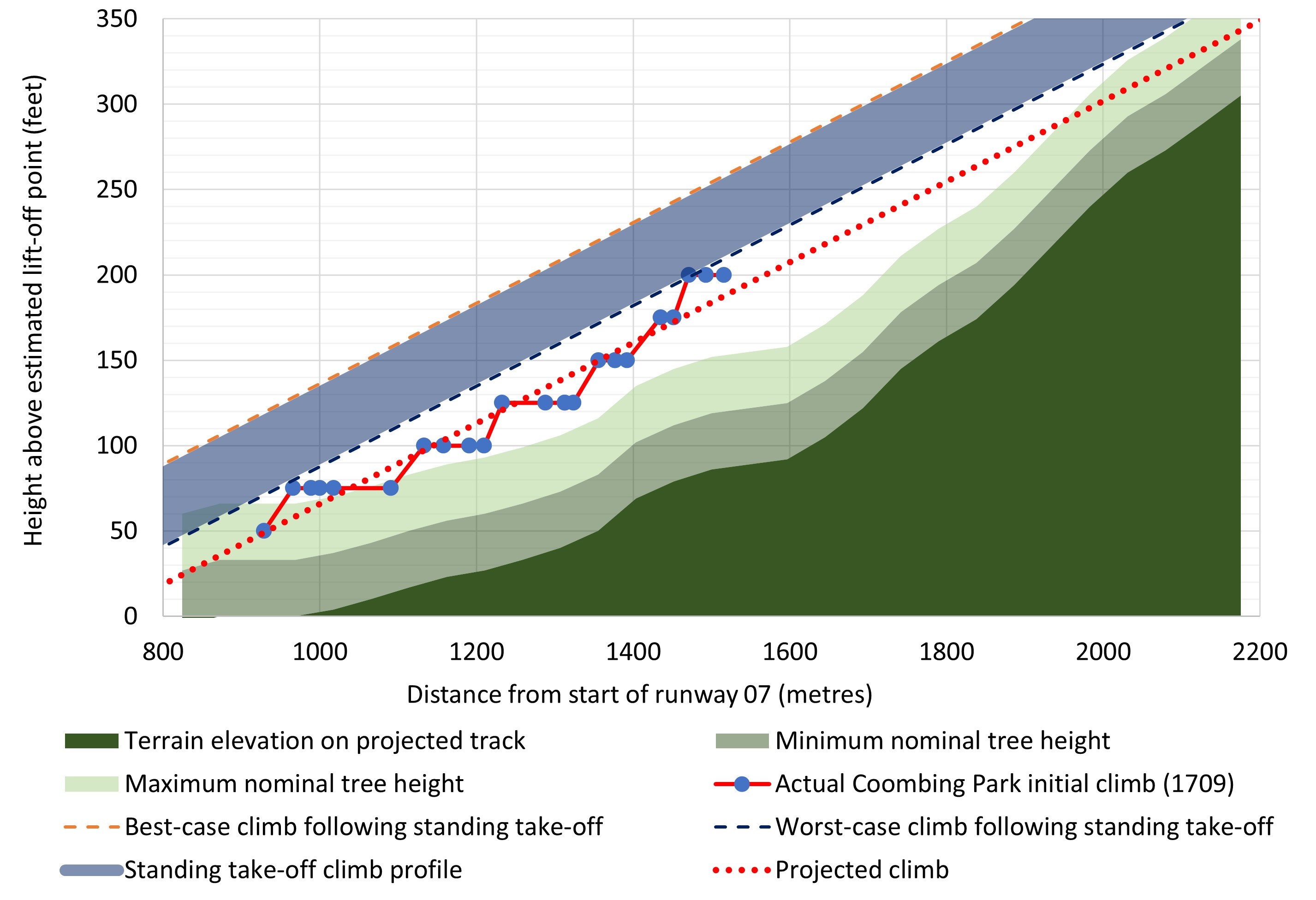
Figure 7: Height of initial climb profile for OIS at Coombing Park ALA, including estimations for climb profiles following standing take-off and estimated terrain profile

Figure showing plot of height vs distance travelled of OIS during the initial climb from Coombing Park ALA runway 07 compared to terrain and estimates for climb if a standing take-off was conducted.

Source: ATSB

The actual initial climb profile of OIS conducted at 1709 is shown in Figure 7 by the series with red lines and blue circles. The last data point of this series indicates the relative height of OIS immediately prior to the left turn. The red dotted series is the line of best fit for the 1709 initial climb and shows an estimated projection of the climb if the climb rate was maintained and OIS tracked in a straight line instead of turning left. The top right corner of Figure 7 shows the projected climb passing within about 45 ft (14 m) of the terrain, below the maximum nominal height.

The likely climb profiles following theoretical standing take-offs at Coombing Park ALA are shown by the blue band (labelled ‘Standing take-off climb profile’ in Figure 7). The standing take-off climb estimates show the result of translating the actual climb of OIS at 1709 to start from take-off locations of theoretical standing take-offs at Coombing Park ALA, as described in the section ‘Estimation of standing take-off distances’ in Appendix A.

The dashed lines above and below the blue band represent the limits of the analysis, with the best-case shown in orange and the worst-case shown in dark blue. The best-case scenario is derived from the shortest theoretical standing take-off (630 m), and the worst-case is derived from the longest theoretical standing take-off (836 m), as described above. The top right corner of Figure 7 shows all climbs following hypothetical standing take-offs as passing close to, but above the maximum nominal tree height at the local terrain peak, with the worst case projected to pass within about 67 ft of the terrain.

The best- and worst-case standing take-off estimates equated to OIS being between 22‑70 ft higher at each point during the initial climb if a standing take-off was conducted instead of a touch‑and-go, as shown by the height differences between these lines and the dotted red-line in Figure 7. In contrast to the initial climb after the actual touch-and-go projecting below the maximum tree height, climb projections from standing take-off estimates indicated that OIS would pass close to, but slightly above the maximum nominal tree height had an upwind departure been conducted. Further climb performance analysis for curved flight paths are discussed in the section titled Turn and final track information below.

Initial climb gradient

At the time of the accident, flight planning legislation required pilots to plan to take-off with the aircraft weight sufficiently low to allow the aircraft to achieve a minimum climb gradient. This was stipulated in paragraph 7.1 of Civil Aviation Order 20.7.4, which stated:

In the take-off configuration with landing gear extended, an aeroplane must have the ability to achieve a climb gradient of 6% at take-off safety speed, without ground effect, and with all engines operating at take-off power.

Based on flight data, the ATSB calculated the climb gradient of OIS during the initial climb from Coombing Park to be just over 7%. This was based on the flight data for OIS between 50 ft and 200 ft above the lift-off point (shown by the red line with blue circles in Figure 7). OIS was very likely outside ground effect for this segment of the flight. Further, the climb gradient of OIS was typical of climbs performed earlier in the flight at Orange.

Initial climb rate

The ATSB evaluated the climb rate of OIS after take-off from Coombing Park compared to climbs after take-offs at Orange Airport, earlier in the flight. Climbs after take-off were evaluated from 50 ft above the surface, to reduce uncertainty associated with the transition from the ground roll to a stable climb, including ground effect. Corrections for density altitude were performed on the climbs at Orange (increasing the actual values by 3.6%) to compare with the Coombing Park initial climb which had a lower elevation. Figure 8 shows the results of this comparison.

Figure 8: Climb rate of OIS after take-off at Coombing Park ALA, and climb rate for OIS at Orange Airport corrected for density altitude at Coombing Park ALA, 4 November 2020
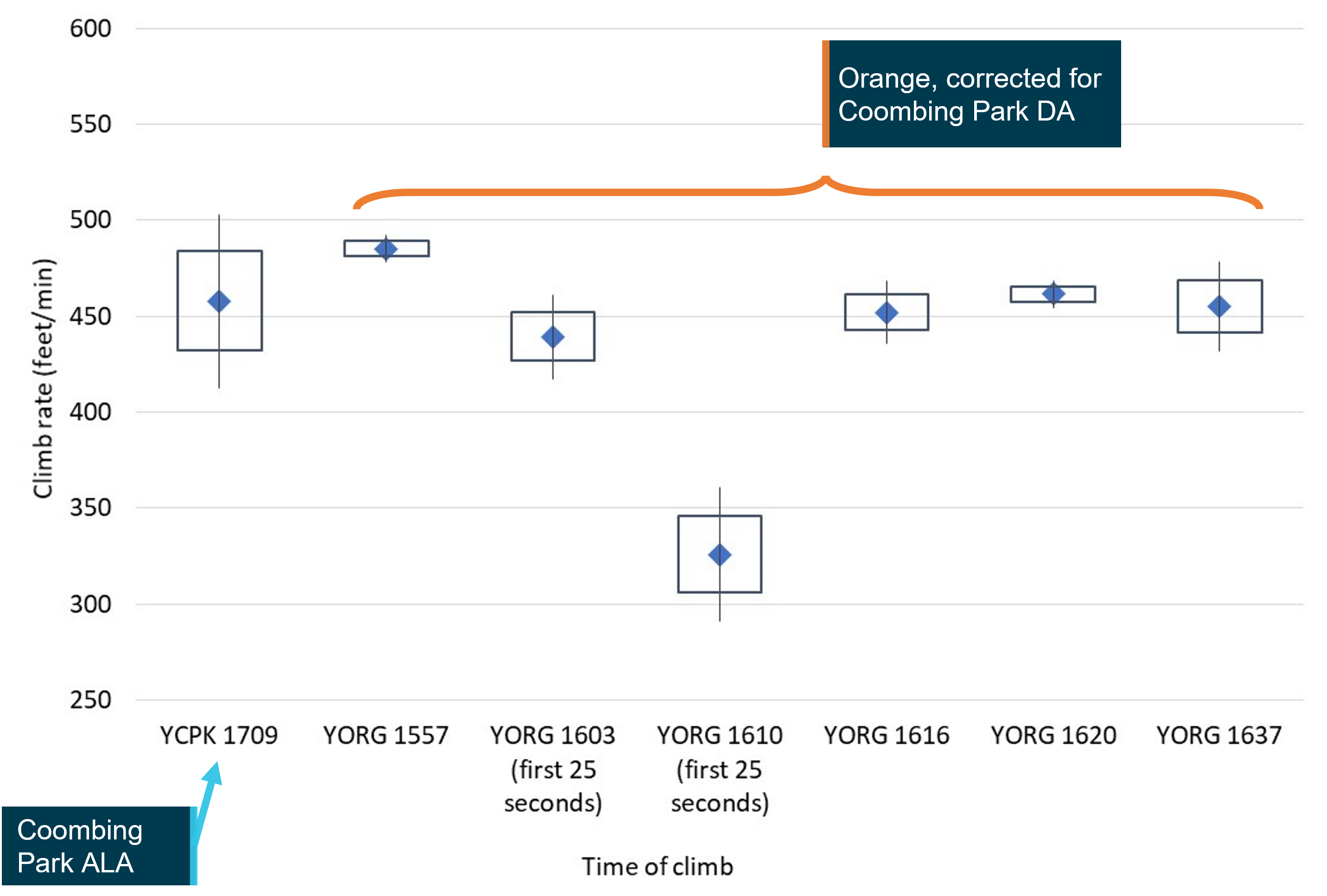
Figure 8: Climb rate of OIS after take-off at Coombing Park ALA, and climb rate for OIS at Orange Airport corrected for density altitude at Coombing Park ALA, 4 November 2020

Chart showing comparisons between initial climbs conducted at different times during the flight

Source: ATSB

The blue diamonds in Figure 8 show the mean climb rate calculated for each climb away from the runway, indicated in ft per minute by the vertical axis, with labels on the horizontal axis indicating the local time that each climb was commenced. The height of the boxes and vertical lines around the mean illustrate uncertainty in the rate of climb, with the boxes indicating where the mean climb rate likely existed, and vertical lines (whiskers) indicating where the mean climb rate very likely existed.[11], [12], [13]

The left most data point labelled ‘YCPK 1709’ shows a mean climb rate of about 460 ft per minute during the straight component of the initial climb from Coombing Park runway 07. This rate was comparable to the initial climbs conducted in OIS at Orange at 1603, 1616, 1620 and 1637. The considerably lower initial climb rate at 1610 is consistent with an aborted landing being conducted with full flaps extended, a planned exercise as part of the CPL assessment.

Based on the AFM for OIS applied to the observed conditions at Coombing Park ALA, the best rate of climb was 580 ft per minute. The best rate of climb in the AFM is calculated based on test flights conducted under normal operating conditions, typically using a new aircraft and engine, with the aircraft flown in an optimal configuration. For this reason, it is not expected that OIS would have achieved the published climb rate in the AFM. Due to the damage to OIS, it was not possible to perform further assessments to establish why the rate of climb differed between OIS and the expected rate of climb in the AFM. However, it should be noted that the examination of the wreckage by the ATSB did not reveal any mechanical faults or defects with OIS, as described in the section titled Wreckage and accident site information.

In summary, flight data analysis conducted by the ATSB identified that the climb performance of OIS during the initial climb at Coombing Park ALA was comparable to climbs conducted at Orange Airport earlier in the flight.

Turn and final track information

Flight data indicated that immediately prior to turning left, OIS was approximately 125 ft above the ground (Figure 7), tracking toward steeper terrain with a significant number of trees. Figure 9 shows an image facing in a similar direction and at a similar height to the pilots just prior to where the left turn was initiated. The projected upwind track with distance markers shows the rising terrain corresponding to the elevation profile shown in Figure 7, with the same reference tree as shown in Figure 6. The projected upwind track provides a relative guide for analysis of climb performance covered in other section and does not necessarily indicate the intended track of OIS.

Figure 9: Image looking uphill at a similar height and position to OIS immediately prior to left turn
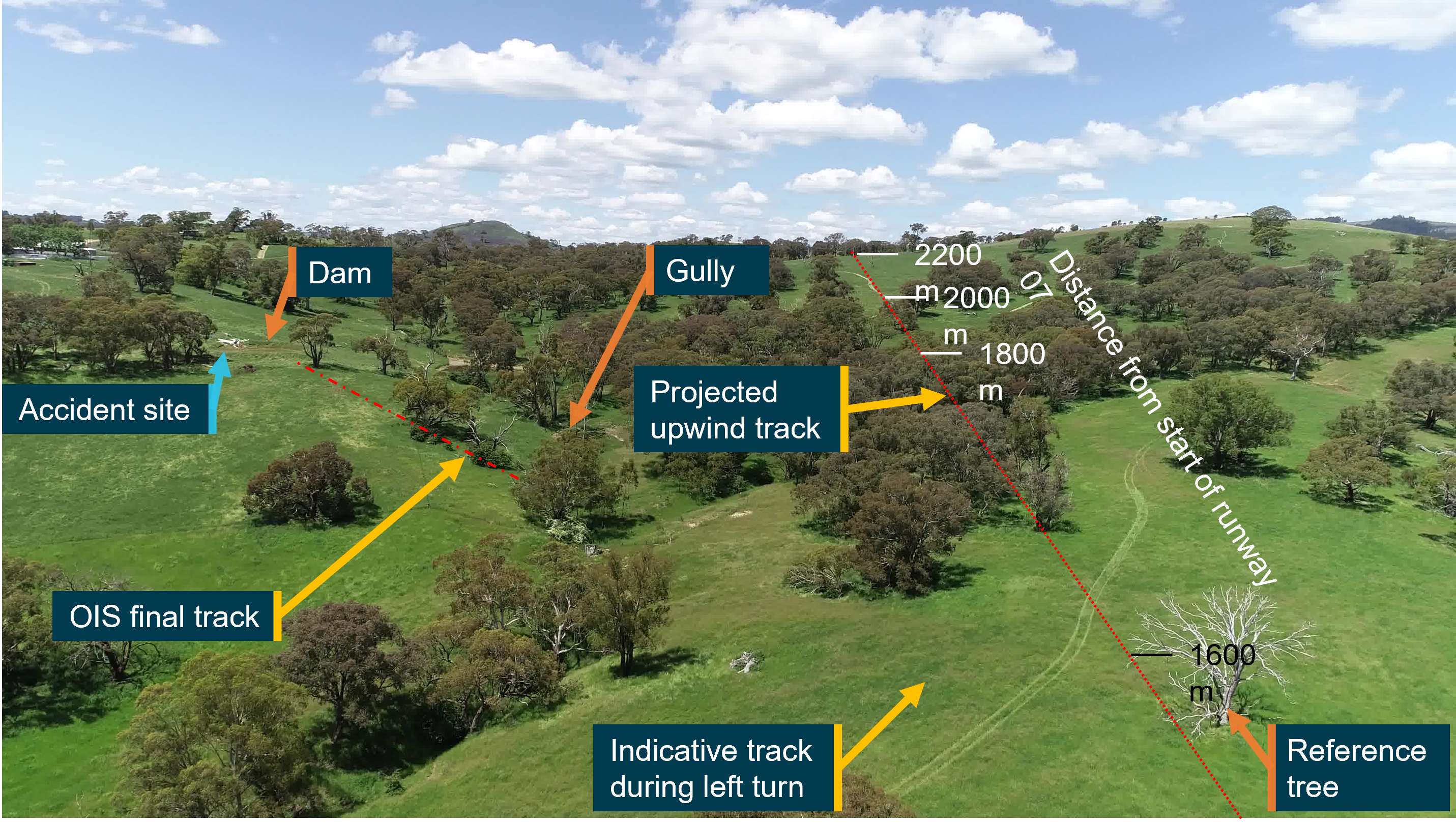
Figure 9: Image looking uphill at a similar height and position to OIS immediately prior to left turn

Image showing upwind track of OIS, approximate track during left turn and projected track if OIS continued in a straight line

Source: ATSB

Figure 10 shows a top-down image of the upwind area of runway 07 for Coombing Park ALA. This shows the entire track of OIS in red lines with blue circles, including the initial upwind track for the climb profile in shown in Figure 7. For reference, common labels such as the distance markers and reference tree are included in Figure 6, Figure 7 and Figure 9.

Figure 10: Image looking down on upwind area of Coombing Park runway 07 showing track of OIS and accident site
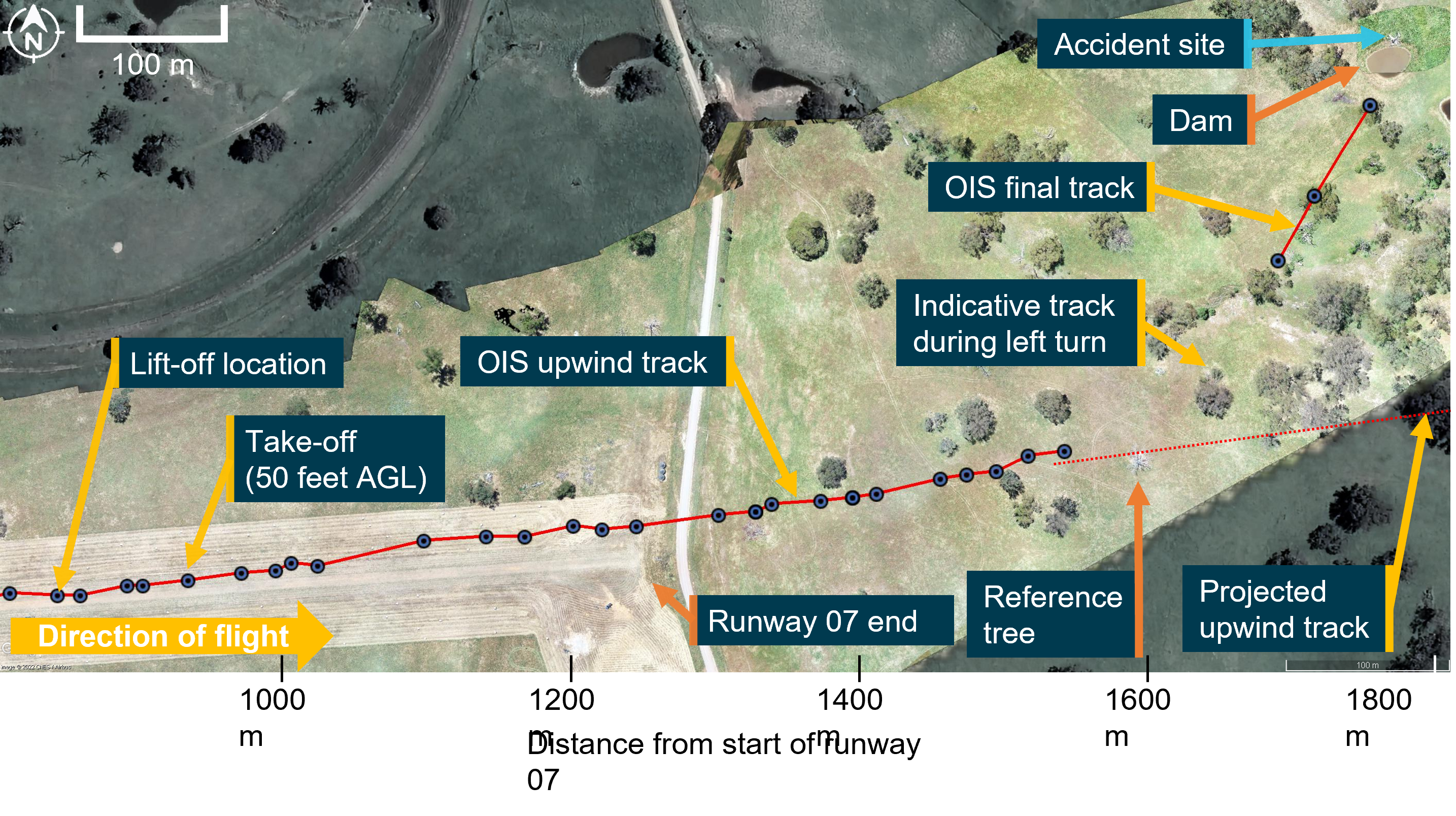
Figure 10: Image looking down on upwind area of Coombing Park runway 07 showing track of OIS and accident site

Down-looking image of runway 07 end of Coombing Park ALA and flight track of OIS

Source: Google Earth, with image overlay and annotations by ATSB

An indicative track of the left turn and final track of OIS is also shown in Figure 10. Flight data indicated that as OIS approached a line of trees, the track changed by about 50° to the left in less than 7 seconds, corresponding to a turn rate of more than 450° per minute. The radius of the turn was estimated to be about 185 m, with an angle of bank calculated as 22°.

Compared to other climbing turns conducted during the flight, the turn rate was almost twice as high, and the bank angle was at least 60% steeper. During the turn, OIS continued to climb, although at a reduced rate, gaining about 25 ft by the completion of the turn, with the mean groundspeed decreasing slightly.

The ATSB conducted a climb performance analysis to evaluate 3 hypothetical ‘escape’ scenarios for OIS:

  • continuing the left turn,
  • turning right instead of turning left, or
  • ceasing the left turn half-way through and flying straight up the gully (shown in Figure 9).

This involved projecting a climb profile over the terrain elevation map based on Google Earth and the estimated height of surrounding trees. Based on this evaluation, the hypothetical flight profiles for the left and right turns both passed within about 66 ft (20 m) of the ground. This was a similar height to the trees in the area.

The flight up the gully was estimated to pass within about 72 ft (22 m) of the ground. Although this was marginally higher than the trees in the area, due to uncertainty in the data, it was not possible to determine if OIS would have been able to climb away in this scenario.

Flight data and onsite measurements indicated that following the left turn, the height of OIS is likely to have been similar to the canopy height of surrounding trees for the third- and second-last data points, although the precise height could not be determined. Beyond the tree close to the flight path (shown in Figure 11), projections indicated that if the climb rate was restored after the turn and OIS had cleared this tree, the aircraft would have passed within 66 ft (20 m) of the ground in the rising terrain beyond the dam at a similar height to trees in the area.

The last 3 flight data points indicated that the ground speed of OIS likely increased, with OIS travelling approximately 110 metres in 3.2 seconds between these 3 points. OIS likely descended by at least 25 ft, possibly by 50 ft between the last 2 flight data points. This was likely to the left of and below the canopy of the tree close to the flight path. Approximately 1 second after the last flight data point, OIS collided with the embankment on the far side of the dam at a similar height.

Wreckage and accident site information

Accident site

The accident site was located on private property about 38 km south of Orange township and 27 km south of Orange Airport (Figure 1). This property was adjacent to Coombing Park ALA, with OIS located about 600 m from the end of runway 07, and about 300 m left of the extended runway centreline (Figure 3).

Wreckage examination

Site and wreckage examination did not identify any aircraft defects or anomalies that might have contributed to the accident. Examination of the area surrounding the accident site, including the tree close to the likely flight path (labelled), did not identify any trees or terrain that might have been struck by OIS prior to the wreckage location (Figure 11).

Figure 11: Image looking down on accident site and surrounding trees viewed from the direction of travel
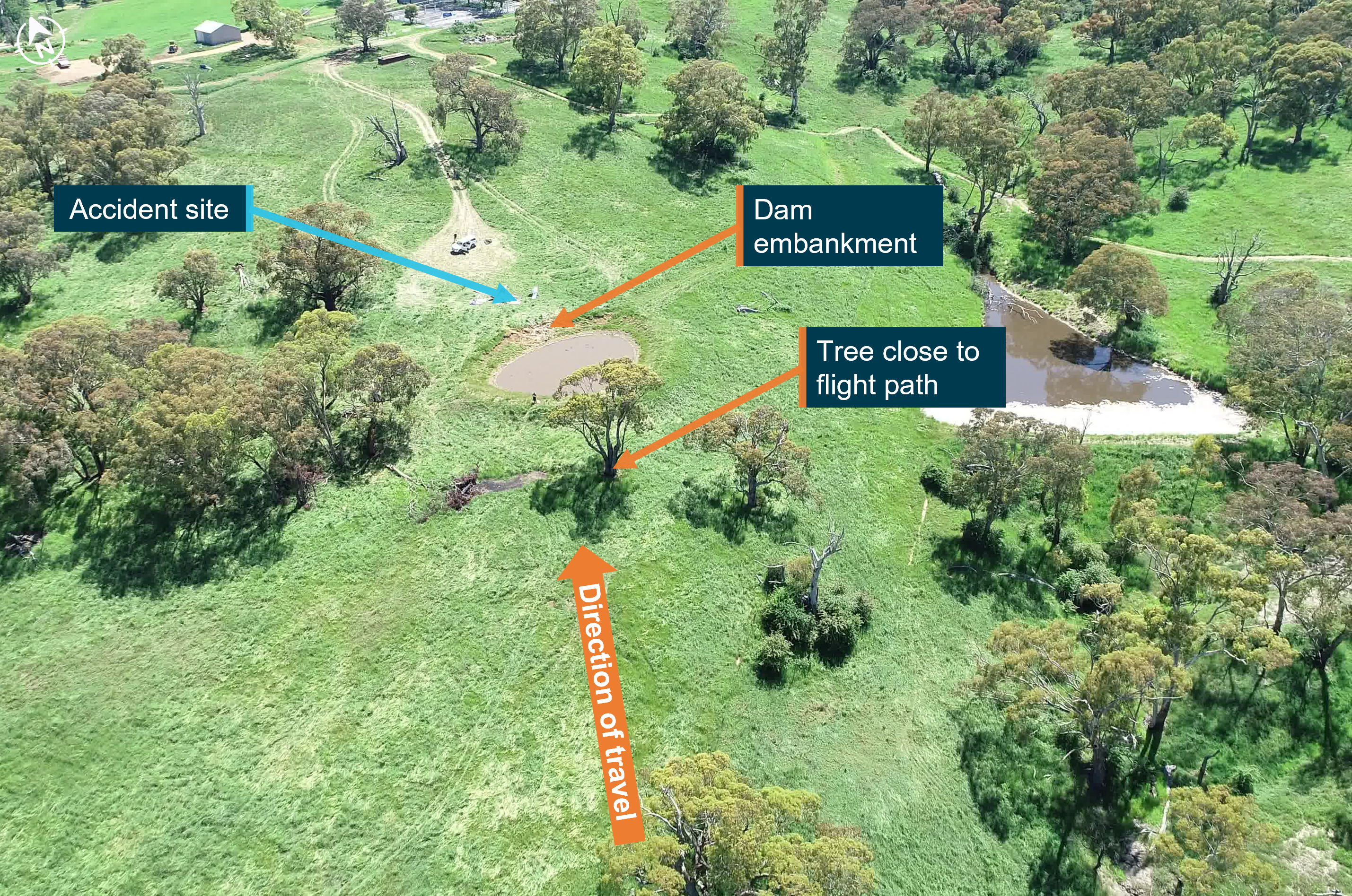
Figure 11: Image looking down on accident site and surrounding trees viewed from the direction of travel

Image showing accident site and surrounding trees

Source: ATSB

The aircraft struck the embankment of a small dam in an upright attitude. Flight data and ground scars marks indicated that OIS was tracking in a generally northerly direction at the time of the collision with terrain. The accident site was located slightly to the left of the projected track, with propeller strike marks indicating that the nose of the aircraft was pointed to the left of this track around the time of the collision. During the collision, the aircraft rotated in a counter-clockwise direction, coming to rest facing toward the south-south‑west, about 180° to the direction of travel.

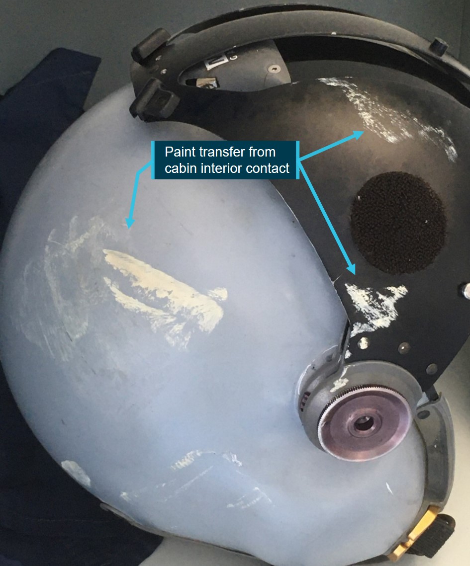
The damage to OIS was consistent with significant upward and rearward forces being transferred through the aircraft structure during the collision. The left wing and left-wing flight controls, aircraft canopy, cockpit area, nose landing gear, engine cowling, propeller and tail section of the aircraft were severely disrupted by impact forces. The counterclockwise rotation during the collision was likely induced by the left side of the aircraft (mostly from the left wing that was completely destroyed) colliding with the dam embankment prior to the right side of the aircraft.

Engine and propeller

The engine assembly was examined and found to be complete with no evidence of pre-accident engine control problems or defects. The inspection found all engine controls were connected from the cockpit controls through to the engine, with all electrical wiring and hoses connected.

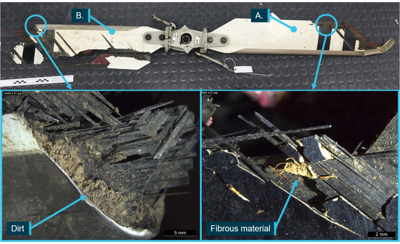
Both propeller blades fractured and separated from the propeller hub during the collision. Both tips of the propeller blades were located at the accident site. No evidence of pre-accident damage was identified in the propeller blades, propeller hub or propeller hub attachment to the engine crankshaft. The propellers broke into multiple fragments, and most fragments were located at the accident site. However, one large portion of blade was located about 27 m to the east of the site, consistent with this portion breaking away and being thrown through the air during the impact sequence.

Fuel

OIS was fully fuelled immediately prior to departure from Bankstown Airport and had sufficient fuel to conduct the flight. An onsite inspection identified that both the left- and right-wing fuel tanks were compromised with no fuel being identified in these tanks. Fuel was identified in both carburettor bowls and was found to be clear of contaminants, including water.

Emergency locator transmitter

OIS was fitted with an emergency locator transmitter that activated automatically during the accident sequence. This was deactivated by the ATSB onsite. The signal from the ELT was not received by emergency services, likely due to damage sustained to the antenna during the accident.

Flight controls

Flight controls were examined to the extent permitted by impact damage. Nothing was identified in the wreckage with respect to a flight control defect or malfunction that may have contributed to the accident. Complete continuity of flight controls from the cockpit to the control surface was established for the right-wing aileron, flaps, elevator, rudder, and elevator trim. The elevator trim position was unable to be established.

Continuity of the left-wing aileron and flaps was partially established from the cockpit to the control surface attachment brackets. Push rods and bell cranks associated with the wing mounts of these control surfaces were detached from the left wing during the collision, however, no pre‑existing defects were identified in these components.

The flaps were separated from the flap control actuator during the collision. The flap control actuator included a screw jack with the function of moving and holding the flaps in a fixed position. The extension of the screw jack had a corresponding flap position in the normally functioning aircraft. The ATSB was advised by the aircraft manufacturer that the measurement on the screw jack extension corresponded with the flaps being fully retracted.

Precautionary search information

A precautionary search and landing is a procedure for conducting a safe, powered landing away from an airport or ALA with known suitable landing surface conditions. It is normally conducted for two reasons:

  • A landing on an unprepared landing surface made necessary due to an abnormal or emergency situation, such as deteriorating weather, insufficient remaining daylight, fuel shortage, technical problems, developing medical conditions or any other reason determined by a pilot
  • A pre-planned landing when the pilot is unfamiliar with the landing area, or its condition is unknown.

Soar operations manual

Procedures at Soar were governed by an operations manual, as required by Civil Aviation Safety Regulation Part 141, regulation 141.260. This manual was available for use by flight instructors through an online portal. Version 2.5, published on 2 April 2020, was the most current version of the operations manual at the time of the accident. This operations manual was developed from the CASA sample operations manual version 2.1 dated October 2016. All relevant text cited in this report is common between the Soar Operation’s manual and the CASA sample operations manual.

Criteria for the assessment of the precautionary search

The purpose and importance of a pilot demonstrating the ability to conduct a safe precautionary search was stated in paragraph 11.1.3 of Advisory Circular 91-02[14]:

The ability to accurately assess the prevailing environmental conditions, potential obstacles, surface conditions, dimensions and ultimate suitability of a landing area, will be enhanced by using a well‑practiced procedure to maximise the likelihood of a safe landing outcome.

Clause 3.4(f) of Schedule 5 ‘Flight test standards’ in Part 61 Manual of Standards (MOS) page 586 dated 11 December 2018 noted that a precautionary search was required as part of the test specific activities and manoeuvres in the commercial pilot licence (CPL) flight test and was therefore also to be covered in the pre-CPL flight test. Further, Soar’s operations manual stated that the CASA standard syllabus, lesson plans and planning matrices would be used for the schools training courses.

A ‘flight test report’ form (described in the section ‘Assessment plan for the CPL flight test’ on page 24) was used by the instructor to assess CPL competency during the flight. This form included item 3.4(f) labelled ‘Conduct precautionary search’ under the section ‘Test specific activities and manoeuvres. A reference to MOS A6.4 was included for this item, and this is reproduced in Figure 12. No assessment notes were recorded against this, or other items of this section of the form.

Figure 12: Extract from Schedule 2 ‘Competency Standards’ of Part 61 Manual of Standards dated 24/09/2018 page 126
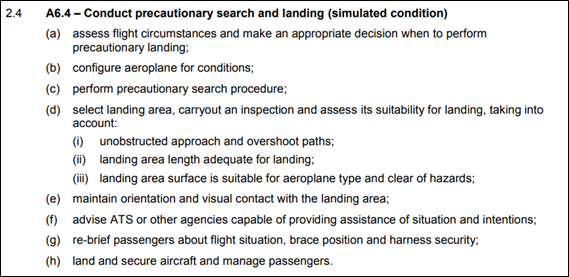
Figure 12: Extract from Schedule 2 ‘Competency Standards’ of Part 61 Manual of Standards dated 24/09/2018 page 126

Precautionary search height

The importance of the height selection for inspection runs during a precautionary search was articulated in the following paragraph 11.1.4 from Advisory Circular AC 91-0213:

It will be particularly important to consider appropriate heights to be able to conduct such a procedure safely, while remaining cognisant of potential engine failure considerations, especially if the requirement for a precautionary procedure was initially necessitated by an aircraft malfunction, low fuel state, or other related issue.

Further, for the inspection of the proposed landing path, page 59 the CASA Flight Instructor Manual (FIM)[15] stated:

This preliminary inspection should be sufficiently low for the surface to be inspected but not so low that it is necessary to avoid obstacles. Another point to impress on the student is that the inspection runs should be made at a constant height whilst safely avoiding upwind obstacles. If not satisfied with the surface complete at least one other inspection run at a lower height if necessary.

Further the FIM stated:

The need for a really good lookout whilst carrying out this low flying exercise cannot be over‑emphasised.

And

This exercise should be practiced only in approved areas or at approved fields and even then, all effort should be made to avoid frightening livestock and annoying people.

Inspection heights flown by OIS

During each circuit pattern the altitude of OIS varied, with flight data indicating that the pilots descended OIS during the southerly and easterly pattern legs before returning to a nominal height between 1,000 and 1,100 ft AGL. Based on the Soar guidance to instructors for use when conducting training exercises (referred to as patter notes), the inspection pass would have been the easterly facing leg of each circuit pattern (Figure 3). Each eastern facing leg was flown just over 1 km from the centreline of runway 07. Based on flight data for OIS, each inspection pass was flown at the following heights:

  • Pattern 1 (Figure 3 yellow lines): OIS descended to a minimum height of 750 ft AGL, and 400 ft above the ridge on the extended centreline for runway 07 (the ridge), during the easterly leg before returning above 1,000 ft AGL.
  • Pattern 2 (Figure 3 orange lines): OIS descended to 850 ft AGL (500 ft above the ridge) during the easterly leg before climbing above 1,000 ft AGL for the northern leg and descending throughout the western leg.
  • Pattern 3 (Figure 3 red lines): OIS levelled out between 450 and 475 ft AGL (100 to 125 ft above and 3.3 km from the ridge), before commencing a climb just after crossing over the extended centreline of runway 07/25 (start of pattern 3 in Figure 3). OIS continued to climb through the third easterly facing leg from about 500 to a peak height of 1,200 ft AGL mid‑way along the third northern leg. The flight instructor sought permission to conduct a touch‑and‑go from the property manager of Coombing Park ALA at some time along the southerly and/or easterly legs of this pattern.
Guidance in Aircraft flight manual for OIS

Under a section labelled ‘Emergency Procedures’, the AFM for OIS included guidance for the conduct of a precautionary search, stating that the inspection height shown be flown at an altitude above 500 ft. It is expected that this was intended to refer to height instead of altitude.

Section 2A2 of Soar’s operations manual stated ‘Where the Aircraft Flight Manual conflicts with other publications the Aircraft Flight Manual has precedence.’ However, the circumstances described in the AFM related to landing on an un-prepared field and did not include guidance for the conduct of a precautionary search and landing in normal operations or training.

Operator’s guidance

The operator produced guidance for instructors to use when conducting flight training exercises, referred to as ‘Patter Notes’. Under the patter notes for the demonstration of a precautionary search and landing, a series of 3 circuits were described, each with different heights to be flown. Each circuit was to be conducted at a nominated circuit height, with a descent during final approach to progressively lower heights for each circuit. The third circuit was listed as ‘only conducted if still uncertain about field conditions. After each circuit, the guidance suggested a climb back to the nominated circuit height.

The heights were listed in the patter notes as follows:

  • Circuit height (every circuit): 1000 feet AGL ([to] simulate [d an actual height of] 500 feet AGL)
  • First inspection pass: 1000 feet AGL ([to] simulate [d an actual height of] 500 feet AGL)
  • Second inspection pass: 700 feet AGL ([to] simulate [d an actual height of] 200 feet AGL)
  • Third inspection pass: 550 feet AGL ([to] simulate [d an actual height of] 50 feet AGL)

For each circuit, 2 sets of heights were presented, a higher, simulated set for the purpose of an exercise over an unprepared field (figures shown outside brackets above), and the other set relating to the actual heights to be flown for an effective inspection (shown within brackets). For example, the simulated height of the second inspection pass was 700 ft AGL, with the actual height listed in brackets as ‘simulated 200 feet AGL’. At the completion of the third circuit the guidance stated:

Turning final go around (if at an ALA or aerodrome, conduct short field landing).


In the event of a real prec search, short field landing, full stop landing. Do not taxi prior to walking the field.

At the conclusion of the precautionary search guidance, the patter notes stated:

Note: if conducting PSL at an ALA or aerodrome, actual heights may be used.

The ‘actual heights’ referred to are those listed inside the brackets above.

Other guidance

Guidance relating to the assessment of overshoot areas and the recommended heights that this assessment should be flown are included in various sources. However, the minimum height recommended for the conduct of an inspection run varied. Page 61 of the CASA FIM provided detail for the conduct of an air exercise by a flight instructor to demonstrate a practiced precautionary search and landing:

When in a suitable area descend to about 500FT above the ground and tell the student to assume poor weather conditions with a cloud base of about 600FT and poor visibility. Choose a suitable airstrip and demonstrate how to inspect the surface. Fly at low safe cruising speed with the optimum flap setting. Fly over the field slightly to the right of the intended landing path at about 100FT to make the first check. On this run check the surface and drift and note any high ground and obstacles in the overshoot area.

In ‘A pilot’s guide to safe flying’[16], for a precautionary landing procedure, this guide includes:

Confirm the acceptability of the landing area by carrying out an inspection run at 200 feet AGL (or well above possible obstructions), into wind, and slightly to the right of the intended landing area. Check out the following:

  • …
  • Obstacles, both on approach, and possible overshoot.
  • …

Guidance was also produced by the New Zealand Civil Aviation Authority[17]. For the first circuit, the guidance for the focus during the inspection includes:

On this and subsequent legs, …, with particular emphasis on surrounds in the approach and climb-out areas.

Guidance for a second inspection run stated:

Assuming the chosen landing site appears suitable up to this point, a second inspection is carried out at a minimum of 200 feet AGL.

…

Established on and parallel to final, a gradual descent to a minimum of 200 feet AGL is carried out.

Descent below 200 feet AGL is not recommended, because it takes considerable concentration to fly the aeroplane level and look at the landing site surface. Also, there is a possibility of unseen obstructions, and since a climb to 500 feet AGL will be initiated on completion of this inspection, the climb is minimised. Unless committed to the landing, never descend below the highest obstacle in the go-around path.

Selection of take-off and landing direction

Influence of wind

Pilots are required to choose the most suitable direction for landing and take-off when operating at any aerodrome. Generally, the main factor for this decision relates to the wind strength and direction. On a flat runway, a take-off or landing into wind (a headwind) will reduce the distance required in each case, whereas a tailwind will increase the distance required. For OIS, performance charts indicated that a tailwind component of 1 kt would lead to increases to the landing and take-off distances between 2.5‑2.8%. This equates to about 12 metres for the ground roll and a further 12 metres to clear a 50 ft obstacle per 1 kt of tailwind.

Influence of runway slope

In a section titled ‘Inclined runways’, Geeting and Woerner (1988)[18] stated:

Where possible, plan upslope landings and downslope take-offs.

This is because conducting a landing on a runway with an uphill slope reduces the landing distance required, whereas a take-off on an uphill slope increases the required take-off distance. An extract from guidance about Coombing Park ALA in the OzRunways applications described that the ‘airfield follows ground contour, rising to the east’. OIS conducted the touch-and-go in an easterly direction at Coombing Park ALA (runway 07).

For the landing component of the touch-and-go conducted by OIS, the tailwind condition (as described in the section titled Post accident weather analysis) and slight uphill runway slope had opposing effects on the landing distance. Estimations performed by the ATSB indicated that the deceleration advantage provided by an uphill landing at Coombing Park ALA was in a comparable range to the disadvantage provided by the tailwind.

The tailwind component was probably relatively low, based on the climb gradient of OIS being comparable to earlier climbs, and the pilots likely assessing the wind strength and direction from the two serviceable windsocks at the ALA. However, due to uncertainty in the actual wind conditions, it was not possible to determine the relative impact that the tailwind and the runway slope had on the touch-and-go length. Therefore, it was not possible to determine which runway direction would have provided the shortest distance for landing at the time of the accident.

During the take‑off phase of the touch-and-go, the tailwind and uphill slope would have both combined to increase the distance for OIS to become airborne. However, the touch-and-go length was comparable to others conducted at Orange earlier in the flight as discussed earlier, and it was again not possible to determine the relative contribution that the tailwind and slope had on the touch-and-go length. Once airborne however, the tailwind component would likely have had an adverse effect on the aeroplane’s climb gradient, although this could not be quantified.

Considerations for use of runway 25

Conducting a touch-and-go on runway 25 would have required the pilots to approach over the rising terrain and trees to the eastern end of the field. This would have required a steeper angle than the approach flown for runway 07, or for the pilots to touchdown part way into the runway. Due to the same uncertainty in the wind strength noted above, it was not possible to determine the length of a touch-and-go on runway 25, and the relative influence of a downhill landing or the headwind components.

The ATSB also considered the effect of conducting a standing take-off from each runway. For take-off on an inclined runway, Geeting and Woerner (1988)17 stated:

Always take-off downhill in light wind conditions. Acceleration is greater, less runway is required, and obstacles are cleared more easily. During take-off, a 1° downslope is roughly equivalent to having 10% more runway; a 2.5° upslope is equivalent to having a 7 kt tailwind during take-off.

For the take-off of OIS on runway 07, the tailwind conditions and uphill runway slope would have increased the distance required compared to a take‑off conducted on runway 25. Additionally, the final approach gradient of OIS to runway 07 was estimated to be about 6.5%, shallower than the climb-out gradient of about 7%.

Significantly, this indicated that OIS would likely have cleared all obstacles and terrain after a standing take-off from runway 25.

Operational information

Commercial pilot licence flight test assessment plan

Section 3D1 of the operations manual titled ‘Training Plans and Syllabuses’ stated:

Soar Advanced Flight Training has elected to use standard syllabuses, lesson plans and planning matrices prepared by CASA. These syllabuses are reproduced IAW those listed in Volume 5. In designing various courses, the school may vary the lesson times or add lessons in the syllabuses as required to be consistent with the training course in use.

This is consistent with interviews with instructors who stated that the CPL syllabus followed the requirements of Part 61 of the Manual of Standards.

Section 5A2.3 of the operations manual titled ‘Assessment plan’ stated.

A student may be deemed competent to conduct a solo flight, be recommended for a flight test or issued a qualification when competency is demonstrated on at least two occasions (each occasion being on a separate flight). Pre-solo and end of course assessments have been planned on this basis. End of course assessments take into account all of the units of competency mentioned in the Part 61 MOS for the licence, rating or endorsement.

Based on previous flights, this flight would have constituted the first of two pre-CPL flight assessments for the student. All units of competency mentioned in the Part 61 MOS for the commercial pilot licence would apply. This was consistent with a partially completed ‘Flight Test Report’ form 61-1490 found onboard the aircraft. Based on this, the assessment was to include diversions, aborted landings, practiced forced landings, short-field and flapless landings, and precautionary searches. Based on flight data for OIS, these exercises appear to have been performed during the accident flight.

Pilot roles and responsibilities

For this flight (and other training flights) with the student and instructor onboard, the flight instructor was the pilot-in-command. This is confirmed in section 3B1.17 of the operations manual titled ‘Instructor-student co-ordination’:

The Pilot In Command for dual training flights is the flight instructor. The flight instructor is responsible for ensuring that there is no doubt as to who has physical control of the aircraft at any given time; hence, the hand-over and take-over procedures shall be adopted for all dual training flights.

Further, section 3B1.1 of the operations manual titled ‘Authorisation of training flights’ stipulated:  ‘prior to despatching any training flight in a School aircraft, the Pilot in Command is to ensure that they have checked the following:

  • …
  • changes or restrictions concerning the use of the aerodrome and training area;
  • …

Therefore, for this flight, the operations manual confirmed that the flight instructor was expected to check if any restrictions existed with respect to using the Coombing Park ALA for flight training.

Pre-flight information

Purpose of flight

The purpose of the flight was for Soar to assess the competency of the student, prior to the student undertaking the CPL flight test (the pre-CPL assessment). The pre-CPL assessment was required by Soar for every student and acted as a final check to ensure that the student was ready for the actual flight test. Accordingly, the pre-CPL assessment flight was structured to include exercises for the student to demonstrate competency against the CASA CPL syllabus as directed by the flight instructor.

Flight arrangement by student

The pre-CPL assessment flight was intended to be conducted later in the week, however, on the morning of the flight, the student noted that the weather was suitable for flying and called Soar between 0830 and 0900 to ask if there were any senior instructors available. The student was informed that the instructor and an aircraft were available during the afternoon, and this was subsequently scheduled.

Just after this time at about 0900, the instructor likely started their shift as was typical for most days. The student left home at about the same time to drive to Soar at Bankstown Airport, with this trip typically taking between 40 to 50 minutes and the student likely arriving close to 1000. At 1145, the instructor conducted a dual training flight with another student involving a session of circuits at Bankstown Airport for just over 1 hour in duration.

Pre-flight preparations by student

At 1332, a flight plan was lodged for OIS using the National Aeronautical Information Processing System (NAIPS). This plan detailed a flight departing Bankstown at 1400 and tracking directly toward a set of coordinates just over 240 km to the west before returning to Bankstown Airport. These coordinates were 8 km south of the township of Greenethorpe (although lines that were drawn on flight charts were directly to the township) . The flight plan also stipulated a search and rescue time (SARTIME) for arrival at Bankstown by 1800.

Student likely unaware of actual waypoints

Prior to lodgement of the flight plan, other flight instructors at Soar reported that the student spoke with the instructor directly. Although it is not known what was discussed, it is expected that the discussion would have involved setting forward requirements for the flight to allow the student to lodge the flight plan and commence the flight. Therefore, it is not expected that the student was aware of the actual destinations or location of inflight diversions that occurred during the flight due to the exercises required by the CPL flight test. Further, it is unlikely that the student was aware that the flight would proceed to Coombing Park ALA.

Flight chart information

Pencil lines were found on the relevant world aeronautical chart (WAC) and visual navigation chart (VNC) located onboard the aircraft. Firm, straight lines between Bankstown Airport and Greenethorpe township indicated that the student had likely used Greenethorpe township for flight planning calculations and navigation. Lighter curvy pencil lines between the approximate location of the orbits and Orange Airport were also drawn on the WAC (the location of this inflight diversion is labelled in Figure 1) . These lines were likely drawn by the student inflight, consistent with being directed by the instructor to conduct an inflight diversion to Orange Airport.

A pencil line between Orange Airport through the south-west of Blayney on the WAC chart was drawn, intercepting the original planned route near the township of Burraga. This line was firmer and relatively straighter than the original diversion line, possibly indicating that this was drawn while the aircraft was on the ground at Orange, consistent with eyewitness and photographic evidence.

Coombing Park ALA was not marked on the charts used by the student, and there were no pencil markings identified on the WAC toward this region. This may indicate that the course deviation toward Coombing Park ALA after departing Orange Airport (shown in Figure 1) was a second inflight diversion exercise prior to the precautionary search and landing.

In summary, the pencil lines on the student’s flight charts were consistent with the student being unaware of the flight proceeding to Coombing Park ALA until after departure from Orange Airport. Further, there was no evidence that the student had been to Coombing Park ALA prior to this flight.

Operations to aeroplane landing areas

Company requirements

The Soar operations manual included guidance for flights to aerodromes, with section 3B1.5 titled ‘Aerodrome Suitability’ including the statement:

Except in an emergency, aeroplanes operated by Soar Advanced Flight Training will only be operated to or from aerodromes that are listed in En-Route Supplement Australia (ERSA) or Aeroplane Landings Areas (ALAs) that conform to the guidance provided in CASA publication CAAP 92-1(1).

The wording of this text was directly taken from that detailed in the CASA sample operations manual version 2.1 dated October 2016, which stated:

Except in an emergency, aeroplanes operated by [Sample Aviation Flight Training Pty Ltd] will only be operated to or from aerodromes that are listed in En-Route Supplement Australia (ERSA) or Aeroplane Landings Areas (ALAs) that conform to the guidance provided in CASA publication CAAP 92 1(1).

Further, under the section titled ‘Company register of suitable ALAs’, the operations manual included:

Form 4B13 (Aeroplane Landings Areas (ALA) Report Form) is to be used for compiling a company register of suitable ALAs of fixed wing aeroplane landing areas that are not listed in the ERSA, but have been approved by the HOO.
 

Information listed in the register is advisory in nature. The HOO should be advised if an amendment is considered necessary.

These requirements were in place in the Soar operations manual for at least one year prior to the accident and were included in the previous version of the operations manual, and possibly earlier iterations.

Form 4B13 contained fields to provide detail of the ALA, including a diagram of the landing area, and ALA characteristics including the slope, surface, elevation and obstructions. A signature box stating ‘Approved for company OPS’ was at the bottom of the form. This form could have been used to assess an ALA such as Coombing Park against the guidance of CASA publication CAAP 92-1(1), as required by section 3B1.5 of the operations manual.

At the time of the accident, Soar did not have a company register of suitable ALAs compiled.

Recommendations for aerial work and charter operations in CAAP 92-1(1)

Paragraph 8.2 of CAAP 92-1(1) stated:

A pilot should not use a landing area without taking all reasonable steps to ensure the physical characteristics and dimensions are satisfactory. For aerial work and charter operations the operator should provide evidence to the pilot on the suitability of a landing area prior to its use.

Soar Aviation’s Air Operator’s Certificate included approvals to conduct CASR Part 141 flight training. This was classified as an aerial work operation.

Scenario based training

Soar had 10 published scenarios that were available for use by their instructors for CPL training. These generalised scenarios allowed for any ‘suitable aerodrome’ to be used during the flight, with the aim to provide a more realistic training environment for students. Based on Soar’s operations manual, this included any ALA in the ERSA.

Certification standards for aerodromes

The CASA website included descriptions of 3 different categories of aerodromes under CASR Part 139. This included descriptions of where the standards were defined, and those responsible for certification of the aerodrome. For aeroplane landing areas, under the subject ‘Who is responsible for certification?’, the table noted these as an unregulated facility, with use to be:

in accordance with Aircraft Operators Certificate and/or pilot’s responsibility to determine suitability of the facility.

It was also noted that there were no defined standards, although guidance for use was included under CAAP 92-1.

Aeroplane landing area entry requirements into ERSA

All requirements for entry of an aerodrome into the ERSA related to the periodic review and provision of up to date data, covered under CASR Part 175.D as part of the Aeronautical Information Package (AIP).There were no requirements to demonstrate the suitability of ALAs listed in the ERSA, including assurance of obstacle clearance heights in the take-off and approach areas of each runway.

The CASA website included the question: ‘Are aerodrome details published in ERSA/NOTAM?’. For ALAs, this stated: ‘Airservices Australia may publish basic information for aerodromes that were previously regulated’. This was confirmed with Airservices personnel to potentially relate to some legacy aerodromes.

In response to an inquiry from the ATSB, CASA confirmed that the ERSA contained ALAs that may have been previously regulated and those ALAs that were not previously regulated. For previously regulated ALAs that did not transition to a certified standard, these were allowed to remain in the ERSA, but with operational information removed. In correspondence to the ATSB, CASA also clarified:

The exact content in the ERSA is between the aerodrome operator and Airservices Australia. However, runway distance data (LDA, TORA, TODA etc) is removed. Any flight operation/airspace information is CASA’s responsibility.

CASA also confirmed that there is no assurance of obstacle clearance for ALAs in the ERSA. CASA also noted that:

Pilot’s still have responsibilities for safe conduct of flight and minimum height rules.

The ERSA current at the time of the accident under the section ‘Aerodrome Information’ stated:


4.3 Aerodromes with limited information
 

a. Other aerodromes, also known as [Aeroplane] Landing Area (ALA) may be included in ERSA with limited information.

b. ALA are depicted in ERSA with a grey background as shown in INTRO.

c. Operators conducting regular public transport or charter operations into ALAs need to be aware of their obligations under the CASA regulations.

Prior to commencing a flight to an uncertified aerodrome, a pilot or operator must contact the Aerodrome Operator to ensure currency of aerodrome information.

Coombing Park ALA was eligible for entry into the ERSA at the time of the accident and could have been added by Airservices Australia if requested by the manager following compliance with CASR Part 175.

Discussion between instructor and manager of Coombing Park

Under the section titled ‘Company register of suitable ALAs’, the Soar operations manual also included:

The PIC must obtain permission to use the ALA when required and is responsible for determining that the area is suitable for the intended operation.

The property manager of Coombing Park recalled that, just after the pilots commenced the third precautionary search pattern overhead the ALA (indicated by ‘Pattern 3’ in Figure 3), they received a phone call from a person identifying themselves as a flight instructor from Soar. Telephone records identified that the duration of the call was 24 seconds, commencing at 1704. The property manager, who was in the vicinity of the runway, could see and hear OIS in the circuit area and confirmed with the instructor that it was them in the circuit area.

The property manager recalled that the instructor asked, ‘Do you mind if I do a touch‑and‑go?’ The property manager reported that based on:

  •  the instructor identifying themselves as a flight instructor
  • OIS already being in the circuit area
  • the manager assuming that OIS was going to land on runway 25
  • a desire not to distract the pilots further

 the property manager granted the instructor permission to land without further discussion.

The property manager reported that normally, people called up an hour or so ahead of time, and that advice on local procedures and potential hazards was provided. The manager also reported that this was the first time they had spoken with the flight instructor and couldn't recall talking to anyone from Soar Aviation in the past.

Instructor familiarity with Coombing Park

Staff members representing Soar reported that the flight instructor may have been familiar with Coombing Park ALA. However, the precise nature of the instructor’s interactions with the ALA were not known. Further, it was reported that Soar previously held a register of ALAs that included Coombing Park. It was reported that this register had been misplaced, possibly during an office move, and was unable to be provided to the ATSB for review.

The ATSB examined data from flights previously conducted by the flight instructor to evaluate any previous instances of operating in the circuit area of Coombing Park ALA, and any other ALAs. This analysis used data stored in the flight instructor’s OzRunways account, and publicly available location data for ERSA and non-ERSA ALAs, including Coombing Park. The flight instructor’s data was limited to times when the instructor was using the OzRunway mobile phone application and the phone was in range of a telecommunications tower.

Limitations in the accuracy and fidelity of the available data prevented identification of whether a landing occurred at any of the locations. Flights to ALAs within range of Bankstown Airport and flown past within 5.5 km (indicating the 3 nm circuit area) by the instructor were of particular interest (Figure 13).

Figure 13: Aeroplane landing areas within range of Bankstown Airport and within 5.5 km of flights conducted by the instructor between 2016 and 4 November 2020
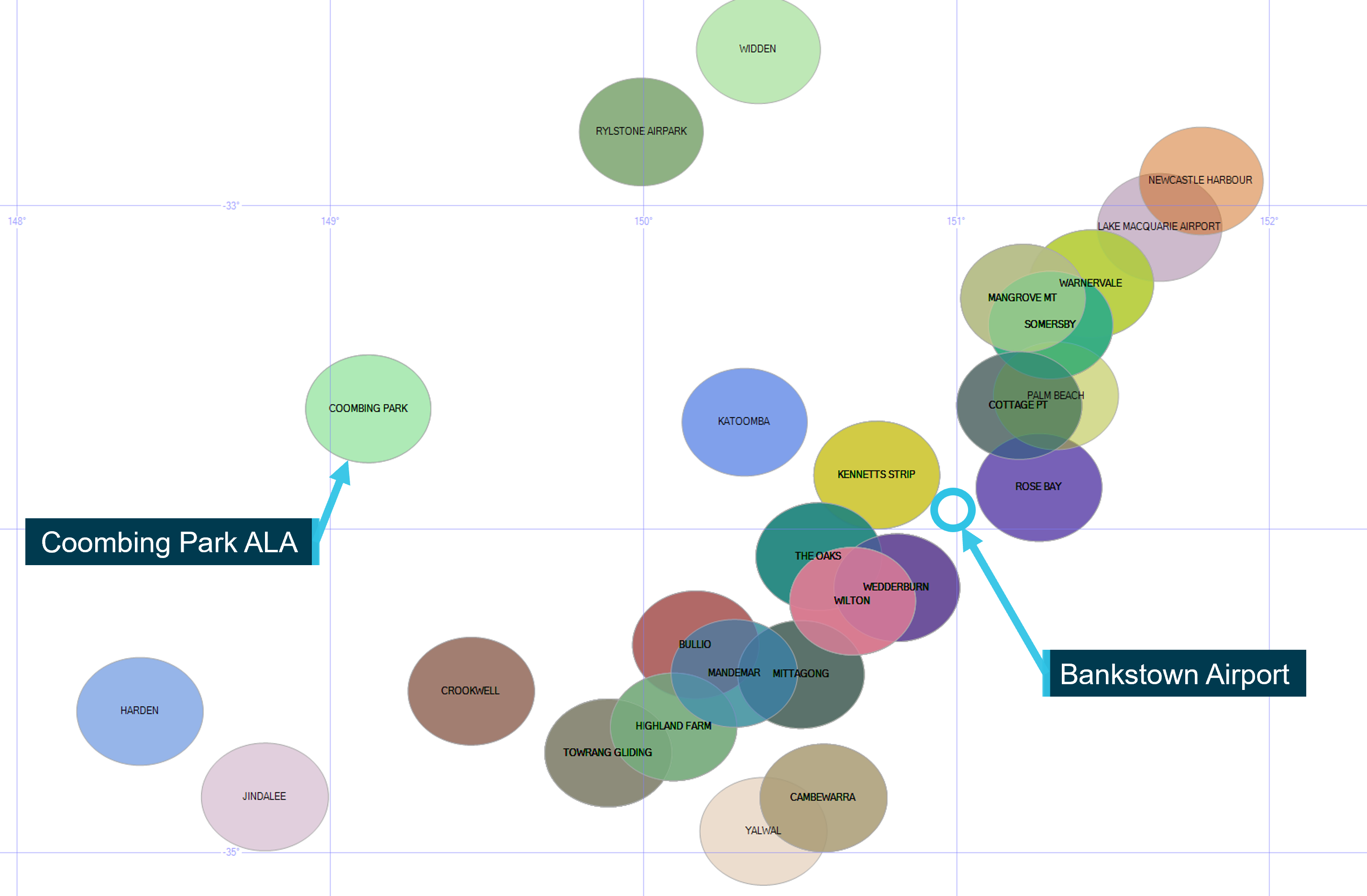
Figure 13: Aeroplane landing areas within range of Bankstown Airport and within 5.5 km of flights conducted by the instructor between 2016 and 4 November 2020

Image showing relative location of ALAs flown past by the instructor compared to Bankstown Airport and Coombing Park ALA

Source: ATSB

The analysis revealed that the instructor passed at least 59 ALAs at least once from a total of 138 flight data files between 2016 and the time of the accident. Forty-three of these ALAs were located in New South Wales, 10 in Queensland and 6 in Victoria. Approximately half of these ALAs (30) were not included in the ERSA, with the remaining 29 ALAs being listed. The flight data revealed that for most flights there was no evidence of the aircraft joining the circuit pattern at these ALAs, however, these locations were sometimes used as waypoints, characterised by a change in direction of the aircraft track. The most common locations passed were on the eastern side of the Great Dividing Range and between Newcastle to the north and Goulburn to the south.

Coombing Park was passed once by the instructor on 21 September 2018, with 2 heading changes occurring as the aircraft passed overhead (Figure 14). However, there was no evidence to suggest that any circuit or landing (including a precautionary search) was conducted at that time. No other evidence was identified for flights by the instructor to Coombing Park.

Figure 14: Flight by the instructor within 5.5 km of Coombing Park on 21 September 2018
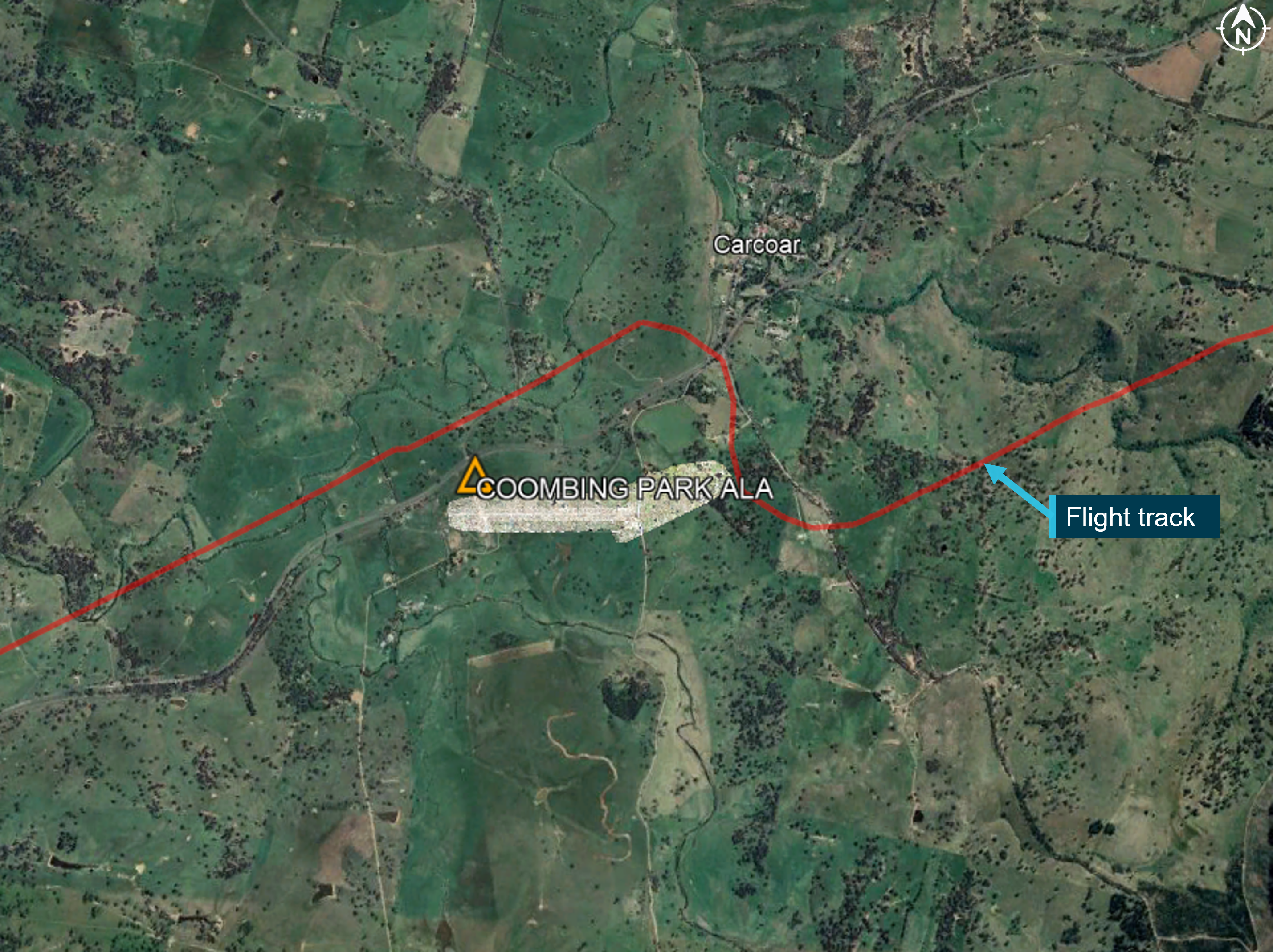
Figure 14: Flight by the instructor within 5.5 km of Coombing Park on 21 September 2018

Image showing top down map of Coombing Park ALA and Carcoar township. Red line depicts the flight track.

Source: Google Earth, annotated by the ATSB

There were 2 occasions identified where precautionary searches likely occurred at ALAs (Mangrove Mountain ALA and The Oaks ALA), with a landing possibly occurring at The Oaks. The flight data also indicated that a precautionary search was likely conducted at Mangrove Mountain ALA, a non-ERSA ALA on 3 November 2018.

In this case, the flight track did not pass along, or directly approach the runway, indicating that a landing did not occur. One flight, on 14 January 2017 indicated that the Oaks ALA (which was included in the ERSA) was likely used for a precautionary search and landing. In summary, the instructor’s previous flights stored by OzRunways did not provide evidence of any previously conducted landings at non-ERSA ALAs.

Civil Aviation Advisory Publication 92-1(1) Guidelines for aeroplane landing areas

As detailed previously, the Soar operations manual only allowed operations to non-ERSA ALAs when they had been assessed to conform to the recommendations in Civil Aviation Advisory Publication (CAAP) 92-1(1) - Guidelines for aeroplane landing areas (the CAAP), and this had been approved by Soar’s head of operations. Such an evaluation of Coombing Park ALA had not been performed by Soar.

CAAP 92 overview

At the time of the accident, the introduction of the CAAP, released in July 1992, noted:

This publication sets out methods that may be used and which experience has shown should, in the majority of cases, ensure compliance with the Regulations. However, before using the information in this publication the user should always read the Civil Aviation Regulations listed…’

The CAAP then stated:

These guidelines set out factors that may be used to determine the suitability of a place for the landing and taking-off of aeroplanes. Experience has shown that, in most cases, application of these guidelines will enable a take-off or landing to be completed safely, provided that the pilot in command: (a) has sound piloting skills; and (b) displays sound airmanship.

CAAP 92 assessment of Coombing Park

The ATSB assessed Coombing Park ALA against the obstacle clearance recommendations of the CAAP. This recommended the ‘approach and take-off areas to be clear of objects above a 5% slope for day...operations’. This was an area extending 900 m beyond the end of the runway and is illustrated in Figure 15. The accident flight path was within this area prior to the final left turn (Figure 10).

Figure 15: Summary of eligibility requirements for ‘other’ physical characteristics of a CAAP 92-1(1) aeroplane landing areas
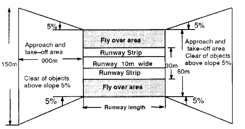
Figure 15: Summary of eligibility requirements for ‘other’ physical characteristics of a CAAP 92-1(1) aeroplane landing areas

Source: Civil Aviation Safety Authority, CAAP 92-1(1) ‘Figure 2A – Single engined [sic] and Centre-Line Thrust Aeroplanes not exceeding 2000 kg MTOW (day operations)’

Table 1 shows Coombing Park ALA compared to the minimum recommended requirements of the CAAP for the approach and take-off area slope. The 2 left-most columns show the required CAAP value and relevant characteristic, with the 4 right-most columns relating to measurements conducted for Coombing Park ALA. Three sets of measurements were conducted for Coombing Park ALA based on the actual runway length, and characteristics if the runway length was shorter. The purpose of the theoretical measurements was to examine if the minimum recommended obstacle clearance requirements of the CAAP could be met at Coombing Park if runway 07 was shortened, increasing the distance between the runway 25 threshold and the rising terrain and obstacles to the East of the field.

Runway length requirements (CAAP 92(1)-1 Clause 5.1) and theoretical shortened runway calculations were based on 2 scenarios. The first scenario labelled ‘Theoretical shortened runway– AT01 Nil wind TODR [take‑of distance required]’ simulated a scenario where the runway was shortened to match the take-off distance required for VH-OIS on the day of the accident in nil wind. This represents a baseline scenario.

This calculation was based on VH-OIS performance charts for the estimated density altitude on the day of the accident, with an increase of 25% length for a short dry grass surface at Coombing Park. This data was considered ‘factored’ for the purpose of CAAP 92(1)-1 clause 5.1 that recommended an additional 15% be added to the length when using ‘unfactored’ data. The other scenario labelled ‘Theoretical shortened runway– worst case standing take-off’ is the result of a 5% slope applied from the location of the longest estimated standing take-off (836 m), as described in the section titled Evaluation of touch‑and‑go length and shown in Figure 7.

Table 1: Partial comparison of Coombing Park ALA to recommended minimum physical characteristics of landing areas according to CAAP 92-1(1) section 5 for Aquilla AT01 day operations

CAAP 92 recommendationsCoombing Park Measurements   
(Clause) CharacteristicRecommended valueEstimated 4 Nov 2020 stateTheoretical shortened runway – AT01 Nil wind TODRTheoretical shortened runway – worst case standing take-off
Runway length1200m661m850m 
(5.5) Approach and take-off area slopeNo obstacles above 5% out to 900 m beyond thresholdTake-off slope surface penetrated terrainTake-off slope surface clear of terrain, possibly penetrated treesTake-off slope surface clear of terrain, likely penetrated trees

The assessment against CAAP 92-1(1) recommendations revealed that Coombing Park ALA likely did not meet obstacle clearance recommendations for VH-OIS at the time of the accident. Approach and take-off area slopes are illustrated in Figure 16 relative to the terrain profile (and upwind climb profile of OIS for reference), as also shown in Figure 7. These slopes are shown by the yellow, blue and orange lines, and have labels prefixed with ‘CAAP 92 surface...’ in Figure 16. Each of the 3 obstacle clearance slopes terminated 900 horizontal metres from the (simulated and actual) runway ends, as per the recommendations in CAAP 92-1(1). For reference, the horizontal axis shows the distance from the start of runway 07, corresponding to figures shown earlier. This shows that the CAAP 92-1(1) obstacle clearance surface originating from the end of runway 07 penetrated the rising terrain about 150 m from the runway end (orange line), as also noted in Table 1.

Figure 16: CAAP 92(1)-1 Runway approach and take-off obstacle clearance slope from various theoretical runway end positions projected onto the terrain profile of Coombing Park ALA compared to actual climb performance of VH-OIS
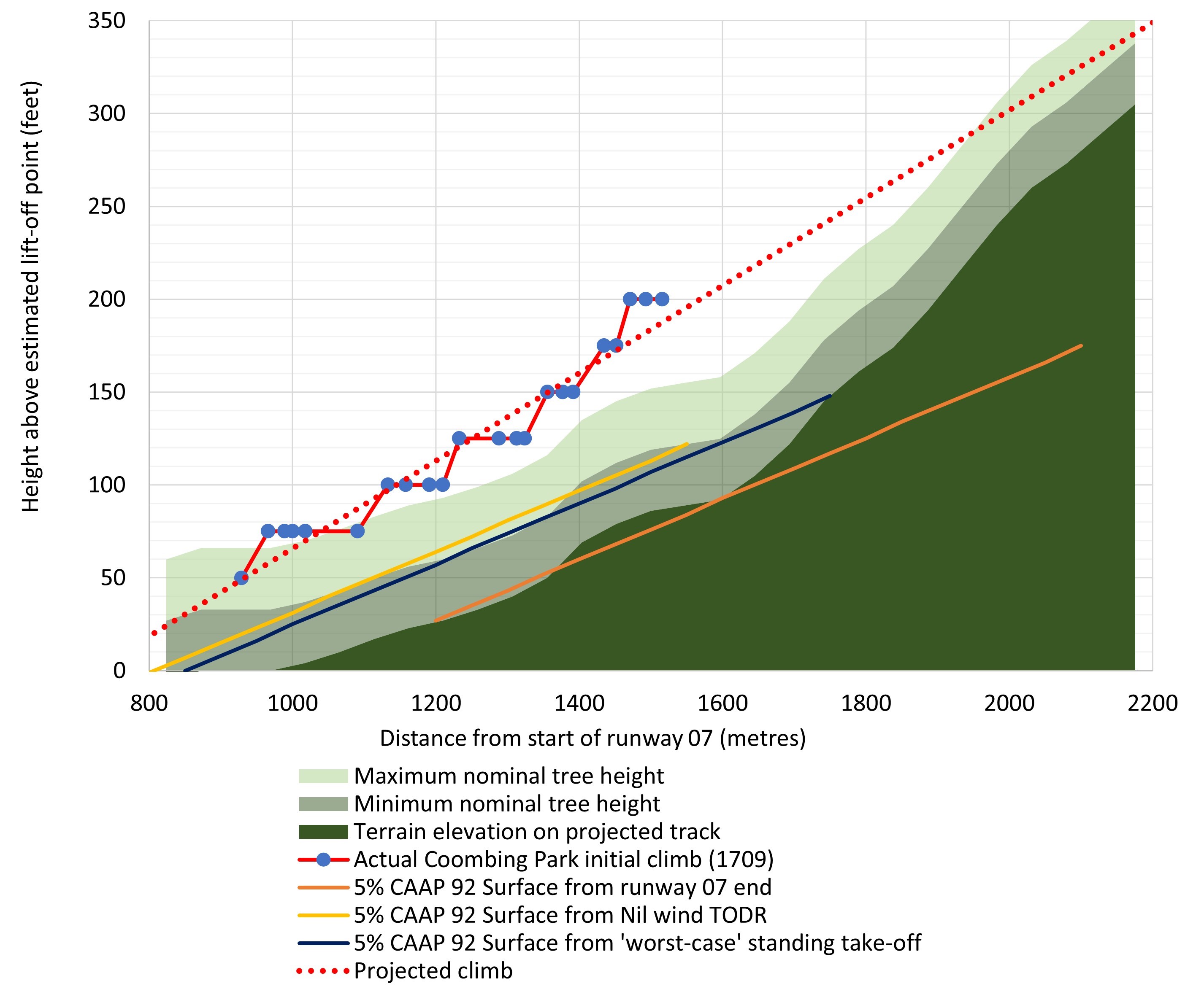
Figure 16: CAAP 92(1)-1 Runway approach and take-off obstacle clearance slope from various theoretical runway end positions projected onto the terrain profile of Coombing Park ALA compared to actual climb performance of VH-OIS

Figure showing plot of height vs distance travelled of OIS during the initial climb from Coombing Park ALA runway 07 compared to terrain and projections for the CAAP 92 obstacle clearance slope

Source: ATSB

The approach and take-off slope originating from the theoretical ‘nil wind’ shortened runway distance (shown in yellow) did not intersect with the terrain within the 900 m horizontal limit. However, this may have intersected with some of the trees in this area, and the projection of the shortened runway slope intersected the rising terrain approximately 250 m beyond this point.

The approach and take-off slope from the estimated worst-case standing take-off for VH-OIS is also shown in Figure 16 by the blue line. This also shows that the approach and take-off slope may have passed the CAAP 92 recommendation for a 5% obstacle clearance within 900 m, although this intersected with the terrain almost immediately after this point. However, it is likely that trees in this area would have penetrated this slope. Note that the CAAP 92 slopes from both theoretical shortened runways shown in Figure 16 correspond to theoretical take-offs shown in Figure 7 of the same colour.

Related occurrences

The ATSB’s national aviation occurrence database was reviewed to identify accidents and serious incidents involving collisions with terrain at ALAs that were reported to the ATSB in the 30 years between 1991 and 2020. These records were refined to occurrences where the characteristics of the runway and surrounding terrain may have influenced the outcome. In total 9 occurrences were identified meeting these criteria over this period.

Three of the occurrences identified related to ALAs listed in the ERSA and were therefore approved for use by Soar’s operations manual. One of the 3 ALAs were located at a similar or shorter distance than Coombing Park ALA was to Soar’s base of operation at Bankstown Airport (within range of Soar). A summary of these occurrences is below.

  • ATSB investigation AO-2018-025 Runway excursion and collision with terrain – Van’s RV-6A, VH-OAJ, Somersby ALA, New South Wales on 18 March 2018. This investigation found that features surrounding the runway, including undulating terrain and a small watercourse immediately at the end and trees at the edge, increased the likelihood and severity of occupant injury in the case of a runway excursion. And further, that CAAP 92-1(1) did not have guidance for the inclusion of a safe runway overrun area.
  • ATSB occurrence 200903966 Collision with terrain involving a Piper Aircraft Corp PA-31, Bungle ALA (Bellburn), Western Australia on 06 June 2009. During final approach to runway 10, the aircraft's right wing tip struck a tree branch, causing minor damage to the leading edge. This was a commercial charter flight with one pilot and 9 passengers onboard. A review of the approach area to runway 10 at Bungle ALA did not reveal any significant undulation in terrain, however there appeared to be slight height variation near the runway threshold. This ALA was in the ERSA and the occurrence is also notable because it relates to a charter operations to an ALA in the ERSA that was not assured as meeting CAAP 92-1(1) obstacle clearance recommendations.
  • ATSB Occurrence 199700351 Collision with terrain involving an unknown ultralight aeroplane, Coominya ALA, Queensland on 9 February 1997. The pilot was attempting an uphill take-off. Soon after becoming airborne, the pilot reported becoming concerned about the closeness of the trees off the end of the runway. The pilot commenced a 180-degree turn, although the aircraft struck trees before the turn was completed. Subsequently, the aircraft struck the ground nose first and the pilot received serious injuries during the impact.

A further 2 occurrences were identified by the ATSB that were within range of Soar but were not listed in the ERSA. Therefore, these aerodromes were not approved for use for Soar operations without further risk assessments being conducted. These occurrences appear to be related to either obstacles and or terrain in the take-off and landing areas. These are of note because all aerodromes were eligible for entry in the ERSA (subject to a risk assessment), making them approved for use by the Soar operations manual.

  • ATSB investigation AO-2018-013 Collision with terrain involving Cessna 206, VH-WZX, Apollo Bay ALA, Victoria on 31 January 2018. There was a pilot and 5 passengers on board. The ATSB found that a go-around commenced late during the landing and the pilot did not immediately follow the go-around procedure. These factors, combined with the heavy aircraft weight and rising terrain, reduced obstacle clearance and the aircraft struck the airfield boundary fence.
  • ATSB Occurrence 201901041 Collision with trees involving Piper Aircraft Corp PA-38, VH‑CNT, Currandooly ALA, New South Wales on 23 February 2019. During the initial climb, the aircraft was unable to outclimb rising terrain and stuck trees. The aircraft subsequently collided with terrain resulting in substantial damage to the aircraft and minor injuries to the pilot. The occurrence is notable because the sequence of events and terrain appear similar to the accident scenario for VH-OIS. The aerodrome was within range of OIS from Soar’s base of operations at Bankstown Airport.

Safety analysis

Introduction

While conducting an assessment in preparation for a commercial pilot’s licence flight test, an Aquila AT01 registered VH-OIS (OIS), conducted a precautionary search at Coombing Park Aeroplane Landing Area (ALA), about 27km south of Orange Airport, New South Wales. Flight data indicated that after three precautionary search patterns were flown, a touch‑and‑go was conducted, with the aircraft climbing toward rising terrain after take-off. As the aircraft approached an area of steeper terrain, a climbing left turn was conducted toward a slightly lower and less wooded area. The aircraft continued to fly in a controlled manner, likely accelerating and descending slightly toward an open area of rising terrain beyond a small dam. After flying over the dam, the aircraft collided with an embankment, bordering the dam and the open area.

Site and wreckage examination, and aircraft performance assessments did not identify any defects, anomalies or sudden performance loss that might have contributed to the accident. Additionally, no evidence was found to suggest any medical or fatigue related issues that would have affected the pilots’ performance on the day of the flight. Therefore, this analysis will focus on the operational factors that led to an experienced flight instructor and a commercial student pilot to conduct a touch‑and‑go toward rising terrain that the aircraft was unable to outclimb.

Development of the accident

Pre-flight planning

Due to the nature of the flight, in preparation for the commercial pilot licence flight test, only the instructor is likely to have been aware of Coombing Park ALA being a waypoint for the flight prior to departure, although it is not known if a landing was originally planned by the instructor. Coombing Park ALA was not listed in the ERSA and therefore, use of the ALA for landing was not approved by the company operations manual without further assessment, which had not been performed. This requirement was likely known to the instructor as it had been in the operations manual for at least one year. For this accident, if this procedure was followed, the aircraft would not have landed.

It was reported by staff at Soar that a previous register existed which contained Coombing Park ALA as an approved aerodrome. However, this register could not be provided to the ATSB. Further, if a risk assessment was performed by Soar for Coombing Park ALA previously, it is unlikely that it would have been identified as suitable for conducting a landing. This is due to the rising terrain to the east not meeting the recommendations of CAAP 92-1(1). It is also considered likely that the flight instructor would have reached the same conclusion if this hazard was assessed prior to flight.

It was also reported that the flight instructor was likely familiar with the ALA. This is consistent with one previous flight identified by the ATSB, where Coombing Park ALA was likely used as a waypoint by the instructor. However, there were no flights identified where the instructor conducted a precautionary search or landing at Coombing Park ALA. Therefore, there was no evidence that suggests the instructor had an opportunity to effectively assess the rising terrain hazard for conducting a take-off, touch-and-go or landing at Coombing Park ALA in previous flights.

The flight instructor contacted the manager of Coombing Park ALA to seek permission to conduct a touch-and-go while OIS was in the circuit area after 2 complete precautionary search patterns. This phone call only lasted 24 seconds. This was the only telephone call that the manager of Coombing Park ALA received from the instructor that day and could not recall receiving a phone call from any instructor from Soar in the past. The manager of the ALA reported that they usually provided a more in depth briefing for people calling ahead of time. This likely represents a missed opportunity to gain a knowledge of present conditions, operating procedures and hazards to be aware of.

It should be noted that until the point where the decision was made to conduct a touch-and-go, the flight had proceeded as expected. This included conducting the precautionary search patterns. Although it could not be confirmed, it is likely that the instructor considered the risk of a touch-and‑go to be low. This was likely based on Coombing Park ALA having a sufficient runway length for a landing (not a touch-and-go). It was not established if the instructor had intended on flying to Coombing Park ALA before the flight. However, the timing of the phone call to seek permission to conduct a touch-and-go after completion of two precautionary search patterns, may indicate that the decision to conduct a touch-and-go by the instructor was a last-minute decision. This was possibly under a motivation to provide a realistic experience for the student.

Overall, it is likely that if the suitability of conducting a touch-and-go at Coombing Park ALA was assessed prior to flight, the instructor would have identified Coombing Park ALA as unsuitable for landing. Therefore, it is expected to be likely that there was limited planning conducted prior to the flight with respect to assessing the suitability of Coombing Park ALA for a landing, take-off or touch‑and‑go. It is also possible that the decision to conduct a touch-and-go was an impromptu deviation from the original plan. Further, the lack of planning, or deviation from the original plan, removed a defence, placing more pressure on assessments in flight (which were also ineffective). These factors reduced assurance that the aircraft could outclimb the rising terrain, which subsequently led to the accident occurring.

Conduct of precautionary search

The southerly and easterly legs of each precautionary search pattern flown at Coombing Park ALA likely provided the best opportunity for the pilots to identify the rising terrain hazard to the east.  

The easterly inspection legs running parallel to the runway in the direction of landing were the inspection runs, For the duration of the third easterly leg, OIS was in a climb from 500 to 800 ft AGL, about 150 to 450 ft above the ridge and over 1 km to the right of the runway centreline. During this leg, the elevated nose position of OIS would have likely made assessing the rising terrain more difficult. Additionally, the changing perspective of the terrain may have been more apparent if the aircraft was in a straight and level configuration. In the two earlier patterns, the easterly legs were flown at more than 750 ft AGL, more than 400 ft above the ridgeline. Further, in all legs, OIS was more than 1 km to the right of the runway centreline, reducing the opportunity for the pilots to assess the overshoot area (and the runway surface).

At the start of the third pattern while tracking on the southerly leg (the third southern leg), OIS descended to a minimum height of about 450 ft AGL. Although this leg was only about 100 ft above the ridgeline on the extended centreline for runway 07 (the ridge), it was 3.3 km away from OIS.

Southerly legs were not considered inspection runs in the Soar ‘patter notes’ (these were the eastern legs), with these inspection runs noted to be flown at the lowest heights during the precautionary search patterns. Despite this, the third southern leg was flown at the lowest height of any legs at Coombing Park ALA during the precautionary search, prior to the final approach for the touch-and-go. This was at least 250 ft higher than recommended by the Soar ‘patter notes’ when conducting an actual precautionary search inspection run. This guidance was generally aligned with procedures for other organisations.

It is expected that the perspective offered by the ridge being slightly below the aircraft and more than 3 km away on the third eastern leg, reduced the likelihood that the pilots would identify this as unsuitable for take-off from runway 07. Further, the (easterly) inspection runs were flown at heights above the ground and offset positions from the runway centreline that likely reduced the pilots’ ability to detect the significance of the ridge at the end of runway 07 for take-off.

Therefore, it is likely that the heights and positions of OIS during the precautionary search patterns flown at Coombing Park ALA likely limited the opportunities for the pilots to detect the rising terrain hazard at the end of the runway, contributing to the decision to conduct a touch-and-go.

Take-off direction

It is likely that the ideal direction for landing and take-off were in opposite runway directions at Coombing Park ALA at the time of the accident. For landing, the light tailwind on runway 07 was countered by an uphill slope. Therefore, it is possible that either runway 07 or runway 25 would have allowed the shortest landing distance. However, there were fewer obstacles on approach to runway 07, likely making the approach less demanding on the pilots compared to runway 25.

The headwind component and downhill slope on runway 25 indicated that using that runway for a standing take-off would likely have allowed OIS to take-off in a shorter distance along the runway compared to runway 07. Further, due to no significant obstacles beyond the end of runway 25, it is very likely that OIS would have been able to safely climb away after lift-off. Finally, a standing take-off on runway 25 would have allowed OIS to start the take-off roll from the beginning of the runway, allowing the entire length to be used.

Therefore, a landing on runway 07, followed by a standing take-off on runway 25 would have likely prevented the accident.

The ATSB conducted further analysis (described in the next section) for a standing take-off compared to a touch-and-go on runway 07. This indicated that OIS may have been able to clear the terrain if a standing take-off was conducted on runway 07.

Touch-and-go

All touch-and-goes conducted by the student at Orange Airport likely used more runway than the standing take-off at Orange Airport (based on the distance from the runway threshold to the end of the take-off (where the aircraft climbed to 50 ft)). The touch-and-go conducted at Coombing Park ALA was likely typical of those conducted at Orange, with the approach reported by an eye‑witness as appearing normal. Based on flight data and calculations from the aircraft flight manual for OIS, the estimated standing take-off length at Coombing Park was estimated to be between 630 and 836 m, shorter than the actual touch‑and‑go length of 929 m. Therefore, it is very likely that a standing take-off would have led to OIS becoming airborne earlier along runway 07, reducing the likelihood of a collision with terrain.

There are more factors involved with the conduct of a touch-and-go compared to a standing take-off. This is supported by available literature and flight data for OIS that indicated a higher variability and longer length rolls from every touch-and-go compared to a standing take-off. This supports that there is likely less consistency with the length of a touch‑and‑go compared to a standing take-off.

ATSB analysis identified that the reduced runway length required by conducting a standing take-off at Coombing Park ALA was estimated to increase the height of OIS between a worst-case of 22 and a best-case of 70 ft at each point in the initial climb. This would have increased the margin between OIS and the terrain, in particular the trees. Adding the worst-case standing take-off height gain (22 ft) to the projections for the touch-and-go for different initial climb routes shows that all climb routes would have likely cleared the terrain by a greater height than the trees.

For a worst-case standing take-off, these estimations predicted these initial climb options pass the terrain by about 67 ft if tracking on the runway centreline up to 92 ft if a flight up the gully was conducted. The options to turn right, continuing the left turn, or climbing away from overhead the dam were all predicted to the terrain by a minimum of 88 ft. However, based on these estimations, and the maximum nominal height of trees being about 66 ft, it should be noted that any escape flight path would have still been at a very low height.

Therefore, the additional height offered by the worst-case standing take-off would have likely provided more options to the pilots, likely allowing the pilots to climb away from the terrain.

Forced landing

During the initial climb, the aircraft was likely performing normally. A projection of the flight path for OIS on the original track during the initial climb showed the aircraft likely would have collided with trees if flight was continued in that direction. It is likely that the pilots realised that the aircraft would be unable to outclimb the terrain and elected to turn left toward terrain that was less steep. Flight data analysis indicated that it was unlikely the pilots could have continued the left turn or conducted a right turn without colliding with trees. The aircraft rolled level flying toward the small dam, with flight data indicating that the aircraft was likely accelerating and descending just prior to crossing the surface of the dam. This indicates that the aircraft was likely in a controlled state at this point, about 1 second prior to impact. Based on this data, possibly after realising they would be unable to out climb the terrain, it is likely that the pilots were attempting to gain airspeed to affect a transition for an uphill forced landing. There was also likely minimal time for the pilots reconfigure the aircraft for a forced landing. During this attempted forced landing, the aircraft collided with the embankment of the dam.

Operator’s procedures

Soar's operations manual allowed training flights to be conducted to any aerodrome deemed suitable as part of a scenario-based training program. All aerodromes listed in the ERSA were considered as suitable for flight training operations. Therefore, Soar procedures did not require further assessment of ALAs listed in the ERSA. Further, for entry and ongoing listing in the ERSA, ALAs did not require any assessment of aerodrome suitability for aircraft operations.

In contrast, to be considered as suitable for flight training operations, ALAs not included in the ERSA were required to be assessed and found to meet all recommendations in CAAP 92-1(1). Therefore, Soar’s operations manual was inconsistent in the treatment of operational hazards between operations to ALAs listed in the ERSA and non-ERSA ALAs. This means that there were fewer controls in place to assure that obstacle clearance surfaces were suitable for use by Soar at ALAs listed in the ERSA.

Based on Soar operating in the aerial work category, the guidance in CAAP 92(1)-1 was suggesting that Soar would be expected to provide evidence to pilots on the suitability of landing areas. Although Coombing Park ALA was not in the ERSA, it was eligible to be without any further assurance that it was suitable for use by Soar. This is important because this ALA could have been approved for Company operations and would have resulted in the accident occurring at an ALA considered as suitable for company operations.

In summary, the CASA sample operations manual wording adopted directly by Soar Aviation provided approval for operation to ALAs in the ERSA without providing evidence and assurance that these were suitable for use by company aircraft.

CAAP 92 Recommendations

The Soar operations manual required that all ALAs not in the ERSA be assessed against the recommendations of CAAP 92-1(1) prior to use. Although this assessment was not performed for Coombing Park ALA, it could have been.

Section 5.5 of CAAP 92-1(1) included the recommendation that the terrain be clear of objects above a slope of 5% up to a distance of 900 m, however, there was no requirement for obstacle clearance beyond this distance. Coombing Park ALA had terrain that became steeper away from the runway. These circumstances may lead to situations where an aircraft is unable to safely climb away from the runway, despite the ALA meeting CAAP 92-1(1) obstacle clearance recommendations. There is also no assurance that other ALAs do not exist with these characteristics.

Coombing Park ALA did not meet the CAAP 92-1(1) recommendations for obstacle clearance beyond runway 07. However, if runway 07 was shortened, increasing the distance by displacing the runway 25 threshold, but still remaining at a suitable length for use by the accident aircraft, it is possible that the ALA would have met these recommendations. With the displaced runway 25 threshold, the ALA would likely have met these recommendations if several trees were removed from the take-off and approach area at the end of runway 07.

ATSB analysis showed that if the accident aircraft had conducted a standing take-off, it probably would have cleared the trees and terrain during the upwind climb by a very narrow margin. This situation would have been worse in an aircraft meeting minimum climb gradient requirements.

In summary, the CAAP 92-1(1) guidance did not assure that an aircraft would be able to safely outclimb rising terrain located more than 900 m from the end of a runway. This would have applied at Coombing Park ALA if the runway ended near the point of lift off.

Findings

ATSB investigation report findings focus on safety factors (that is, events and conditions that increase risk). Safety factors include ‘contributing factors’ and ‘other factors that increased risk’ (that is, factors that did not meet the definition of a contributing factor for this occurrence but were still considered important to include in the report for the purpose of increasing awareness and enhancing safety). In addition ‘other findings’ may be included to provide important information about topics other than safety factors. 

Safety issues are highlighted in bold to emphasise their importance. A safety issue is a safety factor that (a) can reasonably be regarded as having the potential to adversely affect the safety of future operations, and (b) is a characteristic of an organisation or a system, rather than a characteristic of a specific individual, or characteristic of an operating environment at a specific point in time.

These findings should not be read as apportioning blame or liability to any particular organisation or individual.

From the evidence available, the following findings are made with respect to the collision with terrain involving Aquila AT01, VH-OIS, Coombing Park ALA, 27 km south of Orange Airport, New South Wales, on 4 November 2020.

Contributing factors

  • It is likely that pre-flight planning was not performed to ascertain the take-off area was clear of obstacles at Coombing Park ALA as required by the operations manual. Consequently, this reduced assurance that the pilots would identify and mitigate the risk of rising terrain that the aircraft was unable to outclimb at the end of runway 07.
  • The pilots were conducting the precautionary search at heights and positions that would have likely made assessing the hazard of rising terrain from the air less effective. This likely contributed to the pilots’ decision to conduct a touch-and-go landing and take-off toward rising terrain that exceeded the climb performance of the aircraft and required a low-level turn to avoid rising terrain.
  • The take-off was conducted on an uphill slope with a probable tailwind and toward rising terrain beyond the runway end. A standing take‑off conducted in the more favourable reciprocal direction would likely have cleared all obstacles and terrain.
  • The conduct of the touch-and-go, rather than a standing take-off, reduced assurance that the aircraft would commence the climb from a position along the runway that could clear the terrain during the initial climb after take-off.
  • The combination of loss in climb performance during the turn, trees and rising terrain in the new direction likely led to the pilots conducting an uphill forced landing. It is likely that the aircraft had insufficient performance for the uphill forced landing, leading to the aircraft colliding with the embankment of a small dam.

Other factors that increased risk

  • The CASA sample operations manual used by the operator that allowed any aerodrome in the Enroute Supplement Australia to be used for flight training did not assure that these aerodromes were suitable for use. (Safety Issue)
  • Recommendations in CASA guidance CAAP 92-1(1) requiring obstacle clearance out to 900 m may lead to circumstances where ALAs meet these requirements however, aircraft are required to manoeuvre below a safe height or be unable to outclimb rising terrain after take-off more than 900 m past the runway end. (Safety issue)

Safety issues and actions

Central to the ATSB’s investigation of transport safety matters is the early identification of safety issues. The ATSB expects relevant organisations will address all safety issues an investigation identifies.

Depending on the level of risk of a safety issue, the extent of corrective action taken by the relevant organisation(s), or the desirability of directing a broad safety message to the aviation industry, the ATSB may issue a formal safety recommendation or safety advisory notice as part of the final report.

All of the directly involved parties are invited to provide submissions to this draft report. As part of that process, each organisation is asked to communicate what safety actions, if any, they have carried out or are planning to carry out in relation to each safety issue relevant to their organisation.

Descriptions of each safety issue, and any associated safety recommendations, are detailed below. Click the link to read the full safety issue description, including the issue status and any safety action/s taken. Safety issues and actions are updated on this website when safety issue owners provide further information concerning the implementation of safety action.

Sample operations manual

Safety issue number: AO-2020-059-SI-01

Safety issue description: The CASA sample operations manual used by the operator that allowed any aerodrome in the Enroute Supplement Australia to be used for flight training did not assure that these aerodromes were suitable for use.

CAAP 92 Guidance

Safety issue number: AO-2020-059-SI-02

Safety issue description: Recommendations in CASA guidance CAAP 92-1(1) requiring obstacle clearance out to 900 m may lead to circumstances where ALAs meet these requirements however, aircraft are required to manoeuvre below a safe height or be unable to outclimb rising terrain after take-off more than 900 m past the runway end.

Safety action not associated with an identified safety issue

Whether or not the ATSB identifies safety issues in the course of an investigation, relevant organisations may proactively initiate safety action in order to reduce their safety risk. The ATSB has been advised of the following proactive safety action in response to this occurrence.
Additional safety action addressing safety hazards at Coombing Park ALA

The property manager of Coombing Park ALA advised that the airstrip has been lengthened, extending the threshold of runway 07 by 300 metres to the west. Additionally, the threshold of runway 25 was displaced by 150 metres to the west, increasing the distance between this threshold and the rising terrain to the east of the field. Five large trees were also removed on the rising terrain to allow an escape route away from the rising terrain.

Glossary

ADS-B              Automatic Dependent Surveillance Broadcast

AIP                   Aviation information publication

ALERFA           Alert phase

ATC                 Air traffic control

CASA               Civil Aviation Safety Authority

CASR               Civil Aviation Safety Regulations

CCTV               Closed-circuit television

ERSA               En route supplement Australia

IAS                   Indicated airspeed

ICAO                International Civil Aviation Organization

INCERFA         Uncertainty phase

Runway end      End of runway in use.

Threshold         Beginning of usable portion of runway, i.e. downwind end.

Touch-and-go   Practice landing in which the aeroplane is permitted to touch runway briefly; in many cases flaps are moved to take-off setting while weight is on wheels.

Sources and submissions

Sources of information

The sources of information during the investigation included:

  • accident witnesses
  • Airservices Australia
  • the Bureau of Meteorology
  • the Civil Aviation Safety Authority
  • the manager of Coombing Park ALA
  • Soar Aviation Aircraft Holding Pty Ltd
  • recorded data transmitted from the aircraft
  • recorded data from the instructor’s OzRunway’s account
  • photographs and videos taken of the aircraft on the day of the accident

References

Australian Transport Safety Bureau (2008). AR-2007-053 Analysis, Causality and Proof in Safety Investigations, Canberra, Australia.

Burnside, J. (2004). Airmanship: Touch and Goes? Aviation Safety Magazine, 20 September 2004.

Geeting, D. & Woerner, S. (1988). Mountain flying (First edition), TAB Books Inc., Blue Ridge Summit, PA.

Vendeth, S (2003). A Pilot’s Guide to Safe Flying, A Manual for General Aviation Pilots (First Edition), Mt Eliza, Victoria, Australia

Wright, C. (2006). CFI to CFI rite of passage: The touchy subject of touch and goes. Flight Training Magazine, May 2006. https://www.aopa.org/

Submissions

Under section 26 of the Transport Safety Investigation Act 2003, the ATSB may provide a draft report, on a confidential basis, to any person whom the ATSB considers appropriate. That section allows a person receiving a draft report to make submissions to the ATSB about the draft report.

A draft of this report was provided to the following directly involved parties:

  • the Bureau of Meteorology
  • the Civil Aviation Safety Authority
  • the manager of Coombing Park ALA
  • Soar Aviation Aircraft Holding Pty Ltd.

Submissions were received from:

  • the Bureau of Meteorology
  • the Civil Aviation Safety Authority
  • the manager of Coombing Park ALA
  • Soar Aviation Aircraft Holding Pty Ltd.

The submissions were reviewed and, where considered appropriate, the text of the report was amended accordingly.

Appendices

Appendix – The influence of the touch‑and‑go landing on the accident involving VH-OIS, 4 November 2020

This appendix documents a short study conducted by the ATSB to investigate the potential contribution that conducting a touch-and-go may have had on the accident involving OIS on 4 November 2020 at Coombing Park ALA. The key objective was to show the differences that conducting a touch-and-go in comparison to a standing take-off may have had on the ability of OIS to outclimb the rising terrain in the upwind area of runway 07.

Methodology

Aireon flight data was used to estimate the distance between the runway threshold and the aircraft reaching a height of 50 ft. The runway threshold (at the beginning of the runway) was used as a relative reference marking the start of the take-off run or touch‑and‑go. This was to allow comparison between standing take-off runs and touch‑and‑goes. As such, this indicates the overall average performance of the aircraft and pilot flying combination. As this was a pre-CPL flight test assessment, the pilot flying is expected to be the student pilot in every case.

The flight data point indicating the climb to 50 ft (and hence take-off) was identified by firstly reading backward in time from an established initial climb to the local minima in the data. The 50 ft point was then found by reading the first data point 50 ft above the local minima after the time of the local minima. Although there were undulations along the runways at Orange Airport and Coombing Park ALA, this was not expected to have affected the results in the locations where the initial climbs started. Further, this is expected to be within the tolerances of the flight data rounded to the nearest 25 ft. Distances were estimated as great circles using the haversine formula[19] between the latitude and longitude of the runway threshold and the flight data point as OIS passed through 50 ft. The results of this analysis are shown in Figure 17.

Results
Estimation of take-off distance

The horizontal axis of Figure 17 shows the distance between the runway threshold, at the beginning of the take-off run, and climb to 50 ft above ground level. Values associated with Orange Airport are prefixed with ‘YORG’ and are colour coded as orange for runway 29, and yellow for runway 11. The touch‑and‑go at Coombing Park is indicated in purple and prefixed ‘YCPK’. Bars indicating touch‑and‑goes include ‘T/G’ in the label, with the standing take off at Orange Airport labelled ‘YORG T/O RWY 11 0537UTC’.

Figure 17 also shows calculated take-off distance required for each runway used at Orange Airport from the aircraft flight manual for OIS, with the label of these calculated values prefixed by ‘YORG AFM TODR’. These are based on the reported winds, density altitude and aircraft weight at Orange Airport at 1600 and 1630. Labels are all suffixed with the local time at the start of each run or the time of weather observation. Further, the open blue bars prefixed with ‘YCPK T/G est. at YORG’ show an estimated range of the Coombing Park touch‑and‑go distance if conducted at Orange Airport. The bar labelled ‘grass’ includes a correction for the dry grass runway, as required by the AFM for OIS, with the bar labelled ‘no grass’ indicating results without a surface correction. This analysis is described further below.

Figure 17: Distance from runway threshold to take-off for VH-OIS at Orange Airport and Coombing Park ALA, 4 Nov 2020
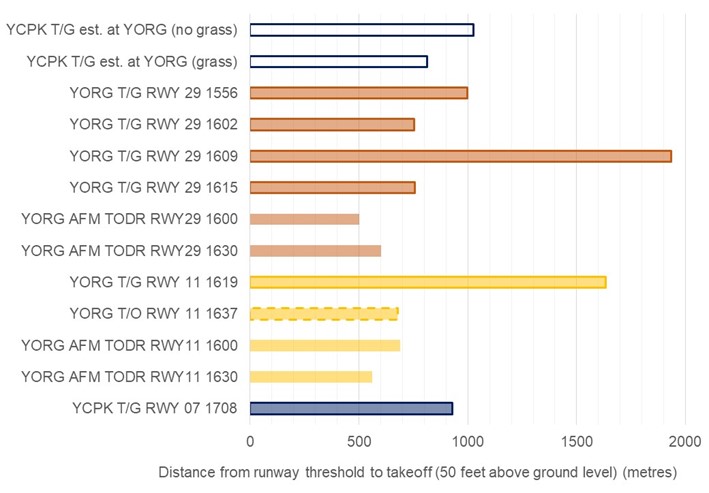
Figure 17: Distance from runway threshold to take-off for VH-OIS at Orange Airport and Coombing Park ALA, 4 Nov 2020

Source: ATSB

Comparison of Coombing Park ALA take-off position with previous touch‑and‑go runs

The measured distance between the runway threshold and take-off (the touch‑and‑go distance) at Coombing Park ALA was compared to the same distances for touch-and-goes conducted at Orange Airport. The length of the Coombing Park ALA touch-and-go was the third shortest of the flight. The two shortest touch-and-goes conducted at Orange Airport (1602 and 1615) had a length of just over 750 m. With the fourth shortest touch‑and‑go being the first approach conducted at Orange Airport (1556) at about 1,000 m.

Corrections for aircraft mass, density altitude and surface type were applied to the measured touch-and-go distance at Coombing Park to compare the length of the touch‑and‑go conducted at Coombing Park with those conducted at Orange Airport, as shown by the open blue bars in Figure 17. No correction was performed for wind to show potential variation from this as a factor. These corrections were performed as follows. The take-off distance required by the AFM (the AFM TODR) were calculated for Orange Airport and Coombing Park ALA based on the estimated aircraft take-off mass, pressure altitude and temperature at each location. The ratio between the AFM TODR between Orange Airport and Coombing Park ALA was calculated, and this was multiplied with the actual touch‑and‑go distance at Coombing Park, measured from OIS flight data, and is summarised by the following equation.
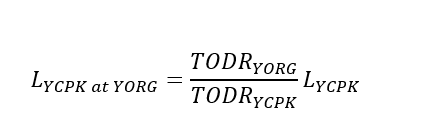
Formula

Where, LYCPK at YORG represents the estimated length of the Coombing Park ALA touch‑and‑go if it was conducted at Orange Airport. TODRYORG and TODRYCPK represent the take-off distances required for Orange Airport for reported conditions at 1600, and Coombing Park at 1700 respectively. Finally, LCPK represents the actual touch‑and‑go distance at Coombing Park measured from OIS flight data. The results of this calculation are shown by the ‘YCPK T/G est. at YORG (no grass)’ bar in Figure 17. In addition to this calculation, a correction for the grass runway was applied by multiplying TODRYCPK by 1.25, as recommended for a dry grass runway in the AFM for OIS and shown by the ‘YCPK T/G est. at YORG (grass)’ bar in Figure 17.

The estimated equivalent length of the touch‑and‑go conducted at Coombing Park ALA to Orange Airport accounting for grass was 812 m, about 8% longer than the shortest touch‑and‑go at Orange Airport. Without accounting for grass, the Coombing Park ALA touch‑and‑go projection was about 260 m longer than the shortest touch‑and‑go at Orange Airport, and marginally longer (about 15 metres) than the first touch‑and‑go conducted at 1556. The surface at Coombing Park appeared in good condition at the time of the accident, with the surface being firm, the grass relatively short, and the conditions dry. It is expected that the grass correction factor is an upper limit for the calculation of the potential length, with the lower limit being the calculation without accounting for grass.

The touch-and-go approaches at 1609 and 1619 had lift-off points considerably further along the runway than the other runs and were consistent with flight assessment exercises being conducted. The altitude profile of the 1609 touch‑and‑go was consistent with a go-around followed by a second, later touch-down, possibly simulating an early upwind engine failure. The touch‑and‑go at 1619 was likely following a practiced glide approach onto the reciprocal runway 11. These exercises were expected elements to assess the suitability to conduct a CPL flight test.

As no wind correction was applied to the estimated projection of the Coombing Park ALA touch‑and‑go length to Orange Airport, this calculation reflects the wind speed and direction as applicable at Coombing Park ALA during the touch‑and‑go at 1708. The Bureau of Meteorology identified that there was unlikely to be a headwind component during the touch‑and‑go at Coombing Park ALA. Further, based on the reported wind conditions at 1600, it is likely that a headwind component of approximately 6 kt was present at about the time of the shortest touch‑and‑go at 1602 at Orange Airport. In addition, the touch‑and‑go at 1556 likely used more runway than the Coombing Park ALA touch‑and‑go if this was conducted at Orange Airport, despite the likelihood of a 6 kt headwind component at Orange Airport during this touch‑and‑go. Therefore, a weaker headwind component is expected to have contributed to a longer landing at Coombing Park ALA than the shortest touch‑and‑goes conducted. However, based on the uncertainty in the meteorological data, and the ground speed of OIS from flight data being close to the published short field approach speed, it was not possible to determine the precise impact of wind on the touch‑and‑go distance at Coombing Park ALA.

In summary, compared to the length of the touch‑and‑goes conducted at Orange Airport, the Coombing Park ALA touch‑and‑go was the third shortest of the flight. The touch‑and‑go at Coombing Park ALA was the third shortest touch-and-go of the flight with and without density altitude corrections. Although the precise impact of the grass surface could not be determined, it is expected that this would have had the effect of reducing the projected length toward the two shortest touch‑and‑goes. Additionally, the touch‑and‑go conducted at Orange Airport at 1556 likely used more runway than an equivalent length touch‑and‑go conducted at Coombing Park at 1708, despite the 1556 touch‑and‑go likely having a larger headwind component. Based on analysis of the flight data for OIS, it appears likely that the touch down length was within the normal variability of touch-and-goes conducted by the student. Therefore, the above suggests that the length of the touch-and-go conducted by the student at Coombing Park ALA was typical of touch-and-goes conducted at Orange Airport earlier in the flight.

Estimation of standing take-off distances

The ATSB conducted an analysis examining the potential effect from performing a standing take‑off instead of the touch‑and‑go at Coombing Park ALA under the same conditions. The purpose was to estimate the maximum distance where OIS would have lifted-off along the runway at Coombing Park ALA if a standing take-off was conducted using two independent methods. One method (the ratio method) to estimate this distance was similar to the projection of the Coombing Park ALA touch-and-go to Orange Airport described above. For this method, the ratio between the standing take-off at 1637 and the measured touch‑and‑go distance was calculated, and this result was multiplied by the length of the Coombing Park ALA touch-and-go distance (929 metres). The other method was estimated standing take-off distance based on the AFM. Results from both methods are shown in Table 2.

Table 2: Standing take-off distance estimations for OIS at Coombing Park ALA runway 07

Description of standing take-off estimationMethodTake-off distance (m)
Estimation based on YORG touch and go at 1556Ratio836
Estimation based on YORG touch and go at 1602Ratio630
Take-off distance required – Nil wind factored by 25% for grassAFM675
Take-off distance required – 5 kt tailwind factored by 25% for grassAFM825

The ratio of the shortest touch‑and‑go at 1602 at Orange Airport was calculated as 0.90, equating to the longest estimated standing take-off length of 836 m. The same was performed for the 1556 touch‑and‑go, with a ratio of 0.68, and representing an upper limit of the normal touch‑and‑goes conducted. This equated to the shortest estimated standing take-off at 630 m. Standing take-off estimates based on the take-off distance required from the AFM for OIS were between the ratio‑based estimates. These were both factored by 25% to account for the short-dry grass runway for no wind, and a 5 kt tailwind.

The headwind component of the 1556 and 1602 touch‑and‑goes on runway 29 (about 6 kt) was likely greater than the headwind component of the standing take-off on runway 11 (about 1 kt), based on the reported wind conditions in METARs at 1600 and 1630. A greater headwind component would have allowed OIS to become airborne in a shorter distance with all other conditions the same. Given these conditions, the actual ratio between the standing take-off length and minimum touch-and-go length is expected to be slightly lower, making the estimated standing take-off distances slightly shorter. This indicates that the difference between the standing take-off and touch-and-goes using the ratio method is expected to be larger, and is therefore conservative.

In summary, the standing take-off length at Coombing Park ALA was estimated to be between 630 and 836 m, notably shorter than the actual Coombing Park ALA touch‑and‑go length of 929 m.

Initial climb projections

The ATSB evaluated the potential influence of a standing take-off on the height of OIS during the initial climb. This analysis used the estimated standing take-off distances described in the section above and is illustrated in Figure 18. The vertical axis shows the height above the estimated point of lift off and the horizontal axis shows the distance from the start of runway 07 at Coombing Park ALA, and also corresponds to the markers shown in Figure 6. Terrain elevation is shown by the solid dark green area, with typical tree heights indicated by the translucent dark green (minimum 10m) and light green (maximum 20m) areas.

Figure 18: Height of initial climb profile for OIS at Coombing Park ALA, including estimations for climb profiles following standing take-off and estimated terrain profile
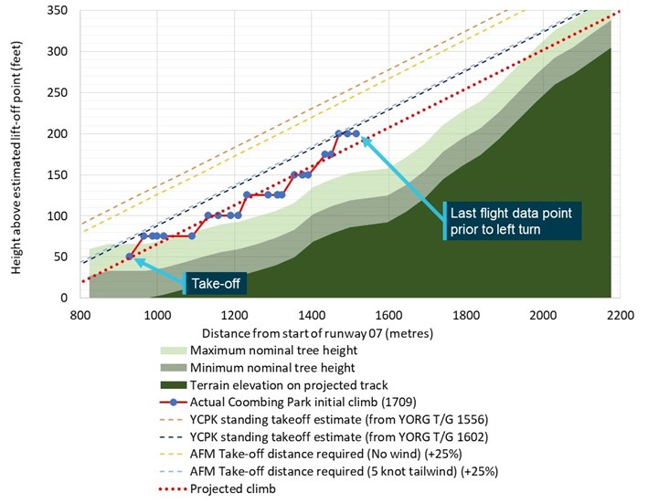
Figure 18: Height of initial climb profile for OIS at Coombing Park ALA, including estimations for climb profiles following standing take-off and estimated terrain profile

Figure showing plot of height vs distance travelled of OIS during the initial climb from Coombing Park ALA runway 07 compared to terrain and estimates for climb if a standing take-off was conducted.

Source: ATSB

The actual initial climb profile of OIS conducted at Coombing Park ALA at 1709 is shown in Figure 18 by the series with red lines and blue circles. The last data point of this series indicates the relative height of OIS immediately prior to the left turn. The red dotted series is the line of best fit for the 1709 initial climb and shows an estimated projection of the climb if the climb rate was maintained and OIS tracked in a straight line instead of turning left. The top right corner of Figure 18 shows the projected climb above the minimum nominal tree height but intercepting below the maximum nominal height.

Theoretical climb profiles representing each of the estimated standing take-off lengths shown in Table 2 are shown by the dashed light blue, dark blue, yellow, and orange lines. These were formed by translating the actual climb profile horizontally (indicated by the red-dotted line) to commence from each calculated standing take-off distance along runway 07.

The orange dashed line in Figure 18, labelled ‘YCPK standing take-off estimate (from YORG T/G 1556)’, shows the best-case estimate for a climb profile following a standing take-off at Coombing Park ALA, based on the estimated standing take-off length of 630 m. This estimate translated to be an estimated 70 ft higher than the climb following the actual touch-and-go at Coombing 1709 initial climb at each point in the climb. This was based on the mean difference between the intercepts from the equations of these lines shown in Figure 18. Similarly, the height of the worst‑case estimated standing take-off (836 m) was estimated to be 22 ft higher than the climb following the actual touch-and-go at Coombing Park ALA (shown by the dark blue dashed line in Figure 18). This represents the lower limit of the height difference. The climb profiles for the AFM-based standing take-off estimates listed in Table 2 are shown by the yellow and light blue dashed lines in Figure 18, between the other projections.

In summary, the vertical height difference between a standing take-off climb profile and the touch‑and-go climb profile was estimated by the ATSB. This was based on calculating the vertical difference between the actual climb profile following the touch-and-go at Coombing Park ALA, and theoretical climbs originating from the estimated location of standing take-offs. The analysis found that if a standing take-off was conducted at Coombing Park ALA, the height at each point during the initial climb would have likely been between 22 and 70 ft higher than the actual touch-and-go conducted by the student. The top right corner of Figure 18 shows all climbs following hypothetical standing take-offs as passing close to, but above the maximum nominal tree height at the local terrain peak.

Conclusion

Based on analysis of the flight data for OIS, the ATSB found that the length of the touch-and-go conducted by the student at Coombing Park ALA was typical of touch-and-goes conducted at Orange Airport earlier in the flight. The length of all touch-and-goes during the flight were notably longer than the standing take-off conducted at Orange Airport when corrected for density altitude (when the length was measured from the runway threshold to the point of take-off). These touch‑and-goes were also all longer than calculations using the aircraft flight manual for the accident aircraft (VH-OIS). When corrected for density altitude, a standing take-off length at Coombing Park ALA was estimated by the ATSB to be between 630 and 836 m for the atmospheric and weather conditions at the time of the accident, notably shorter than the actual Coombing Park ALA touch‑and‑go length of 929 m. This equated to OIS being between 22‑70 ft higher at each point during the initial climb if a standing take-off was conducted instead of a touch-and-go. In contrast to the initial climb after the actual touch-and-go projecting below the maximum tree height, climb projections from standing take-off estimates indicated that OIS as passing close to, but slightly above the maximum nominal tree height.

Purpose of safety investigations

The objective of a safety investigation is to enhance transport safety. This is done through:

  • identifying safety issues and facilitating safety action to address those issues
  • providing information about occurrences and their associated safety factors to facilitate learning within the transport industry.

It is not a function of the ATSB to apportion blame or provide a means for determining liability. At the same time, an investigation report must include factual material of sufficient weight to support the analysis and findings. At all times the ATSB endeavours to balance the use of material that could imply adverse comment with the need to properly explain what happened, and why, in a fair and unbiased manner. The ATSB does not investigate for the purpose of taking administrative, regulatory or criminal action.

Terminology

An explanation of terminology used in ATSB investigation reports is available here. This includes terms such as occurrence, contributing factor, other factor that increased risk, and safety issue.

Publishing information 

Released in accordance with section 25 of the Transport Safety Investigation Act 2003

Published by: Australian Transport Safety Bureau

© Commonwealth of Australia 2023

image_5.png

Ownership of intellectual property rights in this publication

Unless otherwise noted, copyright (and any other intellectual property rights, if any) in this report publication is owned by the Commonwealth of Australia.

Creative Commons licence

With the exception of the Coat of Arms, ATSB logo, and photos and graphics in which a third party holds copyright, this publication is licensed under a Creative Commons Attribution 3.0 Australia licence.

Creative Commons Attribution 3.0 Australia Licence is a standard form licence agreement that allows you to copy, distribute, transmit and adapt this publication provided that you attribute the work.

The ATSB’s preference is that you attribute this publication (and any material sourced from it) using the following wording: Source: Australian Transport Safety Bureau

Copyright in material obtained from other agencies, private individuals or organisations, belongs to those agencies, individuals or organisations. Where you wish to use their material, you will need to contact them directly.

[1]     The primary source of flight data for this investigation was from ADS-B data transmitted by OIS, retrieved from space‑based ADS-B receivers operated by Aireon located on the Iridium satellite constellation.

[2]     A high power run-up check is carried out in a piston-engine aircraft to check the aircraft’s ignition and other systems before commencing an initial take off.

[3]     The term ‘pilots’ is used throughout this report to refer to one or both pilots flying the aircraft. There was no way to determine which pilot was flying the aircraft at any time during the flight.

[4]     A climbing departure away from the airport in the same direction as the runway used for take-off.

[5]     Closed pattern, usually circular or racetrack, followed repeatedly by aircraft.

[6]     Uncertainty phase (INCERFA): an emergency phase declared by the air traffic services when uncertainty exists as to the safety of an aircraft and its occupants.

[7]     A GAF provides a pictorial representation of forecast weather conditions and is designed primarily to meet the needs of pilots flying in the airspace between the surface and 10,000 ft (AMSL).

[8]     A METAR is a routine report of meteorological conditions at an aerodrome.

[9]     QNH: the altimeter barometric pressure subscale setting used to indicate the height above mean sea level.

[10]    Ceiling and visibility okay (CAVOK): visibility, cloud and present weather are better than prescribed conditions. For an aerodrome weather report, those conditions are visibility 10 km or more, no significant cloud below 5,000 ft, no cumulonimbus cloud and no other significant weather.

[11]    The ATSB uses IPCC definitions to communicate uncertainty regarding technical information. The 67% threshold is used by the ATSB to describe where the data likely lies, and 90% to describe where the data very likely lies. This is documented in ATSB report AR-2007-053.

[12]    Australian Transport Safety Bureau (2008). AR-2007-053 Analysis, Causality and Proof in Safety Investigations, Canberra, Australia. This can be found on the ATSB’s website www.atsb.gov.au.

[13]    Uncertainty data were generated from 67th (boxes) and 90th (whiskers) percentile confidence intervals of Student’s t-distribution derived from the standard error between the flight data and the mean climb rate.

[14]    CASA Advisory Circular AC 91-02 v1.1 dated November 2021

[15]    Aeroplane Flight Instructor Manual, Civil Aviation Safety Authority, Issue 2: December 2006.

[16]    Vendeth, S (2003). A Pilot’s Guide to Safe Flying, A Manual for General Aviation Pilots (First Edition),  Mt Eliza, Victoria, Australia

[18]    Geeting, D. & Woerner, S. (1988). Mountain flying (First edition), TAB Books Inc., Blue Ridge Summit, PA.

[19]    The haversine formula determines the great-circle distance (the shortest distance) between two points on a sphere given the longitude and latitude of each point. For the purpose of these calculations over the length of a runway, this method is suitable to estimate distance.

Occurrence summary

Investigation number AO-2020-059
Occurrence date 04/11/2020
Location 27 km south of Orange Airport
State New South Wales
Report release date 04/05/2023
Report status Final
Investigation level Defined
Investigation type Occurrence Investigation
Investigation status Completed
Mode of transport Aviation
Aviation occurrence category Collision with terrain
Occurrence class Accident
Highest injury level Fatal

Aircraft details

Manufacturer Aquila Aviation by Excellence
Model AT01
Registration VH-OIS
Serial number AT01-250
Aircraft operator Soar Aviation Aircraft Holding Pty Ltd
Sector Piston
Operation type Flying Training
Departure point Bankstown Airport, New South Wales
Destination Bankstown Airport, New South Wales
Damage Destroyed

Technical assistance to RAAus - Collision with terrain, Airborne XT-912 Tourer, recreational registration 32-6225, Gatton Airpark, Gatton, Queensland, on 17 September 2020

Summary

What happened

At about 0830 EST on 17 September 2020, an Airborne XT-912 Tourer, recreational registration 32-6225, while on approach, collided with runway 01 at the Gatton Airpark authorised landing area, Gatton, Queensland. The pilot was fatally injured and the aircraft was destroyed.

In response, Recreational Aviation Australia (RAAus) commenced an investigation into the occurrence. Due to COVID-19 travel restrictions, RAAus requested technical assistance from the Australian Transport Safety Bureau (ATSB) to document and photograph the wreckage and accident site.

To facilitate this work the ATSB has initiated an external investigation under the Transport Safety Investigation Act 2003. These tasks were completed, and the factual information was provided to RAAus on 21 September 2020.

With the completion of this work, the ATSB has concluded its involvement in the investigation of this accident. Any enquiries relating to the accident investigation should be directed to RAAus at: www.raa.asn.au.

_____________

The information contained in this update is released in accordance with section 25 of the Transport Safety Investigation Act 2003 and is derived from the initial investigation of the occurrence. Readers are cautioned that new evidence will become available as the investigation progresses that will enhance the ATSB's understanding of the accident as outlined in this update. As such, no analysis or findings are included.

Occurrence summary

Investigation number AE-2020-048
Occurrence date 17/09/2020
Location Gatton Airpark, Gatton
State Queensland
Report release date 23/09/2020
Report status Final
Investigation type External Investigation
Investigation phase Final report: Dissemination
Investigation status Completed
Mode of transport Aviation
Aviation occurrence category Collision with terrain
Occurrence class Accident
Highest injury level Fatal

Aircraft details

Manufacturer Airborne Australia
Model XT-912 Tourer
Registration 32-6225
Sector Sport and recreational
Operation type Private
Departure point Gatton Airpark, Queensland
Destination Gatton Airpark, Queensland
Damage Destroyed

Rotor drive system failure and collision with terrain involving a Robinson R22, VH-YMU, 44 km south of McArthur River Mine Airport, Northern Territory, on 16 August 2020

Final report

Report release date: 04/04/2023

Executive summary

What happened

On 16 August 2020, a Robinson R22 Beta II helicopter, registered VH-YMU, was mustering cattle on a property about 44 km south of McArthur River Mine Airport, Northern Territory. The helicopter was operated by ENJAY Services, and the pilot was the sole occupant.

While hovering at a height of about 60 ft, the helicopter experienced a sudden loss of rotor drive. The helicopter rapidly lost height and collided with terrain. The pilot sustained serious injuries and the helicopter was substantially damaged.

What the ATSB found

The ATSB found evidence of fatigue cracking in the fanwheel outer support ring and in the welded region of 2 vanes of the fanwheel assembly. These fatigue cracks probably weakened the fanwheel structure sufficiently to result in in-flight break‑up of the fanwheel.

During this investigation, it was also found that there had been other instances where cracking had been identified in the welded regions of fanwheels. However, a search of the CASA Defect Report Service for R22 and R44 models identified only a single reported occurrence in 2013 for vane weld cracking.

The imbalance caused by the fanwheel break-up, likely led to the forward drive belt migrating from the drive sheaves. The remaining rear drive belt likely failed under the load exerted on it, when the helicopter impacted the ground, and the downward motion of the engine overloaded the drive belt to failure.

Due to the helicopter being in a 60 ft hover at the time of the drive belt failure, the pilot had limited options to respond to the emergency, resulting in a heavy landing and serious injuries to the pilot.

It was also identified that the details for the emergency locator transmitter had not been updated after the helicopter had been recently purchased by the operator. This led to a delay in the Joint Rescue Coordination Centre (JRCC) being able to confirm the accident. Fortunately, prompt assistance was provided to the pilot by other personnel involved in the muster.

Safety message

Cracking of Robinson fanwheels in the vane weldment, has been identified to occur in a limited number of the R22 fleet, however this was the first instance where the cracking had progressed sufficiently to permit an in-flight failure to occur. The circumstances of this accident are an important reminder for pilots and maintainers to pay particular attention to the installation, maintenance, and ongoing inspection of critical components of the Robinson R22 (and R44 – being a similar system) helicopter drive system.

The non-reporting of defects prevents the sharing of knowledge to the wider aviation community and identification of emerging issues. Defect reporting allows CASA to create a database, which is used to identify trends in design and maintenance reliability of aircraft systems and components and is a publicly accessible service. Defect reporting benefits the aviation industry such that data may be utilised to develop or review an Airworthiness Directive or Airworthiness Bulletin, which leads to long term improvement in design, manufacturing, and maintenance standards.


The investigation

Decisions regarding whether to conduct an investigation, and the scope of an investigation, are based on many factors, including the level of safety benefit likely to be obtained from an investigation. For this occurrence, a limited-scope investigation was conducted in order to produce a short investigation report and allow for greater industry awareness of findings that affect safety and potential learning opportunities.

The occurrence

On 16 August 2020, a Robinson R22 Beta II helicopter, registered VH-YMU (YMU) and operated by ENJAY Services, was being utilised for cattle mustering operations on McArthur River Station, about 44 km south‑west of the McArthur River Mine Airport, Northern Territory. At about 0700 local time, the pilot departed to begin the mustering operation. At about 0730, another pilot operating a Robinson R44 joined the mustering activities. Both then worked together to move the cattle into the yards.

Sometime later, both helicopters flew to a fuel point. A hot fuel[1] was performed to quickly return to the cattle. The R44 pilot assisted the other pilot by refuelling YMU. During the refuel, the R44 pilot reportedly noticed a drive belt misalignment on YMU. During a discussion, the pilot of YMU commented that drive belt engagement[2] on previous starts had been normal and that the clutch warning light in the cockpit had not flickered[3] during the previous flight. Both pilots considered that the misalignment did not warrant shutting down the helicopter for further investigation and decided to complete an inspection of the drive system at the conclusion of the day’s mustering.

Both helicopters returned to the mustering task and at about 1140, YMU was moving cattle toward the stockyard at low level in a valley. The pilot of the R44 was manoeuvring about 100 ft higher and about 200 m away to the left of YMU, looking for other cattle and observing YMU muster the cattle.

While YMU was being hovered at about 60 ft above ground level, the R44 pilot saw a large plume of blue smoke at the rear of YMU and, recognising a problem, quickly alerted the pilot of YMU by radio. The R44 pilot then observed fragments burst from the cooling shroud area at the rear of the helicopter before YMU rapidly descended and impacted terrain (Figure 1 and Figure 2).

Figure 1: Damage to cooling fanwheel and missing shroud

Figure 1: Damage to cooling fanwheel and missing shroud

Source: ATSB and Operator, annotated by the ATSB

The pilot of YMU reported hearing a loud bang and loss of main rotor drive propulsion and recalled that there was limited time to react due to the low-level operations at the time. The pilot sustained serious back injuries and was heavily winded from the impact, however, was able to exit the helicopter unassisted. A station hand mustering on the ground, witnessed the accident and rendered first aid to the pilot.

Figure 2: VH-YMU accident site

Figure 2: VH-YMU accident site

Source: Operator

Following the accident, the R44 pilot immediately diverted to pick up the station manager who was a short distance from the accident site, but unaware of the accident as they were on the other side of a hill with the main cattle herd. The R44 pilot returned to the accident site with the manager and first aid equipment. The pilot of YMU was transported in the R44 to the McArthur River Mine medical facility, and subsequently evacuated by aeroplane to Darwin.

The emergency locator transmitter activated during impact. The signal was detected by the Joint Rescue Coordination Centre (JRCC) in Canberra at 1209 Eastern Standard Time,[4] who then contacted the registered owner. However, due to a change of ownership, the registration details of YMU were not updated, which led to a delay in the accident confirmation and rescue effort by the JRCC.

Context

Pilot information

The pilot of VH-YMU (YMU) held a valid Commercial Pilot Licence (Helicopter) issued in May 2019, and a current Class 1 Aviation Medical Certificate. They held approvals for low-level operations and mustering and had about 300 hours flight time in helicopter mustering operations. They had worked for the operator for about 18 months.

Helicopter information

The Robinson R22 (R22) is a 2‑seat, single‑engine helicopter predominately used for pilot training, private use and in utility roles. It is primarily all‑metal construction with a 2-blade main and tail rotor system and is powered by a 4-cylinder Lycoming piston engine. YMU was manufactured in the United States in 2012 and registered in Australia in the same year. YMU changed ownership in February 2020, when it was acquired by the operator.

A routine 100-hour service was conducted about 42 hours prior to the accident, on 13 July 2020. Additional work also performed, included an adjustment of the engine height and sheave alignment. This involved shimming the engine due to engine mounts sagging. The shimming procedure raised the engine to obtain optimal alignment in the sheaves. The rotor drive belts were last replaced at 2,850.2 hours, about 275 hours prior to the accident. The maintenance release indicated that YMU had accumulated 3,125.2 hours in service on the morning of the accident.

Rotor drive system

The rotor drive system on the R22 helicopter uses two reinforced rubber drive belts. The drive belts are double-banded and fitted to multi-grooved sheaves. The upper sheave is mounted on a free‑wheel clutch shaft that drives the main rotor gearbox and the tail rotor driveshaft. The lower sheave is attached directly to the engine crankshaft.

The upper sheave is moved relative to the lower sheave by means of an electric clutch actuator, thereby controlling the tension on the drive belts. This allows the engine to be started unloaded (drive belts slack) without the drag of the rotor system, and then tensioned to allow engine power to be transmitted to the rotor drive (Figure 3).

Figure 3: Diagram of the Robinson R22 rotor drive system

Figure 3: Diagram of the Robinson R22 rotor drive system

Source: Robinson Helicopter Company, annotated by the ATSB

Robinson Helicopter Company (RHC) stated in the pilot’s operating handbook that, after engaging the clutch actuator switch, the rotors should be turning within 5 seconds. RHC Safety Notice SN‑33 also stated that if the rotors turned during the start sequence, or the time was greater than 5 seconds, it indicated that the rotor drive belts adjustment was not correct. In both scenarios, maintenance action was required to rectify the problem.

The actuator may also operate momentarily during flight as the drive belts warm up or stretch slightly. A warning light illuminates on the instrument panel to indicate any movement of the actuator and a flicker of the light during operation is considered normal. On the day of the accident, the pilot did not recall any abnormal actuator operation for the engagement of the drive belts or of a light illuminating prior to the accident.

Fanwheel

The fanwheel utilised on the R22 is a commercial product, modified by RHC. Its purpose is to direct cooling air onto the engine. The fanwheel is constructed of steel, comprising 8 cooling vanes which are welded to the rear plate (on the engine side) and a support ring at the outer side. The assembly mounts onto the fan shaft, aft of the lower sheave, and is enclosed in a fibreglass cooling shroud.

There have been several reported cases of fanwheel cracking at the bolt holes at the central hub attaching hardware on the rear plate. The fanwheel on YMU did not have any evidence of cracking from these locations. A search of the CASA Defect Reporting Service did not reveal any reports of fatigue cracking or structural failures from the vane welds of Robinson R22 (or R44) fanwheels, despite evidence of several other fanwheels being removed from service due to cracking in the welded areas. Photos of these fanwheels were provided to the ATSB during this investigation. The manufacturer also stated that fanwheels containing cracks in the vane welds had been returned to the factory.

Although there was knowledge in the Robinson community (from maintainers and operators) that cracking does occur in the welded regions of fanwheel vanes, there has been no defect reports submitted to CASA which would raise awareness of this issue. Defect reporting is an essential of aircraft operation and maintenance and the requirement is covered in Part 4B of the Civil Aviation Regulations and Advisory Circular AC 20-06v1.1.

Robinson reported to the ATSB that about 2% of R22 (and 3% of R44) fanwheels returned to Robinson fail inspection due to fatigue cracking at the vane welds. These fanwheels are removed from service and scrapped. The rejected fanwheels were identified by Robinson as having been in service for at least 2 overhauls (at least 4,400 hours, time in service).

Robinson have changed the maintenance manual requirement, which now states that fanwheels are to be replaced at the 2,200-hour inspection.[5] These are supplied as a new or factory overhauled item and are part of the 2,200-hour overhaul kit supplied by Robinson. The fanwheel that was installed on YMU had been replaced at the 2,200-hour inspection and had accumulated about 1,000 hours since installation.

The R22 maintenance manual states that a dynamic balance must be performed each time the fanwheel is fitted to the helicopter. This ensures the balance is maintained within acceptable limits to prevent damage to the fanwheel and the helicopter drivetrain. The most recent fanwheel balance on YMU had been carried out 204.5 hours prior to the accident.

Sheave alignment

In accordance with RHC maintenance requirements, sheave alignment was to be checked each 100 flight hours or 12-month period, and any time that the drive belts were replaced. The specific procedures were outlined in the R22 maintenance manual. The engine height, clutch shaft angle and throttle correlation rigging was also checked to ensure all elements of the drive system were in alignment. RHC released Service Letter SL-35 in 1990 highlighting the importance of ensuring that sheave alignment is maintained within acceptable limits. This was released to highlight the correct tooling and procedure to be used when carrying out sheave alignment.   

The Civil Aviation Safety Authority (CASA) released Airworthiness Bulletin AWB 63-006 in 2009, which emphasised the need to adhere to all current RHC data. It noted that engine height and sheave alignment was a critical element of the drive system. RHC testing identified that most drive belt failures are caused by misalignment of the drive belts on the sheaves.

Damage to the helicopter

A post-accident inspection of the helicopter was completed by the operator and the R44 pilot at the accident site the following day. The operator reported that the:

  • forward drive belt was displaced forward from its normal operating position on the sheaves, and was tangled around the lower sheave and ring gear, and the upper sheave on the clutch shaft
  • rear drive belt had split and was laying on the ground under the helicopter
  • clutch actuator and engine cooling shroud had broken free from the rear of the engine
  • tail rotor control bell crank had fractured, and a segment was in the tail boom
  • metal cooling fanwheel was damaged, with 2 vane segments found away from the main wreckage.

Additionally, the skid landing gear was splayed outward, and the pilot seat base had collapsed mainly on the right rear side. The forward tail rotor drive flex coupling was significantly damaged, most likely due to contact from the failing fanwheel or the tail cone attachment lower frame. The tail rotor blades had fractured, and the lower vertical stabiliser was bent to the left. Both main rotor blades had minor impact damage, most likely due to contact with the surrounding trees.

Operator-supplied images of the collapsed pilot seat structure of YMU also showed several items stored under the seat. While not evident that the equipment had filled the area, large amounts of equipment stored under the seat can lead to occupant injuries in the event of an accident, as the collapsible space may be compromised. In the case of this accident, there was sufficient collapsible space to prevent further injury to the pilot during the impact sequence.

Component examination

The drive belt set, fanwheel, tail rotor blades, clutch actuator and drive sheaves were examined at the ATSB’s technical facilities in Canberra (Appendix). The ATSB’s examination found that the forward drive belt had disengaged and become entangled in the rotating drive train components and the rear drive belt had stretched before failing in overload. The upper and lower sheaves had significant rubber deposits on the forward surfaces due to drive belt skidding. No indication of abnormal wear or damage was identified on the painted surfaces within the sheave grooves from a drive belt anomaly.

Measurements showed that the clutch actuator had not extended to is full travel limit. Additionally, the actuator had sustained impact damage and had fractured in overstress from its mount location.

The metallurgical examination of the fanwheel identified evidence of pre-existing fatigue cracks in the welded region of 2 vanes, and in the outer support ring structure. Two segments of fanwheel had liberated from the assembly. One segment had 1 vane with evidence of severe metal-to-metal contact during the rotation of the fanwheel, and a black witness mark, which was most likely rubber transfer due to contact with the drive belt/s. The other was a segment of 2 vanes with wood fibres entrapped in the structure.

The fibreglass cooling shroud showed evidence of slice and penetration damage and had been separated from the rear of the engine in flight. This damage was most likely a result of fanwheel segments separating from the cooling fan while the fanwheel was rotating.

Both tail rotor blades had fractured at the root with evidence of rotation at the time of impact.

Emergency locator transmitter

The helicopter was equipped with a Kannard 406 AF emergency locator transmitter (ELT). Impact forces automatically activated the ELT, which then transmitted a signal on the 406 MHz frequency. This transmission contains digital information, including a unique identifier, enabling the search and rescue authority to contact the registered owner of the beacon to determine whether the activation was a false alarm or genuine. At the time of writing, the 406 MHz ELT was required to be registered with the Australian Maritime Safety Authority.

The signal relating to this accident was received by the Joint Rescue Coordination Centre (JRCC) in Canberra, who then attempted to contact the registered owner. They advised that the aircraft had been sold and that the details had not been updated since the change of ownership in February 2020. After being provided contact details for the new owner, JRCC then attempted unsuccessfully to contact them. As such, the JRCC was unable to confirm the validity of the ELT activation.

JRCC then contacted the Northern Territory Police. The police point of contact in the area was, coincidentally, the R44 pilot who was able to confirm the accident occurrence to the police about one hour after the ELT was first detected. The aircraft operator switched the ELT off on the following day when they attended the site. While not affecting the response to this accident, more generally it is important that contact details of the registered owner are up to date to ensure a timely search and rescue.

Low-level operations

A successful forced landing following a complete drive train failure requires a sufficient combination of height (potential energy) and airspeed (kinetic energy). A description of sufficient available energy following a sudden loss of power is provided in the height/velocity (H/V) diagram (Figure 4). While most mustering operations take place at a height and airspeed suitable for forced landings, there is occasional need to operate within the shaded avoid area of the H/V diagram.

When operating within the shaded area, pilots are exposed to the risk of a high energy impact in the event of a sudden loss of power to the rotor system. However, in practice this risk must be balanced with other risks associated with low‑level operation such as obstacle collision (e.g., trees and wires) and brown out from dust. There is also the consideration of being able to complete a task efficiently. At the time of rotor drive belt failure, the pilot of VH-YMU was operating inside the avoid area of the H/V diagram.

Figure 4: Robinson R22 height/velocity diagram

Figure 4: Robinson R22 height/velocity diagram

Source: Robinson Helicopter Company (annotated by the ATSB)

Hot fuelling

While there was no procedure for hot fuelling in the operators Operations Manual as required in Civil Aviation Order 20.10[6] (which was in force at the time of the accident), it is common in aerial mustering operations. In a single person operation, to hot fuel the aircraft, the pilot must leave the controls. This increases the risk of loss of control of the helicopter and has resulted in aircraft unintentionally becoming airborne, leading to injury of bystanders and damage to the helicopter. The Robinson R22 pilot’s operating handbook (POH) cautions against leaving flight controls unattended. Additionally, friction locks have been stated by CASA as unsuitable for use to secure unattended controls.

CAO 20.10 required hot fuelling be carried out safely and must have regard to the helicopter flight manual. Cautions written in a POH are binding requirements under Civil Aviation Safety Regulation (CASR) 138.210. This was also the case under subregulation 138 (1) of the Civil Aviation Regulations 1988. The Robinson POH caution would have prevented hot fuelling without the pilot on board the rotorcraft.

In addition, piston engine fuel possesses a higher flammability than turbine fuels, which can also contribute to a potential fire risk during hot fuelling operations, particularly when the fuel tanks are located above the engine.

Information relating to hot fuelling of an aircraft is contained in CASR 91.500 and 91.505 and the CASR Part 91 Plain English Guide. Further guidance can be found in the Visual Flight Rules Guide.

Safety analysis

Rotor drive system failure

Fanwheel failure

It could not be determined why the fanwheel assembly began to break up during the flight, mainly due to the limited amount of cracking evident within the fanwheel structure itself. The presence of fatigue cracking in the welded regions from the fanwheel vanes and on the outer support ring, were considered a pre-existing defect. There was no metallurgical evidence of continuous/intermittent crack growth from that region of damage to indicate that a period of progressive crack growth had occurred to the extent that the structural integrity of the fanwheel should have been affected.

Drive belt failure

Examination of the drive belts and photographs provided to the ATSB by the operator, established that the forward drive belt dislodged and moved forward, entangling in the rotating components of the engine and rotor drive. This was further supported by the witness account from the pilot of the R44, who observed smoke from the rear of VH-YMU moments before the accident. The forward drive belt showed signs of being heated and abraded by frictional contact with the upper sheave and clutch shaft. It is likely that the remaining rear drive belt failed in tensile overstress from the downward motion of the engine during the ground collision. This is supported by the short time from fanwheel failure to ground impact and the inability of the clutch actuator to have travelled to its full extension to cause the drive belt to fail through overstretching.

As the circumference and cross-sectional profile of the forward belt were consistent with a new Revision‑Z belt, dislodgement due to a belt defect was considered unlikely. The examination of the upper and lower sheaves showed that the sheave grooves did not exhibit any abnormal wear or damage to the painted surfaces, which also supported positive belt engagement.

Summary

The partial fragmentation of the fanwheel during flight resulted in a sudden load imbalance on the rotor drive system. Fragments from the fanwheel had evidence of contacting the rotor system drive belt/s, however it could not be determined if this affected the forward drive belt’s engagement. The more probable scenario was that the mass imbalance that resulted from the fanwheel fragmentation, probably led to the forward drive belt being disengaged from the drive sheaves. The subsequent load placed on the rear drive belt from the engine weight at ground impact likely led to it failing in overload.

Low-level operations

Mustering operations involve manoeuvring at low-level and at varying airspeeds. Such operations increase the risk associated with a loss of engine power. In this accident, the operational requirement to operate at about 60 ft above ground level did not allow sufficient time for the pilot to react to the drive belt failure or provide sufficient aircraft energy for an autorotation to cushion the landing.

The high hover provided limited opportunity to conduct a safe forced landing, however the pilot, with the remaining energy in the rotor system, was able to manoeuvre to a clear area and land the helicopter in an upright attitude, lessening the injuries sustained.

Emergency locator transmitter

Activation of the emergency locator transmitter (ELT) on impact and transmission of the 406 MHz signal was detected by the Joint Rescue Coordination Centre, although incorrect contact details delayed confirmation of the accident.

Fortunately, this accident was reacted to quickly, due to the mustering being performed by 2 helicopters operating in close proximity and nearby ground crew. In a circumstance where an aircraft may be operating alone, any delayed search and rescue (SAR) response has the potential to be a critical factor in occupant survival.

ELT registration is entered onto a database that is always accessible to SAR authorities. Up to date contact information is vital in deploying SAR resources and medical assistance effectively when an activation is detected.

Defect reporting

There is reportedly an awareness within operators of Robinson helicopters that cracking can occur at the welded regions of the cooling fanwheel, however this is not reflected in the CASA Defect Reporting Service data. Reporting of in-service defects, whether identified during operation or maintenance, must be reported to CASA via the online defect reporting service. This ensures a database can be maintained to assist in identifying reliability of aircraft components and systems which benefits the wider aviation community.

Additionally, feedback provided to the manufacturer permits awareness of defects to be identified and investigated, and system improvements to occur should it be required. This ensures that aircraft component reliability and safety are maintained at optimum levels.

Findings

ATSB investigation report findings focus on safety factors (that is, events and conditions that increase risk). Safety factors include ‘contributing factors’ and ‘other factors that increased risk’ (that is, factors that did not meet the definition of a contributing factor for this occurrence but were still considered important to include in the report for the purpose of increasing awareness and enhancing safety). In addition ‘other findings’ may be included to provide important information about topics other than safety factors. 

These findings should not be read as apportioning blame or liability to any particular organisation or individual.

From the evidence available, the following findings are made with respect to the rotor drive system failure and collision with terrain, involving a Robinson R22 Beta II, VH-YMU, 44 km south of McArthur River Mine Airport, Northern Territory on 16 August 2020.

Contributing factors

  • It is likely that fatigue cracks in the vane welds and outer support ring of the fanwheel reduced its structural integrity, leading to an in-flight fracture and release of fanwheel segments.
  • The forward drive belt migrated from the rotor system drive sheaves, probably due to the resulting drivetrain imbalance from the fanwheel failure. The loads exerted on the rear belt due to movement of the engine weight during impact likely led to its subsequent failure.
  • While operating at low-level during mustering operations, the pilot had limited opportunity to arrest the descent before impacting terrain once rotor drive was lost.

Other factors that increased risk

  • The helicopter had recently changed ownership, but the emergency locator transmitter registration had not been transferred to the new owner. This delayed confirmation of the accident by the Joint Rescue Coordination Centre.
  • The apparent non-reporting of defects associated with the cooling fanwheel increased the risk that any associated safety issue would not be identified.

Sources and submissions

Sources of information

The sources of information during the investigation included the:

  • pilot of VH-YMU
  • operator/chief pilot
  • maintenance organisation for VH-YMU
  • accident witness
  • Robinson Helicopter Company
  • Australian Maritime Safety Authority
  • Civil Aviation Safety Authority.

References

Australian Government 2013, AI-2009-038, Reliability of the Robinson R22 helicopter belt drive system, Australian Transport Safety Bureau, Canberra, ACT, viewed 8 November 2021, <Reliability of the Robinson R22 helicopter belt drive system (atsb.gov.au)>.

Australian Maritime Safety Authority [current], Beacons and MMSI Register, accessed 14 February 2023, <Public - Home - 406MHz Distress Beacon and MMSI Register (amsa.gov.au)>.

Civil Aviation Safety Authority Briefing 2020 Flight Safety Australia -The challenge for aerial mustering [Online video] Available at: https://www.youtube.com/watch?v=hiViOeqZO_o Accessed:[4 Nov 2021]

Civil Aviation Safety Authority 2015, Sector Risk Profile for the aerial mustering sector, accessed 8 November 2021, < Sector Risk Profile for the aerial mustering sector (casa.gov.au)>.

Civil Aviation Safety Authority 2021, CASR Part 91, General Operating and Flight Rules, Plain English Guide, accessed 14 February 2023. < Part 91 plain English guide version 2.0 (casa.gov.au)>.

Civil Aviation Safety Authority 2021, Part 4B of CAR Defect reporting, accessed 14 February 2023, < Part 4B of CAR Defect reporting | Civil Aviation Safety Authority (casa.gov.au)>.
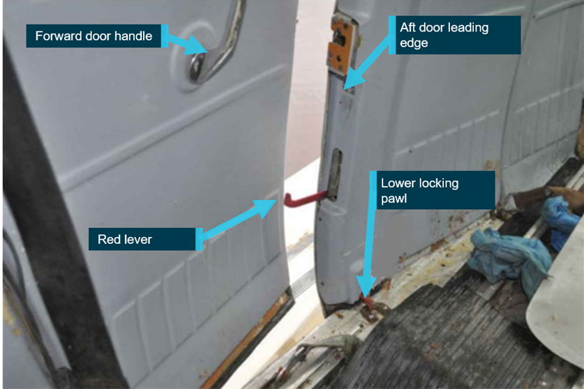
Civil Aviation Safety Authority 2022, Advisory Circular AC 20-06 v1.1, accessed 14 February 2023, < AC 20-06 v1.1 - Defect reporting (casa.gov.au)>.

Robinson Helicopter Corporation 2020, R22 Pilot’s Operating Handbook, section 4, p.4-7 and section 10, p.27.

Robinson Helicopter Corporation 2020, R22 Pilot’s Operating Handbook, section 5, p.5-11.

Robinson Helicopter Corporation 2018, R22 Maintenance Manual, chapter 7, pp.7.20-7.22.

Submissions

Under section 26 of the Transport Safety Investigation Act 2003, the ATSB may provide a draft report, on a confidential basis, to any person whom the ATSB considers appropriate. That section allows a person receiving a draft report to make submissions to the ATSB about the draft report.

An initial draft of this report was provided to the following directly involved parties:

  • the pilot of VH-YMU
  • the pilot of the R44
  • the operator
  • the maintenance provider
  • Robinson Helicopter Company
  • the Civil Aviation Safety Authority.

Submissions on that draft were received from the:

  • operator
  • maintenance provider
  • Robinson Helicopter Company
  • Civil Aviation Safety Authority.

The submissions were reviewed and resulted in significant change to the initial draft report. As such, this second draft report was provided to the above directly involved parties. Submissions on the second draft report were received from the:

  • operator
  • Robinson Helicopter Company
  • the Civil Aviation Safety Authority.

The submissions were reviewed and, where considered appropriate, the text of the report was amended accordingly.

Appendix

Component examination

The helicopter wreckage was transported to a maintenance facility where sections of the helicopter drive system were subsequently removed and sent to the ATSB’s technical facilities in Canberra for detailed examination.

Drive belts

That examination identified that the drive belts fitted to YMU were part number A190-2, Revision‑Z, and had been in service for about 275 hours. The examination and review of the on‑site imagery identified that during operation, the forward drive belt had dislodged and shifted out of position from the upper and lower sheaves.

The forward drive belt had sustained consequential damage from contact with the rotating drive system components, as evidenced by abraded rubber deposits on the forward face of the upper sheave and on the clutch shaft. Measurement of the rear drive belt identified that it had a 25 mm greater overall circumference than the forward drive belt, indicating that the rear drive belt had stretched during the ground impact and then failed in tensile overstress (Figure 5). The circumference of the forward drive belt was consistent with that of a new Revision‑Z belt and the cross-sectional profile of both belts did not show any evidence of excessive wear.

Figure 5: Drive belt damage

Figure 5: Drive belt damage

Source: ATSB

Measurement of the clutch actuator identified that it had not reached its full extension, indicating that the period from complete drive train failure to ground impact was likely to have been rapid. No abnormal wear to the paint within the sheave grooves had occurred. Some localised chipping of the aluminised coating had occurred, however that damage was likely produced during the accident sequence.

Tail rotor blades

Examination of the tail rotor blades showed that each had fractured in a uniform, almost identical manner, close to the blade attachment to the hub. Bending and deformation of the skin surfaces surrounding the fracture points was against the direction of rotation. This indicated that the tail rotor had been rotating at the time of the failure, most likely while being driven by the residual rotational force of the rotor system.

Fanwheel

Examination of the fanwheel identified that it had sustained significant disruption with 3 of the cooling vanes and associated rear support ring separated from the main structure. The liberated sections of fanwheel were comprised of a single vane ring and another comprising two vane rings. The fanwheel had sustained overall deformation, off axis bending with twisting and buckling evident throughout the structure. Notably, one of the liberated vane segments displayed considerable sliding contact damage.

The ATSBs metallurgical examination identified the presence of discrete pre-existing fatigue cracks on the fracture surfaces of the fanwheel where the cooling vanes had been welded. The formation of corrosion product on some of those crack surfaces indicated that those fatigue cracks had been present for a significant period. The fanwheel fracture surfaces, beyond the regions of fatigue, showed evidence of gross tearing that was consistent with overstress of the structure.

A detailed examination of the fanwheel fracture surfaces identified regions of fatigue cracking located on the weldment of the fan vanes. These were located at the rear of one vane (Region 5) and forward of the next vane (Region 3), where the vane was welded to the fanwheel rear plate. The fatigue cracks were measured at approximately 8 and 12 mm, respectively. The vane section containing the 12 mm crack had separated from the fanwheel along with another vane and displayed rapid ductile tensile tearing of the fracture surface (Figure 6).

Figure 6: Fanwheel fatigue cracking

Figure 6: Fanwheel fatigue cracking

Source: ATSB

The vane support ring also had an area of fatigue cracking (Region 4) measuring approximately 45 mm. There was a degree of corrosion formation on the surfaces that suggested the cracking had been there for a significant period. There was insufficient metallurgical evidence on the fracture surfaces of the vane support ring to conclude definitively whether this region was damaged by fatigue that then could have led to a structural weakening of the fanwheel.

When considering the hypothesis for an in-flight break-up of the fanwheel to have occurred, ATSB’s examination of the single vane that had released from the fanwheel showed extensive rotational contact and scoring damage from metal-to-metal contact. That damage conflicted with the metallurgical evidence and was an indicator of a potential in-flight release and subsequent contact of that part with nearby rotating drivetrain componentry.

The larger segment of the fanwheel that had also released (containing the two vanes) was extensively deformed and contained entrapped wood fibres that was consistent with that portion striking a tree. There was an absence of wood fibres on all other parts of the fanwheel. It is likely that this section of fanwheel contacted a tree after it had broken from the fanwheel, prior to ground impact (Figure 7).

Figure 7: Fragmented cooling fanwheel and liberated fragments: a vane section sustained severe metal-to-metal contact and a lager section contained entrapped wood fibres

Figure 7: Fragmented cooling fanwheel and liberated fragments: a vane section sustained severe metal-to-metal contact and a lager section contained entrapped wood fibres

Source: ATSB

Purpose of safety investigations

The objective of a safety investigation is to enhance transport safety. This is done through:

  • identifying safety issues and facilitating safety action to address those issues
  • providing information about occurrences and their associated safety factors to facilitate learning within the transport industry.

It is not a function of the ATSB to apportion blame or provide a means for determining liability. At the same time, an investigation report must include factual material of sufficient weight to support the analysis and findings. At all times the ATSB endeavours to balance the use of material that could imply adverse comment with the need to properly explain what happened, and why, in a fair and unbiased manner. The ATSB does not investigate for the purpose of taking administrative, regulatory or criminal action.

Terminology

An explanation of terminology used in ATSB investigation reports is available here. This includes terms such as occurrence, contributing factor, other factor that increased risk, and safety issue.

Publishing information 

Released in accordance with section 25 of the Transport Safety Investigation Act 2003

Published by: Australian Transport Safety Bureau

© Commonwealth of Australia 2023

image_5.png

Ownership of intellectual property rights in this publication

Unless otherwise noted, copyright (and any other intellectual property rights, if any) in this report publication is owned by the Commonwealth of Australia.

Creative Commons licence

With the exception of the Coat of Arms, ATSB logo, and photos and graphics in which a third party holds copyright, this publication is licensed under a Creative Commons Attribution 3.0 Australia licence.

Creative Commons Attribution 3.0 Australia Licence is a standard form licence agreement that allows you to copy, distribute, transmit and adapt this publication provided that you attribute the work.

The ATSB’s preference is that you attribute this publication (and any material sourced from it) using the following wording: Source: Australian Transport Safety Bureau

Copyright in material obtained from other agencies, private individuals or organisations, belongs to those agencies, individuals or organisations. Where you wish to use their material, you will need to contact them directly.

[1]     Hot fuelling means the refuelling of a helicopter with its engine or engines running.

[2]     After engagement of the clutch actuator, the pilot must ensure the rotors turn within 5 seconds, ensuring correct system adjustment and drive belt stretch is not excessive.

[3]     The presence of the clutch light flickering indicates the clutch is moving to take up drive belt looseness in operation.

[4]     Eastern Standard Time: Coordinated Universal Time (UTC) + 10 hours.

[5]     The overhaul of the complete helicopter is carried out each 2,200 hours or 12 years, time-in-service of the helicopter.

[6]     Legislation for hot fuelling changed on 2 December 2021, now covered under Civil Aviation Safety Regulation CASR 138.300.

Occurrence summary

Investigation number AO-2020-043
Occurrence date 16/08/2020
Location 44 km south of McArthur River Mine Airport
State Northern Territory
Report release date 04/04/2023
Report status Final
Investigation level Short
Investigation type Occurrence Investigation
Investigation status Completed
Mode of transport Aviation
Aviation occurrence category Collision with terrain
Occurrence class Accident
Highest injury level Serious

Aircraft details

Manufacturer Robinson Helicopter Co
Model R22 Beta
Registration VH-YMU
Serial number 4560
Aircraft operator Enjay Services Pty Ltd
Sector Helicopter
Operation type Part 138 Aerial work operations
Departure point McArthur River Station, Northern Territory
Destination McArthur River Station, Northern Territory
Damage Substantial

Accredited representative to the Papua New Guinea Accident Investigation Commission investigation into a collision with terrain, involving Cessna 402C, registered VH-TSI, near Papa Lealea, Central Province, Papua New Guinea, on 26 July 2020

Summary

On 26 July 2020, a Cessna 402C, registered VH-TSI, collided with terrain during a rejected take-off from an uncommissioned airfield near Papa-Lealea, about 16 NM north-west of Port Moresby, Papua New Guinea. The aircraft was substantially damaged and the pilot (the only occupant) sustained minor injuries.

The Papua New Guinea Accident Investigation Commission (AIC) investigated the accident. During its investigation, the AIC requested assistance from the Australian Transport Safety Bureau (ATSB).

To facilitate this work, the ATSB initiated an external investigation under the provisions of the Transport Safety Investigation Act 2003.

On 31 December 2020, the AIC released the final investigation report into this accident. Accordingly, the ATSB has concluded its involvement in the investigation.

Any enquires relating to the investigation should be directed to the Papua New Guinea Accident Investigation Commission at www.aic.gov.pg.

Occurrence summary

Investigation number AE-2020-039
Occurrence date 26/07/2020
Location Papa Lealea, Central Province, Papua New Guinea
State International
Report release date 06/01/2021
Report status Final
Investigation type External Investigation
Investigation phase Final report: Dissemination
Investigation status Completed
Mode of transport Aviation
Aviation occurrence category Collision with terrain
Occurrence class Accident

Aircraft details

Manufacturer Cessna Aircraft Company
Model 402C
Registration VH-TSI
Serial number 402C0492
Sector Piston
Operation type Unknown
Damage Substantial

Main rotor blade strike involving Leonardo Helicopters AW139, VH-EGK, 16 km west-south-west of Caboolture Airport, Queensland on 20 June 2020

Discontinuation notice

Report release date: 28/06/2024

Section 21 (2) of the Transport Safety Investigation Act 2003 (TSI Act) empowers the ATSB to discontinue an investigation into a transport safety matter at any time. Section 21 (3) of the TSI Act requires the ATSB to publish a statement setting out the reasons for discontinuing an investigation. The statement is published as a report in accordance with section 25 of the TSI Act, capturing information from the investigation up to the time of discontinuance.

Overview of the investigation

The occurrence[1]

Aeromedical tasking and flight preparation

In June 2020, the ATSB commenced a transport safety investigation into a main rotor blade strike involving a Leonardo Helicopters AW139, registered VH-EGK and operated by Queensland Government Air, about 16 km west‑south‑west of Caboolture airfield, Queensland.

On 20 June 2020, at about 1709 local time, the aircrew (comprising the pilot, aircrew officer (ACO) and rescue crew officer (RCO)) and medical crew (flight doctor and paramedic) were tasked with retrieving a patient from a property near Caboolture and transporting them to the Royal Brisbane Hospital. In preparation for the flight, the pilot completed an operational pre‑flight risk assessment, which indicated ‘normal operations’, permitting acceptance of the task without further discussions with the operator’s duty management pilots. The remaining crew refuelled the helicopter and configured the cabin for a night winch rescue.

Transit to the site

At about 1746, the helicopter departed Archerfield Airport. The flight was operated under the instrument flight rules,[2] with the aircrew using night vision goggles.[3]

On approach to the rescue site, the ACO contacted the ground paramedic to confirm the patient’s status and ascertain whether any areas nearby could be used for a landing, to avoid the requirement to winch. The ground paramedic advised that a suitable landing site was not available, but there was a possible suitable winching position about 20 m behind the ambulance. The ACO requested the ground paramedic keep the ambulance lights and roof top emergency beacon on, to assist in identification of the winch location. 

Arrival on site and insertion winches

The helicopter arrived in the vicinity of the site at about 1800 in dark conditions, approximately 30 minutes after last light.[4] The pilot and ACO identified the site, completed the pre-landing checklist, and put the ‘Trakkabeam’[5] on. The aircrew discussed the site characteristics and planned the approach. 

Recorded flight data showed that several orbits of the rescue site were conducted. During the final orbit, the pilot briefed the crew on the site. At about 1813, the pilot commenced a descent to the site and completed power checks and briefed the escape route. At about 1818, the pilot manoeuvred the helicopter to a low reference datum[6] of about 200 ft above ground level and 50 m north of the insertion winch location. From this position, the aircrew conducted the reconnaissance brief. They checked the power setting, radio altitude reading, security of harnesses, and if they had ‘good references’. The pilot then handed the conning[7] over to the ACO. 

Between about 1821 and 1826, the crew completed 2 insertion winches to lower the RCO, flight paramedic and stretcher, from a height between 65–100 ft. The helicopter then departed the site to the east and orbited for about 20 minutes while the patient was prepared for extraction. During this time, the pilot and ACO commented on the rain passing through the area and prepared for the extraction winches. 

The extraction winch and collision with terrain

The patient was moved from the side of the hill to a position in an open area considered suitable for winching. At about 1841, the RCO radioed the ACO to report that they were ready for the winch. The pilot verbalised to the ACO ‘same brief as before’, which was acknowledged by the ACO. The pilot and ACO both reported there was no re-identification, verbalisation or re-briefing of the critical hazards (outlying trees) associated with the revised extraction winch position. They then completed their final checks. At about 1846, the helicopter was established in a hover about 80 ft directly above the patient. At interview, the pilot approximated the helicopter’s main rotor was rotating about 1 m from the surrounding tree line.

The flight paramedic and the patient on a stretcher were winched into the helicopter. As the winch was lowered to collect the RCO, the ACO directed the pilot to move forward and right, twice. As the RCO was about to be winched, they verbalised for the ACO to hold them on the ground as they had momentarily lost their night vision goggles mount. At about 1851, the ACO confirmed to the pilot that they were holding a good position. The recorded data showed that, over the last minute, the helicopter’s height ranged between about 50–65 ft above the ground (861–876 ft above mean sea level) and the heading changed between about 111–120°.

Shortly after, the doctor called out ‘trees, trees’, at which point the helicopter’s main rotor blades contacted a tree. Immediately following the main rotor strike, the ground paramedic reported seeing a branch fall through the trees, with an estimated diameter of 10 cm and length of about 1‍–‍1.5 m.

Recovery and return to Archerfield

In response, the pilot immediately manoeuvred the helicopter away from the tree line. The RCO was subsequently raised off the ground, contacted the trees and went into a spin. Shortly after, the RCO was safely secured inside the aircraft. The pilot reported that feedback through the flight controls remained normal, with no abnormal vibrations. However, as a precaution, the pilot elected to return to the helicopter’s base at Archerfield Airport. 

Helicopter damage assessment

An engineering inspection of the main rotor blades identified damage to one of the 5 tip caps, which was missing about 50 g of honeycomb and skin material (Figure 1). Two other main rotor blades had minor abrasions to the paint layer. No other significant damage was observed.

The helicopter manufacturer considered a loss of 40–50 g on a main rotor blade tip was generally not enough to generate a perceivable vibration in the aircrew or passenger compartments. 

Figure 1: Damage to the main rotor blade tip

Figure 1: Damage to the main rotor blade tip

Source: ATSB

Environmental information

Meteorological conditions

The Bureau of Meteorology graphical area forecast applicable for the flight and occurrence location indicated the conditions were:

  • visibility was greater than 10 km, with broken[8] stratus cloud between 2,000–3,000 ft above mean sea level, and from 1900 local time, broken cumulus and stratocumulus cloud between 3,000–6,000 ft 
  • visibility reducing to 3,000 m in isolated showers of rain, with broken stratus cloud between 1,000–3,000 ft and broken cumulus cloud between 3,000–8,000ft.

Significant rainfall had been recorded in the vicinity of the site over the preceding days. Immediately prior to the occurrence, the Bureau of Meteorology weather radar indicated light rain in proximity. The pilot reported there was more weather to the west of their site and that it was clear to the east. The cloud base had reduced as they were operating, and they had passing showers, with some rain on the windscreen. Recorded audio from the helicopter captured the aircrew discussing rain while orbiting to the east before returning for the extraction winch. Mobile phone footage taken from the ground showed moderate rain during the extraction sequence. 

Lighting conditions

It was reported that there was limited ambient lighting generated from surrounding residential and farming properties. The astronomical conditions indicated very low celestial illumination in the vicinity of the site, with 1.7% moon illumination. Despite this, both the pilot and ACO reported they had good visibility, and they did not notice any scintillation[9] of their night vision goggles due to the low light. 

Investigation activities

During the investigation, the ATSB:

  • interviewed the aircrew, medical crew and relevant safety personnel
  • examined data from the helicopter’s multi-purpose flight recorder and mobile phone footage of the winching operation
  • reviewed the environmental conditions
  • reviewed the operator’s standard operating procedures
  • consulted the helicopter manufacturer
  • considered similar occurrences.

ATSB observations

Helicopter drift and visual cueing environment

Unbeknown to the pilot, the helicopter drifted during the night extraction of the RCO, resulting in the main rotor blades impacting a tree. Further, the aircrew were potentially operating in a degraded visual cueing environment due to the meteorological and lighting conditions at the time. 

Pre-flight operational risk assessment 

The operator’s pre-flight operational risk assessment tool was not accurately completed, resulting in a low-risk score that did not reflect the accurate flight conditions. Further, the tool did not consider the relative humidity when evaluating the environmental conditions, nor did it include a risk level that equated to a mandatory no-go decision.

Obstacle clearance limits

During the extraction, the helicopter was hovered closer to the surrounding tree line. It was noted that there were no minimum obstacle clearance limits prescribed by the operator, particularly for when operating in confined areas.

In-flight risk assessment

The aircrew did not fully complete the reconnaissance brief for the insertion winch sequence and therefore had not identified the closest obstacles or external hover references. 

Actions following a suspected or actual obstacle collision

As no apparent issues were identified with the helicopter following the main rotor blade strike, it was returned to the operator's base. This involved flying over a populated area, although the damage severity was unknown. The operator did not have a published procedure regarding the actions required by aircrew following a suspected or actual collision with an obstacle such as conducting a precautionary out-landing. 

Operator safety action

In response to this occurrence, the operator has implemented a range of safety actions, such as:

  • Introduced additional requirements to strengthen the operational risk assessment process. Such as, the inclusion of relative humidity (temperature dewpoint spread) in the pre-flight risk assessment operational tool, the requirement to consult with a management pilot when the risk was assessed as ‘orange – extreme caution’ or above, increased coordination with the tasking agency regarding the acceptance of the rescue task, and the recording and auditing of risk assessment scores. Similarly, an instruction was issued to aircrew emphasising that the risks associated with winching operations should be assessed at tasking, dispatch, arrival on site, and throughout the operation.
  • Released a standards directive and updated the aircrew operations manual with additional obstacle clearance requirements. This included mandatory minimum distances from obstacles when operating in, or within the vicinity of a confined area, or manoeuvring near obstacles.
  • Released a standards directive and updated the aircrew operations manual requiring the pilot in command to land as soon as possible when either ‘suspecting or observing’ helicopter damage. 

Safety message

The flight planning and task preparation stage provides an important opportunity to assess the operational environment prior to task acceptance and departure. Risk management strategies such as a pre-flight risk assessment tool can help pilots apply a systematic process to decision‑making and assist with mitigating other hazards that could adversely affect the safety of flight. 

However, as a pre-flight risk assessment tool cannot anticipate all hazards and corresponding risks that may emerge during the flight, aircrew should continually reassess the operational risk to determine if the applied risk controls are appropriate or require adjustment to ensure flight safety is maintained. In-flight briefings are an effective mechanism for achieving this. Likewise, such briefings aid an aircrew’s shared understanding of how the tasking is to be completed. This understanding is then reinforced through positive communications between the aircrew throughout the tasking.

Finally, this occurrence illustrates the importance of an appropriate response if a helicopter is suspected of colliding with terrain, regardless of the presumed severity. Unknown damage to a helicopter’s main or tail rotor system could quickly develop into a much more serious situation, particularly when operating over a densely populated area.

Reasons for the discontinuation

Based on a review of the available evidence, the ATSB considered it was unlikely that additional investigation would identify further important safety lessons. Queensland Government Air has been briefed about the ATSB’s observations and potential learnings. While the broader communication of this information is useful to other similar operators, in this case, appropriate safety action has been taken by Queensland Government Air. 

The evidence collected during this investigation remains available to be used in future investigations or safety studies. The ATSB will also monitor for any similar occurrences that may indicate a need to undertake a further safety investigation. Consequently, the ATSB has discontinued this investigation. 

[1]     The ATSB’s preliminary report into the occurrence was published on 12 August 2020 based on an initial review of the evidence available at that time. Discrepancies with some of the details contained within that report have since been identified. The preliminary report remains on file but has been removed from the website. The discontinuation notice addresses the relevant factual information for the occurrence, verified up to the time of discontinuation.

[2]     Instrument flight rules (IFR): a set of regulations that permit the pilot to operate an aircraft in instrument meteorological conditions (IMC), which have much lower weather minimums than visual flight rules (VFR). Procedures and training are significantly more complex as a pilot must demonstrate competency in IMC conditions while controlling the aircraft solely by reference to instruments. IFR-capable aircraft have greater equipment and maintenance requirements.

[3]     Night vision goggles: a self-contained binocular night vision enhancement device that is helmet-mounted or otherwise worn by a person; and can detect and amplify light in both the visual and near infra-red bands of the electromagnetic spectrum. 

[4]     Last light: the time when the centre of the sun is at an angle of 6° below the horizon following sunset. At this time, large objects are not definable but may be seen and the brightest stars are visible under clear atmospheric conditions. Last light can also be referred to as the end of evening civil twilight.

[5]     Trakkabeam: high intensity searchlight, used for airborne, ground, and maritime law enforcement, security, search and rescue and other agencies.

[6]     Reference datum: a position above and adjacent to a confined area (winch position) in which the aircrew conduct a detailed reconnaissance and briefing of the intended operating area to identify the position of critical obstacles, hover references and engine failure escape routes etc. The operator specified the position of the ‘low’ datum to a ‘standard distance’ of about 3 main rotor diameters (42 m or 140 ft) from the confined area at about 200 ft above ground level.

[7]     Conning or cueing (‘guidance patter’): process by which the pilot is verbally guided by the winch operator (the ACO) during precision hovering operations.

[8]     Cloud cover: in aviation, cloud cover is reported using words that denote the extent of the cover – ‘broken’ indicates that more than half to almost all the sky is covered.

[9]     Scintillation: A faint, random, sparkling effect throughout the image area creating a grainy image. It is a normal characteristic of night vision goggles and is more pronounced under low-light-level conditions.  

Occurrence summary

Investigation number AO-2020-031
Occurrence date 20/06/2020
Location 16 km west-south-west of Caboolture Airport, (Dayboro)
State Queensland
Report release date 28/06/2024
Report status Discontinued
Investigation level Defined
Investigation type Occurrence Investigation
Investigation status Discontinued
Mode of transport Aviation
Aviation occurrence category Collision with terrain
Occurrence class Accident
Highest injury level None

Aircraft details

Manufacturer Leonardo Helicopters
Model AW139
Registration VH-EGK
Serial number 31827
Aircraft operator State of Queensland represented by the Public Safety Business Agency (PSBA)
Sector Helicopter
Operation type Medical Transport
Departure point Archerfield Airport, Queensland
Destination Royal Brisbane Hospital, Queensland
Damage Substantial

Collision with terrain involving amateur-built Osprey 2 amphibian aircraft, VH-WID, near Maitland Airport, New South Wales, on 17 May 2020

Final report

Report release date: 04/04/2022

Safety summary

What happened

Mid-morning on 17 May 2020 an experimental amateur-built Osprey 2 amphibious aircraft, registered VH-WID (WID), took off from Maitland Airport, New South Wales, for a local private flight. The pilot was the sole occupant and was conducting the aircraft’s second test flight.

During the climb, passing 2,400 ft, the pilot was advised, via radio, of white smoke coming from the aircraft and noted that the engine was not running smoothly. In response, the pilot broadcast that they were returning to land on runway 23. However, during the descent they turned to join the reciprocal runway 05. As the aircraft was turned on to the base leg of the circuit the engine failed, and the pilot attempted to conduct a forced landing on to the closer runway 08. During the final stage of the glide approach, the aircraft was observed to abruptly roll, pitch down and collide with terrain.

What the ATSB found

The ATSB found that the use of a damaged engine oil cooler fitting, which was not compatible with the fitted oil hose, most likely resulted in the hose disconnecting from the oil cooler during the climb, and the loss of oil from the engine.

During the return to the airport, the airborne duration and engine power required to maintain height were both increased when the pilot decided to change runways. This resulted in the engine failing due to oil starvation as the aircraft was turning on to the base leg of the circuit. During the subsequent forced landing, control of the aircraft was lost due to an aerodynamic stall at a height too low for recovery.

It was also identified that neither the required, nor the majority of the recommended stage build inspections of the aircraft were conducted. This was not detected prior to the issuance of a certificate of airworthiness that permitted the aircraft to be flown. While these inspections would probably not have detected the damaged fitting, they may have identified that the oil supply hose was in poor condition. They would also have been an opportunity to identify and improve the overall build quality of the aircraft.

The ATSB also identified a number of other deficiencies relating to the inspection and flight testing of amateur‑built aircraft, including the risk assessment of the proposed test pilot.

What has been done as a result

As a result of this investigation, the Sport Aircraft Association of Australia (SAAA) amended the Authorised Person’s Manual of Procedures and submitted it to the Civil Aviation Safety Authority (CASA) for approval. The revisions to the manual:

  • stated that if the authorised person considered that an aircraft was unsafe, they were not required to issue a certificate of airworthiness and could refer the matter to CASA
  • clarified that the Risk Radar Aviation report must be endorsed in writing by both the technical counsellor (TC) and the builder
  • required that the authorised person (AP) receive 3 technical counsellor reports
  • required the AP to name the pilot who would be conducting the initial test flying of the aircraft in the limitations
  • required that any changes made to the aircraft after the certificate of airworthiness was issued be notified to the AP
  • clarified that a TC or AP cannot inspect their own aircraft.

The SAAA also updated their other manuals to reflect these changes.

In addition, the SAAA have written to CASA to request an urgent 1-day refresher training course for all authorised persons and annual refresher training courses be made available. They have also amended their procedures to mandate that 3 stage inspections, inclusive of the final inspection, are conducted by a technical advisor (or equivalent) on the aircraft during the build. The SAAA have also requested that CASA provide them with a summary of the audits conducted on authorised persons to ensure they are aware of issues which may arise.

Safety message

As stated in the ATSB publication, Avoidable Accidents No. 3 - Managing partial power loss after take-off in single-engine aircraft, managing a partial engine failure is often a more complex scenario than a complete engine failure. The course of action chosen can be strongly influenced by the engine producing some power. Pilots are advised that as the engine could stop at any stage, the aircraft should be landed at the earliest opportunity and consideration should be given to forced landing options along the flight path.

This accident also highlights the importance of adhering to the design specifications and good engineering practices when building an amateur-built experimental aircraft. Attention should be given to the component manufacturer’s specifications, installation instructions and limitations to ensure the component, and consequently the aircraft, will perform as intended.

Consideration should also be given to having independent inspections during the build process. Independent inspections conducted during the early stages of the build, and prior to closing components such as the wings and fuselage, will assist in ensuring the builder has used accepted practices and reduce the likelihood of inadvertent construction errors.

Finally, while most amateur-built aircraft are built to a high standard consideration should be given to the use of a professionally‑trained test pilot for the initial test flying. Use of the Sport Aircraft Association of Australia’s risk assessment tool, and consultation with their Flight Safety Advisors, can significantly assist the test flying stage.


The occurrence

On 17 May 2020, at around 0800 Eastern Standard Time,[1] a pilot arrived at Maitland Airport, New South Wales, to prepare for a private flight in an experimental amateur-built[2] Osprey 2 amphibious[3] aircraft, registered VH-WID (WID). The pilot was conducting their second test flight in the aircraft and was to be the sole occupant for the flight.

Immediately prior to the test flight, the pilot conducted a flight in a Piper Aircraft Inc. PA-28 Archer (PA-28) aircraft, reportedly to practice forced landings. This flight took about 35 minutes.

While the pilot was flying the PA-28, the owner/builder (builder) of WID conducted the aircraft’s pre-flight inspection and ran the engine on the ground for about 5 minutes. The builder then signed the maintenance release to confirm that the inspection had been completed.

It was reported that the pilot also conducted a pre-flight inspection, however this did not include checks of the fuel for contamination or the oil level in the engine. The pilot consulted the checklist to start the engine and spent around 15 minutes on the ground taxiing and conducting further checks, including a high-speed taxi.

At 1002, the aircraft departed from runway 23[4] and turned left. During the subsequent climb, the pilot made a broadcast on the common traffic advisory frequency (CTAF),[5] advising they[6] were on climb to 3,000 ft to operate overhead the airport (Number 1 in Figure 1). At 1007, the pilot of a second aircraft made a radio transmission stating they were entering runway 05 (the reciprocal runway) for a departure to the west.

Shortly after, as WID passed approximately 2,400 ft above ground level (AGL), a witness on the ground contacted the pilot of WID, on the CTAF, to advise that white smoke could be seen ‘coming back from the aircraft’. The pilot responded that they had also detected ‘some rough running’ and consequently they were returning to join the crosswind leg of the circuit for runway 23. The pilot of the second aircraft taxied back to the airport apron to ensure WID had access to all runways, however, they did not broadcast this on the CTAF.

Figure 1: Accident flight track and key events

ao-2020-018-picture-1.png

Source: Google Earth with OzRunways data, annotated by the ATSB

The pilot of WID commenced a descending left orbit to the north of the airport. However, instead of continuing the descent to land on the previously‑advised runway 23, they stopped the descent at about 1,000 ft AGL and conducted a turn in the opposite direction. They then turned to join the circuit for runway 05, advising on the CTAF they were joining downwind (Number 4 in Figure 1). The pilot subsequently increased the engine power and climbed to maintain between 1,100 and 1,200 ft AGL on a widening downwind leg.

As the aircraft turned base for runway 05, (about 5 minutes after the pilot was advised of smoke from the aircraft) the engine stopped. The pilot made a broadcast to advise they had a ‘complete engine failure’ and they were conducting a glide approach to runway 05, which they quickly changed to runway 08 (Numbers 5 and 6 in Figure 1).

Several witnesses reported that as the aircraft was on final approach to runway 08 with the wings level it suddenly rolled to the left and the nose dropped. The aircraft subsequently collided with terrain in an inverted position. The pilot was fatally injured, and the aircraft was destroyed.

__________

  1. Eastern Standard Time (EST): Coordinated Universal Time (UTC) + 10 hours.
  2. An amateur-built aircraft is an aircraft, the major portion of which has been fabricated and assembled by a person or persons who undertook the construction project solely for their own education or recreation.
  3. Amphibious aircraft: An aircraft that can take-off and land on both land and water.
  4. Runway number: the number represents the magnetic heading of the runway.
  5. Common traffic advisory frequency (CTAF): is the name given to the VHF radio frequency used for air-to-air communication at Australian non-towered airports. Pilots use the common frequency to coordinate their arrivals and departures safely, giving position reports and acknowledging other aircraft in the airfield traffic pattern. These frequencies are not normally monitored by ATC.
  6. Gender-neutral plural pronouns are used throughout the report to refer to an individual (i.e. they, them and their).

Context

Pilot information

The pilot held a valid Private Pilot Licence (Aeroplane) issued in June 2010. They also held a single engine aeroplane class rating with manual pitch propeller control and retractable undercarriage design feature endorsements. In addition, the pilot had spin and aerobatic endorsements, issued in July 2012.

The pilot commenced flying in the United Kingdom (UK) however, they had not attained a UK pilot licence. They had recorded approximately 60 flight hours to the end of 2003. After attending the Empire Test Pilot’s School[7] as a flight test engineer[8] in 2003, they had worked as a professional flight test engineer in both the UK and Australia.

The pilot commenced flying in Australia in 2007. A review of their logbook indicated they had accumulated approximately 189 hours of flying in Australia, of which approximately 103 hours were as pilot in command. Prior to the day of the accident, they had flown twice in 2020, with the last recorded flight on 29 March 2020. In 2019, they had flown 10.4 hours, including an aeroplane flight review, which covered stall recognition with recovery and forced landings.

The pilot conducted a high-speed taxi test and their first flight test in WID in December 2019. As far as the ATSB could ascertain, the pilot had not flown as a test pilot in any other aircraft prior to the first test flight.

Medical information

The pilot’s Class 2 medical certificate expired on the 16 May 2020. However, due to the COVID‑19 pandemic, the Civil Aviation Safety Authority (CASA) issued an automatic exemption to all medical certificates valid on 31 March 2020. This exemption authorised licence holders to fly without a current medical certificate for a period of 6 months beyond the certificate’s expiry date. The pilot’s medical certificate noted one restriction requiring distance vision correction to be worn during flight.

The post-mortem and toxicological examinations did not reveal any medical issues that may have contributed to the accident. In addition, there was no indication that the pilot was experiencing a level of fatigue known to affect performance.

Aircraft information

Overview

The Osprey 2 amateur-built aircraft was designed in the United States in 1972, to be built from a set of plans. It was a mid-wing, cantilever monoplane with a flying boat hull and a strut mounted engine, driving a wooden pusher style propeller (Figure 2). The aircraft was manufactured primarily from wood, with wooden formers and frames, and skinned with plywood. The conventional flight control surfaces (ailerons, elevator, and rudder) were covered with fabric and no flaps were fitted. It was equipped with retractable tricycle undercarriage.

Figure 2: VH-WID

ao-2020-028-picture2.jpg

Source: Aircraft owner/builder

Aircraft build

The aircraft build was started in 1977 in Australia, and the original builder had manufactured and built the:

  • fuselage
  • spars
  • empennage
  • wing ribs (which were not assembled)
  • fuel tank
  • landing gear
  • engine mount.

The plans and the manufactured parts were then sold a number of times before being bought by the last builder in 2014. The aircraft was placed on the Australian register on 18 August 2014, with the aircraft build then completed over several years.

In 2016, the builder purchased a Lycoming O-320-E2A[9] engine, which had previously sustained a propeller strike. The engine was sent to a CASA-approved engine repair shop for a sudden stoppage inspection. After the inspection, the engine was test run, then inhibited to prevent corrosion and all entry points were covered. The builder received the engine, with a new engine driven fuel pump and oil filter, in August 2016.

Maintenance

The aircraft was being maintained in accordance with the CASA maintenance schedule, which required an inspection every 12 months or 100 hours, whichever came first. It had a valid maintenance release, issued by the builder[10] on 3 December 2019.

Wreckage and accident site information

Site and wreckage information

The accident site was located on the extended centreline, approximately 740 m west of the threshold for runway 08 (Figure 1). The on-site examination identified that the aircraft struck terrain in an inverted position with the left wing likely striking first, followed by the aircraft nose, engine pod and right wing (Figure 3). The ground impressions formed by the leading edge of the wings were of a curved nature and likely indicative of the aircraft rotating to the left as it impacted the ground.

The distance from the first impact point to the last item of wreckage was about 27 m, with the engine and fuselage coming to rest about 11 m from the initial impact point. This, along with the angle at which the impact occurred, suggested a low forward speed. There was no post‑impact fire.

Figure 3: Accident site

ao-2020-028-picture3.jpg

Source: ATSB

All the major aircraft components were accounted for at the site. The inspection also identified that:

  • the flight control system was intact, with no defects identified that may have contributed to the accident
  • while the main landing gear was found retracted, video evidence indicated that the gear was extended for the duration of the flight, as such retraction likely occurred during the accident sequence
  • one of the propeller blades was significantly fragmented while the other remained intact
  • the oil supply line from the engine to the oil cooler was disconnected (Figure 4)
  • the engine cowl, rear fuselage, and empennage were heavily coated with engine oil, with streams forming as the oil migrated on the surfaces (Figure 5)
  • there was no oil in the engine
  • the oil gauge/filler tube was broken at the base where it attached to the engine lower crankcase assembly (Figure 4)
  • the crankcase below the no. 1 cylinder was perforated (see the section titled Engine inspection).

Figure 4: Oil cooler supply hose disconnected

ao-2020-028-picture4.png

Source: ATSB

Figure 5: Empennage with oil residue

ao-2020-028-picture5.png

Source: ATSB

Engine inspection

The engine was inspected at an independent CASA-approved engine overhaul facility. The inspection found signs of internal damage indicative of an engine that had been starved of lubricating oil. The inspection also found that:

  • the connecting rod in the no. 1 cylinder had separated at the big-end (Figure 6), most likely resulting in the observed hole in the crankcase (Figure 6 and Figure 7)
  • the crankshaft journals[11] exhibited various levels of heat damage (Figure 7)
  • within the no. 3 cylinder, corrosion was observed on the bolts on the connecting rod and the bearings were heavily distressed with copper discolouration and deformed on one side
  • within the no. 4 cylinder, while oil was observed in the connecting rod bearing, it was discoloured black
  • all oil galleries were clear of obstructions.

Figure 6: Number one cylinder damage

ao-2020-028-picture6.png

Source: ATSB

Figure 7: Crankcase hole and heat damage to crankshaft journals

ao-2020-028-picture7.png

Source: ATSB

Engine manufacturer analysis

The ATSB subsequently transported engine parts to the engine manufacturer for additional inspection. They confirmed that the engine had most likely failed through oil starvation with the connecting rods and bearings showing obvious signs of oil starvation. They also advised that if a hose had disconnected from the oil cooler, that was the most likely cause of the oil loss.

Oil cooling system

An oil cooler removes surplus heat from an internal combustion engine. The oil pump transfers the oil from the sump through a supply hose to the oil cooler. The return hose passes the oil through an oil filter and then on to lubricate and cool the engine. The supply hose to the oil cooler was found disconnected at the accident site (Figure 8).

Figure 8: Oil cooling system

ao-2020-028-picture8.png

Source: ATSB

The builder advised they had reused an automotive oil cooler from a previous project. They also advised that a length of oil hose and fittings were purchased new from an automotive supplier, a few years before the hose was cut to length, assembled with the fittings and installed on the aircraft.

Figure 9: Oil hose assemblies

ao-2020-028-picture9.png

The hose assembly at the top of the image is the oil cooler supply hose which was found disconnected at the accident site. The lower hose is the oil cooler return hose. The lighting in this photo resulted in the silver-coloured fittings appearing brass coloured.

Source: ATSB

Hose examination

The two hose assemblies were similar in construction but of different lengths. It was reported that the hoses were most likely cut from the same length of hose (Figure 9) however, they were different shades of blue. The hoses had a polyester textile outer braid with an internal textile reinforcement. They were designed to be used in low pressure, high temperature applications to carry petroleum-based products including lubricating fluids, hydraulic and transmission oils. Crazing was found on the outer surface of both hoses but was more significant on the detached oil cooler supply hose (Figure 10).

Figure 10: Crazing on oil cooler supply hose

ao-2020-028-picture10.png

Source: ATSB

Fitting examination

Both hose assemblies had push-on type fittings that do not require external clamping (Figure 11). The integrity of the connection relied on the hose expanding over a series of barbs[12] on the fitting. The internal liner material conformed to the barbs under the pressure of the internal textile reinforcement and outer braid of the hose.

Figure 11: Hose and fittings

ao-2020-028-picture11.png

Source: ATSB

On each hose assembly, the end connected to the engine had a straight, silver colour plated mild‑steel fitting, with three barbs and a yellow collar. The end connected to the oil cooler had a 90° curved, red and blue aluminium alloy fitting, with two barbs (Figure 11–Figure 13). Table 1 lists the differences between the two fittings.

Table 1: Differences between fittings

Silver coloured fitting (engine end)Red-blue coloured fitting (oil cooler end)

Three-barbs:

  • mild-steel construction
  • equal height and spacing
  • outside diameter of barbs 18.11 mm


Two-barbs:

  • aluminium alloy construction
  • barbs of different heights
  • outside diameter of barbs 17.83 mm and 18.28 mm
  • shorter overall length than barbs on silver fitting
  • inside diameter slightly smaller than silver coloured fitting
Oil had migrated between first and second barb and the valley between the second and third barb was clear of oilOil had migrated between first and second barb on fitting which did not separate


The two-barb fitting from the detached oil cooler supply hose, showed signs of mechanical damage consistent with tooling marks which could not have been sustained during the accident sequence (Figure 12).

Figure 12: Damage to two barbed fitting of the detached oil cooler supply hose 

ao-2020-028-picture12.png

Source: ATSB

The two-barb fitting on the oil cooler return hose, which did not detach, also had some mechanical damage, though this was less severe, with no significant damage to the barb (Figure 13). This connection also showed signs of the hose migrating off the fitting. However, as there was impact damage on the fitting collar, it could not be established if the migration of the hose occurred prior to, or during, the accident sequence.

Figure 13: Images of two-barb fitting from the oil cooler return hose

Figure 13: Images of two-barb fitting from the oil cooler return hose

The image on the left shows mechanical damage to the fitting, the image on the right shows damage to the fitting and migration of hose from fitting.

Source: ATSB

Hose supplier advice

The ATSB discussed the aspects of hose design and push-on fittings with the Australian supplier of the hose. They advised that:

  • the hose was compatible with the type of engine oil that was in use
  • the hose was rated for the operating temperature and pressure it would sustain in use on the aircraft engine
  • external crazing indicated that the hose was at the end of its in‑service life and would have lost its pliability due to age
  • with external crazing, the inner braid reinforcement layer would likely also have deteriorated affecting the ability of the hose to grip the barbs of the fitting
  • a fitting could be re-used provided it was undamaged
  • they recommended a three-barb fitting be used with the hose
  • they could not comment on the use of a two-barbed fitting, as no testing had been conducted on the fitting in combination with the type of hose used
  • they had not conducted testing of the product to certify its use in an aviation setting.

Aircraft build

During the inspection of the aircraft wreckage, non-standard practices and parts, different to those specified in the build drawings, were identified. Examples of these are listed in Table 2.

There was no requirement to follow aviation‑specific standards when building an amateur-built aircraft, for which an experimental, special certificate of airworthiness applied. However, CASA advisory circular (AC) 21.4(2) Amateur-built experimental aircraft – certification referenced ACs containing information and guidance on acceptable fabrication and assembly. Section 7.2 stated:

…it is strongly recommended that approved components and established aircraft quality material be used, especially in fabricating parts constituting the primary structure, such as wing spars, critical attachment fittings, and fuselage structural members.

Table 2: practices identified

Part or systemPractices or parts different to design drawing
Oil cooler hoses
  • end-fitting type not used on engines fitted to certified aircraft, normally a ‘screw together’ or ‘detachable-re-useable’ fitting would be used
Aircraft fuel system
  • electric fuel pump was mounted with commercial hardware, no locking devices (nuts or locking washers) fitted
  • electrical earth lead terminal was connected to a painted surface
  • hoses and fittings different to design drawing
Flight controls
  • use of a non-castellated nylon lock nut in combination with a split pin in the elevator control rod
  • use of stainless-steel shackle and thumb pin (not locked) at aileron outer-wing bellcrank
Engine induction system
  • no engine intake system air filter
Engine exhaust system
  • no heat muff for carburettor heat incorporated - carburettor heat was taken from the engine cowl area
Electrical system
  • electrical circuits, fuse array was retained with plastic cable ties

Weather

The weather observations recorded by the Bureau of Meteorology for Maitland Airport showed that at 1000 the wind was from the south-east at 4 kt reducing to 3 kt at 1030. Visibility was greater than 10 km with no cloud detected. This was consistent with both witness statements and video imagery recorded from inside the aircraft.

Recorded data

The aircraft was not equipped with a flight data recorder or cockpit voice recorder, nor was it required to be.

The aircraft was fitted with a Garmin AERA 500 GPS unit that was reported to be operating on the accident flight. The ATSB examined this unit and determined that the ‘track record mode’ was set to OFF, therefore the accident flight was not recorded.

A damaged iPad was recovered from the accident site. The pilot utilised the iPad to run an electronic navigation program (OzRunways), however the damage to the device precluded any on-device data download. However, the software provider supplied remotely stored data (Figure 1).

In addition, the aircraft was fitted with a Drift Innovation HD170 portable video recorder mounted inside the cockpit, behind the pilot, facing forwards. While the camera sustained significant damage during the accident sequence, audio and video imagery from the accident flight and the pilot’s first test flight were recovered. The recorded audio was not in sync with the video, so was not used in the analysis of the accident flight.

Recording of the accident flight

The video of the accident flight ended prior to the accident when the aircraft was approximately 200 ft above the ground.

Most of the cockpit instrumentation was visible in the video, although at times the footage was affected by sun glare. The oil pressure and temperature gauges were difficult to see on the video however, it showed that about 30 seconds after the pilot gave their departure call, the engine oil pressure was in the normal range. Due to the sun glare, the gauge was not visible again until about 1 minute 50 seconds later, where it showed low oil pressure. This was after the pilot had advised the engine was running rough. The engine RPM gauge was not visible in the video. There was no evidence on the video of smoke entering the cockpit.

The video also recorded that as the aircraft was turning on to the base leg for runway 05, the shadow of the propeller became stationary and there was a change in vibrations, consistent with the engine stopping. As the pilot continued the turn onto final for runway 08, the airspeed displayed on the aircraft instruments decreased to between 60–65 kt and the rate of descent almost immediately increased from level flight to approximately 1,700 ft per minute.

Amateur-built experimental aircraft

CASA permitted an amateur builder to construct an aircraft solely for educational or recreational purposes.[13] There were no prescribed design standards, and the aircraft could be constructed from any materials, using any engine and propeller combination. In addition, CASA approval was not required before construction commenced and CASA did not conduct any inspections of the aircraft.

Before an amateur-built aircraft could be flown, it was required to be registered with CASA and have a valid certificate of airworthiness (CoA). According to Advisory Circular (AC) 21.1(1)

aircraft certification is the whole process of assessing an aircraft type against its type design and the aircraft’s condition for safe operation, which culminates in issue of a Certificate of Airworthiness (CoA) for an individual aircraft.

As amateur-built aircraft did not have a type design, there was no aircraft type‑specific standard to assess the aircraft against. To allow these aircraft to operate, they are issued a specific special CoA.

An authorised person (AP)[14] or CASA was able to issue an experimental CoA.[15] To obtain a CoA a builder could:

  • approach CASA directly
  • approach an industry member who was a CASA‑appointed AP
  • become a member of the Sport Aircraft Association of Australia (SAAA – see the following section) and approach a SAAA member who was a CASA‑appointed AP.

AC 21.4(2) Amateur-built experimental aircraft - certification, last updated in September 2000, provided guidance and information to applicants applying for a special certificate of airworthiness for an amateur-built aircraft in Australia. This stated that:

Amateur builders should[16] call upon persons having experience with aircraft construction techniques, such as the SAAA technical counsellors [see the section titled Technical counsellor] …. to inspect particular components eg. wing assemblies, fuselages etc. prior to closure and to conduct other inspections as necessary. This practice is an effective means of monitoring construction integrity.

The AC went on to describe that although CASA had previously inspected aircraft at several stages though the build, overseas experience had shown that only one final inspection was required. The purpose of this inspection was

to allow the inspector [AP] to make a subjective assessment of the workshop methods, techniques and practices used in the construction of the aircraft solely for the purpose of prescribing appropriate conditions and operating limitations necessary to protect other airspace users and persons on the ground or water, ie. to protect persons and property not involved in the activity.

It also stated that:

the person carrying out the inspection is not responsible for the integrity of the design or construction of the amateur-built experimental aircraft, nor for the identification of any structural design or construction deficiencies – responsibility for the design, construction and integrity of the aircraft rests with the amateur builder.

In addition, in seeking a CoA the AC advised that the applicant should be prepared to supply

evidence of inspections, such as logbook entries signed by the amateur builder, describing all inspections conducted during construction of the aircraft in addition to photographic documentation of construction details. This will substantiate that the construction has been accomplished in accordance with acceptable workshop methods, techniques, and practices.

CASA recommended that amateur builders contacted an approved organisation before commencing a project to seek advice. One of the ways of doing this was to contact the SAAA.

Sport Aircraft Association of Australia

The SAAA is a voluntary ‘…group of aviation enthusiasts, assisting each other to build, maintain and operate sport aircraft’. There was no regulatory requirement for members to follow the SAAA procedures or advice, nor did the SAAA have any powers granted by CASA to direct and enforce members to perform any activity in relation to building, certification and test flying the aircraft. To receive a CoA through the SAAA system, the builder was required to be a member when they applied for the CoA, but there was no requirement for them to be a member at the commencement of or throughout a build project.

The organisation had two functions, which were overseen by CASA. These included management of CASA‑appointed APs and management and delivery of a CASA‑approved maintenance procedures course for SAAA members. As the accident aircraft was in the flight‑testing phase, the ATSB did not review the maintenance procedures course.

One of the main functions of the SAAA was to support people building their own aircraft, including assisting them to gain a CoA. They did this by providing:

  • a risk assessment tool (see the section titled Risk Radar Aviation)
  • a group of advisors to provide advice on building the aircraft (see the section titled Technical counsellor)
  • access to APs to certify the aircraft
  • advice on technical and regulatory matters.

They also provided advice on flight safety, including test flying, through flight safety advisors, and assistance with the flight testing of the aircraft once the aircraft had received a CoA. The builder stated that when they contacted the SAAA in relation to the flight testing, they were told that none of the advisors had experience in the aircraft type.

Risk Radar Aviation

According to the SAAA, the Risk Radar (RRAv) report was a whole of life measuring and awareness system developed by the SAAA that covers every aspect from choosing an aircraft to building/modifying that aircraft through to testing and routine flight operations and maintenance.

It was a self-assessment tool designed to alert the user to areas of high risk to allow appropriate mitigations to be considered, rather than to stop a project. It relied on the builder and when requested, a technical counsellor (TC), objectively answering relevant questions about the project.

The RRAv report covered four areas:

  • planning (assessed whether the design of aircraft was suitable for the experience of the owner)
  • build/modify (assessed the quality of the aircraft build)
  • flight testing (assessed experience levels of test pilot and the suitability of the test area)
  • post-build (assessed experience level of the owner/builder to continue flying the aircraft after the CoA was attained).
Build/modify section

The build/modify section had separated the assessment criteria into nine areas, including one on the engine group. This in turn had more specific questions, including for example, questions on the oil cooler (see Table 3). A user was required to select the rating which best described the aircraft from a drop-down list, and the tool would automatically alert if this was considered a concern. The RRAv instructions advised that a user should discuss and close out the concern with their TC and/or flight safety advisor and a TC should document in the RRAv tool detail of any concerns that had been waived.

Table 3: Example of questions raised within the oil cooler section showing all available options, ratings and alerts

Engine groupRating selections available to the builder in a drop-down listRatingAutomatic alert if appropriate
Oil cooler – secure mount, condition including fins for damage or blocking, lines for leaks and/or chafing and vibration, oil lines of approved typesWell-constructed to standards within AC4310 
Well-constructed to standards within AC43 with minor rectifiable issues5Concern 
Poorly constructed / assembled0Concern 
Poor quality materials0Concern 
Non-aviation grade materials in critical areas0Concern 
TC has concerns re design0Concern 
Outside design limits2Concern 
Meet design limits10  
Checked OK10  
Good condition10  
Poor condition / needs attention5Concern 
Flight-testing section

The flight-testing section had an area relating to the proposed test pilot, including a space to name the test pilot and where their flying experience and currency was rated. Again, the various responses were automatically assessed and a caution was raised to alert the user to areas where additional risk mitigations may be required.

Technical counsellor

A TC was a member of the SAAA who was:

willing to assist others, inspecting their work, guiding them through construction phases and finally, perhaps most importantly, guiding them through the lead up to the aircraft certification process.

To become a TC, an applicant had to have a reasonable amount of experience with building and maintaining amateur-built experimental aircraft. They were nominated by another TC or the president of the local area group. The TC was not responsible for the design or construction of an aircraft. They could provide suggestions to a builder, however the builder was under no obligation to accept their advice. However, where there was a difference of opinion on the design or construction technique being applied, it was recommended that the TC highlight this in a visit report and their copy of the RRAv report and provide that to the SAAA.

The TC’s handbook, current at the time of the build but not available to a builder, stated in the list of duties that TCs were required to:

assist the builder to prepare for Final Inspection day … this must also include a “Plan-Build-Test” RRAv Report (prepared by the Builder and signed off by both Owner/Builder and TC) that presents the project, the pilot and test flying programme plans for consideration by an Authorised Person (AP).

In the section titled Stage inspections, it stated that a:

thorough nuts and bolts inspection must occur prior to the on-site visit carried out by the authorised person (AP). The builder is responsible for this, with assistance from their TC and other experienced builders [emphasis added by ATSB].

The handbook did not detail that a TC who was building their own aircraft was required to have an independent TC conduct the ‘nuts and bolts’ inspection of the aircraft.

Builder’s assist program

The SAAA ran a voluntary program, called the Builder’s Assist Program (BAP), where a builder and a TC worked together on a project. The program included a minimum of three inspections of an aircraft to be conducted at major milestones during the build.

Inspections of an aircraft during the build process

Regardless of whether a builder had signed up to the BAP, the SAAA recommended that they organise at least three formal TC visits, including:

  • on completion of the first component
  • during the fuselage/wing assembly
  • engine installation.

The RRAv tool had a checklist section to document the inspection and it was recommended that a TC submit a report to the SAAA after each inspection. However, there was no regulatory requirement to organise stage inspections or inspections prior to the closure of any components.

Final assembly (nuts and bolts) inspection

To attain a CoA, the AP Manual of Procedures required that a

duly completed and executed RRAv report pertaining to the planning, build and test phases of the applicant’s project has been received.

This required that a builder organise a ‘nuts and bolts’ inspection to be completed with a TC, irrespective of whether they had liaised with a TC during the build. This inspection was to be completed prior to organising an inspection for the certificate of airworthiness.

The SAAA technical counsellor handbook advised that before conducting a ‘nuts and bolts’ inspection, the TC should use the RRAv report as a guide to create a checklist of what to inspect. The handbook also detailed that a report, signed by the builder of an aircraft, and endorsed by a TC, should be submitted to the SAAA after the ‘nuts and bolts’ inspection was completed.

While the ‘nuts and bolts’ inspection was required by the SAAA, the SAAA had no process to check that this inspection had been completed, or if any of the recommended TC visits for a project were completed or a report was submitted.

Information provided to members on inspection requirements

The SAAA made a number of information booklets available to members that contained advice on how to complete a project through the SAAA process. The ATSB reviewed the information available to a builder to determine if there was consistent advice that a TC was required to conduct the nuts and bolts inspection or endorse the RRAv report prior to it being submitted to the AP. A review of these booklets can be found in Appendix A.

In summary, while some documents advised that both the owner of the aircraft and the principal advisor (TC) must cause a RRAv report to be executed, none of the documents included any mandatory inspections, although they detailed  that the TC was available to assist the builder to complete the ‘nuts and bolts’ inspection.

The information paper on the process for how to apply for the CoA listed the documents required to be submitted when applying for the certificate of airworthiness. It stated the RRAv report must be supplied, and that the TC was the ‘first point of contact for any assistance required’. However, it did not specify that the TC was required to conduct the ‘nuts and bolts’ inspection nor that they were required to endorse the RRAv report.

Authorised Persons using SAAA processes

The SAAA nominated experienced members to CASA to become APs. These members were assessed by CASA and then completed a CASA‑run training course, which provided training on the legal requirements to issue a CoA. There was no requirement for an AP to be a licenced aircraft maintenance engineer (LAME) or to have other engineering qualifications.[17]

According to the conditions of their instrument of appointment, the AP must issue the CoA in accordance with:

  • the Sport Aircraft Association of Australia SAAA ‘Authorised Person’ manual of procedures Special certificate of airworthiness – Experimental (Amateur-built) … and
  • for amateur-built experimental aircraft – CASA Advisory Circular AC 21-4

In addition, in accordance with Civil Aviation Safety Regulation (CASR) 21.195A Issue of experimental certificates, an AP must issue an experimental certificate if ‘granting the authorisation would not be likely to have an adverse effect on the safety of other airspace users on the ground or water’[18] and the applicant:

  • is eligible
  • applies for the certificate
  • is entitled to the certificate.
SAAA AP manual of procedures

The SAAA AP Manual of procedures special certificate of airworthiness – experimental (amateur‑built) (manual) was written by the SAAA and approved by CASA. The manual did not identify that a TC was required to conduct a nuts and bolts inspection prior to the request for a CoA. It stated that before an AP could attend an aircraft, they were required to receive a

duly completed and executed RRAv [Risk Radar (see the section titled Risk Radar Aviation)] report pertaining to the planning, build and test phases of the applicant’s project...

and

As a minimum, the owner of an aircraft must cause a RRAv report to be executed by both him/herself and the principal advisor (Technical counsellor) [see the section titled Technical counsellor] which presents the project, the pilot and test flying programme plans prior to consideration by an Authorised Person (AP) for issuance of a CoA.

A checklist itemised the documents the AP must receive before a CoA could be issued. It included a RRAv report, however it did not specify that the RRAv report was required to be endorsed by a TC.

Since this accident, the SAAA have clarified in a Special Bulletin to all APs that the requirement that the RRAv report must be ‘executed’ indicated it was required to be ‘signed with the proper formalities’ by the final assisting TC.

The checklist also listed the items on the aircraft the AP was required to inspect, including ensuring the aircraft markings and passenger warning placarding met the regulations. The AP was also required to do a general inspection of the aircraft to check the:

  • engine and flight controls and pilot/static system operated correctly
  • seatbelts met the minimum standards
  • cockpit did not have protrusions
  • carburettor heat system (where installed)
  • firewall was adequate (where required).

The manual went on to state that after the AP’s inspection of the aircraft was complete, the AP should consider any conditions and limitations to apply to the aircraft, which should be listed on the CoA. These limitations are designed ‘in the interests of the safety of other airspace users and persons on the ground or water’. In determining whether any limitations were necessary, the AP was required to use the RRAv report to assess the:

  • aircraft
  • operating airfield
  • area it was to be flown
  • proposed test pilot’s experience and flight test schedule.

The manual listed examples of limitations, which were based on a list of examples contained within AC 21‑4(2) Attachment 3. While these lists included the airfield to be used and the area the aircraft could be flown, neither specified the name of the pilot who was to conduct the testing or the flight test schedule to be used. AC 21-10 v 4.2 Experimental certificates, which also listed example limitations to apply to aircraft with an experimental certificate, similarly did not list the pilot’s name in the examples.

The AP manual of procedures stated one of the reasons to revise the certificate of airworthiness was a change of nominated pilot, however, this was not stated in other publications.

After the CoA was issued, the AP was required to submit all the paperwork to CASA using the delegate notification management system (DNMS).

Interviews with authorised persons

The ATSB interviewed a number of SAAA APs to establish if consistent procedures were being followed when issuing a certificate of airworthiness. The APs were selected from a range of backgrounds (both LAME and non-technical) and included both those recently appointed and others who had held their authorisations for many years.

All APs advised that most of the aircraft they assessed were well built.

They also all advised that, as it was on the checklist, they ensured they received a copy of the builder’s RRAv report. However, all but one advised that they had not been checking to ensure the RRAv report was endorsed by a TC. Some APs advised that they used the summary section of the RRAv report but did not assess the build section as builders mostly rated their aircraft construction highly, which was not always the case. They also did not routinely request a copy of TC inspection reports due to an assessment that they often just detailed that the TC had attended and did not add value to the process.

The interviewed APs also stated that, until they received the Special Bulletin from the SAAA on the 12 May 2021, they had been issuing CoAs to builders who had no TC involvement with the build. Consequently, CoAs had been issued in circumstances where TC inspections, including the ‘nuts and bolts’ inspection (see the section titled Final assembly (nuts and bolts) inspection), had not been conducted.

However, all but one AP advised, they themselves conducted a thorough inspection of the aircraft to ensure, as far as they could establish, the integrity of the build. This was done by having the aircraft presented with all access panels opened and cowls removed. They would often identify areas where the builder could make improvements and, in most cases, the builder would correct the issues.

In the case of the one AP who did not conduct an inspection of this nature, they had knowledge of the build from the start, with all builds having TC involvement and regular inspections of the aircraft.

One AP advised that where a builder used non-aviation components, they required that the builder justify the safety and reliability of the part. The AP would also do their own research on the component and applied limitations on the aircraft to suit.

All APs stated that they considered the suitability of the flight-testing pilot who was named on the RRAv report and would often contact that pilot, especially if they were not known to them. However, only half the APs advised that they named the test pilot in the limitations on the certificate.

They all advised that the CASA surveillance of them as an AP was thorough in checking the paperwork against the regulations and would identify missing dates or areas where more detail should be added. However, they also stated that CASA did not assess the RRAv report to ensure they were received and endorsed or check if any inspections of the aircraft had been conducted during the build process.

CASA surveillance of SAAA authorised persons

The ATSB interviewed relevant personnel at CASA in relation to the surveillance conducted on the SAAA APs. The Sport Aviation section advised that they conducted regular surveillance events to ensure the APs were issuing the certificates in accordance with their instrument of appointment. The frequency of these surveillance events was determined by:

  • the national surveillance scheme, generally each of the APs was surveilled every 2 years.
  • response‑based surveillance, which was based on intelligence from industry inspections and engagements
  • campaign surveillance where any emerging risk across a particular sector was the focus of the surveillance.

The surveillance event consisted of randomly selecting and assessing work packages from the DNMS for the AP under surveillance. To ensure the AP met the requirements of their instrument of appointment, the audit assessed the paperwork to ensure it met the regulatory requirements and the process was conducted in accordance with the SAAA AP manual of procedures. They advised that even though all the SAAA APs used the same manual of procedures, CASA personnel did not have a checklist to ensure all events surveilled the same items.

The Sport Aviation section advised that as AC 21.4 was a condition of the instrument of appointment, it was mandatory that it be considered when issuing certificates. They also advised that although the SAAA Manual of procedures required that a RRAv report be submitted, CASA as part of a surveillance event, did not assess it, or ensure it was endorsed, as this was a SAAA requirement which was above the minimum mandatory requirements.

They advised that, regardless of CASR 21.195A stating that the AP was required to give the builder a certificate if they were entitled to one, the AP was required to inspect the aircraft to ensure it is safe to fly. CASA also stated that the AP should apply limitations appropriate to the aircraft being considered.

CASA’s views were sought on the actions that an AP should take if they considered that the aircraft was unsafe but the builder was entitled to a certificate in accordance with CASR 21.195A. CASA advised the AP could request additional information relating to the deficient area/s and, if they requested something which could not be supplied, then:

  • refuse to issue the certificate because they are not satisfied with the supplied information
  • apply very stringent limitations on where and when the aircraft could be flown.

They also advised that if they refused to issue a certificate, this should be notified to CASA through the DNMS, which would prevent the builder from then going to another AP to have the certificate issued.[19]

CASA advised that they did not check if a test pilot had been named in the limitations as the minimum experience required to test an amateur-built aircraft was a private pilot licence and the appropriate aircraft‑related endorsements, nor was it a requirement to name a test pilot.

However, in a separate interview, the CASA surveillance management team advised that they would expect the pilot of a certified aircraft operating under an experimental certificate conducting test flying to be named in the limitations on the certificate of airworthiness.

Comparable international amateur built aircraft regulatory systems

A review of the regulatory system for the construction of amateur‑built aircraft systems internationally found that a number of countries had regulations which allowed amateur-built aircraft to be constructed under a similar system to that in Australia. These countries had based their legislation on the United States Federal Aviation Administration (FAA) legislation. These systems had a requirement that evidence of independent inspections during the build process be provided to the person conducting the assessment to issue the CoA. This was to ensure that the integrity of the aircraft build had been maintained. A review of these systems can be found in Appendix B

Other countries, such as the United Kingdom, required the design and construction to be approved by a licenced engineer. The European Aviation Safety Authority did not regulate amateur-built aircraft, leaving that to individual states to register the aircraft.

Build process for VH-WID

The builder was a member of, and TC with, the SAAA and had elected to use their processes to obtain a CoA for the aircraft and had signed up for the builder’s assist program.

Risk radar aviation report for VH-WID

The builder submitted an RRAv report to the AP prior to the CoA inspection. On the form the builder documented that two TCs had been involved in the project and that more than two inspections had been completed.[20] However, a TC had not endorsed the form.

Of the two TCs named, one had inspected the aircraft in 2014, when the project was first started and had submitted a TC visit report and a RRAv report. The second named TC advised that while they had seen the aircraft at the start of the project, they were not involved in the project and had not inspected the aircraft nor written a TC report. The builder later advised they had not engaged an independent TC as there were not many TCs who had experience with wood and fabric construction.[21]

The builder also advised that a ‘nuts and bolts’ inspection with an independent TC had not been completed nor was it required, and they did not involve an independent TC with the completion of the RRAv report. However, the builder noted that they themselves were a technical counsellor. With regard to performing these dual roles, the SAAA advised that it was ‘counterintuitive for a builder to do their own inspection, irrespective of whether they are TCs or not’.

Build section of RRAv report

The builder had selected ‘well constructed to standards within AC43’ for most questions in the build/modify area of the RRAv report, including the engine build/modify section. There was no indication on the RRAv report that the builder had used non-aviation parts in the aircraft, apart from the engine ignition system.

Flight test section of RRAv report

The builder advised that when they entered their own flying experience in the RRAv report, the tool flagged concerns. Consequently, they decided to contract a pilot to do the test flying, however they had not engaged a pilot when they organised the certificate of airworthiness inspection.

In the test phase section of the RRAv report, the builder had not named a pilot to conduct the test flying, although they had filled in the section with a specific, experienced test pilot in mind. As such, they had entered extensive experience against all criteria (Figure 14). This was not representative of the experience of the accident pilot (Figure 15).

Figure 14: Risk Radar Aviation section for test pilot as submitted by builder of VH-WID

pic-14-replacement.jpg

Source: supplied

Figure 15: Risk Radar Aviation section with the accident pilot’s experience

pic-15-replacement.jpg

Source: SAAA with changes by ATSB

Certificate of airworthiness on-site inspection for VH-WID

The builder applied for a CoA for WID in November 2017. The AP did not request a TC ‘nuts and bolts’ inspection report or evidence of previous inspections.

The AP conducted an on-site visit on the 16 March 2018, during which a number of issues were identified with the aircraft. These included:

  • aft wing attach bolts not installed safely
  • right wing attach bolts loose
  • twisted flight control cables
  • loose nuts in flight control connections
  • wear on the aileron cable
  • skin on the inboard section of both wings not bonded to the ribs
  • loose engine mount
  • sharp edges around items in the cockpit
  • installed ‘experimental’ signage on the aircraft of the incorrect size.

Consequently, the AP cancelled the inspection to allow for defect rectification.

After a second on-site visit, organised after the listed items had been corrected, the CoA (valid for 12 months) was issued on 21 August 2018. The AP recorded that the quality of the build was ‘fair’. The certificate was subsequently re‑issued on 10 October 2019, due to the time taken to complete the test flying. The following limitations, among others, were included on both certificates:

  • the AP was to be notified of any major changes to the aircraft or the aircraft sustaining major damage
  • at least 25 hours flight testing was required within the stated test area
  • the aircraft was not to be operated over built up areas
  • no passengers were permitted
  • all flights from Maitland were to be from/to runways 05/23 with no flight permitted over built up areas of Windella or Rutherford. Circuit operations at Maitland were to be left hand from runway 05, remaining clear of Windella.

The AP advised they discussed a specific pilot to do the test flying with the builder and had also discussed this with the proposed test pilot, however they did not name the pilot in the limitations. The builder advised that the nominated test pilot was subsequently too busy to do the test flying. The AP also stated that their expertise was not in assessing if a pilot was suitable to conduct the flight testing and that they encouraged all builders to talk to the SAAA flight advisors before conducting the first flight.

Aircraft changes after the certificate of airworthiness was issued

After the CoA was received, a registered operator (builder) was required to advise the AP when a ‘major change’ to the aircraft was made, before flying the aircraft again. In 2017, a major change was defined among other things as having an effect on ‘the operational characteristics of the aircraft’. As such, the builder was required to assess if a major change had been made and if it would have a significant effect on the aircraft.

The builder made the following changes to the aircraft after the CoA was issued:

  • after a circuit by a different pilot,[22] the wings were removed and the rear mounts for the wing were redrilled to change the angle of incidence on both wings
  • a trim tab was fitted to the rudder
  • vortex generators were installed on the underside of the horizontal stabiliser and the top of the cabin.

These changes were recorded in the aircraft logbook, however the AP was not advised.

The builder advised that between the accident pilot’s first and second test flight, the aileron movement had also been adjusted. The design instructions for the aircraft stated that to eliminate adverse yaw, the ailerons should be set such that the up moving aileron moved 80 per cent further than the opposite side moved down. The owner advised that initially they had set the ailerons to move in a 1:1 ratio. After the pilot’s first test flight, this had been adjusted so the up moving aileron moved 70 per cent further than the down moving aileron. The accident pilot had been made aware of these changes.

Test pilot requirements for amateur-built aircraft

The minimum qualification required to conduct initial flight testing in an amateur-built experimental aircraft was a private pilot licence with the appropriate aircraft‑related endorsements. There were no minimum experience requirements however, CASA advised it was ‘unwise’ for the initial flight test to be carried out by someone other than a pilot with specific test flying qualifications or knowledge.[23]

In addition, CASA AC 21.47 Flight test safety stated that personnel involved in flight testing should be ‘appropriately qualified, experienced and current’. It also advised: 

A formal experimental test flying certificate does not, in itself, necessarily mean that the holder is the best person to employ for a specific flight test project. For example, a qualified TP [test pilot], who graduated from Test Pilot School over thirty years ago and who has only operated military fast jets or transport category airliners since that date, may not be the ideal pilot to choose for the developmental test flying of a Light Sport Aircraft with a tail-wheel landing gear configuration. 

The CASA AC also urged ‘most strongly’ that builders made detailed reference to the FAA AC 90–89 Amateur-built aircraft and ultralight flight testing handbook. This FAA AC stated that the test pilot should be ‘rated, current, and competent in the same category and class as the aircraft being tested’. The minimum flying experience suggested for an aircraft built from a ‘time-proven set of plans’ was 100 hours in command, and a minimum of 1 hour training in recovery from unusual attitudes within the 45 days prior to the first flight test.

Information provided by the accident pilot to the builder

Just before the CoA was re‑issued in 2019, the builder was put in contact with the accident pilot. The pilot sent information about their experience, advising they had ‘been in testing for a long time for both the UK and Oz [Australian] militaries, plus flown GA [general aviation] and gliders for years’. They advised that they were a flight test engineer and had attended the Empire Test Pilot’s School (ETPS), however, they did not specify that their attendance at ETPS was as a flight test engineer rather than as a test pilot.

They stated that they had a private licence and did not provide their total number of flying hours. In discussing their recent flying experience, they advised that

Just of late, I fly the robin[24] out of WLM [Williamtown] for aerobatics, plus the archer and occasionally the lance[25] out of MND [Maitland] for touring.

They also advised that they had an aerobatic, retractable landing gear and constant speed endorsement. The builder did not request further information.

Aircraft testing

Taxi test

The pilot had written a report on the initial taxi test conducted on the 13 December 2019, which identified that:

  • the airspeed indicator was overreading by about 10–12 knots compared to the onboard GPS unit (with no headwind or tailwind present)
  • there was considerable slack in the nose wheel steering control cables
  • the braking system was not effective.

In response to these observations, the builder conducted work on the nose wheel and rudder tracking to correct the issues.

The builder advised that the airspeed indicator overread was not corrected prior to the test pilot flying the aircraft as the pilot and builder were unsure if the discrepancy was the result of the aircraft’s attitude during taxi. They had planned to test the airspeed indicator at a later stage in the flight testing. However, the builder advised the pilot had intended to use the speed indicated on their iPad rather than the airspeed indicator in the aircraft, during the initial flights, as the wind conditions were light.

Accident pilot’s first flight test

While no report could be found relating to the accident pilot’s first flight test, conducted on the 30 December 2019, the video recorder was operational during the flight. The video showed the aircraft was controllable, although the yaw and roll characteristics of the aircraft were poor. In an email to the builder, the pilot advised that all turns were done using rudder almost exclusively and stated if you use the stick at all the adverse yaw is so strong it has the nose off in the opposite direction … the only issue is near the ground when you may wish to pick up a wing. Getting it to roll with your feet has some delay, which isn’t ideal near the ground.

Stall

A note in the pilot’s test sheet for the accident flight, indicated that the pilot had assessed the stall speed as 65 kt on the airspeed indicator in the aircraft, during the first test flight. They had also assessed that they should not fly below 75 kt on the airspeed indicator during the approach.

The information in the pilot operating manual, written by the builder, stated that the stall speed was 56 kt with the landing gear extended.[26] In the ‘Operating suggestions’ section of this document, it stated that ‘the aircraft is very docile approaching the stall and does not exhibit any bad characteristics’. This document suggested that 70 kt be used in the circuit, however, it also stated in the downwind check that 78 kt be maintained on final.

The ATSB discussed the aircraft’s flight characteristics with another pilot who had built and owned an Osprey 2 in the early 1980’s. They advised that their aircraft stalled at 52 kt with the landing gear retracted and there were no inherent indications of an approaching stall. They also advised that during the stall, while the wing did drop, it was not violent, and the aircraft required 100–200 ft to recover. As these aircraft were built from plans by different builders, the stall characteristics may have differed.

Finally, this pilot stated that during the process to get a certificate of airworthiness for their aircraft, the Department of Civil Aviation[27] had required that a stall warning system be installed.

VH‑WID did not have a stall warning system installed.[28]

Previous occurrences

ATSB research report AR-2007-043(2) Amateur-built aircraft Part 2: Analysis of accidents involving VH-registered non-factory-built aeroplanes 1988-2010 found that amateur-built aircraft had an accident rate three times higher than comparable factory-built certified aircraft. They also found that over half of the accidents were precipitated by mechanical events, which were mainly complete or partial engine failures.  

__________

  1. Empire Test Pilots School: trains UK Ministry of Defence and international pilots, engineers, and aircrew to run civil and military flight test programmes.
  2. Flight test engineer (FTE): is an engineer involved in the flight testing of prototype aircraft or aircraft systems. Generally, they have overall responsibility for the planning of a specific flight test phase. They and the flight test pilot are jointly responsible for the safety of the test flying. They are also responsible for the analysis of the data acquired during a test flight.
  3. The Lycoming O-320-E2A is a naturally aspirated, air-cooled, four-cylinder, direct-drive engine produced by Lycoming Engines.
  4. Civil Aviation Regulations 1988 – Reg 42ZC allows an authorised person to perform maintenance on an amateur-built aircraft. The person must be authorised by a CASA-appointed Authorised Person (see the section titled Amateur-built experimental aircraft) having built the aircraft and completed an approved maintenance procedures course.
  5. A journal is the part of a shaft that rotates inside a bearing.
  6. Barb: A barb is a sloped, raised ring that provides grip to the fitting to prevent it separating from the hose.
  7. Advisory Circular (AC) 21.1 (1) Aircraft airworthiness certification categories and designation.
  8. Under Civil Aviation Safety Regulation (CASR) 201.001, CASA could appoint a person to be an authorised person (AP). In making this appointment, CASA must be satisfied that the person has the appropriate qualifications and experience.
  9. CASR 21.195A
  10. AC 1-01 v2.0 8.2.3 stated that 'should' indicated that while the topic does not have a legal requirement, adherence to CASA policy or guidance material is strongly recommended. As these requirements are not specified in legislation, alternate methods that can be shown to meet the same intent can be accepted where deemed appropriate.
  11. The CASA Delegates Management Manual required that an applicant have, among other requirements, ‘substantial experience in the design, manufacture, modification, and maintenance of aircraft similar to the scope sought’ and, ‘Current technical knowledge and experience commensurate with that required for issuing experimental certificates.’
  12. Civil Aviation Safety Regulations 1998 11.055 Grant of Authorisations
  13. DMNS – CASA was later asked whether the DNMS would alert an AP that a builder had previously been denied a certificate of airworthiness. They advised that there was no automatic alerting against a particular registration.
  14. The SAAA clarified that a TC visit report on the aircraft was submitted to them for an inspection conducted on 2 April 2010 by the builder as a TC for the previous owner, when that owner acquired the aircraft. Just after the builder acquired the aircraft, an independent TC submitted both a TC visit report and RRAv report for an inspection completed on 14 April 2014. On 6 August 2018, the builder submitted a RRAv report which was not endorsed by a TC, when applying for the CoA.
  15. The SAAA advised that while this was true, they had access to a technical network to provide advice where needed.
  16. This was the only reported flight prior to the accident pilot’s first test flight, this occurred prior to the issuing of the second CoA.
  17. The SAAA RRAv tool would flag concerns in the Flight Test section if the minimum level of experience was entered.
  18. Robin is a single engine aircraft manufactured by Robin Aircraft.
  19. Piper Lance is a six-seat, single engine aircraft manufactured by Piper Aircraft.
  20. Landing gear: The owner/builder and the accident pilot had decided the landing gear should remain extended during the initial test flights. The video showed that the pilot did not retract the landing gear during the flight.
  21. From 1938, the Department of Civil Aviation regulated aviation in Australia. In 1988, the Civil Aviation Authority was established and, in July 1995, that organisation separated into the Civil Aviation Safety Authority and Airservices Australia.
  22. On the RRAv report, the stall warning device was marked as ‘N/A’ and no alert flag was raised.

Safety analysis

Introduction

Passing 2,400 ft on climb after taking off from Maitland Airport, the pilot was advised, via radio, of white smoke coming from the aircraft and noted that the engine was not running smoothly. In response, the pilot broadcast that they were returning to land on runway 23, however, during the descent, they turned to join the reciprocal runway 05. As the aircraft was turned on to the base leg of the circuit, the engine failed, and the pilot attempted to conduct a forced landing on to the closer runway 08. During the final stage of the approach, the aircraft was observed to abruptly roll, pitch down and collide with terrain.

This analysis will discuss the reason for the engine power loss and the pilot’s response. It will also examine the aircraft build and approval process, including the involvement of the Civil Aviation Safety Authority (CASA) and the Sport Aircraft Association of Australia (SAAA).

Development of the accident

Examination of the engine identified a number of significant deficiencies with the oil supply hose and fitting connected to the oil cooler. Firstly, a damaged fitting was used to connect the oil supply hose to the oil cooler. This damage would likely have allowed oil to leak past the fitting’s barbs. Secondly, the external condition of the supply hose indicated that it had reached the end of its effective lifespan. Its aged condition probably reduced the ability of the hose to mechanically grip the barbs and ensure the integrity of the connection.

Finally, the fitting was not approved for use in combination with the hose by the hose manufacturer and had slightly different dimensions, and one less barb, compared to the hose manufacturer’s approved fitting on the other end of the assembly. The combination of these three factors likely resulted in the pressurised hose separating from the oil cooler fitting (either partially or completely), allowing the oil to be lost overboard.

This disconnection and oil loss most likely occurred while the aircraft was on climb, as white smoke was observed by witnesses on the ground and the pilot reported rough running of the engine. Given that the engine was above and behind the pilot’s position in the aircraft, this would not have been visually obvious to the pilot.

The pilot initially advised that they were returning to runway 23, which would have allowed the aircraft to land as soon as possible. However, the pilot then turned to join the reciprocal runway 05, possibly due to a pilot of another aircraft reporting they were departing from this runway. The pilot also flew a widening circuit, which was in accordance with one of the limitations on the certificate of airworthiness (CoA) to avoid a built-up area. However, this extended the time the aircraft was airborne and increased the power required from the engine to maintain height. The combination of these factors resulted in the engine failing in flight due to oil starvation.

The engine failed as the aircraft commenced the turn to base. Due to its relatively poor glide performance, from that position it was likely unable to reach any runway. There were opportunities for a forced landing to be conducted off the airport. However, it is possible that, as the pilot had just practiced forced landings in an aircraft (PA‑28) that was probably capable of reaching the airport environment from that position, they overestimated the Osprey’s glide performance.

During the forced landing, video imagery recorded the speed decreasing to between 60–65 kt on the aircraft’s airspeed indicator, which was below the speed the pilot had previously identified as the stall speed. There was no stall warning system installed, and no known aircraft indications to increase the pilot’s awareness of the approaching stall.

Examination of the accident site confirmed that the aircraft contacted the ground with low forward airspeed while rolling to the left, consistent with an aerodynamic stall. The height at which the stall occurred was too low to permit recovery.

Amateur-built aircraft system

The amateur-built aircraft system was designed to allow people the freedom to design and build their own aircraft. Responsibility for ensuring that such aircraft were built to a safe standard rested with the builder and methods of ensuring safety and reliability included:

  • following build instructions and plans
  • using accepted construction techniques/practices and aviation‑compatible parts.

Assistance in this regard was available from the SAAA, specifically the technical advice from their Technical Councillors (TCs).

Build inspections

Independent inspections at milestone points during the construction are an effective method of ensuring the builder is following accepted practices and that no inadvertent errors have been made. CASA stated that to meet their safety objectives, amateur builders should have independent inspections of the aircraft and these inspections should be documented in the builder’s log. However, this was not mandated and so while the SAAA recommended that at least three inspections with a technical counsellor (TC) occurred during the course of the build, compliance was optional.

Despite this, the SAAA had written a clause into the Authorised Person’s (AP’s) manual of procedures requiring that an AP receive a TC‑endorsed risk radar aviation (RRAv) report. This clause did not clearly articulate that a TC was required to conduct a ‘nuts and bolts’ inspection of the aircraft. In addition, the checklist of the required documentation to be supplied to an AP, which included the RRAv report, did not clarify that it was required to be endorsed by a TC. This resulted in some APs accepting RRAv reports which had not been endorsed. This allowed aircraft to be presented for the Certificate of Airworthiness (CoA) assessment without having an independent ‘nuts and bolts’ inspection. However, most of the APs interviewed by the ATSB were conducting their own inspection of the aircraft, which mitigated some of the risk.

On this occasion the builder had supplied an RRAv report to the AP, however it had not been endorsed by an independent TC, nor had any independent stage or closure inspections of the aircraft been conducted during the builder’s project. While it was considered unlikely a TC would have detected the damaged barb on the fitting, as the oil hose assembly would most likely have been assembled prior to an inspection, they may have identified the visibly aged condition of the oil supply hose.

Additionally, had these inspections been conducted, it is likely several other building practices not normally used in aviation would have been detected. These had the potential to increase risk but were not considered contributary to the accident.

The SAAA information booklets were written to ensure that builders understood that they were responsible for the integrity of the construction of the aircraft. The booklets, available to a builder at the time of the project, did not clearly articulate that a TC was required to conduct an independent ‘nuts and bolts’ inspection of the aircraft before it was presented to the AP for inspection.

They also did not state that a builder, who was also a TC, was required to have an independent TC conduct a ‘nuts and bolts’ inspection. The builder of VH‑WID was a TC with the SAAA. Recognising that this was the only TC‑built aircraft examined by the ATSB, the issues found in the techniques used in the construction of the aircraft, raised questions as to the efficacy of the method of appointing TCs by the SAAA.[29]

At the time of the accident, the SAAA also did not have a system in place to ensure inspections, including the ‘nuts and bolts’ inspections, were being completed on aircraft which were built using the SAAA processes. The TCs were supposed to complete reports to document their visits and inspections of the aircraft, but this was not formally monitored by the SAAA.

Regulatory oversight of Authorised Persons

The purpose of CASA surveillance was to ensure APs were issuing certificates in accordance with their instrument of approval. Their instrument of approval required that they issue certificates in accordance with the CASA Advisory Circular AC 21-4 and the SAAA AP Manual of procedures special certificate of airworthiness – experimental (amateur‑built) (manual), which was approved by CASA.

CASA inspectors were conducting regular surveillance on the APs. However, during these events, they were ensuring the APs were meeting the regulatory requirements but not ensuring that the requirements in the manual were being met. As such, they were not ensuring APs were receiving endorsed copies of the RRAv report. While the RRAV report was above the minimum requirements of the legislation, it was a requirement of the AP’s manual of procedures which in turn was a requirement of their instrument of approval.

The use of an Advisory Circular (AC) as a mandatory item in the instrument of approval introduced an element of uncertainty in the process. AC 21.4, in particular, was written for a number of different audiences and created uncertainty around which inspections were required and which were recommended.

Other countries with similar systems to Australia for the certification of amateur‑built aircraft had a requirement that evidence of independent inspections of the aircraft during the build process, be provided to the person conducting the assessment to issue the CoA. This was to ensure the integrity of the aircraft build had been maintained. The Australian system did not have this requirement.

Test pilot suitability

The AP advised that, while they did not name a specific pilot to conduct the flight test program in the limitations on the CoA, they had discussed a specific highly experienced test pilot with the builder and had this pilot in mind when they considered the limitations. That pilot was later unavailable to conduct the flight test program, so the builder engaged a new test pilot.

The accident pilot met the minimum requirements to test fly the aircraft. However, while they were a professional flight test engineer, they had significantly less pilot in command experience than the originally suggested test pilot, having accrued approximately 100 hours flying as pilot in command over 13 years.

When the builder arranged for the pilot to do the testing, they did not assess the pilot’s experience using the RRAv report. Use of the RRAV report would have provided an objective assessment of the pilot’s experience levels. Furthermore, the RRAv report would most likely have raised ‘concerns’ due to the pilot's recent flying and overall flying experience.

In addition, if the pilot had been named in the limitations on the CoA, the builder would have been required to advise the AP of the change. This would have provided the AP an opportunity to consider the pilot’s experience and discuss the test flying program with the pilot. They would also have had the opportunity to reassess the RRAV report and consequently whether they needed to reassess the limitations on the CoA.

__________

  1. The SAAA advised that in 2017, issues around the depth of experience and currency of some TCs was recognised and a procedure (Criterion for the Appointment of a Technical Counsellor) was put in place. This was implemented after the builder was appointed as a TC.

Findings

ATSB investigation report findings focus on safety factors (that is, events and conditions that increase risk). Safety factors include ‘contributing factors’ and ‘other factors that increased risk’ (that is, factors that did not meet the definition of a contributing factor for this occurrence but were still considered important to include in the report for the purpose of increasing awareness and enhancing safety). In addition, ‘other findings’ may be included to provide important information about topics other than safety factors. 

These findings should not be read as apportioning blame or liability to any particular organisation or individual.

From the evidence available, the following findings are made with respect to the collision with terrain involving an Osprey 2 Amphibian aircraft, registered VH-WID, near Maitland Airport, New South Wales on 17 May 2020.

Contributing factors

  • The use of a damaged fitting, which was not compatible with the installed, aged hose, most likely resulted in the hose disconnecting from the oil cooler during the climb and the loss of oil from the engine.
  • During the descent to runway 23, the pilot elected to approach the reciprocal runway 05. This necessitated increased power from a damaged engine to maintain height and extended the time airborne.
  • As the aircraft turned on to the base leg of the circuit for runway 05, the engine failed due to oil starvation.
  • While attempting a forced landing, control of the aircraft was lost due to an aerodynamic stall at a height insufficient for recovery.

Other factors that increased risk

  • Neither the recommended stage nor the final ‘nuts and bolts’ inspections were conducted. Additionally, the technical counsellor had not endorsed the risk radar aviation report and the authorised person did not detect that these inspections were not completed before the certificate of airworthiness certificate was issued, resulting in missed opportunities to improve the aircraft’s build quality.
  • While the intention by Sport Aircraft Association of Australia was that an independent ‘nuts and bolts’ inspection with a technical counsellor was required, this was not clearly stated in the procedures applicable to the builder, and the authorised person.
  • The Civil Aviation Safety Authority (CASA) had approved the system to allow the Sport Aircraft Association of Australia authorised person to issue a special certificate of airworthiness - experimental (amateur-built). This system required the authorised person to receive an endorsed risk assessment prior to the authorised person’s inspection. However, during surveillance activities, CASA inspectors did not assess that these risk assessments were complete.
  • The builder did not use the Sport Aircraft Association of Australia 'risk radar aviation' (RRAv) assessment report to establish the risk for the accident pilot to conduct the test flying. Use of the RRAv report would most likely have raised ‘concerns’ due to the pilot's recent, and overall, flying experience.
  • The Sport Aircraft Association of Australia's Manual of Procedures for the authorised person (approved by CASA) required, and Advisory Circular 21.4 recommended, that the proposed test pilot's experience be assessed when considering limitations placed on a certificate of airworthiness. However, the pilot was not required to be named and therefore there was no means of ensuring the test pilot would be re-assessed if they were changed after the certificate was issued.

Safety action

Whether or not the ATSB identifies safety issues in the course of an investigation, relevant organisations may proactively initiate safety action in order to reduce their safety risk. The ATSB has been advised of the following proactive safety action in response to this occurrence.

Proactive safety action Sport Aircraft Association of Australia

The SAAA have:

  • written to CASA to request an urgent 1-day refresher training course for all authorised persons (AP)
  • requested that CASA provide annual refresher training and require that an AP must attend at least once every 3 years
  • advised APs that they are not required to issue a CoA if they are of the opinion that operation of the aircraft would present an unacceptable risk
  • amended their procedures to require 3 stage inspections be completed during an aircraft build (this is inclusive of the final ‘nuts and bolts’ inspection). They have amended the Technical Counsellor Handbook – now TC manual, including that the TC must submit reports to the SAAA and use the risk radar checklist to conduct the inspection
  • submitted a revised Authorised Person Manual of Procedures to CASA. This reinforces that RRAv form must be ‘completed and executed’ which means signed with comments from both builder and an independent TC. It also required:
    • that the AP receive 3 TC visit reports – one of which may be the final TC ‘nuts and bolts’ inspection – if these are not available the AP must request an independent inspection by a licenced aircraft maintenance engineer or equivalent
    • the test pilot be named in the limitations contained within the certificate of airworthiness and if the pilot is changed, the authorised person needs to be informed
    • any structural change or damage repair to the aircraft during the ‘phase 1’ testing are to be notified to the AP and written authorisation is required before flying can continue
    • if the AP considers it is not safe to issue a certificate they can refer the matter to CASA.
  • specified that a technical counsellor or an authorised person are not permitted to inspect their own aircraft
  • updated the Risk radar aviation report signature blocks
  • written a new booklet ‘Construction of Amateur-built experimental aircraft’ to include information on the risk radar aviation report (this clarifies that the RRAv is required however it does not state it must be endorsed by a TC)
  • updated the Member’s Handbook to explain how to use the risk radar and require its use to create checklists
  • requested that CASA provide summaries of the audits conducted by authorised persons to ensure they are made aware of developing issues

SAAA intend to:

  • further review and update the SAAA Member handbook to ensure any matters referred to unequivocally describe the steps and processes an owner / builder of an aircraft should follow through construction, obtaining an experimental certificate of airworthiness, and managing flight operations through the Phase 1 flight testing phase
  • publish a new topic in the Builder CoA pack regarding ‘Nominating your test pilot(s)’
  • develop a visual guide that sets out the essential process and requirements a builder needs to observe through the build of an aircraft
  • all documents will be updated to reflect the findings in this report.

Glossary

AC        Advisory Circular

AP        Authorised Person

BAP     Builder’s Assist Program

CAA     Civil Aviation Authority

CASA   Civil Aviation Safety Authority

CoA     Special certificate of airworthiness – experimental (amateur-built)

CTAF    Common Terminal Area Frequency

DNMS  Delegate Notification Management System

EST      Eastern Standard Time

FAA      Federal Aviation Administration

LAME   Licenced Aircraft Maintenance Engineer

NZ       New Zealand

PFA     Popular Flying Association

RRAv   Risk Radar Aviation

SAAA   Sport Aircraft Association of Australia

SACAA South African Civil Aviation Authority

TC        Technical Counsellor

UK        United Kingdom

Sources and submissions

Sources of information

The sources of information during the investigation included the:

  • owner/builder of aircraft
  • authorised person
  • engine rebuild workshop
  • Sport Aircraft Association of Australia
  • Civil Aviation Safety Authority
  • New South Wales Police Force
  • accident witnesses
  • video footage of the accident flight
  • OzRunways flight data
  • engine manufacturer
  • Air Accidents Investigation Branch, United Kingdom

References

CASA (Civil Aviation Safety Authority) (2000), Advisory Circular 21.4(2), Amateur-built experimental aircraft – certification, September 2000, Australia.

CASA (Civil Aviation Safety Authority) (2019) Advisory Circular 21.47(1.1), Flight test safety, March 2019, Australia.

CASA (Civil Aviation Safety Authority) (2019) Advisory circular 21-10 v 4.2, Experimental certificates, March 2019, Australia.

FAA (Federal Aviation Administration) (2015) Advisory Circular 90–89B, Amateur-built aircraft and ultralight flight testing handbook, April 2015, United States.

FAA (Federal Aviation Administration) Advisory Circular 43.13-1B, Acceptable methods, techniques, and practices–aircraft inspection and repair, September 1998, United States.

FAA (Federal Aviation Administration) (2009) Advisory Circular 20–27G, Certification and operations of amateur-built aircraft, September 2009, United States.

CAA (Civil Aviation Authority) New Zealand (2014) Advisory Circular 21-4, Special category – Amateur-built aircraft airworthiness certificates, February 2014, New Zealand.

CAA (Civil Aviation Authority) United Kingdom (2005) Civil Aviation Procedure 659, Amateur built aircraft A guide to approval, construction and operations of amateur built aircraft, November 2005, United Kingdom.

CAA (Civil Aviation Authority) South Africa (2017) Technical Guidance Material, Amateur-built aircraft guidance material for constructing and certification of an amateur-built aircraft, December 2017, South Africa.

Submissions

Under section 26 of the Transport Safety Investigation Act 2003, the ATSB may provide a draft report, on a confidential basis, to any person whom the ATSB considers appropriate. That section allows a person receiving a draft report to make submissions to the ATSB about the draft report.

A draft of this report was provided to the following directly involved parties:

  • owner/builder of aircraft
  • authorised person
  • engine manufacturer
  • Sport Aircraft Association of Australia
  • Civil Aviation Safety Authority
  • New South Wales Police Force
  • National Transportation Safety Board, United States
  • Air Accidents Investigation Branch, United Kingdom

Submissions were received from:

  • owner/builder of aircraft
  • Sport Aircraft Association of Australia
  • Civil Aviation Safety Authority
  • Air Accidents Investigation Branch, United Kingdom

The submissions were reviewed and, where considered appropriate, the text of the report was amended accordingly.

Acknowledgements

The ATSB acknowledges the significant assistance provided by the Sport Aviation Association of Australia throughout the investigation and the safety action they have undertaken in response to this accident.

Appendices

Appendix A – Summary of Sport Aircraft Association of Australia reference handbooks available to a builder in 2017–2018

SAAA referenceInformation related to inspections contained in booklets
IPM18-001 Information paper – construction records and stage inspectionsThis booklet advised the builder to conduct stage inspections as recommended in Advisory Circular 21.4 section 6.3, however it did not advise that the ‘nuts and bolts’ inspection was required.
RRAv report tutorialsThere was a section on SAAA website which provided tutorials on how to use the RRAv report. One slide titled ‘RRAv - When to use and reporting requirements’ stated that the build and test phase was required prior to CoA presentation and a report was required by the owner and discretionary by TC. There was a note which stated the RRAv report must be signed by both TC and owner as part of CoA package submitted by an AP to CASA.
Members handbook

This booklet stated the builder was not legally required to engage a TC, but, irrespective of the builder’s experience, a TC afforded a second pair of eyes and some check and balance as no one is infallible.

In regard to issuance of a CofA, it also stated that the person responsible for issuing the CoA needed to have confidence in the quality of the build, and if a TC had not been involved during the build, this could be problematic.

COA1.1-002 SAAA CofA Pack process and framework

This booklet included a flow chart of the process. The flow chart stated a TC was available to help and that the builder, TC and flight safety advisor should agree that the builder is ready to apply for CoA.

Information on the AP’s on-site visit stated the TC was available to assist the builder to ensure the aircraft was complete and ready to fly.

The checklist of required documentation listed the RRAv report, however it did not specify that this must be TC‑endorsed.

   The section on the RRAv report stated the RRAv report was required to be completed by the builder.          

Appendix B – Summary of comparable international amateur‑built aircraft systems

United States Federal Aviation Administration (FAA) publication AC 20-27G Certification and Operation of amateur-built aircraft stated that, while aircraft were not inspected by the FAA during the build, the aircraft was inspected for general airworthiness before a certificate of airworthiness was issued. They also required evidence of inspections conducted by an Experimental Aircraft Association technical counsellor, certified mechanic or other builders/commercial assistance providers during construction. The FAA could refuse to issue a certificate of airworthiness if it was considered that the aircraft was unsafe to fly.

Civil Aviation Authority of New Zealand (CAA NZ) AC 21-4 Special category – Amateur-built aircraft airworthiness certificates advised that the builder should contact CAA NZ prior to commencing the project. It also stated an aircraft was not inspected by the CAA NZ during the build, however evidence of inspections conducted during the construction of the aircraft was required including mentor visits and vital point inspections.[1] Vital point inspections should be carried out by an appropriately rated licenced aircraft maintenance engineer, mentor appointed by Sport Aircraft Association of New Zealand, or a person nominated by the builder who was acceptable to CAA NZ.

South Africa Civil Aviation Authority (SACAA) Technical guidance material Guidance material for constructing and certification of an amateur-built aircraft advised that builders must register that they are commencing a build project with the SACAA. To receive an authorisation to conduct a ‘proving flight’, the builder must supply evidence describing the inspections which were conducted during the build. The SACAA may conduct an inspection of the aircraft to enable the applicant to demonstrate compliance, including examination of the aircraft builder’s logbook and the completed aircraft.

United Kingdom Civil Aviation Authority (CAA) Civil aviation publication (CAP) 659 Amateur-built aircraft A guide to approval, construction and operation of amateur built aircraft advised that an amateur‑built aircraft could not qualify for a certificate of airworthiness as it had not been designed and constructed by an appropriately qualified organisation. However, an amateur‑built aircraft could receive a permit to fly. To do so, the builder must register with the CAA or Popular Flying Association (PFA) before the project was commenced. The CAA, or PFA, appointed a licenced engineer, or similar, to oversee the project. They approved the design of the aircraft, and inspected the premises it was to be built, and then conduct inspections as required. The licenced engineer had responsibility for the quality and design of the aircraft. 

__________

  1. Vital point inspection means an inspection carried out to ensure the correct assembly and functioning of a structural item or component, the failure of which would cause structural collapse or loss of control.

Purpose of safety investigations & publishing information

Purpose of safety investigations

The objective of a safety investigation is to enhance transport safety. This is done through:

  • identifying safety issues and facilitating safety action to address those issues
  • providing information about occurrences and their associated safety factors to facilitate learning within the transport industry.

It is not a function of the ATSB to apportion blame or provide a means for determining liability. At the same time, an investigation report must include factual material of sufficient weight to support the analysis and findings. At all times the ATSB endeavours to balance the use of material that could imply adverse comment with the need to properly explain what happened, and why, in a fair and unbiased manner. The ATSB does not investigate for the purpose of taking administrative, regulatory or criminal action.

Terminology

An explanation of terminology used in ATSB investigation reports is available here. This includes terms such as occurrence, contributing factor, other factor that increased risk, and safety issue.

Publishing information 

Released in accordance with section 25 of the Transport Safety Investigation Act 2003

Published by: Australian Transport Safety Bureau

© Commonwealth of Australia 2022

image_5.png

Ownership of intellectual property rights in this publication

Unless otherwise noted, copyright (and any other intellectual property rights, if any) in this report publication is owned by the Commonwealth of Australia.

Creative Commons licence

With the exception of the Coat of Arms, ATSB logo, and photos and graphics in which a third party holds copyright, this publication is licensed under a Creative Commons Attribution 3.0 Australia licence.

Creative Commons Attribution 3.0 Australia Licence is a standard form licence agreement that allows you to copy, distribute, transmit and adapt this publication provided that you attribute the work.

The ATSB’s preference is that you attribute this publication (and any material sourced from it) using the following wording: Source: Australian Transport Safety Bureau

Copyright in material obtained from other agencies, private individuals or organisations, belongs to those agencies, individuals or organisations. Where you wish to use their material, you will need to contact them directly.

Preliminary report

Report release date: 26/06/2020

This preliminary report details factual information established in the investigation’s early evidence collection phase and has been prepared to provide timely information to the industry and public. Preliminary reports contain no analysis or findings, which will be detailed in the investigation’s final report. The information contained in this preliminary report is released in accordance with section 25 of the Transport Safety Investigation Act 2003.

The occurrence

On 17 May 2020, at 1002 Eastern Standard Time,[1] an amateur-built Osprey 2 amphibian aircraft, registered VH-WID, departed Maitland Airport, New South Wales on a private flight (Figure 1). The flight was intended as a test flight and the pilot was the sole occupant. This was the third flight for the aircraft, which was operating under a special certificate of airworthiness – experimental. This certificate required that 25 hours of flight-testing be conducted.

The aircraft took off to the south-west from runway 23[2] before turning left, with the intention to climb to 3,000 ft and conduct the flight-testing over the airfield.

Figure 1: VH-WID

Figure 1: VH-WID&#13;Source: Aircraft owner

Source: Aircraft owner

About 3 minutes after the take-off, a number of people observed white smoke coming from the aircraft and a person on the ground informed the pilot over the radio about the smoke. The pilot replied that the engine was running rough and that the intent would be to return to the airport for a landing on runway 23. Witnesses then observed the aircraft circling while descending over the north of the airport.

Figure 2: Maitland Airport

Figure 2: Maitland Airpor .&#13;Source: Google Earth, annotated by ATSB

Source: Google Earth, annotated by ATSB

At 1010, the pilot reported on the downwind leg of the circuit for runway 05 (the opposite direction to which the aircraft took off). This circuit took the aircraft to the north and west of the airport. The engine subsequently failed completely, and the pilot reported changing to runway 08.

A number of witnesses observed the aircraft on approach to runway 08 and reported that the aircraft appeared to be low and slow. The witnesses reported that there was no engine sound, and several reported that they observed the propeller to be stationary. The aircraft was observed to roll to the left, descend and impact terrain (Figure 3). Residents of the adjoining properties attempted to rescue the pilot and provide first aid; however, the pilot sustained fatal injuries. The aircraft was destroyed.

Figure 3: VH-WID at accident site

Figure 3: VH-WID at accident site.&#13;Source: ATSB

Source: ATSB

Ongoing investigation

The investigation is continuing and will include examination of:

  • the aircraft’s engine
  • aircraft maintenance documentation and operational records
  • aircraft build documentation
  • recovered instruments and electronic devices
  • aircraft performance characteristics and recorded flight data
  • pilot qualifications and experience.

Should any safety critical information be discovered at any time during the investigation, the ATSB will immediately notify operators and regulators so appropriate and timely safety action can be taken.

A final report will be published at the conclusion of the investigation.

Purpose of safety investigations

The objective of a safety investigation is to enhance transport safety. This is done through:

  • identifying safety issues and facilitating safety action to address those issues
  • providing information about occurrences and their associated safety factors to facilitate learning within the transport industry.

It is not a function of the ATSB to apportion blame or provide a means for determining liability. At the same time, an investigation report must include factual material of sufficient weight to support the analysis and findings. At all times the ATSB endeavours to balance the use of material that could imply adverse comment with the need to properly explain what happened, and why, in a fair and unbiased manner. The ATSB does not investigate for the purpose of taking administrative, regulatory or criminal action.

Terminology

An explanation of terminology used in ATSB investigation reports is available here. This includes terms such as occurrence, contributing factor, other factor that increased risk, and safety issue.

Publishing information 

Released in accordance with section 25 of the Transport Safety Investigation Act 2003

Published by: Australian Transport Safety Bureau

© Commonwealth of Australia 2020

image_5.png

Ownership of intellectual property rights in this publication

Unless otherwise noted, copyright (and any other intellectual property rights, if any) in this report publication is owned by the Commonwealth of Australia.

Creative Commons licence

With the exception of the Coat of Arms, ATSB logo, and photos and graphics in which a third party holds copyright, this publication is licensed under a Creative Commons Attribution 3.0 Australia licence.

Creative Commons Attribution 3.0 Australia Licence is a standard form licence agreement that allows you to copy, distribute, transmit and adapt this publication provided that you attribute the work.

The ATSB’s preference is that you attribute this publication (and any material sourced from it) using the following wording: Source: Australian Transport Safety Bureau

Copyright in material obtained from other agencies, private individuals or organisations, belongs to those agencies, individuals or organisations. Where you wish to use their material, you will need to contact them directly.

__________

  1. Eastern Standard Time (EST): Coordinated Universal Time (UTC) + 10 hours.
  2. Runways are described by their magnetic heading, rounded to the nearest 10 degrees and expressed in 2 digits representing the 100’s and 10’s of degrees. Runway 23 at Maitland Airport is aligned with a magnetic heading of 225°.

Occurrence summary

Investigation number AO-2020-028
Occurrence date 17/05/2020
Location Near Maitland Airport
State New South Wales
Report release date 04/04/2022
Report status Final
Investigation level Defined
Investigation type Occurrence Investigation
Investigation status Completed
Mode of transport Aviation
Aviation occurrence category Collision with terrain
Occurrence class Accident
Highest injury level Fatal

Aircraft details

Manufacturer Amateur Built Aircraft
Model Osprey 2 Amphibian
Registration VH-WID
Serial number WJC 003
Sector Piston
Operation type Private
Departure point Maitland Airport, New South Wales
Destination Maitland Airport, New South Wales
Damage Destroyed

Collision with terrain involving a Bell 206L-1, VH-NBR, at Banks Peak, Moa Island, Queensland, on 22 April 2020

Final report

Report release date: 21/01/2021

Safety summary

What happened

On 22 April 2020, a Bell 206L1-C30P helicopter, registered VH-NBR, was being operated by Nautilus Aviation on a passenger charter flight from Kubin Airport, Queensland, to Banks Peak, on Moa Island. On board were the pilot and two passengers.

While manoeuvring at the helicopter landing site (HLS), the helicopter’s tail rotor contacted trees. The helicopter then rotated rapidly to the right, collided with terrain, and was destroyed. The passengers were seriously injured, and the pilot sustained a minor injury.

What the ATSB found

The ATSB found that the design and maintenance schedule of the HLS made it susceptible to overgrowth. Vegetation had overgrown the site, obscuring the edges and surface of the helipad. The helipad was elevated above the ground, which made positioning of the helicopter on the helipad vital for the safe conduct of a landing.

It was also found that the pilot’s use of a flight helmet very likely reduced the severity of the pilot’s injuries.  

What has been done as a result

The operator amended its helicopter landing site template to include a grading system for site assessment by the chief pilot/deputy chief pilot prior to tasking pilots. It also developed a risk assessment template for landing at non-surveyed sites. In addition, the operator sent an alert to all the operator’s pilots to reinforce the go-around procedure as stated in its operations manual, and this procedure was performed on all remote area check flights. All cross-hired aircraft were migrated to the operator’s flight following system, which allowed the ability to track these aircraft in real time while on task.  

The Department of Home Affairs, as owner of the HLS, conducted a formal risk assessment of Banks Peak and other higher-risk HLSs throughout the Torres Strait. It also ceased flying operations to landing sites deemed to have unacceptable risks until sufficient control measures had been implemented. In addition, it is developing a detailed HLS brief for aircraft operators and is considering the most appropriate mechanisms for systematic engagement with other users of the sites. 

Safety message

The design and ongoing maintenance of helicopter landing sites and helipads in a tropical environment is an important function. The frequency of the maintenance schedule must be sufficient to account for the rapid plant growth to enable safe use of the site.

Helicopter landing site owners are encouraged to add touchdown/positioning markings to their facilities. Pilots can choose natural features in lieu of human-made markers where markers are absent. Additionally, if a landing cannot be conducted as planned, pilots should reject the landing and re-evaluate their options from a safe position.

The wearing of helmets is an important safety consideration when performing utility aerial work. The survivability in the event of an accident is greatly increased, as highlighted by this accident.


The investigation

Decisions regarding whether to conduct an investigation, and the scope of an investigation, are based on many factors, including the level of safety benefit likely to be obtained from an investigation. For this occurrence, a limited-scope investigation was conducted in order to produce a short investigation report, and allow for greater industry awareness of findings that affect safety and potential learning opportunities.

The occurrence

On 22 April 2020, at about 0756 Eastern Standard Time,[1] a Bell 206L1-C30P LongRanger helicopter, registered VH‑NBR and operated by Nautilus Aviation, departed Kubin Airport, Queensland. The passenger charter flight was transporting workers and equipment to a communications tower on Banks Peak, a mountain on the north-east side of Moa Island in the Torres Strait. On board were a pilot, and two passengers seated in the rear seats.

Overhead Banks Peak, the pilot conducted an aerial reconnaissance circuit of the helicopter landing site (HLS). The pilot then approached the site from the north, for landing. Closer to the ground, the pilot had difficulty locating the helipad. Grass had grown across the helipad and its edges (Figure 1).

Figure 1: Helipad as viewed during aerial reconnaissance circuit

Figure 1: Helipad as viewed during aerial reconnaissance circuit

Source: Passenger photo, annotated by the ATSB

At 0808, the pilot manoeuvred over the top of the helipad and using rotor downwash to push the grass and reveal the edges of the helipad. During this process, the tail rotor contacted trees 9 m from the helipad on the eastern side. A video taken by one of the passengers showed that, as the helicopter was turning to the right, a buzzing sound was heard, followed by a crack. Immediately after this sound, the helicopter spun rapidly to the right before rolling left. The helicopter collided with terrain and was destroyed (Figure 2).

Figure 2: VH-NBR accident site showing overgrown helipad
 

Figure 2: VH-NBR accident site showing overgrown helipad

Source: Operator, annotated by the ATSB

The two passengers were restrained by lap belts. The passenger video showed that, during the sequence, the left rear door opened. The spinning and rolling forced the rear left passenger’s legs out of the door and the passenger’s legs were trapped under the helicopter, resulting in serious injuries. The right rear passenger sustained a serious injury to one hand.

The main rotor blades contacted and destroyed the forward fuselage structure. During the accident sequence, the pilot’s helmet impacted the aircraft’s structure, resulting in a loss of consciousness for a brief period. The pilot was restrained by a four-point safety harness, including a lap belt and shoulder harness.

The pilot and passengers were subsequently evacuated for medical attention.

Context

Pilot information

The pilot held a valid Commercial Pilot Licence (Helicopter), and a current Class 1 Aviation Medical Certificate. The pilot was also a qualified helicopter flight instructor and had previously flown in Papua New Guinea, as well as conducting a number of years of remote flying in Australia. At the time of the accident, they had a total of 6,807.4 hours of which 3,836.4 hours was on the Bell 206. The pilot completed their last helicopter flight proficiency check in September 2019. Their most recent ridge and pinnacle training was carried out in June 2019.

The pilot had flown to Banks Peak a number of times prior to the helipad construction. In 2016, they conducted 29 trips to the site during construction of the concrete helipad, slinging materials in for the work. They had not flown to Banks Peak since the construction work.

Aircraft information

The Bell 206 LongRanger is a seven seat, single engine helicopter used in passenger and utility roles. It is primarily all metal construction with a two-blade main and tail rotor system.

The helicopter involved in this accident, serial number 45232, was manufactured in 1979 and had 8,166.4 hours total time in service. The day before the accident, a periodic (100 hourly) inspection was performed on Horn Island. This was a standard inspection with no additional work carried out, and there were no rectifications that would have contributed to the accident.

Due to the regulatory requirements in place at the time of the helicopter’s manufacture, the seatbelts fitted to the rear passenger seats consisted of lap belts only. Civil Aviation Safety Regulation (CASR) 90.115 (Occupant restraints–helicopters) required all helicopters manufactured after September 1992 to have seatbelts with upper torso restraints fitted to all passenger seats.

Banks Peak helicopter landing site

The helicopter landing site (HLS) was located on Banks Peak on the north-east side of Moa Island, Queensland. It was about 1,220 ft above sea level, confined within a steep-sloping, irregularly-shaped cleared area, and about 30 m by 35 m in size. The up-slope area to the west of the HLS contained small structures and two communication towers. The closest guy wire anchor point was 8 m to the west of the helipad. 

The helipad was constructed in 2016. The final approach and take off area[2] (FATO) was about 21 m. The touchdown and lift-off area (TLOF) was a 4 m square. It was constructed as a box, consisting of a concrete border about 500 mm wide with a compacted gravel centre. The raised helipad meant precise positioning was required. Covering the sloping ground surrounding the helipad were numerous large rocks.

Prior to construction of this helipad, maintenance workers would utilise another helipad, downhill of Banks Peak, about 270 m west of the towers. The Banks Peak site was accessed for annual tower maintenance and the biannual site maintenance.  

Helicopter landing site guidance

Civil Aviation Regulation (CAR) 92 (Use of aerodromes) stated that an aircraft shall not land at or take off from any place unless it was:

…suitable for use as an aerodrome for the purposes of the landing and taking-off … having regard to all the circumstances of the proposed landing or take-off.

Civil Aviation Advisory Publication (CAAP) 92‑2(2) (Guidelines for the establishment of on-shore Helicopter Landing Sites (HLS)) provided detailed guidelines for the establishment and use of a HLS. The CAAP provided guidance for the design of basic and secondary HLSs:

BASIC HLS – a place that may be used as an aerodrome for infrequent, opportunity and short-term operations, other than Regular Public Transport (RPT), by day under helicopter Visual Meteorological Conditions (VMC).

SECONDARY HLS – a place suitable for use as an aerodrome for helicopter operations by day or night that does not conform fully to the standards for a heliport set out in Volume II of Annex 14 to the Chicago Convention

Due to the terrain and construction of the Banks Peak HLS, it was consistent with the stated requirements for a basic HLS.

A secondary HLS had a higher level of requirements, which incorporated the use of touchdown/positioning markings (TD/PM). CAAP 92-2 (2) described the TD/PM requirement as:

…essential where it is necessary for a helicopter to touchdown or be accurately placed in a specific position…. A TD/PM provides the visual cues that permit a helicopter to be placed in a specific position and, when necessary, orientated such that, when the pilot’s seat is above the marking, the undercarriage will be inside the load-bearing area and all parts of the helicopter will be clear of any obstacles by a safe margin.

There were no markings at the Banks Peak HLS to indicate the landing point to assist a pilot to line up for landing.

Without markings, a well-accepted and taught technique for confined areas is to use lead-in features. These features are commonly particular trees or rocks positioned around the selected landing site. The pilot can reference their position from these markers to ensure the helicopter is in the correct place. The helicopter operator’s HLS register for Banks Peak stated that pilots should conduct the approach into the prevailing wind (either towards the south-east or towards the north-west). There were no markers for lead-in features annotated on the register.

On this occasion, the pilot reported aiming for the centre of the grassed area and then the helipad. They did not use any lead-in features.  

Site maintenance

The Department of Home Affairs was responsible for the management of the Banks Peak HLS. The HLS and the area surrounding the structures had a flexible biannual preventative maintenance schedule. As part of this schedule, clearing of vegetation around the site and structures was conducted. The last maintenance, 4 months prior to the occurrence, was performed in December 2019. This included the use of chainsaws for trimming of small trees and branches from the HLS and its surrounds and utilising brush cutters and weed killer to control grass growth.

On the day of the accident, long grass obscured the helipad. Although the outline was apparent to the pilot during the aerial reconnaissance circuit of the site, when the helicopter was closer to the ground the pilot reported that the helipad became difficult to see. In the months following the December maintenance, there had been about 1,000 mm of rain recorded at nearby Horn Island.

Tail rotor strike

The tail rotor blades fitted to VH-NBR were manufactured by Van Horn Aviation and installed under a supplemental type certificate[3]. The blade construction was a carbon fibre skin over a foam core. They were a direct replacement for the original manufacturer’s blades and were the same length, with a lighter weight.

Several branches of up to 45 mm thick were struck by the tail rotor, leading to fracturing of both blades about two-thirds of the way along their respective span. This led to bending of the leading-edge protection and splintering of the carbon fibre skins.

A detailed examination of the tail rotor blades was conducted by the ATSB. This examination found that blade A (Figure 3) had sustained bending about the leading-edge strip, opposite to the direction of its rotation. That damage was consistent with an impact under power. It also had numerous deposits of woody fibrous material throughout the inner structure. The leading edge of blade B showed the surfaces were contaminated with a quantity of dirt throughout the fractured sections and internal structure. This was most likely due to ground contact during the accident sequence.

Figure 3: Tail rotor damage showing fibrous material and dirt within the blade structure

Figure 3: Tail rotor damage showing fibrous material and dirt within the blade structure

Source: ATSB

Flight helmet

The pilot was wearing a helmet at the time of the accident, which was approved for helicopter operations. The helmet was damaged from impact with the aircraft structure, and a 25 mm split was noted in the helmet outer shell. Paint transfer on the pilot’s helmet was of a colour matching the interior paint of the cabin (Figure 4).

Passengers reported that the pilot was initially unconscious post-impact, but regained consciousness after a short time, and the pilot then freed themselves of their harness and exited the wreckage.

Figure 4: Pilot helmet showing contact with cabin interior

Figure 4: Pilot helmet showing contact with cabin interior

Source: Operator, annotated by the ATSB

Safety analysis

Helicopter landing site design and maintenance

Due to the helicopter landing site’s sloping ground, a level small 4 m square helipad was elevated above the ground, which meant precise positioning was required to prevent helicopter rollover on landing. Although a precise landing was required, there was no touchdown/positioning marking (TD/PM) at the site to assist with positioning. The application of TD/PM provides the pilot with a visual reference to align the helicopter with the correct landing position and ensures the helicopter will be clear of any obstacles.  

The compacted gravel centre of the helipad provided a surface for grass to grow over the helipad. The extended time and significant rainfall since the last maintenance, 4 months earlier, allowed that grass to grow to a length that obscured the whole helipad from view of the pilot during the approach. The obscured pad increased the complexity of the operation and increased the workload on the pilot during a critical phase of flight.

The high rainfall and tropical environment of Moa Island generated a high rate of vegetation growth. The rate of scheduled maintenance conducted at the helicopter landing site was too low to prevent the helipad becoming overgrown, effectively camouflaging the helipad during the approach.

Manoeuvring at the helipad

As already noted, there were no TD/PM markings at the site, and the pilot stated that they could not see the helipad. While manoeuvring the helicopter in the confined area, the pilot was most likely directing a reasonable amount of their attention towards identifying the helipad, and the anticipated touchdown point.

A small change in position at the front of the helicopter can be associated with a large change at the tail end. Unless changes are being observed while taking place, there is a good chance that small changes in a visual scene will not be identified (Wickens and McCarley 2008). This likely led to a difference between the pilot’s understanding of the helicopter’s position in space, and the helicopter’s actual position, leading to a tail rotor strike.

Tail rotor damage

The passenger video recording had distinct audio of a buzzing sound and then a crack, immediately prior to the loss of control. ATSB examination of the tail rotor showed no evidence of pre-existing damage. The damage on both blades was consistent with impact under power.

A detailed examination identified numerous deposits of woody fibrous material throughout the inner structure. The video evidence and the presence of the fibrous material indicated that it was likely the blade had impacted a tree or branch, immediately prior to the loss of control.

Flight helmet and restraints

The pilot was wearing an approved flight helmet. During the accident sequence, the helmet was struck by the internal structure after the structure was impacted by the main rotor system. This resulted in minor damage to the helmet, and the pilot was unconscious for a short period of time. It is very likely that had the pilot not worn the helmet, the severity of their injuries would have significantly increased.

A substantial amount of research has consistently shown that seatbelts in small aircraft that include an upper torso restraint (UTR) significantly reduce the risk of injury compared to lap belts only. This helicopter was not fitted with UTRs in the rear seats, nor were they required at the time the helicopter was manufactured.

With the rapid rotation of the helicopter, the flailing of the passengers’ limbs led to the rear left passenger’s arms and legs being thrown to the left out the open door and the rear right passenger’s hand to be injured on damaged aircraft structure. There was insufficient evidence in this case to conclude that UTRs would have reduced the severity of the passenger injuries. Nevertheless, the ATSB has previously issued a safety advisory notice to encourage all owners and operators of small aircraft to fit UTRs of all passenger seats to minimise injury risk.

Findings

ATSB investigation report findings focus on safety factors (that is, events and conditions that increase risk). Safety factors include ‘contributing factors’ and ‘other factors that increased risk’ (that is, factors that did not meet the definition of a contributing factor for this occurrence but were still considered important to include in the report for the purpose of increasing awareness and enhancing safety). In addition, ‘other findings’ may be included to provide important information about topics other than safety factors. 

These findings should not be read as apportioning blame or liability to any particular organisation or individual.

From the evidence available, the following findings are made with respect to the collision with terrain involving a Bell 206L1-C30P, VH-NBR, at Banks Peak, Moa Island, Queensland on 22 April 2020.

Contributing factors

  • The helipad maintenance schedule was not sufficient to prevent the gravel helipad from being overgrown. This enabled vegetation to grow out from the centre of the helipad, obscuring its edges and making its borders difficult to identify during landing.
  • While the pilot was manoeuvring in the confined area, the tail rotor contacted a tree. This led to a tail rotor failure, resulting in rapid rotation and collision with terrain.

Other findings

  • The helmet worn by the pilot very likely prevented a more serious head injury.

Safety actions

Whether or not the ATSB identifies safety issues in the course of an investigation, relevant organisations may proactively initiate safety action in order to reduce their safety risk. All of the directly involved parties are invited to provide submissions to this draft report. As part of that process, each organisation is asked to communicate what safety actions, if any, they have carried out to reduce the risk associated with this type of occurrences in the future.

Safety action taken by Nautilus Aviation

Following the accident, the operator reported that it had taken or was taking the following safety actions:  

  • amended its helicopter landing site template to include a grading system for site assessment by the chief pilot/deputy chief pilot prior to tasking pilots
  • developed a risk assessment template for landing at non-surveyed sites
  • sent an alert to all company pilots to reinforce the go-around procedure as stated in the operations manual and ensured this procedure was performed on all remote area check flights
  • migrated all its cross-hired aircraft to the operator’s flight following system, which allowed the ability to track these aircraft in real time while on task.

Safety action taken by the Department of Home Affairs

The helicopter landing site owner reported that it had taken or was taking the following safety actions: 

  • conducted a formal risk assessment of the helicopter landing site (HLS) at Banks Peak and other higher-risk sites in the Torres Strait.
  • engaged an independent specialist to appraise the higher risk HLSs used by the department
  • ceased flying operations to HLSs with unacceptable risks until sufficient control measures had been implemented
  • identified vegetation growth as a significant risk factor for helicopter landings at Banks Peak, with a regular maintenance regime in place to manage ongoing clearance operations
  • developing a detailed HLS brief for aircraft operators, which will include photos and relevant local risk factors
  • considering the most appropriate mechanisms for systematic engagement with other site users, including how relevant information may be shared amongst stakeholders.

Sources and submissions

Sources of information

The sources of information during the investigation included the:

  • pilot and passengers of the accident flight
  • Nautilus Aviation
  • Telstra and the organisation conducting maintenance on the communication towers
  • Department of Home Affairs (organisation responsible for the maintenance of the HLS)
  • Queensland Police Service
  • video footage of the accident flight and other photographs taken on the day of the accident.

References

Wickens CD & McCarley JS, 2008, Applied Attention Theory, CRC Press, Boca Raton.

Submissions

Under section 26 of the Transport Safety Investigation Act 2003, the ATSB may provide a draft report, on a confidential basis, to any person whom the ATSB considers appropriate. That section allows a person receiving a draft report to make submissions to the ATSB about the draft report.

A draft of this report was provided to the following directly involved parties:

  • the pilot
  • Nautilus Aviation
  • the Department of Home Affairs
  • the Civil Aviation Safety Authority.

A submission (with safety action only) was received from the Department of Home Affairs. The submission was reviewed and, where considered appropriate, the text of the report was amended accordingly.

Purpose of safety investigations

The objective of a safety investigation is to enhance transport safety. This is done through:

  • identifying safety issues and facilitating safety action to address those issues
  • providing information about occurrences and their associated safety factors to facilitate learning within the transport industry.

It is not a function of the ATSB to apportion blame or provide a means for determining liability. At the same time, an investigation report must include factual material of sufficient weight to support the analysis and findings. At all times the ATSB endeavours to balance the use of material that could imply adverse comment with the need to properly explain what happened, and why, in a fair and unbiased manner. The ATSB does not investigate for the purpose of taking administrative, regulatory or criminal action.

Terminology

An explanation of terminology used in ATSB investigation reports is available here. This includes terms such as occurrence, contributing factor, other factor that increased risk, and safety issue.

Publishing information

Released in accordance with section 25 of the Transport Safety Investigation Act 2003

Published by: Australian Transport Safety Bureau

© Commonwealth of Australia 2021

image_5.png

Ownership of intellectual property rights in this publication

Unless otherwise noted, copyright (and any other intellectual property rights, if any) in this report publication is owned by the Commonwealth of Australia.

Creative Commons licence

With the exception of the Coat of Arms, ATSB logo, and photos and graphics in which a third party holds copyright, this publication is licensed under a Creative Commons Attribution 3.0 Australia licence.

Creative Commons Attribution 3.0 Australia Licence is a standard form licence agreement that allows you to copy, distribute, transmit and adapt this publication provided that you attribute the work.

The ATSB’s preference is that you attribute this publication (and any material sourced from it) using the following wording: Source: Australian Transport Safety Bureau

Copyright in material obtained from other agencies, private individuals or organisations, belongs to those agencies, individuals or organisations. Where you wish to use their material, you will need to contact them directly.

_________

  1. Eastern Standard Time: Coordinated Universal Time (UTC) +10 hours.
  2. Final approach and take-off area (FATO): an area of land or water over which the final phase of the approach to a hover or landing is completed and from which the take-off manoeuvre is commenced
  3. Supplemental Type Certificate, STC: Authorizes alteration to aircraft, engine or other item operating under approved type certificate.

Occurrence summary

Investigation number AO-2020-023
Occurrence date 22/04/2020
Location Banks Peak, Moa Island
State Queensland
Report release date 21/01/2021
Report status Final
Investigation level Short
Investigation type Occurrence Investigation
Investigation status Completed
Mode of transport Aviation
Aviation occurrence category Collision with terrain
Occurrence class Accident
Highest injury level Serious

Aircraft details

Manufacturer Bell Helicopter Co
Model 206L-1
Registration VH-NBR
Serial number 45232
Aircraft operator Nautilus Aviation
Sector Helicopter
Operation type Charter
Departure point Kubin Airport, Queensland
Destination Banks Peak, Moa Island, Queensland
Damage Substantial

Collision with terrain involving Cessna 172, VH-CBB, 31 km west of Mittagong, New South Wales, on 22 March 2020

Final report

Report release date: 11/11/2020

Safety summary

What happened

On 22 March 2020, a Cessna 172 aircraft, registered VH-CBB, took off from a private airfield in Canyonleigh, New South Wales, on a local private flight with the pilot and one passenger on board. Shortly after take-off, due to turbulent weather, the pilot decided to terminate the flight and return to land at the airfield. During the approach, while the aircraft was lower than the pilot had intended, it encountered turbulence. This resulted in the aircraft pitching up steeply. After the pilot corrected the aircraft’s pitch attitude, the landing gear contacted the tree canopy of a steep forested escarpment on the approach path and below the level of the runway threshold. Uncertain if the aircraft could climb above the canopy, the pilot elected to reduce power immediately and land in the trees. The pilot and passenger sustained serious injuries as a result, and the aircraft was substantially damaged.

What the ATSB found

The ATSB determined that the aircraft was on a relatively shallow approach and was at a low height above the terrain when it encountered turbulence. After recovering from the turbulence, the pilot assessed that the aircraft could not reach the runway over the steep terrain, and decided to land in trees.

Safety message

This accident highlights the importance of adopting an approach profile that mitigates the effects of gusty/turbulent conditions and being prepared to go around if the approach becomes unstable. The Flight Safety Foundation Approach-and-landing Accident Reduction briefing note 6.1 emphasises the need to be ‘go-around-prepared’ or ‘go‑around-minded’ because it is not a manoeuvre that pilots execute regularly.


The investigation

The occurrence

On the afternoon of 22 March 2020, the pilot of a Cessna 172A aircraft, registered VH-CBB, planned to conduct a local private flight from a private airfield at Canyonleigh, New South Wales, with one passenger on board. The pilot noted that the wind speed and direction were as forecast, which were 20 kt and west‑south‑westerly, and therefore selected runway 27[1] for take-off.

Shortly after take-off, the aircraft experienced some turbulence. The pilot and passenger assessed it was ‘not going to be a relaxing time to go for a fly’, and decided to terminate the flight. The pilot confirmed via the windsock that the wind direction had not changed since take‑off, and elected to continue onto a downwind leg of the circuit for runway 27.

When the aircraft was 1 NM from the threshold, and approximately 400 ft above aerodrome level, the pilot completed the turn onto final approach. The pilot reported having selected one stage of flap for the approach and landing. The aircraft was on approach over steep forested terrain when the pilot noticed that the approach profile was shallower than intended and that the aircraft was ‘a bit low’. In response, the pilot increased the power.

The pilot reported that the turbulence then became ‘very severe’ and the aircraft pitched up steeply. The pilot initially decided to conduct a go-around manoeuvre, but after correcting the pitch attitude, realised that the aircraft was far lower than expected, and no longer aligned with the runway. The aircraft’s wheels reportedly brushed the tree canopy on the escarpment downhill from the runway threshold. Uncertain whether the aircraft would be able to climb over the canopy to the runway, the pilot elected to reduce power and land in the trees. The aircraft came to rest approximately 50 metres short of the threshold and to the left of the runway.

Both the pilot and passenger sustained serious injuries, but they were able to exit the aircraft and contact emergency services. The aircraft was substantially damaged.

Context

Recorded data and airfield geography

OzRunways[2] information for the flight was obtained, with the final approach shown in Figure 1. A review of the flight data identified that during the second half of the approach, the aircraft’s altitude remained relatively level (highlighted segment), but the terrain beneath falls away into a deep gully then climbs towards the airfield.

Figure 1: VH-CBB approach to Canyonleigh airfield, runway 27

Figure 1: VH-CBB approach to Canyonleigh airfield, runway 27.&#13;The recorded data rounded the aircraft’s altitude down to 100 ft increments, giving a low approximation of VH-CBB’s actual approach. Due to sudden changes in attitude and altitude, the last few data points were considered unreliable and were therefore not included in the image.&#13;Source: Google Earth, annotated by the ATSB

The recorded data rounded the aircraft’s altitude down to 100 ft increments, giving a low approximation of VH-CBB’s actual approach. Due to sudden changes in attitude and altitude, the last few data points were considered unreliable and were therefore not included in the image.
Source: Google Earth, annotated by the ATSB

Pilot’s experience at Canyonleigh

The pilot had landed at Canyonleigh airfield about 50 times prior to the occurrence, all in VH-CBB. During previous landings on runway 27, the pilot reported sometimes making high/steep approaches and extending full flaps to ‘increase the safety margin’ while flying over the steep, heavily forested terrain. On the day of the occurrence, the pilot believed a high approach would not be necessary.

The pilot assessed that the severe turbulence encountered prior to landing was caused by rotors—a specific type of turbulence produced by mountain waves.[3] This kind of turbulence had reportedly been encountered by both the accident pilot and, to a lesser degree, the airfield owner, during previous landings on runway 27.

Meteorological information

The Bureau of Meteorology provided the following assessment of the likely weather conditions at Canyonleigh on the day of the accident:

While winds gusting to 26 knots were observed at [the nearby weather station], it is possible that the winds higher in the atmosphere were a little stronger, possibly reaching 30 knots at times. With 20 to 30 knots of wind over elevated terrain, light to moderate mechanical turbulence is likely.

With regard to the possible formation of rotors beyond the threshold of runway 27, the Bureau of Meteorology stated:

While the atmospheric conditions did not strongly favour mountain wave and rotor turbulence and no evidence of waves could be seen on satellite imagery, the presence of a temperature inversion above the ridge top with moderate winds blowing perpendicular to the ridge means that small scale waves and rotors cannot be ruled out. The terrain downstream from the threshold, sloping sharply downwards towards the valley, could cause an acceleration of the winds close to the ground, thus increasing the possibility of downward air motion as well as rotor formation. There are, however, no observations to confirm that this occurred.

Safety analysis

While on approach to runway 27, the pilot noticed the glideslope was shallower than intended and that the aircraft was low, so increased power. The aircraft then encountered turbulence, resulting in it pitching upward. The exact nature of the turbulence could not be determined, but rotors or downward air motion over the escarpment may have been present at the time.

Once the aircraft’s attitude was corrected, the pilot assessed that the aircraft was too low and close to the terrain to climb out of the valley to the runway and decided to land immediately in the trees below.

Findings

ATSB investigation report findings focus on safety factors (that is, events and conditions that increase risk). Safety factors include ‘contributing factors’ and ‘other factors that increased risk’ (that is, factors that did not meet the definition of a contributing factor for this occurrence but were still considered important to include in the report for the purpose of increasing awareness and enhancing safety). In addition, ‘other findings’ may be included to provide important information about topics other than safety factors.

These findings should not be read as apportioning blame or liability to any particular organisation or individual.

From the evidence available, the following findings are made with respect to the collision with terrain involving Cessna 172, VH-CBB, on 22 March 2020.

Contributing factors

  • During a shallow approach, the aircraft encountered significant turbulence that affected the aircraft’s pitch attitude and flight profile. As a result, the pilot assessed the aircraft was too low to reach the runway and elected to land in trees.

Sources and submissions

Sources of information

The sources of information during the investigation included the:

  • pilot
  • passenger
  • airfield owner
  • New South Wales Police Force
  • Bureau of Meteorology
  • OzRunways.

Submissions

Under section 26 of the Transport Safety Investigation Act 2003, the ATSB may provide a draft report, on a confidential basis, to any person whom the ATSB considers appropriate. That section allows a person receiving a draft report to make submissions to the ATSB about the draft report.

A draft of this report was provided to the following directly involved parties:

  • the pilot
  • the airfield owner
  • the Bureau of Meteorology.

No submissions were received.

Decisions regarding whether to conduct an investigation, and the scope of an investigation, are based on many factors, including the level of safety benefit likely to be obtained from an investigation. For this occurrence, a limited-scope investigation was conducted in order to produce a short investigation report and allow for greater industry awareness of findings that affect safety and potential learning opportunities.

Purpose of safety investigations

The objective of a safety investigation is to enhance transport safety. This is done through:

  • identifying safety issues and facilitating safety action to address those issues
  • providing information about occurrences and their associated safety factors to facilitate learning within the transport industry.

It is not a function of the ATSB to apportion blame or provide a means for determining liability. At the same time, an investigation report must include factual material of sufficient weight to support the analysis and findings. At all times the ATSB endeavours to balance the use of material that could imply adverse comment with the need to properly explain what happened, and why, in a fair and unbiased manner. The ATSB does not investigate for the purpose of taking administrative, regulatory or criminal action.

Terminology

An explanation of terminology used in ATSB investigation reports is available here. This includes terms such as occurrence, contributing factor, other factor that increased risk, and safety issue.

Publishing information 

Released in accordance with section 25 of the Transport Safety Investigation Act 2003

Published by: Australian Transport Safety Bureau

© Commonwealth of Australia 2020

image_5.png

Ownership of intellectual property rights in this publication

Unless otherwise noted, copyright (and any other intellectual property rights, if any) in this report publication is owned by the Commonwealth of Australia.

Creative Commons licence

With the exception of the Coat of Arms, ATSB logo, and photos and graphics in which a third party holds copyright, this publication is licensed under a Creative Commons Attribution 3.0 Australia licence.

Creative Commons Attribution 3.0 Australia Licence is a standard form licence agreement that allows you to copy, distribute, transmit and adapt this publication provided that you attribute the work.

The ATSB’s preference is that you attribute this publication (and any material sourced from it) using the following wording: Source: Australian Transport Safety Bureau

Copyright in material obtained from other agencies, private individuals or organisations, belongs to those agencies, individuals or organisations. Where you wish to use their material, you will need to contact them directly.

__________

  1. Runways are numbered in relation to their magnetic direction rounded off to the nearest 10°. This is the runway designation. Runway 27 at Canyonleigh has a runway direction of 269° magnetic
  2. OzRunways is an electronic flight bag application that provides navigation, weather, area briefings and other flight planning information.
  3. Mountain waves are a weather phenomenon involving winds flowing over mountain ranges.

Occurrence summary

Investigation number AO-2020-020
Occurrence date 22/03/2020
Location 31 km west of Mittagong
State New South Wales
Report release date 11/11/2020
Report status Final
Investigation level Short
Investigation type Occurrence Investigation
Investigation status Completed
Mode of transport Aviation
Aviation occurrence category Collision with terrain
Occurrence class Accident
Highest injury level Serious

Aircraft details

Manufacturer Cessna Aircraft Company
Model 172A
Registration VH-CBB
Serial number 47716
Sector Piston
Operation type Private
Departure point Canyonleigh Airfield, New South Wales
Destination Canyonleigh Airfield, New South Wales
Damage Substantial

Technical Assistance to RAAus – Collision with terrain, Aeroprakt, A22 Foxbat, 24-4239, 111 km south-south-west of Isisford, Queensland, on 2 December 2019

Summary

On 2 December 2019, an Aeroprakt A22 Foxbat, recreational registration 24-4239, collided with terrain while conducting mustering 111 km SSW of Isisford, Queensland. The pilot sustained serious injuries.

In response to this accident, Recreational Aviation Australia (RAAus) commenced an investigation. As part of its investigations, RAAus requested technical assistance from the ATSB to download flight data from a Garmin GPS.

To protect the information supplied by RAAus to the ATSB and the ATSB's investigative work to assist RAAus, the ATSB initiated an investigation under the Transport Safety Investigation Act 2003.

The ATSB has concluded the examinations of the Garmin GPS and has provided the results of that work to RAAus on 7 February 2020.

Any enquiries relating to the accident investigations should be directed to RAAus at: www.raa.asn.au

Occurrence summary

Investigation number AE-2020-009
Occurrence date 02/12/2019
Location 111 km SSW of Isisford
State Queensland
Report release date 11/02/2020
Report status Final
Investigation type External Investigation
Investigation status Completed
Mode of transport Aviation
Aviation occurrence category Collision with terrain
Occurrence class Accident
Highest injury level Serious

Aircraft details

Manufacturer Aeroprakt Ltd
Model A22 Foxbat
Registration 24-4239
Sector Piston
Operation type Aerial Work
Damage Substantial

Collision with water involving Textron Aviation Inc. (Cessna) 206, VH-AEE, near Happy Valley, Fraser Island, Queensland, on 29 January 2020

Final report

Report release date: 08/07/2021

Safety summary

What happened

At 1322 Eastern Standard Time, on 29 January 2020, a Cessna Aircraft Company U206G, registered VH-AEE and operated by Air Fraser Island with two pilots onboard, was being used for landing emergency procedure training on a beach aircraft landing area (ALA) on Fraser Island, Queensland.

Just after touching down, the aircraft veered significantly to the left, toward the sea. The training pilot took control of the aircraft and conducted a go-around. Once airborne it was identified that the rudder was jammed in the full‑left position and the pilot had to apply full opposite aileron to maintain control. The engine subsequently stopped and the aircraft collided with water. The pilots escaped the aircraft and swam to shore. The aircraft was destroyed.

What the ATSB found

The ATSB found that, following touchdown, a section of the nose landing gear attachment failed, resulting in the rudder becoming jammed in the full‑left position. Due to the aircraft’s significant deviation towards the water, a go-around was initiated. While there was only a short timeframe to make the decision to abort the landing, it resulted in flight over water with significantly reduced aircraft controllability that required uncoordinated flight control inputs to control the aircraft.

It was also identified that fuel starvation, due to either the uncoordinated flight or damage associated with the nose gear failure, led to the engine losing power at a height too low for recovery and the aircraft collided with water.

The ATSB also identified two safety issues associated with the Cessna 206 that, while not contributory to this accident, can lead to fatal consequences in the event of a ditching.

Firstly, the Cessna 206 procedure for ditching and forced landing stated that the flaps were to be extended to 40°. While that permitted the aircraft to land at a slower speed, it also significantly restricts emergency egress via the cargo door. However, there is no warning about that aspect in the ditching or forced landing pilot’s operating handbook emergency procedures.

In addition, the Cessna 206 with the cargo door does not meet the aircraft certification basis for the design of cabin exits, due to the complexity associated with opening the cargo door if it is blocked by the flaps. This significantly hampers emergency egress and has previously resulted in fatalities.

What has been done as a result

The ATSB has recommended that Textron Aviation take safety action to address the procedure for ditching and forced landing in the pilot operating handbook for the Cessna 206, to ensure pilots are aware that extending the flaps beyond 10° will significantly restrict emergency egress via the cargo door.

The ATSB also recommends that the United States Federal Aviation Administration and the Civil Aviation Safety Authority take safety action to address the certification basis for the design of the cargo door in the Cessna 206, as wing flap extension beyond 10° will block the forward portion of the rear double door, significantly hampering emergency egress. 

In addition, and as a result of this accident, the operator has changed their procedures to specify that during emergency procedure training on the beach, no non-company vehicles are permitted to operate within the runway complex. They have also reassessed the company hazard register and included brake failures.

Safety message

This occurrence highlights the issue of evacuation through the cargo door when the flaps are extended in the Cessna 206. Pilots should be aware that lowering the flaps will block this exit and significantly increase the difficulty of opening the door. Consequently, all passenger pre‑flight briefings should include a practical demonstration of how to open a partially‑obstructed cargo door. Additionally, in the event that a ditching is required, pilots should consider not extending the flaps.

Furthermore, in 2009, research by the Transport Safety Board of Canada found that in the previous 20 years, where an aircraft had collided with water, 70 per cent of fatalities were caused by drowning. That statistic reflects the inherently disorientating nature of underwater exit from an often-inverted aircraft.

Transport Canada released TP 2228E-18 (04/2003), an ‘underwater egress’ safety guide which was forwarded to all Canadian operators of passenger carrying operations operating on water. This guide was to be provided to passengers before flight to increase their likelihood of survival in the event of a ditching.


The occurrence

At 1322 Eastern Standard Time,[1] on 29 January 2020, a Cessna Aircraft Company[2] (Cessna) U206G aircraft, registered VH-AEE (AEE) and operated by Air Fraser Island, was being used for emergency procedure training at a beach aircraft landing area (ALA), south of Happy Valley, Fraser Island, Queensland (Figure 1). There were two pilots onboard, including a trainee pilot (trainee), who had just commenced flying with the company. The trainee was seated on the left and was flying the aircraft.

Figure 1: Accident location

Accident location

Source: Google Earth annotated by ATSB

The crew were simulating failure of the left main wheel brake during the landing phase. Just after the aircraft touched down, the trainee heard a snapping noise and the aircraft immediately veered left, towards the sea. The training pilot reported that, on taking control of the aircraft, their[3] rudder pedals were ‘lying on the floor’. However, there was no change in the aircraft’s pitch or bank attitude, as would be expected if a major component of the landing gear had failed.

The training pilot immediately applied full power to conduct a go-around. The aircraft lifted off just before the water’s edge and struck a number of waves as it began to climb. The trainee advised that full aileron deflection was required to keep the wings level. The aircraft continued to climb to a height where the training pilot felt comfortable. They then lowered the nose to gain airspeed and reduced the flap, one stage at a time, to 20˚. The training pilot advised that as the airspeed increased above 70 kt they encountered difficulties controlling the aircraft’s roll, despite having full aileron deflection, so they reduced the power to maintain around 65–70 kt. About 150 m from the shore, they turned the aircraft north to parallel the beach. At that stage, the aircraft was maintaining a height of 150–300 ft above the water.

Both pilots then began to troubleshoot the control issues and identified that the flaps had raised symmetrically, and the rudder was jammed and fully deflected to the left. That control position resulted in significant uncoordinated flight (sideslip) to maintain control of the aircraft.

The training pilot advised the trainee that they were going to land back on the beach however, a short time later, estimated to be about 1.5 minutes after commencement of the go‑around, the engine stopped. The trainee advised there was about 5–6 seconds before the aircraft contacted the water. The training pilot had time to lower the nose and change fuel tanks from the right to the left tank, but not enough time to attempt to restart the engine.

After hitting the water, the aircraft remained upright, and the cabin quickly began to fill with water. Both pilots undid their seatbelts and the trainee tried unsuccessfully to open the single front pilot door (see the section titled Emergency egress in the U206). When the door could not be opened, the training pilot climbed over the seats into the rear cabin, kicked the cargo door to force it open, and then tried unsuccessfully to locate the trainee pilot in the aircraft. The training pilot then exited the aircraft via the cargo door.

Once outside, the training pilot could not locate the trainee so they re-entered the aircraft, which was then three quarters submerged. As the trainee could not be located, they exited a second time taking hold of a life jacket as it floated past. During this time, the trainee had opened and climbed out the pilot door window.

The training pilot then observed the trainee on the other side of the aircraft and after making them swim around the aircraft, put the life jacket on them. The training pilot subsequently put their arm through the life jacket and they both started swimming back to shore. They were met by a paramedic from the Happy Valley ambulance station who had entered the water to assist them to shore. Both pilots suffered minor injuries and the aircraft was destroyed (Figure 2).

It was reported that the aircraft’s nosewheel leg was found on the beach on the afternoon of the accident, approximately half-way between where the go‑around commenced and where the aircraft collided with water. The aircraft, without the engine, washed up on the beach the morning after the accident. At the time of writing, the engine had not been recovered (Figure 2).

Figure 2: VH-AEE on the beach at Fraser Island

VH-AEE on the beach at Fraser Island

Source: Operator

__________

  1. Eastern Standard Time (EST): Coordinated Universal Time (UTC) + 10 hours.
  2. The current type certificate holder is Textron Aviation.
  3. Gender-neutral plural pronouns are used throughout the report to refer to an individual (i.e. they, them and their)

Context

Flight crew

The training pilot held a Commercial Pilot (Aeroplane) Licence with a Class 1 Aviation Medical Certificate. They had accrued over 10,200 hours of which around 5,000 hours were accumulated in the Cessna 206. At the time of the accident, they had been awake for around nine hours and advised feeling ‘fine’ on the day.

The trainee held a Commercial Pilot (Aeroplane) Licence with a Class 1 Aviation Medical Certificate. They had accrued around 500 hours flying. At the time of the accident, they had been awake for about nine hours and had self-assessed their fatigue level at ‘2: very lively’.[4]They advised that as part of their training they had completed the theory section of the emergency procedures training detailed in Civil Aviation Orders 20.11. They had previously been operating as a ground crew member on Fraser Island for the operator for several months and were proficient in the emergency procedure briefing for the aircraft and the use of life jackets.

Aircraft information

General details

The Cessna U206G is a single engine, six seat, high wing aircraft with fixed undercarriage. It is powered by a Teledyne-Continental Motors six-cylinder, horizontally opposed, fuel-injected piston engine with a constant speed propeller. The aircraft had modifications to improve the short take‑off and landing (STOL) capabilities.

AEE was manufactured in the United States in 1979 and first registered in Australia in the same year. The aircraft was maintained in accordance with the Civil Aviation Safety Authority (CASA) maintenance schedule, which required a periodic inspection every 100 hours or twelve months, whichever came first. It had undergone a periodic inspection on the 14 January 2020 and had a valid maintenance release. At the time of this inspection, the aircraft had accumulated about 13,725 hours in service. The operator advised they had purchased the aircraft two weeks prior to the occurrence.

Fuel system

The fuel system consists of left and right wing-mounted fuel tanks, which feed into separate fuel reservoir tanks. The pilot uses the fuel selector to select fuel from either the left or right reservoir tank. The fuel then passes from the selected reservoir tank into the engine through an auxiliary fuel pump, fuel strainer, engine driven fuel pump and fuel control unit.

The pilot operating handbook stated that, with a quarter tank or less, ‘prolonged uncoordinated flight such as slips or skids can uncover the fuel tank outlets, causing fuel starvation and engine stoppage’. This can occur with uncoordinated flight in excess of one minute.

The pilots reported they had departed Sunshine Coast Airport that morning with full fuel tanks. The trainee reported they had conducted approximately 1.5 hours flying before arriving at Hervey Bay Airport. The training pilot advised they had departed Hervey Bay Airport at approximately 1200. The accident occurred at approximately 1322. The training pilot reported that they had been changing fuel tanks every half hour. While the specific amount of fuel at the time of the accident could not be determined, based on the described flight sequences it is likely that each tank was about one third full.

Weight and balance

The aircraft was within the weight and balance limits at all stages of the flight.

Steering and brake system

The rudder pedals of both control positions are interconnected by torque tubes. The nose wheel steering system links the rudder pedals to the nose wheel steering arm, through a spring‑loaded steering bungee. This allows steering control on the ground using the rudder pedals and brakes. The steering bungee limits the turning of the nose wheel to 15-20°. Additionally, the nose wheel is locked straight ahead when there is no weight on the wheel.

The rudder system is also connected to the rudder pedals through the torque tubes. The torque tubes connect directly to the rudder via cables, and to a steering bellcrank, via pushrods, to form a closed loop system.

The brake system consists of a single disc, which has a hydraulically actuated brake, on each main landing gear wheel. The brake is operated by pressing the top of the rudder pedal. The right‑seat brakes are connected to the left-seat brakes by torque tubes located inside the rudder pedal torque tubes. Hence, applying the right brake on the right-seat pedal moves the right brake on the left-seat pedal, which then actuates the right brake master cylinder.

Stowable right-side pedals were an option on some models however, AEE had standard rudder pedals installed.

Damage to aircraft during accident sequence

While the ATSB did not attend the accident site, a review of supplied images identified the following damage to the nose landing gear area (Figure 3 and Figure 4):

  • the nose wheel assembly had detached at the upper strut assembly and the steering bungee had separated
  • the drag link had fractured at both ends
  • both lower trunnion braces had fractured at their attachments
  • the fuel line to the fuel strainer had fractured and fuel strainer bowl was missing.

From the photographs of the aircraft, all fractures appeared to be overstress failures with no evidence of pre-existing damage. However, it could not be determined which failure occurred first.

The rudder cables were also found to be intact and connected at both the forward and aft cable ends.

Figure 3 : Nose landing gear area (image rotated 180˚) and exemplar C206 nose landing gear area

Nose landing gear area (image rotated 180˚) and exemplar C206 nose landing gear area

Source: Supplied, annotated by ATSB

Figure 4: Nose landing gear leg and front of aircraft showing the main fuel line (image rotated 180˚)  

Nose landing gear leg and front of aircraft showing the main fuel line (image rotated 180˚)

Source: Supplied, annotated by ATSB

Recorded information 

The aircraft was not fitted with a recording device, nor was it required to be. A witness supplied video footage of the final portion of the flight. It showed that the aircraft was maintaining level flight before it suddenly lost altitude, which was consistent with both pilots’ recollection of events. It also showed the aircraft initially floated upright on the sea surface, which most likely assisted the pilots to evacuate the aircraft.

Weather conditions

The graphical area forecast for the area indicated visibility was greater than 10 km with scattered[5] cloud above 2,000 ft. The terminal area forecast for Hervey Bay, about 31 km west of the Happy Valley ALA, indicated the wind was from the east-north-east at 8 kt. The supplied video footage showed clear skies with a light sea chop. The training pilot advised the ocean was flat, with 1.2 m sets of waves with no wind. The current was running along the beach, from north to south.

Beach landing area

The operator used the criteria specified in Civil Aviation Advisory Publication 92-1(1) Guidelines for aeroplane landing areas to establish ALAs at various locations on the eastern beach on Fraser Island. These were set up, on the day, by trained ground crew. The pilots reported that the ALA was low on the beach with firm, hard sand. The ATSB did not attend the ALA after the accident and could not verify its condition.

Operator training

The operator regularly conducted sightseeing and passenger transfer flights from different locations along the eastern beach at Fraser Island. Their operations manual required that a passenger briefing be conducted prior to every passenger flight. This was to include the use of life jackets along with the location of, and the procedure to operate the emergency exit.

The operations manual had a section which outlined the training for the ground handling personnel. This section required that ground personnel be proficient in the use of all emergency exits in aircraft used in beach operations.

Newly employed pilots were required to complete pilot induction training, which included at least 15 hours of training in operating on the beach. In addition, pilots were required to undergo a beach-operations check every 90 days and a six-monthly route check.

The operator had a section in their operations manual which outlined their pilot training syllabus, covering all aspects of training. In the pilot induction training section, the syllabus specified that, along with other competencies, brake failure and asymmetric braking would be covered during the theory training, with no mention of simulated brake failure training in the practical syllabus. Despite this, the operator advised they always conducted simulated brake failures on the beach during the practical flying training. There was no information in the operations manual on how the brake failure simulation was to be conducted.

The operator advised they had devised their own method for brake failure training. To simulate the brake failure, after landing and with all three wheels on the ground, the flying pilot would apply full rudder on the side they were simulating as failed and then use the opposite brake to maintain directional control. That is, a simulated left brake failure required full deflection of left rudder pedal and the use of right brake to slow the aircraft and control direction and vice versa for simulation of right brake failure. The training pilot advised that they used this method, as the turning force associated with full brake application on one side was greater that the turning force created by the rudder and could result in the aircraft running off the side of the runway.

CASA had approved the operator’s operations manual, which included the operator’s pilot training syllabus. When questioned about the brake failure training being conducted by the operator, CASA stated ‘all pilots are taught basic “asymmetric brake failure recovery techniques” from an early stage in the flying training…’ but advised they had not observed the operator’s brake failure training method in the aircraft. They advised that brake failure training is normally conducted while taxiing rather than the landing phase of flight. CASA also advised that:

Due to the safety risks associated with the simulation of an asymmetric brake condition different training techniques may be used to simulate the failure that mitigate the safety risks, in the same way CASA expects flight training operators to manage the safety risks associated with flight training activities. As there was no guidance in the aircraft flight manual on the simulation of asymmetric brake failure the operator should have included clear guidance and procedures on how such activities were to be conducted.

The operator used Mahindra Airvan 8 (formerly GippsAero GA8 Airvan), Cessna 206 and 172 aircraft and advised that they conducted simulated brake failure training in all three aircraft types.

The ATSB sought Textron Aviation’s (type certificate holder for the Cessna 206) views on this type of simulated brake failure training. In response, they advised that they did not have an opinion about training.

A search of the ATSB database and CASA defect reporting service, between 2000 and 2020, did not identify any brake failures having been reported by the operator.

Effect of simulated brake failure training on nose wheel

In the Cessna 206 and 172, the nose gear steering is designed so the nose wheel is held with zero steering deflection while the gear strut is fully extended, regardless of rudder pedal deflection. Nose wheel steering is only available once the nose strut deflects and then it is only influenced by the steering bungee loads. The application of full rudder pedal deflection on the ground will only result in 15–20° of nosewheel deflection. However, for aircraft with direct nose gear steering linkages, such as the Airvan 8,[6] this could mean that the steering angles on the nose wheel could be much higher.

Aircraft design requirements account for fore/aft and side loads on the nose gear based on towing and tyre friction over a variety of hard surfaces. The friction properties of sand are likely to be low initially. However, if ploughing were allowed to develop the side loads on the nose wheel could be relatively high. For a wheel that can only turn 15–20°, this effect is not likely to develop to any great extent. However, for aircraft with direct steering linkages, the loads may increase significantly.

Differential braking is permitted and designed into the braking system. It does not produce any additional loads on the airframe other than side load on the nose gear, but this would be proportionally low. Therefore, stopping the aircraft with brakes from one wheel of the aircraft would not be damaging.

It was difficult to determine whether the side loads on the nose wheel would exceed the design requirements in the Airvan 8. As this was not the aircraft type involved in the accident, further consideration of this aspect was outside the scope of the investigation.

Operator training on accident flight

The training being conducted at the beach landing area consisted of flapless landings and simulated brake failures during landing. The crew advised that, as there was very little wind, they were taking off and climbing to 500 ft before conducting a teardrop turn to land back on the ALA in the opposite direction. They were conducting flapless landings when landing to the north and simulating a brake failure during the landing to the south. They advised they had conducted at least five simulated brake failure landings that day, with no problems encountered.

Operator’s safety management system

While not required by CASA, the operator had begun to introduce a safety management system (SMS) into their organisation in about 2013. This was incorporated into their operations manual which was divided into sections including one on the SMS and a section on specialised operations. The SMS section included procedures for a hazard identification process and included the statement ‘hazards can only be mitigated and controlled if their existence is known’.

The specialised operations section included information and procedures for beach operations. It identified that, due to operation in the harsh beach environment, special attention should be paid to the brakes in the pre-flight inspection. Despite this special attention and additional regular brake failure training, the operator had not identified brake failures as a hazard in their hazard register. CASA had approved the operations manual incorporating the SMS in 2015. However, they had not identified that the hazard register did not identify this aspect.

Go-around decision

The approach and touch down on the incident landing were reported to have been normal. The trainee pilot advised that, as they applied left rudder, but before applying the right brake, there was a snapping noise and the aircraft veered left. The training pilot advised that the aircraft veered left between 15–20˚.

They immediately called out ‘taking over’ and assumed control of the aircraft, with the trainee pilot removing their hands and feet from the flight controls. The training pilot assessed that their rudder pedals had collapsed forward, so they had neither rudder nor brake authority. They decided that, as they were heading for the water, which was about 40‑50 m away, and the aircraft was still moving at approximately 50–60 kt, the safest option was to apply full power and conduct a go‑around.

The trainee pilot stated that if they had continued on the ground ‘it would not have been a smooth impact’.

Federal Aviation Administration guidance

The Federal Aviation Administration’s (FAA) publication The art of aeronautical decision-making advises that aviation decision making can be broken down into three parts - to perceive, process and perform.

The FAA publication Airplane flying handbook Chapter 17 Emergency procedures advises that a pilot takes about 4 seconds to perceive and react to an emergency situation. In addition, ‘there are several factors that may interfere with a pilot’s ability to act promptly and properly when faced with an emergency’. These are listed as:

  • reluctance to accept the emergency situation
  • desire to save the airplane
  • undue concern about getting hurt.

It goes on to advise:

A pilot who is faced with an emergency landing in terrain that makes extensive airplane damage inevitable should keep in mind that the avoidance of crash injuries is largely a matter of: (1) keeping the vital structure (cabin area) relatively intact by using dispensable structure (i.e., wings, landing gear, fuselage bottom) to absorb the violence of the stopping process before it affects the occupants (2) avoiding forceful bodily contact with interior structure.

Emergency egress in the U206

The U206[7] has a door adjacent to the left pilot’s seat and a double clamshell cargo/cabin door in the passenger compartment on the right, adjacent to the second and third seat rows (Figure 5).

Figure 5: Cessna U206 showing location of pilot door and double clamshell cargo/cabin door

Cessna U206 showing location of pilot door and double clamshell cargo/cabin door

Source: TSB investigation report A18W0129, adapted by ATSB to match occurrence aircraft 

Operation of rear cargo doors

The forward door of the rear double cargo doors must be opened first to allow the aft door to open (Figure 7). The forward door handle is accessible for passengers in the middle row seats and is difficult to reach by passengers in the back-row seats. The forward door handle has three positions:

  • when the lever is horizontal (with the lever facing forward), the door is locked
  • turned clockwise 90° to the vertical position, the door is closed
  • turned clockwise another 30°, the door is open.

When the flaps are extended, the front half of the clamshell cargo door is blocked by the flap and can only be opened approximately 8 cm (Figure 6).

Figure 6: Cessna U206 with door unable to be opened more than 8 cm when flap is extended

Cessna U206 with door unable to be opened more than 8 cm when flap is extended

Source: TSB investigation report A18W0129, annotated by ATSB 

A red lever, mounted in the aft door leading edge, is used to unlatch the aft door (see Figure 7: Cessna 206 forward cargo door open showing red lever activated on the leading edge of rear door). However, this lever is in line with the backrest of the right middle row seat. As such, it is difficult to reach for the passenger occupying the middle seat and is again difficult to operate by passengers in the back-row seats.

In addition, when the red lever in the leading edge of the aft door, is lowered to the open position, it strikes the slightly open forward door, which prevents the aft door from opening. The lever must therefore be restowed before opening the aft door, being mindful that the aft door latch does not re-engage.

A service bulletin was subsequently released by Cessna to improve the red lever operation so that the lever automatically restowed (see Cessna service bulletin SEB91-4 Cargo door latch improvement in Australian requirements). Having to keep the forward door open to operate the lever in the forward edge of the aft door, adds to the difficulty of the procedure, especially when attempting to open the doors from the rear seats.

Figure 7: Cessna 206 forward cargo door open showing red lever activated on the leading edge of rear door

Cessna 206 forward cargo door open showing red lever activated on the leading edge of rear door

This image shows an aircraft where service bulletin SEB91-4 has not been incorporated and the red handle does not retract automatically. Before the door can be opened, the red lever is required to be restowed without the door relatching. This is not indicative of the accident aircraft.
Source: TSB investigation report A18W0129, annotated by ATSB

In addition, when the doors on the aircraft are locked from the inside, neither the front nor the rear cargo door can be opened from the outside.

Emergency Procedures

The pilot operating handbook (POH) emergency procedures section provided checklist and amplified recommended actions to be taken in the event of an abnormal situation. In the ‘forced landings’ section, the procedure for ditching stated that flaps were to be extended to 40˚. In addition, it noted ‘evacuate through the cabin doors. If necessary, open window and flood cabin to equalise pressure so doors can be opened’.

There was no reference in this section to warn that the cargo door will be blocked if the flaps are extended. The procedures for other forced landings, with or without engine power, also stated that the flaps were to be extended to 40°. Again, there was no reference in that section to warn that the cargo door will be blocked if the flaps are extended.

The amplified procedures section contained a brief description of the ‘cargo door emergency exit’, which included:

if the wing flaps are extended, open the doors in accordance with the instructions shown on the placard (Figure 8) which is mounted on the forward cargo door.

Figure 8: Cargo door emergency exit placard

Cargo door emergency exit placard

Step 4 is not required in aircraft where Cessna service bulletin SEB91-4 has been incorporated.

Source: Cessna 206 pilot operating handbook

Federal Aviation Administration certification requirements

The Cessna 206 was first certified in 1963 under the United States (US) Federal Aviation Administration (FAA) Civil Aviation Regulation Part 3. Section 3.387 which stated:

Closed cabin airplanes carrying more than 5 persons shall be provided with emergency exits consisting of movable windows or panels or of additional doors which provide a clear and unobstructed opening….The exits shall be readily accessible, shall not require exceptional agility of a person using them….The method of opening shall be simple and obvious, and the exits shall be so arranged and marked as to be readily located and operated even in darkness.

There have been a number of revisions made to this standard over the years however, once an aircraft has been certified, the design standard under which it was certified continues to apply.

Australian requirements

In 1988, the Civil Aviation Authority (CAA),[8] released an airworthiness directive AD/Cessna 206/47 that required improved placarding of Cessna 206 emergency exits. Cessna subsequently released service bulletin SEB91-4 Cargo door latch improvement in March 1991, which recommended modifying the handle in the rear door half to include a spring to ensure that the handle would return to the stowed position.

That same year, the CAA issued AD/Cessna 206/47 amendment 2, which allowed SEB91-4 to be an alternate means of compliance to the required placards. In 2011, CASA subsequently issued amendment 3 to AD/Cessna 206/47 which clarified which 206 models the AD applied to, as SEB91-4 had been incorporated at manufacture in some models and other models did not have the cargo door, however, SEB91-4 remained as an alternate means of compliance. AEE complied with this AD.

Transport Safety Board of Canada

In 2018, the Transport Safety Board of Canada (TSB) investigated a collision with water involving a float-equipped U206 (A18W0129). In this occurrence, the aircraft inverted upon impact and became submerged. The pilot and one passenger escaped through the forward door window. Three other passengers survived the impact and were found with their seatbelts undone, however, they did not escape the aircraft and subsequently drowned.

The TSB report noted ‘the rear double cargo doors have been identified as a risk to passengers in emergency situations for many years’. Further, the report documented some of the work which had been conducted to address the risk associated with the design of the cargo door, including:

  • In 1991, Cessna issued Service Bulletin SEB91-4 which provided a service kit to incorporate a spring assembly to automatically retract the handle on the leading edge of the rear half of the door to allow it to pass the front half of the door. It also included improved placarding to clarify the instructions on how to open the door in an emergency.
  • In 1998, Cessna resumed manufacturing the 206 with the 206H. This was certified under the US Federal Aviation Regulations[9] 23.807 legislation. Transport Canada determined that the 206H did not meet the requirements of the legislation, as the rear cargo door could not be considered an emergency exit as the means of opening was not ‘simple and obvious’. As a result of that assessment Transport Canada reduced the number of occupants permitted in the aircraft to five.
  • Between 1999 and 2003, Transport Canada, the FAA and Cessna worked on a design change to address this issue, which could be applied to the 206H, and retrofitted to the previous 206 models. No acceptable solution was found, and the matter was discontinued.
  • In 2005, Transport Canada proposed an airworthiness directive to address the issue of different models allowing different numbers of occupants, despite having the same design. However, following industry consultation, the proposal was withdrawn.

In response to the 2018 Canadian occurrence, TSB released an Aviation Safety Advisory A18W0129-D1-A1 Cessna 206 emergency exit – blocked double cargo door with flaps extended, ‘to bring attention to the significant safety issue involving Cessna 206 series aircraft fitted with double cargo doors’.

Other action taken by regulatory bodies

November 1996

As a safety action in response to an accident in a Cessna U206 where a pilot and three passengers drowned when they could not escape the aircraft after it capsized during the take‑off run (A96Q0114), Transport Canada (TC) wrote to the FAA to express concern about the adequacy of the emergency exit in the Cessna U206 aircraft. In the letter, TC strongly recommended that should production of the U206 resume:

…the FAA require Cessna to incorporate a solution which eliminates the interference problem between the flaps and the emergency exit…

No action was taken by FAA in response to this letter.

March 2020

FAA released an Airworthiness Concern Sheet NOTC0041 asking for information from people who had experience using the 206 cargo door. They subsequently advised that 95 per cent of the respondents did not want action taken on the issue. They also advised that their research had shown that the biggest positive impact to safety was ensuring that pilots briefed their passengers on how to use the door. No further action was planned.

April 2020

Transport Canada released Airworthiness Directive CF 2020-10 which limited the number of seats in Cessna 206 aircraft to five, in other than the 206H and T206H models,[10] and aircraft which had not been modified to FAA supplemental type certificate (STC) SA1470GL (see Right side door below). Additionally, if passengers were seated in the rear row, they must have demonstrated the capability to operate the cargo door on the day of the flight. They must also have been briefed that the cargo doors were only to be used in an emergency if the front left cabin door was obstructed.

The same month, the Civil Aviation Authority of New Zealand released Continuing Airworthiness Notice 25-003 to alert operators of Cessna 206s in New Zealand to CF 2020-10. 

August 2020

The European Union Aviation Safety Agency (EASA) released a Safety information bulletin 2020‑16 to alert European operators of Cessna 206s to CF 2020-10.

Cessna 206 exit modifications

Several organisations have developed solutions to ensure the cargo door can be opened easily in the event of an emergency. Some of these solutions have received approvals from the FAA and are commercially available. Some of these include:

Right side door

FAA STC SA1470GL approves a right-side door in the front cabin, which allows both egress for the front right passenger and emergency egress from the centre row seats in the cabin.

Installation of the Split Forward Cargo Door Window

Transport Canada have approved supplemental type certificate SA20-34. This allows for the forward cargo door to be split allowing the door to open when the flap is extended (Figure 9). This has also been approved in Europe under EASA STC 10074631 and the FAA under STC SA04550NY.

Figure 9: Cessna 206 split cargo/cabin door

Cessna 206 split cargo/cabin door

Source: Coast Dog Aviation, annotated by ATSB

PDQ emergency egress system

At the time of writing this report, the manufacturer reported that the FAA were in the final stages of approval for supplemental type certificate ST02309AK. Under this approval a handle is installed which, when activated, allows the front cargo door to be released (Figure 10). This allows access to the red lever and the aft cargo door can then be opened.

Figure 10: Cessna U206 with emergency egress system

Figure 10: Cessna U206 with emergency egress system

 Source: Airframe Innovations

Similar occurrences

The ATSB conducted a search of aviation investigation databases, and other sources, to identify accidents involving Cessna 206 aircraft, where the impact was likely survivable however, difficulties opening the cargo door resulted in significant delays during the emergency egress, or the cargo door had not been opened. The following accidents were identified: 

Table 1: Similar occurrences

YearInjuriesSummaryLink
2018

5 persons on board (pob)

3 fatalities

During a landing on water, a float equipped U206G nosed over. The pilot and one passenger survived. The three remaining passengers, who received no injuries during the accident, were unable to escape the fuselage and drowned. The passengers were found with their seatbelts unfastened but had not opened the cargo door, which was blocked by 20˚ flap.

TSB

A180129

2012

5 pob

1 fatality

During a landing on water, the float equipped 206 nosed over. The flaps were extended blocking the cargo door. The pilot and three passengers escaped by bending the cargo door. The fourth passenger, found in her seat with the seatbelt on, likely died through injuries caused by the accident.

NTSB

ANC12FA073

2010

5 pob

4 fatalities

During cruise, the engine failed, and the pilot conducted a ditching into Lake Michigan. The pilot did not lower the flap; however, the cargo door had not been opened. The pilot survived. Two passengers were found outside the aircraft however, their life jackets had failed. Of the two passengers found inside the cabin, one had removed their seatbelt.NTSB CEN10FA465
2003

2 pob

1 fatality

During the landing on water, the float equipped 206 flipped over. Contrary to instructions provided by the pilot, the passenger made their way to the rear of the aircraft, was unable to exit, and drowned.TSB aviation occurrence A03Q0083
2001

5 pob

1 fatality

During the landing, the aircraft collided with a hole in the runway, nosed over and slid into a river. The pilot and three passengers escaped with minor injuries, however, one of the passengers drowned trying to escape the aircraft.Aviation Safety Network Wikibase Occurrence 45813
1997

3 pob

2 fatalities

During the landing on water, the float‑equipped aircraft flipped as the landing gear had not been retracted. Two passengers were unable to exit the aircraft and drowned. The door handle was found in the upright closed position.TSB Aviation investigation report  A97C0090
1996

6 pob

4 fatalities

During the take-off on water, the aircraft capsized. The pilot and three passengers drowned in the rear of the aircraft, when the pilot could not open the cargo door. Two passengers escaped through the pilot door. There was evidence that an adult had attempted to open the cargo door.TSB Aviation investigation report A96Q0114
1989

5 pob

4 fatalities

During the landing on water, the float equipped 206 nosed over. The flaps had been extended to 20˚ and then raised to 10° during the accident sequence to prevent the flaps from blocking the cargo door. The pilot survived, however four passengers drowned when the cargo doors could not be opened.[1]Aircraft Accident Investigation Board – Norway 06/99
1985

5 pob

3 fatalities

During the landing on a dam, the float‑equipped 206 nosed over as the landing gear had not been retracted. The pilot and one passenger survived, but three passengers were fatally injured.ATSB 198503550

In March 1999, at Pitt Island, New Zealand, a Cessna 206 had an engine failure and ditched in the sea. The pilot was aware of the issue with deployed flap blocking the rear doors and ditched the aircraft with the flaps retracted. Consequently, all the occupants escaped from the aircraft and swam to shore. (Transport Accident Investigation Commission New Zealand 99‑001)

__________

  1. The ATSB uses the Samn-Perelli fatigue scale from 1 (Fully alert. Wide awake. Extremely peppy) to 7 (Completely exhausted. Unable to function effectively. Ready to drop).
  2. Cloud cover: in aviation, cloud cover is reported using words that denote the extent of the cover – scattered indicates that cloud is covering between a quarter and a half of the sky.
  3. During the operator’s described simulated brake failure training, it was assumed that the initial touchdown was conducted using the rudder inputs required to keep the aircraft straight.
  4. The U206, TU206 and 206H models are designed with the rear double cargo door.
  5. In July 1995, the Civil Aviation Authority separated into the Civil Aviation Safety Authority and Airservices Australia.
  6. The United States Civil Air Regulations were replaced with the Federal Aviation Regulations on 1 February 1965.
  7. Transport Canada had previously reduced the number of passengers permitted in the 206H and T206H models to 5.

Safety analysis

Introduction

On 29 January 2020, at about 1322, the flight crew of a Cessna U206G aircraft, registered VH‑AEE, were conducting simulated brake failure training on a beach at Fraser Island, Queensland. During the landing roll, directional control was lost, and the training pilot conducted a go-around. While the aircraft was flying parallel to the beach, with flight control issues, the engine stopped, and the aircraft collided with the water. Both pilots escaped the aircraft and swam to shore with minor injuries.

This analysis will examine the sequence of failure in the nose landing gear system, the decision to conduct a go-around and the engine stoppage. Further, it will analyse the brake failure training conducted by the operator and the interaction between the landing flaps and cargo door in the context of emergency egress.

Accident sequence

Both pilots reported having conducted several landings involving simulated brake failure, without incident. On this landing, just after touchdown, and as the left rudder was applied the trainee pilot heard a snapping noise, immediately followed by loss of directional control. Examination of the rudder control system after the occurrence established its continuity. As such, it is likely that a partial failure in the nose gear assembly compromised the interconnected rudder and steering controls. The training pilot reported the rudder was jammed in the full left position and use of the brakes was not possible as the right-seat pedals had collapsed.

Despite the nose landing gear being found on the beach between where the aircraft took off and where the collision occurred, it is likely the nose gear leg did not detach from the aircraft while the aircraft was on the ground as this would probably have resulted in the propeller striking the sand and stopping the engine.

Additionally, as the rudder probably jammed due to the partial failure of the nose gear assembly, if the nose gear detached during the take-off or initial climb, control of the rudder would likely have been restored. However, based on the account of the pilots, this did not happen.

Supplied images showed that the fuel strainer was missing, and the fuel line that fed the strainer was fractured. These components were in the nose gear bay and directly fed the engine fuel system. Loss of fuel supply at this location would have resulted in almost immediate engine stoppage. As the engine continued to provide power for approximately 1‑1.5 minutes after take-off, it is highly probable that the nose gear separated and fractured the fuel line, as the aircraft collided with the water.

Examination of the nose gear fracture surfaces revealed they were consistent with the attachments failing in overstress, with no indication of a pre-existing fault. It could not be established which part of the nose landing gear failed first nor why the training pilot’s rudder pedals were affected as described.

Engine failure and collision with water

The engine, and associated components, were not recovered for examination. However, as neither pilot reported issues with the engine before the accident, it is unlikely there was a coincidental mechanical issue with the engine.

The aircraft departed the Sunshine Coast Airport with full fuel and had been flying for approximately three hours, leaving less than half fuel remaining at the time of the accident. The fuel system could only be operated on one tank at a time. As the aircraft collided with water, the exact quantity of fuel in each tank at the time of the accident could not be confirmed, however if the fuel management had maintained roughly equal quantities of fuel, each tank would have been about one third full.

Following the go-around, the training pilot applied full right aileron to prevent the aircraft from rolling. This resulted in the aircraft being flown in a significantly uncoordinated state (sideslip), with right wing low. The pilot operating handbook stated that, with a quarter tank or less, ‘prolonged uncoordinated flight such as slips or skids can uncover the fuel tank outlets, causing fuel starvation and engine stoppage’. The aircraft was flown in an uncoordinated state for between 1‑1.5 minutes before the engine failed. If the fuel usage had not been equalised then it is possible the right tank contained quarter or less fuel, resulting in fuel starvation to the engine. It is also possible that the magnitude of the required sideslip permitted unporting of the fuel tank outlet at greater than one quarter capacity.

It is also possible, although considered less likely, that the damage to the landing gear in turn damaged the fuel strainer/fuel line during the final stages of the flight, again leading to fuel starvation.

Go-around decision

According to the United States Federal Aviation Administration, the typical time taken to realise there is a problem and react to it, is about 4 seconds. In that time frame, the pilot must perceive the problem, process the alternatives, and perform the selected action.

On this occasion, the decision to commence a go-around was influenced by the aircraft’s deviation towards water with little to no directional control or brake function. Taking into consideration that the flight crew were conducting training for emergency procedures (including multiple go-arounds), there may also have been a greater inclination to commence a go-around. While opting for a go‑around on this occasion was understandable, it resulted in flight over water with significantly reduced aircraft controllability.

The FAA’s guidance for emergency procedures advised that accepting there will be an accident may be the safest option and using the aircraft’s dispensable structure to absorb the ground/water impact forces will most likely reduce injuries. In this case, there was about 40‑50 m from when the pilots perceived they had no braking or directional control, to the water’s edge. Allowing the aircraft to continue to slow and using the aircraft structure to absorb the impact would, in hindsight, most likely have been the safest option.

Operator’s safety management system

The operator had determined that their aircraft were susceptible to brake failures because they were operated regularly on the beach. To mitigate this safety concern the operator ensured the brakes were inspected during the pre-flight inspections and conducted regular simulated brake failure training. However, the concern had not been formally documented in the operator’s hazard register.

The CASA booklet: SMS for aviation-a practical guide stated that if an operator identified a specific risk to their operation, appropriate mitigators should be identified and assessed. A risk analysis should be conducted to ensure the risk, after mitigators are applied, has been reduced to a level that is ‘as low as reasonably practicable’. Not documenting the brake failure hazard in the register was a missed opportunity to both:

  • assess the magnitude of the risk, taking in to account that apparent low likelihood of brake failure actually occurring
  • identify any hazards that simulated brake failure training introduced, including the potential for nose wheel damage.

ATSB assessment of the brake failure training, did not identify excess stresses on the Cessna U206 or 172 nose wheel. However, analysis of the stresses on the nose wheel in the Mahindra Airvan 8, also used by the operator, indicated if the nose wheel were fully deflected and the aircraft encountered soft sand, the additional side loads on the nose wheel system may induce damage.

Emergency egress

When the aircraft collided with the water, the extended flap prevented the front cargo door from opening fully. On this occasion, it is likely that when the training pilot kicked the doors open, the edge of it deformed the partially‑extended (20°) flap sufficiently to allow egress.

More generally, the Cessna U206 pilot’s operating handbook (POH) stated that 40° of flap were to be selected during ditching (and forced landings), creating a greater cargo door obstruction than occurred during this accident. Having the flap extended allows the aircraft to land at a slower speed, which has been shown to improve the chances of surviving a ditching. However, the POH emergency procedures did not identify that such a flap selection also prevents the forward cargo door from fully opening.

That situation may leave pilots unaware of the significant consequences of flap deployment. By contrast, at least one accident report shows that where the pilot has understood this issue and has not extended the flap during a ditching, the passengers have been able to readily exit the aircraft.

The aircraft’s certification criteria required that emergency doors be clear, unobstructed and capable of being opened with a simple and obvious method. This is particularly important in the event of ditching, due to the inherently disorientating nature of underwater egress. The Cessna U206 cargo door requires a number of sequential steps to open, and when the flaps are extended, this process is even more complicated. The inability to open the cargo door in this aircraft type has been shown in numerous accidents to have contributed to passengers being unable to exit the aircraft, resulting in fatalities.

Therefore, although the Cessna U206 with cargo door was certified, the method for opening the cargo door is not simple and in some flap configurations the forward door cannot be opened and therefore does not meet the emergency egress requirements.

Steps have been taken by regulators in an attempt to address the hazard presented by the rear double cargo door design, but to date, they have been ineffective at eliminating it. However, approved modifications are now available that remove the flap/door interference issue, despite this, to date no regulatory action has been taken to mandate the application of one of these modifications or remove the hazard by another means.

Findings

ATSB investigation report findings focus on safety factors (that is, events and conditions that increase risk). Safety factors include ‘contributing factors’ and ‘other factors that increased risk’ (that is, factors that did not meet the definition of a contributing factor for this occurrence but were still considered important to include in the report for the purpose of increasing awareness and enhancing safety). In addition, ‘other findings’ may be included to provide important information about topics other than safety factors. 

Safety issues are highlighted in bold to emphasise their importance. A safety issue is a safety factor that (a) can reasonably be regarded as having the potential to adversely affect the safety of future operations, and (b) is a characteristic of an organisation or a system, rather than a characteristic of a specific individual, or characteristic of an operating environment at a specific point in time.

These findings should not be read as apportioning blame or liability to any particular organisation or individual.

From the evidence available, the following findings are made with respect to the collision with water involving a Cessna Aircraft Company U206G aircraft, VH-AEE, near Happy Valley, Fraser Island, Queensland, on the 29 January 2020.

Contributing factors

  • Following touchdown, during a simulated brake failure exercise, a section of the nose landing gear attachment failed, resulting in the rudder becoming jammed in the full‑left position.
  • A go-around was initiated after directional control was lost on the ground. While there was only a short timeframe to make the decision to abort the landing, it resulted in flight over water with significantly reduced aircraft controllability.
  • It is most likely that fuel starvation led to the engine losing power at a height too low for recovery and the aircraft collided with water.

Other factors that increased risk

  • The 20° flap setting blocked the forward portion of the rear double cargo door, delaying the training pilot’s exit via the cargo door.
  • The Cessna 206 procedure for ditching and forced landing states that the flaps are to be extended to 40°. While that permits the aircraft to land at a slower speed, it also significantly restricts emergency egress via the cargo door. However, there is no warning about that aspect in the ditching or forced landing pilot’s operating handbook emergency procedures. (Safety issue)
  • Cessna 206 aircraft, that feature a rear double cargo door, do not meet the aircraft certification basis for the design of cabin exits. Wing flap extensions beyond 10° will block the forward portion of the rear double cargo door, significantly hampering emergency egress. This has previously resulted in fatalities. (Safety issue)

Safety issues and actions

Central to the ATSB’s investigation of transport safety matters is the early identification of safety issues. The ATSB expects relevant organisations will address all safety issues an investigation identifies.

Depending on the level of risk of a safety issue, the extent of corrective action taken by the relevant organisation(s), or the desirability of directing a broad safety message to the aviation industry, the ATSB may issue a formal safety recommendation or safety advisory notice as part of the final report.

All of the directly involved parties are invited to provide submissions to this draft report. As part of that process, each organisation is asked to communicate what safety actions, if any, they have carried out or are planning to carry out in relation to each safety issue relevant to their organisation.

Descriptions of each safety issue, and any associated safety recommendations, are detailed below. Click the link to read the full safety issue description, including the issue status and any safety action/s taken. Safety issues and actions are updated on this website when safety issue owners provide further information concerning the implementation of safety action.

Cessna 206 emergency procedures 

Safety Issue number: AO-2020-010-SI-01 

Safety issue description: The Cessna 206 procedure for ditching and forced landing states that the flaps are to be extended to 40°. While that permits the aircraft to land at a slower speed, it also significantly restricts emergency egress via the cargo door. However, there is no warning about that aspect in the ditching or forced landing pilot’s operating handbook emergency procedures.

Cabin exit design criteria (Issue owner: United States Federation Aviation Administration) 

Safety issue number: AO-2020-010-SI-02

Safety issue description: Cessna 206 aircraft that feature a rear double cargo door do not meet the aircraft certification basis for the design of cabin exits. Wing flap extensions beyond 10° will block the forward portion of the rear double cargo door, significantly hampering emergency egress. This has previously resulted in fatalities.

Cabin exit design criteria (Issue owner: Civil Aviation Safety Authority)

Safety issue number: AO-2020-010-SI-02

Safety issue description: Cessna 206 aircraft that feature a rear double cargo door do not meet the aircraft certification basis for the design of cabin exits. Wing flap extensions beyond 10° will block the forward portion of the rear double cargo door, significantly hampering emergency egress. This has previously resulted in fatalities.

Additional safety action by Air Fraser Island

As a result of this accident, the operator has changed their procedures to specify that during emergency procedure training on the beach, no non-company vehicles are permitted to operate within the runway complex (the marked section of beach using bollards and witches hats identifying the area which has been identified as a suitable aircraft landing area.)

The operator has also reassessed the company hazard register and included brake failures.

Sources and submissions

Sources of information

The sources of information during the investigation included:

  • the flight crew
  • Air Fraser Island
  • Civil Aviation Safety Authority
  • United States Federal Aviation Administration
  • Cessna Aircraft Company – Textron Aviation
  • the insurance company
  • video footage of the accident flight and other photographs
  • Transport Canada
  • Transport Safety Board of Canada.

References

Federal Aviation Administration, Airplane flying handbook FAA-H-8083-3B. US Department of Transportation, Federal Aviation Administration. Available on the FAA website www.faa.gov

Submissions

Under section 26 of the Transport Safety Investigation Act 2003, the ATSB may provide a draft report, on a confidential basis, to any person whom the ATSB considers appropriate. That section allows a person receiving a draft report to make submissions to the ATSB about the draft report.

A draft of this report was provided to the following directly involved parties:

  • the flight crew
  • Air Fraser Island
  • Civil Aviation Safety Authority
  • Federal Aviation Authority
  • United States National Transportation Safety Bureau
  • Transport Safety Board Canada
  • Textron Aviation

Submissions were received from:

  • Air Fraser Island
  • Civil Aviation Safety Authority
  • Transport Safety Board Canada
  • Textron Aviation

The submissions from those parties were reviewed and, where considered appropriate, the text of the report was amended accordingly.

Purpose of safety investigations & publishing information

Purpose of safety investigations

The objective of a safety investigation is to enhance transport safety. This is done through:

  • identifying safety issues and facilitating safety action to address those issues
  • providing information about occurrences and their associated safety factors to facilitate learning within the transport industry.

It is not a function of the ATSB to apportion blame or provide a means for determining liability. At the same time, an investigation report must include factual material of sufficient weight to support the analysis and findings. At all times the ATSB endeavours to balance the use of material that could imply adverse comment with the need to properly explain what happened, and why, in a fair and unbiased manner. The ATSB does not investigate for the purpose of taking administrative, regulatory or criminal action.

Terminology

An explanation of terminology used in ATSB investigation reports is available here. This includes terms such as occurrence, contributing factor, other factor that increased risk, and safety issue.

Publishing information 

Released in accordance with section 25 of the Transport Safety Investigation Act 2003

Published by: Australian Transport Safety Bureau

© Commonwealth of Australia 2021

image_5.png

Ownership of intellectual property rights in this publication

Unless otherwise noted, copyright (and any other intellectual property rights, if any) in this report publication is owned by the Commonwealth of Australia.

Creative Commons licence

With the exception of the Coat of Arms, ATSB logo, and photos and graphics in which a third party holds copyright, this publication is licensed under a Creative Commons Attribution 3.0 Australia licence.

Creative Commons Attribution 3.0 Australia Licence is a standard form licence agreement that allows you to copy, distribute, transmit and adapt this publication provided that you attribute the work.

The ATSB’s preference is that you attribute this publication (and any material sourced from it) using the following wording: Source: Australian Transport Safety Bureau

Copyright in material obtained from other agencies, private individuals or organisations, belongs to those agencies, individuals or organisations. Where you wish to use their material, you will need to contact them directly.

Occurrence summary

Investigation number AO-2020-010
Occurrence date 29/01/2020
Location Near Happy Valley, Fraser Island
State Queensland
Report release date 08/07/2021
Report status Final
Investigation level Defined
Investigation type Occurrence Investigation
Investigation status Completed
Mode of transport Aviation
Aviation occurrence category Collision with terrain
Occurrence class Accident
Highest injury level Minor

Aircraft details

Manufacturer Cessna Aircraft Company
Model U206G
Registration VH-AEE
Serial number U20605226
Aircraft operator Beasts Company
Sector Piston
Operation type Business
Departure point near Happy Valley, Queensland
Destination near Happy Valley, Queensland
Damage Destroyed