Technical assistance to NTSC - recovery of data from an AgNav unit - Fletcher FU24-950 (PK-PNC) that collided with terrain, near Lampung, South Sumatra, on 11 May 2013

Summary

On 11 May 2013, the pilot of a Pacific Aerospace Fletcher FU24-950 aircraft was conducting aerial agricultural spraying activities near North Rawajitu, Lampung, Indonesia, when the aircraft collided with terrain. The pilot was fatally injured and the aircraft destroyed.

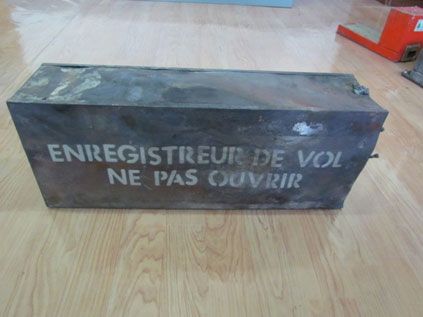
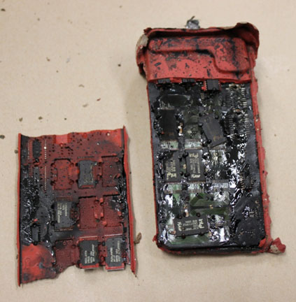
The National Transportation Safety Committee (NTSC) of Indonesia is responsible for investigating this accident. The aircraft carried an Ag-Nav GPS-based guidance and track monitoring system which the NTSC downloaded using conventional techniques. The normal download yielded data prior to the accident flight. The NTSC requested specialist assistance from the Australian Transport Safety Bureau (ATSB) to recover any accident flight data from the Ag-Nav system non-volatile memory chips that may not yet have been written to the unit's normal file system.

In accordance with clause 5.23 of Annex 13 to the Convention on International Civil Aviation (ICAO Annex 13), and to provide for the necessary protections of the Ag-Nav information, the ATSB appointed an Accredited Representative to assist the NTSC and initiated an investigation under the Australian Transport Safety Investigation Act 2003.

Download, examination and correspondence with the unit's manufacturer yielded no additional data beyond that retrieved in Jakarta. The latest available data from the Ag-Nav unit was found to be on 10 May 2013 consequently no accident flight data was available to assist the NTSC investigation team.

A report detailing the download and data examination was provided to the NTSC on 29 October 2013.

All inquiries regarding the investigation into this accident should be forwarded to the National Transportation Safety Committee of Indonesia.

National Transportation Safety Committee 
Ministry Of Transportation Republic Of Indonesia 
Transportation Building 3rd Floor
Jalan Medan Merdeka Timur No. 5
Jakarta Pusat 10110
Indonesia

Phone  :  +62 21 384 7601
Email    :  knkt@dephub.go.id

Website: http://knkt.dephub.go.id/knkt/ntsc_home/ntsc.htm

______________

Released in accordance with section 25 of the Transport Safety Investigation Act 2003.

Occurrence summary

Investigation number AE-2013-145
Occurrence date 11/05/2013
Location North Rawajiti, Lampung, South Sumatra, Indonesia
State International
Report release date 11/11/2013
Report status Final
Investigation level Defined
Investigation type Occurrence Investigation
Investigation status Completed
Mode of transport Aviation
Aviation occurrence category Collision with terrain
Occurrence class Accident
Highest injury level Fatal

Aircraft details

Manufacturer Pacific Aerospace Corporation
Model Fletcher FU24-950
Registration PK-PNC
Sector Turboprop
Damage Destroyed

Collision with terrain involving a Robinson R44, VH-UGC, Mount Buller, Victoria, on 6 November 2013

Summary

On 6 November 2013, the pilot of a Robinson R44 helicopter, registered VH‑UGC, was conducting a private flight from Latrobe Valley to Mount Buller, Victoria, with three passengers onboard.

At about 1425 Eastern Daylight-savings Time, the helicopter arrived overhead the Mount Buller Township. Two orbits at about 500 ft above ground level (AGL) were conducted to assess the landing area (helipad), the wind conditions and confirm the outside air temperature.

The pilot then commenced an approach to the helipad. When in an out-of-ground-effect hover, he conducted a power check at 21 inches hg manifold pressure. He then reduced the engine power to 18 inches hg and reported that, when about 30 m from the helipad, the helicopter became a bit unstable. He then raised the collective, but the engine appeared to lose power. He attempted to increase the power, but the engine appeared not to respond.

As the front of the helicopter’s skids were about to touch down, the pilot applied full forward cyclic, and reported experiencing mast bump. In response, he raised the collective lever. The low rotor revolutions per minute (RRPM) horn then sounded and the pilot reported the helicopter felt as if it was going to fall backwards. The helicopter rolled onto its side and came to rest about 9 m down an embankment. The helicopter was substantially damaged and the passengers were uninjured.

To maintain a steady hover, an increase in the weight of the helicopter requires more engine power. Increases in altitude and temperature reduce air density, and consequently the engine’s ability to produce power. Mount Buller helipad was at an elevation of 5,400 ft above mean sea level. The pilot reported that the helicopter was at a gross weight of about 1,048 kg when it landed.

Aviation Short Investigation Bulletin - Issue 25

Occurrence summary

Investigation number AO-2013-203
Occurrence date 06/11/2013
Location Mount Buller
State Victoria
Report release date 20/01/2014
Report status Final
Investigation level Short
Investigation type Occurrence Investigation
Investigation status Completed
Mode of transport Aviation
Aviation occurrence category Collision with terrain
Occurrence class Accident
Highest injury level Minor

Aircraft details

Manufacturer Robinson Helicopter Co
Model R44
Registration VH-UGC
Serial number 12051
Sector Helicopter
Operation type Private
Departure point Latrobe Valley, Vic.
Destination Mount Buller, Vic.
Damage Substantial

Tail strikes during landing involving Bombardier DHC-8 402, VH-QOT and VH-QOS, Brisbane Airport, Queensland, on 5 November 2013 and Roma Airport, Queensland, on 11 December 2013

Final report

What happened

On 5 November 2013 and 11 December 2013, two Dash 8-400 aircraft, registered VH-QOT and VH-QOS, were being operated by QantasLink on scheduled passenger flights from Roma to Brisbane and Brisbane to Roma, Queensland respectively. Both flights were crewed by a training captain, operating as pilot monitoring, and a trainee first officer, operating as pilot flying.

Although the two approaches utilised different flap settings, both were conducted using a propeller setting of 1,020 RPM. The early, initial and final stages of the approaches were unremarkable. Both training captains reported that as the aircraft approached the flare, they thought that the respective trainees had handled the approach well.

During landing, both trainees arrested the descent rate by raising the nose of the aircraft. In both cases the maximum pitch attitude was exceeded and the aircraft’s tail contacted the runway. Each aircraft sustained impact and abrasion damage to the fuselage skin and buckling of internal structures in the area of the tail strike sensor.

What the ATSB found

The ATSB’s found that in the last 50 ft of both approaches to land, the pilot flying did not manage engine power commensurate with their aircraft's declining energy state. This induced the pilot to pitch up in each case to control the descent rate and exceed the pitch angle limits.

The ATSB also identified that varied emphasis on the appropriate handling technique and pitch attitude awareness during first officer training did not assure consistent application of an appropriate landing technique in the Dash 8-400 aircraft.

Finally, the use of 15° of landing flap resulted in a margin of 1.9° between the nominal landing flare pitch angle and the tail strike angle. That compared with a margin of 3.9° when using 35° of flap and a typical margin for other transport aircraft of over 5°.

What's been done as a result

In response to these occurrences, QantasLink issued several flight operational bulletins that provided additional information and guidance to assist pilots manage engine power and pitch attitude during landing. In addition, the training provided to training captains has been modified and specific training for pitch monitoring and landing recovery has been incorporated into the cyclic simulator training and proficiency program.

QantasLink flight operations analysis for the 12 months following the introduction of the above safety actions showed a significant reduction in the number of high pitch attitude landing events.

Safety message

Dash 8 pilots are reminded of the inherent risk of tail strike during landing. While all Dash 8-type aircraft have pitch limitations, they are most restrictive on the -400 and -300 variants. Pitch attitudes in excess of 6° must be avoided.

Reducing engine power to idle during the landing flare can cause a sudden and unexpected increase in drag and reduction of lift. An excessive rate of descent during landing must be corrected by applying power. The temptation to control the decent rate by pitching up must be avoided.


The occurrences

VH-QOT

On 5 November 2013, a Bombardier Inc DHC-8-402 (Dash 8-400) aircraft, registered VH-QOT, was being operated by QantasLink on a scheduled passenger flight from Roma to Brisbane, Queensland. The flight crew comprised a training captain, operating as the pilot monitoring (PM)[1], and a trainee first officer (FO), operating as the pilot flying (PF).

The flight crew had signed on at their home base, Brisbane, at 1045 Eastern Standard Time[2] and were rostered to operate two Brisbane to Roma and return flights. The FO conducted the landing at Roma without incident using 35° of landing flaps (Flap 35).

The aircraft departed Roma for Brisbane at 1323 and a visual approach to runway 19 at Brisbane Airport was commenced at about 1420. The weather for the approach included a crosswind of 18 kt and the possibility of light windshear at about 200 ft above the ground. Fifteen degrees of landing flaps (Flap 15) and a propeller RPM of 1,020 (see the section titled Landing configuration guidance) were selected and the target approach speed was increased due to the prevailing wind conditions.

The captain reported that despite the strong crosswind, the approach to land was well handled. Both the captain and the FO recalled that the initial flare[3] led to a smooth/light touchdown and that the aircraft immediately became airborne again. The aircraft subsequently flew level at about 10 ft before settling onto the runway about 4 seconds later.

Engine power, which had been set to flight idle as the aircraft descended through about 10 ft during the initial flare, remained at flight idle through to the second touchdown. That touchdown included a bounce, during which the main landing gear was briefly unloaded. The pitch attitude during this period reached 7.5° nose‑up and the aircraft landed at 1425.

After the second touchdown, which the crew described as a normal Flap 15 landing, the TOUCHED RUNWAY warning light illuminated. Believing the warning to be spurious, the crew contacted air traffic control who, after conducting a runway inspection, advised there was debris on the runway consistent with a tail strike.

VH-QOS

On 11 December 2013, the flight crew of a QantasLink Dash 8-400 aircraft, registered VH‑QOS, signed on at their home base, Brisbane, at 1105. The crew, comprising a training captain and a trainee FO, was rostered to operate a return scheduled passenger flight from Brisbane to Emerald, Queensland, followed by a return flight to Roma.

The FO was the PF for the flight to Emerald and the captain was the PF for the return flight to Brisbane. The landing configuration used for those two landings was Flap 15 and a propeller RPM of 850.

The flight to Roma departed Brisbane at 1655. Prior to descent into Roma, the crew conducted an approach and a threat and error management briefing that discussed the intention to use Flap 35 and a propeller RPM of 1,020 for landing. The briefing also included a reminder not to retard the power too quickly as the use of idle with 1,020 RPM would create more drag than at 850 RPM.

The circuit and approach to land proceeded normally and the captain recalled that, as the aircraft passed through 50 ft, the FO had managed the approach well. At about 30 ft, and as the FO began to flare the aircraft to land, the captain observed the airspeed reducing and called for the FO to apply power. The airspeed reduce further and the aircraft contacted the runway firmly. The captain believed the engine torque at this time was about 20 per cent.

The FO reported being aware of the need not to reduce the power too quickly and was surprised by the captain’s call for additional power. By the time the FO comprehended the intent of the call for more power, the aircraft had contacted the runway. Engine power had been set to flight idle during the flare and touchdown occurred at 1802. The pitch attitude immediately prior to touchdown was 8.4° nose‑up.

Despite the firm landing, the captain believed it to be relatively normal and did not hear any unusual airframe noises. During the landing roll, the crew notice that the TOUCHED RUNWAY warning light was illuminated. The aircraft was taxied to the parking bay and after disembarkation, the crew visually confirmed that a tail strike had occurred.

__________

  1. Pilot flying (PF) and pilot monitoring (PM) are procedurally assigned roles with specifically assigned duties at specific stages of a flight. The PF does most of the flying, except in defined circumstances; such as planning for descent, approach and landing. The PM carries out support duties and monitors the PF’s actions and aircraft flight path.
  2. Eastern Standard Time (EST) was Coordinated Universal Time (UTC) + 10 hours.
  3. Final nose-up pitch of a landing aeroplane to reduce the rate of descent to approximately zero at touchdown.

Safety issues and actions

The ATSB did not identify any organisational or systemic issues that might adversely affect the future safety of aircraft operations. However, whether or not the ATSB identifies safety issues in the course of an investigation, relevant organisations may proactively initiate safety action in order to reduce their safety risk. The ATSB has been advised of the following proactive safety action in response to this occurrence.

Proactive safety action taken by QantasLink

In response to the tail strikes, QantasLink made a number of changes to their training procedures including:

  • changes to training captain selection criteria and to the training provided to training captains
  • amendments to training captain proficiency lesson plans to include pitch attitude monitoring, dedicated training to raise awareness of potential candidate errors and intervention/recovery training
  • implementation of a pitch attitude monitoring and landing recovery training session as part of the cyclic simulator training and proficiency program
  • implementation of a new rostering protocol that, where a first officer’s training is disrupted by a period of more than 7 days, they will receive additional training events.

QantasLink also issued several flight operational bulletins that:

  • provided additional information and guidance on landing techniques covering the approach to land, flare, and appropriate use of engine power
  • cautioned that reducing power to idle close to the ground or in the flare may cause a sudden and unexpected increase in drag along with a reduction of lift
  • cautioned that should a higher-than-normal decent rate be experienced during the landing phase, the temptation to control this decent rate by pitching up must be avoided
  • required all flight crew to review the pitch awareness video by a set date
  • reminded flight crew of the standard pitch awareness calls and associated actions
  • provided guidance for bounced and skipped landing recovery
  • placed restrictions on the use of 1,020 RPM for landing.

Those bulletins have subsequently been incorporated into QantasLink’s operations manuals.

Proactive safety action taken by Bombardier Inc

On 21 September 2016, Bombardier Inc advised that, following a review of the landing guidance provided in their pitch awareness video, they were in the process of amending the associated Flight Operations Service letter to include the following:

PURPOSE

This Flight Operations Service Letter is issued to provide landing guidance for Tailstrike Avoidance on the Q400

DISCUSSION

There have been a number of tailstrikes recently resulting in damage to the aft lower fuselage.

The Aircraft Flight Manual (AFM) is the only approved document with respect to flight management of the aircraft.

Bombardier wishes to remind Operators to be mindful of aircraft pitch attitude during the flare (the following extracted from Section 4.4 of the AFM)

NOTE

To decrease the landing descent rate and not exceed a pitch attitude of 6°, when the landing descent rate is higher than desired, power will be required in the landing flare through to touchdown.

To decrease the landing descent rate at airport altitudes greater than 5,000 ft, it may be necessary to maintain power in the landing flare through to touchdown.

CAUTION

Pitch attitudes greater than 6° in the landing flare may cause the fuselage to contact the runway.

A Pitch Awareness Training video was developed as general guidance to avoid aft lower fuselage contact during the landing and should be considered as examples of approaches and landings. A nominally flat pitch attitude should be expected for flap 35°, while a flap 15° approach will be flown slightly nose-up, when the appropriate VREF speed is adhered to.

While some Q400 operational tailstrikes have included unstable approaches, all Q400 tailstrikes during the landing flare occurred as a result of not respecting the AFM Caution of 6° during the landing flare.

It is important to focus attention on speed management during the approach, which in turn will allow the aircraft to stabilize the appropriate pitch attitude. As each approach for landing can be subtly different, so can the pitch attitude. Management of the absolute pitch attitude during the landing flare to less than 6° at touchdown, as well as increasing power to reduce the sink rate will help flight crew avoid tailstrikes.

Sources and submissions

Sources of information

The sources of information during the investigation included the:

  • flight crew of VH-QOT and VH-QOS
  • flight data recorders of VH-QOT and VH-QOS
  • QantasLink
  • Bombardier Inc.

Submissions

Under Part 4, Division 2 (Investigation Reports), Section 26 of the Transport Safety Investigation Act 2003 (the Act), the ATSB may provide a draft report, on a confidential basis, to any person whom the ATSB considers appropriate. Section 26 (1) (a) of the Act allows a person receiving a draft report to make submissions to the ATSB about the draft report.

A draft of this report was provided to the flight crew of VH-QOT and VH-QOS, QantasLink, Bombardier Inc, the Transportation Safety Board of Canada and the Civil Aviation Safety Authority.

Submissions were received from a flight crew member of VH‑QOT, QantasLink, Bombardier Inc and the Civil Aviation Safety Authority. The submissions were reviewed and, where considered appropriate, the text of the draft report was amended accordingly.

Context

Flight crew information

Both training captains held an Air Transport Pilot (Aeroplane) Licence, a multi-engine command instrument rating and a valid Class 1 Medical Certificate. Both first officers (FO) held a Commercial Pilot (Aeroplane) Licence, a multi-engine command instrument rating and a valid Class 1 Medical Certificate. A summary of each pilot’s aeronautical experience is listed at Table 1.

Table 1: Aeronautical experience summary

Table 1: Aeronautical experience summary
First officer of VH-QOT

The FO commenced training with QantasLink on 23 April 2013. The following 6 weeks comprised mainly induction and ground training and was completed by early June. That training was conducted with the majority of available days being utilised.

The FO conducted two of the required four fixed base procedural training sessions on 5 and 6 June 2013. That training was followed by an extended period of inactivity and the remaining two sessions were not conducted until 11 and 16 July 2013.

The FO’s endorsement training, which consisted of 12 sessions in a flight simulator, commenced on 23 July 2013. That training included periods of inactivity and was not completed until 10 September 2013, a period of 50 days. Allowing for days off and rest, this endorsement training should typically take between 20 and 30 days to complete.

The FO’s line training, conducted by a suitably-qualified training captain, commenced on 26 September 2013. The FO had completed 24 days of line training prior to the tail strike on 5 November 2013.

First officer of VH-QOS

The FO commenced ground training on 3 June 2013. The FO’s training roster for June and the first 2 weeks of July included induction and ground training with most available days being utilised. For the remainder of July and up to late August, the pilot was on standby for 26 of the 30 available training days.

The FO commenced fixed base procedural training on 27 August 2013 and completed that training on 4 September 2013.

The FO’s endorsement training commenced on 7 September 2013. That training, conducted during the remainder of September and all of October, included periods of inactivity and took 55 days to complete the stipulated 12 sessions.

The FO commenced line training on 5 November 2013. The FO had completed 13 days of line training prior to the tail strike on 11 December 2013.

Fatigue assessment

None of the operating crew members reported any fatigue concerns or health issues in relation to the occurrence flights.

The captain and FO of VH-QOT were on day 4 of a 5-day duty cycle. Both pilots reported being well rested and fit for duty. The current cycle was preceded by 2 days free of duty.

The captain and FO of VH-QOS had completed 10 days free of duty. Both pilots reported being well rested and fit for duty.

Aircraft information

Landing guidance

Bombardier Inc (Bombardier), the aircraft manufacturer, provided landing guidance in its Dash 8 aircraft operating and flight manuals. Normal landings could be conducted with any combination of 15° or 35° of landing flaps (Flap 15 or Flap 35) and a propeller RPM setting of 850 or 1,020. A preferred or optimal landing configuration was not specified.

In addition, a Bombardier pitch awareness video and service letter highlighted the length and susceptibility of the Dash 8-400 aircraft to tail strike as compared to the shorter fuselage variants. The video also detailed the:

  • location of the possible rear fuselage tail strike area
  • pitch angles at which the tail may contact the ground
  • importance of pitch awareness and not exceeding 6° of nose-up pitch during landing
  • typical approach to land pitch attitudes of about 0° to 1° nose up for Flap 15 and about 2° to 3° nose down for Flap 35
  • attitude change during the flare to land of approximately 5° for both Flap 15 and Flap 35 approaches
  • importance of controlling excessive rates of descent by increasing power rather than increasing the nose-up attitude near the ground. An increase in power increases the airflow over the wings directly behind the propellers and, therefore, increases lift even if the forward velocity does not change. If an excessive rate of descent close to touchdown cannot be corrected with power, a go around must be initiated.
Dash 8-400 touched runway indicating system

Most, if not all air transport aircraft have pitch limitations for take-off and landing in order to prevent the aft fuselage contacting the runway. Due to the design and length of the fuselage, the Dash 8‑400 can experience tail contact on landing at pitch attitudes as low as 6.9°.

Additionally, due to reduced flare capability at lesser degrees of flap, there is a greater probability of aft fuselage/runway contact with landing flaps set at 15° than with flaps set at 35°.

The Dash 8-400 is fitted with a touched runway detection system that includes a frangible switch/sensor located on the underside of the aft fuselage (Figure 1). In the event of a tail strike, a TOUCHED RUNWAY warning light, located on the overhead warning light panel in the cockpit, illuminates.

At touchdown, depending on main gear oleo compression and curvature of the runway surface, tail contact will occur at between 6.9° and 7.5° nose up.

Figure 1: Touched runway detection system – sensor location

Figure 1: Touched runway detection system – sensor location

Source: Bombardier, modified by the ATSB

Dash 8-300 advisory display

The Dash 8-300 is fitted with an advisory display indicator (Figure 2), which is located in a prominent position on the captain’s and FO’s instrument panel. The four-line colour display shows operational, warning and caution messages including LDG ATT 6 DEG. This message advises flight crew that the landing attitude has reached the certification limit.

Figure 2: Dash 8-300 advisory display

Figure 2: Dash 8-300 advisory display

Source: QantasLink, modified by the ATSB

The Dash 8-400 is not fitted with an advisory display. Operational, warning and caution messages in the Dash 8-400 are displayed on the primary flight and navigation displays however, there is no caution message for landing attitude. The primary flight display is located on the pilot’s instrument panel and includes an attitude indicator graduated in increments of 2.5°. During landing in the Dash 8-400, the monitoring pilot is required to monitor the attitude indicator and make advisory calls if the pitch attitude reaches 5° or 6°.

Aircraft damage

Both aircraft sustained impact and abrasion damage to the aft fuselage skin and buckling of internal structures in the area of the touched runway sensor (Figures 3 and 4).

Figure 3: Damage to the tail section of VH-QOT (looking aft)

Figure 3: Damage to the tail section of VH-QOT (looking aft)

Source: ATSB

Figure 4: Damage to tail section of VH-QOS (looking aft)

Figure 4: Damage to tail section of VH-QOS (looking aft)

Source: ATSB

Flight recorders

Flight data recorder - VH-QOT

Analysis of recorded data indicated that the flare to land was commenced at about 20 ft. The airspeed at that time was 122 kt, slightly above the vref[4] of 119 kt for the approach but below the target approach speed (vapp)[5] of 127 kt and engine torque about 10 per cent. Expected torque for a Flap 15 landing is about 17 per cent.

During the flare, due to the prevailing crosswind, the FO conducted a ‘de-crabbing manoeuvre’ to align the aircraft with the runway. Flight idle was selected as the aircraft descended through about 10 ft and the pitch attitude during the flare reached a maximum of 7.3°. The recorded data did not register ground contact associated with that flare. However, as the flight crew recalled that initial touchdown was very light, there may have been insufficient weight applied to the main landing gear sensor to record the initial runway contact. The aircraft floated just above the runway for a period of about 4 seconds during which time the airspeed reduced to 116 kt with no change in power. vref was 119 kt.

The pitch attitude at the second touchdown, which included a bounce as the main gear temporarily unloaded, was 7.5°. A data plot is included at appendix A.

Flight data recorder - VH-QOS

Analysis of recorded data indicated that between 100 ft and 30 ft, the airspeed reduced from 127 kt to 115 kt. The target approach speed was 120 kt and Vref was 113 kt. Engine torque during this period was about 14 per cent, significantly below the expected torque for a Flap 35 landing of about 24 per cent.

The flare to land was commenced at about 30 ft and at about 10 ft, engine power was reduced to flight idle. Touchdown, which included a bounce as the main gear temporarily unloaded, occurred at an airspeed of 100 kt, 13 kt below the Vref of 113 kt. The pitch attitude was 8.4° at that time. A data plot is included at appendix B.

Operator information

First officer training

General

Prior to commencing line operations, all FOs were required to complete the:

  • QantasLink induction program
  • Dash 8-400 ground engineering course and other mandatory ground courses, including viewing the Bombardier pitch awareness video
  • Dash 8-400 endorsement program, which was conducted in the aircraft simulator.

The endorsement program comprised four fixed‑base procedural training sessions and 12 full flight simulator training sessions. The final session included an assessment of the trainee’s competency to progress to line training in the aircraft.

FO line training was conducted on revenue flights under the supervision of an appropriately‑qualified training captain. FOs received between 75 and 100 hours of training followed by a check-to-line assessment.

First officers of VH-QOS and QOT

The FOs of VH-QOS and VH-QOT reported that their simulator training was sporadic, due to a combination of simulator unserviceability and rostering. QantasLink identified a similar irregular training pattern with other trainee FOs due to extended periods of time being on‑call to conduct training.

Pitch attitude awareness

The QantasLink Dash 8-400 flight crew operating manual (FCOM) highlighted that pilot awareness of pitch attitude during touchdown was essential to avoid a touched runway occurrence and cautioned against pitch attitudes in excess of 6°.

The aircraft typically requires a 5° attitude change during the landing flare. When landing with Flap 15, the approach attitude is close to zero so touchdown at around 5° nose up can be expected. When landing with Flap 35 the approach attitude is around 2° nose down with touchdown at about 3° nose up.

The FCOM indicated that the pilot monitoring was required to note the pitch attitude during the landing flare and make a number of advisory calls if the pitch attitude reached 5° or 6° (Table 3).

Table 3: Pitch attitude advisory calls

Pilot monitoringPilot flyingAction
‘Five degrees’‘Checked’Check attitude and power and adjust if necessary, to avoid further increase.
‘Pitch’‘Correcting’Take immediate action to ensure pitch attitude does not exceed 6°.

The FCOM also stated that if the sink rate was too high during the roundout and flare, it was not to be corrected by pitching up beyond 6°. In such cases, an appropriate power increase could be used to further reduce the sink rate or, if necessary, a go around should be conducted.

Landing configuration guidance

At the time of the occurrences, QantasLink did not provide any landing configuration guidance or information additional to that provided by Bombardier. QantasLink did not specify a preferred or optimal landing configuration.

As detailed previously, normal landings could be conducted with any combination of Flap 15 or Flap 35 and a propeller RPM setting of 850 or 1,020. The selected landing configuration was at the discretion of the captain.

Flap 35 provides for a slower approach speed, reduced landing distances and a greater tail strike margin. Despite this, both training captains reported that most pilots preferred to use Flap 15 because the aircraft was more responsive, easier to handle and easier to land. Flap 35 was rarely used for other than training purposes.

A propeller RPM setting of 850 produces less noise in the cabin and less propeller drag. Reduced propeller drag lessens the aircraft’s deceleration if the engine power is reduced to flight idle prematurely. In the event of a go around, propeller RPM will automatically increase to 1,020 RPM. An RPM of 1,020 provides increased sensitivity to power lever inputs and greater control over aircraft performance, and is therefore often used in windy or turbulent conditions.

Analysis of high pitch attitude events

About 5 months prior to these occurrences, QantasLink identified an emerging trend in high pitch attitude occurrences during landing. In response, a focused flight operations analysis was commenced, and remained ongoing, at the time of these occurrences.

In response to these two tail strikes, QantasLink re‑analysed the data and identified an increasing trend of high pitch attitude landings conducted by FOs under training. That finding resulted in the implementation of a number of measures designed to reduce the risk of tail strikes (see the section titled Safety actions).

Information provided by QantasLink identified that, in the 12 months following the introduction of those safety measures, the number of high pitch attitudes during landing reduced significantly.

Previous similar occurrences

At the time of these occurrences, there had been 19 other tail strikes worldwide involving Dash 8‑400 aircraft. Eighteen of these were during landing.

There have been two other previous tail strike occurrences involving Australian-registered Dash 8 aircraft. However, they involved earlier -100 or -200 series aircraft and appear to have been the result of wind‑related environmental effects.

__________

  1. Vref is the minimum speed at which a transport category aircraft complies with those handing criteria associated with approach and landing and is typically 1.3 times the aircraft’s landing configuration stall speed.
  2. Vapp is the approach target speed for a transport category aircraft and provides a speed margin over and above vref based on the prevailing local environmental conditions.

Findings

From the evidence available, the following findings are made with respect to the tail strike occurrences involving Dash 8-400 aircraft, registered VH-QOT, at Brisbane Airport, Queensland on 5 November 2013 and Dash 8-400 aircraft, registered VH-QOS, at Roma Airport, Queensland on 11 December 2013. These findings should not be read as apportioning blame or liability to any particular organisation or individual.

Contributing factors

  • In the last 50 ft of both approaches to land, the first officer, who was the pilot flying, did not manage engine power commensurate with the aircraft's declining energy state, inducing the first officer to inadvertently pitch up to control the descent rate and exceed the pitch angle limits.
  • Varied emphasis on the appropriate handling technique and pitch attitude awareness during first officer training did not assure consistent application of an appropriate landing technique in the Dash 8-400 aircraft.

Other findings

  • The use of Flap 15 for landing results in a margin of 1.9° between the nominal landing flare angle and the tail strike angle, compared to a margin of 3.9° when using Flap 35 and a typical margin for other transport aircraft of over 5°.
  • About 5 months prior to these occurrences, QantasLink identified an emerging trend in high pitch attitude occurrences during landing. In response, a focused flight operations analysis was commenced, and was ongoing, at the time of these occurrences.

Safety analysis

Introduction

Due to its design and length, the Dash 8-400 has an increased risk of tail strike on landing that must be managed by the flight crew. The tail strikes that occurred on 5 November and 11 December 2013 took place when the affected aircraft were being flown by flight crew members under training. Both tail strikes were characterised by insufficient application of engine power and overpitching during the landing flare.

This analysis will discuss the development of the tail strikes, the operator’s training and the risk controls in place at the time of the occurrences.

The tail strikes

While they had different flap settings, both approaches were conducted using a propeller RPM setting of 1,020. While that RPM setting resulted in higher overall drag compared to that associated with the alternate 850 RPM, the early, initial and final stages of the approaches were unremarkable. Both training captains reported that as the aircraft approached the flare, they thought that the respective trainee first officers (FO) had, as the pilot flying, handled the approach well.

The purpose of the flare is to reduce the rate of descent prior to touchdown. In the Dash 8-400, which has a relatively low tail strike attitude, the flare needs to be effected by careful use of pitch attitude change and engine power management.

In general terms, increasing the pitch attitude increases the lift generated by the wings and will therefore reduce the rate of descent. Due to the design of the Dash 8, the rate of descent can also be reduced by increasing engine power. Any increase in engine power will increase the airflow over the wing and produce additional lift. Conversely, reducing power to flight idle too early can result in a loss of lift and a significant increase in propeller drag, particularly when 1,020 RPM is used.

While not necessarily intuitive, a high sink rate during the flare must not be corrected in the Dash 8-400 by pitching up beyond 6°, as this could result in a tail strike. The correct response is to increase power or, if necessary, conduct a go around.

VH-QOT

The aircraft entered the landing flare at about the desired airspeed and with a power setting that was about 7 per cent lower than normal for the selected flap setting. Although the FO had to contend with a reasonably strong crosswind, the associated de-crabbing manoeuvre appears to have been well handled and not directly related to the tail strike.

During the flare, the sink rate was arrested by increasing the pitch attitude and power was reduced to flight idle as the aircraft descended through about 10 ft. The reduction of power to flight idle resulted in a loss performance and introduced a significant amount of propeller drag. Contrary to the recommended procedure, the rate of descent was reduced by further increasing the pitch attitude to 7.3°.

Following the initial flare and light touchdown, the pitch attitude was reduced to achieve level flight and the aircraft continued to float above the runway with idle power for about 4 seconds. The lack of engine power during this period resulted in a continued loss of performance that was instinctively countered by a further pitch attitude increase beyond the recommended 6° limit. This resulted in the tail contacting the runway.

VH-QOS

In the case of VH-QOS, the aircraft arrived at the flare with an already‑decreasing airspeed and insufficient engine power. These conditions were symptomatic of insufficient performance for the stage of flight. Reducing engine power to flight idle during the flare further reduced the aircraft’s performance and introduced a significant amount of propeller drag.

The inadequate performance, significant propeller drag and additional drag associated with Flap 35 resulted in the airspeed reducing rapidly from 115 kt to 100 kt. While the corresponding loss of lift should have been countered by an increase in engine power, the FO intuitively pitched up further. At touchdown, the airspeed was 13 kt below the minimum airspeed and the pitch attitude was 8.4°.

Conclusion

The selection of flight idle during the landing flare, possibly aggravated by the increased drag associated with a propeller setting of 1,020 RPM, resulted in a significant loss of performance that was incorrectly countered by the respective FO by increasing the aircraft’s pitch attitude.

In both cases, the FO did not manage the engine power commensurate with the aircraft's declining energy state, inducing them to inadvertently pitch up to control the descent rate and exceed the aircraft’s pitch angle limit.

Endorsement training

QantasLink’s identification of an emerging trend in high pitch attitude landings prior to these occurrences highlights the value of analysing flight operations data. The resulting focus on data analysis, while not preventing these occurrences, was a proactive response by QantasLink.

Additional analysis of flight operations data by QantasLink following these two occurrences identified an emerging trend of high pitch attitude occurrences during landing among the trainee FOs. There was a significant reduction in the number of these occurrences in the 12 months following the introduction of safety measures. These measures included:

  • additional landing guidance
  • additional training captain guidelines
  • the implementation of pitch- and landing-focused simulator/line training programs.

This supports the conclusion that the occurrences took place as a result of inadequate landing techniques and pitch attitude awareness deficiencies among those FOs.

Simulator training, both endorsement and recurrent, can be a very powerful and effective training aid. The endorsement training for the FOs that were involved in these two occurrences included minimal normal landings and did not include any specific training to address the risk of tail strike. Had the syllabus included simulator training to reinforce the correct procedure for reducing higher‑than‑normal descent rates on approach and pitch awareness, the tail strikes may not have occurred.

Both FOs reported that their training was conducted over an extended period of time with periods of inactivity between simulator sessions. QantasLink identified that the training schedule for other recently‑employed FOs exhibited similar patterns and in some cases took even longer to complete. Such sporadic training may not provide trainees with adequate opportunity to consolidate and retain newly‑learned skills. However, as the content of the training did not adequately prepare the FOs to land the Dash 8-400 aircraft, it is difficult to assess whether the irregular training pattern may have, in isolation, influenced the development of these occurrences. The potential for the irregular training to have compounded any difficulties experienced by the FOs during their training could not be discounted.

Risk controls

Pitch monitoring

The operator’s procedures required the pilot monitoring to make 5° and 6° pitch attitude calls. However, on both occurrences the pitch attitude went from an acceptable attitude to over 7° in a very short period of time. Given that both flying pilot FOs were under training, it is likely that the training captain’s focus in each case was directed more towards the manipulation of the aircraft rather than the existing pitch attitude.

In the case of VH-QOT, the pitch attitude during the initial flare changed from 3.2° to 7.3° in 2 seconds. There may have been an opportunity for the captain to notice and call the excessive pitch attitude during the 4 second float. However, it appears their focus was more towards ensuring the aircraft settled onto the runway than its pitch attitude.

In the case of VH-QOS, the pitch attitude changed from 1.2° to 8.4° in 1.5 seconds. During this short period the captain called for the FO to add power to arrest the rapidly‑reducing airspeed. The situation developed so rapidly that there was insufficient time for the captain to recognise and make the required pitch attitude calls.

Earlier versions of the Dash 8 are fitted with an advisory display that provides a visual caution when the pitch attitude reaches 6°. The display is located in a prominent position and, if fitted to the occurrence aircraft, may have been of assistance in bringing the high pitch attitude to the attention of the crew. However, given how quickly the situations developed, it seems unlikely that a similar caution would have proved effective in preventing these tail strikes.

Landing flap selection

Most air transport aircraft use flap settings of about 30° or greater for landing. Those settings provide for tail strike margins in excess of 5°. Despite the operational benefits of using Flap 35, full flap on the Dash 8-400, flight crew appear to prefer the use Flap 15 due to the aircraft being more responsive, easier to handle and easier to land. While the use of Flap 15 does provide a performance benefit in the event of a go-around, none of the airports to which QantasLink operated required its use.

While flight crews may prefer the use of Flap 15 for landing, the margin between a normal approach attitude and tail strike attitude in that configuration is reduced from about 4° to about 2°.

Appendices

Appendix A – VH-QOT approach and landing data

Appendix A – VH-QOT approach and landing data

Source: ATSB

Appendix B – VH-QOS approach and landing data

Appendix B – VH-QOS approach and landing data

Source: ATSB

Purpose of safety investigations & publishing information

Purpose of safety investigations

The objective of a safety investigation is to enhance transport safety. This is done through:

  • identifying safety issues and facilitating safety action to address those issues
  • providing information about occurrences and their associated safety factors to facilitate learning within the transport industry.

It is not a function of the ATSB to apportion blame or provide a means for determining liability. At the same time, an investigation report must include factual material of sufficient weight to support the analysis and findings. At all times the ATSB endeavours to balance the use of material that could imply adverse comment with the need to properly explain what happened, and why, in a fair and unbiased manner. The ATSB does not investigate for the purpose of taking administrative, regulatory or criminal action.

Terminology

An explanation of terminology used in ATSB investigation reports is available here. This includes terms such as occurrence, contributing factor, other factor that increased risk, and safety issue.

Publishing information 

Released in accordance with section 25 of the Transport Safety Investigation Act 2003

Published by: Australian Transport Safety Bureau

© Commonwealth of Australia 2016

image_5.png

Ownership of intellectual property rights in this publication

Unless otherwise noted, copyright (and any other intellectual property rights, if any) in this report publication is owned by the Commonwealth of Australia.

Creative Commons licence

With the exception of the Coat of Arms, ATSB logo, and photos and graphics in which a third party holds copyright, this publication is licensed under a Creative Commons Attribution 3.0 Australia licence.

Creative Commons Attribution 3.0 Australia Licence is a standard form licence agreement that allows you to copy, distribute, transmit and adapt this publication provided that you attribute the work.

The ATSB’s preference is that you attribute this publication (and any material sourced from it) using the following wording: Source: Australian Transport Safety Bureau

Copyright in material obtained from other agencies, private individuals or organisations, belongs to those agencies, individuals or organisations. Where you wish to use their material, you will need to contact them directly.

Occurrence summary

Investigation number AO-2013-201
Occurrence date 05/11/2013
Location Brisbane Airport
State Queensland
Report release date 28/10/2016
Report status Final
Investigation level Defined
Investigation type Occurrence Investigation
Investigation status Completed
Mode of transport Aviation
Aviation occurrence category Ground strike
Occurrence class Incident
Highest injury level None

Aircraft details

Manufacturer Bombardier Inc
Model DHC-8
Registration VH-QOT
Serial number 4269
Aircraft operator QantasLink
Sector Turboprop
Operation type Air Transport High Capacity
Departure point Roma, Qld
Destination Brisbane, Qld
Damage Minor

Aircraft details

Manufacturer Bombardier Inc
Model DHC-8
Registration VH-QOS
Serial number 4263
Aircraft operator QantasLink
Sector Turboprop
Operation type Air Transport High Capacity
Departure point Brisbane, Qld
Destination Roma, Qld
Damage Minor

Loss of control involving a Cessna 172, VH-IGS, 93 km south-east of Port Pirie Airport, South Australia, on 31 October 2103

Summary

On 31 October 2013, a Cessna 172 aircraft, registered VH-IGS, departed Parafield, on a private flight to the Gum Creek area near Clare, South Australia. The pilot was the sole occupant on board.

The pilot had flown to Parafield earlier in the morning to pick up a part needed to repair a hay cutting machine. The pilot felt pressure to get the part back to the property and repair the machine so that the harvest could continue.

At about 1300 central daylight time, the aircraft arrived overhead a back road the pilot had selected in the Gum Creek area. His intention was to land as close as possible to the hay machine. After conducting two precautionary searches over the road and identifying some powerlines, he commenced the approach onto the road.

Just as the aircraft was touching down, a gust of wind struck the aircraft from the right, moving it rapidly to the left. The pilot attempted to initiate a go-around, but the aircraft continued further left.  The left wing struck a large tree and was severed, and the aircraft was further damaged as it continued through a gate and fence. The pilot sustained minor injuries, and the aircraft was substantially damaged.

  Aviation Short Investigation Bulletin - Issue 25

Occurrence summary

Investigation number AO-2013-198
Occurrence date 31/10/2013
Location 93 km SE Port Pirie aerodrome
State South Australia
Report release date 20/01/2014
Report status Final
Investigation level Short
Investigation type Occurrence Investigation
Investigation status Completed
Mode of transport Aviation
Aviation occurrence category Loss of control
Occurrence class Accident
Highest injury level Minor

Aircraft details

Manufacturer Cessna Aircraft Company
Model 172
Registration VH-IGS
Serial number 17270677
Sector Piston
Operation type Private
Damage Substantial

Collision with terrain involving Bell 206L helicopter, VH-VDZ, at Melbourne, Victoria, on 2 November 2013

Final report

What happened

On 2 November 2013, the pilot of a Bell 206L-1 helicopter, registered VH-VDZ, was conducting passenger-carrying charter operations between Olympic Park oval and Flemington Racecourse, Melbourne, Victoria. At about 1830 Eastern Daylight-saving Time, the pilot prepared to reposition the helicopter from one of the temporary helipads at Olympic Park. There were no passengers on board.

As the pilot lifted the helicopter into a hover it started rolling about the right skid, which was in contact with the ground. The helicopter rapidly rolled further right until the main rotor blades struck the ground. A large amount of main rotor and other high energy debris was released from the helicopter and impacted a nearby marquee, a number of vehicles and a helicopter on an adjacent helipad. The pilot sustained minor injuries.

What the ATSB found

The ATSB found that the pilot did not identify and react to the helicopter’s right-skid low attitude in sufficient time to prevent the helicopter rolling over. In addition, an unsecured ballast bag was positioned on the left front floor of the helicopter, increasing the risk of injury to occupants. Further, the helicopter’s dual flight controls were removed to facilitate the flights. The person who removed the controls did not have the training or authorisation to conduct the maintenance procedure. The left cyclic stub cover was not installed, leaving the stub exposed. This resulted in the potential for the ballast bag to inhibit movement of the pilot’s cyclic control due to fouling of the left cyclic stub.

The ATSB identified safety issues relating to the availability of first aid and emergency response equipment at the oval and the proximity of the helipads to the perimeter fence and public access areas. Each increased the risk of injury to bystanders in the event of an accident.

What's been done as a result

For subsequent operations at the Olympic Park oval for the remainder of the event, the charterer positioned firefighting equipment at each helipad and first aid equipment was made available nearby. In addition, the helipads were repositioned further from the passenger marquee, and passengers were not loaded or unloaded if helicopters were in the process of landing or taking-off from adjacent helipads. Operations at the Olympic Park oval ceased following the 2013 carnival.

Safety message

This accident highlights the importance of coordinated control inputs by pilots during lift-off to control any roll, and if necessary smoothly lowering the collective in coordination with cyclic input to re-establish the helicopter’s weight evenly on the ground before any roll becomes excessive. The importance of properly securing any equipment, particularly if stowed in aircraft cockpits, and of the correct removal and re-fitting of dual flight controls to prevent any obstruction or fouling of the controls is emphasised.

In addition, this accident is a reminder of the risks involved when operating helicopters in public areas. Although the likelihood of a helicopter accident on the ground that results in injuries was found by the ATSB to be low, in the event of an accident, high energy rotor and other debris can travel large distances. Where possible, operators should consider larger distances around helicopter landing areas, in particular when operating close to public areas.

Sources and submissions

Sources of information

The sources of information during the investigation included the:

  • pilot of the helicopter
  • charterer of the helicopter
  • owner of the helicopter
  • Civil Aviation Safety Authority (CASA).

References

Wagtendonk, WJ 1996, Principles of Helicopter Flight, Aviation Supplies & Academics, Inc. Washington, USA.

Submissions

Under Part 4, Division 2 (Investigation Reports), Section 26 of the Transport Safety Investigation Act 2003 (the Act), the ATSB may provide a draft report, on a confidential basis, to any person whom the ATSB considers appropriate. Section 26 (1) (a) of the Act allows a person receiving a draft report to make submissions to the ATSB about the draft report.

A draft of this report was provided to the CASA, the aircraft owner, the charterer of the helicopter and the pilot.

Submissions were received from CASA, the charterer of the helicopter and the pilot. The submissions were reviewed and where considered appropriate, the text of the report was amended accordingly.

Context

The charterer[2secured the services of other operators in support of the passenger-carrying charter flights that day. This provided additional capacity to move passengers between Olympic Park oval and Flemington Racecourse during peak periods.

Personnel information

Pilot

The pilot held a Commercial Pilot (Helicopter) Licence and was endorsed on the Bell 206 (B206) helicopter. The pilot also held a valid Class 1 Aviation Medical Certificate.

The pilot indicated that, at the time of the accident, they had a total aeronautical experience of about 1,020 flying hours, which included about 50 hours flying B206 Jetranger helicopters and about 22 hours flying the B206 Longranger. The pilot’s most recent check flight was conducted on 21 January 2013 in a Robinson R44 helicopter. The pilot was not approved for pilot-permitted maintenance on the B206 in relation to the removal of flight controls (see Conduct of the flights and Dual flight controls).

A review of the pilot’s training file identified that sections relating to the pilot’s ab-initio training, B206 endorsement and recurrent training were incomplete. The pilot’s former employer reported that these sections were missing.

The pilot attended operational briefings 1 week prior to the passenger-carrying charter flights from Olympic Park that day. The briefings, conducted by the charterer’s chief pilot, included preferred routes, airspace boundaries, radio frequencies and other flight procedures. These included passenger loading and helicopter positioning.

Charterer’s chief pilot

The charterer’s chief pilot held the appropriate approvals and endorsements to fulfil their role. Although endorsed to fly the B206 helicopter, the chief pilot was not approved for pilot-permitted maintenance on the B206 in relation to the removal of flight controls.

For the purposes of the contract with Olympic Park for the conduct of flights between Olympic Park oval and Flemington, the charterer undertook a project management role, providing, through its chief pilot and other staff, oversight from both locations throughout the day.

Marshallers

The marshallers stated that they acted in a similar capacity during the previous year’s events. They were reported to have attended a specific ground crew briefing conducted by the charterer’s chief pilot 1 week prior to the event. It was also reported that, on the morning prior to commencing the passenger-carrying charter operations, an additional briefing session was conducted at Olympic Park oval for all operational personnel. The charterer stated that the marshallers had completed first aid training and were instructed on the use of emergency equipment, such as fire extinguishers.

Aircraft information

General information

VH-VDZ (VDZ) was a Bell Helicopter Co. 206L-1/C30P (Bell 206L-1), and was manufactured in the United States in 1981 (serial number 45693). It was first registered in Australia on 20 September 1991 and had accumulated about 6,159 hours total time in service at the time of the accident. The helicopter had been appropriately modified to incorporate a single Rolls-Royce 250-C30P turboshaft engine under a supplemental type certificate.

In the charter role, VDZ had seating for a pilot in the front right seat and six passengers. It was certified for day and night charter operations under the day/night Visual Flight Rules[3].

VDZ was installed with a handheld fire extinguisher.

Maintenance History

Examination of the helicopter’s current maintenance release indicated that it was maintained to a night Visual Flight Rules standard in the charter category. At the time of the accident, all of the scheduled maintenance recorded on the maintenance release had been completed. No maintenance entries were identified on the maintenance release in relation to the removal or installation of the dual flight controls.

Weight and balance

A minimum weight of 170 lb (77 kg) was required in the cockpit to operate the Bell 206L-1. This meant that, due to the reported pilot weight of about 65 kg, supplemental ballast was required for flights in VDZ where no passenger or crew occupied the front left seat. This took the form of a ballast bag (see the section Conduct of the flights), which was placed in the left of the cockpit.

The aircraft’s weight and longitudinal centre of gravity (CofG) at the time of the accident was calculated to be within limits. The lateral CofG was slightly to the right of the helicopter’s centreline.

Meteorological information

Photographic evidence and witness observations indicated a light wind at the time of the accident and that it crossed the helicopter from left to right. Weather observations by the Bureau of Meteorology at a nearby airport recorded that, at about the time of the accident, the wind was from the south at 12 kt.

The Bell 206L-1 flight manual stated that satisfactory stability and control was demonstrated in relative winds of 17 kt from the side of the helicopter. The pilot reported that meteorological conditions at the time did not adversely affect the operation of the aircraft and that the crosswind was within the helicopter’s normal operating limits.

Operational information

Planned operations

In preparation for the flying activities the charterer assessed the Olympic Park helicopter landing site. This enabled the charterer to draft a suite of event-specific documents that was issued to operational crew during a pre-event briefing. This included to all pilots involved in the charter operations on the day of the accident. The documents included information on the locations of the helipads, the passenger access points and hazards at each site, the preferred flight routes and altitudes and relevant emergency procedures.

Prior to the event, representatives of the charterer had meetings with the Victorian Racing Club and the Melbourne and Olympic Park Trust. These meetings reviewed the operational procedures and other requirements surrounding the proposed aviation activities. It was reported that this included items of the charterer’s risk management plan and safe work method statement.

The charterer’s risk management plan identified nine key risks to the operation. The risk areas that were pertinent to the accident included personnel error/fatigue and passenger safety and loading. In order to treat these risks, the charterer required that operational crew had regular breaks, including for meals, passengers were briefed before entering the operational area and all passengers were escorted to and from the helicopters by trained ground crew.

In addition to the risk management plan, the charterer’s safe work method statement[4] established the means to protect the public from hazards associated with operating helicopters from Olympic Park in support of the Spring Racing Carnival 2013. The identified hazards included the potential for members of the public to be struck by a helicopter, be exposed to hazardous and noisy environments, and that a helicopter may be damaged as a result of interference. A number of control measures were imposed by the charterer to reduce the associated risk. These included:

  • providing a suitable physical barrier such as high visibility fence bunting around the helicopter landing site
  • attaching warning signs to the fencing
  • restricting public access by utilising security and ground crew
  • trained ground crew present during all helicopter operations
  • locating the helipads away from roads and footpaths
  • 24-hour security at access points
  • access to first aid facilities, equipment and trained personnel
  • suitable communications equipment and emergency contact details.
Conduct of the flights

Although the charterer had been conducting spring racing carnival passenger transfer flights for a number of years, it was the pilot’s first time operating the flights. As such, the charterer’s chief pilot elected to accompany the pilot on their first passenger transfer flight from Olympic Park to Flemington. The purpose of the flight was to familiarise the pilot with the designated route and procedures discussed during the pre-event operational briefings. Dual flight controls were fitted to the left pilot’s position as the charterer’s chief pilot would occupy that seat for the flight (see the section Dual flight controls). The charterer reported that the chief pilot did not intend to use, nor used the dual controls during the flight.

The charterer’s chief pilot assessed the pilot’s operation of the helicopter and compliance with the prescribed procedures during the familiarisation flight as ‘satisfactory’. After the familiarisation flight, the charterer’s chief pilot exited the aircraft and the dual flight controls were removed from the left pilot’s position. Removal of the dual flight controls allowed for the possible carriage of an additional passenger during the day’s operations and eliminated the risk of a front seat passenger inadvertently bumping the flight controls.

The pilot reported that a 20 kg supplemental ballast bag was placed on the front left seat during the return leg of the first flight after the familiarisation flight as there were no passengers. The pilot indicated that for all subsequent flights, the ballast bag was positioned unsecured on the front left cockpit floor, regardless of whether there were passengers or not.

The charterer advised that as many passengers were expected to be transferred to and from the spring racing carnival using multiple helicopters, they had developed a specific procedure for passenger loading. This included that:

  • prior to boarding, passengers were staged at a marquee, given a safety briefing, weighed, and then included on a passenger manifest
  • passengers were then re-briefed and escorted to the helicopter by the marshallers.

During loading or unloading of passengers, it was normal practice for other helicopters to operate from the adjacent helipads.

A number of return passenger flights were conducted from Olympic Park that morning before a scheduled lunch break. This break also allowed pilots to refuel the helicopters and rest prior to recommencing operations later that afternoon. The pilot of VDZ reported refuelling the helicopter to a total fuel load of 400 lb prior to commencing their last return passenger-carrying flight to Olympic Park before the accident.

The pilot reported that the helicopter operated normally that day.

Emergency response

The charterer had an emergency response plan that was included in the briefing documents issued to operational staff. The plan documented a number of procedures should an aircraft accident be observed. These included for the observer to:

  • phone for assistance from off-site emergency services, including police, fire and ambulance
  • render assistance if able or safe to do so
  • utilise available emergency response first aid equipment and fire extinguishers.

There was no ground-based emergency response equipment readily available at the Olympic Park landing site at the time of the accident.

Helicopter landing site information

Civil Aviation Regulation (CAR) 92 stated that an aircraft shall not land at or take off from any place unless it was ‘suitable for use as an aerodrome for the purposes of the landing and taking-off … having regard to all the circumstances of the proposed landing or take-off’.

, which was current at the time of the accident, provided detailed guidelines for the establishment and use of helicopter landing sites (HLS). A basic HLS was defined as ‘a place that may be used as an aerodrome for infrequent, opportunity and short-term basis for all types of operations, other than RPT [Regular Public Transport], by day under helicopter VMC [Visual Meteorological Conditions].’ The CAAP also recommended that helicopter pilots and operators should ensure that:

…no person outside the helicopter, other than a person essential to the operation, is within 30 metres of the helicopter.

The charterer’s operations manual stated that pilots had to comply with the CAAP. According to the landing site criteria in the CAAP, the landing site at Olympic Park oval was consistent with a basic HLS.

Before conducting helicopter operations, pilots and operators needed to ensure that neither the helicopter nor its rotor downwash constituted a hazard to other aircraft, persons or objects (Civil Aviation Orders 95.7 (paragraph 3.2)). In this regard, it was reported that security personnel and ground staff were employed to restrict public access at the Olympic Park HLS.

As the information contained in CAAP 92-2(1) was not a requirement, other operators were queried by the ATSB regarding the use of HLSs for operations away from their base. Those operators stated that, prior to conducting charter operations requiring the use of HLSs, an in-flight survey of the intended landing site was conducted. Where possible, a ground survey was also undertaken to confirm the suitability of the site.

Dynamic rollover

General

Static rollover occurs when a helicopter is pivoted about one of its landing skids or wheels and the helicopter’s CofG passes outside the in-contact skid or wheel. Once in this position, removal of the original force that raised the helicopter to that angle will not stop the helicopter from rolling further. This angle is termed the ‘static rollover angle’.

A rotors-running helicopter resting with one landing skid or wheel on the ground may, without appropriate pilot input, commence rolling. Under certain circumstances, this roll cannot be controlled and the helicopter rolls over. This condition is known as ‘dynamic rollover’ and is a function of the interaction between the:

  • horizontal component of the total rotor thrust (or lift) acting about the point of ground contact
  • weight of the aircraft, initially acting between the helicopter’s skid-landing gear or wheels. This second, counter-rolling moment decreases the greater the roll.

The angle beyond which it is impossible to stop an already-rolling helicopter from further roll is termed the ‘critical angle’.

The principles of dynamic rollover are well-known to helicopter pilots as they are covered during their ab initio and recurrent pilot training. A number of pre-conditions are necessary before a helicopter can sustain dynamic rollover. Depending on the type of helicopter, the roll characteristics may differ but, if not controlled early, the condition is generally catastrophic.

Recovery from dynamic rollover is by smoothly lowering the collective lever while controlling any tendency to roll in the opposite direction with cyclic. Alternatively, some publications suggest that, if normal in-flight rotor rpm is available and a safe take-off is possible, it may be appropriate to lift from the ground. These publications caution that, if a safe take-off is not possible, further application of collective lever only aggravates the situation and worsens the roll.

In general, the application of smooth collective inputs is more effective in avoiding rollover problems than using the cyclic control.

Normal take-off in the Bell 206L-1

The procedure normally used by pilots to lift to the hover (commonly termed ‘pick-up’) is to scan to the front of the helicopter in preparation to establish the necessary hover attitude. A distant object forward of the helicopter is used as a heading reference as the collective lever[5] is slowly raised.

Although initially still on the ground, as the collective lever is raised the pilot controls any tendency to roll/drift and/or yaw[6] with the cyclic control[7] and tail rotor pedals respectively. As the helicopter becomes lighter on the skids and breaks from the ground, the pilot assesses and then makes appropriate control inputs to maintain ground position and heading and control any roll. The pilot applies additional collective lever to lift the helicopter further from the ground and cyclic to establish the hover attitude, thereby maintaining the helicopter’s position over the ground. The tail rotor pedals are used to control heading.

The amount and number of tail rotor pedal and cyclic control inputs during lift-off depends on variables such as the helicopter’s CofG, the slope of the landing area, the wind direction and speed relative to the helicopter, the presence of any turbulence, pilot inputs and so on. Given these variables, appropriate pilot input to control the helicopter during lift-off is crucial.

Viewed from above, the Bell 206L-1 has a counterclockwise rotating main rotor system. This generally requires the application of left tail rotor pedal to counter the right yaw and left cyclic control input to counter any right drift and control any roll during lift-off. The action of countering the right drift can normally be expected to result in the helicopter hovering in a left skid-low attitude. The aim is to make a clean break from the ground with no drift or yaw and with any roll under control before adopting the hover attitude at the appropriate height.

Dynamic rollover in helicopters with counterclockwise rotating main rotors

A number of factors influence the critical angle in helicopters with counterclockwise rotating main rotors such as the B206L-1. These include:

  • The rate of any roll. The faster any roll allowed to develop by the pilot, the smaller the critical angle. Controlled application of collective lever allows the pilot time to make adjustments for drift, roll or yaw.
  • Which skid (or wheel in other helicopter types) is in contact with the ground or other object. When this contact is via the right skid, the normal tendency to drift right during lift-off exacerbates any roll. This reduces the critical angle.
  • Left crosswind at lift-off. A left crosswind results in the main rotor blades ‘flying up’ on the left of the helicopter, adding to the tendency to roll and drift right.
  • A lateral CofG to the right of the helicopter’s centre-line. Should the pilot raise the collective lever to lift-off without appropriately controlling any drift, a lateral CofG to the right of the helicopter’s centre-line adds to the tendency to drift right during lift-off. If the right landing skid remains in contact with the ground this tendency to drift right will, without appropriate pilot input, result in right roll.
  • Sloping ground. A take-off from sloping ground requires careful application of cyclic to control roll around the upslope landing skid. In this instance, too little cyclic can result in the helicopter rolling down the slope. Too much into slope cyclic can contribute to the helicopter rolling up the slope.

Failure to address any uncompensated roll with one landing skid or wheel in contact with the ground or other object can result in the helicopter quickly approaching its critical rollover angle. If the roll does not abate, exceedance of the helicopter’s static rollover angle follows. Recovery is not possible and the helicopter rolls over.

Figure 2 illustrates the various forces acting on VDZ during the attempted pick-up to the hover and a representation of the approximate rollover angles relative to the helicopter’s lateral CofG. The perception from the preceding discussion, and representation at Figure 2, may be that dynamic rollover in helicopters with counterclockwise rotating main rotors only occurs to the right. This is not the case. For example, consider a lift-off with the right landing skid down slope. If the pilot applies too much into slope cyclic during lift-off, or maintains too much into slope cyclic after the right skid breaks the ground, the helicopter may roll left, up the slope.

Figure 2: Dynamic rollover of VH-VDZ showing the forces acting on the helicopter during the attempted lift-off and a representation of the approximate rollover angles relative to the helicopter’s lateral CofG

Figure 2: Dynamic rollover of VH-VDZ showing the forces acting on the helicopter during the attempted lift-off and a representation of the approximate rollover angles relative to the helicopter’s lateral CofG

Source: ATSB

Dual flight controls

The pilot reported that, on completion of the familiarisation flight, the dual flight controls were removed from the left pilot’s position by the charterer’s chief pilot. This included removing the left cyclic and collective controls and isolating the tail rotor pedals. Later, the charterer’s chief pilot reported that, although they removed the collective control and isolated the tail rotor pedals, the pilot removed the cyclic control while remaining secured in their seat. The ATSB could not reconcile the respective pilots’ differing recollections of this action.

As the helicopter was still running during the removal of the controls, the pilot remained at the primary (right) flight controls with their seatbelt harness fastened. The cyclic control and collective lever stub covers were not fitted after removal of the respective flight controls. Figure 3 shows the exposed stub of the left cyclic control. Examination of the wreckage identified the dual flight controls and control stub covers in the rear baggage compartment of VDZ.

CAR 1988 Schedule 8 permitted pilots to conduct basic maintenance such as the replacement of seatbelts or harnesses and batteries on Class B aircraft, such as VDZ. However, fitment and removal of dual controls was not permitted under that schedule. This required specific approval by CASA under CAR 1988 sub regulation 42ZC Maintenance on Australian aircraft in Australian territory, and may entail supporting conditions, such as the requirement for training and required the issue of a certificate of approval.

In the case of VDZ, approved pilot maintenance training and the subsequent issue of a certificate of approval would have ensured instruction on the removal of the dual controls, disconnection of the dual tail rotor pedals and fitting of the control stub covers in accordance with the manufacturer’s procedures. The pilot reported that, as no training was provided to them for fitting or removing the dual flight controls, another pilot with the appropriate authority fitted the dual flight controls prior to what became the familiarisation flight with the charterer’s chief pilot.

In 1993, Bell Helicopter Co. (formerly Bell Helicopter TEXTRON) issued an Operations Safety Notice in response to reports of binding of cyclic controls through possible contact between the copilot’s[8] cyclic control assembly (stub) and objects located on the cockpit floor. The safety notice stated that:

…INSTALLATION OF CYCLIC AND COLLECTIVE STUB SAFETY COVERS IS RECOMMENDED WHENEVER THE CO-PILOT QUICK-DISCONNECT DUAL CONTROL STICKS ARE REMOVED.

Another Operations Safety Notice, issued by Bell Helicopter in 1984, highlighted that a fatal helicopter accident resulted from a loss of lateral cyclic control due to an improperly-installed copilot’s quick-disconnect dual cyclic stick (or control).

Ballast bag

There was no manufacturer-specified ballast bag, or method or procedure for securing ballast in the helicopter in the aircraft flight manual. However, the manufacturer advised that was common industry practice to secure any ballast using a seatbelt assembly. Given the right front seat is the primary control position in the Bell 206L-1 helicopter, this suggests that the ballast would be secured with the left front seatbelt.

It was reported by the pilot that whenever a passenger occupied the left front seat, they had their feet on the ballast bag on the floor during flight. There were no passengers on board for the repositioning flight and the bag was not secured to the airframe. This explained the bag being ejected through the copilot’s front window during the rollover, as shown in a sequence of rapid photographs that were taken by a witness to the accident ().

Figure 3: Ballast bag and exposed cyclic control stub (at inset)

Figure 3: Ballast bag and exposed cyclic control stub (at inset)

Source: ATSB

Wreckage and helipad information

Wreckage examination

Examination of the wreckage and surrounding area indicated that the helicopter was orientated in a westerly direction and the right landing skid was located along the right edge of the helipad landing mat (Figure 4). The right side of the helicopter sustained significant damage and was resting on the ground.

The engine was generating significant power when the main rotor blades impacted the ground as the main rotor transmission and engine were torn from the fuselage and large amount of debris was strewn about the area (Figure 5). Of note, a 1 m section of main rotor blade travelled about 40 m before lodging into a parked car and another section of rotor blade entered the passenger marquee about 30 m from the helipad (Figure 6 and Figure 7). The marquee was not occupied at the time of the rollover and there were no reports of injuries sustained as a result of the flying debris. The furthest piece of debris was located 44 m from the helipad landing mat.

On-site examination of VDZ confirmed the continuity of the flight control system. No mechanical defects were identified that would have precluded normal flight.

Helipad landing mat

The helipad landing mat was secured to the ground by small metal retaining pegs. These pegs were located at various intervals around the edge of the matting and along the midline where two sections of the matting adjoined. All retaining pegs were in place and, when examined, required a small amount of force to dislodge them from the grass and sandy loam subsurface. The charterer had reportedly used the semi-flexible meshed plastic matting on numerous previous occasions without incident. Witness photographs recorded the helicopter positioned with both skids on the landing mat immediately prior to the accident.

Figure 4: Helipad landing mat and right landing skid (looking east)

Figure 4: Helipad landing mat and right landing skid (looking east)

Source: ATSB

The helipad for VDZ was about 28 m from the perimeter of the oval where plastic bunting and a fence provided a barrier between the public access areas and the helicopter landing site. Distances from other helipads to the perimeter fencing varied, and in some instances were observed to have been closer than that of VDZ. The spacing between each of the helipads varied from about 24 m to 55 m (Figure 5).

Although the distance of some helipads to the perimeter fence or persons was less than the recommended 30 m, there were no reports of issues with rotor downwash or the operation of helicopters from the Olympic Park or Flemington venues.

A helicopter that was operating from the helipad adjacent to VDZ sustained some minor damage from the debris that required an engineering inspection before it departed Olympic Park. It was reported that the passengers on board that helicopter had not yet commenced disembarkation when the accident occurred.

Figure 5: Accident site and wreckage distribution showing the car and marquee that were struck by main rotor blade debris

Figure 5: Accident site and wreckage distribution showing the car and marquee that were struck by main rotor blade debris

Source: Google earth, modified by the ATSB

Figure 6: Main rotor debris imbedded in the marquee in the passenger staging area

Figure 6: Main rotor debris imbedded in the marquee in the passenger staging area

Source: ATSB

Figure 7: Main rotor debris imbedded in the nearby car

Figure 7: Main rotor debris imbedded inthe nearby car

Source: ATSB

Related occurrences

A review of the ATSB’s aviation occurrence database from 2005 to 2014 identified that although a total of 324 helicopter accidents were recorded, only five involved injuries or fatalities to persons located on the ground. Interestingly, 15 occurrences involved some form of helicopter rollover, of which eight were considered to have resulted from dynamic rollover. No fatalities resulted from the dynamic rollover occurrences.

As a comparison, a presentation by the National Transportation Safety Board as part of the NTSB’s 2015 Most Wanted List titled Remarks at Helicopter Association International Industry Government Forum, Alexandria, VA included a review of United States general aviation helicopter accident data. The presentation highlighted that, although there were a proportionally larger number of helicopter accidents, a small percentage were non-fatal dynamic rollover occurrences.

The ATSB has investigated several occurrences involving dynamic rollover. Two are reviewed in the following sections and are available from the ATSB website at www.atsb.gov.au.

AO-2014-108: Collision with terrain involving Bell 206, registered VH-KSV, 200 km SW of Kalumburu, Western Australia on 13 June 2014

On 13 June 2014, at about 0810 Western Standard Time[9], the pilot of a Bell 206 helicopter, registered VH-KSV, departed Mitchell Plateau campground, Western Australia, on a flight to a remote landing site about 30 NM (56 km) away to collect passengers.

As the pilot lowered the helicopter towards the rear of a rocky, sloped sandstone platform, he looked out of the pilot side window to select the best position to touch down. The front portion of the right landing skid touched down first and the right skid was sitting on a rock. The pilot was concerned about the suitability of the landing site and attempted to lift back into the hover. As the pilot raised the collective lever, the helicopter start to roll. The pilot assessed that this may have been an ‘incipient dynamic roll’ and lowered the collective lever. Although the pilot’s action recovered the helicopter from the roll, the helicopter tipped backwards off the edge of the rocky platform and slid about 2 m down the slope before coming to a halt.

AO-2014-161: Loss of control during landing involving a Bell 206B3, registered VH-CLR, 9 km south-east of Cooktown Airport, Queensland, on 7 October 2014

On 7 October 2014 at about 0800 Eastern Standard Time[10], the pilot of a Bell 206B3 helicopter, registered VH-CLR, departed Cairns, Queensland with one passenger on board. The purpose of the flight was to conduct a charter flight to Mount Cook, about 9 km south-east of Cooktown Airport, Queensland.

As the pilot had not used the landing area previously, he conducted an aerial reconnaissance of Mount Cook landing area prior to arriving at Cooktown Airport to pick up the remaining passengers. The landing area was a rocky ledge near the top of Mount Cook. To assess the conditions in the area, the pilot made 3–4 practice approaches and a practice landing, touching down with the right skid on the ledge. The pilot assessed that stabilising the helicopter with the right skid on the ledge for embarking and disembarking the passengers was preferable to the previously-decided method of placing both skids on the uneven surface.

During the approach to land, the pilot reported feeling that the helicopter was stable and appeared unaffected by the increased wind. Guidance into the landing area was provided by the charter client’s ground coordinator, who was in radio contact with the pilot.

Just prior to stabilising the helicopter and touching down, the pilot felt it momentarily lift, most likely from a gust of wind, and drift to the right. The right skid scraped along the rock ledge and the helicopter rolled rapidly onto its right side and slid a short distance forward, prior to coming to rest.

The ATSB found that the occurrence was consistent with dynamic rollover.

__________

  1. The ATSB sought clarification from the Civil Aviation Safety Authority in respect of under which aircraft operator’s certificate the helicopter was being operated at the time of the accident. The Civil Aviation Safety Authority advised that the helicopter was being operated under the charterer’s certificate at that time.
  2. A set of regulations that allow a pilot to only operate an aircraft in weather conditions generally clear enough to allow the pilot to see where the aircraft is going.
  3. Revision 0 of 6 October 2013.
  4. A primary helicopter flight control that simultaneously affects the pitch of all blades of a lifting rotor. Collective input is the main control for vertical velocity.
  5. Term used to describe motion of an aircraft about its vertical or normal axis.
  6. A primary helicopter flight control that is similar to an aircraft control column. Cyclic input tilts the main rotor disc varying the attitude of the helicopter and hence the lateral direction.
  7. The copilot seat and flight controls were located on the front left of the helicopter.
  8. Western Standard Time (WST) was Coordinated Universal Time (UTC) + 8 hours.
  9. Eastern Standard Time (EST) was Coordinated Universal Time (UTC) + 10 hours.

The occurrence

On 2 November 2013, the pilot of a Bell 206L-1 helicopter, registered VH-VDZ (VDZ), was conducting passenger-carrying charter operations between Olympic Park oval and Flemington Racecourse (Flemington), Melbourne, Victoria. At about 1830 Eastern Daylight-saving Time[1] the pilot prepared to reposition the helicopter from one of the temporary landing pads (helipad) on the western side of the oval, to a position that would facilitate a departure for Flemington (Figure 1). The helicopter was orientated on a westerly heading.

Figure 1: Previous flight path of VH-VDZ from Flemington Racecourse to Olympic Park. Yarra River passing through the imagec

Figure 1: Previous flight path of VH-VDZ from Flemington Racecourse to Olympic Park. Yarra River passing through the image

Source: Google earth, modified by the ATSB 

Before the pilot could lift off and taxi the helicopter for departure, another helicopter approached the oval to land at an adjacent helipad. As the landing helicopter approached from a position that was beyond the view of the departing pilot, a marshaller, who was positioned in front of VDZ, signalled to the pilot of VDZ to hold their position on the helipad. Once the approaching helicopter landed on the adjacent helipad, the pilot of VDZ was given a visual signal by the marshaller to indicate that there were no conflicting aircraft or obstructions and that the pilot was clear to commence taxiing.

As the pilot began to lift VDZ into a hover, witnesses observed the helicopter’s skids lift slightly and drift to its right before the helicopter commenced rolling about the right skid. The pilot did not observe any right drift of the helicopter but affirmed that the right skid seemed to remain ‘stuck’ to the ground.

In rapid succession the left skid continued to rise and the helicopter rolled further right. Reported efforts by the pilot to recover from the roll were ineffective and the helicopter’s main rotor blades struck the ground. A large amount of high energy main rotor and other debris was released from the helicopter and impacted a nearby marquee, a number of vehicles and the helicopter on the adjacent helipad.

The helicopter was extensively damaged. Although witness photographs showed smoke after the rollover, there was no fire. This would suggest that the smoke was a result of escaping oil or hydraulic fluid coming into contact with hot aircraft parts or components.

The pilot sustained minor injuries and was able to exit the wreckage through the damaged front windscreen. Passengers disembarking from the adjacent helicopter, bystanders, company personnel, and others situated at a nearby marquee were not injured by any of the high energy debris.

__________

  1. Eastern Daylight-saving Time (EDT) was Coordinated Universal Time (UTC) + 11 hours.

Safety analysis

Introduction

During the conduct of passenger-carrying charter flights between Olympic Park oval and Flemington Racecourse, Melbourne, Victoria on 2 November 2013, Bell 206L-1 helicopter, registered VH-VDZ, collided with terrain as the pilot prepared to depart from the helipad.

There was no evidence of a mechanical or other helicopter system failure that contributed to the occurrence. In addition, there was no evidence that the helipad landing mat impacted on, or interfered with the helicopter during the pick-up procedure.

This analysis discusses a number of operational considerations in the development of the occurrence, including:

  • dynamic rollover
  • the potential for a flight control obstruction to have been a factor
  • the safety considerations when operating in close proximity to public access areas and gatherings.

Helicopter operations

Dynamic rollover

The lift-off was attempted with a left crosswind and a lateral centre of gravity that was to the right of the helicopter’s centre-line. Together with the helicopter’s normal tendency to drift right during lift-off, had the right landing skid been in contact with the ground and acted as a pivot point, each of these factors increased the tendency of the helicopter to roll right during lift-off.

The pilot recalled that the right landing skid seemed to remain ‘stuck’ to the ground during the attempted lift-off. In contrast, the marshaller reported observing both of the helicopter’s landing skids lift from the ground slightly before the helicopter drifted to the right and the right landing skid again contacted the ground. In either case, an in-contact right skid would have acted as a pivot point as the pilot continued the take-off, increasing the risk of dynamic rollover.

The degree of cyclic input and rate of collective application by the pilot could not be determined. However, the reported rapid rise of the left landing skid from the ground and right roll of the helicopter was consistent with the application of collective lever without appropriately coordinated cyclic input to control any roll. Coordinated control inputs would have allowed the pilot more time to detect and address the roll. In any event, the speed of the roll rapidly reduced the critical angle, increasing the likelihood of rollover.

The most effective means to recover from dynamic rollover is to smoothly lower the collective in coordination with appropriate cyclic input to control any roll and re-establish the helicopter’s weight evenly on the ground. The reported attempt by the pilot to lower the collective lever in response to the rapid roll was ineffective in stopping the roll before the helicopter passed the static rollover angle, after which recovery was not possible.

Helicopter landing sites

While the operation of helicopters near public areas carries a degree of risk, a review of ATSB occurrence data for the period 2005–2014 indicated that the risk of injury or death to people on the ground from helicopter operations was low. Guidance provided in Civil Aviation Advisory Publication (CAAP) 92-2(1) was intended to minimise the potential for injury while operating helicopters from helicopter landing sites and the charterer adopted elements of this guidance in its operations manual. Although the separation between most of the helipads at the Olympic Park oval was at least 24 m, other helipads were located within 15 m of the perimeter fence and nearby public walking tracks. These distances were less than the recommended 30 m in the CAAP, increasing the risk of injury to bystanders from rotor downwash.

The suggested perimeter distance of 30 m from a hovering or taxiing helicopter was intended to address the hazards associated with those operations. This is consistent with the inherent flexibility of a helicopter and its ability to access small landing, winching and other areas as measured by the widespread use of helicopters for search and rescue and aeromedical operations. However, the associated risk of this operational flexibility and utility is that, in the case of an accident during those operations, high energy main rotor and other debris can travel beyond the 30 m distance.

It is therefore prudent that, where possible and operational and/or safety imperatives dictate, operators consider increasing the recommended distance from their helipads to public access areas. This will further reduce the potential for injury in the event of an accident during helicopter operations.

Emergency response and first aid equipment

As the charterer had included an emergency procedure brief in the document suite issued to operational personnel, there was an expectation that those procedures would be followed in the event of an emergency. This included in case of injury to passengers or personnel or the containment of a fire relating to the operation of the helicopter.

Apart from the mandatory first aid and fire extinguishing equipment on board the helicopters, no ground-based fire extinguishing or first aid equipment was available at the Olympic Park basic helicopter landing site. In the case of an accident, the availability of those resources would have provided for a more effective and timely first aid response and offered an immediate response in the case of a minor fire until emergency services arrived. However, had there been a serious fire as a result of the rollover, it could be expected that the intensity of the fire would have been difficult to suppress, no matter what handheld device was used. It is likely that an immediate response by something approaching the Aerodrome Rescue & Fire Fighting Service normally associated with a major airport would be required to extinguish a serious fire.

In this case there was no fire. However, the amount of fuel and hydraulic fluid dispersed around the accident site increased the potential for a fire when combined with an ignition source. Potential ignition sources included the helicopter’s exhaust or other hot components or an electrical spark.

The pilot was the only occupant and was able to escape the smoke by exiting the helicopter through the damaged front windscreen, sustaining minor injuries. The severity of the occurrence may have increased if passengers were on board at the time and a fire erupted. With minimal available means to contain a fire, and a potentially more difficult exit from the rear of the helicopter, the risk of post-accident injury was increased.

Carriage of ballast

Despite the helicopter’s flight manual requirement for supplemental ballast with a combined front seat weight less than 77 kg, there was no indication of the ballast type to be used or method for securing it in the helicopter. As such, the pilot had no guidance as to whether the ballast bag was fit for purpose, though it was reported by the manufacturer as common practice to secure a heavy flight bag or ballast bag in the copilot’s seat using the existing seat harness.

Placing the unrestrained ballast bag on the front left floor was convenient and catered for the high frequency, short duration passenger- and non-passenger-carrying flights. However, it increased the risk that in the event of an emergency or turbulent flight, occupants may be injured by unintended movement of the bag about the cockpit/cabin. In addition, positioning any unrestrained object close to an unprotected control stub, such as the cyclic control, or collective lever increases the risk of control fouling and damage to the control stubs. Steps to mitigate those risks include the installation of the control stub covers.

Dual flight controls

Helicopters are often required to be reconfigured depending on the type of operation. The removal and installation of dual flight controls required a specific maintenance authorisation, often with appropriate conditions such as the completion of relevant training. This authorisation was not held by the either the charterer’s chief pilot or the pilot of the helicopter. Removal of the helicopter’s dual flight controls in those circumstances increased the risk of fouling of the flight controls during the subsequent passenger carrying charter-operations.

Findings

From the evidence available, the following findings are made with respect to the loss of control and collision with terrain involving Bell 206L-1 helicopter, registered VH-VDZ, which occurred 13 km south-east of Essendon Airport, Victoria on 2 November 2013. These findings should not be read as apportioning blame or liability to any particular organisation or individual.

Contributing factors

  • Given the left crosswind and right lateral centre of gravity, which would have increased the tendency of the helicopter to roll right during liftoff, the pilot did not react to the developing right roll in sufficient time to prevent the dynamic rollover of the helicopter.

Other factors that increased risk

  • The helicopter’s dual flight controls were removed after the familiarisation flight by a person without the training or authorisation to conduct the maintenance procedure, increasing the risk of fouling of the flight controls during the subsequent passenger-carrying charter operations.
  • The pilot positioned an unsecured ballast bag on the left front floor of the helicopter, which increased the risk of a control restriction as a result of the exposed cyclic control stub and injury to the aircraft occupants in the case of an accident.
  • There was limited availability of fire extinguishers and first aid equipment at the Olympic Park basic helicopter landing site, which had the potential to inhibit an effective emergency response.
  • The proximity of the helipad to the perimeter fence and public access areas of the Olympic Park basic helicopter site increased the risk of injury to bystanders during the passenger-carrying charter operations.

Safety issues and actions

Proactive safety action

Whether or not the ATSB identifies safety issues in the course of an investigation, relevant organisations may proactively initiate safety action in order to reduce their safety risk. The ATSB has been advised of the following proactive safety action in response to this accident.

Charterer of the helicopter

The charterer of the helicopter advised that for subsequent operations during the 2013 Spring Racing Carnival, portable fire extinguishers were located close to each helipad and first aid equipment was made available nearby. In addition, the helipads were repositioned further from the passenger marquee and passengers were not loaded or unloaded if helicopters were in the process of landing or taking off from adjacent helipads.

Operations at the Olympic Park oval ceased following the 2013 carnival.

Purpose of safety investigations & publishing information

Purpose of safety investigations

The objective of a safety investigation is to enhance transport safety. This is done through:

  • identifying safety issues and facilitating safety action to address those issues
  • providing information about occurrences and their associated safety factors to facilitate learning within the transport industry.

It is not a function of the ATSB to apportion blame or provide a means for determining liability. At the same time, an investigation report must include factual material of sufficient weight to support the analysis and findings. At all times the ATSB endeavours to balance the use of material that could imply adverse comment with the need to properly explain what happened, and why, in a fair and unbiased manner. The ATSB does not investigate for the purpose of taking administrative, regulatory or criminal action.

Terminology

An explanation of terminology used in ATSB investigation reports is available here. This includes terms such as occurrence, contributing factor, other factor that increased risk, and safety issue.

Publishing information 

Released in accordance with section 25 of the Transport Safety Investigation Act 2003

Published by: Australian Transport Safety Bureau

© Commonwealth of Australia 2016

image_5.png

Ownership of intellectual property rights in this publication

Unless otherwise noted, copyright (and any other intellectual property rights, if any) in this report publication is owned by the Commonwealth of Australia.

Creative Commons licence

With the exception of the Coat of Arms, ATSB logo, and photos and graphics in which a third party holds copyright, this publication is licensed under a Creative Commons Attribution 3.0 Australia licence.

Creative Commons Attribution 3.0 Australia Licence is a standard form licence agreement that allows you to copy, distribute, transmit and adapt this publication provided that you attribute the work.

The ATSB’s preference is that you attribute this publication (and any material sourced from it) using the following wording: Source: Australian Transport Safety Bureau

Copyright in material obtained from other agencies, private individuals or organisations, belongs to those agencies, individuals or organisations. Where you wish to use their material, you will need to contact them directly.

Occurrence summary

Investigation number AO-2013-199
Occurrence date 02/11/2013
Location Olympic Park, Melbourne
State Victoria
Report release date 01/06/2016
Report status Final
Investigation level Systemic
Investigation type Occurrence Investigation
Investigation status Completed
Mode of transport Aviation
Aviation occurrence category Collision with terrain
Occurrence class Accident
Highest injury level Minor

Aircraft details

Manufacturer Bell Helicopter Co
Model 206
Registration VH-VDZ
Serial number 45693
Sector Helicopter
Operation type Charter
Departure point Olympic Park oval, Melbourne
Destination Flemington Racecourse, Melbourne
Damage Destroyed

Derailment of freight train 3XW4, at Newport, Victoria, on 30 October 2013

Final report

Safety summary

What happened

At about 1615 on 30 October 2013, Pacific National standard-gauge freight train 3XW4 derailed at Newport, in Melbourne. The train derailed one bogie on a curve between two turnouts resulting in track damage to the mainline and an adjacent siding. There were no injuries.

What the ATSB found

The ATSB found that the track had a significant wide-gauge defect at the point of derailment. The defect had been present for more than 12 months and was at a level that exceeded the network standard. During the passage of the train, the track gauge widened further and a wheel on the inside of the curve dropped inside the rail.

The section of track was being managed by the Australian Rail Track Corporation (ARTC). The wide-gauge defect had been detected by the track geometry recording vehicle several times, although the location designated to the defect was about 58 m from its actual location. ARTC had subsequently and incorrectly attributed the wide gauge readings as being associated with the transition area in a nearby dual-gauge turnout.

The track was also subject to weekly patrols by ARTC, many conducted on foot. However, these inspections did not recognise the critical level of the wide-gauge at the derailment location and the defect remained in the track.

The ATSB also found that Pacific National freight train 3XW4 had derailed at the same location about seven weeks prior. Following that incident, ARTC did not identify the need for priority remedial works at the location and the defect remained.

What's been done as a result

Since the derailment, ARTC has introduced several measures that address identified safety issues, including:

  • The development of an enhanced GPS-based defect locating system on its track geometry recording vehicle (AK Car), due for full implementation by mid-2016
  • Supplementary training and audit of maintenance staff
  • The introduction of a more structured Asset Management Policy and Asset Management Plan.

The ATSB has issued a recommendation to ARTC to take safety action to enhance the effectiveness of its response to a derailment event to prevent a similar incident.

Safety message

Network managers should ensure that track geometry recording machinery accurately identifies the location of track defects. Track patrols should also be vigilant in their monitoring of track conditions against network criteria.

Following a rail incident, involved parties should prioritise the identification and rectification of safety factors, including local conditions such as track defects.

Context

Infrastructure

Track layout

The track was part of the Defined Interstate Rail Network (DIRN) managed by the Australian Rail Track Corporation (ARTC). This section of track serviced standard- and broad-gauge freight traffic and standard-gauge Melbourne-Adelaide passenger services. The section had a line speed of 40 km/h for all trains. ARTC advised that, following the derailment on 11 September, the 25 km/h speed restriction[3] to the south of Newport had been extended to encompass the derailment location although this restriction was not reflected in published train notices.

The train was travelling on dual-gauge track and being routed from the inter/intrastate goods line through 602 and 601 turnouts towards Brooklyn. The derailment occurred between these turnouts (Figure 2).

Figure 2: Track layout, shown after restoration works

Figure 2: Track layout, shown after restoration works

Source: Pass Assets (Vic Gov) annotated by Chief Investigator, Transport Safety (Vic)

The rail distance on the DIRN through this location was measured from a reference point located about 0.5 km to the south. At this point there was a change in the track kilometre location and a change in the direction of counting the km distance. From this reference point travelling south, the kilometre location increased from a starting point of 10.700 km. In the opposite direction towards the derailment location, the kilometre distance also increased, starting from 10.484 km.

From this10.484 km starting point, the 11 km kilometre post was located between turnouts 602 and 601 and the 12 km post was located beyond turnout 601 heading towards Brooklyn. The actual distance between the 11 and 12 km posts was 1058 m. ‘Long kilometres’ of this nature are a legacy of the network and are not uncommon.

Maintenance Responsibilities

As the accredited track manager, ARTC was responsible for track maintenance at the derailment location. From 1 January 2013 the maintenance activities were performed directly by ARTC. Prior to this, the maintenance task was contracted to Downer EDI Works.

Recent project works in area

In 2012 and prior to the end of their contract with ARTC, Downer EDI Works undertook upgrade works in the area. Turnout 602 was upgraded in November 2012 and turnout 601 upgraded in December 2012. Track within the upgraded turnouts consisted of 50 kg/m rail supported on concrete bearers and fastened using resilient clips.

The track between the two turnouts was not upgraded. Intermittent concrete sleepers had at some point been installed at the location to supplement the timber sleepers.

Derailment site information

Track detail and condition

The track between turnouts 602 and 601 had a radius of about 200 m at the point of derailment (Figure 3). There was a mix of concrete and timber sleepers (Figure 4) and the standard-gauge rail was heavily worn.

Figure 3: The approach to the left hand curve and the point of derailment

Figure 3: The approach to the left hand curve and the point of derailment

Source: Chief Investigator, Transport Safety (Vic)

Figure 4: Track construction at point of derailment

Figure 4: Track construction at point of derailment

Source: Chief Investigator, Transport Safety (Vic)

At timber sleepers, rail was supported on double shouldered sleeper plates and fastened by dog spikes and screw spikes. Several dog spikes and screws were loose and ‘working’.

At concrete sleepers, a mix of resilient fastening types were used. There was a history of damaged fixings and dislodged rail spacers through the location.

Point of derailment

The point of derailment (PoD) was about 11 m before the toe of the 601 points blade. The leading left-hand wheel of wagon RKOX 4072D had dropped inside the common rail leaving a mark on the gauge face of the rail (Figure 5). The PoD was on 50 kg/m rail, just past a transition from 47 kg/m rail.

Figure 5: Point of derailment where a wheel had dropped inside the common rail

Figure 5: Point of derailment where a wheel had dropped inside the common rail

Source: Chief Investigator, Transport Safety (Vic)

Around the PoD, the ballast was fouled and the track had been pumping (Figure 6).

Figure 6: Track pumping at location of derailment

Figure 6: Track pumping at location of derailment

Source: Chief Investigator, Transport Safety (Vic)

The measured unloaded track gauge at the point of derailment was 1479 mm (cover photo). The maximum measured gauge just prior to the point of derailment was 1480 mm (Figure 7, ‘Gauge’), 45 mm in excess of design standard-gauge of 1435 mm. Through this location the rail on the outside of the curve was below the inside rail (Figure 7, ‘Cross level’).

Figure 7: Track measurements following derailment, noting that: (1) the point of derailment was between the two measures highlighted (2) the negative cross levels indicate that the outside rail was below the inside rail

Figure 7 Track measurements following derailment

Source: ATRC

Beyond the point of derailment there were markings and fastener damage consistent with a derailed wheel travelling inside the common rail. The toe of the point blade at turnout 601 had been impacted by the wheel (Figure 8).

Figure 8: Impacted toe of the point blade at turnout 601

rId31 Figure 8 Toe Impact Damage FINAL.png

Source: ARTC

Track inspection regime

The ARTC inspection regime for this track included:

  • Track geometry recording (4-monthly) by the track geometry recording vehicle
  • Track patrol by road/rail vehicle or on-foot (at least every seven days).

Inspections of the section were consistent with this regime, with track patrols often conducted on foot.

Track geometry recording vehicle (AK Car)

The track geometry recording vehicle (AK Car) was used to measure track geometry on the DIRN. The AK Car is fitted with measuring and processing equipment and, together with other support vehicles, is hauled by locomotive around the national rail network. Technical staff ride in the train to manage the measuring and recording operations of the AK Car. This role includes ensuring that local track staff are provided with real-time system output on track geometry.

The supervisor for each track section, or their representative, normally travelled in the train to manage the response to any identified defects. On detection of a geometric anomaly by the AK Car, the system would generate an Exception Report detailing the exceedance for the supervisor to consider in real-time.

For identified geometric defects requiring an immediate response, an in-field inspector would be contacted and directed to the defect for inspection and assessment. The inspector would be provided with an approximate kilometre location to guide them to the area of the defect. An assessment of the track would be made by the track inspector and steps then taken to address confirmed defects.

Wide-gauge criteria

An ARTC network code of practice[4] specified permitted deviation from the design track geometry. Geometric limits were specified for the track under loaded conditions.

The code specified that for a wide-gauge defect of above 38 mm, an E1 response was required for all track speeds. An E1 (Emergency) response was defined as inspection prior to the next train, repair prior to the next train and if repair was not possible, passage under the control of a pilot. Assessment of the defect by a competent worker was required to determine if the train could be piloted.

For a wide-gauge of 35-38 mm on 40 km/h track, an E2 response category was specified. An E2 response was defined as inspection within two hours or prior to the next train (whichever was greater) and repair within 24 hours. Again, there were conditions allowing for trains to pass if the defect could not be repaired within the designated timeframe.

For wide-gauge defects below 35 mm, and with decreasing defect magnitude, there were a series of defect bands with responses of decreasing urgency.

Rail wear

The track recording car also recorded rail head wear. This data was generally not assessed in real time, but instead used by ARTC for longer term planning including the programming of re-railing works. A number of parameters were measured including head wear loss, and side (gauge face) wear.

An ARTC network code of practice[5] specified rail wear limits, above which certain actions were required. For 47 kg/m rail, the lighter of the rails used through this section, the code specified the following key limits applicable in this instance:

  • A loss of cross-sectional head area limit of 32 per cent, above which risk controls including monitoring were required
  • A condemning limit of 15 mm loss of head width, above which the rail should be replaced or train speed restricted.

Alignment of AK Car data with in-field track and infrastructure

GPS and Manual modes

In normal operation, the AK Car used GPS to track its location. ARTC advised that in this mode system accuracy was +/- 5m, with limited events +/- 20m. However, the GPS mode could not be used when:

  • GPS services were unavailable, such as in tunnels and urban canyons
  • There was a change in direction of the kilometre count (increasing/decreasing)
  • There was a change in the reference kilometre location (a discontinuity).

When GPS could not be used, the AK Car was switched to Manual mode, and GPS disabled. In this Manual mode, the system used an ‘Auto-run’ database that would:

  • Start/stop the trackcode recording
  • Change trackcode, from one track section to the next
  • Swap the orientation of the kilometre counting direction
  • Change the kilometre reference distance at a particular location.
Mode of operation through Newport

Between Newport and Brooklyn, the AK Car was operated in Manual mode because of changes to the kilometre location and counting direction, including the change just south of Newport.

Location of track features

Track features such as turnouts were marked on various geometry measurement reports including track geometry charts. This track information was drawn from an Event database that had been populated over time by AK Car operators identifying features as they were passed. There was also a process to update the database when errors in location were identified.

Train information

Crew

The train was operated by a crew of two. Both crew members held the qualifications required for operating over this section of the ARTC network and all medicals were current.

The operation of the train was consistent with the network requirements and train handling was not considered contributory to the derailment.

Consist and loading

The wagon weights were consistent (no empty wagons) throughout the train with a maximum recorded wagon mass of 80.4 t. The Train Inspection Certificate issued at Adelaide indicated that the loading and its securement was consistent with the Pacific National and network loading requirements and that the wagons were mechanically fit for the journey.

Derailed wagon RKOX 4072D, had a length of 23.8 metres and a tare weight of 27 t. Based on the loading records, it had a payload of 49 t of structural steel beams giving it a mass of 76 t, equating to an axle load of about 19 t. The load profile was consistent with Pacific National’s loading diagram for this product and wagon type.

Bogie and wheels

The wheelset dimensions that are critical to ensure compatibility with track gauge are rim width, flange thickness and wheelset back-to-back distance (Figure 9).

Figure 9: Definition of wheelset and wheel rim dimensions

Figure 9: Definition of wheelset andwheel rim dimensions

Source: ATSB

The Australian Standard[6] for railway rolling stock specified wheel rim width requirements. For the ARTC network, the standard specified a permitted rim width of 127-140 mm for axle loads of less than 25 t.

There was a range of freight rolling stock operating in Australia, and wheels generally fell into two categories, a narrower rim width within 127-130 mm, or the more common width of 138-140 mm. Both were accepted for operation on the ARTC network.

The leading wheelset of the derailed bogie was fitted with the narrower wheel type, with both wheels having a measured rim width of about 129 mm (Figure 10). Inspection of these wheels using the rolling stock operator’s field gauge found that they were more worn than others on the wagon, but that flange thickness and wheel profile met requirements. Flange thickness exceeded the operator’s permitted minimum of 19 mm.

Figure 10: Leading axle wheel profiles, right wheel (top) and left wheel (below)

Figure 10: Leading axle wheel profiles, right wheel (top) and left wheel (below)

Source: Pacific National 

Standards[7] specify a wheelset back-to-back dimension of 1357-1359 mm for standard gauge rolling stock. A back-to-back dimension of less than 1357 mm would result in wheelsets being more prone to drop-in derailment on track with wide-gauge. In this instance, all wheelsets on the derailed wagon exceeded this minimum.

General inspection of the derailed bogie and wheels did not identify any pre-existing defect or adverse condition that may have contributed to the derailment.

Similar occurrences

About seven weeks earlier on 11 September 2013, train 3XW4 derailed two wagons at the same location while travelling in the same direction. The ATSB did not investigate the derailment, and information on the circumstances of the event were collected after the 30 October derailment.

The train was operated by Pacific National and consisted of two locomotives hauling 19 wagons loaded with steel products. Investigations conducted by Pacific National and consultants engaged by them concluded that the point of derailment (Figure 11) was between points 602 and 601.

Figure 11: Photograph from the 11 September 2013 derailment, showing marks on the rail gauge face consistent with a left hand wheel dropping inside the common rail

Figure 11: Photograph from the 11 September 2013 derailment, showing marks on the rail gauge face consistent with a left hand wheel dropping inside the common rail

Source: Pacific National

The Pacific National report describes a wheel dropping inside the common rail on the inside of the curve before 601 points and just before a welded joint. There was also conjecture that the wheel on the outside of the curve may have climbed onto the standard-gauge rail. At the Point of Derailment, the measured static track gauge was 1477 mm (42 mm wide) and the track had a negative[8] cant of about 30 mm. Track engineering inspections indicated that spacers normally installed between the fastening shoulders on concrete sleepers, had become dislodged allowing the standard-gauge rail to move outwards, increasing the gauge. No rolling stock condition or loading condition was identified that may have contributed to the derailment.

The ATSB identified from photographic evidence that the point of wheel drop-in on 11 September was about 0.6 m before (to the south of) the point of derailment seven weeks later, on 30 October. In addition, inspection of the bogie that probably derailed first found that the wheels on that bogie were also of the 127-130 mm type.

Post-derailment works

ARTC advised that works undertaken following the 11 September derailment included:

  • Replacement of sleeper pads on concrete sleepers
  • Cross boring and re-spiking of 10 timber sleepers
  • Realignment of track geometry with excavator tamping head.

However, AK Car measurement undertaken on 2 October 2013 confirmed that the wide-gauge defect remained after the post-derailment works.

__________

  1. The train was travelling at about this speed when it derailed.
  2. ARTC Engineering (Track & Civil) Code of Practice, Track Geometry.
  3. ARTC Engineering (Track & Civil) Code of Practice, Rail.
  4. AS 7514.2: 2010 Railway Rolling Stock - Wheels – Part 2: Freight Rolling Stock.
  5. At the time of reporting, the dimensional requirements were specified in Australian Standard AS7517: 2014 Wheelsets. The 1357 mm minimum requirement was unchanged from the previous standard applicable at the time of the derailment.
  6. The rail on the outside of the curve is lower than the inside rail.

Findings

The following findings are made with respect to the derailment of freight train 3XW4 at Newport, Victoria on 30 October 2013. These findings should not be read as apportioning blame or liability to any particular organisation or individual.

Safety issues, or system problems, are highlighted in bold to emphasise their importance. A safety issue is an event or condition that increases safety risk and (a) can reasonably be regarded as having the potential to adversely affect the safety of future operations, and (b) is a characteristic of an organisation or a system, rather than a characteristic of a specific individual, or characteristic of an operating environment at a specific point in time.

Contributing factors

  • The track had a wide-gauge defect at the derailment location between turnouts 602 and 601 that exceeded the criterion for an E1 (Emergency) response. This allowed the left hand wheel of the leading wheelset of wagon RKOX 4072D to drop inside the common rail when the already wide-gauge widened further under the dynamic loading of the rolling stock.
  • When the AK Car was operating in Manual mode, the methods used to identify the location of a defect and assist track staff to locate the defect could be ineffective in certain scenarios. At the derailment location, there was a consistent offset of about 58 m between the recorded location of the wide-gauge defect and its actual location due to the presence of a ‘long kilometre’. [Safety issue]
  • Track patrol processes were ineffective at detecting and remedying the wide-gauge defect at the derailment location. Track patrols were overly reliant on the AK Car geometry recording vehicle to trigger maintenance action on this track geometry defect. [Safety issue]
  • The ARTC response to the derailment on 11 September 2013 was ineffective and did not prevent a similar derailment at the same location on 30 October. [Safety issue]
  • Despite several opportunities to identify and rectify the wide-gauge defect that existed between turnouts 602 and 601, remedial action was not taken to address the defect that was at an E1 (emergency) level for over 12 months.

Other factors that increased risk

  • ARTC processes for managing the condition of the rail were ineffective despite repeated recording of rail head wear by the AK Car, and local knowledge of the worn rail. The rail was worn beyond the rail condemning limits specified within the network code of practice. [Safety issue]

Other findings

  • The leading wheelset of the derailed wagon was fitted with 127-130 mm type wheels.

The occurrence

Pacific National freight train 3XW4 departed Adelaide, South Australia on 29 October 2013. Its destination was Port Kembla in New South Wales via Melbourne. The train consisted of two locomotives and 29 wagons loaded with steel.

On the afternoon of 30 October, the train was passing through Newport, an inner western suburb of Melbourne. It was travelling at a speed of about 25 km/h, having slowed for a temporary speed restriction commencing just south of Newport Railway Station. At about 1615[1], on a tight left-hand curve between two turnouts, the leading bogie of the 21st wagon derailed.

The leading left-hand wheel of the lead bogie had fallen inside the common[2] rail of the dual-gauge track. On reaching the next turnout, the wheel struck the toe of the common rail point blade. The train travelled about 100 m with the bogie derailed, causing damage to the mainline track and an adjacent siding (Figure 1).

Figure 1: Derailed wagon RKOX 4072D and track damage to adjacent siding

Figure 1: Derailed wagon RKOX 4072D and track damage to adjacent siding

Source: Chief Investigator, Transport Safety (Vic)

The locomotives were in power notch 2 and the train was running at about 22 km/h when the brake pipe pressure dropped as a consequence of the train parting at the leading end of the derailed wagon. After parting, the forward part of the train travelled a short distance before coming to a stand. There were no injuries.

__________

  1. Australian Eastern Daylight Time (EDT).
  2. The common rail serves both standard and broad-gauge rolling stock, and was the left rail in the direction of travel.

Safety analysis

Derailment mechanism

The left-hand wheel of the leading wheelset of wagon RKOX 4072D dropped inside the common rail. There was no identified evidence of flange climb onto the rail head opposite this point.

For the wheel to drop inside the rail, the ‘wheel field edge to flange face’ distance (Figure 9) must be less than track gauge. Post-derailment measurements indicated that for the narrow wheel type, the effective width of tread remaining on the common rail running surface at the point of derailment would have been about 20 mm in no load conditions. This assumes a reduction in effective width by the chamfer or rounding of the rim outer edge.

Additional spreading of the rails under the load of the rolling stock was required for the wheel to derail. The AK Car data points to spreading under load and combined with evidence of working fasteners at this location, the required spread could have been achieved.

Other aspects of the track geometry such as the negative cant and the slope of the standard-gauge rail gauge face are potential second order influences on the derailment.

Wide-gauge at point of derailment

Evidence supporting wide-gauge defect at point of derailment

During 2012 and 2013, the track geometry recording vehicle (AK Car) consistently identified wide-gauge around the 10.96 km mark. On each occasion, the exceedance was closed out on the basis that the flagged wide-gauge related to the transition zone within turnout 602. However, the following evidence supports the contention that the wide-gauge defect recorded by the AK Car around the 10.96 km mark, actually existed at the derailment location between 11.010 and 11.020 km:

  • Post-incident measurement identified wide-gauge of up to 45 mm at the derailment location
  • The magnitude and extent of the wide-gauge measured at site is consistent with the AK Car recording of wide gauge at 10.96 km
  • A separate wide-gauge spike can be found for turnout 602
  • There was no other wide gauge identified by the AK Car in the vicinity of the derailment
  • There is a high level of correlation between the location of the recorded wide-gauge and rail wear that existed at the derailment location
  • Following track repair, the wide-gauge defect was no longer identified by the AK Car.
  • Each point is expanded below.
Post-incident site measurements

Post-incident measurement found that the track gauge at the derailment location was wide. The static gauge was 20 mm wide about 10 m ahead of the point of derailment and about 40 mm wide 4-6 m ahead. The wide-gauge peaked at about 45 mm just prior to the identified point of derailment. Beyond the point of derailment, gauge returned to within specified limits prior to turnout 601.

Magnitude and extent of wide-gauge

The magnitude and extent of the wide-gauge measured around the point of derailment following the incident was consistent with the AK Car record of wide-gauge at or about the 10.96 km mark.

The AK Car measured wide-gauge of 50 mm recorded four weeks prior to the derailment was consistent with the no-load measurement of 45 mm at the derailment site. The +5 mm variation under loaded conditions is considered realistic for measurement by the AK Car that has a relatively low (about 12 t) axle load. Under heavier rolling stock, greater widening would be expected.

The AK Car recorded ‘extent’ of wide-gauge was also comparable with that measured on site at the derailment location. In both the AK Car record (Figure 12) and site measurements (Figure 7), a wide-gauge of over 20 mm extended for around 15 m.

Wide-gauge spike identified for turnout 602

There was conjecture that the wide-gauge defect identified by the AK Car may have been the result of wide-gauge that existed at a transition zone within turnout 602. This transition zone was around three metres in length, and a spike can be identified with the AK Car record (Figure 12) that is consistent with this short length of wide-gauge. On the AK Car chart, this spike is about 50 m before the point of derailment. This distance was verified as being consistent with the in-field measurements.

No other wide-gauge recorded around derailment location

The AK Car did not record wide-gauge around 11.010-11.020 km (Figure 12) even though there was clear physical evidence that wide-gauge existed through this location. This indicated that there was an offset of 50-60 m between the AK Car recorded location and the actual km location.

Figure 12: Extract of AK Car chart from 2 October 2013 measurement showing: wide-gauge magnitude and extent consistent with that at the derailment site a wide-gauge spike consistent with transition zone at turnout 602 no significant wide-gauge recorded between 11-010-11.020 km

Figure 12: Extract of AK Car chart from 2 October 2013 measurement showing: wide-gauge magnitude and extent consistent with that at the derailment site a wide-gauge spike consistent with transition zone at turnout 602 no significant wide-gauge recorded between 11-010-11.020 km

Source: AK Car chart annotated by Chief Investigator, Transport Safety (Vic)

Correlation between recordings of wide-gauge and rail wear

There was good correlation between the location of the wide-gauge and wear of the right hand rail head (Figure 13). Both the location and length of the wide-gauge was similar to that of the rail head wear that existed at and around the point of derailment.

Figure 13: AK Car data from 2013 showing correlation between location of wide-gauge and right hand rail wear. (*Note: For 6 Feb 2013, the AK Car recorded location was about 20-25 m different to other recordings through 2012-2013.)

Date Measure From (km) To (km) Max value Max at (km)
6-Feb-13* Wide-gauge 10.986 10.977 43 mm 10.985
6-Feb-13* Rail wear 10.987 10.977 33% 10.987
5-Jun-13 Wide-gauge 10.968 10.959 48 mm 10.962
5-Jun-13 Rail wear 10.971 10.957 39 % 10.971
2-Oct-13 Wide-gauge 10.963 10.952 50 mm 10.960
2-Oct-13 Rail wear 10.962 10.948 40 % 10.962

Source: AK Car data extracted by Chief Investigator, Transport Safety (Vic)

Absence of wide-gauge defect following track repair

Once the track between 602 and 601 turnouts was renewed, the wide-gauge E fault and severe rail wear were no longer identified by the track geometry recording vehicle through the location. Comparison of charts shows that a wide-gauge peak is no longer present (Figure 14).

Figure 14: Extract of AK Car charts of track gauge on similar vertical and horizontal scales from: 2 October 2013 (top) before repair to track between turnouts 602 and 601, 11 June 2015 (below)

Figure 14: Extract of AK Car charts of track gauge on similar vertical and horizontal scales from: 2 October 2013 (top) before repair to track between turnouts 602 and 601, 11 June 2015 (below)

Source: AK Car chart comparison by Chief Investigator, Transport Safety (Vic)

Wide-gauge assessment against defect criterion

The network code specified a 38 mm wide-gauge limit under loaded conditions, above which an E1 (Emergency) response was required. This criterion was exceeded for both the static (no load) and loaded conditions.

No load condition

Given the measured trend in gauge on the approach to the point of derailment, and the low level of track disturbance, it is probable that the static gauge prior to the derailment was similar to that measured post-derailment. The measured track gauge of 45 mm wide exceeded the 38 mm criteria to initiate the E1 (Emergency) response specified within the network standard.

Loaded condition

The six AK Car track recordings prior to the derailment were examined. In all recordings, wide-gauge was identified by the track geometry recording vehicle for this track section. The wide-gauge exceeded the E1 limit for at least a year prior to the derailment and was trending upward (Figure 15). The track gauge was 50 mm wide when last measured by the track geometry recording vehicle on 2 October 2013, and so exceeded the 38 mm criterion.

Figure 15: Trend in measured gauge shown against E1 and E2 limits

Figure 15: Trend in measured gauge shown against E1 and E2 limits

Source: Chief Investigator, Transport Safety (Vic)

Conclusion

It is concluded that a wide-gauge defect existed at the location of the derailment between turnouts 602 and 601. The magnitude of the defect was slowly increasing and had been at a level requiring an emergency response for more than 12 months.

There were a number of opportunities to identify the presence of the wide gauge between turnouts 602 and 601 prior to the 30 October derailment. Each of the following is discussed in further detail:

  • AK Car track geometry recording and assessment of data
  • Track patrol inspections
  • The previous derailment on 11 September.

AK Car track geometry recording and assessment of data

Defect location offset

The AK Car track geometry measurements taken during 2012 and 2013 identified wide-gauge in the vicinity of turnout 602. This wide gauge actually existed between turnouts 602 and 601 about 58 m to the north of the recorded location. This offset was the result of a ‘long kilometre’ of 1058 m between the 12 and 11 km posts and the methods used by the AK Car system to identify location when the Car was being operated in Manual mode.

When operating in Manual mode, an AK Car operator, who would be located in the vehicle above the geometry measuring equipment, synchronised the location of the AK Car at each kilometre post. Until the operator synchronised at the next post or a subsequent post, the AK Car systems assumed a distance of 1000 m between each post.

Between Brooklyn and Newport, the AK Car always travelled from the 12 km post towards the 11 km. As this wide-gauge defect was just before the 11 km post, and assuming the AK Car was synchronised at the 12 km post, the defect was recorded as being around 1040 m past the 12 km post, or assuming a distance of 1000 m between the 12 km and 11 km, at a location of 11 km minus 40 m, at 10.960 km. This would occur irrespective of whether the AK Car was synchronised at the 11 km post, although if synchronised there, an anomaly indicator in the form of a ‘?’ would appear on an Exception Report for any identified defect.

Of the six AK Car recordings examined, in all but one instance the recording was not manually synchronised at the 11 km post. The Newport area is complex and observation from the AK Car confirmed that sighting of the 11 km post was difficult. In scenarios of possible confusion in sighting the km post, the AK Car operators prefer not to synchronise, as an error in manual synchronisation can introduce significant errors. Therefore, given the difficulties in sighting at this location and a potential focus on the upcoming change to kilometre counting at the 10.484 km point, it is not unexpected that the AK Car was typically not synchronised at the 11 km post. On the one occasion (February 2013) that the AK Car was synchronised at this post, the exception report annotated the location with a ‘?’, flagging a potential anomaly. There is no evidence that this annotation was questioned by track staff.

Interpretation of AK charts and exception reports

In five of the six AK Car exception reports for this location through 2012 and 2013, the wide-gauge was identified as having a ‘length’ of about 10 m. This was considerably longer than the transition zone of about 3 m in turnout 602. This difference provided an opportunity to identify the anomaly in the defect location.

Turnouts generated by the ‘Event database’ and identified on track geometry recordings were also offset from their actual location, potentially adding to the confusion.

Directing track inspectors to the location of a defect

Track inspectors reported that it was not uncommon to ‘search’ several tens of metres to locate a defect, increasing the likelihood of a defect not being correctly identified and assessed.

The technologies that were being used did not support the precise locating of a defect by track inspectors when the AK Car was in Manual mode and GPS coordinates were not available.

Track patrol inspections

This section of track was well known to the local track maintenance personnel. ARTC had been directly maintaining the section since January 2013 and most maintenance staff had also worked with the previous maintenance provider and so were familiar with the track.

While ARTC staff were generally aware of the presence of worn rail at the derailment location, there was an apparent over-reliance on the AK Car Exception Reports to trigger maintenance actions for geometric defects. There were regular patrols of this section of track that provided ample opportunity to identify the wide-gauge defect.

Gauge is defined as the rail-to-rail measurement taken 16 mm below the top surface of the rails and is normally measured by a track gauge. However, at least in some instances, gauge at this location was assessed by using the distance between the feet of the rails to estimate the gauge at the rail heads[9]. While this practice can provide an estimate of track gauge, it ignores the contribution of rail wear to gauge. This method would have estimated gauge as being 20-25 mm wide and so not requiring immediate remedial action.

Any measurements that were taken during patrols would also have been with the track in an unloaded condition. While static gauge already exceeded the network criteria, in addition it did not include the significant widening that occurred during the passage of a train as a result of the deteriorated track condition.

Actions following derailment on 11 September 2013

On 11 September 2013, seven weeks prior to the 30 October derailment, the same freight service derailed at the same location. It is probable that the mode of derailment was similar, with a wheel dropping inside the common rail due to wide-gauge.

Following the derailment on 11 September, both the network manager and the rolling stock operator initiated investigations, although neither investigation had been completed by the time of the second derailment. Nonetheless, there was sufficient information immediately available to the ARTC investigation to identify that wide-gauge was the probable cause of the derailment and that the section of track between turnouts 602 and 601 required remediation to remove the defect. However, the wide-gauge defect was not corrected and remained in track. The AK Car recording for 2 October 2013 confirms the continued presence of the defect.

Short-term post-derailment response includes both the initial investigative activity and the restoration of track. These activities are not mutually exclusive. A derailment is a significant event that should trigger the prompt identification of key causal factors (including track defects), that feeds into and supports appropriate track remediation. In this instance, the ARTC response to the derailment on 11 September 2013 was ineffective and did not prevent another derailment seven weeks later at the same location.

Rail head wear

Rail wear leads to a loss of rail strength and rail head shape. As a result the network specifies limits on rail wear. The 47 kg/m rail near the point of derailment was worn beyond the network limits (Figure 16). Specifically:

  • Head loss was 39 per cent, exceeding the 32 per cent criterion that triggered risk controls
  • Gauge face side wear was 23 mm, exceeding the 15 mm condemning limit.

In addition, the gauge face of the standard-gauge rail was worn to an angle of about 27 degrees, exceeding the network criterion of 26 degrees. While only just exceeding the limit, high gauge-face angles increase the potential for flange climb.

Figure 16: Rail head profile in heavily worn 47 kg/m rail, close to point of derailment

Figure 16: Rail head profile in heavily worn 47 kg/m rail, close to point of derailment

Source: ARTC

Interpretation of rail wear data

AK Car rail wear data was used for long term network planning including rail replacement works. ARTC records suggest that the rail wear flagged by the AK Car was probably not attended to because ARTC staff responsible for the long term monitoring of rail wear believed the wear was a feature of turnout 602, rather than being in plain track on the curve between turnouts 602 and 601. As with track gauge, the rail wear extended for more than 10 m and so was unlikely to be a feature of the turnout.

Locally, track staff were aware that the rail was heavily worn on this curve. However, this, local knowledge does not appear to have reached the ARTC team responsible for managing rail wear.

__________

  1. The track gauge at the rail head can be estimated by measuring foot-to-foot and assuming a standard rail profile.

Safety issues and actions

The safety issues identified during this investigation are listed in the Findings and Safety issues and actions sections of this report. The Australian Transport Safety Bureau (ATSB) expects that all safety issues identified by the investigation should be addressed by the relevant organisation(s). In addressing those issues, the ATSB prefers to encourage relevant organisation(s) to proactively initiate safety action, rather than to issue formal safety recommendations or safety advisory notices.

The directly involved parties were provided with a draft report and invited to provide submissions. As part of that process, each organisation was asked to communicate what safety actions, if any, they had carried out or were planning to carry out in relation to each safety issue relevant to their organisation.

The initial public version of these safety issues and actions are repeated separately on the ATSB website to facilitate monitoring by interested parties. Where relevant the safety issues and actions will be updated on the ATSB website as information comes to hand.

Identification of defect location

When the AK Car was operating in Manual mode, the methods used to identify the location of a defect, and assist track staff to locate the defect could be ineffective in certain scenarios. At the derailment location, there was a consistent offset of about 58 m between the recorded location of the wide-gauge defect and its actual location due to the presence of a ‘long kilometre’.

Rail Safety Issue No: RO-2013-026-SI-01

Track patrols

Track patrol processes were ineffective at detecting and remedying the wide gauge defect at the derailment location. Track patrols were overly reliant on the AK Car geometry recording vehicle to trigger maintenance action on this track geometry defect.

Rail Safety Issue No: RO-2013-026-SI-02

Actions following derailment on 11 September 2013

The ARTC response to the derailment on 11 September 2013 was ineffective and did not prevent a similar derailment at the same location on 30 October.

Rail Safety Issue No: RO-2013-026-SI-03

Rail head wear

ARTC processes for managing the condition of the rail were ineffective despite repeated recording of rail head wear by the AK Car, and local knowledge of the worn rail. The rail was worn beyond the rail condemning limits specified within the network code of practice.

 Rail Safety Issue No: RO-2013-026-SI-04

Sources and submissions

Sources of information

The sources of information during the investigation included the:

  • Australian Rail Track Corporation
  • Pacific National.

References

Australian Rail Track Corporation Engineering (Track & Civil) Code of Practice, Track Geometry

Australian Rail Track Corporation Engineering (Track & Civil) Code of Practice, Rail

Australian Standard AS 7514.2: 2010 Railway Rolling Stock – Wheels- Part 3: Freight Rolling Stock

Australian Standard AS 7517: 2014 Wheelsets

Submissions

Under Part 4, Division 2 (Investigation Reports), Section 26 of the Transport Safety Investigation Act 2003 (the Act), the Australian Transport Safety Bureau (ATSB) may provide a draft report, on a confidential basis, to any person whom the ATSB considers appropriate. Section 26 (1) (a) of the Act allows a person receiving a draft report to make submissions to the ATSB about the draft report.

A draft of this report was provided to the Australian Rail Track Corporation, Downer, Pacific National, and the Office of the National Rail Safety Regulator and submissions received from those parties. The submissions were reviewed and where considered appropriate, the text of the report was amended accordingly.

Purpose of safety investigations & publishing information

Purpose of safety investigations

The objective of a safety investigation is to enhance transport safety. This is done through:

  • identifying safety issues and facilitating safety action to address those issues
  • providing information about occurrences and their associated safety factors to facilitate learning within the transport industry.

It is not a function of the ATSB to apportion blame or provide a means for determining liability. At the same time, an investigation report must include factual material of sufficient weight to support the analysis and findings. At all times the ATSB endeavours to balance the use of material that could imply adverse comment with the need to properly explain what happened, and why, in a fair and unbiased manner. The ATSB does not investigate for the purpose of taking administrative, regulatory or criminal action.

Terminology

An explanation of terminology used in ATSB investigation reports is available here. This includes terms such as occurrence, contributing factor, other factor that increased risk, and safety issue.

Publishing information 

Released in accordance with section 25 of the Transport Safety Investigation Act 2003

Published by: Australian Transport Safety Bureau

© Commonwealth of Australia 2016

image_5.png

Ownership of intellectual property rights in this publication

Unless otherwise noted, copyright (and any other intellectual property rights, if any) in this report publication is owned by the Commonwealth of Australia.

Creative Commons licence

With the exception of the Coat of Arms, ATSB logo, and photos and graphics in which a third party holds copyright, this publication is licensed under a Creative Commons Attribution 3.0 Australia licence.

Creative Commons Attribution 3.0 Australia Licence is a standard form licence agreement that allows you to copy, distribute, transmit and adapt this publication provided that you attribute the work.

The ATSB’s preference is that you attribute this publication (and any material sourced from it) using the following wording: Source: Australian Transport Safety Bureau

Copyright in material obtained from other agencies, private individuals or organisations, belongs to those agencies, individuals or organisations. Where you wish to use their material, you will need to contact them directly.

Occurrence summary

Investigation number RO-2013-026
Occurrence date 30/10/2013
Location Newport
State Victoria
Report release date 13/01/2016
Report status Final
Investigation level Systemic
Investigation type Occurrence Investigation
Investigation status Completed
Mode of transport Rail
Rail occurrence category Derailment
Occurrence class Incident
Highest injury level None

Train details

Train operator Pacific National
Train number 3XW4
Type of operation Structural steel transportation
Departure point Port Augusta, SA
Destination Port Kembla, NSW
Train damage Minor

Safeworking irregularity, at Glenrowan, Victoria, on 29 October 2013

Final report

What happened

On 29 October 2013, the Australian Rail Track Corporation (ARTC) was undertaking a program of ballast remediation and drainage maintenance on the bidirectional west track between Benalla and Wangaratta, Victoria. This required Absolute Occupation of the west track and Track Force Protection on the east track due to the proximity of the track workers and their machinery. Worksite protection was put in place at 0644, which involved placing flagmen and Audible Track Warning signals (ATWs) either side of the worksite.

The worksite at Glenrowan used two radio channels for communications. One channel was used for safety critical communication between the flagmen and the track force coordinator, the second was used for worksite communication between the track workers, including the track force coordinator. The track workers relied on the track force coordinator for safety critical communication since they had no direct communication with the flagmen.

At approximately 0730, V/Line passenger train 8610, travelling between Albury and Melbourne on the east track, stopped at Wangaratta to pick up passengers. The track force coordinator at Glenrowan was made aware of the train by the flagmen on the west track. The track force coordinator then instructed the flagmen on the east track to remove the ATWs and allow the train to pass the work site unrestricted. This was done without informing the work site supervisor or any of the track workers.

At about 0744, the outer flagman observed train 8610 and contacted the inner flagman to let her know that the train was approaching. The inner flagman attempted to contact the track force coordinator multiple times, but did not get a response. The track force coordinator was in conversation with the work site supervisor and not within earshot of either of his radios. The inner flagman then tried to alert the track force coordinator by whistle without success.

At about the same time, the work site supervisor observed train 8610 approaching and called out ‘Train on’ on the work site radio. The track workers also saw the train and took action to ensure that they and their machines were clear of the east track. The driver of Train 8610 did not notice anything unusual as the train passed through the worksite (without incident) at about 0746.

After the incident, the work site supervisor took control of the site and, following an on-site assessment of the incident, called a halt to the works at Glenrowan. At 0900, the track force coordinator contacted the network controller to advise there had been an incident and that track protection on the east track at Glenrowan was lifted until further notice. The track force coordinator contacted the network controller again at 1030 to report the details of the near-miss incident at Glenrowan between track workers and train 8610.

The track force coordinator was tested for the presence of alcohol or other drugs which proved negative.

Safety action

Whether or not the ATSB identifies safety issues in the course of an investigation, relevant organisations may proactively initiate safety action in order to reduce their safety risk. The ATSB has been advised of the following proactive safety action in response to this occurrence.

Australian Rail Track Corporation

As a result of this occurrence, the Australian Rail Track Corporation has advised the ATSB that they are taking the following safety actions:

  • A post-incident meeting was held with all BRP personnel to discuss the incident and reinforce the necessity to follow procedures when providing track protection.
  • The program manager instructed all site personnel that ATWs were to be left on track to warn of trains approaching worksites.
  • Follow up training and recertification was provided regarding the relevant network safeworking rules.

Occurrence summary

Investigation number RO-2013-025
Occurrence date 29/10/2013
Location Glenrowan
State Victoria
Report release date 23/01/2014
Report status Final
Investigation level Short
Investigation type Occurrence Investigation
Investigation status Completed
Mode of transport Rail
Rail occurrence category Safe Working Irregularity/Breach
Occurrence class Incident
Highest injury level None

Train details

Train operator V/Line
Train number 8610
Type of operation Passenger
Departure point Albury, Vic
Destination Melbourne, Vic.
Train damage Nil

Machinery failure on HC Rubina and subsequent contact with the wharf, at Brisbane, Queensland, on 29 October 2013

Final report

Safety summary

What happened

On 3 October 2013, immediately before HC Rubina sailed from Beira, Mozambique, the control system for its controllable pitch propeller failed. The ship subsequently made its voyage to Brisbane, Australia, with the propeller’s pitch manually operated from the local control station.

On the afternoon of 29 October 2013, a pilot boarded HC Rubina for its passage in to Brisbane. While the ship was being manoeuvred off its berth, a flexible coupling for the shaft alternator that was providing power to the bow thruster, suddenly failed. The aft end of the engine room rapidly filled with smoke, forcing the engineer controlling the propeller pitch to leave the local station. Consequently, the ship’s propulsion was no longer being controlled and the ship made contact with the wharf, sustaining minor damage.

What the ATSB found

The ATSB found that HC Rubina’s shipboard planned maintenance system provided no guidance for the maintenance of the shaft alternator’s flexible coupling.

The ATSB investigation also identified a number of other safety factors. The ship’s managers did not ensure that the defective propeller pitch control system was reported as required to relevant organisations to allow them to consider the risks arising from the defect. Further, the method used by the ship’s agent, in Brisbane, to collect information for the port’s online booking system did not ensure that such defects were captured.   

The increased risk arising from the ship’s defect and the weather conditions leading up to the incident were factors that should have been considered to determine whether the pre-prepared passage plan remained appropriate.

Although it did not directly contribute to the incident the ATSB investigation did note that at a critical time during the incident, the crew communicated in Russian instead of English, the mandated working language for all ship’s bridges. As a result, the pilot was left out of the communication loop and his ability to make informed decisions was limited.

What’s been done as a result

Maritime Safety Queensland (MSQ), Queensland’s maritime regulator, has updated the training that it provides to the state’s ship agents to raise awareness regarding the gathering of information and reporting of ship defects. Further, MSQ, in conjunction with Brisbane Marine Pilots, has revised the procedure used to exchange information between vessel traffic services (VTS) and the pilot. Specific emphasis was placed on the reporting of defects that could affect the safe navigation of the ship.

HC Rubina’s agent in Brisbane has revised the method used for collecting information, from ship masters, by including a question that specifically asks if the ship has any defects.

Safety message

The incident highlights the importance that needs to be given to the maintenance of critical items of ship equipment and the reporting of their operational condition. Doing so can ensure that pilotage and other high risk operations can be appropriately pre-planned and managed to reduce the likelihood of an incident.

Occurrence summary

Investigation number 305-MO-2013-012
Occurrence date 29/10/2013
Location Brisbane
State Queensland
Report release date 14/11/2014
Report status Final
Investigation level Systemic
Investigation type Occurrence Investigation
Investigation status Completed
Mode of transport Marine
Marine occurrence category Collision
Occurrence class Incident
Highest injury level None

Ship details

Name Beira, Mozambique
IMO number 9198226
Ship type Pilotage
Flag Antigua and Barbuda
Manager IMM Shipping
Departure point Beira, Mozambique
Destination Brisbane

Runway undershoot involving a Cessna 404, VH-HAZ, Darwin Airport, Northern Territory, on 29 October 2013

Summary

On 29 October 2013, at about 0645 Central Standard Time, the pilot of a Cessna 404 aircraft, registered VH-HAZ, was preparing for a return flight from Darwin to Garden Point and Snake Bay, Northern Territory. The pilot reviewed the applicable Notice to Airmen (NOTAMs) and noted that the runway 11 threshold at Darwin would be displaced due to works in progress. He reported that, on reading the NOTAM, he paid attention to the usable runway length and included the runway distance calculations in his pre-flight planning.

At about 0745, the aircraft departed from the runway 11 ‘Bravo 2’ intersection and the pilot reported that he did not observe any markings indicating the location of the displaced threshold.

On return to Darwin, at about 1000, the pilot received the automatic terminal information service (ATIS), which advised of the displaced threshold. He received a clearance from air traffic control (ATC) to land on runway 11.

While on approach, at about 200 ft above ground level (AGL), the pilot observed orange cones (works limit markers) and red and white cones (unserviceability markers) on the runway. He adjusted the aircraft’s descent profile, aiming to be over the red and white cones at about 50 ft AGL. He then focused his attention on landing. The aircraft touched down near the ‘Bravo 2’ intersection.

The pilot reported that, after completing his flying duties at about 1830, he was notified by his company that ATC had advised that the aircraft had landed before the displaced threshold.

Aviation Short Investigation Bulletin - Issue 25

Occurrence summary

Investigation number AO-2013-197
Occurrence date 29/10/2013
Location Darwin Airport
State Northern Territory
Report release date 20/01/2014
Report status Final
Investigation level Short
Investigation type Occurrence Investigation
Investigation status Completed
Mode of transport Aviation
Aviation occurrence category Runway - Other
Occurrence class Incident
Highest injury level None

Aircraft details

Manufacturer Cessna Aircraft Company
Model 404
Registration VH-HAZ
Serial number 404-0046
Sector Piston
Operation type Air Transport Low Capacity
Departure point Snake Bay, NT
Destination Darwin, NT
Damage Nil

Pre-flight planning event involving a Boeing 737, VH-VUC, Darwin Airport, Northern Territory, on 14 October 2013

Summary

On 14 October 2013, the crew of a Virgin Australia Airlines Boeing 737 aircraft, registered VH VUC, were preparing for a scheduled passenger service from Darwin, Northern Territory to Melbourne, Victoria.

In preparation for the flight, the first officer (FO) prepared two take-off data cards (TODCs), one for a runway 11 full length departure and another for an intersection departure from taxiway ‘Bravo 2’ (B2). The data for a full length departure was entered into the flight management computer (FMC).

The captain conducted an independent check of the take-off performance data and the data entered into the FMC. The TODCs were then placed on the centre pedestal.

The aircraft was taxied to the B2 intersection holding point where the crew were advised by air traffic control of two inbound aircraft, which would delay a full runway length departure. Consequently, the crew elected to depart from the B2 intersection. The FO re programmed the FMC with the take-off performance data previously transcribed on the TODC for that departure and subsequently cross-checked by the captain.

After take off, the crew noted that the TODC for the full runway length departure was visible on the centre pedestal, on top of the intersection departure TODC. The crew discussed whether the take off from the B2 intersection was conducted based on the take-off performance data for a full runway length departure. While the crew were unable to determine what data was used, in the interests of safety, the event was reported.

The operator conducted an investigation into the incident and identified that the aircraft departed from the runway 11 B2 intersection using the take-off performance data for a full length runway departure.

Errors involving take-off performance data calculations and data entry probably occur frequently, but in most cases, there are sufficient defences in place to detect these errors prior to the aircraft leaving the gate. However, as there is varying take-off performance data calculation methods used by airlines, different aircraft involved, and different aircraft systems used to calculate and enter take-off performance data, there is no single solution to ensure that such errors are always prevented or captured.

Aviation Short Investigations Bulletin - Issue 31

Occurrence summary

Investigation number AO-2013-195
Occurrence date 14/10/2013
Location Darwin Airport
State Northern Territory
Report release date 17/06/2014
Report status Final
Investigation level Short
Investigation type Occurrence Investigation
Investigation status Completed
Mode of transport Aviation
Aviation occurrence category Aircraft separation
Occurrence class Incident
Highest injury level None

Aircraft details

Manufacturer The Boeing Company
Model 737
Registration VH-VUC
Serial number 34014
Aircraft operator Virgin Australia
Sector Jet
Operation type Air Transport High Capacity
Departure point Darwin, NT
Destination Melbourne, Vic.
Damage Nil