Propeller/rotor malfunction

Reliability of Robinson Helicopter model R22 drive belt systems

Safety Issue

In response to a fatal Robinson R22 helicopter accident and a number of other occurrences involving failure of Robinson R22 helicopter V-belts, the ATSB has commenced a safety issues investigation regarding the reliability of the Robinson Helicopter Co. model R22 drive belt system.

Update

Since the commencement of this investigation, the ATSB has examined accidents, incidents and occurrences involving Robinson R22 drive belt (V-belt) failures. Stemming from that, no significant safety issues have been identified to date in the manufacture or design of the drive belts that might present an airworthiness issue for continued safe operation of the Robinson R22 helicopter fleet.

Industry feedback indicates that failures have been relatively infrequent since Robinson introduced the 'Revision-Z' drive belt standard. Once the initial break-in period is complete, the final stability of the belt system is reported to be much better than has been the case with earlier revision belts. The 'Revision-Y' belts were prone to stretch that required periodic adjustment of the drive system throughout the life of the belts.

Although no singular issue has been identified with the drive belt construction, it should be recognised that the belts represent a critical link in the main rotor drive system. Belt failures are often rapid and may be preceded by the onset of vibration or the smell of burning rubber. The ATSB reinforces the need for continued vigilance by operators and maintenance organisations during the routine inspection of the R22 drive system. Some of the factors that can influence the reliability of the R22 drive system are:

Regular inspection: It is an Australian regulatory requirement that the daily inspection of the drive belts and sheaves must be performed by a licensed aircraft maintenance engineer, a pilot endorsed on the aircraft type or an approved person, in accordance with the R22 Aircraft Flight Manual. The ATSB advises that particular vigilance should be applied during these inspections as they represent a fundamental opportunity to detect the onset of deterioration of the drive system. Any form of drive belt damage such as blistering, cracking and tie band (webbing) separation indicates that the belts require replacement.

Robinson Service Bulletin SB-66 highlights the importance of inspecting the sheaves. If the wear pattern is noticeably different from groove to groove, it is recommended that the drive belts be immediately replaced. The surface condition of the sheaves should be smooth and uniform.

Another prime inspection opportunity exists prior to installation of the belts. Careful inspection of the drive belts at this time may identify any surface abnormalities.

Operation: Pilots must monitor Manifold Air Pressure (MAP) to avoid exceeding the placarded power limits, as listed in the Robinson R22 flight manual. Exceeding the drive system limitations may result in sudden belt failure. Refer to Robinson Safety Notice SN-37.

Environment: Operating the helicopter in environments where dust and grit can contaminate the drive system, or where the ambient temperature is high, can also influence the service life of the belts and sheaves. Helicopters operated in these environments may require additional periodic inspections of the drive system.

Sheave alignment: Correct sheave alignment after installation of the drive belts is critical in ensuring the belt longevity.

High gross weight operation: Pilots must ensure that the approved gross weight limits are not exceeded while operating the helicopter.

Clutch actuator: The electrically-driven clutch actuator automatically controls drive belt tension. A cockpit caution light will illuminate when the actuator is re-tensioning, engaging or disengaging the belts. Robinson Safety Notice SN-33 suggests that a problem with the drive belts may be imminent if during flight the clutch light flickers or stays on for longer than normal. Under these circumstances the pilot is advised to land immediately.

ATSB Safety Advisory Notice AO-2011-060-SAN-001

On 6 July 2011, a fatal Robinson R22 accident (AO-2011-060) occurred near Julia Creek, Queensland. The ATSB found that the helicopter sustained an in-flight failure of the drive belts and in the interests of transport safety, issued a Safety Advisory Notice that urged pilots, operators and maintainers to pay particular vigilance to the R22 helicopter drive belt system.

This information is released in accordance with subsection 25(2) of Part 4 of the Transport Safety Investigation Act 2003.

Summary

What happened

Following a number of accidents and serious incidents involving Robinson R22 helicopters where a failure of either one or both rotor drive v-belts has led to the occurrence event, the Australian Transport Safety Bureau (ATSB) initiated a Safety Issues investigation into the broader question of Robinson R22 v-belt operational reliability.

What the ATSB found

There were no systemic safety issues identified as a result of the ATSB investigation. However, drive belt reliability was found to be negatively influenced by a broad range of operational and maintenance-related factors, including:

  • high gross or overweight operations
  • high or excessive engine power settings (manifold pressures)
  • sheave misalignment and/or poor drive system condition
  • inadequate or infrequent inspections of the rotor drive system.

What's been done as a result

In July 2011, the ATSB issued safety advisory notice AO-2011-060-SAN-001, reinforcing the need for continued vigilance by operators and maintenance organisations regarding the routine inspection of the R22 drive system.

During the course of this investigation, the Robinson Helicopter Company released an updated ‘Revision-Z’ v-belt. Since that change, R22 industry feedback has indicated an overall improvement in the stability of the drive system and a reduction in failure rates.

Safety message

The Robinson R22 helicopter is the most popular light utility helicopter used in Australia and has a reputation for being an extremely reliable machine. Owners and operators should fully appreciate the nature and effects of the operational stresses placed on the helicopter, particularly if the machine is utilised in a dynamic and demanding manner such as required for cattle mustering operations.

Pilots, operators and maintainers should pay particular attention to the installation and condition of R22 drive belts and other components of the drive system, and should ensure that the manufacturer’s requirements for inspection and maintenance of the drive system are adhered to at all times.

The continued safe flight of an R22 helicopter that has sustained a v-belt failure can be assisted by the pilot’s awareness of the indications of a drive system malfunction, and the appropriate management of the emergency autorotation in accordance with published procedures.

Occurrence summary

Investigation number AI-2009-038
Occurrence date 14/07/2009
Location ATSB Central Office Canberra
State Other
Report release date 30/04/2013
Report status Final
Investigation level Systemic
Investigation type Safety Issue Investigation
Investigation status Completed
Mode of transport Aviation
Aviation occurrence category Propeller/rotor malfunction
Occurrence class Other
Highest injury level None

Aircraft details

Model R22

Main rotor blade skin separation, on 15 March 2007, Mareeba Aerodrome, Queensland, VH-HPI, Robinson R22 Beta II

Summary

While undertaking a demonstration autorotational descent during an instructional flight test in a Robinson R22 Beta II helicopter, the student pilot and flight instructor noted an unusual mechanical noise, followed by the onset of severe vibrations from the main rotor system. After immediately landing the helicopter, it was found that the skin from the underside of one main rotor blade had disbonded from the leading-edge spar over a length of approximately 450 mm from the blade tip.

The skin separation was found to be associated with abrasion and loss of the rotor blade leading edge paint across the bond line between the skin and leading-edge spar. Erosion along the bond line had produced an undercutting effect and a feathering of the skin edge. Associated with random voids and pores in the adhesive that filled the gap between skin and spar recess edges, it was probable that the erosion had produced localised stresses within the adhesive joint, promoting the lifting of the feathered edges and the subsequent peeling separation of the skin.

As a result of a number of similar failures in both R22 and R44 main rotor blades, the helicopter manufacturer published a series of safety alerts, service letters and service bulletins, recommending the regular inspection of the blades for evidence of skin disbonding and the refinishing of blades showing abrasion of the leading-edge paint to, or beyond, the skin bond line. Airworthiness directives from the US Federal Aviation Administration and the Civil Aviation Safety Authority subsequently mandated the initial and repeat inspection of R22 and R44 main rotor blades for this issue. Those airworthiness directives became effective in January 2008.

Occurrence summary

Investigation number 200701625
Occurrence date 15/03/2007
Location Mareeba Aerodrome
State Queensland
Report release date 03/06/2008
Report status Final
Investigation type Occurrence Investigation
Investigation status Completed
Mode of transport Aviation
Aviation occurrence category Propeller/rotor malfunction
Occurrence class Incident
Highest injury level None

Aircraft details

Manufacturer Robinson Helicopter Co
Model R22
Registration VH-HPI
Serial number 3408
Sector Helicopter
Operation type Flying Training
Departure point Mareeba, Qld
Destination Mareeba, Qld
Damage Minor

Engine power loss - 15 km south-east of Gold Coast Airport, Queensland, on 4 February 2007, VH-DIC, Piper PA-30 Twin Comanche

Preliminary report

Preliminary report released 15 March 2007

On 4 February 2007, the owner pilot of a Piper Aircraft Co PA 30 Twin Comanche aircraft, registered VH-DIC, was conducting a private flight from the Gold Coast aerodrome. The pilot was the sole occupant. Approximately 11 minutes after takeoff, at 1622 Eastern Standard Time, the pilot declared an emergency reporting an engine failure and some 15 seconds later that he was also experiencing problems with the left engine. Approximately 13 minutes after departure, the aircraft impacted the water about 100 m from Kingscliff beach, adjacent to the suburb of Casuarina, New South Wales. The pilot sustained fatal injuries.

The aircraft wreckage, including most of the lower centre fuselage, wings, and both engines and propellers, were recovered 2 days after the accident. The right propeller was recovered with the blades in the feathered position. The left propeller blades were recovered in the normal operating range with bending consistent with power being applied at the time of the accident.

The pilot held a commercial pilot license and at the time of the accident, had accrued approximately 2,544 hrs total flying time. He purchased the accident aircraft in 1996, and had accrued approximately 940 hrs in that aircraft.
At the time of the accident, the weather was generally fine.

Summary

On 4 February 2007, the owner-pilot of a Piper Aircraft Co. PA-30 Twin Comanche aircraft, registered VH-DIC, was conducting a private flight from Gold Coast Airport, Qld. The pilot was the sole occupant. Approximately 11 minutes into the flight, at 1622 Eastern Standard Time, the pilot declared an emergency reporting an engine failure and some 15 seconds later that he was also experiencing problems with the 'left engine'. Approximately 13 minutes after departure, the aircraft impacted the water about 100 m off Kingscliff beach, adjacent to the suburb of Casuarina, NSW. The pilot received fatal injuries.

Two days following the accident, the aircraft wreckage including most of the lower centre fuselage, wings, and both engines and propellers, was recovered and examined. The right propeller was recovered with the blades in the feathered position. The left propeller was recovered with the blades in the normal operating range with bending consistent with power being applied at the time of the impact with the sea.

The investigation determined that most probably the right engine stopped operating, followed by an unexplained power loss of the left engine. The aircraft airspeed then decreased below the minimum controllable airspeed during the emergency landing before power suddenly returned to the left engine causing the aircraft to pitch nose up and bank sharply to the right and impacting the water.

Occurrence summary

Investigation number 200700358
Occurrence date 04/02/2007
Location 15 km SE Gold Coast Airport
State Queensland
Report release date 17/04/2008
Report status Final
Investigation type Occurrence Investigation
Investigation status Completed
Mode of transport Aviation
Aviation occurrence category Propeller/rotor malfunction
Occurrence class Accident
Highest injury level Fatal

Aircraft details

Manufacturer Piper Aircraft Corp
Model PA-30
Registration VH-DIC
Serial number 30-1775
Sector Piston
Operation type Private
Departure point Gold Coast airport, Qld
Destination Gold Coast airport, Qld
Damage Destroyed

In-flight shutdown, VH-QOA, 84 km north of Lockhart River Aerodrome, Queensland, on 20 June 2008

Summary

On 20 June 2008, a Bombardier DHC-8-402 aircraft, registered VH-QOA, with four crew and 59 passengers on board, departed Horn Island for Cairns, Queensland on a scheduled passenger flight. During the climb, the right propeller electronic control (PEC) caution light illuminated with an associated right propeller overspeed warning. The right engine was shut down in accordance with the operator's Quick Reference Handbook and the crew diverted the aircraft to Weipa.

During the approach to Weipa, the aircraft's right hydraulic system failed requiring the landing gear to be manually lowered. Due to the loss of hydraulic system services, the nosewheel steering was not available and the aircraft required ground crew assistance to tow the aircraft to the parking area.

As a result of a number of similar occurrences experienced by international and domestic operators, the propeller manufacturer developed a number of software changes which, when introduced, will allow the continued operation of an engine by the crew after the primary propeller speed signal is lost. The aircraft operator intends incorporating that modification into its DHC-8 fleet once training and other resource considerations are satisfied.

In addition, the aircraft manufacturer has incorporated a modification in the aircraft to ensure that the power transfer unit is started before the loss of the No. 2 hydraulic system pressure.

Occurrence summary

Investigation number AO-2008-042
Occurrence date 20/06/2008
Location Lockhart River
State Queensland
Report release date 25/06/2010
Report status Final
Investigation level Systemic
Investigation type Occurrence Investigation
Investigation status Completed
Mode of transport Aviation
Aviation occurrence category Propeller/rotor malfunction
Occurrence class Serious Incident
Highest injury level None

Aircraft details

Manufacturer Bombardier Inc
Model DHC-8
Registration VH-QOA
Serial number 4112
Sector Turboprop
Operation type Air Transport High Capacity
Departure point Horn Island Qld
Destination Cairns Qld

Loss of control Kawasaki Heavy Industries 47G3B-KH4, VH-MTF

Appendix A: Technical Analysis Report

Examination of a failed helicopter tail rotor shaft coupling assembly, Kawasaki Heavy Industries 47G3B-KH4

1 FACTUAL INFORMATION

1.1 Investigation brief
Accident event

On 27 September 2004, as the Kawasaki KH 4 helicopter was approaching to land, the pilot reported that the helicopter commenced an uncommanded right yaw motion that could not be arrested by tail rotor control inputs.  Upon increasing power, the rate of yaw and rotation also increased, with the helicopter revolving approximately five times before the pilot reduced power and main rotor collective, allowing the helicopter to settle to the ground where it rolled onto its right side.  The three occupants exited the helicopter, having sustained minor injuries.

Examination

During the post-accident investigation of the helicopter, the owner reporting finding the tail rotor drive shaft fractured at the point where it adjoined the forward coupling.  The tail rotor had impacted the ground, however the damage sustained by the blades showed no evidence of rotation under power.  The fractured drive shaft and both forward and rear couplings were recovered from the accident site by the aircraft owner and submitted to the Australian Transport Safety Bureau (ATSB) for technical examination to assist in the investigation of the occurrence.

1.2 Inspection
Coupling design

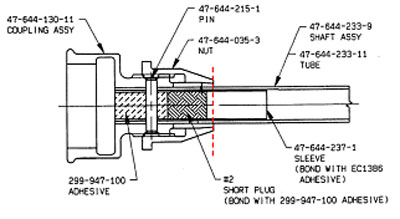
The helicopter tail rotor coupling assembly employed a tapered clamping nut arrangement bearing upon the outer circumference of the shaft tube. For rigidity in the clamped locations, an internal sleeve was fitted and secured with adhesive injected between the sleeve and tube bore.  A single machine pin passed transversely through the coupling, tube and sleeve to provide for the positive positional security of the components.  Figure 11 illustrates the assembly as a sectional view.

Figure 1: Tail rotor drive shaft coupling, point of failure indicated

Diagram of part
Forward coupling and shaft fracture

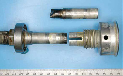
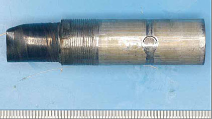
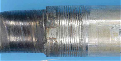
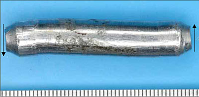
Upon initial receipt, the tail rotor drive shaft was confirmed as failed and separated at the point where it entered the forward coupling socket assembly (refer to figure 2). The fractured end of the shaft remained within the coupling, requiring removal by boring of the securing through-pin ends and pressing of the shaft stub out of the coupling (refer to figure 3).

Figure 2: Forward drive shaft coupling after disassembly

Figure 2: Forward drive shaft coupling after disassembly

Figure 3: Drive shaft stub after removal from coupling

Figure 3: Drive shaft stub after removal from coupling

The failure of the securing through-pin at both protruding ends (refer to figure 4) was evident after removal of the shaft stub. The morphology of both fractures was typical of ductile shear overload under transverse loading (shaft twisting) conditions.

Figure 4: Fractured through-pin from the forward coupling.  Note also the scoring from post-fracture rotation of the shaft

Figure 4: Fractured through-pin from the forward coupling.  Note also the scoring from post-fracture rotation of the shaft

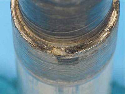
Figure 5: Spiral scoring on the gripped section of the shaft, adjacent to the fracture

Figure 5: Spiral scoring on the gripped section of the shaft, adjacent to the fracture

Circumferential scoring of the shaft surfaces to either side of the through-pin indicated subsequent rotation of the shaft inside the coupling after separation. The shaft had fractured approximately 48 mm from the coupling end, exposing the end 18mm of the internal reinforcing sleeve. The last 12 mm of the shaft before the fracture showed deep spiral scoring where the tapered grip segments normally clamped upon the surface (refer to figure 5). The shaft fracture surfaces had been marred and damaged by continuing contact after separation and presented no appreciable evidence of the failure mode (refer to figure 6).

Figure 6: Damaged shaft fracture surface

Figure 6: Damaged shaft fracture surface

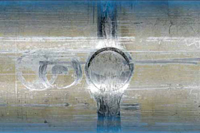
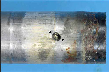
Figure 7: Torsional distortion of the drive shaft adjacent to the point of failure. Note the elongation of the small hole

Figure 7: Torsional distortion of the drive shaft adjacent to the point of failure. Note the elongation of the small hole

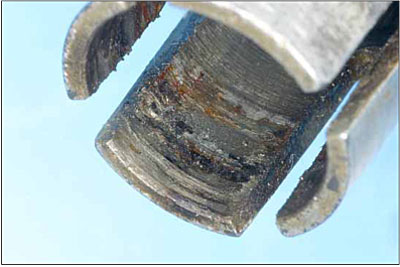
The opposing fracture and section of the shaft that extended from the forward coupling (refer to figure 7) showed extensive scoring, discolouration and galling, consistent with the damage noted inside the taper coupling bore (refer to figure 8). The examination also noted the torsional distortion of the material around a small adhesive bleed hole in the shaft wall (refer to figure 7 also). In a similar manner to the opposing section, the fracture surface had been heavily damaged by post-failure interference and presented little information of value.

Figure 8: Extensive galling and metal adhesion inside the clamping section of the forward coupling

Figure 8: Extensive galling and metal adhesion inside the clamping section of the forward coupling

Rear coupling

The rear tail rotor drive shaft coupling was a similar design to the forward unit.  The rear coupling showed no significant evidence of slippage of the shaft within the clamped section. The securing through-pin had not failed, however upon removal it presented with appreciable opposing axial bending around the points where the pin passed through the assembly (refer to figure 9).

Figure 9: Through-pin removed from the rear coupling, showing axial distortion typical of a significant torsional overload

Figure 9: Through-pin removed from the rear coupling, showing axial distortion typical of a significant torsional overload

2 ANALYSIS

The ATSB examination confirmed the failure and separation of the tail rotor shaft at the point of engagement with the forward drive coupling, approximately 48 mm from the forward end of the shaft.  While the shaft fracture surfaces were damaged beyond allowing any interpretation of the original failure mode, the twisting and distortion of the tube material at either side of the fracture was evidence of the shaft having sustained transient torsional overloading conditions.  Similarly, the shear failure of the coupling through-pin and the subsequent shaft rotation inside the coupling was a further indication that the assembly had carried, or sustained torsional loads of a magnitude well above the design allowable limits.  Mirroring the torsional overload along the load path was the distorted through-pin from the rear coupling.
On the basis of the damage sustained by the forward coupling and engaged shaft, it was evident that the failure had proceeded in two distinct stages.  Initially, the transient torsional overload event had overcome the clamping friction and caused the shear failure of the through-pin on the forward coupling.  Once the pin had failed, the shaft was then able to slip and rotate within the coupling, where it was likely that the galling damage generated between the coupling bore and shaft surface led to the 'screwing' action that pulled the shaft further into the coupling and produced the surface damage that ultimately led to the shaft fracture at that point.  While the fracture surfaces were damaged, it was probable that the shaft fracture mode was one of ductile torsional shear.  The transverse plane of fracture supports this.

Contributory events

During normal flight and ground operation, the helicopter tail rotor shaft should not sustain any transient torsional loads beyond those imposed by normal engine power changes and/or tail rotor pitch movements.  To produce the overload failure and damage to the coupling pins, the tail rotor system must have at some time, been exposed to conditions or events capable of producing a significant increase in the rotational resistance of the assembly.  Gross mechanical failures within the tail rotor gearbox, tail rotor impacts, or drive shaft bearing seizures remain as possibilities in that regard.
The reported loss of tail rotor effectiveness and the absence of rotational damage to the tail rotor upon ground impact was consistent with the drive shaft coupling slippage and rotation developing during the landing approach.  While the coupling pin failure must have been a precursor to the slippage, there was no physical or reported evidence to suggest when that failure may have occurred or what events may have contributed to it.

3 CONCLUSIONS

On the basis of the investigation findings, the following conclusions could be drawn:

  1. The helicopter tail rotor drive shaft had sustained damage consistent with a significant torsional overload event and subsequent rotational slippage and separation of the shaft at the forward coupling.
  2. The accident scenario and damage sustained was consistent with the slippage and separation of the shaft during the helicopter's landing approach.
  3. The factors contributing to the initial overload event could not be conclusively established.
  1. Diagram provided by Kawasaki Heavy Industries Ltd, assembly reference 47-640-052-39 (Shaft Assembly)

Analysis

ANALYSIS

The circumstances of the accident were consistent with a loss of tail rotor thrust following the failure of the tail rotor drive shaft as the helicopter entered the hover.

The time at which the damage to the drive shaft occurred was not able to be determined. However, given the absence of rotational damage to the tail rotor blades, it is unlikely that it occurred during the accident flight.

The action of the pilot in increasing engine power when faced with the loss of tail rotor thrust was inappropriate and exacerbated the situation.

Factual information

FACTUAL INFORMATION

At 1215 Eastern Standard Time1 on 27 September 2004, a Kawasaki Heavy Industries, 47G3B-KH42 helicopter, registered VH-MTF, was being operated on a tourist flight with one adult and a young boy as passengers. The flight included landing on a 1 m high wooden platform in the Teepookana Forest in north-west Tasmania.

The pilot reported that as he brought the helicopter to a 1 m hover above the platform, the helicopter began to rotate slowly to the right. He unsuccessfully attempted to counter the rotation by applying left tail rotor control input. The pilot then increased engine power in an attempt to regain tail rotor control and to move the helicopter clear of the landing platform. That action had the effect of rapidly increasing the rotation of the helicopter to the right and it began to ascend, reaching about 5 m above ground level. The pilot then lowered the collective control and the helicopter impacted the ground heavily on its right side, several metres from the landing platform. The pilot and adult passenger released their seatbelts and then both assisted the young boy to exit the wreckage. The pilot and passengers received minor injuries.

The pilot described the wind conditions at the time of the accident as a headwind with an approximate strength of 8 kts. That assessment was consistent with the wind data for the Strahan area provided by the Bureau of Meteorology3. The pilot also reported that the main rotor RPM indications were normal and that the helicopter had sufficient power to complete the approach4. At the time of the accident, the weight and balance of the helicopter were within prescribed limits. There was no evidence that the helicopter had collided with anything during the approach.

The pilot was appropriately qualified and endorsed to operate the helicopter type and held a valid medical certificate. He was a very experienced agricultural aeroplane pilot and had obtained a commercial pilot (helicopter) licence 14 months before the accident. He had accrued at total of 292 hours in helicopters since that time; 286.4 hours of which had been in the Bell 47 helicopter type. The pilot was experienced with operations into and out of the Teepookana Forest landing platform.

The landing platform was located within a dense forest in an area that was cleared of trees but covered by 1 m high scrub. The trees closest to the clearing had been trimmed to a height of about 5 m to allow a 'fly-in, fly-out' approach. There was no requirement to conduct a vertical approach to the platform.

The helicopter's fuselage structure was deformed by the impact and the tail boom was bent in a downward direction at approximately station 1005. There was corresponding bending damage to the tail rotor drive shaft assembly long shaft at the same point. The operator reported that examination of the damaged tail rotor pitch control system revealed that the controls were intact and would have been capable of normal operation. All parts of the helicopter were accounted for by the operator at the accident site.

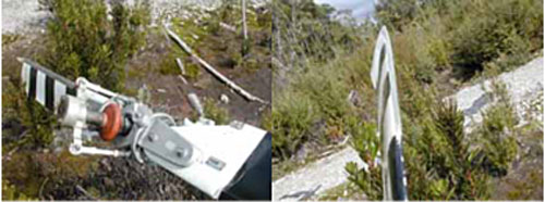
The two-blade tail rotor assembly, mounted on the right side of the tail boom, was intact and correctly attached to the helicopter. There was no evidence of rotational damage to the leading edges or tips of either blade (Figure 1). During the ground impact one blade had been bent outward at the tip and the other was bent in toward the tail rotor gearbox.

Figure 1:     Tail rotor blade damage

Wreckage


The helicopter's tail rotor drive shaft assembly consisted of a series of two short shafts and one long shaft that were situated on the top of the tail boom assembly. The long shaft was supported in eight hanger bearing assemblies and was secured at its front and rear by drive coupling assemblies. The operator inspected the tail rotor drive system and found that the long shaft assembly tubing was fractured and the pin situated through the front drive coupling assembly was sheared. There was also significant distortion of the corresponding pin in the shaft's rear coupling.

Inspection of the tail rotor drive system, including the drive shaft bearings, tail rotor extension housing and tail rotor gearbox, with the exception of the long drive shaft, revealed nothing that would have prevented normal operation.

ATSB specialist examination of the failed components (Appendix A) attributed the tail rotor drive shaft failure to a significant torsional overload event, leading to a loss of coupling security and the subsequent slippage, frictional heating and shear fracture of the shaft. That examination was unable to determine when the torsional overload occurred or what specific events may have contributed to it.

At the time of the accident, the helicopter had logged 72 flight hours since the issue of the current maintenance release. The last recorded maintenance carried out on the helicopter was a spark plug change on 21 September 2004, 1.0 flight hour prior to the accident. On 31 August 2004, 5.7 flight hours prior to the accident, one tail rotor blade was replaced because of delamination of the leading edge wear strip.

Information received from the operator and from the maintenance organisation indicated that there had been no known tail rotor strike or sudden rotor stoppage since the helicopter was placed on the Australian aircraft register in 1992. The helicopter's prior history was not examined.

The company operations manual contained the published normal and emergency procedures affecting aircraft operations. An appendix to the manual contained the flight check systems and operating procedures specific to each aircraft type operated by the company, with the exception of the Kawasaki-Bell 47G3B-KH4 helicopter. The company did however, make available to pilots a copy of the Civil Aviation Safety Authority approved Kawasaki-Bell 47G3B-KH4 helicopter flight manual.

With reference to tail rotor failures, that flight manual stipulated:

  1. Immediately execute an autorotative descent and maintain an airspeed of 34 KIAS at least.
  2. Execute a normal autorotative descent and landing.

The flight manual did not contain any specific advice for pilots in response to a tail rotor drive failure when hovering.

Information in the company operations manual regarding pilot response to a tail rotor drive failure in another piston-engine helicopter (Robinson R44) included:

LOSS OF TAIL ROTOR THRUST DURING HOVER

  1. Failure is usually indicated by right yaw which cannot be stopped by applying left pedal.
  2. Immediately roll throttle off into detent spring and allow aircraft to settle.
  3. Raise collective just before touchdown to cushion landing

The generally accepted procedure for pilot actions in the event of a tail rotor failure is to quickly roll off the throttle or snap close the throttle and perform a hovering autorotation6,7,8,9 For example:

The likely worst place for loss of tail rotor thrust to happen is in the hover, and the reaction is quite simple - get rid of the engine power and land the helicopter from a hovering engine failure condition. Easy to do on those machines that have throttle(s) on the collective10.

  1. The 24-hour clock is used in this report to describe the local time of day, Eastern Standard Time (EST), as particular events occurred. Eastern Standard Time was Coordinated Universal Time (UTC) + 10 hours.
  2. The Kawasaki Heavy Industries, 47G3B-KH4 helicopter is a single pilot/single flight control helicopter manufactured under licence from Bell Helicopters. It is commonly known as the KH4 helicopter and is a derivative of the Bell 47.
  3. Given that the pilot positioned the helicopter into wind during the approach and landing, the risk of loss of tail rotor effectiveness (LTE) was negligible.
  4. There were no external conditions that would have placed the pilot at risk of overpitching or drooping the main rotor.
  5. Positioned 100 inches aft of the datum. The datum was located 2 inches forward of the rotor mast centre-line.
  6. Coyle, S. (2003). Cyclic & collective - More art and science of flying helicopters. Mojave, CA: Helobooks, pages 341and 342.
  7. Federal Aviation Administration. (2000). Rotorcraft flying handbook (FAA-H-8083-21).  Washington, DC: FAA.
  8. Newman, R. (1999). Helicopters will take you anywhere: A manual for helicopter pilots. Mentone, Vic: The Helicopter Book Company.
  9. Becker, M. (1997). Mike Becker's helicopter handbook. Noosaville, QLD: Becker Helicopters Australia.
  10. The Kawasaki-Bell 47G3B-KH4 helicopter had a throttle of this design.

Summary

At 1215 Eastern Standard Time on 27 September 2004, the pilot of a Kawasaki Heavy Industries, 47G3B-KH4 helicopter, registered VH-MTF, was being operated on a tourist flight with two passengers in north-west Tasmania. The pilot reported that as he brought the helicopter to a 1 m hover above the raised landing platform, the helicopter began to rotate slowly to the right. The pilot unsuccessfully attempted to counter the rotation by applying left tail rotor control input. The pilot then increased engine power, however, that action had the effect of rapidly increasing the rotation of the helicopter to the right and the helicopter climbed to about 5 m above the ground. After the pilot lowered the collective control, the helicopter impacted the ground heavily on its right side. The pilot and passengers received minor injuries.

The helicopter's tail rotor drive shaft had failed during the occurrence. ATSB specialist examination of the failed drive shaft, attributed the failure to damage from a significant torsional overload event, leading to the shear fracture of the shaft. The examination was unable to determine when the torsional overload occurred, however, examination of the wreckage indicated that it was likely that it had occurred prior to this accident

Information received from the operator and from the maintenance organisation indicated that there had been no known tail rotor strike or sudden rotor stoppage since the helicopter was placed on the Australian aircraft register in 1992. The helicopter's history prior to that time was not examined.

The action of the pilot in increasing engine power when faced with the loss of tail rotor thrust was also examined.

Occurrence summary

Investigation number 200403651
Occurrence date 27/09/2004
Location 11 km NE Strahan
State Tasmania
Report release date 28/06/2006
Report status Final
Investigation type Occurrence Investigation
Investigation phase Final report: Dissemination
Investigation status Completed
Mode of transport Aviation
Aviation occurrence category Propeller/rotor malfunction
Occurrence class Accident
Highest injury level None

Aircraft details

Manufacturer Kawasaki Heavy Industries
Model 47
Registration VH-MTF
Sector Helicopter
Operation type Charter
Damage Nil

British Aerospace Plc 3201, VH-OAE

Safety Action

Safety Action

Following this and the other recent post SB A72-2087 bull gear failures, the following safety actions have been taken:

Engine Manufacturer

The manufacturer has re-assessed the SOAP procedures in Alert SB TPE 331-A79-0034 and has provided additional training to their team reviewing that data, to ensure that the guidelines are properly understood and more conservatively applied.

In August 2004, the manufacturer released Alert SB, SB TPE 331-A72-21146. That SB was a warning to operators and stated:

WARNING:

FAILURE TO COMPLY WITH THIS SERVICE BULLETIN COULD RESULT IN DISTRESS OF THE BULL GEAR, THE HIGH SPEED PINION TORQUE SHAFT, OR THE HIGH SPEED PINION COUPLER. IF LEFT UNCORRECTED, THIS DISTRESS COULD RESULT IN EITHER ENGINE SURGE OR OVERSPEED, OR COULD RESULT IN AN IN-FLIGHT SHUTDOWN. ADDITIONALLY, FRAGMENTS OF THE BULL GEAR COULD EXIT THE GEARBOX AND BE STRUCK BY THE PROPELLER. ON RIGHT HAND ENGINE INSTALLATIONS, THESE FRAG¬MENTS MAY BE REDIRECTED AGAINST THE AIRCRAFT FUSELAGE WITH SUFFICIENT FORCE TO CAUSE FUSELAGE PENETRATION AND COULD RESULT IN SERIOUS INJURY OR DEATH TO PERSONNEL AND POSSIBLE LOSS OF THE AIRCRAFT.

The SB provided the authorisation and instructions for the rework and or replacement of the Intermediate Housing and Gear (Diaphragm) Assembly part number 3102593-7, with assembly part numbers 3102593-12 or 3107191-4. Those housings contain newly designed helical pinion and bull gears, pinion gear bearings, torque shaft assembly and lubrication components. Helical gear teeth lie along a helix at an angle to the shaft7. The SB also stressed that priority be given to incorporation of the bulletin on an engine positioned on the right of an aircraft, due to the possibility of gearbox debris striking the fuselage in the event of a failure.

Civil Aviation Safety Authority

In December 2004, CASA issued Airworthiness Directive (AD) AD/TPE 331/628. That AD superseded AD/TPE 331/55 Amdt 3, 57 Amdt 1 and 58 Amdt 2. The CASA AD/TPE 331/62 incorporated the requirements of SB TPE331-A79-0034, SB TPE 331-A72-2087 and the associated Rework SB's, with the requirements of SB TPE 331-A72-2114.
The background statement for the AD indicated, in part:

This directive provides an alternative to mandatory requirements by approving the use of the manufacturer's referenced service bulletins as an alternative to both compliance times given and the requirement to replace certain parts with other parts for certain model engines. The fitment of the new designed parts will provide terminating action for the repetitive inspections detailed in this Directive.

Operator

As a result of an internal investigation into this occurrence, that involved contact with other operators in Europe and the United States who have experienced similar failures, the operator instigated a seating allocation limitation in their Jetstream aircraft. That limitation was highlighted to crews by a safety memorandum and by a company standardisation directive, dated 1 December 2004.
The memorandum stated the following:

In response to a recent service bulletin from Honeywell, seats [in] Row 1 on BAe32 [Jetstream] aircraft are only to be occupied under the following circumstances:

• Where the number of passengers is 16 or more and the seat is required for a passenger.
• Where there is an operational requirement for operational personnel to occupy a seat in Row 1 such as training and checking or auditing.
• Where directed by the captain (such as a surveillance flight by a CASA Safety Auditor).

This measure will further reduce the risks associated with potential bull gear failure on the TPE 331 [engined] aircraft.

6. Honeywell Service Bulletin - TPE 331-A72-2114 - ENGINE - REDUCTION GEAR AND SHAFT SECTION - REPLACE GEARSHAFT (SUN AND BULL GEAR) ASSEMBLY, PART NO. 3107037-9/-10, 3107122-1, 3107162-1, 3108222-1, OR 3108294-1 WITH PART NO. 3108384-1, issued 20 Aug 04.

7.ASM International, Materials Information Society Handbook, Volume II.

8. AD/TPE 331/62 has been amended to AD/TPE 331/62 Amdt 1, effective from 4 August 2005. This amendment includes provision for an alternative means of compliance for TPE 331 engines fitted to CASA 212 aeroplanes. There has been no other change to the AD. At the time of drafting the original AD the [engine] manufacturer had not provided CASA with documents detailing the AMOC [Alternative Means of Compliance].

Analysis

Analysis

The investigation determined that the bull gear failed as a result of a previously known high cycle fatigue cracking mechanism.

The Civil Aviation Safety Authority Airworthiness Directive (AD) requiring compliance with the manufacturer's Service Bulletin (SB) A72-2087 had been completed on the engine. However, the bull gear failed at less than half of the manufacturer's projected component life.

The diaphragm housing had been extensively damaged following the release of the section of the bull gear rim. That damage had prevented the investigation determining the housing's pre-failure condition and whether its condition had contributed to the failure.

At the time of the failure, the spectrometric oil and filter analysis program (SOAP) analysis had been carried out and assessed in accordance with the manufacturer's procedures. While the filter weight increases noted in the engine on 3 February 2004 and 1 April 2004 were within the manufacturer's 'normal sample' range, the above average filter weight, coupled with the traces of carbon steel may have been an indicator of the impending bull gear failure.

The crew handled the engine failure appropriately in accordance with the operator's procedures. The report of smoke in the cabin of the aircraft during the failure was consistent with the ingestion of engine oil into the compressor assembly immediately following the uncontained failure.

Factual Information

Factual Information

At 1100 Central Standard Time on 16 April 2004, a British Aerospace Plc, J32, Jetstream aircraft registered VH-OAE, with 2 pilots and 19 passengers on board, was on descent, during a scheduled passenger flight from Melbourne, Victoria to Mount Gambier, South Australia. As the aircraft passed through flight level (FL) 140, approximately 37 NM from Mt Gambier, the crew reported hearing a bang from the right engine. Simultaneously, the aircraft yawed to the right and they heard something impact the right side of the fuselage. Some smoke was evident in the cockpit.

A check of the aircraft's engine instruments confirmed a problem with the right engine and the crew shut down the engine and feathered the right propeller in accordance with the operator's quick reference handbook drills. The crew then advised air traffic control of the situation and continued for a landing at Mount Gambier Airport.

An inspection of the aircraft by the operator revealed that there had been an uncontained failure of the propeller reduction gearbox on the right TPE 331-12UHR-702H turboprop engine, serial number P66338C. There was also evidence of impact damage on the right side of the fuselage, below the co-pilot's side window area. That impact had not breached the aircraft's pressure hull.

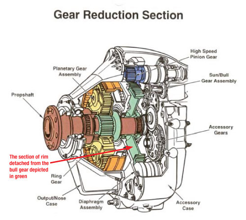
An examination of the engine, supervised by the Australian Transport Safety Bureau (ATSB), found that a section of the spur gear teeth from the outer rim of the reduction gearbox bull gear, had detached during engine operation (See Figure 1). Spur gear teeth are radial, uniformly spaced around the gear's outer periphery and parallel to the shaft axis1. The detached section of gear had penetrated the diaphragm housing (intermediate gearbox housing) and the gearbox accessory case, before exiting the engine through the compressor air intake.

Figure 1: Cutaway diagram of TPE 331 reduction gearbox

aair200401353_001.jpg


The hole in the accessory case had allowed engine oil to escape and flow over the engine cowling, with metallic debris and oil entering the engine's compressor intake. Once inside the compressor, the oil was able to enter the aircraft's compressor bleed air system that supplied the aircraft's air conditioning and pressurisation air. There was also significant associated damage to the diaphragm housing, the high speed pinion and compressor/turbine main shaft, with metallisation2 observed on the turbine and exhaust sections.

An ATSB Technical Analysis report (Appendix A), on the mode of failure of the bull gear, part number 3108295-1, found that the gear had failed as a result of a mechanism known to the manufacturer. The report indicated that the progressive propagation of high cycle fatigue cracking within the gear web and rim transition region, had caused a section of the gear rim to separate from the gear.

The engine manufacturer had introduced several changes to the bull gear design to address 'reliability and reparability issues' that had occurred in the TPE 331 engine type. Among those were changes in gear relief, gear tooth roots had been ground and shot peened to improve fatigue life, the gear rim inside diameter was shot peened to increase fatigue resistance and a coating was added to the gear web to dampen gear vibrations. The engine manufacturer reported that despite those actions some of the re-worked and coated gears had a higher failure rate than non-reworked gears.

The engine manufacturer also investigated TPE 331 engine diaphragm housings, in which gears had failed, to ascertain if distortion of the housing could cause bull gear to pinion gear misalignment. Several problems were identified with those housings that may have contributed to the gear failures. These included bull gear to pinion gear centreline growth and misalignment, growth between diaphragm to gearbox alignment pins and out-of-round bearing bores.

In October 2001, the engine manufacturer issued Service Bulletin (SB) A72-20873 in response to 16 in-service bull gear rim separations and 13 high speed pinion torque shaft failures. Four of those failures resulted in gearbox debris being ejected from the engine. One failure resulted in the penetration of the right side of an aircraft's pressure hull by a gear fragment. The bulletin indicated that high tooth loading on the bull gear to high speed pinion mesh, bull gear tooth profile, and distortion of the intermediate gearbox housings, had resulted in abnormal wear and subsequent failure of the assemblies.

Service Bulletin A72-2087 required replacement of the bull gear and high speed pinion with new, zero-time components, at intervals not to exceed 3,600 hours in service. It also required the inspection and the rework/overhaul of some gearbox components such as the diaphragm housing, plus a more stringent periodic inspection of specified gearbox components to ensure an optimum operating environment for the bull gear. At the time of failure, the bull gear assembly in this engine had accrued 1,199.55 hours and 1,523 cycles since installation. The engine had accrued a total of 10,755.7 hours and 12,295 cycles since new.

In Australia, the Civil Aviation Safety Authority (CASA) issued Airworthiness Directive (AD) AD/TPE 331/57 to require compliance with SB A72-2087. That AD became effective on 31 October 2001. Amendment 1 to that AD was issued in January 2002. The AD actions had been incorporated into the occurrence engine at the manufacturer's German maintenance facility on 20 December 2002.

Information received from the engine manufacturer following this occurrence, indicated that there had been three bull gear failures in post SB A72-2087 engines. One of those failures was the subject of a UK Air Accidents Investigation Branch (AAIB) investigation, published in AAIB Bulletin number 7/2005. Information from the AAIB on that failure indicated that the bull gear had failed in a similar manner to the gear in this occurrence.

The engine manufacturer reported that a spectrometric oil and filter analysis program (SOAP)4 was used to monitor an engine's in-service condition and to reduce the possibility of a premature mechanical failure. That program monitored the type and quantity of the deposits in the engine oil and oil filters over a specified period. A trending feature within that program could highlight an engine with a rapidly increasing filter 'weight' and indicate that further maintenance action was required. A high filter weight quantity of Carbon Steel in a sample could indicate a problem with the bull gear assembly. In November 2000, the engine manufacturer issued Alert Service Bulletin TPE 331-A79-00345 that changed the SOAP interval periodicity to a fixed 100+/- 20 engine hours to minimise variability. On 25 January 2001, CASA issued AD/TPE 331/55 that required Australian compliance with that Alert SB.

The operator had complied with the engine manufacturer's and CASA's SOAP requirements, forwarding samples to the manufacturer's approved venue for testing. The operator reported that they had become concerned about a SOAP report for the occurrence engine that had been received on 3 February 2004. That report, although still within the manufacturer's 'normal sample' guidelines, had a significantly higher filter weight result than had been previously noted for the engine. When queried, the manufacturer confirmed the results of the sample and indicated that a higher reading may be seen following an engine oil change. The engine oil had been changed 101 engine hours prior to that sample being taken. In the subsequent SOAP sample taken 60 engine hours later, on 24 February 2004, the filter weight had returned to a similar level to that of the pre-3 February 2004 samples. The final sample taken prior to the occurrence, on 1 April 2004, was higher than usual and all of the samples had traces of carbon steel.

1. ASM International, Materials Information Society Handbook, Volume II.

2. Metal pulverised by the compressor becomes molten or burned in the combustion chamber and flows rearward, attaching to the turbine and exhaust assemblies (US Department of the Air Force.(1987). Safety Investigative Techniques (AF Pamphlet 127-1, Volume II). Washington DC: Author).

3. Honeywell Alert Service Bulletin - TPE 331-A72-2087, ENGINE - REDUCTION GEAR AND SHAFT SECTION - Replace Gearshaft (Sun and Bull Gear) Assembly, Part No. 3107037-9/10, 3107122-1, 3107162-1, or 3108222-1, or 3108294-1 with Part No. 3108294-1, issued October 2001 and revised 16 November 2001.

4.Service Information Letter - P331-97 - THE HONEYWELL SPECTROMETRIC OIL AND FILTER ANALYSIS PROGRAM FOR ALL TPE 331 ENGINES EXCEPT -14GR/HR ENGINES; Revision 10, Apr 5/02.

5. Honeywell Alert Service Bulletin - TPE 331-A79-0034 - OIL DISTRIBUTION - DECREASED TIME INTERVAL BETWEEN SPECTROMETRIC OIL (AND FILTER) ANALYSIS PROGRAM (SOAP) SAMPLING; Revision 4, Apr 5/02.

Summary

At 1100 Central Standard Time on 16 April 2004, a British Aerospace Plc, J32, Jetstream aircraft registered VH-OAE, with 2 pilots and 19 passengers on board, was on descent, during a scheduled passenger flight from Melbourne, Victoria to Mount Gambier, South Australia. As the aircraft passed through flight level (FL) 140, approximately 37 NM from Mt Gambier, the crew reported hearing a bang from the right engine. Simultaneously, the aircraft yawed to the right and they heard something impact the right side of the fuselage. Some smoke was evident in the cockpit.

Occurrence summary

Investigation number 200401353
Occurrence date 16/04/2004
Location 65 km E Mount Gambier, (VOR)
Report release date 20/01/2006
Report status Final
Investigation type Occurrence Investigation
Investigation status Completed
Mode of transport Aviation
Aviation occurrence category Propeller/rotor malfunction
Occurrence class Serious Incident
Highest injury level None

Aircraft details

Manufacturer British Aerospace
Model 3200
Registration VH-OAE
Serial number 851
Sector Turboprop
Operation type Air Transport Low Capacity
Damage Nil

de Havilland Canada DHC-8-314, VH-TQA

Summary

Sequence of events

On 30 November 2003, a de Havilland Canada DHC-8 (Dash 8) aircraft, registered VH-TQA, departed Sydney, NSW, on a scheduled passenger flight to Albury, NSW. Shortly after take-off, a passenger reported damage to the lower area of the window on the left side of the aircraft, at row five. After confirming the damage, the flight crew returned the aircraft to Sydney, where an inspection revealed that a propeller blade collar had separated from one of the blades of the left propeller (refer figure 1). A small piece of the separated collar, with one attaching bolt and nut, was subsequently retrieved adjacent to the departure runway (refer figure 2).

An engineering examination of the left propeller revealed that a blade collar had separated from one propeller blade. As one other propeller blade sustained damage from the collar separation, both were sent to an overhaul facility in New Zealand for examination under the supervision of the New Zealand Transport Accident Investigation Commission (TAIC).

In December 2002, a major inspection was completed on the propeller blade from which the collar had separated. In June 2003, it had undergone a trailing edge repair, due to impact damage. The blade collar was bonded to the blade root with sealant compound RTV-157, and the collar halves were also fastened by two connecting bolts, nuts and associated washers. The single recovered bolt, nut and washers were found intact with no apparent damage.

An examination of the sealant compound on the recovered section of the collar revealed that the sealant used was the correct type and specification and within its time and life expiration dates. A detailed examination of the recovered collar piece at the ATSB revealed that the collar displayed no gross manufacturing defects, but that the bonded joint gap was large and that no effective bonding had occurred on the mating surface. There was also evidence of sealant compound having been applied as a thin layer at a previous time. This film of sealant was partially covered by black paint.

A small sample of recovered RTV157 sealant was sent to a specialist laboratory for examination and comparison with a known reference sample. That examination indicated that the sealant recovered from the failed propeller blade cuff had been contaminated with a black substance giving it a different appearance from the supplied reference sample. The failed RTV 157 also contained a significant proportion of an extractable ester-based chemical that was not detected in the reference compound.

A review of the laboratory findings by the propeller manufacturer, relating to the RTV 157 compound, indicated that there were a number of potential sources of sealant contamination during assembly, installation, and operation of the propeller. However, there was not enough evidence to indicate the source of the observed contamination.

Subsequent to this occurrence, on 28 October 2004 a collar separated from the propeller of another of the operator's Dash 8 aircraft. In this instance, the collar did not impact the aircraft and was noticed missing during a subsequent pre-flight inspection. That collar had also been bonded with RTV-157 sealant.

As the entire blade collar was not recovered, a full assessment of the collar failure was not possible and factors relating to the assembly geometry of the collar could not be assessed.

As a result of the occurrence, the aircraft operator immediately initiated an inspection program of all similar propeller blade collars. That inspection revealed that five other aircraft had at least one loose propeller blade collar. All affected propeller blade collars were immediately repaired.

Subsequent to the initial fleet inspection, the operator initiated a repetitive inspection regime, requiring a visual inspection for condition and security of all propeller blade collars. Additionally, the operator issued an instruction to all propeller workshops servicing their propellers, requiring that all propeller blade collars are to be bonded using an approved alternate bonding compound, PR 1826.

Occurrence summary

Investigation number 200304918
Occurrence date 30/11/2003
Location Sydney, Aero.
State New South Wales
Report release date 16/12/2004
Report status Final
Investigation type Occurrence Investigation
Investigation status Completed
Mode of transport Aviation
Aviation occurrence category Propeller/rotor malfunction
Occurrence class Incident
Highest injury level None

Aircraft details

Manufacturer De Havilland Canada/De Havilland Aircraft of Canada
Model DHC-8
Registration VH-TQA
Serial number 365
Operation type Air Transport High Capacity
Departure point Sydney, NSW
Destination Albury, NSW
Damage Minor

Aerospatiale AS.332L, VH-BHY

Safety Action

Local safety action

Immediately following the incident, the helicopter operator changed the tail rotor pitch change shaft bearings in all of the AS332L helicopters in its fleet. Subsequently, the operator issued Alert Message AM/332/03/008 to all of its local and international facilities, instructing maintenance personnel to immediately change the pitch change shaft bearings should they have been contaminated by hydraulic fluid, or should any doubt exist as to the bearing's condition.

On 5 November 2003, the aircraft manufacturer issued Information Telex 00000151, alerting all operators of AS332, AS330 and AS532 aircraft of the subject incident and instructing maintenance personnel to check the tail rotor pitch change bearing if any fluid leak is discovered at the tail rotor servo actuator. Subsequently, Alert Telex 00000158 was issued on 8 December 2003 requiring 10-hourly inspections for hydraulic leaks at the tail rotor boot and detailing a new mandatory maintenance procedure to be applied should a leak be discovered. Due to an error in the original Alert Telex, an erratum document (Alert Telex 00000166) was issued on 19 December 2003.

On 26 February 2004, the Direction Gnrale de l'Aviation Civile France ( DGAC) issued airworthiness directive (AD) No. F-2004-031, mandating the 10-hourly inspection of the AS332 tail rotor hub boot for evidence of hydraulic fluid leakage. If fluid leakage is discovered, replacement of the pitch-change shaft bearing is required. The Australian Civil Aviation Safety Authority subsequently issued AD/S-PUMA/51 on 26 February 2004, mirroring the requirements of AD F-2004-031 for aircraft in the Australian fleet.

1 Right-hand thread, clockwise rotation to tighten.
2 Counter-clockwise to tighten.
3 The aircraft manufacturer identified the bearing grease as Aeroshell-33 universal airframe grease (MIL-PRF-23827C Type 1).
4 Specified as Aeroshell fluid 41 (MIL-PRF-5606H).
5 Anexus Laboratories, Bulleen Victoria. Report No. C1110 "Assessment of Bearing Grease for Possible Contamination".

Significant Factors

The following factors were identified as significant to the development of the incident.

  1. The tail rotor control servo unit developed a hydraulic fluid leak, with some of the lost fluid entering the pitch change shaft bearing space.
  2. Migration of hydraulic fluid into the bearing diluted the grease, affecting the lubricant efficacy and producing accelerated wear and break-up of the bearing cage.
  3. The bearing grease was soluble in the hydraulic fluid.
  4. The bearing was allowed to remain in service following the discovery and rectification of the hydraulic leak.
  5. The pitch change shaft inboard (servo end) nut was a conventional ( right-hand) thread, allowing it to be loosened and unscrewed by torque from the rotating tail rotor drive shaft.
  6. Disconnection of the pitch change shaft from the servo actuator caused control of the tail rotor to be lost.

Analysis

The investigation found that the loss of tail rotor control reported by the flight crew of VH-BHY occurred as a result of the disconnection of the tail rotor pitch change servo from the control rod. That disconnection was a direct result of a breakdown in the anti-friction properties of the tail rotor pitch change shaft bearing, allowing the rotational torque along the pitch change shaft to overcome the assembly torque and locking assembly of the servo end shaft nut. The rotating shaft subsequently unscrewed the nut, allowing it to drop into the tail structure from where it was recovered.

The tail rotor pitch change shaft bearing failure occurred as a result of the contamination and dilution of the grease lubricant, leading to the internal mechanical breakdown of the bearing cage and the partial seizure of the assembly. Testing showed that the bearing grease was contaminated by hydraulic fluid, which likely released from a leaking tail rotor servo-actuator unit identified and replaced 22 days before the incident. The bearing was inspected at the time of the leak discovery and was found to be satisfactory for further service. At that time, there was no requirement to change the bearing in the event of the leakage of hydraulic fluid into the bearing space.

Summary

History of the flight

At approximately 1715 on 29 August 2003, the crew of a Eurocopter AS332L 'Super Puma' helicopter, registration VH-BHY, being operated on an offshore commuter flight from Karratha, Western Australia, reported feeling a sudden airframe jolt, followed by a pitch up, roll, and a left yawing motion. Finding they had lost tail rotor control, the crew stabilised the aircraft using pitch and roll control inputs, before declaring a MAYDAY to air traffic services. After assessing the helicopter's condition and vibration levels, the crew elected to return to Karratha where a run-on landing could be performed. The MAYDAY condition was downgraded to a PAN and, after assessing the helicopter's performance during a precautionary approach, a safe run-on landing was conducted.

The aircraft was carrying a flight crew of two and six passengers who were uninjured.

Damage to the aircraft

Damage to the helicopter was limited to the tail rotor pitch change assembly and the tail boom lower keel fairing, which had pulled out several attachment screws. During the initial post-incident inspection, the operator's ground maintenance personnel found the nut and lock washer disconnected from the servo end of the pitch change rod, allowing the rod to move freely within the servo body. The nut and washer were subsequently found in the tail structure beneath the tail rotor drive shaft. The rod (P/N 332A33-0043-00) had sustained circumferential gouging and scoring around the surfaces adjacent to the inboard side of the pitch change spider bearing (P/N 330A33-9903-20). The bearing itself showed evidence of gross mechanical failure, with break-up of the ball cage and dislodgement of the outboard and inboard seals. The outboard bearing retention nut and lock washer remained in-place and secure (figure 2).

Aircraft information

Manufacturer Aerospatiale (Eurocopter)
Model AS332L 'Super Puma'
Serial Number 2129
Registration VH-BHY
Year of manufacture 1984
Total airframe hours 13,525 (approx, at time of incident)

Tail rotor assembly information

The Super Puma helicopter tail rotor control was effected by a hydraulic servo-actuator that applies control force to the tail rotor blades via a central shaft and spider assembly. A locking nut and lock washer secured the actuator to the shaft, assembled to a nominal 266 - 443 pound-inches ( 30 - 50 Newton-metres) dry torque. At the spider end, the connection was similar, with a nominal dry torque of 115 - 266 pound-inches (13 - 30 Newton-metres). The Super Puma tail rotor turns in a counter-clockwise direction when viewed from the right side of the aircraft. The securing nut on the servo end of the pitch change shaft had a conventional thread, while the nut on the spider end of the rod had a left-hand thread. Figures 3 and 4 illustrate the tail rotor assembly and pitch change shaft location.

Maintenance history

The failed tail rotor bearing was first fitted to VH-BHY in June 2000, as part of a complete replacement tail rotor gearbox (TRG) assembly. The gearbox, including bearing, had 199 hours time since overhaul (TSO) when installed. Replacement of the pitch change bearing is normally carried out during gearbox overhaul, however documentation to confirm that action was not available to the investigation.

In June 2003, maintenance action was carried out on the gearbox in response to elevated lateral vibration levels recorded by the helicopter's integrated health and usage monitoring system (IHUMS). Subsequently, on 7 August 2003, the tail servo was replaced after the discovery of leaked hydraulic fluid inside the boot between the tail rotor hub and the pitch change spider. It was evident that the fluid had travelled from the tail servo, through the tail rotor drive shaft and into the boot, bringing the fluid into close proximity with the inboard end of the tail rotor pitch change shaft bearing. The gearbox and assembly had accrued 1,888 hours TSO at that time. During the weeks following the hydraulic leak, the pitch change shaft bearing was inspected as required by service bulletin SB05-00-29 Rev. 3 and accepted for further service. At the time of failure on 29 August 2003, the TRG and pitch change shaft bearing had operated for 1,959 hours since overhaul.

Bearing failure

The bearing fitted to the tail rotor pitch change assembly on VH-BHY was a single race, fully sealed ball bearing, manufactured by SNFA, France. The bearing carried the following identifying marks:

330A33990320 8020141 SNFA FRANCE V80I24K14

ATSB laboratory examination of the bearing confirmed the mechanical failure and break-up of the bearing cage, allowing the circumferential movement of the balls relative to each other and the resultant development of abnormal race loading and frictional conditions (figure 5). The bearing internal surfaces were dry and in most places covered with an adherent black compound (figure 6) that was sampled for later analysis. There was no evidence of any viscous bearing grease remaining within the bearing confines. All rolling contact surfaces of the bearing showed bruising and particle indentation damage (figure 7), however there was no indication of spalling or other rolling contact fatigue type breakdown. None of the bearing components showed evidence of gross overheating or frictional seizure. The bearing cage showed gross levels of wear and metal loss in areas exposed to contact with the rolling elements (figure 8 ). Several fracture surfaces showed evidence of fatigue cracking. The external surfaces of the bearing outer race showed fretting corrosion and wear to the extent of seating within the pitch change spider assembly ( figure 9). There was no evidence of circumferential scoring or other indications of race rotation within the housing or on the bearing seat. Traces of light oil were found on the bearing seat. The odour and appearance of the oil were typical of hydraulic fluid.

Bearing construction

The ATSB examined the tail rotor pitch change bearings from two other AS332L helicopters maintained by the same operator. Both of those bearings and their integral seals were found to be in serviceable condition and showed none of the characteristic indications of failure presented by the bearing from VH-BHY. The service lives of both examined bearings were comparable to the failed unit from VH-BHY. A sample of grease from one of the serviceable bearings was subject to a solubility test with a small quantity of hydraulic fluid recovered from the tail rotor servo fitted to VH-BHY at the time of the incident. With a small amount of manual agitation, the grease proved miscible within the hydraulic fluid, producing a liquid with a characteristic viscosity not appreciably greater than the original hydraulic fluid. Weighing the bearing before and after cleaning found the unit carrying 1.88 grams of grease, which the aircraft manufacturer indicated was a nominal quantity.

Bearing contaminant analysis

Samples of the remnant lubricant from inside the failed bearing, the uncontaminated grease from a serviceable bearing and the hydraulic fluid from VH-BHY were forwarded to an analytical laboratory to determine whether any trace of the hydraulic fluid could be detected within the material from the failed bearing.

Results from that analysis confirmed the presence of characteristic spectral peaks from the hydraulic fluid to exist within the remnants of the grease from the failed bearing. These peaks did not exist within the sample of uncontaminated grease from the serviceable bearing.

Occurrence summary

Investigation number 200303804
Occurrence date 29/08/2003
Location North Rankin A Platform, (HLS)
State Western Australia
Report release date 24/05/2004
Report status Final
Investigation type Occurrence Investigation
Investigation status Completed
Mode of transport Aviation
Aviation occurrence category Propeller/rotor malfunction
Occurrence class Incident
Highest injury level None

Aircraft details

Manufacturer Aerospatiale Industries
Model AS332
Registration VH-BHY
Sector Helicopter
Operation type Charter
Departure point Karratha, WA
Destination North Rankin A offshore platform
Damage Minor

de Havilland Canada DHC-8-315, VH-TQY

Summary

During initial climb, the right propeller of the DHC-8-315 (Dash 8) aircraft auto-feathered. The flight crew retarded the right engine power lever, declared a PAN (radio code indicating uncertainty or alert) condition, and completed an uneventful single engine return to Sydney airport.

The aircraft was fitted with two Pratt and Whitney Canada PW123E engines. The flight data recorder (FDR) indicated that the right engine over-torqued to 120 percent for 7 seconds after the propeller feathered. The FDR also indicated that the left engine over-torqued to 117 percent for 20 seconds. The engine manufacturer's transient over-torque limits were not exceeded.

Maintenance personnel found that a loose connection of the right engine torque signal conditioning unit (TSCU) connector pins resulted in an intermittent electrical connection. The TSCU was replaced as a precaution, and the connector was cleaned and reseated. Following a flight test, the aircraft was returned to service.

Propeller auto-feathering

The propeller auto-feather system, when selected, was designed to automatically feather the propeller during take-off if the engine torque decreased below about 22 percent rated torque. Interlock features in the auto-feather logic and control circuits provided arming control and prevented auto-feather of the operating propeller, once the auto-feather sequence for one of the propellers was initiated. The system provided for relaying a 'power uptrim' (engine power increase) signal to the operating engine.

Previous occurrences

The ATSB investigation into two previous occurrences (199905044 and 200002853) determined that in the earlier occurrence the electronic engine controller electrical connector was contaminated with water, while a faulty TSCU was found in the other.

The two previous Australian occurrences were also documented on the Australian Civil Aviation Safety Authority's database. A search of the engine manufacturer's database and the Service Difficulty Databases for Transport Canada and the United States of America Federal Aviation Administration, revealed twenty-three similar occurrences in the period from 19 June 1993 to 27 October 2001.

Of the twenty-six worldwide events reported, four were confirmed in-flight engine shutdowns (IFSD). Nineteen were attributed to electrical problems (harness and/or connector or torque signal conditioning unit). Fourteen events occurred during initial climb out and ten during the take-off roll.

Aircraft and engine manufacturer background information

The aircraft manufacturer advised that their data indicated that propeller auto-feathering as described in this incident was a result of loss of torque signal to the TSCU, most likely due to "connector intermittencies". Improvements to the system included design changes to strengthen the torque signal, and flight crew procedural changes. The aircraft manufacturer considered that the present decrease in reported occurrences reflected the success of these changes.

The engine manufacturer reported that the occurrences were associated with an intermittent loss of torque signal. They recommended, when an operator experienced one or more occurrences, that the operator conduct a fleet-wide electrical harness inspection, clean the connectors and enhance connector tightening procedures.

Service bulletins and operator letters

On 25 May 1993, the engine manufacturer issued Service Bulletin (SB) 21269 addressing the application of shrink tubing to the TSCU wiring harness to provide protection from moisture ingress and loosening of the connectors.

On 19 December 1995, the engine manufacturer issued SB 21456 addressing spurious `uptrims' and activation of the auto-feather control system when the system was in the armed condition. Those problems were attributed to the torque sensor air gap not being optimised. The procedures were described for decreasing the torque sensor air gap by replacing a spacer in the unit. The modification improved signal strength and reduced sensitivity to electrical 'noise'.

On 31 January 1996, the engine manufacturer issued SB 21463 addressing fretting of the TSCU electrical connector socket pins. The modification involved replacing the existing wiring harness with one that included a more secure connector assembly with sockets less susceptible to fretting.

On 11 December 1997, the engine manufacturer issued Operator Message Number (OMN) 464 informing operators of two recent IFSD auto-feather events and advised them that those events may have been the result of incorrect tightening torque on the TSCU connectors. They recommended that the connectors be inspected for security, and if found loose, should be disconnected and inspected for contamination and moisture.

On 28 February 2000, the engine manufacturer issued OMN 602 informing operators of recent IFSD auto-feather events and reiterated procedures currently published in the Aircraft Flight Manual. The letter strongly recommended that the operator's review, with their flight crews, the correct procedures to follow with respect to any engine or propeller malfunction on take-off. The letter also noted that previous events had indicated that flight crews often retard the power levers of both engines, thereby cancelling the `power uptrim' signal to the operating engine.

Compliance with these bulletins and messages was not mandatory, however the maintenance organisation implemented the requirements of SBs 21269, 21456 and 21463.

Occurrence summary

Investigation number 200105173
Occurrence date 27/10/2001
Location Sydney, Aero.
State New South Wales
Report release date 19/12/2002
Report status Final
Investigation type Occurrence Investigation
Investigation status Completed
Mode of transport Aviation
Aviation occurrence category Propeller/rotor malfunction
Occurrence class Incident
Highest injury level None

Aircraft details

Manufacturer De Havilland Canada/De Havilland Aircraft of Canada
Model DHC-8
Registration VH-TQY
Serial number 552
Sector Turboprop
Operation type Air Transport High Capacity
Departure point Sydney, NSW
Destination Canberra, ACT
Damage Nil

Saab SF-340A, VH-KEQ

Safety Action

Local safety action

The operator reported that following the incident, they reviewed their SF340 simulator training procedures highlighting the requirement for closer monitoring of propeller RPM indications. Changes were also made to their SF340 Flight Crew Operations Manual, and the incident was featured in the company's Safety Promotion Newsletter.

Summary

The SAAB SF 340's departure from Wagga airport had been delayed for 4.5 hours due to ground fog. As the aircraft taxied for departure, the crew completed the pre-flight checks. Incorporated within these checks was the requirement for a "first flight of day" propeller governor overspeed test. As it was the aircraft's first flight for the day, the check was carried out.

Following take-off, and shortly after landing gear retraction, with the Constant Torque On Take-off system engaged, the crew noted that the right engine propeller RPM was low; at approximately 1,100 RPM. The left propeller was within the normal operating range at an indicated 1,378 RPM.

As a return to Wagga was unavailable, due to ground fog, the crew contacted air traffic control indicating their intention to divert to Albury Airport. An Alert Phase was declared and Albury Emergency Services were on stand-by for the aircraft's arrival.

The crew then carried out the appropriate abnormal checklist actions for a propeller underspeed, shutting down the right engine just prior to the top of descent. During that time, the crew briefed the cabin attendant on the engine problem, before informing the passengers of the situation via the aircraft's public address system. Following an uneventful single engine approach and landing, the Alert Phase was cancelled.

An investigation by the aircraft's operator, included analysis of the aircraft's flight data recorder readout. The analysis indicated that during taxi the right propeller RPM had reduced from 1,040 to 990. That RPM drop was consistent with the crew carrying out the propeller governor overspeed test. However, unlike the left propeller, the right propeller RPM had not fully recovered at the completion of the check.

Both crew members reported that on completion of the propeller overspeed governor checks, once they had observed the propeller indications returning towards normal, their attention was diverted towards other checks. The crew also indicated that during the take-off they did not normally check the propeller RPM indications, instead monitoring the engine parameters of "torque and inter-turbine temperature". Consequently, the low right-propeller RPM had not been initially detected.

During the take-off roll the crew noted that the right engine torque had lagged behind the left. That was considered to be due to not having the right power lever pushed far enough forward, as the Constant Torque On Take-off system only engages after advancing the power lever past 64 degrees. The crew had then pushed the right power lever further forward in order to equalise both engine torque indications.

After the flight, the operator completed a thorough maintenance check of the right engine and propeller systems. No unserviceabilities were found during that check. Following consultation with the aircraft's engine manufacturer the aircraft was returned to service. The problem did not re-occur.

The operator attempted to replicate the problem in their SAAB 340 flight simulator. That attempt was observed by a representative from the Civil Aviation Safety Authority. After thorough investigation, the operator was unable to repeat the occurrence.

Occurrence summary

Investigation number 200002644
Occurrence date 10/06/2000
Location Wagga Wagga, Aero.
State New South Wales
Report release date 20/12/2001
Report status Final
Investigation type Occurrence Investigation
Investigation status Completed
Mode of transport Aviation
Aviation occurrence category Propeller/rotor malfunction
Occurrence class Incident
Highest injury level None

Aircraft details

Manufacturer Saab Aircraft Co.
Model 340
Registration VH-KEQ
Serial number 340A-011
Sector Turboprop
Operation type Air Transport Low Capacity
Departure point Wagga Wagga, NSW
Destination Melbourne, VIC
Damage Nil