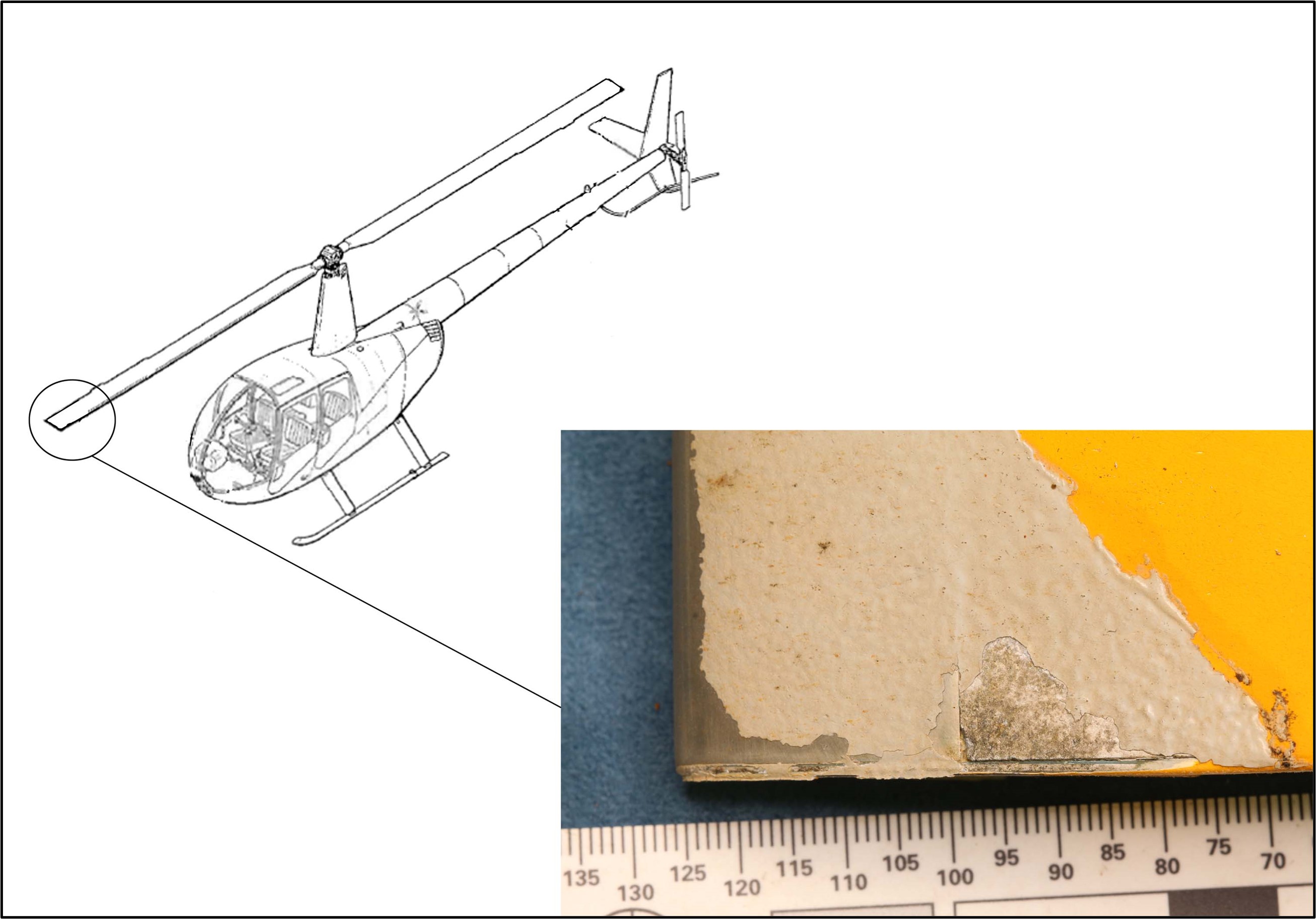
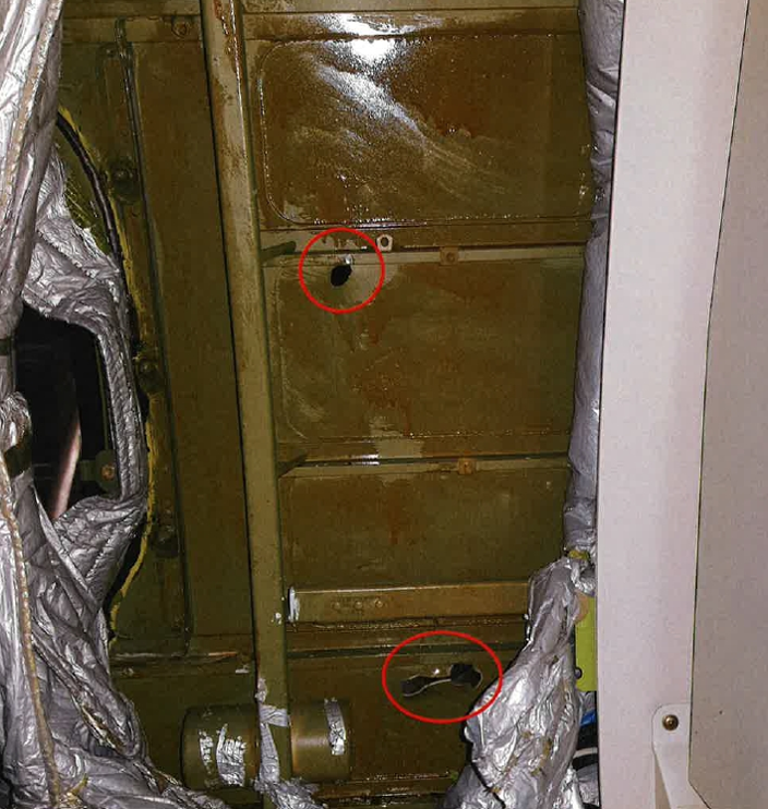
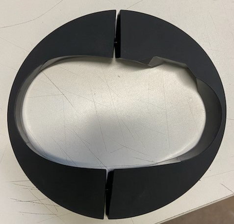
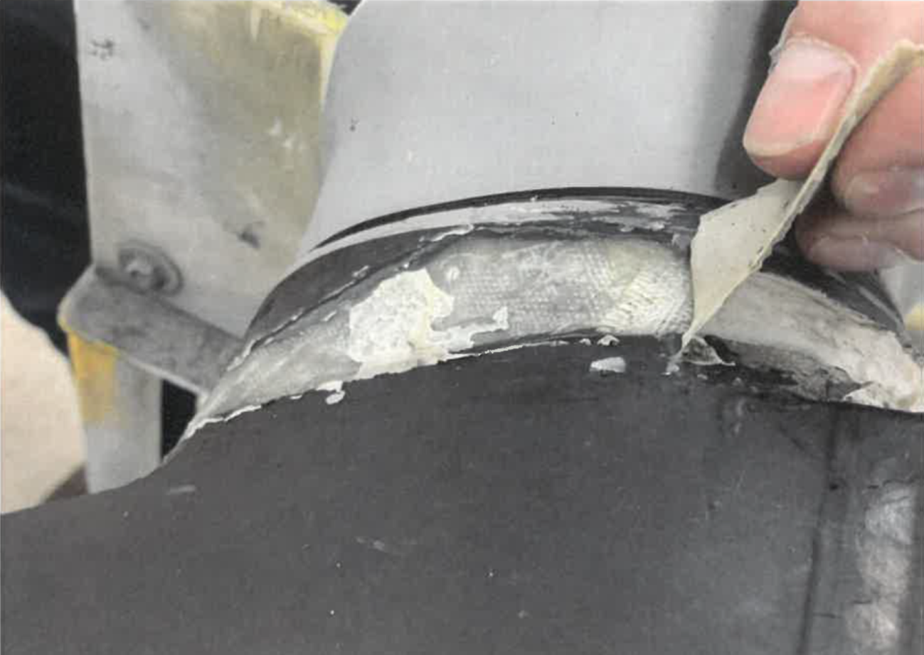
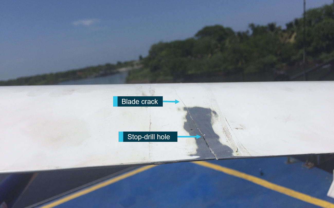
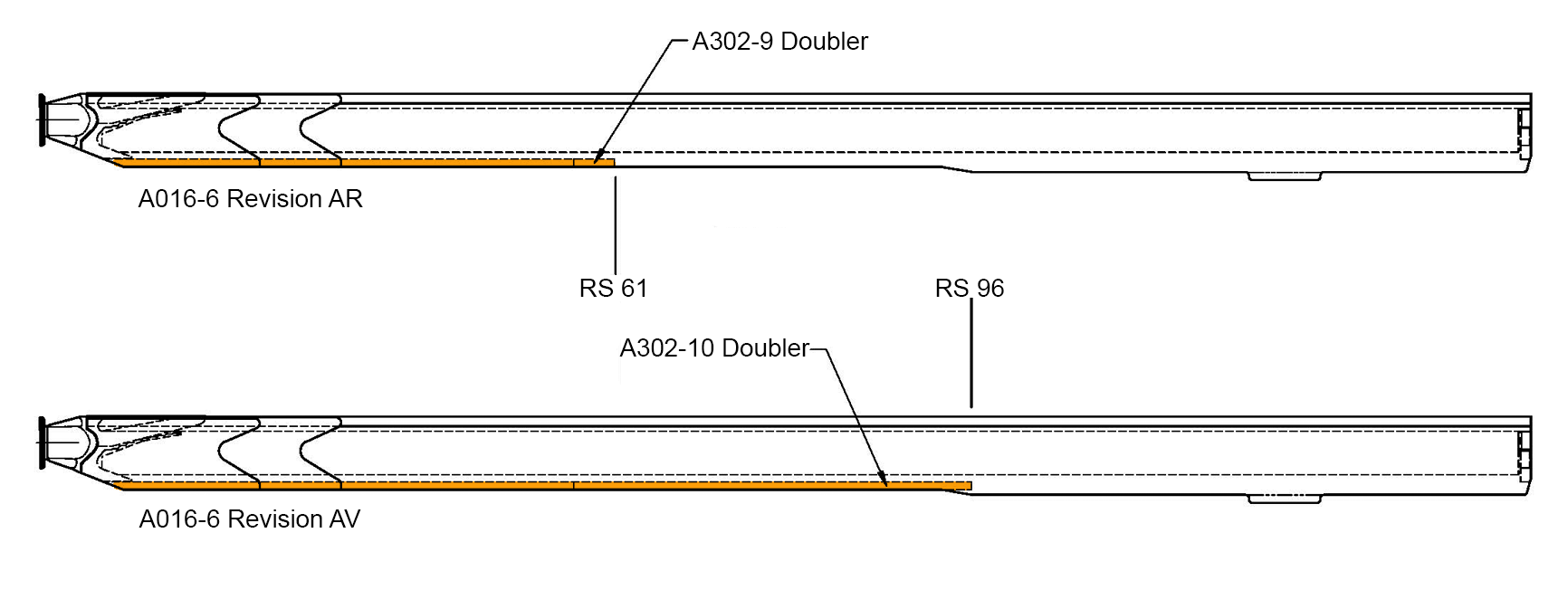
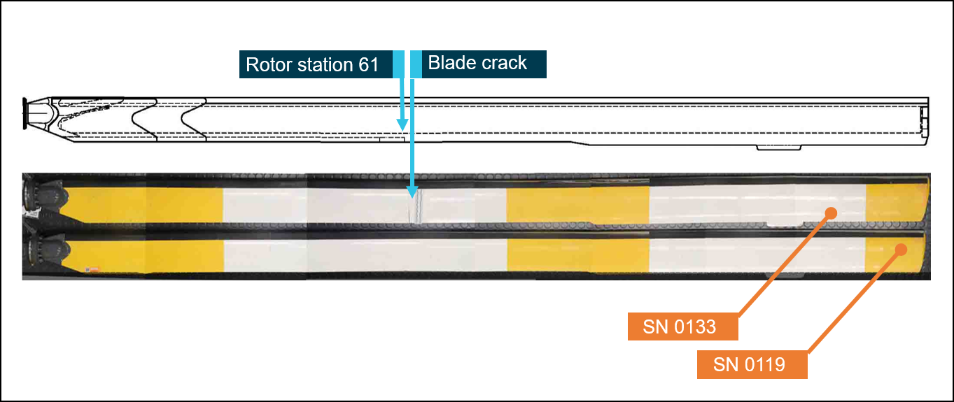
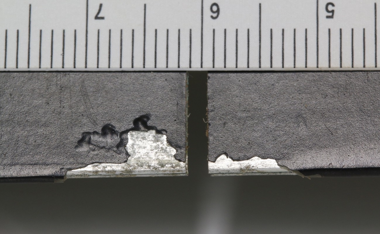
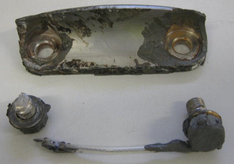
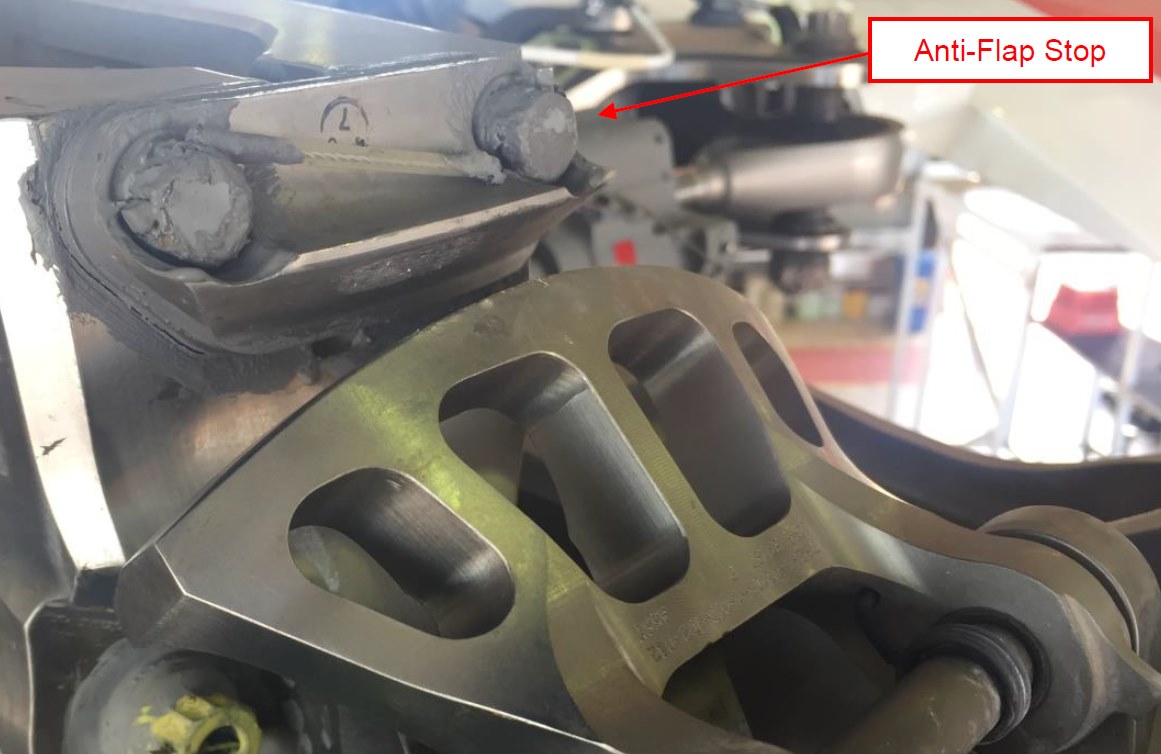
The ATSB is investigating a tail rotor failure and subsequent collision with terrain involving a Robinson R22 Beta, registered VH-UBY, about 56 km west of Coonamble Airport, New South Wales, on 6 February 2026.
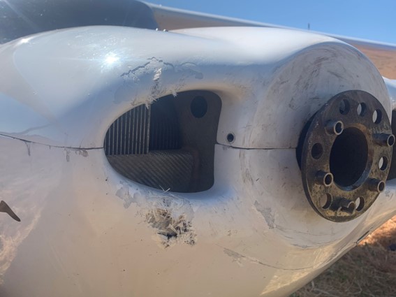
During aerial mustering operations approximately 100 ft above the ground, the pilot and sole occupant of the helicopter experienced an RPM spike followed by a yaw and a loss in rudder effectiveness. Unable to counteract the yaw, the pilot attempted to land the helicopter, which spun several times during the descent.
Upon contact with the ground, the helicopter rolled onto its side, resulting in substantial damage. The pilot experienced serious injuries, but was able to exit the helicopter without assistance. There was no fire.
The evidence collection phase of the investigation will involve examining tail rotor components, interviewing the pilot and any witnesses, examination of maintenance records, retrieving and reviewing recorded data, and the collection of other relevant information.
A final report will be released at the conclusion of the investigation. Should a critical safety issue be identified during the course of the investigation, the ATSB will immediately notify relevant parties, so that appropriate safety action can be taken.
Occurrence summary
Investigation number
AO-2026-063
Occurrence date
06/02/2026
Occurrence time and timezone
10:15 Australian Eastern Daylight Time
Location
About 56 km west of Coonamble Airport
State
New South Wales
Report status
Pending
Anticipated completion
Q3 2026
Investigation level
Short
Investigation type
Occurrence Investigation
Investigation phase
Evidence collection
Investigation status
Active
Mode of transport
Aviation
Aviation occurrence category
Abnormal engine indications, Collision with terrain, Propeller/rotor malfunction
Occurrence class
Accident
Highest injury level
Serious
Aircraft details
Manufacturer
Robinson Helicopter Co
Model
R22 Beta
Registration
VH-UBY
Serial number
4733
Aircraft operator
Dustdevil Helicopters Pty Ltd
Sector
Helicopter
Operation type
Part 138 Aerial work operations
Activity
General aviation / Recreational-Aerial work-Agricultural mustering
On 16 May 2022, a Robinson Helicopter Company (RHC) R44, registered VH-KOV and operated by Wellspring Rural Services Pty Ltd, was being used to conduct a series of sightseeing flights over the Limmen National Park, Northern Territory, with a pilot and 3 passengers on board.
During cruise flight, vibrations were detected through the helicopter, subsequently the pilot observed the engine RPM rise and then drop to zero. Having assessed that the engine had failed, the pilot initiated an autorotation and the helicopter subsequently collided with terrain. Two passengers sustained serious injuries, with the pilot and remaining passenger sustaining minor injuries. The helicopter was substantially damaged.
What the ATSB found
The ATSB found that during cruise, the clutch actuator lower bearing seized resulting in a total loss of drive from the engine to the rotor system. This bearing had not been maintained in accordance with the maintenance procedures, which likely resulted in its failure.
It was also identified that the passengers did not receive a pre-flight safety brief resulting in them being unaware of the emergency procedures and the safety equipment on the helicopter.
In December 2021, the Civil Aviation Safety Authority (CASA) released Civil Aviation Safety Regulation (CASR) Part 133, which changed the regulations related to air transport passenger carrying operations in helicopters. The ATSB found that there were several changes to the requirements which were not promulgated to operators in the documentation released to explain the regulatory changes, including the mapping of Civil Aviation Regulations to CASR Parts 91, 119 and 133–Australian air transport operations–rotorcraft and CASA Part 133 Key operational changes with suggested text.
CASR Part 133 required changes to the pre-flight passenger safety briefing for aircraft with a seating capacity of less than 6 people, including that passengers were briefed on the emergency brace position with information specific to their aircraft type and model. However, while CASA provided guidance on how to brace in some configurations, they did not provide specific information on how to brace in a helicopter, such as the R44, which has 3-point harnesses installed.
It was also identified that the emergency locator transmitter (ELT), which activated 10 hours after the accident, was not being maintained and the operator had not been advised of this.
Finally, the ATSB also found that the Robinson Helicopter maintenance procedures and CASA guidance did not provide clear guidance on how ELTs in helicopters should be maintained.
What has been done as a result
As a result of this investigation the maintainer contacted each of the operators of the helicopters they maintain to ensure they were aware that the emergency locator transmitter (ELT) was not being maintained and to ensure they were carrying a personal locator beacon in the helicopter.
The Civil Aviation Safety Authority (CASA) also updated the airworthiness bulleting (AWB) 02-002 to include information on ELT maintenance and guidance if the information contained within the aircraft’s maintenance schedule is not sufficient.
The ELT manufacturer has also advised the discrepancy between the service letter and the installation manual will be corrected to reflect that the self-test should be a recommended practice as the current regulations do not require a self-test.
CASA also released a revised multi-part advisory circular (AC) 91-19, AC 121-04, AC 133-10, AC 135-12 and 138-10 version 1.1 Passenger safety informationto include information on how to brace in a helicopter with a 3-point harness. This now contains a specific section for rotorcraft with a lap strap and single diagonal shoulder harness.
Safety message
This investigation highlights the importance of following the manufacturer’s maintenance procedures. If a maintainer considers that additional maintenance should be conducted on any component in an aircraft, they should contact the manufacturer for engineering advice before varying from the procedure.
Emergency locator transmitters (ELTs) are now mandatory equipment in an air transport helicopter with more than 3 seats, however, they are only effective if they are operational. To ensure this is the case, there should be clear procedures on how they should be maintained. Operators are also reminded that they should be ensuring a self-test of the unit is conducted monthly to verify the ELT is operational.
The occurrence
On 16 May 2022, a Robinson Helicopter Company (RHC) R44, registered VH-KOV and operated by Wellspring Rural Services Pty Ltd, was being used to conduct a series of sightseeing flights over the Limmen National Park including Lorella Springs Wilderness Park, Northern Territory, with a pilot and 3 passengers on board.
During the initial flight, the helicopter flew from the main house at Lorella Springs to the coast (Figure 1 inset), landing at 2 different locations where the passengers disembarked to fish. They then flew to a third location, where the passengers disembarked to swim at a waterhole. While the passengers swam, the pilot lit a fire to boil water for some refreshments. The fire was extinguished prior to departure.
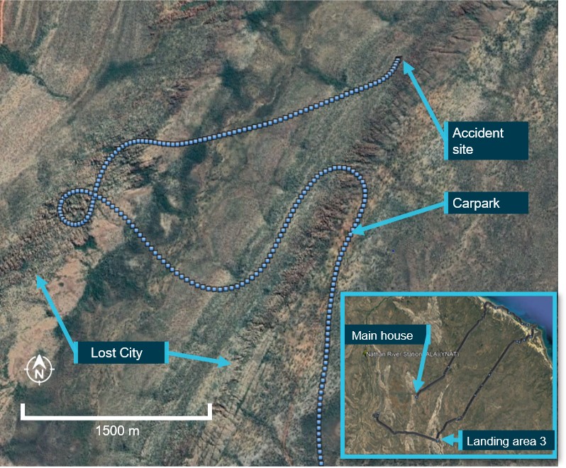
The helicopter departed at approximately 1533 local time and flew to a valley which had sandstone rock formations along both sides of the valley, known as the Lost City, rising approximately 150 ft above the valley floor. They initially flew along the eastern side and then returned on the western side of the valley, at approximately 500 ft above the valley floor (Figure 1).
Figure 1: VH-KOV flight track overflying the Lost City
The dotted line is the final track of VH‑KOV, the inset details the track the helicopter took for the sight-seeing tour.
Source: Google Earth and OzRunways data, annotated by ATSB
The pilot later recalled that, as the helicopter re-crossed the valley to return to the main house, they detected a burning smell and recalled that within a couple of seconds the engine began to run slightly rough.
In response to the malfunction, the pilot advised their initial concern was getting over the sandstone formations on the eastern side of the valley and then landing at a nearby carpark ‑ the only clear space to land in the area. As the pilot lowered the collective to reduce power, in case the engine failed, they checked the engine oil temperature, pressure and cylinder head temperature gauges, which were all in the normal range.
Within about 3 seconds, the vibrations through the helicopter increased. A passenger in the right rear seat later reported detecting a light in the top left of the console along with a warning buzzer at this time, however this was not recalled by anyone else in the helicopter. The pilot observed the engine RPM suddenly rise, then drop to zero and assessed that the engine had failed. Still on the valley side of the sandstone formations, the pilot initiated an autorotation into an area of less dense trees. Prior to the flare just above the treetops, the pilot instructed the passengers to ’brace’.
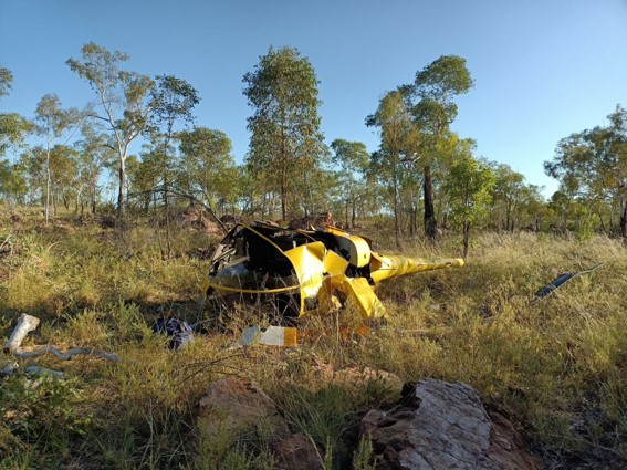
The pilot advised that the helicopter fell through the trees, contacting the ground initially on the right front side, nose low, and then the helicopter spun and rolled on to the left side facing the opposite way to the direction of travel (Figure 2).
Figure 2: VH-KOV
Source: Operator
The pilot advised that they undid their seatbelt and collected the emergency kit from under their seat. This contained a first aid kit, emergency rations and a satellite sleeve.[1] They then moved to the side of the helicopter and tried unsuccessfully to connect their mobile phone to the satellite sleeve (see the section titled Satellite sleeve) to raise an alert.
As a result of the impact, fuel was leaking from between the back seats onto the passenger in the rear left seat. The passenger located in the rear right seat, released themself from their seatbelt and assisted the other rear seat passenger out of the helicopter. The passengers asked the pilot for a fire extinguisher and were advised there was none onboard. They also requested a first aid kit, however this was not provided and the passengers later advised there was no first aid kit on the aircraft. Together, the passengers then assisted the front seat passenger to exit the helicopter.
The passengers then asked the pilot to ensure the emergency locator transmitter (ELT) (see the section titled Emergency locator transmitter) was working. The pilot re-entered the wreckage and selected the ELT remote switch in the cockpit to ON and reselected the main battery to ON, however the ELT unit failed to activate. As they were concerned about a fire starting due to the leaking fuel, the pilot and passengers began to walk to the carpark, about 1.5 km from their location.
When the helicopter did not arrive back at the main house at the pre-arranged SARTIME,[2] the operator took a second company R44 to search for VH-KOV. They flew directly to the landing area near the waterhole where the operator identified that the remains of the fire were still warm. Consequently, they flew towards the Lost City searching for VH-KOV as this was the next destination on the standard route flown during the scenic flight.
The operator detected the accident pilot and passengers near the carpark and landed the helicopter close to them. They then transported them, in 2 groups, back to the main house.
Two passengers sustained serious injuries, with the pilot and remaining passenger having minor injuries. The helicopter was substantially damaged.
Context
Helicopter
The Robinson Helicopter Company (RHC) R44 Raven I is a four-seat helicopter, with hydraulically boosted flight controls. It is powered by a Lycoming O-540-F1B5 series, six-cylinder carburetted piston engine. VH-KOV, serial number 1762, was manufactured in 2007 and placed on the Australian register in the same year. The front passenger and pilot doors had been removed, leaving the rear passenger doors installed. Quick disconnect pilot controls for the front left seat had also been removed. In July 2015, the helicopter had undergone an overhaul at 2,200 hours with a second overhaul due in 116.4 hours.
The helicopter was maintained in accordance with the manufacturer’s maintenance schedule, which required a periodic inspection every 100 hours or 12 months, whichever came first. A periodic inspection was completed on 30 July 2021 at 4,183.7 hours in-service. The accident occurred at 4,283.6 hours.
The RHC maintenance manual stated that the ‘inspection interval may be extended up to 10 hours, without accumulation’. There were a number of occasions where the operator had overflown the 100 hourly inspection requirements, however the following inspection interval had not been reduced by the overflown hours. The operator had recorded the overflown hours and had purchased a second R44 to reduce the likelihood of this occurring in the future.
Table 1 details maintenance actions conducted between the last periodic inspection and the accident.
Table 1: Overview of recent maintenance
Date
Hours
Description of maintenance conducted
16 May 2022
4,283.6
Accident
6 May 2022
4,261.1
Crank seal renewed, clutch actuator tension microswitch renewed, cooling fan balanced.
24 March 2022
4,235.4
New starter fitted
18 October 2021
4,234.6
50 hr - #2 cylinder replaced.
30 July 2021
4,183.7
Periodic – plus clutch actuator down and maximum limit microswitches renewed, crank seal renewed, upper and lower bearings serviced, #3 and 5 cylinders replaced, right magneto replaced.
Accident site
The ATSB did not attend the accident site. The helicopter was partly disassembled on site, including engine removal, and transported to Queensland for examination. Engine and airframe examinations were conducted between 19–21 September 2022.
Engine inspection
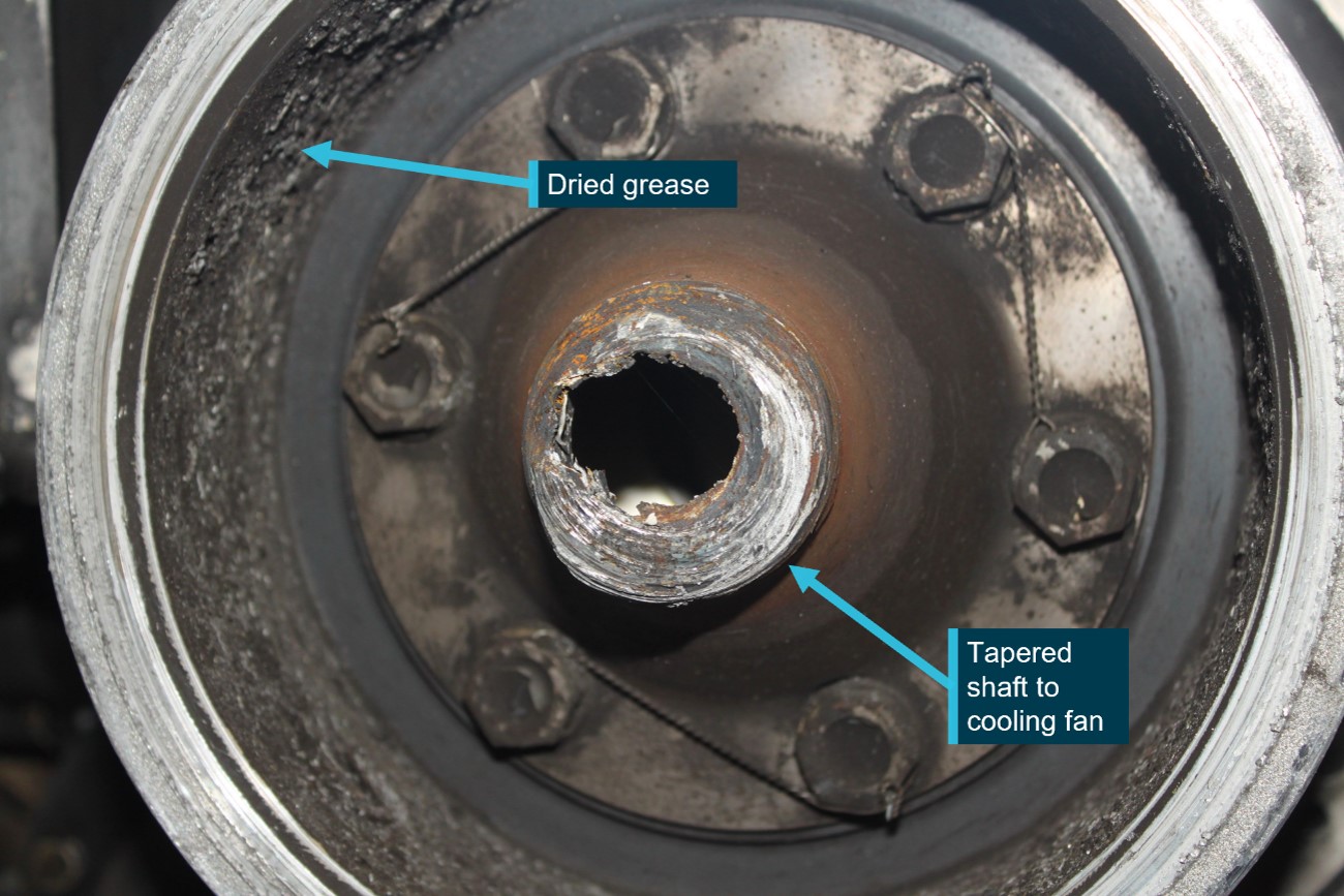
The engine teardown inspection was conducted at a CASA-authorised engine overhaul facility and observed by the ATSB. On removal of the cooling fan shroud, the engine cooling fan was found to have separated due to a fracture of the shaft at the clutch actuator lower bearing (Figure 3). The fracture location showed evidence of significant overheating. All associated components were retained for further detailed examination.
Some of the engine components displayed damage consistent with an overspeed event, however examination of the engine did not identify any condition or failure that would have resulted in sudden power loss or stoppage.
Helicopter examination
The ATSB examined the airframe at a storage facility. The tail cone and main rotor transmission assembly had been removed to assist transport. Similarly, the main rotor blades, sectioned near the hub, and some sections of the landing gear had also been removed and were not available for examination. The tail rotor gearbox and stabiliser assemblies separated from the helicopter during the impact sequence. All damage was consistent with overstress from impact forces. In addition, the examination identified:
flight control continuity
some impact damage to the fuel tanks however, the bladders were intact
the fuel tank interconnect line had fractured in overstress and was the reason for the post‑impact fuel leak
the main and tail rotor transmission assemblies exhibited no evidence of failure and could be rotated without restriction.
In summary, no failure or other condition, beyond the fan shaft failure, was identified that would have affected normal operation of the helicopter.
Lower sheave and fan shaft
Examination of the aft face of the lower sheave revealed accumulated grease consistent with it extruding past the lower bearing seal over a period of time. The maintainer reported wiping the sheave clean each time they worked on the helicopter however, the accumulated grease was not consistent with this having occurred at the last reported maintenance action requiring the bearings to be lubricated, 10 days prior to the accident or 22 hours of operation.
The fan shaft failed at the location of the lower bearing. The shaft exhibited deformation, necking, and gouging consistent with localised frictional heating. Circumferential scoring on the fracture surface was a result of the powered shaft contacting the bearing housing.
Figure 3: Lower sheave showing accumulated grease and failure of the shaft to the cooling fan
Source: ATSB
Lower bearing
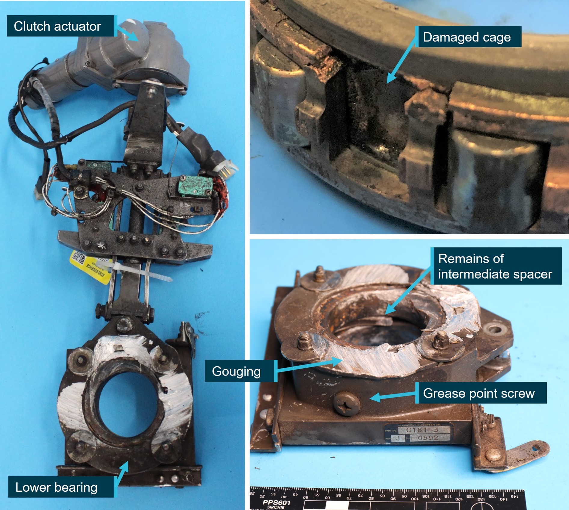
The ATSB examined the clutch actuator lower bearing at its Canberra technical facility. The forward face of the bearing housing exhibited matching gouging from contact with the rotating fractured engine output shaft (Figure 4). The cover plate was removed, and the bearing was found to have seized. The damage observed was consistent with intense heat and subsequent seizing of some of the rollers. The cage and intermediate spacer were also found to be heat-damaged.
Figure 4: Damage to lower actuator bearing
Source: ATSB
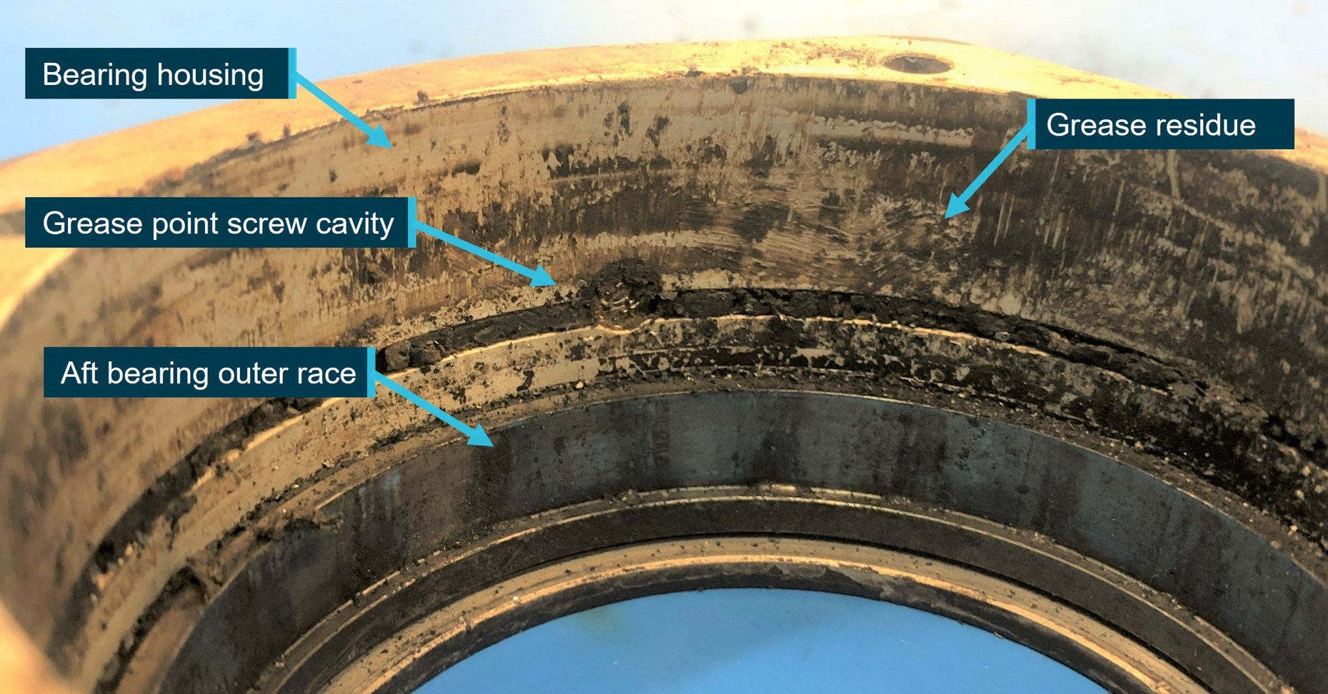
Grease residue was visible in the bearing housing (Figure 5) however, the intense heat associated with the bearing and fan shaft failure precluded the ability to determine the quality and quantity of grease and the condition of the seals prior to the occurrence.
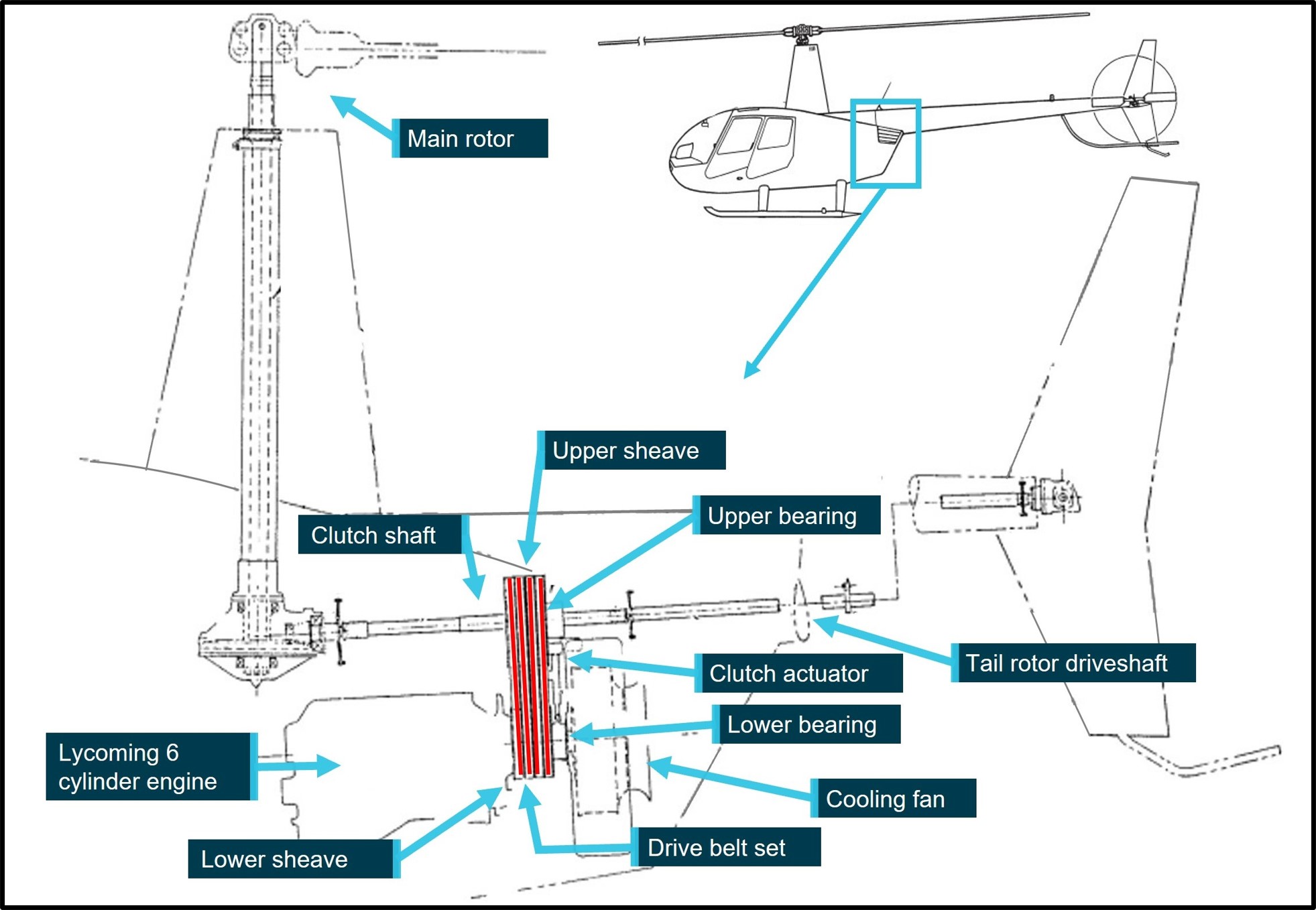
A V-belt sheave is bolted directly to the engine output shaft (Figure 6). Rubber V-belts transmit power to the upper sheave, which contains an overrunning clutch. The upper sheave transmits engine power via a shaft both forward to the main rotor and aft to the tail rotor.
A bearing, connected to an electric clutch actuator, is mounted between a direct-drive fan wheel and the engine on the engine output shaft. The fan supplies cooling air to the cylinders and oil cooler via a fibreglass and aluminium shroud.
Figure 6: R44 drive system
Source: Robinson Helicopter Company, annotate by ATSB
The electric clutch actuator (Figure 4) raises the upper sheave and tensions the V-belts. The actuator senses compressive load and switches off when the belts are properly tensioned. The ‘clutch’ caution light, located in the top left of the console, illuminates when the actuator is engaging, disengaging, or retentioning the V-belts. Regarding activation of the light, the pilot operating handbook (POH) stated:
If … the [clutch] light flickers or comes on in flight and does not go out within 10 seconds, pull CLUTCH circuit breaker and land as soon as practical. Reduce power and land immediately if there are other indications of drive system failure (be prepared to enter autorotation).
RHC Safety Tip 7 included:
A change in sound or vibration of the helicopter may indicate an impending failure of a critical component. If unusual sound or vibration begins in flight, make a safe landing and have aircraft thoroughly inspected before flight is resumed.
RHC Safety Notice SN-28
Listen for impending bearing failure included:
An impending ball or roller bearing failure is usually preceded by a noticeable increase in noise. The noise will typically start several hours before the bearing actually fails or before there is any increase in bearing temperature. To detect pending failure of a drive system bearing, the pilot should uncover one ear and listen to the sound of the drive system during start-up and shutdown. After the pilot becomes familiar with the normal sound of the drive system, he should be able to detect the noise of a failing bearing. The failing bearing will produce a loud whine, rumble, growl or siren sound…Failure of a bearing in flight could result in a serious accident.
Do not rely on telatemps to indicate impending bearing failure. A failing bearing may not run hot enough to black out the telatemps until it actually starts to disintegrate. This may occur only seconds before complete failure.
Clutch light warning
It is normal for the clutch light to come on occasionally in flight for a short time (approximately 3 to 6 seconds) to re-tension the drive belts. If the clutch light flickers or does not go out within 10 seconds, it can indicate a belt or bearing failure….
If additional symptoms of drive system failure (smell of hot rubber, noise or vibration) are present, land immediately. If tachometer needle split occurs, enter autorotation.
The operator advised they listened for sounds of bearing noises during the start-up and shutdown of the helicopter and had not detected any unusual noises or vibration. The accident pilot advised this was their first flight in VH-KOV this season and they had not noticed anything unusual during the flight.
Robinson Helicopter Company maintenance requirements
Periodic inspection
As part of a periodic inspection, a helicopter was subject to a ground inspection, engine run up and flight check. This included checking for ‘no unusual bearing noise when varying RPM through operating range (mechanic to listen near V-belt drive)’. These inspections were not included in the worksheet records however, the maintainer reported they were completed each time.
Lower bearing
The fan shaft assembly, including lower bearing had been replaced at the 2,200-hour overhaul. The periodic inspection checklist required:
Inspect as much of bearing as can be seen. Inspect fibreglass scroll area at bearing attachment brackets for signs of cracking. Check bearing seals for evidence of deterioration…Inspect bearing per Section 2.502 if discrepancies are found.
RHC required the bearing to be inspected as per section 2.502 whenever there was a bearing discrepancy, or the fan wheel was removed. Section 2.502 required removal of the fan wheel and disconnection of the clutch actuator from the lower bearing. The bearing was to be rotated by hand to ‘verify no roughness, scraping or excessive looseness’. In addition, there was a requirement to ‘verify no seal damage, no heat damage and lubricate as per Section 1.140’.
The lower bearing was to be lubricated as per Section 1.140 every 300 hours or 3 years, whichever came first, or as directed by 2.502. The procedure required 4–5 g of the specified grease to be injected, by syringe, into the bearing via a screw hole (Figure 4). A ground run was to be conducted at 102% RPM for 2 minutes. Following shutdown, the bearing was to be inspected and cleaned of escaped grease.
Upper bearing
There was no maintenance requirement to lubricate the upper bearing on the R44. In contrast, the upper bearing on the R22 was to be lubricated every 300 hours or 12 months. The R22 upper bearing lubrication procedure required a syringe be filled with 2–3 g of grease. The syringe tip was to be inserted against the ‘cleaned’ inner lip of the rubber seal and grease injected into the bearing. Once the syringe was removed, the deflected seal could be gently manoeuvred back into place.
VH-KOV bearing lubrication
A review of the maintenance records identified documented lubrication of both the upper and lower bearings (Table 2).
Table 2: Recorded lubrication of the upper and lower bearings
Date
Hours since previous service
Description of maintenance conducted
17 July 2015
New bearings installed
11 October 2016
367.8
Upper and lower bearing serviced
25 April 2018
515.6
Upper and lower bearing serviced
16 May 2019
401.7
Upper and lower bearing lube
26 August 20
374.1
The bearings were not specifically mentioned however, the 300-hour inspection included lubrication of the lower bearing
12 May 2021
221
Upper and lower bearing serviced
30 July 2021
103.5
Upper and lower bearing serviced
The maintainer advised they greased the bearings more often that the 300-hour requirement as the grease used, Grease 28, is very thin and as the helicopters were operating in a hot environment ‘we like to over maintain our bearings because if we didn’t, they would run dry’. Further, the maintainer advised they did not always certify the additional greasing in the maintenance records and therefore the frequency could not be verified.
Considering the recorded lubrication intervals of the lower bearing, Robinson Helicopters stated:
We do not see damaged lower bearings in any significant numbers. The ones that do get reported, typically have a poor service history. Every instance of bearing damage is going to be different so it would be impossible to apply a timeline to complete bearing failure after an unknown amount of damage. These particular bearings appear to have gone over 1000 hours since the most likely time of damage (after the 515-hour interval) and it is highly likely that signs of damaged bearings existed (noise, actuator issues, grease outside the seals, rough running bearings, etc.). There are two occasions…where the scroll had been removed for actuator repair when the mechanic should have put his/her hand on the bearing and rotated it to feel for roughness and any grease on the lower sheave would have been right there in plain view.
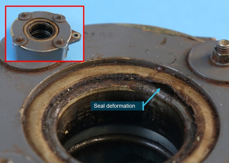
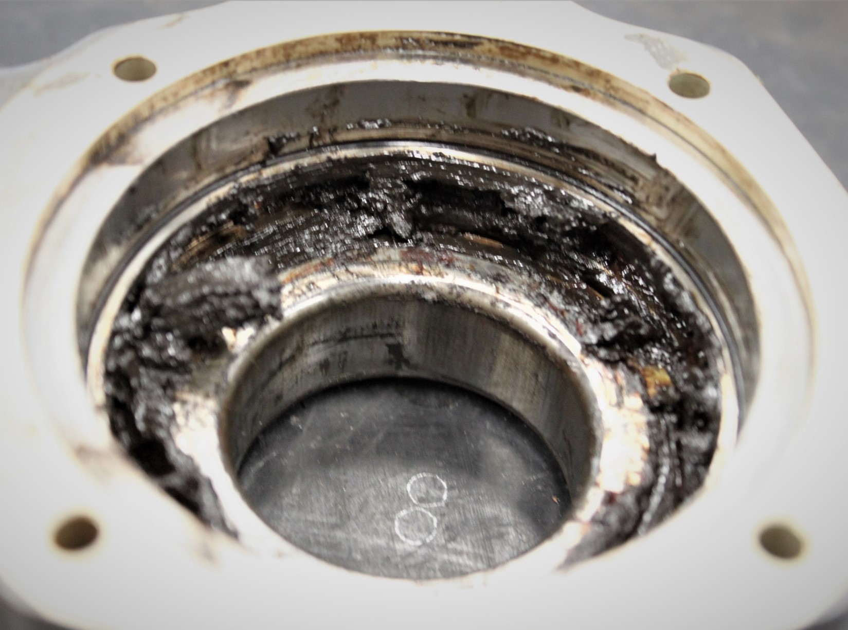
When questioned on the method for lubricating the upper bearing, the maintainer stated that they used the same method as for the lower bearing, via the screw hole. However, the ATSB inspected the upper bearing and noted the telatemp was covering the screw, with no evidence of it having been accessed. Additionally, the seal on the upper bearing, which was a type of rigid polymer, showed distortion consistent with the R22 syringe lubrication method (Figure 7). The grease was found to be solid and dark in colour (Figure 8). RHC advised that typically after 2,200 hours of operating, the grease will be dark brown but not grainy or gritty.
Figure 7: Distortion to the upper bearing seal
Source: ATSB
Figure 8: Grease found within the upper bearing
Source: ATSB
General provisions for lubricating bearings
Under-lubrication of a bearing can lead to over-heating due to the friction between the moving parts. However, lubricating more often than the procedures require can also result in over‑heating. When too much grease is added to the bearing cavity, it will result in the rotating bearing elements beginning to churn the grease and pushing it aside. This results in energy loss and rising temperatures. Over a long period of time, the grease will thicken into a hard, crusty build-up which can then impair lubrication and block new grease getting to the core. Excessive grease can also prevent heat from being dissipated, as the grease does not transfer heat from the load zone.
RHC advised the consequences of greasing more or less often than required was not specifically mentioned in the maintenance manual as it was considered to be a basic maintenance practice, which should be covered during initial training. RHC also advised that, lower bearing maintenance and troubleshooting was covered in their Robinson Helicopter factory maintenance course.
Troubleshooting
The maintainer had replaced 3 of the 4 microswitches for the clutch actuator at the last periodic inspection and 22 hours prior to the bearing failure (refer Table 1). Replacing the microswitches required that the fan wheel be removed and hence, as per the procedure, the bearing was required to be lubricated.
There was no information in the trouble shooting section of the RHC maintenance manual to advise that if the microswitches were being replaced, then the maintainer should inspect the bearing. However, RHC advised this information was covered in their Robinson Helicopter factory maintenance course.
The troubleshooting section for ‘clutch light flickers in flight’ included to check the upper and lower bearing for rough running however, the operator had not noted a flickering clutch light prior to the accident flight.
Emergency locator transmitter
The KANNAD 40 AF-Compact emergency locator transmitter (ELT) fitted to the helicopter consisted of a remote switch/annunciator, located in the cabin left of the cyclic, and a transmitter, located in the main transmission bay, and normally selected to ‘ARM’.[3] With the transmitter selected to ARM, the 3‑position remote switch/annunciator, with indicator light, operated as follows:
ON – ELT activated
ARM – permitted ELT activation when subjected to high ‘G’ load
Test/RESET – allowed brief functional testing of the ELT or reset in case of inadvertent activation
Light – red light illuminated when the ELT was transmitting.
The remote switch in the cabin was normally selected to ARM during flight.
During the helicopter inspection, the remote switch in the cockpit was found in the ON position. It was reported that the ELT unit was also found in the ARMED position after the helicopter was transported. There were no indications of damage to the battery. The ELT mount was found secured to the correct frame with the required Velcro mounting strap and additional secondary black cloth strap. The antenna was securely mounted under the cowl. Due to the discontinuity of the wiring after the helicopter was moved, the wiring was not examined.
The ELT did not activate when the accident occurred however, the signal was received by the Australian Maritime Safety Authority (AMSA) about 10 hours later. The ELT was not examined and therefore the reason for the delay in transmission could not be determined. AMSA was contacted and confirmed there were no areas in Australia where an ELT signal could not be detected by satellite. The accident was in a remote location and so interference by a person was considered unlikely. Despite this, interference by an animal or a change in the conditions were possible. There was no forecast rain in the area.
Robinson Helicopter Company ELT maintenance procedures
While optional on the R44, many were fitted with the Kannad automatic fixed 406AF ELTs. Due to the high frequency of fitment, the ELT was recorded as a periodic inspection item in Chapter 1 of the maintenance manual where it stated that United States (US)‑registered helicopters were required to be inspected every 12 months, in accordance with the Code of federal regulations (CFR) 91.207 Emergency locator transmitters. This regulation does not apply to helicopters, however RHC advised it was guidance for the inspection of an ELT for US‑registered helicopters.
The ELT was not recorded as an inspection item on the periodic inspection worksheets in Chapter 2 of the maintenance manual for the R44 helicopter. In contrast, the R22 and R66 helicopter periodic inspections did list the ELT in their periodic inspection worksheets however, the inspection was limited to ensuring the ELT was secure in its mount and would not foul the drivetrain.
Chapter 37 Electrical systems of the maintenance manual stated that the component manufacturer’s instructions should be followed to conduct maintenance.
ELT manufacturer maintenance procedures
The ELT manufacturer’s installation and operation procedures recommended that a self-test be conducted once a month and that it was mandatory that the batteries be changed:
on or before the battery expiration date
following 1 hour of real use
use in an emergency, or
inadvertent activation of unknown duration.
In addition, the manufacturer acknowledged that some national aviation authorities may require a periodic inspection. They provided service letter SL S18XX502-25-12 with guidance on periodic inspection procedures to satisfy requirements as directed by the US, Canada and Europe. The service letter also stated that all other countries should refer to the local regulations and it was ‘the responsibility of the customer (aircraft owner) to determine which tests are applicable to its ELT’.[4]
A periodic inspection of the ELT system should be carried out in accordance with approved data, which can include FAA AC 43 13-1B Chapter 12-22, if AC 43.13-1B is identified in the aircraft logbook statement as part of the aircraft maintenance data, or is otherwise identified or incorporated in an approved System of Maintenance.
The aircraft’s maintenance documentation stated that minor repair work should be conducted in line with AC 43.13-1B Acceptable methods, techniques, and practices – aircraft inspection and repair, however CASA confirmed that this does not include maintenance actions. CASA also advised Federal Aviation Regulations do not apply in Australia and therefore operators cannot maintain the ELT in accordance with FAR 91.207.
VH-KOV ELT maintenance history
The operator advised that they occasionally conducted a self-test on the ELT, which it always passed. They presumed the ELT was being maintained during the 100-hourly inspection conducted by the maintenance organisation.
The maintainer advised that they did not maintain ELTs as the helicopters they maintained either had the units removed or switched to OFF, as they would ‘randomly transmit’. They further advised that they would have informed the operator of VH-KOV that the ELT would not be maintained when they initially began to maintain the helicopter in 2016. The maintainer also stated that they endorsed the maintenance release to state that pilots are required to carry a personal emergency position-indicating radio beacon (EPIRB)[5] or satellite phone. The ATSB could find no record of this endorsement on the current or previous maintenance releases for VH-KOV.
The ATSB assessed the maintenance records and confirmed the ELT was serviced at the 2,200 hour major inspection on 17 July 2015. The only record of the ELT being inspected since then was on 2 occasions in 2018, when a different maintenance organisation conducted the periodic inspections. In addition, there was no note for the battery life in the maintenance records. An inspection of the ELT identified the battery had expired in March 2022.
At the time of the occurrence there was no regulatory requirement for VH-KOV to be fitted with an ELT (see the section titled Regulatory requirements around carriage of ELT). While optional, where it was fitted, it is important that a pilot is made aware of its operational status. Civil Aviation Advisory Publication (CAAP) 37-01 v5.1 Minimum equipment lists[6] included:
The operator or maintenance personnel must place the placard on or near inoperative equipment or instruments so that it is visible to the flight crew and alerts them to the inoperative equipment.
While the CAAP is only advisory, it represents best practice and an opportunity to ensure any pilot or maintainer is readily aware of the operational status of a component. There was no placard, or other notification, near the remote switch in VH-KOV to advise the ELT was not being maintained.
Inadvertent activation
AMSA was contacted to confirm if they had records of ELTs in Robinson Helicopters activating without cause. They advised that they were aware of the issue and considered it was due to:
the position of the ELT switch between the front passenger seat and the pilot seat allowing accidental activation of the ELT switch when entering or exiting the aircraft.
water ingress in the ELT assembly (the ELT is mounted inside the main transmission bay, which is not weatherproof). This was a regular and repeated event for Robinson helicopters.
RHC was contacted to see if they knew of any issues within the world fleet – they advised that one of their Australian repair stations confirmed they were aware of this issue. However, they advised there were no reports of issues in South Africa, Alaska or Canada other than ‘moving things in the cabin’ and hitting the switch.
The South African, US, and Canadian regulations require regular maintenance of the ELT unit.
The ELT manufacturer has advised that most inadvertent activations are due to water ingress in the wiring between the remote control panel and the ELT unit, however, this could not be verified.
Regulatory requirements around carriage of ELT
MOS Part 133 section 11.41 Carriage of ELTs required that a helicopter with more than 3 seats must be fitted with an automatic ELT. However, the transitional requirements allow operators to continue to operate under the previous legislation until 2 December 2023. The previous legislation, Civil Aviation Regulation 252A, permitted a helicopter on a flight within 50 NM from the departure aerodrome to operate without an ELT. As such, at the time, VH‑KOV did not require an ELT to be fitted.
The flight was conducted in a designated remote area and as such was required to carry ‘survival equipment for sustaining life appropriate for the area being overflown’. The pilot reported that the helicopter had a survival bag which contained a first aid kit, extra food, water, satellite sleeve, mosquito dome, thermal blanket, and a signal mirror. However, passengers disputed that a first aid kit was available.
Legislation
On 2 December 2021, new legislation came into force that required charter operations to comply with Civil Aviation Safety Regulations (CASR) Part 91, 119 and 133 and the corresponding manuals of standards. This introduced a number of changes to the requirements for this operation type, some of which were notified by the Civil Aviation Safety Authority (CASA) to operators in a document highlighting the key operational changes. During the introduction period, there were some transitional exemptions in place to give operators time to comply. Some of the changes, discussed below, were relevant to this occurrence.
At the time of the accident, the operator’s procedures had not been changed to reflect the new regulations however, they had submitted an exposition, written by a third-party contractor, to CASA for approval. They also advised that they had an expectation that the new requirements did not come into effect until March 2023.
Safety briefing
In accordance with the Manual of Standards (MOS) Part 133 Chapter 7 Safety briefings, instructions and demonstrations, the pilot of a helicopter must provide passengers with a verbal safety briefing. With the introduction of the new legislation, the information required to be briefed had been updated and now included, among other new requirements, information on when and how to assume the brace for impact (brace) position. The changes to the briefing requirements were not included in the key operational changes document promulgated by CASA. The legislation was in transition and after 1 December 2022, required an operator to supply a safety briefing card to all passengers specific to the helicopter type and model, which included detail on how to assume the emergency brace position.
The inclusion of having to show passengers how to brace during the oral safety briefing, in a helicopter with more than 3 passengers and less than 6 seats, was a new requirement and CASR 133.240(3)(b) required that this be specific to the aircraft type and model.
CASA released a multi-part advisory circular (AC) 91-19, AC 121-04, AC 133-10, AC 135-12 and 138-10 version 1.0 Passenger safety information, coincident with the requirement to brief passengers on the brace position coming into effect. This AC was to give operators ‘guidance regarding the requirements for safety briefing cards and passenger safety briefings, instructions and demonstrations’. It stated that when passengers are informed about the correct use of equipment and the actions to take in the event of an emergency, including how to brace, the survival rate was improved. It also stated that bracing before impact reduces:
flailing by having the forward-facing occupant flex, bend, or lean forward over their legs in some manner
secondary-impact injuries by pre-positioning the body, predominantly the head, against the surface that it would otherwise strike during that secondary impact, thus reducing the momentum of the head and other parts of the body.
The AC included an appendix that provided information on the recommended brace positions for specific seat positions and restraint types. However, it did not indicate how to brace in a helicopter with a 3‑point harness (lap strap and shoulder harness with a single diagonal strap), as was the harness available in the R44. General guidance, applicable to all brace positions, in section A.2.1 of the appendix advised that:
The lower torso should be firmly against the back of the seat.
The lap strap portion of the seatbelt should be worn as tight and as low across the hips as possible. The more tightly the lap strap is adjusted, the better restraint it will provide.
If the seatbelt includes a shoulder harness, the harness should be adjusted so that it is tight but does not pull the lap portion of the seatbelt upward.
The webbing of a lap strap and shoulder harness should lie flat against the body and should not be twisted.
Knees should be pressed together, and feet should be flat on the floor.
The US Code of federal Regulations Part 29 – Airworthiness standards: Transport category rotorcraft Subpart A 29.2 (a) required that a Category B rotorcraft[7] manufactured after 16 September 1992, was required to have a combined safety belt and shoulder harness with a single-point release. This requirement was also stated in section 27.785 (b) of the European Aviation Safety Agency CS-27 Certification specifications for small rotorcraft, which wasreleasedin 2003.
Advice was sought from CASA on how to brace in a helicopter with a 3-point harness, with the following response provided:
As detailed in A.3 of Appendix A to AC 133-10, there are a great number of variables affecting the brace position to be adopted. The AC aims to identify some general principles that will allow an operator to select an appropriate brace position in the context of their operation.
The information relating to brace positions contained in Appendix A of Multi-Part AC 133-10 is based on ICAO document 10086 Manual on Information and Instructions for Passenger Safety and Transport Canada Civil Aviation (TCCA) Advisory Circular TCCA AC 700-036 – Brace for Impact Positions for all Aircraft Occupants, which is also referenced in ICAO document 10086.
…Neither document (i.e., ICAO 10086 or TCCA AC 700-036) provide guidance on passenger brace positions for helicopters fitted with a 3-point harness.
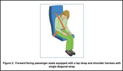
RHC was contacted to seek advice on how best to brace using the harness in the R44. They advised that they do not have specific information on the brace position and recommended to use either the brace position in section A.2.1 of the AC or the brace position A.5 Forward-facing passenger seats fitted with a lap strap and single diagonal shoulder harness, which stated:
A.5.1 In a forward-facing passenger seat fitted with a lap strap and single diagonal shoulder harness, passengers should brace according to Figure 2 [Figure 9] below and comply with the accompanying instructions:
a. Adjust shoulder harness to remove slack.
b. Rest chin on sternum, head should be tucked down as far as possible to try to eliminate secondary impact of the chin with the sternum.
c. Hands can be positioned on the lap, front edge of the seat can be held (do not lock elbows or wrists), or occupant can sit on palms of their hands (palms must be ‘up’ to avoid breaking wrists). Do not hold on to restraint system with hands; this can introduce slack into the restraint system.
Figure 9: Diagram of how to brace in a forward-facing passenger seat with 3-point harness
Source: CASA Multi-part advisory circular AC 133-10 Version 1.0
Transport Canada was also contacted in relation to the content contained within Canadian AC 700-036 and provided the following response:
Prior to the publication of AC 700-036, Transport Canada guidance had simply stated that ‘Helicopter occupant brace positions are the same as those for aeroplane occupants’, which was aligned with the guidance from the U.S. FAA at the time (i.e., AC 121-24C). During the development of the revised Canadian guidance in response to the recommendations contained in report DOT/FAA/AM-15/17, 2015-11-19 — Effect of Passenger Position on Crash Injury Risk in Transport-Category Aircraft, there was an identified need to provide guidance for helicopter occupants, specifically for those involved in offshore operations.
The focus was on offering guidance with respect to two specific configurations of passenger restraint systems: lap strap only and dual upper torso straps. As no new or unique recommendations were available or suggested for a helicopter passenger using a lap strap and diagonal shoulder strap (e.g., 3-point harness), the general guidance applicable to all aircraft passengers continues to be used for such a restraint system configuration (e.g., Sections 4.3 Forward-facing Seats Equipped with a Lap Strap and Shoulder Harness and 4.9 Aft-facing Seats Equipped with a Lap Strap and Shoulder Harness).
In the context of US operations, the Federal Aviation Administration (FAA) AC 121-24DAppendix 4 Brace-for-impact positions stated that:
Helicopter passengers … should adopt the same positions as recommended for aircraft seats of similar orientations and restraint system configuration; however, if possible, the occupants of all seat types should grip the edge of the seat pan, to help maintain orientation in the event of a rollover.
Both the pilot and the operator advised that they briefed passengers on how to brace in the event of an emergency. The operator advised they would advise passengers ‘not to lean forward’ and ‘always to sit up with a straight back’.
Safety brief prior to accident flight
On the morning of the accident flight, VH-KOV had been flown for 3–4 hours prior to arriving at Lorella Springs, as the operator’s second R44 had a minor fault. This resulted in the passengers waiting for the helicopter to arrive.
The passengers all reported they did not receive a safety briefing prior to the flight. However, they advised that they understood how to fasten the 3-point harness, their hand luggage was stored securely, and the operation of the headset was discussed with the pilot. When questioned sometime after the accident, the pilot advised they did not remember completing the briefing but would find it odd if they had not done so. They advised that normally their pre-flight briefing included:
avoiding the tail rotor
trip hazards such as skids
how to get in and out of the helicopter
door operation
seatbelt operation
no smoking
not to interfere with controls
brace position.
However, they also advised feeling slightly rushed due to the late arrival of the helicopter and that they were concentrating on checking the helicopter, refuelling, completing a fuel drain and checking the oil levels.
The passengers all commented that when the pilot called ‘brace’ prior to the accident, they did not know how to do so.
Pilot leaving controls
Prior to take-off, the passenger in the rear left seat could not close their door securely. In response, the pilot exited the helicopter, leaving the engine running and walked around to the left side to secure the door. The operator’s operations manual stated that:
the pilot-in-command must remain at the controls … from the time at which the engine is started prior to a flight, until the engine is stopped at the termination of a flight unless … the helicopter is fitted with a serviceable means of locking the cyclic and collective controls and … the pilot considers that their absence from the cockpit is essential to the safety of the helicopter...
The operator confirmed the helicopter had no modifications for locking the cyclic or collective.
The R44 is equipped with adjustable friction on the cyclic and collective, to allow a pilot to elect their desired level of force required to manipulate controls. This may be adjusted to suit conditions such as long flights, turbulence etc. These friction devices do not lock the controls and as such, RHC safety notice 17 stated:
NEVER EXIT THE HELICOPTER WITH THE ENGINE RUNNING
CASA had also advised in a previous ATSB investigation that a friction lock was not a substitute for a locking device.
CASR Part 91.550 (b) Seating for flight crew members required that at all times during the flight, ‘a pilot must occupy a pilot seat with the seatbelt securely fastened’. Where previously there was an exemption that a pilot of a helicopter could exit the cockpit if the helicopter had a means of locking the cyclic and collective, this exemption has been repealed.[8]
Operations manual
The operator’s operations manual, written by a third party, required that prior to boarding the helicopter the passengers be shown a helicopter safety card which provided information on how to enter and exit the helicopter when the rotors were turning. The passengers advised they did not receive a briefing on how to do this. One of the passengers reported that when they landed at the various stops, they were advised to leave the helicopter ‘going forward’. They exited the helicopter after landing while the rotors were turning at 2 landing sites carrying their fishing rods, and a third site, while the pilot allowed the helicopter engine to cool down.
Weight and balance
The operator’s operations manual stated that load calculations were to be made with actual weights for all passengers and baggage, using the loading form from the flight manual, however it then stated that a pre-calculated load and trim sheet could be used but may only be prepared by the chief pilot. The pilot advised they regularly use the pre-calculated weight form and an application on their electronic flight bag to calculate the weight and balance for the helicopter. The passengers advised they submitted their actual weights to the operator before the flight.
The ATSB assessed that the helicopter was operated within the weight and balance requirements for the flight.
Emergency equipment
Fire extinguisher
There was no fire extinguisher on the helicopter and the operator advised they did not carry one as they considered that if a fire started in flight, they would land immediately and exit the helicopter. However, their operations manual required that a portable fire extinguisher be carried on all flights.
Prior to December 2021, an airworthiness directive (AD/general/65 amendment 4) required that all aircraft with a maximum take-off weight of greater than 2,750 kg carry a fire extinguisher. The R44 does not fit into this category. CASA did recommend in AWB 26-002 Issue 3Selection and Installation of Handheld Portable Fire Extinguishers, that all aircraft have at least one fire extinguisher accessible to a pilot.
Manual of standards Part 133 section 11.46Hand-held fire extinguishers required that a rotorcraft must carry at least 1 hand-held fire extinguisher. However, the removal of the weight limit was not identified in the CASR Part 133 Key operational changes document. CASA advised this change was stated in the information they released to assist operators to write an exposition and had been discussed in early consultation with operators.
First aid kit
While it was reported that the helicopter had a survival bag which contained a first aid kit, the passengers advised that there was no first aid kit on the helicopter. The operator advised that when they found the pilot, they assessed that they were most likely in shock and injured and were concentrating on getting assistance rather than administering first aid. As the ATSB did not attend the accident site, the discrepancy in accounts regarding onboard emergency equipment could not be resolved.
Satellite sleeve
The operator advised that they used a satellite sleeve rather than a satellite phone in their operations. A satellite sleeve connected the user’s mobile phone to the satellite system and allowed them to make phone calls and send text messages. The operator advised that on the 20 April 2022, the unit was tested and found to be fully charged and operational. It was then switched to OFF and stored in a pouch on the helicopter.
The pilot had received training on how to use the unit and had the required application on their phone. Additionally, when the application is opened on a mobile phone, it provided simple instructions on how to use the device. The unit was tested after the accident and, while fully charged, it was not operational for unknown reasons.
Related occurrences
The ATSB identified two previous occurrences where the clutch actuator lower bearing had failed.
On the 25 November 1998, about 20 minutes after take-off, the pilot noticed a burning smell, and felt a slight shudder closely followed by the helicopter’s clutch light flickering. The pilot landed the float‑equipped helicopter on water with minimal impact forces.
The subsequent investigation revealed the fan shaft bearing located on the fan shaft between the engine and the cooling fan had overheated, melted and seized resulting in the shaft fracture. The examination by RHC revealed the lower actuator bearing lost lubrication after 926.4 hours of service, however they were unable to establish why this occurred with a distorted seal, loss of grease and water ingress considered the most likely sequence of events.
The second failure occurred in the US in 2016, where 2 people were seriously injured. The helicopter was over a saltwater pond, about 300 ft above ground level. At that time, the pilot felt a lateral shudder followed by the clutch light illuminating. The helicopter then began a violent yaw and the low oil pressure light illuminated. The pilot performed an autorotation to shallow water near the shoreline.
Examination of the airframe revealed that the engine cooling fan had separated with the lower sheave being caked in grease, consistent with grease leaking from the clutch actuator lower bearing for a significant time. The roller bearings were found seized with no grease recovered. The investigation found that the times in the aircraft maintenance documentation had been incorrectly recorded. Consequently, the helicopter had not been maintained in accordance with procedures and the airframe major overhaul was due 59.5 hours prior to the accident. The lower bearing would have been replaced during this overhaul. Also, the lower bearing had not been serviced in accordance with procedures. While the bearing had been lubricated annually in the 2 years preceding the accident, there was no recorded servicing during a period of 4 years 11 months and 685.1 hours prior to this.
Safety analysis
Introduction
While flying at about 500 ft above a valley floor, the helicopter started to vibrate and within seconds, the clutch actuator lower bearing failed. This resulted in a loss of drive to the main and tail rotors and it is possible the engine stalled as it was unloaded. As the helicopter was flying over rising terrain, the pilot had very few recovery options, and they conducted an autorotation into trees resulting in serious injuries to 2 passengers and minor injuries to the remaining passenger and the pilot. The helicopter sustained substantial damage.
This analysis will consider the factors around the seizure of the lower bearing, passenger briefing, the introduction of new legislation by the Civil Aviation Safety Authority, and the issues around the maintenance of emergency locator transmitters (ELTs) in Australia.
Lower bearing seizure
The investigation identified that the lower bearing seized, resulting in the failure of the fan shaft. The maintainer advised that they had checked the bearing for roughness during maintenance about 20 flight hours prior to the accident and did not detect any issues. Additionally, the operator advised they regularly listened for unusual noises in the drive train as they shut down the engine, and none had been detected. On the day of the occurrence, the helicopter had been operated for approximately 5.1 hours, including several engine shut-downs, with neither pilot identifying anything unusual prior to the sudden failure of the bearing.
After the occurrence lower bearing was installed at the major inspection, the time between lubrication was initially greater than the required 300 hours. However, in more recent times, the maintainer advised they were lubricating the bearing more frequently than required as they felt this was warranted in the hot operating environment. In addition, the lower bearing was to be lubricated every time the fan wheel was removed, which had the potential to result in more frequent lubrication. However, the fan removal also afforded the opportunity for thorough inspection of the lower sheave.
Robinson Helicopter’s assessment was that bearing damage that ultimately led to failure most likely occurred during the period of initial under‑lubrication following fitment. They further advised that signs of bearing damage, including:
noise
rough running bearings
actuator issues
grease outside the seals
should have been evident. As detailed above, no noise or roughness was identified, but the accumulation of dried grease on the lower sheave indicated that grease had been leaking past the seal and/or over greased for an extended period. The bearing was also reaching the end of its service life.
Distortion to the upper bearing seal was consistent with that bearing being lubricated despite there being no procedural requirement to do so. Further, inspection identified that the grease was solid and therefore not likely to have been effectively lubricating and cooling the bearing.
Due to the extent of the damage to the lower bearing, the specific reason for its failure could not be identified. However, the available evidence indicates it was probably due to the inconsistent lubrication of the bearing. Both lubricating the bearing more and less often than required by the procedures can result in damage. Not following the maintenance procedures increases the likelihood of the bearings failing prior to their service life. Further, such failures can occur at a critical phase of flight, where the opportunity for a successful forced landing may be reduced.
The RHC maintenance procedures did not specify that the lower bearing should not be over lubricated and included a requirement to lubricate the bearing every time the cooling fan was removed, which was required when the clutch micro switches were replaced. The procedures also did not identify, in the trouble shooting section, that frequent changing of the micro switches could be an indication that the lower bearing was failing.
Passenger briefing
The passengers did not receive a safety briefing prior to the flight, which resulted in them being unaware of the safety equipment in the helicopter. Having knowledge of what is available, and how it is used, is important in the event of an emergency, especially if the pilot is incapacitated and/or the flight is in a designated remote area. Fortunately, this did not affect the outcome on this occasion as the operator responded quickly when the helicopter did not return after the SARTIME had elapsed.
Although not related to the accident, the passengers also did not receive a specific briefing on how to leave the helicopter with the rotors turning. Landing in a remote area, with no ground staff and unknown/undulating terrain levels, increases the risk of passengers inadvertently walking into the rotor arcs. They were also carrying fishing rods, which added to the risk level. According to the United States (US) Federal Aviation Authority (FAA) Helicopter flying handbook, ‘People have been injured, some fatally, in helicopter accidents that would not have occurred had they been informed of the proper method of boarding or deplaning’.
Another result of not receiving a safety brief was that the passengers were not given any information on how to brace during the accident. While all 3 passengers advised they did not know how to brace, it is difficult to assess if their injuries were increased as a result of not being briefed. An accident of this nature, where the helicopter falls through trees and spins, introduces many forces which cannot be foreseen when designing a general brace position. It is also very difficult to assess which people will adopt the demonstrated brace position when faced with an emergency.
Regulatory change management
Despite the variables outlined above, research has shown that knowledge of the appropriate brace position offers the best chance to reduce injury. As such, it is now a requirement that during the passenger safety briefing prior to a flight, passengers are informed of the brace position specific to the aircraft type. Despite that, this requirement, along with other new requirements for the passenger safety brief, for operators of smaller helicopters, were not identified in the document released by CASA to advise operators what had changed with the introduction of new regulations.
Also, the multi-part Advisory Circular (AC), released by CASA to give operators guidance for safety briefing cards and passenger briefings, did not give specific advice on how to brace in a helicopter with a 3-point harness. This harness type is used extensively in helicopters flying in Australia, including the R44.
The helicopter did not have a fire extinguisher on board, contrary to the operator’s operations manual. If, as on this occasion, operators are using a third party to write their exposition, it is vital that they have a full understanding of what is written to ensure they are complying with their own company procedures.
A fire extinguisher is now mandatory in all helicopters operating under the Civil Aviation Safety Regulation (CASR) Part 133. The change to this requirement for helicopters weighing less than 2,750 kg was also not stated in the document released to advise operators around the changes to the regulations.
As these were relatively small wording changes as part of the introduction of extensively revised regulations, they could be overlooked by an operator.
ELT maintenance procedures
The ELT fitted to VH‑KOV did not activate until many hours after the ground impact. The maintainer had not maintained the unit since taking over the aircraft maintenance and had not advised the operator of this. However, as the unit eventually operated, it was likely serviceable.
The Robinson Helicopter Company (RHC) maintenance manual Chapter 1-General stated that US registered helicopters should be maintained in accordance with FAR 91.207. This regulation, however, applied to airplanes only. The statement was also unclear as to how helicopters based outside the US were to be maintained. In addition, Chapter 2 - Inspections did not list a procedure for an inspection of the ELT, although inspections were listed for both the R22 and R66 helicopters. These inspections listed requirements to ensure the ELT unit was secure in the helicopter rather than ensuring it was operational.
The maintenance requirements from the ELT manufacturer required that the battery be changed when required and recommended that a self-test be conducted monthly. If the ELT had been placarded as not being maintained, this may have prompted the operator to have performed a self-test of the unit on a regular basis. As the self-test was a recommended procedure, it is not required to be written in any maintenance documentation. As such, it is likely an operator/pilot could be unaware of the procedure. An investigation conducted by the ATSB –AO-2021-020 Wirestrike and collision with terrain involving Robinson R22, VH-KLY 75 km west-north-west of Hay, New South Wales on 26 May 2021– is an example of where the pilot had selected the ELT remote switch in the cockpit to ARM, however, the ELT was selected OFF at the unit. If the pilot of VH‑KLY had conducted a self-test of the unit, they would have realised that the unit was not operational.
The CASA Airworthiness Bulletin (AWB) 02-002, released on 15 November 2013, recommended that maintainers conduct maintenance on the ELT in accordance with approved data. However, as is the case for this helicopter, the approved data only required the operation of the unit to be checked when the batteries were replaced. This could result in the unit’s operational status only being ascertained every 6-7 years.
As shown in the ATSB research report, A review of the effectiveness of emergency locator transmitters in aviation accidents, ELTs in Australia only activate in 40-60% of accidents, but are effective in saving lives. Additionally, and as confirmed by AMSA, ELT units in Robinson Helicopters also activate erroneously. The lack of a formalised maintenance requirement may contribute to this.
Findings
ATSB investigation report findings focus on safety factors (that is, events and conditions that increase risk). Safety factors include ‘contributing factors’ and ‘other factors that increased risk’ (that is, factors that did not meet the definition of a contributing factor for this occurrence but were still considered important to include in the report for the purpose of increasing awareness and enhancing safety). In addition ‘other findings’ may be included to provide important information about topics other than safety factors.
These findings should not be read as apportioning blame or liability to any particular organisation or individual.
From the evidence available, the following findings are made with respect to the to the clutch actuator lower bearing seizure and collision with terrain involving Robinson Helicopter R44, VH-KOV on 16 May 2022.
Contributing factors
During cruise flight, the clutch actuator lower bearing seized resulting in a total loss of drive from the engine to the rotor system. The subsequent autorotation and collision with terrain over an inhospitable area, resulted in serious injuries to 2 passengers and minor injuries to the pilot and remaining passenger.
The clutch actuator lower bearing was not being maintained in accordance with the manufacturer’s maintenance procedures, which likely resulted in the bearing failure.
Other factors that increased risk
The passengers did not receive a pre-flight safety brief resulting in them being unaware of the emergency procedures, safety equipment and brace position. They also exited the helicopter prior to the accident while the rotors were turning, without a specific briefing.
There was no fire extinguisher on board the helicopter. While this did not influence the outcome in this case due to the absence of post‑impact fire, it reduced the overall safety of the flight.
As part of the regulatory changes to Civil Aviation Safety Regulation Part 133, the Civil Aviation Safety Authority changed the regulations relating to the carriage of fire extinguishers and passenger briefing. These safety‑related changes were not promulgated to operators in documentation related to the regulatory changes.
Civil Aviation Safety Regulation Part 133 required that pilots brief passengers on the emergency brace position with information specific to their aircraft type and model. However, while the Civil Aviation Safety Authority provided guidance on how to brace in some configurations, they did not provide specific information on how to brace in a helicopter, like the R44, which had a 3-point harness.
The emergency locator transmitter did not activate until 10 hours after the accident, reducing the likelihood that the helicopter’s occupants would be found in a timely manner.
The emergency locator transmitter was not being maintained and the maintainer had not advised the operator.
The Robinson R44 maintenance manual did not give clear guidance on how an emergency locator transmitter (ELT) should be maintained in aircraft outside the United States (US) and there was no procedure for inspecting its security. The US regulations referred to aeroplanes only and so there is no regulatory requirements to maintain an ELT in the US.
The Civil Aviation Safety Authority did not provide clear guidance on how emergency locator transmitter units should be maintained.
The emergency locator transmitter (ELT) manufacturer Kannad’s maintenance procedures stated that the monthly self-test of the ELT unit was recommended rather than required, which could result in the unit’s operation only being ascertained every 6-7 years. Current regulations do not mandate such a test.
Safety actions
Whether or not the ATSB identifies safety issues in the course of an investigation, relevant organisations may proactively initiate safety action in order to reduce their safety risk.
All of the directly involved parties are invited to provide submissions to this draft report. As part of that process, each organisation is asked to communicate what safety actions, if any, they have carried out or are planning to carry out.
Safety action by the involved maintainer
The maintainer of the helicopter involved contacted each of the operators of the helicopters they maintained to ensure they were aware that the emergency locator transmitter (ELT) was not being maintained and to ensure they were carrying a personal locator beacon in the helicopter.
Safety action by the Civil Aviation Safety Authority addressing the guidance on how to brace in a helicopter with a 3-point harness
The Civil Aviation Safety Authority has released multi-part advisory circular (AC) 91-19, AC 121-04, AC 133-10, AC 135-12 and 138-10 version 1.1 Passenger safety informationto include information on how to brace in a helicopter with a 3-point harness.
Safety action by the Civil Aviation Safety Authority addressing the guidance on emergency locator transmitter (ELT) installation and maintenance
The Civil Aviation Safety Authority has updated airworthiness bulletin (AWB) 02-002 to include information on ELT maintenance and guidance if the information contained within the aircraft’s maintenance schedule is not sufficient.
Safety action taken by Orolia the manufacturer of the emergency locator transmitter (ELT)
The manufacturer of the ELT has advised that the discrepancy between the service letter and the installation manual will be corrected to reflect that the self-test should be a recommended practice as the current regulations do not require a self-test.
Glossary
AMSA Australian Maritime Safety Authority
AWB Airworthiness bulletin
AC Advisory Circular
AD Airworthiness Directive
CAAP Civil Aviation Advisory Publication
CASA Civil Aviation Safety Authority
CASR Civil Aviation Safety Regulations
CAR Civil Aviation Regulations
ELT Emergency locator transmitter
FAA Federal Aviation Authority
MOS Manual of Standards
POH Pilot operating handbook
RHC Robinson Helicopter Company
SL Service letter
US United States
Sources and submissions
Sources of information
The sources of information during the investigation included the:
pilot of the accident flight
passengers
operator
maintainer
Australian Maritime Safety Authority
Civil Aviation Safety Authority
Robinson Helicopter Company
photographs taken on the day of the accident
Transport Canada.
References
ATSB research report, A review of the effectiveness of emergency locator transmitters in aviation accidents, May 2013, Australia
Airworthiness Bulletin 02-002 Emergency Locator Transmitter (ELT) installation and maintenance, November 2013, Australia
CASA (Civil Aviation Safety Authority) multi-part Advisory Circular (AC) 91-19, AC 121-04, AC 133-10, AC 135- 12 and 138-10 version 1.0 Passenger safety information, August 2021, Australia
Transport Canada Advisory Circular (AC) 700-036 Brace for impact positions for all aircraft occupants, Issue 1, September 2016 Canada
FAA (Federal Aviation Authority) Advisory Circular 121-24D Appendix 4 Brace-for-impact positions, May 2019 United States
Under section 26 of the Transport Safety Investigation Act 2003, the ATSB may provide a draft report, on a confidential basis, to any person whom the ATSB considers appropriate. That section allows a person receiving a draft report to make submissions to the ATSB about the draft report.
A draft of this report was provided to the following directly involved parties:
pilot of the accident flight
operator
maintainer
Australian Maritime Safety Authority
Civil Aviation Safety Authority
United States National Transportation Safety Board
Robinson Helicopter Company
Transport Canada.
Bureau d'Enquêtes et d'Analyses (France)
Orolia SAS
Submissions were received from:
pilot of the accident flight
operator
maintainer
Civil Aviation Safety Authority
Robinson Helicopter Company
Bureau d'Enquêtes et d'Analyses (France)
Orolia SAS
Transport Canada
passengers
The submissions were reviewed and, where considered appropriate, the text of the report was amended accordingly.
Appendices
Appendix A – Draft investigation report submission from the helicopter maintainer
The helicopter maintainer’s representative requested that their submission be attached to the report. As such, the following document is appended:
Introduction
We note that the ASTB has prepared a draft report in relation to a clutch actuator lower bearing seizure and collision with terrain involving Robinson Helicopter Company, R44, VH-KOV near Nathan River Station, Northern Territory on 16 May 2022. The following is a submission pursuant to section 26 of the Transport Safety Investigation Act 2003 on behalf of the “maintainer” referred to in that report.
We note that s.25(3) of the Act includes that, “A published report may include submissions that were made by persons to the ATSB in response to a draft report... “. We further note that s.12AA(1)(c)(i) of the Act provides that the ATSB's function is to improve transport safety by means that include identifying factors that contribute, or have contributed, to transport safety matters. This submission is intended to assist the ATSB in identifying factors that may have contributed to this incident.
The draft report
The Executive Summary for the draft report includes that, “The ATSB found that during cruise, the clutch actuator lower bearing seized resulting in a total loss of drive from the engine to the rotor system. This bearing had not been maintained in accordance with the maintenance procedures, which likely resulted in its failure.” We submit that theory is drawn from certain assumptions, which assumptions may need revision in light of certain objective facts. We further submit that the objective facts suggest another factor may have contributed to the incident.
Page 5 of the draft report states that, “Examination of the aft face of the lower sheave revealed accumulated grease consistent with it extruding past the lower bearing seal over a period of time. The maintainer reported wiping the sheave clean each time they worked on the helicopter however, the accumulated grease was not consistent with this having occurred in the last 10 days or 22 hours of operation. The fan shaft failed at the location of the lower bearing. The shaft exhibited deformation, necking, and gouging consistent with localised frictional heating. Circumferential scoring on the fracture surface was a result of the powered shaft contacting the bearing housing.”
At page 22 of the draft report it is then stated that, “The accumulation of dried grease on the lower sheave indicated that grease had been leaking past the seal and/or over greased for an extended period.” The opinion that the dried grease was an accumulation of residue from a prolonged period of over-lubrication is, with respect, incorrect.
Firstly, to the use of the term “over-lubrication” is a mischaracterisation of the increased maintenance conducted by the maintainer. While additional events of lubrication occurred, they did not involve an application of excess lubricant so as to cause extrusion of that excess such as would cause a residue to accumulate. The process by which the maintenance is conducted and the components themselves limit the volume of lubricant that may be applied and do not result in residual lubricant remaining present.
Secondly, the as noted at page 4 of the draft report indicates, the components examined by the ATSB were apparently inspected approximately 126 days after the incident: “The ATSB did not attend the accident site. The helicopter was partly disassembled on site, including engine removal, and transported to Queensland for examination. Engine and airframe examinations were conducted between 19–21 September 2022.” That period between the incident and examination, during which the components in question were left undisturbed, does not appear to be accounted for in the draft report observations about the extent to which a “minimal dried grease” was observed on the lower actuator bearing housing (page 8, Figure 5).
Thirdly, the draft report does not account for the possibility that a “minimal” amount of lubricant may have escaped into the housing after the failure, at which point the components would have been super-heated due to the friction generated in the incident, which heat may have then caused the lubricant to dry out between the incident and the inspection 126 days later.
Fourthly, while the Executive Summary of the draft report states that, “During cruise flight, vibrations were detected through the helicopter, subsequently the pilot observed the engine RPM rise and then drop to zero”, the body of the report provides relevant additional details:
i. At page 1, the draft report notes that, “The pilot reported that, as the helicopter re-crossed the valley to return to the main house, they detected a burning smell and recalled that within a couple of seconds the engine began to run roughly.”
ii. At page 2, the draft report then notes that, “As the pilot lowered the collective to reduce power, in case the engine failed, they checked the engine oil temperature, pressure and cylinder head temperature gauges, which were all in the normal range. Within about 3 seconds, the vibrations through the helicopter increased. The pilot observed the engine RPM suddenly rise, then drop to zero and assessed that the engine had failed.”
iii. At page 9 the draft report notes that, “The operator advised they listened for sounds of bearing noises during the start-up and shutdown of the helicopter and had not detected any unusual noises or vibration.”
The theory that dried grease accumulated over time from over-lubrication and caused the bearing to fail appears to be borne out of the opinion that what is depicted in Figure 5 is an accumulation of dried grease from over-lubrication. Without that opinion, another source for failure must be considered.
The observations of those onboard do not require a conclusion that the causative event initiated from over-lubrication. Another possibility is that the lower fan shaft failed first, leading to a disruption of the bearing, ultimately leading to seizure, which seizure then expelled a quantity of lubricant which was super-heated and subsequently dried before being examined. This possibility is consistent with the observations of those onboard.
The clutch actuator lower bearing engages the main rotor. Seizure means an automatic loss of drive. Another possibility is that the bearing, which was nearing the end of its serviceable term, spontaneously failed and caused the seizure. Seizure as a result of spontaneous failure could, given the damage observed, have resulted in the expulsion of the lubricant that was subsequently observed in Figure 5 as “minimal dried grease”.
At page 5 of the draft report it is said that, “The maintainer reported wiping the sheave clean each time they worked on the helicopter however, the accumulated grease was not consistent with this having occurred in the last 10 days or 22 hours of operation.” Thus the observation of “minimal dried grease” is offered as a reason for rejecting the maintainer’s evidence. However, since the maintainer’s evidence is otherwise uncontradicted and unchallenged, the “minimal dried grease” may be seen as consistent with having in fact resulted from the seizure, rather than being the cause of it.
Further evidence that the incident may have originated with the lower fan shaft (and note due a residue of dried grease which the maintainer says was not present prior to the incident) comes from the condition of the clutch actuator observed in Figure 4 on page 7 of the draft report. Close examination of Figure 4 reveals that the clutch actuator is in an over-travel state with the tension spring damaged. It is also apparent that the fan shaft has failed from the lower bearing inner race spinning and creating excess heat, which heat would then have transferred to the lower bearing, which by failure would have super-heated the lubricant upon seizure would have expelled it to where it was then observed 126 days later.
We submit that what can also been seen in the photo of the lower bearing inner race is abrasions that may have been caused from excessive clearance between the fan shaft and lower bearing inner race. If the failure originated in connection with the fan shaft, what appears as scoring on the fan shaft may be linked to weakening and shearing. We note that the lower bearing, fan shaft and fan dropping down into the fan scroll would have released drive belt tension, causing an engine over speed and loss of drive to the main rotor transmission. This is consistent with the observations of those onboard, reported at pages 1 and 2 of the draft report:
“The pilot reported that, as the helicopter re-crossed the valley to return to the main house, they detected a burning smell and recalled that within a couple of seconds the engine began to run roughly”; and
“As the pilot lowered the collective to reduce power, in case the engine failed, they checked the engine oil temperature, pressure and cylinder head temperature gauges, which were all in the normal range. Within about 3 seconds, the vibrations through the helicopter increased. The pilot observed the engine RPM suddenly rise, then drop to zero and assessed that the engine had failed.”
We submit that these alternatives – the incident arising from a failure of either the fan shaft or the bearing should be included in the final report. We further submit that the characterisation of the maintainer’s increased frequency of lubrication as “over-lubrication” is not correct.
The specifications for a 12-month, 100 hourly check in section 2.140 of the manual, under item 7, states that if any discrepancies exist the maintainer is to inspect the bearing in accordance with section 2.502. That section then directs to section 1.140, which instructs the maintainer to lubricate the bearing with 4-5 grams of grease. Similarly, in section 2.501, it states that if any discrepancy is suspected, or the fan is removed, to proceed in accordance with section 2.502 and section 1.140, which is to lubricate the bearing with 4-5 grams of grease. In addition, in table 1 scheduled maintenance inspections it is stated that the maintainer is to grease the bearings in accordance with section 1.140, i.e. with 4-5 grams of grease every 300 hours or 3 years. Each of these grease applications is for the same amount – 4-5 grams. That is the prescribed volume on each occasion. The application of that amount, in accordance with the manual is, by definition, not over-lubrication.
In addition, because the bearing is a greaseable bearing and not a non-greaseable sealed bearing, Section 1.140 bearing lubrication instructs the maintainer to ground run the machine at 102% for 2 minutes after lubrication, and to then shut down and wipe any escaped excess grease. By following this procedure on each occasion the maintainer has not over-lubricated and has prevented any accumulation of residue.
Conclusion
Maintenance in accordance with the manual includes re-lubrication of the bearing every time the fan comes off. Given the various occasions for removal of the fan, the manual indicates re-lubrication of bearing could be, for example, as frequent as every 100 hours or whenever additional work is carried out that requires removal of the fan. The procedure for re-lubrication ensures that “over-lubrication” does not result. The hypothesis that the bearing seized due to “over-lubrication” by the maintainer therefore is, with respect, not correct.
We submit that the ATSB should consider instead the two alternative hypotheses: that the bearing near the end of its serviceable life spontaneously failed, or the incident independently arose due to some unspecified failure in the fan shaft. We also request that this submission should be included with the final report in accordance with s.25(3) of the Act.
Purpose of safety investigations
The objective of a safety investigation is to enhance transport safety. This is done through:
identifying safety issues and facilitating safety action to address those issues
providing information about occurrences and their associated safety factors to facilitate learning within the transport industry.
It is not a function of the ATSB to apportion blame or provide a means for determining liability. At the same time, an investigation report must include factual material of sufficient weight to support the analysis and findings. At all times the ATSB endeavours to balance the use of material that could imply adverse comment with the need to properly explain what happened, and why, in a fair and unbiased manner. The ATSB does not investigate for the purpose of taking administrative, regulatory or criminal action.
Terminology
An explanation of terminology used in ATSB investigation reports is available here. This includes terms such as occurrence, contributing factor, other factor that increased risk, and safety issue.
Publishing information
Released in accordance with section 25 of the Transport Safety Investigation Act 2003
Ownership of intellectual property rights in this publication
Unless otherwise noted, copyright (and any other intellectual property rights, if any) in this report publication is owned by the Commonwealth of Australia.
Creative Commons licence
With the exception of the Coat of Arms, ATSB logo, and photos and graphics in which a third party holds copyright, this publication is licensed under a Creative Commons Attribution 3.0 Australia licence.
Creative Commons Attribution 3.0 Australia Licence is a standard form licence agreement that allows you to copy, distribute, transmit and adapt this publication provided that you attribute the work.
The ATSB’s preference is that you attribute this publication (and any material sourced from it) using the following wording: Source: Australian Transport Safety Bureau
Copyright in material obtained from other agencies, private individuals or organisations, belongs to those agencies, individuals or organisations. Where you wish to use their material, you will need to contact them directly.
[1] A device used to connect mobile phones to the satellite system.
[2] A SARTIME is the time nominated by a pilot for the initiation of Search and Rescue (SAR) action.
[3] Selecting the ELT transmitter to OFF is only recommended for maintenance, storage and shipment. The ELT can also be activated by selecting the transmitter to ON
[4] The service letter, in contradiction to the installation procedures, stated that the monthly self-test was a requirement, however the manufacturer advised this is not the case.
[5] Emergency position-indicating radio beacon: A type of emergency locator beacon used to locate people in need of immediate assistance.
[6] The minimum equipment list (MEL) is a list which provides for the operation of aircraft, subject to specified conditions, with particular equipment inoperative. It is prepared by an operator in conformity with, or more restrictive than, the manufacturer’s MEL established for the aircraft type.
[7] Rotorcraft with 1) a maximum weight of 20,000 pounds or less and 2) 9 or less passenger seats may be type certificated as Category B rotorcraft.
[8] CAO 95.7 – exemption from the provisions of the Civil Aviation Regulations 1998 – Helicopters (12/12/2004) was repealed on 2 December 2021.
[9] The helicopter maintainer disagreed with the contributing safety factors identified by the ATSB and requested that their submission be included in the final investigation report in accordance with s.25(3) of the Transport Safety Investigation Act 2003 (Appendix A).
On 16 January 2022, an instructor and student pilot were conducting circuit training at Devonport Airport, Tasmania, in a Jabiru J120-C aircraft, registered 23-1531 and operated by Freedom Flight Pty Ltd.
While on the downwind leg, the student in the left seat saw a white flash and called ‘seagull’, believing they saw a bird. At the same time, the instructor felt a jarring and observed that the propeller had separated from the aircraft. The instructor immediately took control of the aircraft, closed the throttle and conducted an unpowered landing onto the runway. There were no reported injuries or damage to the aircraft.
What the ATSB found
In-flight separation of the propeller occurred as a result of fracture of the propeller bolts. Notwithstanding the reported bird strike, the propeller bolts showed extensive fatigue crack propagation. The extent of cracking was such that the propeller could also have separated without an external influence, or would have separated with continued operation.
The propeller washers were not installed in accordance with the maintenance manual, which may have contributed to accelerated wear and subsequent cracking of the bolts.
Safety message
It is important to conduct maintenance and thorough inspections of hardware in accordance with the manufacturer’s requirements and recommendations, as deviations can have unintended, and potentially hazardous consequences. Particular attention should be paid to evidence of abnormal contact or movement between components as indications of loose or fretting components.
The investigation
Decisions regarding whether to conduct an investigation, and the scope of an investigation, are based on many factors, including the level of safety benefit likely to be obtained from an investigation. For this occurrence, a limited-scope investigation was conducted in order to produce a short investigation report and allow for greater industry awareness of findings that affect safety and potential learning opportunities.
The occurrence
On 16 January 2022, an instructor and student pilot were conducting circuit training at Devonport Airport, Tasmania, in the Jabiru J120-C aircraft, registered 23-1531 and operated by Freedom Flight. The weather was fine and the aircraft was operating as normal.
While on the downwind leg, the student in the left seat saw a white flash and called ‘seagull’, believing it was a bird. At the same time, the instructor felt a jarring and observed that the propeller had separated from the aircraft. The engine revolutions immediately increased as the engine was unloaded, however there was no other unusual noise, vibration or indications associated with the propeller separation.
The instructor immediately took control of the aircraft, closed the throttle and conducted an unpowered landing onto the runway. There were no reported injuries or damage to the airframe. The propeller assembly (Figure 1) was subsequently located in two pieces on the beach adjacent to the airport.
The Jabiru J120-C was a 2-seat, light sport aircraft with a high-wing and fixed undercarriage. It was powered by a Jabiru 2200B 4-cylinder engine, driving a Jabiru C000242 series, 2-blade, fixed-pitch propeller, constructed of laminated hoop pine, sheathed in fibreglass. The occurrence propeller, serial number 3416, was manufactured in April 2013.
Propeller assembly
The Jabiru C000242-series wooden propeller was attached to the propeller flange by 6 propeller bolts (Figure 2). The bolts were specified as either AN4-37A or AN4-40A.[1] They were installed with the bolt heads facing rearwards, through stainless steel guide bushes inserted into the flange. The bushes were a close fit (no free-play) in the rear of the propeller hub.
A woven fibreglass composite backing plate and aligning plate was positioned either side of the propeller hub and provided for attachment of the spinner. The aligning plate effectively provided a sealed cavity (minus the bolt holes) in the front of the spinner.
Source: Jabiru technical manual JTM001-9 except detail as indicated (annotated by ATSB)
The bolts were assembled with Belleville washers,[2] which was a recommended alternate propeller mounting system introduced by Jabiru in 2005. Wood shrinks or expands as a result of changes in its moisture content, which in turn is related to changes in humidity in the environment in which it is stored and used. Belleville washers deflect during assembly with the application of bolt/nut torque. That deflection allows for the assembly to better account for seasonal changes in the wooden hub dimensions and as such, reduce the frequency of inspections required to check and maintain correct propeller bolt tension. Jabiru Service Bulletin JSB014-1 indicated that a loss of bolt tension can cause the propeller to move and fret[3] on the mounting flange.
Component examination
The propeller assembly, forward of the propeller flange was found intact, with the exception of the fracture and separation of approximately 35 cm of the tip of one blade (Figure 1). The separated blade tip was located a short distance away from the main assembly. The propeller had been disassembled prior to receipt by the ATSB.
The six propeller bolts had fractured under the head. The bolts and two types of washers were contained by the spinner and aligning plate along with a covering of sand (Figure 3). Three of the bolts had retained washers and the rest of the washers were loose in the spinner. There were a total of 36 (dull, grey) Belleville washers recovered out of the 48 required by the Jabiru Propeller Technical Manual JPM3L1-4. There were also 17 (bright) flat washers, with a smaller diameter than the Belleville washers. The reason for the odd number of flat washers was not established. It was possible that one was misplaced during the disassembly. The 18 flat washers would have allowed for six Belleville and three flat washers per bolt, as seen on one of the bolts in Figure 3.
The inset of Figure 3 shows an absence of gaps between some pairs of Belleville washers, indicating that some of the washers were stacked in parallel (nested), rather than in series (facing in opposite directions) as required by JPM3L1-4 and illustrated in Figure 2. Altering the washer stack in terms of the number or orientation of Belleville washers will change the total deflection available (combined height under the individual discs) and/or the spring rate.[4]
The bolt fracture surfaces showed marks consistent with high-cycle fatigue crack progression (Figure 4). Some of bolts had fretting wear adjacent to the fatigue crack origin, as well as helical wear part way along the bolt shank. The wear was coincident with the narrowest section of the bore in the guide bush. The bolt material was consistent with the AN4 specification and there was no observed corrosion or other gross defects.
Figure 3: Propeller bolts and washers as recovered
The nylock nuts[5] were all present, in good condition with approximately the same amount of engagement with the threads. The nuts were very close to bottoming out on the bolt threads. Each nut had between one-half to three-quarters of a turn before reaching the end on the thread runout.
There was no evidence of a propeller blade defect at the fractured tip. There was also no observed organic matter or smearing to indicate a bird strike. A chord segment of the propeller hub, between two boltholes, had fractured. Discolouration of the timber on the flange side, adjacent to the guide bushes indicated a small amount of pre-existing cracking, however the bulk of the fracture was recent. Similar pre-existing cracking through the boltholes was also evident on the intact portion of the hub. The guide bush holes were damaged during the failure sequence and unable to be fully examined, however two holes that were able to be test fitted were snug with a bush inserted to the appropriate depth. The drive side of the propeller and spinner backing plate were blackened and worn, indicating relative movement between the two surfaces.
A set of exemplar washers were purchased for comparison to those from the occurrence (Figure 5). The occurrence washers were visibly (edge quality and coating) and dimensionally different. They were also a different alloy to the exemplars, however both conformed to the dimension and material requirements of the supplier specifications.[6]
Washer stack deflection was compared between occurrence washers oriented in series and arranged as-recovered, per Figure 3. The stack height was measured with vernier callipers in the
Figure 5: Comparison between a stack of occurrence (left) and exemplar (right) washers in series.
Source: ATSB
unloaded condition (nut finger-tight) and then the nut was torqued to 72 inch-pounds (the required installation torque) and remeasured. The washers in series deflected approximately 1 mm before becoming effectively flat. When arranged as recovered, with a number of the washers in parallel, the stack compressed approximately 0.5 mm (Figure 6).
In order to estimate the effectiveness of the washer deflection in service, monthly weather statistics were obtained from the Bureau of Meteorology to determine the average relative humidity changes in the north of Tasmania. Propeller hub shrinkage or expansion was then calculated for 0.1% radial dimensional change for hoop pine per 1% moisture content change, and a 1% change in equilibrium wood moisture content for every 5% change in relative humidity. Based on this, the as-received washer stack was theoretically able account for the changes in average relative humidity and the corresponding propeller hub dimensional changes due to wood moisture content, although it was close to the estimated maximum.
Figure 6: Deflection test using washers from the occurrence propeller, arranged as recovered
Minor scale in 0.5 mm for illustrative purposes.
Source: ATSB
Instructor comments
The instructor commented that the jarring felt at the time of the propeller separation and the fracture of the blade was consistent with what they had experienced previously in a wooden propeller-driven aircraft as a result of a bird strike during take-off.
Propeller maintenance
Jabiru propeller technical manual JPM3L1-4 contained maintenance information for C000242‑series propellers. The manual indicated that the propeller bolts must be checked after the first flight following installation[7] and then every 100 hours and/or annually thereafter. Guidance for the 100-hourly inspection included:
Remove the spinner and carry out a thorough visual inspection checking for cracking, fraying, corrosion and other damage.
Check for loose, missing, corroded or damaged fasteners and hardware.
Check for deposits and radial markings which indicate fretting between moving parts.
Visually check the condition of the propeller, looking for damage to the leading-edge protection, glass de-lamination and cracks, splits or crushing of the propeller timber.
Check the tension of the propeller bolts/nuts – Tension if required.
Check spinner and Prop Tracking.
In addition to the above, the annual inspection also recommended removal of the propeller from the aircraft, to enable a more thorough inspection for cracking, wear and damage, a test fit of the propeller drive bushes and a check of the propeller balance.
The operator advised that the propeller had been with the aircraft since purchase and was maintained in accordance with the maintenance manual. The maintenance logs indicated that the aircraft and therefore the propeller assembly, had approximately 1,100 hours in service since new. There was no record of the attachment hardware being changed.
There were no recent aircraft maintenance log entries that included specific notes on the propeller. The most recent engine and airframe 100-hourly inspection was recorded 2 months (56 hours) prior to the occurrence, with nil defects noted. This inspection was endorsed by the operator, who previously held the required[8] Level 2 maintenance authority, but which had expired in 2016. During interview, the operator noted the importance of the Belleville washers and installation torque and indicated that they hadn’t had to re-tension the bolts during inspections since the washers were introduced.
The operator also advised that the propeller had most recently been removed 6 months (around 150 hours) prior to the occurrence, and that the wear on the propeller was within limits at that time. The propeller removal was not recorded in the logs and the operator was unable to recall who had removed, inspected and reinstalled the propeller.
Previous occurrences
Review of the ATSB aviation occurrence database over the past 10 years, found five other instances of Jabiru in-flight propeller separation from the mounting flange.
The only other occurrence investigated by the ATSB occurred in December 2021 (AO-2022-004). In that instance, the propeller separated from a J170-C approximately 8 hours after installation, after the pilot experienced a transient period of unusual engine vibration. The propeller bolts had fractured and there was evidence of movement/fretting on the propeller flange, however the propeller assembly was unable to be located and therefore an assessment of the propeller hardware was not able to be conducted.
The wear on the bolt shank adjacent to cracking, the spinner backing plate and the propeller mounting plate indicated relative movement between the assembly components, which would typically result from low clamping force / bolt tension, or a lack of security in the assembly. In the absence of material defect in the components or hardware, the possible reasons for this included loose-fitting guide bushes, misassembly and/or loosening of the assembly during operation.
The fracture of the propeller hub and damage to the propeller guide bush holes precluded a thorough test for guide bush fitment. While it remained a possibility, the fit of those that could be tested suggested that loose bushes was unlikely. Similarly, it was not possible to assess whether the observed low bolt tension had been influenced by low nut torques at installation.
The deviation of the washer stack from Jabiru’s assembly instructions had the potential to affect the security of the assembly. This was primarily due to the reduction in the environmental dimensional change (shrinkage) in the wooden propeller hub that could be accommodated before a loss of bolt tension resulted. In this instance, the complete washer stack as recovered was, although marginal, theoretically able to cope with the estimated changes (shrinkage and expansion) from propeller moisture content. However, the partial stacks recovered were inconsistent, which left the possibility that one or more of the washer stacks had a smaller deflection than that tested. With a reduced tolerance for dimensional changes, the risk of movement and fretting of the components increased.
The operator reported that the propeller was maintained in accordance with the maintenance manual. As such, there were inspections pertaining to the installation hardware at the most recent 100-hourly inspection. The propeller was not required to be fully disassembled and removed during that inspection, however the difference in size and colour between the flat and Belleville washers should have been identifiable during the checks for loose, missing, damaged or corroded hardware, or checking of bolt tension. The reason that the operator did not detect the assembly error was not known, but it was a missed opportunity to not only identify the error, but to further examine the affected components for unusual wear.
While it is unclear if there was any influence on this occurrence, the operator had continued to exercise the privileges of an expired maintenance authority. In doing so, it removed any regulatory oversight checks with respect to the operator’s maintenance currency and recency. In general, while this is not necessarily directly reflective of an individual’s maintenance competency, it did prevent opportunities for assuring ongoing suitability to correctly maintain an aircraft to the expected standard.
Findings
ATSB investigation report findings focus on safety factors (that is, events and conditions that increase risk). Safety factors include ‘contributing factors’ and ‘other factors that increased risk’ (that is, factors that did not meet the definition of a contributing factor for this occurrence but were still considered important to include in the report for the purpose of increasing awareness and enhancing safety). In addition ‘other findings’ may be included to provide important information about topics other than safety factors.
These findings should not be read as apportioning blame or liability to any particular organisation or individual.
From the evidence available, the following findings are made with respect to the In-flight propeller loss involving Jabiru J120-C, registration 23-1531 at Devonport Airport, Tasmania on 16 January 2022.
The propeller washers were not installed in accordance with the maintenance manual, which reduced the ability of the assembly to tolerate environmental dimensional changes.
The operator had exercised privileges of an expired maintenance authority.
Sources and submissions
Sources of information
The sources of information during the investigation included:
Freedom Flight Pty Ltd
The student pilot
Jabiru Aircraft Pty Ltd
Recreational Aviation Australia
References
Simpson WT, 1998, Equilibrium Moisture Content of Wood in Outdoor Locations in the United States and Worldwide. U.S. Department of Agriculture, Forest Service, Forest Products Laboratory research note.
Department of Agriculture, Fisheries and Forestry, Queensland, 2013, Hoop Pine – Araucaria (plantations), factsheet.
Submissions
Under section 26 of the Transport Safety Investigation Act 2003, the ATSB may provide a draft report, on a confidential basis, to any person whom the ATSB considers appropriate. That section allows a person receiving a draft report to make submissions to the ATSB about the draft report.
A draft of this report was provided to the following directly involved parties:
Freedom Flight Pty Ltd
The student pilot
Jabiru Aircraft Pty Ltd
Recreational Aviation Australia
There were no submissions received.
Purpose of safety investigations
The objective of a safety investigation is to enhance transport safety. This is done through:
identifying safety issues and facilitating safety action to address those issues
providing information about occurrences and their associated safety factors to facilitate learning within the transport industry.
It is not a function of the ATSB to apportion blame or provide a means for determining liability. At the same time, an investigation report must include factual material of sufficient weight to support the analysis and findings. At all times the ATSB endeavours to balance the use of material that could imply adverse comment with the need to properly explain what happened, and why, in a fair and unbiased manner. The ATSB does not investigate for the purpose of taking administrative, regulatory or criminal action.
Terminology
An explanation of terminology used in ATSB investigation reports is available here. This includes terms such as occurrence, contributing factor, other factor that increased risk, and safety issue.
Publishing information
Released in accordance with section 25 of the Transport Safety Investigation Act 2003
Ownership of intellectual property rights in this publication
Unless otherwise noted, copyright (and any other intellectual property rights, if any) in this report publication is owned by the Commonwealth of Australia.
Creative Commons licence
With the exception of the Coat of Arms, ATSB logo, and photos and graphics in which a third party holds copyright, this publication is licensed under a Creative Commons Attribution 3.0 Australia licence.
Creative Commons Attribution 3.0 Australia Licence is a standard form licence agreement that allows you to copy, distribute, transmit and adapt this publication provided that you attribute the work.
The ATSB’s preference is that you attribute this publication (and any material sourced from it) using the following wording: Source: Australian Transport Safety Bureau
Copyright in material obtained from other agencies, private individuals or organisations, belongs to those agencies, individuals or organisations. Where you wish to use their material, you will need to contact them directly.
[1] ‘Army-Navy’ US military specification bolts. The first number refers to the bolt diameter in 1/16 of an inch. The dash number denotes the bolt grip length in relation to a size chart. The bolts were typically made from one of a number of grades of high strength steel (minimum 125,000 psi tensile strength) and were cadmium plated.
[3] Fretting refers to wear involving small amplitude relative movement or vibration between contact surfaces.
[4] The load required to compress a spring by a unit distance.
[5] Nuts with a self-locking feature, consisting of an internal, reduced-size nylon or polymer ring designed to increase the torque required to move the nut on a bolt and make it more resistant to loosening in service.
[6] Dimensions to Deutsches Institut für Normung DIN 6796-6, and spring steel to DIN 17221 or 17222. The height of the occurrence washers was the minimum allowable after a permanent set test per DIN 267 part 26.
[7] This requirement was originally in reference to CASA Airworthiness Directive AD/PFP/1, which was cancelled in 2016. Jabiru updated the manual to version JPM3L1-5 in August 2022. Which removed the reference to the AD, but retained the inspection requirements.
[8] To perform maintenance on RAAus-registered aircraft used for flight training.
On 22 December 2021, at around midday, a student pilot departed Muchea/Greenside ALA, Western Australia, on a training area solo flight in the Jabiru J170-C aircraft registered 24-7496. On return, during the downwind leg of the circuit, the pilot commenced configuring the aircraft for landing, at which point a vibration from the engine was felt. The engine gauges read as normal and the vibration reduced with throttle reduction.
Shortly after, while on final approach, the pilot observed emus crossing the runway around the normal touchdown point and conducted a go-around. While on climb at around 800 feet, there was a loud ‘bang’ and the pilot observed that the propeller had separated from the aircraft. The pilot subsequently landed in a paddock, approximately 2.5 km from the end of the runway. The aircraft suffered minor damage and the pilot was uninjured. The propeller was not recovered.
What the ATSB found
The propeller separated as a result of fracture of the propeller bolts that was likely related to a loss of bolt tension. However, the factors contributing to any loss of tension were not able to be determined.
The student pilot had recently undertaken several hours’ worth of flight emergency training, which positively influenced the pilot’s actions and contributed to the safe outcome.
Safety message
Pilots should remain vigilant to transient or persistent changes to the normal operation of their aircraft. Such changes may be indicative of an impending failure of a critical component or system. As such, a prudent course of action would be to land as soon as practicable and have the aircraft inspected. Even so, in-flight emergencies will continue to occur, and when faced with such an event, emergency training practice and recurrence will increase the likelihood of pilots achieving a safe outcome.
Decisions regarding whether to conduct an investigation, and the scope of an investigation, are based on many factors, including the level of safety benefit likely to be obtained from an investigation. For this occurrence, a limited-scope investigation was conducted in order to produce a short investigation report, and allow for greater industry awareness of findings that affect safety and potential learning opportunities.
The occurrence
On 22 December 2021, at around midday, a student pilot departed Muchea/Greenside aeroplane landing area (ALA), Western Australia, on a training area solo flight in the Jabiru J170-C aircraft registered 24-7496. The pilot flew for approximately 70 minutes before returning to land at Greenside ALA. During this time, the pilot did not observe anything unusual with the aircraft’s performance.
The pilot joined the downwind leg of the circuit (heading west) and around this time, observed a burning pine smell, which was significant enough for the pilot to look around the cabin and outside for a source. The smell dissipated and was not observed for the remainder of the flight. Shortly after observing the smell, the pilot commenced configuring the aircraft for landing, at which point a significant vibration from the engine was felt. The pilot immediately checked the engine gauges and noted everything was normal. The vibration lessened significantly upon reduction of the throttle. As a result, the pilot re-checked the gauges, which were still normal, and focused on continuing the circuit.
While on final approach, the pilot observed emus crossing the runway around the normal touchdown point, which prompted the pilot to conduct a go-around. The pilot then flew down the remainder of the runway, cleared the hangars and then the highway at the eastern end of the airstrip, climbing through approximately 500-600 feet. No abnormal vibration was observed at any point during the go-around.
Between 5 and 10 seconds after clearing the highway, at an altitude of around 800 feet, there was a loud ‘bang’ which was heard by witnesses back at the hangars. At the same time, the pilot noted that the propeller had separated from the aircraft.
After securing the engine, the pilot elected to land ahead and configured the aircraft for a glide to reach some cleared paddocks. The pilot then made a MAYDAY[1] call that was received nearby at Pearce RAAF base, who contacted the chief flying instructor at Muchea. The pilot subsequently conducted an uneventful landing in a paddock, approximately 2.5 km from the end of the runway. The aircraft suffered minor damage to the nose cowl (Figure 1) and right, main landing gear. The pilot was uninjured.
The student pilot had approximately 70 hours flying experience, all of which was on the Jabiru J170. The pilot had recently undertaken an area training flight with an instructor and had 3 hours of emergency procedures training, including engine failure, over the previous 5 weeks. The pilot commented that the training positively influenced their actions, helped them remain calm and contributed to the safe outcome.
The pilot also had a debrief with the operator after the event and made the following comments to the ATSB:
They had not experienced anything like the vibration previously. Despite this, everything appeared to be safe to fly the aircraft in the short term because the vibration had reduced rapidly with throttle reduction and the engine gauges read as normal. Nevertheless, after landing, the pilot had planned to discuss with the chief pilot what was experienced.
In hindsight, recognising the vibration as an indicator of impending failure, there was an opportunity to cut the circuit short and land as soon as possible. Alternatively, there was an opportunity to land long, past the emus. However, the pilot was also concerned about the possibility of more emus further down the runway, which had been encountered previously.
Aircraft information
The Jabiru J170-C is a 2-seat, light sport aircraft with a high-wing and fixed undercarriage. The subject aircraft was manufactured and first registered in 2010. It was powered by a Jabiru 2200B 4-cylinder engine, with a Jabiru C000242-series, 2-blade, fixed-pitch propeller, constructed of hoop pine, sheathed in fibreglass.
The occurrence propeller, serial number 3050, was manufactured in January 2009. The operator estimated that it had 1,500-1,600 hours in service. The propeller was overhauled by the manufacturer in February 2021. The leading-edge urethane wear strip started to disbond after about 50 hours post-overhaul and was returned to the manufacturer for repair. After the repair, the operator visually inspected the propeller, checked the balance, and re-fitted it to the aircraft. The propeller subsequently accumulated 7.9 hours up to the occurrence.
Operator information
The operator held RAAus Level 2 maintenance authority and had owned and maintained Jabiru aircraft since 2009. The operator advised that
Propellers are fitted and inspected in accordance with the Jabiru maintenance manual, including a check of the propeller bolt torques after the first flight following fitment.
Prior to the occurrence flight, the chief pilot conducted a thorough pre-flight inspection, as a demonstration to a new student pilot. The propeller was inspected for damage and security, including a check for any play or movement of the propeller on the end of the crankshaft. There were no anomalies noted.
There were no reported unusual engine or propeller vibrations in the flights since the most recent propeller fitment.
The propeller attachment hardware was periodically replaced when displaying any significant wear.
Physical evidence examination
Propeller assembly and maintenance
The Jabiru C000242-series wooden propeller was attached to the propeller flange by 6 propeller bolts (Figure 2). The propeller bolts were specified as either AN4-37 or AN4-40, meaning they were approximately 4 inches (10 cm) in length. They were installed with the bolt heads facing rearwards. The gap between the rear of the flange and the front of the engine cowl did not allow for the bolts to be installed or removed with the cowl in place.
The bolts were installed through stainless steel guide bushes, inserted into the flange. The bushes are a close fit (no free-play) in the rear of the propeller hub. A woven fibreglass composite backing plate sits between the flange and propeller hub and provides for attachment of the spinner.
In this installation, the bolts were assembled with Belleville washers,[2] which was a recommended alternate propeller mounting system, introduced by Jabiru in 2005. The purpose was to allow the assembly to better account for seasonal changes in the wooden hub dimensions and as such, reduce the frequency of inspections of propeller bolt tension. Jabiru maintenance manual JPM3L1-4 indicated that the propeller bolts must be checked after the first flight following installation and then recommended every 100 hours and/or annually thereafter. Jabiru Service Bulletin JSB014-1 indicated that a loss of bolt tension can cause the propeller to move and fret[3] on the mounting flange.
In an effort to locate the separated propeller, the operator conducted an extensive aerial photographic survey (approximately 89 hectares), covering the flightpath and surrounding area to the east of the airstrip. Despite this, the separated propeller assembly was not recovered. As a result, component examination by the ATSB was limited to the propeller flange and 5 (of 6) remaining guide bushes (Figure 3).
The flange forward face exhibited abrasive wear patterning consistent with the fibreglass weave of the backing plate, on one-half of the forward face of the flange. The wear had removed the surface contamination from the flange and microscopic grooves were worn into the surface in some areas. The presentation of the wear indicated that it likely predated the first indications of vibration observed by the pilot.
Localised fretting wear was present between the guide bush and the rear face of the flange (Figure 4). The greatest amount of wear was associated with those bushes on the opposite half of the flange from the wear on the forward face. Surface contamination from the flange had also transferred to the bushes. This was most notable on those holes with the most wear indications.
One of the bushes had a section of the wall fractured laterally and the remaining bushes had small amount of deformation on the inside rim of the forward face. This was a result of contact with the bolt shank at the point of the propeller separation.
There were no indications of how the missing bush separated from the flange, however wear around the associated hole indicated that it was in situ in the time leading up to the occurrence.
Figure 4: Wear from drive bush on propeller flange
Source: ATSB
Previous occurrences
Review of the ATSB aviation occurrence database found five other instances of in-flight propeller separation, involving Jabiru aircraft:
The ATSB investigated a March 2013 occurrence (AO-2013-046), involving a propeller separation as a result of fatigue fracture of the bolts securing the propeller flange to the engine crankshaft, and therefore a different point of fracture to the subject occurrence. In response to that occurrence and safety issues identified, Jabiru took several safety actions to reduce the likelihood of reoccurrence.
Another 2013 event, a wooden propeller separated from a J200B aircraft while in the cruise phase of flight. Four of the bolts had fractured at the heads and two remained in situ, having torn through the hub. It was a reported as probable maintenance issue, related to over‑tensioning the propeller bolts.
In 2021, the flight crew of a J230 aircraft experienced noticeable, but not severe vibration that did not respond to a reduction in throttle. The engine operation was normal. The pilots continued the flight and because of the continued vibration, they assessed alternative landing options. Approximately 20 minutes after the vibration onset, the propeller departed the aircraft. The pilots subsequently identified a suitable landing area and conducted a forced landing on a track through a paddock.
Also in 2021, the pilot of a J160 aircraft reported a very rough running engine and after 30 seconds, the engine stopped. The pilot conducted a forced landing into a clearing and, upon exiting the aircraft, observed that the propeller had separated from the aircraft and that the propeller mounting bolts had fractured.
In January 2022, a propeller separated as a result of broken propeller bolts after a reported bird-strike. That incident is the subject of ATSB investigation AO-2022-013.
No injuries were sustained in any of the above occurrences.
Safety analysis
Propeller separation
The operator indicated that the propeller bolts were installed in the correct orientation, and as such, there was insufficient clearance between the propeller flange and nose cowl for the bolts to back out of the flange. Therefore, the absence of propeller bolts retained in the flange indicted that the propeller ultimately separated from the aircraft due to fracture of the bolts.
Without the bolts available for examination, the reason for the propeller bolt fractures was not conclusively determined. However, the evidence of movement and fretting on the flange was consistent with a loss of clamping force or low bolt tension. The pilot-observed vibration and smell of burnt pine in the minutes prior to the separation was also evidence of relative movement between the wooden propeller and the mounting hardware. Vibration in a normally rigid system will introduce abnormal loading conditions, subjecting components to stresses beyond design considerations. Additionally, fretting wear can significantly reduce the fatigue limit and hence, the working life of components in the assembly.
The ATSB considered several possible reasons for the loss of bolt tension, including an error in the installation, worn or defective hardware, or an undiagnosed issue with the propeller itself. However, in the absence of further physical evidence or any indication of assembly or maintenance issues, the factors contributing to the loss of bolt tension were not able to be conclusively determined.
Decision-making
The engine vibrations and burning timber smell alerted the pilot to the abnormal situation from the powerplant. However, the pilot’s decision-making in relation to the developing situation was influenced by a combination of their experience (having had no similar encounters) and the information presented to them, indicating that the engine had returned to normal. Therefore, when faced with wildlife crossing the runway, the pilot applied the otherwise appropriate adage ‘if it’s not right – go-around’. As a result, the pilot was faced with an emergency off-field landing when the propeller subsequently separated. Despite this, the pilot executed the landing calmly and safely, which they attributed to their recent emergency training.
Findings
ATSB investigation report findings focus on safety factors (that is, events and conditions that increase risk). Safety factors include ‘contributing factors’ and ‘other factors that increased risk’ (that is, factors that did not meet the definition of a contributing factor for this occurrence but were still considered important to include in the report for the purpose of increasing awareness and enhancing safety). In addition ‘other findings’ may be included to provide important information about topics other than safety factors.
These findings should not be read as apportioning blame or liability to any particular organisation or individual.
From the evidence available, the following findings are made with respect to the In-flight propeller loss involving Jabiru J170, registration 24-7496, 2.6 km north-east of Muchea, Western Australia on 22 December 2021.
Contributing factors
The propeller separated as a result of fracture of the propeller bolts that was likely related to a loss of bolt tension. The mechanism for the loss of bolt tension was not determined.
Other findings
The student pilot had recently undertaken several hours’ worth of flight emergency training, which positively influenced the pilot’s actions and contributed to the safe outcome.
Sources and submissions
Sources of information
The sources of information during the investigation included the:
Pilot of the accident flight
Topfun Aviation
Jabiru Aircraft Pty Ltd
Submissions
Under section 26 of the Transport Safety Investigation Act 2003, the ATSB may provide a draft report, on a confidential basis, to any person whom the ATSB considers appropriate. That section allows a person receiving a draft report to make submissions to the ATSB about the draft report.
A draft of this report was provided to the following directly involved parties:
The pilot of the accident flight
Topfun Aviation
Jabiru Aircraft Pty Ltd
Any submissions from those parties will be reviewed and, where considered appropriate, the text of the draft report will be amended accordingly.
Purpose of safety investigations
The objective of a safety investigation is to enhance transport safety. This is done through:
identifying safety issues and facilitating safety action to address those issues
providing information about occurrences and their associated safety factors to facilitate learning within the transport industry.
It is not a function of the ATSB to apportion blame or provide a means for determining liability. At the same time, an investigation report must include factual material of sufficient weight to support the analysis and findings. At all times the ATSB endeavours to balance the use of material that could imply adverse comment with the need to properly explain what happened, and why, in a fair and unbiased manner. The ATSB does not investigate for the purpose of taking administrative, regulatory or criminal action.
Terminology
An explanation of terminology used in ATSB investigation reports is available here. This includes terms such as occurrence, contributing factor, other factor that increased risk, and safety issue.
Publishing information
Released in accordance with section 25 of the Transport Safety Investigation Act 2003
Ownership of intellectual property rights in this publication
Unless otherwise noted, copyright (and any other intellectual property rights, if any) in this report publication is owned by the Commonwealth of Australia.
Creative Commons licence
With the exception of the Coat of Arms, ATSB logo, and photos and graphics in which a third party holds copyright, this publication is licensed under a Creative Commons Attribution 3.0 Australia licence.
Creative Commons Attribution 3.0 Australia Licence is a standard form licence agreement that allows you to copy, distribute, transmit and adapt this publication provided that you attribute the work.
The ATSB’s preference is that you attribute this publication (and any material sourced from it) using the following wording: Source: Australian Transport Safety Bureau
Copyright in material obtained from other agencies, private individuals or organisations, belongs to those agencies, individuals or organisations. Where you wish to use their material, you will need to contact them directly.
[1] MAYDAY: an internationally recognised radio call announcing a distress condition where an aircraft or its occupants are being threatened by serious and/or imminent danger and the flight crew require immediate assistance.
On the afternoon of 18 August 2021, an Airbus Helicopters Deutschland BO105 CBS‑5 helicopter registered VH-NVH and operated by Surf Life Saving Queensland, departed Archerfield Aerodrome, Queensland to conduct aerial work operations. There were 3 crew on board.
During initial climb, the pilot noticed the onset of abnormal airframe vibration, which became more severe as airspeed increased. The pilot returned the helicopter to Archerfield, where it was landed without incident. The pilot subsequently identified a crack in one of the main rotor blades.
What the ATSB found
The main rotor blade crack was consistent with the in-flight vibration experienced. The crack originated at the location of a previous blade repair, and minor damage was also present in the same location on the other 3 rotor blades. There were no manufacturing or operational factors identified for the blade damage.
Decisions regarding whether to conduct an investigation, and the scope of an investigation, are based on many factors, including the level of safety benefit likely to be obtained from an investigation. For this occurrence, a limited-scope investigation was conducted in order to produce a short investigation report and allow for greater industry awareness of findings that affect safety and potential learning opportunities.
After a normal start, the pilot brought the helicopter into a hover with no issues. However, during initial climb through about 40 kts, the pilot noticed the onset of abnormal airframe vibration. The vibration worsened through 60 kts, where the pilot likened it to a significant rotor track-and-balance issue. The pilot reduced power, levelled off at about 500 feet and returned the helicopter to Archerfield, where it was landed without incident.
After landing the pilot examined the rotor head and found no defect. The pilot then spoke with the operations officer, who had been on the most recent flight for VH-NVH, the previous day. They discussed that the helicopter had developed a very mild vibration towards the end of that flight. The occurrence pilot also spoke with the previous day’s pilot, regarding the minor change in vibration levels. That pilot reported to the ATSB that the vibration was noticeable, but they had observed similar vibrations previously, and it was not at all concerning. In addition, the change in vibration had been attributed to additional payload that the helicopter was carrying, and nothing was identified in the post-flight inspection. The occurrence pilot subsequently returned to the helicopter and identified a crack in one of the main rotor blades.
The BO105 is a light, twin engine, 4 blade helicopter. VH-NVH was airframe serial number S 923, which was manufactured in 1996 and first registered in Australia in 2012. The helicopter employs a rigid rotor head, with flexible main rotor blades of glass fibre-reinforced composite construction. VH-NVH was fitted with ‘Type 2’ blades, part number 105-15108V001, which had a rectangular blade planform and a tapered tip.
Main rotor blade examination
ATSB investigators visually inspected the blades at the operator’s facility.
Blade serial number 783 was cracked approximately 1,700 mm from the blade root. The visible crack on the underside of the blade extended from the trailing edge of the blade for approximately 160 mm. The first part of the crack was parallel to the blade chord, before deviating at an angle towards the blade tip (Figure 1). On the upper blade surface, the crack extended chordwise for approximately 140 mm from the trailing edge.
The remaining 3 blades from VH-NVH (serial numbers 780, 786 and 787) had visible indications of damage in the form of paint cracking or wrinkles, measuring 20-30 mm in length, at the same location along the blade (approximately 1,700 mm) from the inboard end. An example is shown in Figure 2.
Underside of main rotor blade S/N 780, 1,700 mm from the inboard end, showing paint wrinkles indicative of underlying damage.
Source: ATSB
Manufacturer’s examination
Blade 783 was shipped to Airbus Helicopters Deutschland (AHD) where it was examined in July 2022, under the supervision of the German Federal Bureau of Aircraft Accident Investigation (BFU) on behalf of the ATSB.
Following initial visual examination and measurement, the paint layers were scraped back to examine the cracked area further. The cracked portion of the blade was also subjected to computerised tomography (CT) scan to examine for internal abnormalities. The examination found that the crack on the underside of the blade went through the middle of a previous repair. The repair had been conducted in accordance with the applicable blade repair instruction and there were no anomalies noted. No specific reason for the blade cracking was identified, although it was noted that cracks at repair sites were not unusual. It was also determined that the cracked blade, in its post-occurrence condition, was within repair limits.
Main rotor blade maintenance history
The main rotor blade set, part number 105-15107V001, serial numbers 780, 783, 786 and 787 fitted to VH-NVH were manufactured in 2004. At the time of the occurrence, the blades had accrued 6,412.8 hours since new. When fitted with inner balance weight repaired to a specific procedure, the main rotor blades had a service life of 2,500 flight hours. However, the blade set fitted to VHNVH did not have the repaired inner weights and therefore did not have a defined service life. A record for the structural repair to blade 783 that was identified during AHD’s inspection was not located.
The main rotor blades were required to be removed from the helicopter for detailed inspection every 1,200 flight hours. Additionally, inspection of the blade root fitting and blade thimble was required initially at 3,600 hours and then every 1,200 hours thereafter. The blade set had most recently been removed and sent to an approved overhaul facility for detailed inspection and maintenance, including the 3,600-hour inspection, in June 2020. The blades were then fitted to VH-NVH in September 2020 and had accrued 891.8 hours since that time.
The most recent 600-hourly airframe periodic inspection, which required detailed visual examination of the main rotor blade, including for cracks and damage at the trailing edge, was carried out in April 2021, 382 hours prior to the occurrence. AHD indicated that the periodical inspection had a high probability of detection of blade cracks and skin anomalies.
An airframe supplementary inspection was carried out in July 2021, 66 hours prior to the occurrence. However, that inspection only specifically required a check of the upper and lower blade surfaces for ‘bulging’ in the vicinity of the balance weights, which was not applicable to this blade set. The main rotor blade leading-edge polyurethane erosion protection strips were replaced during both of those inspections. No other repairs or defects were noted.
Aside from the scheduled inspections, the helicopter flight manual included a pre-flight check of the main rotor blades ‘for condition’. Both the occurrence pilot and the previous day’s pilot indicated that this check was carried out, however they reinforced that it was not a detailed inspection that was unlikely to identify relatively minor cracks and defects. AHD advised that the pre-flight item prior to the blade check was a check for rotor hub oil level on top of the main rotor head, which requires the individual to stand sufficiently high on the helicopter that they could also see both blade surfaces. However, AHD similarly commented that smaller cracks or skin defects further away from the rotor head, such as those seen on the uncracked blades, would probably not be detectable.
The operator commented that they had flown BO105 helicopters for over 18,000 hours and had not previously experienced any issues with the main rotor blades. They were unaware of any operational factors that may have contributed to the cracking.
Similar occurrences
AHD indicated they were not aware of any instances of similar BO105 blade cracking in the past 10 years. This was also the first occurrence with damage to all 4 blades that AHD was aware of. They commented that the damage was unlikely to have resulted directly from flight manoeuvre loads but raised the possibility of previous blade damage and/or a similar repair to that identified on the cracked blade.
The rigid rotor head and composite blades employed by the BO105 were similarly used in the BK117 helicopter. The EC135 helicopter also has a similar main rotor blade design and structure. As such, the ATSB asked AHD about the cracking and failure history regarding helicopter blades with similar construction.
In response, AHD indicated that the EC135 fleet has had a significant number of blade cracks that have occurred for various reasons. Cracks have also been experienced on the BK117, which have been attributed to a trailing edge repair process and manufacturing anomalies. Blade damage in these cases was identified either by visual inspection or by abnormal in-flight noise and vibration. The blade crack characteristics were consistent with this occurrence. The cracks progressed either chordwise or diagonally from the trailing edge, before transitioning to spanwise upon reaching the rear of the blade spar. The presence of the spar acts to arrest any further crack progression towards the leading edge.
AHD advised that in all cases of blade cracking, a safe landing was achieved. They also provided examples of BK117 occurrences involving blade strikes with loose cowlings and foreign objects, where large sections of blade rear of the spar, around 2 metres in length, had separated in flight. One example resulted in a safe landing from 2,000 ft. Another occurred at 120 kts and the flight was continued for 1-2 minutes before a safe landing was carried out. AHD attributed this to the internal design of the blade spar, which results in a solid load carrying element. The spar has shown to be unaffected by cracks developing in the skin and core material of the rear section of the blade, and therefore does not lose the main functionality of carrying the centrifugal, in-plane (lead-lag) and out of plane (flap) forces. As a result of AHD’s analysis of these events, they considered the cracking to be a failure mode with low probability of a hazardous outcome.
Safety analysis
The main rotor blade crack found post-flight by the pilot was consistent with the in-flight vibration experienced. Considering the damage to all four blades, there were no reported operational conditions, including blade strikes or ground handling events that might have directly damaged or placed excessive stress on one or all of the rotor blades.
There were also no blade material or manufacturing defects identified in the cracked blade, with the exception that the crack passed through the centre of a prior blade repair. The fact the blade was previously repaired in this location, in addition to the concurrent damage on the other 3 blades in the same location, suggested it was probably a region of high blade stress. The manufacturer also indicated that cracks at prior blade repair sites was not unusual and therefore, the blade repair probably influenced to some extent, the rate of cracking compared to the other blades. Despite this, there were no common factors identified outside of normal operation that likely contributed to the damaged blade set.
No vibration was noted during the take-off phase of the previous flight, and the onset of mild vibration was only observed towards the end of that flight. This indicated not only that the blade crack was present to some degree at the conclusion of the previous flight, but that it then progressed rapidly to produce the severity of vibrations experienced on the occurrence flight. This meant that, compared to the size of the post-occurrence crack, the crack present at the commencement of the occurrence flight would have been comparatively smaller and less conspicuous to the ‘general condition’ pre-flight check. In addition, the period of operation since the most recent, detailed, periodic inspection, meant it was unlikely that cracking or damage existed at that time to be identified.
In the absence of crack detection through inspections, the most likely avenue for crack detection was for the mild vibration on the previous flight to be brought to the attention of maintenance personnel. However, the vibration was below that pilot’s threshold for concern and was coupled with an association of the helicopter loading condition. Even so, the mild deviations from normal flight conditions were an indication of a developing technical issue. Communication of the same, may have resulted in additional inspections or pilot awareness ahead of the occurrence flight.
Despite not being recognised ahead of the occurrence flight, blade cracking of this type was considered unlikely to result in a significant flight risk. The failure mechanism is progressive, with significant, abnormal airframe vibration accompanying a crack beyond a certain size, providing a warning to the pilot. Transitory continued flight with severely damaged blades has also been demonstrated, where a safe landing has been achieved in each occurrence.
Findings
ATSB investigation report findings focus on safety factors (that is, events and conditions that increase risk). Safety factors include ‘contributing factors’ and ‘other factors that increased risk’ (that is, factors that did not meet the definition of a contributing factor for this occurrence but were still considered important to include in the report for the purpose of increasing awareness and enhancing safety). In addition, ‘other findings’ may be included to provide important information about topics other than safety factors.
These findings should not be read as apportioning blame or liability to any particular organisation or individual.
From the evidence available, the following findings are made with respect to the Main rotor blade cracking, involving Airbus Helicopters Deutschland BO105 CBS-5, registered VH-NVH.
A cracked main rotor blade caused abnormal airframe vibrations and resulted in a precautionary landing. The reason for the blade cracking was not determined.
Other findings
There were no manufacturing or operational factors identified to explain concurrent damage across the main rotor blade set, and which likely led to the blade cracking on one blade.
Sources and submissions
Sources of information
The sources of information during the investigation included the:
Pilot of the occurrence flight
Pilot of the previous flight
Airbus Helicopters Deutschland
Operator of VH-NVH
Submissions
Under section 26 of the Transport Safety Investigation Act 2003, the ATSB may provide a draft report, on a confidential basis, to any person whom the ATSB considers appropriate. That section allows a person receiving a draft report to make submissions to the ATSB about the draft report.
A draft of this report was provided to the following directly involved parties:
Pilot of the occurrence flight
Pilot of the previous flight
Operator of VH-NVH
Airbus Helicopters Deutschland
German Federal Bureau of Aircraft Accident Investigation (BFU)
Civil Aviation Safety Authority (CASA)
Submissions were received from:
Airbus Helicopters Deutschland.
The submission was reviewed and, where considered appropriate, the text of the report was amended accordingly.
Purpose of safety investigations
The objective of a safety investigation is to enhance transport safety. This is done through:
identifying safety issues and facilitating safety action to address those issues
providing information about occurrences and their associated safety factors to facilitate learning within the transport industry.
It is not a function of the ATSB to apportion blame or provide a means for determining liability. At the same time, an investigation report must include factual material of sufficient weight to support the analysis and findings. At all times the ATSB endeavours to balance the use of material that could imply adverse comment with the need to properly explain what happened, and why, in a fair and unbiased manner. The ATSB does not investigate for the purpose of taking administrative, regulatory or criminal action.
Terminology
An explanation of terminology used in ATSB investigation reports is available here. This includes terms such as occurrence, contributing factor, other factor that increased risk, and safety issue.
Publishing information
Released in accordance with section 25 of the Transport Safety Investigation Act 2003
Ownership of intellectual property rights in this publication
Unless otherwise noted, copyright (and any other intellectual property rights, if any) in this report publication is owned by the Commonwealth of Australia.
Creative Commons licence
With the exception of the Coat of Arms, ATSB logo, and photos and graphics in which a third party holds copyright, this publication is licensed under a Creative Commons Attribution 3.0 Australia licence.
Creative Commons Attribution 3.0 Australia Licence is a standard form licence agreement that allows you to copy, distribute, transmit and adapt this publication provided that you attribute the work.
The ATSB’s preference is that you attribute this publication (and any material sourced from it) using the following wording: Source: Australian Transport Safety Bureau
Copyright in material obtained from other agencies, private individuals or organisations, belongs to those agencies, individuals or organisations. Where you wish to use their material, you will need to contact them directly.
Section 21 (2) of the Transport Safety Investigation Act 2003 (TSI Act) empowers the ATSB to discontinue an investigation into a transport safety matter at any time. Section 21 (3) of the TSI Act requires the ATSB to publish a statement setting out the reasons for discontinuing an investigation. The statement is published as a report in accordance with section 25 of the TSI Act, capturing information from the investigation up to the time of discontinuance.
Overview of the investigation
On 15 September 2020, the ATSB commenced an investigation following notification of main rotor blade delamination involving a Robinson R44 Raven I helicopter, registered VH-RJN. The blade defect was identified on 3 April 2020 while the helicopter was undergoing maintenance at Mareeba Airport, Queensland.
In the days prior, VH-RJN was being operated from Gunnawarra Station, Queensland. On the morning of the 3 April 2020, the pilot conducted a pre-flight inspection of the helicopter. No issues were identified other than an intermittent engine starter, which the pilot/owner intended to have rectified later that day by flying the helicopter to a maintenance organisation at Mareeba Airport.
The pilot conducted an inspection of a station fence line in preparation for the arrival of cattle that were being mustered through the property. The pilot then returned to the station homestead before departing to Mareeba for rectification of the starter issue.
While en route to Mareeba, overhead the Herberton Range, the pilot reported encountering a brief period of moderate turbulence that subsided once clear of the range. The helicopter was landed at Mareeba without issue. After resolving the engine starter defect, the maintenance organisation advised the pilot/owner that during a post-flight inspection one of the main rotor blades was found unserviceable. A patch of paint had dislodged from the upper skin at the blade tip due to the development of corrosion damage at the interface with the tip cap (Figure 1).
Figure 1: Main rotor blade tip corrosion damage
Source: ATSB
During the investigation, the ATSB:
Interviewed the pilot/owner of VH-RJN.
Obtained the helicopter’s maintenance records.
Conducted a technical examination of the defective main rotor blade which confirmed that corrosion had developed on the underside surface of the blade in the region of the tip cap. A small portion of the underside skin displayed evidence of minor disbonding at the intersection with the spar-to-skin bond line. The corrosion had progressed underneath a region of primer that had been applied as a protective measure against paint erosion along the leading edge of the blade.
Reasons for the discontinuation
The ATSB uses its limited resources for maximum safety benefit, and in this case there was no effect on the conduct of the flight and that the defect was discovered during a post-flight inspection of the helicopter.
The pre-flight inspection requirements for the main rotor blade are cited by the helicopter manufacturer in the Pilot’s Operating Handbook, as well as within the Maintenance Manual during the conduct of scheduled maintenance. In addition to those requirements, the helicopter manufacturer had previously released a service bulletin that was intended to reduce the likelihood of corrosion developing at the blade tips by a modification to the blade; SB-103 Main Rotor Blade Tip Plate Permanent Removal and Sealant Application. The service bulletin recommended that a plate attached between the blade tip and the tip cap be removed. In this instance the tip cap plate from VH-RJN had remained in place, which may have influenced the development of the corrosion.
A review of the available records on the CASA defect reporting database during the period 2018‑2020 determined that corrosion and associated disbonding at the blade tip has been identified in other instances. The blade damage was typically found during routine maintenance.
The evidence collected during this investigation remains available to be used in future investigations or safety studies. The ATSB will also monitor for any similar occurrences that may indicate a need to undertake a further safety investigation.
On 3 December 2019, a de Havilland Canada DHC-8-202 (Dash 8) aircraft registered VH-ZZA departed Darwin Airport, Northern Territory to conduct aerial work. During the early stages of the climb, the flight crew heard a loud bang. There were no issues with systems or controllability, so the flight was continued without further incident. Subsequent inspections of the aircraft revealed the number 2 blade collar on the right propeller was missing. There was also damage on the number 1 blade and the ice shield on the fuselage. Removal of the ice shield revealed that the fuselage had been penetrated in two places.
What the ATSB found
The ATSB identified that the propeller blade collars on the number 2 and number 3 blades were last repaired in the field, having been found loose. Following this occurrence, both blades were examined. There was evidence of inadequate cleaning/preparation on the number 2 blade shank, and the collar on the number 3 blade was loose due to adhesive remaining from a prior repair.
Based on those observations, it was likely that issues with surface preparation during field repairs resulted in a lack of adhesion between the number 2 blade and its collar, allowing it to separate in flight. The blade collar then struck the number 1 blade, accelerating the fragments of the collar forcefully into the aircraft's fuselage.
What has been done as a result
As a result of this occurrence, the operator released an engineering notice requiring the entire blade assembly to be replaced in the event of a loose or cracked blade collar. If a serviceable blade assembly was not available, collars were to be replaced in consultation with the relevant Technical Services Engineer, and in strict accordance with the component maintenance manual.
Safety message
Due to constraints on equipment, time, and experience, field repairs can be a source of added risk to an aircraft. To minimise risk, maintenance manuals should be closely followed when conducting field repairs, and operators should consider alternatives such as replacement over repair whenever practical.
This occurrence also illustrates that in‑flight damage may not always be apparent to flight crew and the risks posed by incorrect attribution. Serious consideration should be given to terminating the flight following any unexplained abnormal indication.
The investigation
Decisions regarding whether to conduct an investigation, and the scope of an investigation, are based on many factors, including the level of safety benefit likely to be obtained from an investigation. For this occurrence, a limited-scope investigation was conducted in order to produce a short investigation report, and allow for greater industry awareness of findings that affect safety and potential learning opportunities.
The occurrence
On 3 December 2019, a de Havilland Canada DHC-8-202 (Dash 8) aircraft, registered VH‑ZZA (ZZA) and operated by Cobham Aviation Services Australia (Cobham), departed Darwin Airport, Northern Territory shortly before 1200 Central Standard Time[1] to conduct aerial work. At 1200, on climb between 1,000 and 2,000 ft above mean sea level, the flight crew heard a loud bang. One crewmember saw something fly past the window, and assumed a birdstrike had occurred. There were no issues with controllability and all systems were functioning normally, so the crew elected to continue with the mission.
The aircraft landed without further incident, but an engineering inspection subsequently found damage to the right propeller and to the ice shield on the right side of the fuselage. Subsequent removal of the ice shield revealed that the fuselage had been penetrated in two places (Figure 1).
Figure 1: Fuselage penetration
Source: Cobham
The right propeller showed signs of damage on the leading edge of the number 1 blade, and the number 2 blade collar was missing. Cobham’s engineering team reported that the collar had separated from the number 2 blade and struck the number 1 blade. No pieces of the collar were found and there were no other components missing from the aircraft that could have damaged the fuselage.
Context
Blade collar design
The blade collar was a plastic component fixed to each propeller blade to improve aerodynamic performance. The two halves of the collar, such as those shown in Figure 2, were screwed together and secured to the blade shank by an adhesive. The two approved adhesives for installation were RTV157 and PR-1826 Class B.
Figure 2: Blade collar halves
Source: Cobham Aviation Service Australia
In 2015, the blade manufacturer, Collins Aerospace, released an updated design for the blade collar as the original design was not dimensionally stable, which prevented consistent bonding with the blade. This in turn caused a number of collars to separate from the blade shank during service. The new design was only to be installed using RTV157 adhesive.
To reduce the potential loss of adhesion, Collins Aerospace also released Action Item D9274‑AI07499 on October 3, 2019. This item added the use of primer SS4004P during the collar bonding operation.
Propeller maintenance history
An overhauled Hamilton Sundstrand 14SF propeller was fitted to the right engine of ZZA in 2016. The blade collars were the original design, as the updated collars were unavailable. On 2 March 2018, the number 2 and number 3 blade collars were found to be loose. Cobham’s engineering team inspected and refitted both collars in a field repair, as the updated blade collars had limited availability.
Nine days later, on 11 March 2018, the number 2 blade collar was found to have moved around the blade, indicating it had de-bonded. Cobham subsequently replaced it with the updated collar design in another field repair. At this time, the use of primer had not yet been included in the component maintenance manual. There was no further maintenance performed on either the number 2 or number 3 blades, and prior to the incident they were last inspected on 15 October 2019.
Post-occurrence inspection
Following the collar separation, the number 2 blade was sent to Cobham’s propeller repair vendor for examination. The number 3 blade was also sent for examination because it had last been repaired at the same time as the number 2 blade.
While the number 2 blade collar was never recovered, the impression left in the remaining adhesive indicated that the collar had been abraded prior to installation, as required. The adhesive remaining on the blade was RTV157, the correct type for the updated collar design. The vendor also noted, however that:
The remaining adhesive was easily peeled from the blade shank, indicating poor adhesion.
The vendor determined that this was most likely due to insufficient surface preparation/cleaning prior to adhesion. Figure 3 shows the adhesive being peeled off the number 2 blade shank where the separated collar was previously attached.
Figure 3: RTV157 adhesive being peeled off the number 2 blade shank
Source: Propeller repair vendor
The number 3 blade collar was the original design, so both adhesives were permitted. The rear half was securely bonded to the blade with PR-1826, however the front half had been re-attached with RTV157. PR-1826 still coated the blade shank and the vendor reported no adhesion between the different adhesives. As a result, the front collar half was loose.
The component maintenance manual required old adhesive to be removed from the blade shank before a collar was re-attached.
Similar occurrences
A search of the ATSB’s database found similar occurrences involving blade collar separation from the same propeller type fitted to Dash 8 aircraft:
In 2003, a Dash 8 experienced an in-flight blade collar separation shortly after take-off from Sydney, New South Wales. The subsequent examination revealed that the adhesive used had been contaminated. The source of the contamination could not be identified. The same operator experienced another collar separation in 2004. Subsequent inspections on the rest of the fleet indicated five other aircraft with at least one loose blade collar. As a result, the operator initiated a repetitive collar inspection regime on their fleet.
ATSB occurrence 201203474
In 2012, on final approach into Port Macquarie Airport, New South Wales, the flight crew of a Dash 8 heard an impact noise on the left side of the aircraft. Engineering later determined that a blade collar had separated from the left propeller before striking a blade and then the engine nacelle. No potential reason for collar separation was provided to the ATSB.
Internationally, de Havilland Canada identified one occurrence in which the fuselage of a DHC-8 aircraft may have been penetrated by collar fragments. In October 2011, a post-flight inspection of a DHC-8-314 revealed part of a blade cuff missing, along with damage to one of the propeller blades and two holes in the fuselage. While no debris was found, it was concluded that fragments of the collar or attaching hardware likely struck the blade and was propelled into the fuselage.
Analysis
The adhesive remaining on the number 2 blade was not well bonded to the blade shank, likely due to problems with the preparation/cleaning of the bonding surfaces prior to adhesion. The lack of adhesion between the collar and blade shank resulted in the collar becoming loose and separating in flight. Similar problems were observed on the number 3 blade, where adhesive from a previous field repair prevented adequate bonding between the blade and collar.
The number 2 blade collar was the only component found missing from the aircraft during the post‑flight inspection. Given that the number 1 blade was also damaged, it follows that the number 1 blade accelerated the detached collar fragments into the fuselage with sufficient force to penetrate it. This appears to be consistent with a previous occurrence, where it was determined that fragments of blade collar likely struck a propeller blade, accelerating them into the fuselage.
This incident illustrates that component failure and in‑flight damage may not always be apparent to flight crew, and there are potential risks in incorrectly attributing the cause of events such as a loud bang. As such, serious consideration should be given to terminating the flight following any unexplained abnormal indication, especially if it occurs in proximity to a suitable airport.
Findings
ATSB investigation report findings focus on safety factors (that is, events and conditions that increase risk). Safety factors include ‘contributing factors’ and ‘other factors that increased risk’ (that is, factors that did not meet the definition of a contributing factor for this occurrence but were still considered important to include in the report for the purpose of increasing awareness and enhancing safety). In addition ‘other findings’ may be included to provide important information about topics other than safety factors.
These findings should not be read as apportioning blame or liability to any particular organisation or individual.
From the evidence available, the following findings are made with respect to the propeller blade collar failure of a de Havilland DHC-8-202, registered VH-ZZA, that occurred near Darwin, Northern Territory, on 3 December 2019.
Contributing factors
When the number 2 blade collar was replaced, there was a lack of adhesion between the collar and blade, likely due to improper preparation of the bonding surfaces. This resulted in the collar debonding and separating in flight.
The detached number 2 propeller blade collar struck the number 1 propeller blade. This accelerated collar fragments into the aircraft's fuselage with sufficient force to penetrate it.
Safety issues and actions
Whether or not the ATSB identifies safety issues in the course of an investigation, relevant organisations may proactively initiate safety action in order to reduce their safety risk. The ATSB has been advised of the following proactive safety action in response to this occurrence.
Safety action by Cobham Aviation Services Australia
As a result of this occurrence, Cobham released an engineering notice in March 2020 requiring the entire blade assembly to be replaced in the event of a loose or cracked blade collar. If a serviceable blade assembly was not available, Cobham required collars to be replaced in consultation with the relevant Technical Services Engineer and emphasised that all preparation instructions from the component maintenance manual were to be observed during the repair.
Sources and submissions
Sources of information
The sources of information during the investigation included:
Cobham Aviation Services Australia
the propeller repair vendor
Collins Aerospace
De Havilland Canada.
Submissions
Under section 26 of the Transport Safety Investigation Act 2003, the ATSB may provide a draft report, on a confidential basis, to any person whom the ATSB considers appropriate. That section allows a person receiving a draft report to make submissions to the ATSB about the draft report.
A draft of this report was provided to the following directly involved parties:
the flight crew
Cobham Aviation Services Australia
De Havilland Canada
Collins Aerospace
the propeller repair vendor
the Civil Aviation Safety Authority
the Transportation Safety Board of Canada.
Submissions were received from:
the flight crew
Cobham Aviation Services Australia
Collins Aerospace.
The submissions were reviewed and, where considered appropriate, the text of the report was amended accordingly.
Purpose of safety investigations
The objective of a safety investigation is to enhance transport safety. This is done through:
identifying safety issues and facilitating safety action to address those issues
providing information about occurrences and their associated safety factors to facilitate learning within the transport industry.
It is not a function of the ATSB to apportion blame or provide a means for determining liability. At the same time, an investigation report must include factual material of sufficient weight to support the analysis and findings. At all times the ATSB endeavours to balance the use of material that could imply adverse comment with the need to properly explain what happened, and why, in a fair and unbiased manner. The ATSB does not investigate for the purpose of taking administrative, regulatory or criminal action.
Terminology
An explanation of terminology used in ATSB investigation reports is available here. This includes terms such as occurrence, contributing factor, other factor that increased risk, and safety issue.
Publishing information
Released in accordance with section 25 of the Transport Safety Investigation Act 2003
Ownership of intellectual property rights in this publication
Unless otherwise noted, copyright (and any other intellectual property rights, if any) in this report publication is owned by the Commonwealth of Australia.
Creative Commons licence
With the exception of the Coat of Arms, ATSB logo, and photos and graphics in which a third party holds copyright, this publication is licensed under a Creative Commons Attribution 3.0 Australia licence.
Creative Commons Attribution 3.0 Australia Licence is a standard form licence agreement that allows you to copy, distribute, transmit and adapt this publication provided that you attribute the work.
The ATSB’s preference is that you attribute this publication (and any material sourced from it) using the following wording: Source: Australian Transport Safety Bureau
Copyright in material obtained from other agencies, private individuals or organisations, belongs to those agencies, individuals or organisations. Where you wish to use their material, you will need to contact them directly.
This preliminary report details factual information established in the investigation’s early evidence collection phase and has been prepared to provide timely information to the industry and public. Preliminary reports contain no analysis or findings, which will be detailed in the investigation’s final report. The information contained in this preliminary report is released in accordance with section 25 of the Transport Safety Investigation Act 2003.
The occurrence
On 17 March 2017, a Saab 340B aircraft, registered VH-NRX (NRX) was being operated as RXA768 on a routine passenger flight from Albury, New South Wales (NSW) to Sydney, NSW. On board the aircraft were 16 passengers and 3 crew.
About 55 nautical miles south-west of Sydney airport, the crew noticed uncommanded engine indications and began the necessary checklists. While undertaking the checklist items, the crew experienced minor vibrations from the right engine. These vibrations worsened as the checklist progressed and became visually evident to the First Officer. As a result the crew commenced the engine shutdown procedure. During the engine shutdown procedure, the propeller separated from the aircraft. The crew made a Pan-Pan[1] call to air traffic control, and completed the engine shutdown procedure. The aircraft landed without incident at Sydney airport.
Figure 1: The aircraft, VH-NRX, at Sydney airport after the incident
Source: Grahame Hutchison
An inspection of the aircraft by the ATSB at Sydney airport identified that the propeller shaft had fractured, leading to the separation of the propeller.
On 21 March 2017, the NSW Police Aviation Support Branch (PolAir) undertook a search operation for the separated propeller. The propeller was located in an area under dense forest about 8NM south-west of Sydney airport.
Figure 2: The propeller that had separated from VH-NRX as found by PolAir about 8NM south-west of Sydney airport
Source: ATSB
The propeller was found with the flange section of propeller shaft secured to the propeller assembly and a fracture through the propeller shaft. ATSB subsequently removed the remaining propeller shaft and integral flange section (Figure 4) for examination at its facilities in Canberra.
Propeller shaft examination
The recovered part of the propeller shaft is highlighted in figure 3. The propeller was found properly secured to the forward-facing flange by bolts and the dowel pins pictured. The examination was conducted with representatives present from the Civil Aviation Safety Authority (CASA), SAAB, GE Aviation (engine manufacturer) and Regional Express (REX). Initial observations revealed cracking that appeared to run between the main shaft and the flange region. The part was sectioned in order to expose the crack’s fracture surface.
Figure 3: Propeller gearbox schematic highlighting the recovered section of the propeller shaft
Source: GE Aviation, modified by ATSB
The crack was found to be a fatigue fracture that had initiated within the propeller mounting flange, and then transitioned into the shaft section (see figure 4). The crack originated at the bore of a dowel pin near the forward face of the propeller hub flange. The dowel pin bore was corroded in parts (shown in figure 5), and corrosion pitting was found near the fracture. Further work is ongoing to ascertain whether the corrosion or other factors contributed to the fracture initiation.
Figure 4: Section of the propeller shaft showing the fatigue crack originating at the dowel hole and progressing into the shaft itself
Source: ATSB
This is the first known critical failure of this type initiating within the propeller hub flange of a GE Aviation CT7-9B engine. The same propeller gearbox (PGB) is fitted to multiple variants of the CT7 engine (5A2, 7A1, 9B, 9C, and 9C3) on SAAB 340 and EADS CASA[2] CN-235 aircraft. There is currently no maintenance requirements specified in existing maintenance manuals for routine inspection within the dowel pin bores. Any corrosion or cracking within the bore may go undetected until it progresses to the surface of the flange. Other than a visual inspection of the flange during propeller removal, inspection for surface defects (via magnetic particle inspection or dye penetrant inspection) only occurs when the PGB is disassembled for maintenance at a workshop specifically approved by the engine manufacturer.
Figure 5: Corrosion observed within the bore of the dowel pin hole
Source: ATSB
Safety advisory notice
AO-2017-032-SAN-001:
The ATSB advises that those responsible for the operation and maintenance of SAAB 340 and EADS CASA CN-235 aircraft fitted with the GE Aviation CT7 engine type variants 5A2, 7A1, 9B, 9C, and 9C3 should note the facts presented in this preliminary report with a view to addressing any risks to their own operation.
Proactive safety action taken by GE Aviation
GE Aviation is actively involved in supporting the Australian Transport Safety Bureau in this investigation. The propeller flange and all required hardware has been transported to GE Aviation laboratories in Cincinnati for further metallurgical analysis. GE Aviation is inspecting additional PGBs from the fleet and recommends that all operators follow existing maintenance and inspection procedures. As the investigation progresses GE Aviation will release additional maintenance and inspection recommendations if they become necessary.
Proactive safety action taken by Regional Express
Regional Express has quarantined all propeller gearboxes with propeller shafts of the same series as that installed in VH-NRX.
Further investigation
The investigation is continuing and the ATSB will focus on:
maintenance procedures associated with the PGB shaft
factors that may have contributed to the fatigue fracture at the propeller mounting flange, possibly including:
design and manufacturing of the dowel pins, bores, and overall assembly
corrosion protection on the surface of the part
opportunities for crack detection.
Should any critical safety issues emerge during the course of the investigation, the ATSB will immediately bring those issues to the attention of the relevant authorities or organisation. This will allow those authorities and organisations to consider safety action to address the safety issues. Details of such safety issues and any safety action in response will be published on the ATSB website at www.atsb.gov.au.
______________________
The information contained in this web update is released in accordance with section 25 of the Transport Safety Investigation Act 2003 and is derived from the initial investigation of the occurrence. Readers are cautioned that new evidence will become available as the investigation progresses that will enhance the ATSB's understanding of the accident as outlined in this web update. As such, no analysis or findings are included in this update.
Purpose of safety investigations
The objective of a safety investigation is to enhance transport safety. This is done through:
identifying safety issues and facilitating safety action to address those issues
providing information about occurrences and their associated safety factors to facilitate learning within the transport industry.
It is not a function of the ATSB to apportion blame or provide a means for determining liability. At the same time, an investigation report must include factual material of sufficient weight to support the analysis and findings. At all times the ATSB endeavours to balance the use of material that could imply adverse comment with the need to properly explain what happened, and why, in a fair and unbiased manner. The ATSB does not investigate for the purpose of taking administrative, regulatory or criminal action.
Terminology
An explanation of terminology used in ATSB investigation reports is available here. This includes terms such as occurrence, contributing factor, other factor that increased risk, and safety issue.
Publishing information
Released in accordance with section 25 of the Transport Safety Investigation Act 2003
Ownership of intellectual property rights in this publication
Unless otherwise noted, copyright (and any other intellectual property rights, if any) in this report publication is owned by the Commonwealth of Australia.
Creative Commons licence
With the exception of the Coat of Arms, ATSB logo, and photos and graphics in which a third party holds copyright, this publication is licensed under a Creative Commons Attribution 3.0 Australia licence.
Creative Commons Attribution 3.0 Australia Licence is a standard form licence agreement that allows you to copy, distribute, transmit and adapt this publication provided that you attribute the work.
The ATSB’s preference is that you attribute this publication (and any material sourced from it) using the following wording: Source: Australian Transport Safety Bureau
Copyright in material obtained from other agencies, private individuals or organisations, belongs to those agencies, individuals or organisations. Where you wish to use their material, you will need to contact them directly.
On 17 March 2017, a Saab 340B aircraft, registered VH-NRX, was operated by Regional Express (Rex) as flight RXA768 on a routine passenger flight from Albury, New South Wales (NSW) to Sydney, NSW. On board the aircraft were 16 passengers and three crew.
About 102 km (55 NM) south-west of Sydney Airport, the crew noticed uncommanded engine indications and began the necessary checklists. While undertaking the checklist items, the crew experienced minor vibrations from the right engine. These vibrations worsened as the checklist progressed and became visually evident to the first officer. As a result, the crew commenced the engine shutdown procedure. During the procedure, the propeller separated from the aircraft. The crew made a PAN PAN[1] call to air traffic control, and completed the engine shutdown procedure. The aircraft landed without incident at Sydney Airport.
On 21 March 2017, the NSW Police Aviation Support Branch located the propeller in an area under dense forest about 19 km (10 NM) south-west of Sydney Airport.
What the ATSB found
An inspection of the aircraft by the ATSB at Sydney Airport identified that the propeller gearbox (PGB) propeller shaft had fractured, leading to the separation of the propeller. Subsequent laboratory analysis of the propeller shaft revealed that the failure occurred as a result of a fatigue crack that had initiated from the PGB propeller shaft flange dowel pin hole.
The ATSB found that the manufacturer’s maintenance documentation did not include specific inspection procedures to detect fatigue cracking of the propeller shaft. In addition, the operator’s inspection worksheets did not provide for the recording of inspection findings as defined within documented procedures. Consequently, this may not have provided for the best opportunity to ensure potential defects were identified, recorded and monitored.
What's been done as a result
Following the occurrence, the engine manufacturer (General Electric) released a number of service bulletins (SB 72-0530 and SB 72-0531) requiring immediate inspection of the PGB propeller shaft. Changes were also made to the engine maintenance manuals to include more ongoing detailed inspections of this area. Additionally, the United States Federal Aviation Administration, issued airworthiness directive AD 2018-03-13, on 14 February 2018, which required initial and repetitive visual inspection and fluorescent-penetrant inspection (FPI) of the main propeller shaft for affected engines.
Safety message
This occurrence highlighted how non-life-limited components such as a propeller shaft may still develop defects and fail in-flight. Appropriate training, the use of checklists and effective crew interaction, provide the best opportunity for a positive outcome in the event of such a failure affecting flight safety. Additionally, operators are reminded of the importance of having worksheets that accurately reflect the requirements and intentions of associated maintenance documentation.
The in-flight loss of propeller involving Saab 340B VH-NRX at 19 km (10 NM) south-west of Sydney, New South Wales (NSW), on 17 March 2017, was the result of the fracture of the propeller shaft on the right engine propeller reduction gearbox (PGB). The shaft fracture led to the separation of the propeller from the aircraft. The flight crew performed an uneventful single-engine landing at Sydney Airport. The crew showed a high level of professionalism in their response to the engine failure and loss of a propeller. The crew demonstrated high levels of communication and coordination, and promptly applied checklists and procedures. As such, this analysis will focus on the failure of the propeller shaft.
Propeller shaft separation
The shaft failed as a result of a fatigue crack propagation that initiated at a dowel pin hole. The crack then propagated into the shaft in a torsional manner, before failing in overstress.
Extensive corrosion and fretting was observed on the PGB propeller shaft forward flange surface. The initial fracture surface adjacent to the dowel pin hole corner exhibited a darker surface from corrosion and debris product compared to the remaining fracture. The corroded condition of the initial fracture surface suggested the fatigue crack had been present for a significant period. However, the time from when it initiated could not be quantified. The portion of the fracture slightly beyond the heavily corroded region was smeared, but also exhibited significant pitting corrosion. Higher magnification examination in these areas revealed general fracture morphology consistent with lower alternating stress, high cycle fatigue (HCF) crack propagation mechanisms.
Due to the corroded condition of the initial fracture surface, a definitive root cause for crack initiation could not be established, although corrosion within the dowel pin hole was believed to be a strong contributor to crack initiation. Analysis by General Electric indicated that the initiation of fatigue cracking of the flange may be associated with a combination of factors that include:
the accumulation of significant operational hours for the PGB
the development of pitting corrosion damage within the dowel pin bore and at the front face of the propeller flange
progressive wear and subsequent surface damage of the hub flange at stress-critical regions surrounding the dowel pin
possible dowel pin load increase due to reduced clamping force.
Propeller gearbox maintenance requirements
At the time of the occurrence, there were no specific requirements in the manufacturer’s maintenance documentation for routine inspection within the dowel pin bores and cracking in that location. A failure in a similar location in 1991 prompted a one-off ultrasonic inspection for inclusions in the area, however, there were no ongoing inspections required.
While the maintenance manual did specify some general inspection and measurement of the propeller flange, there was no specific task to look for cracks, such as a magnetic particle or dye penetrant inspection. These techniques were only utilised when the PGB was disassembled for maintenance at a workshop specifically approved by the engine manufacturer. As such, any cracking or corrosion within the dowel pin hole may go undetected during routine maintenance.
Operator maintenance procedures
The operator was following the directions set out in the manufacturer’s maintenance documents. The operator demonstrated that they had previously rejected two PGB’s in 2007 and 2011 due to corrosion and missing cadmium plating on the propeller shaft and/or flange.
A single direction to inspect the PGB propeller drive shaft flange was included in the propeller removal/installation worksheet, HM-26 Revision 5, in accordance with the manufacturer's maintenance procedures. However, a number of deficiencies were identified in the worksheet, which meant the aircraft maintenance engineers may not have been given the best opportunity to detect a growing crack in the PGB shaft flange area. This is because:
The worksheet referred to a visual inspection; however, the task in the maintenance manual was not solely a visual inspection. If wear was observed on the face of the flange, the flange thickness required measurement and it could be no less than 0.685 inch (17.40mm).
The brief nature of the task description meant that there were no specific instructions on how the task should be carried out. For example, the method of flange thickness measurement was not specified on the form.
There was no space on the worksheet to record any findings, such as recording the flange thickness measurements or if the cadmium (Cd) plating was worn and a repair required.
Safety issues and actions
The safety issues identified during this investigation are listed in the Findings and Safety issues and actions sections of this report. The Australian Transport Safety Bureau (ATSB) expects that all safety issues identified by the investigation should be addressed by the relevant organisation(s). In addressing those issues, the ATSB prefers to encourage relevant organisation(s) to proactively initiate safety action, rather than to issue formal safety recommendations or safety advisory notices.
Depending on the level of risk of the safety issue, the extent of corrective action taken by the relevant organisation, or the desirability of directing a broad safety message to the [aviation, marine, rail - as applicable] industry, the ATSB may issue safety recommendations or safety advisory notices as part of the final report.
The engine manufacturer did not have specific inspection procedures in the maintenance documents of the propeller shaft to detect a fatigue crack originating from the dowel pin hole.
Additional safety action
Whether or not the ATSB identifies safety issues in the course of an investigation, relevant organisations may proactively initiate safety action in order to reduce their safety risk. The ATSB has been advised of the following proactive safety action in response to this occurrence.
Regional Express
Following the occurrence, Regional Express (Rex) undertook a large number of actions, both in the immediate aftermath and as more information became available on the nature of the failure.
Five aircraft with the same series PGB and shafts were immediately removed from service for further examination.
The fleet-leader inspections of 12 nominated PGB’s were completed as per service bulletin SB 72-0530, by 16 June 2017.
Inspections in accordance with service bulletin SB 72-0531 were completed on 14 February 2018 (71 inspections).
The Rex Safety Management Group also approved completing the service bulletin inspection for all Rex fleet PGB’s that were outside of SB 72-0530 and SB 72-0531. As of 4 July 2018, Rex has completed a further 23 PGB inspections. On 28 February 2018, the FAA issued AD 2018-03-13, which was effective to the CT7 PGB and required the GE SB to be carried out on all PGB’s regardless of the TSN. Due to the existing propeller maintenance practices Rex had implemented and service bulletin scheduling in place, Rex was already compliant with the requirements of AD 2018-03-13. They also adjusted the scheduling of certain PGB inspections to match the AD compliance timeframe.
The previous operator of the PGB was contacted to obtain historical details of operation and maintenance.
During inspection of the propeller shaft in accordance with SB 72-0531, onsite training, including instruction from the manufacturer’s CT7 platform lead principal engineer, was conducted with line maintenance supervisors and other licensed aircraft maintenance engineers (LAMEs). In addition, computer based training (CBT) with specific reference to inspection of the propeller shaft was set up for all B1 LAMEs. The CBT will be recurring every 2 years.
The operator performed a review of the maintenance practices for propeller removal/installation as described in their worksheets, HM-26, HM-27 and HM-15. As a result, the operator identified areas of improvement and changes to the worksheets have been implemented. The worksheets have been amended to include additional inspection steps for the PGB propeller shaft based on the latest GE service bulletin, SB 72-0531. A Notice to Engineers (NOTEM) was issued to all Saab Engineers on 3 July 2017 to advise them of the worksheet revisions.
Established in-house capability to carry out the manufacturer's corrosion prevention process (cadmium (Cd) plating) through procurement of the necessary materials and equipment and training of engineering staff.
An assessment of propeller balance maintenance practices were carried out and some modifications implemented including;
Introduction of a periodic oil change task for the Hamilton Sundstrand[5] propeller hub.
A requirement to carry out a dynamic balance on each occasion that a Hamilton Sundstrand propeller blade or hub is installed.
Issuing instructions to engineers with a policy to achieve blade-shimming clearance at the lower end of the available range when installing Hamilton Sundstrand propeller blades.
Initiation of a review of the propeller balance policy for the Dowty propeller.
Civil Aviation Safety Authority
The Civil Aviation Safety Authority conducted two audits on the operator following the event; the first was carried out from 3-11 May 2017; the second on 10-11 July, specifically looking at the propeller maintenance practices of the organisation.
From the evidence available, the following findings are made with respect to the propeller separation event involving a 340B aircraft, registered VH-NRX (NRX), which occurred about 10 NM south-west of Sydney, New South Wales (NSW) on 17 March 2017. These findings should not be read as apportioning blame or liability to any particular organisation or individual.
Safety issues, or system problems, are highlighted in bold to emphasise their importance. A safety issue is an event or condition that increases safety risk and (a) can reasonably be regarded as having the potential to adversely affect the safety of future operations, and (b) is a characteristic of an organisation or a system, rather than a characteristic of a specific individual, or characteristic of an operating environment at a specific point in time.
Contributing factors
The propeller shaft failed as a result of a fatigue crack that had initiated at the dowel pin hole and propagated through the shaft until it could no longer transmit the required loads.
The engine manufacturer did not have specific inspection procedures in the maintenance documents of the propeller shaft to detect a fatigue crack originating from the dowel pin hole. [Safety Issue]
Other safety factors
The form used by Regional Express during a propeller removal and installation, HM-26 Revision 5, included the task to inspect the propeller gearbox, but did not provide for recording of inspection findings as defined within documented procedures. Consequently, this did not provide for the best opportunity to ensure potential defects were identified, recorded and monitored.
Other findings
The flight crew used checklist management and crew resource management effectively. These factors combined to contribute to a positive outcome for the aircraft.
The ATSB and the engine manufacturer, General Electric, were unable to determine conclusively the reason for the fatigue crack initiation and propagation.
The occurrence
On 17 March 2017, a Saab 340B aircraft, registered VH-NRX was operated by Regional Express (Rex) as flight RXA768 on a routine passenger flight from Albury, New South Wales (NSW) to Sydney, NSW. On board the aircraft were 16 passengers and three crew.
About 109 km (55 NM) south-west of Sydney Airport, the crew noticed a slight fluctuation on the right engine torque gauge. The captain manipulated the power levers and condition lever to see if that could rectify the condition. When those actions were unable to stop the fluctuations, the crew proceeded to action the uncommanded engine operation procedures. While undertaking the checklist items, the crew experienced minor vibrations from the right engine. These vibrations worsened as the checklist progressed and became visually evident to the first officer. As a result, the crew commenced the engine shutdown procedure. During the engine shutdown procedure, at 1149 AEDT[2], the propeller separated from the aircraft. The crew made a PAN PAN[3] call to air traffic control, and completed the engine shutdown procedure. The aircraft landed without further incident at Sydney Airport.
Figure 1: The aircraft, VH-NRX, at Sydney Airport after the incident showing the point of separation of the propeller in close-up
Source: Grahame Hutchison and ATSB (modified)
An inspection of the aircraft by the ATSB at Sydney Airport identified that the propeller shaft had fractured, leading to the separation of the propeller.
On 21 March 2017, the NSW Police Aviation Support Branch (PolAir) located the propeller in an area under dense forest about 19 km (10 NM) south-west of Sydney Airport. The propeller was found with the flange section of propeller shaft secured to the propeller assembly and a fracture through the propeller shaft (Figure 2).
Figure 2: The separated propeller from VH-NRX
This image shows the propeller as found in bushland by PolAir about 19 km (10 NM) south-west of Sydney Airport.
This shows the propeller flange still attached to the rear of the propeller. Note that the attachment nuts were in the process of being removed by ATSB investigators onsite, in order to release the flange.
The ATSB downloaded and analysed data from the aircraft’s flight data and cockpit voice recorders (FDR and CVR, respectively). The data confirmed the crew had identified problems with the right engine torque gauge approximately 10 minutes before the failure of the propeller shaft and were in the process of actioning the relevant checklists when separation of the propeller from the aircraft occurred.
Personnel information
Both the captain and first officer held valid Class 1 medical certificates, and were appropriately qualified to conduct the flight. The captain had a total aeronautical experience of 6,631 hours, with 2,788 hours flying Saab 340 aircraft. The first officer had a total aeronautical experience of 1,683 hours with 1,410 hours flying Saab 340 aircraft.
Crew actions
Following the onset of the torque gauge fluctuations, the flight crew used the relevant the checklists, and worked together well as a crew. The crew did not divert from the checklists, and used additional services from air traffic control to manage the aircraft. The crew did not make any rapid decisions, and ensured that all options were considered before action was taken, including consideration of the go-around requirements due to weather.
Aircraft and engine information
The aircraft was a Saab 340B aircraft, serial number 340B-291, manufactured in 1991 and first registered in Australia in October 2004. At the time of the occurrence, the airframe had accumulated 39,625 hours and 43,112 flight cycles total time in service.
The aircraft was fitted with two General Electric (GE) CT7-9B turboprop engines. The CT7 engine consists of a modular power unit and a propeller gearbox (PGB). The engine can be fitted with a Dowty or Hamilton Sundstrand propeller.
The propeller separated due to cracking between the propeller main shaft and the flanged region (Figure 3) on the right side PGB.
Figure 3: Propeller gearbox schematic highlighting the recovered section of the propeller shaft
Source: GE Aviation, modified by ATSB
The operator imported the event PGB module—serial number UDAG0153—from an international operator in December 2015. It entered service in Australia in March 2016 following fitment to the event engine—serial number (ESN) 785150—on 8 March 2016 on another company aircraft. The assembly—ESN 785150 and PGB UDAG0153—with Dowty propeller SN DRG/7635/91 was fitted to the right side of VH-NRX on 16 November 2016. At the time of the occurrence, the PGB had accumulated 46,406 hours (TSN) and 42,872 flight cycles since new (CSN).
Propeller shaft examination
Failure of the propeller occurred as a result of cracking between the propeller main shaft and the flanged region.
The propeller was found attached to the forward-facing (mating) flange by 12 self-locking nuts and two dowel pins, which are a press fit into the dowel pin holes. Following removal of the bolts, the fractured section of the propeller shaft was removed. The dowel pins were still installed in their respective dowel pin holes, and the non-metallic gasket/shim located between the propeller shaft flange and the propeller hub did not exhibit any wear or damage. The flange section of the propeller shaft was sent to the ATSB’s Canberra facilities for further examination (Figure 4).
Figure 4: Separated shaft section in their as-received condition
Image shows that cracking was observed near one of the dowel pins and the fretting discolouration observed on the propeller side of the flange. Source: ATSB
Examination of the propeller flange section of the fractured shaft revealed cracking emanating from one of the dowel pin holes (Figure 4). The cracking had progressed through the flange thickness, transitioning into the shaft portion at an angle indicative of torsional loading, and ultimately resulted in shaft separation. The shaft fracture had deformed in a radial direction, which exposed some of the fracture face, and evidence of beachmarks typical of fatigue (cyclic) cracking were observed (Figure 5).
Figure 5: Section of the exposed propeller shaft showing beachmarks
Image shows the beachmarks on the fracture surface, which was indicative of a fatigue failure mechanism. Source: ATSB
Local fretting damage and corrosion was observed around the forward flange surface circumference with the more severe damage observed directly inboard of the dowel pin hole at the crack location. Remaining flange thickness in the more heavily fretted region measured 0.684 inch (17.37 mm), which was 0.03 mm below the minimum manual limit requirement of 0.685 inch (17.40 mm). An oily dark residue was present around the retention lip feature of the dowel pin hole.
Similar shaped discoloration patterns to those observed on the propeller shaft forward flange were present on the gasket/shim; however, negligible wear was measured in these regions. Gasket/shim thickness measured 0.060 inch (1.524 mm) in two areas, indicating fretting wear on the steel propeller shaft likely occurred prior to the introduction of this particular gasket/shim. The gasket/shim is retained with the propeller during the removal/installation procedure, and the maintenance manual does not contain any information on when it is required to be changed. As such, there was no record of when this gasket/shim had been installed on that propeller.
Following the initial visual examination, the sample was sectioned through the dowel pin holes in order to expose the fracture surface (Figure 6). Once opened, a discoloured initial fracture region consistent with fatigue was observed towards the forward flange face along with some discoloration of the dowel pin itself. The fatigue fracture itself had completely progressed through the flange thickness.
Figure 6: Section of the propeller shaft showing the fatigue crack progressing into the shaft
Source: ATSB
The dowel pin bore was corroded in parts (shown in Figure 7), and corrosion pitting was found near the fracture. Cadmium (Cd) plating, normally present on the forward flange face, dowel pin hole surfaces and exposed propeller shaft, was missing within the dowel pin hole, with the exception of several streaks near the aft end of the hole.
Figure 7: Corrosion observed within the bore of the dowel pin hole
Image show corrosion in bore, along with crack originating at the forward corner of the dowel pin hole (arrowed) Source: ATSB
Manufacturer’s materials failure analysis
Following the visual examinations and preliminary sectioning at the ATSB facilities, the fractured components were returned to the engine manufacturer for additional analysis and testing. Examination in a scanning electron microscope confirmed the presence of corrosion product immediately below the initial fracture region along with shallow, trough-shaped features (Figure 8). Corrosion pitting was observed along the edge of the initial fracture leading to a rounded appearance. Spectral imaging (energy dispersive x-ray analysis) of the dowel pin hole and fretted region on the propeller shaft flange forward face also confirmed the absence of original cadmium (Cd) plating. The corrosion product consisted of iron (Fe), oxygen (O) (consistent with a steel corrosion product) sulphur (S) and residual cadmium (Cd).
Figure 8: Scanning electron microscope image of the internal surface of the dowel pin hole and initial fracture surface
Source: GE
The propeller shaft flange was then sectioned to perform a microstructural examination of the fracture surface and the adjacent area. No microstructural anomalies were observed, and the microstructure was tempered martensite, consistent with the material type in the correctly processed condition. However, the metallographic sections showed significant general surface corrosion, pitting corrosion and secondary cracking in the area adjacent to the primary fracture surface. Many of the shallow secondary cracks identified during a step polishing examination were filled with corrosion product (Figure 9). The presence of multiple shallow crack features supported crack initiation towards the forward dowel pin hole area.
Figure 9: Metallographic cross section adjacent to the fracture surface showing secondary cracking
The micrograph shows the secondary cracking extending from the dowel pin hole in the region adjacent to the primary fracture surface. Also, note the corroded initial fracture surface at the top of the image, and the rounded fracture edge. Note that 2 mil is approximately equal to 50 µm. The crack length in the image is approximately 84 µm in length. Source: GE
Due to the badly corroded condition of the initial fracture surface, the engine manufacturer was unable to establish a definitive contributing factor for crack initiation. It was considered that corrosion within the dowel pin hole was a strong contributor. However, stress analysis performed by the manufacturer confirmed low alternating stresses in dowel pin hole area. For a flaw of 3.8mm x 3.8mm, with nominal assumptions, it was predicted that there would be no crack propagation. That is, corrosion pitting down to depth observed in the dowel pin hole on its own, would not cause crack propagation.
Mechanisms that would increase the dowel pin load such as loss of clamp between the flange faces could assist in crack initiation. While the torque values were not recorded during flange removal from the recovered propeller, bolt tensions were observed to be similar for all bolts and were consistent with expectations. Additionally, while the operator did not record torque values as part of their propeller removal process (nor were they required to per the propeller maintenance manual), they did not report experiencing any instances of low bolt tension during the propeller removal process.
The presence of that significant secondary corrosion did, however, support either an initially slower moving crack or a crack that had arrested for some unquantifiable period allowing the corrosion to occur. The remaining, less damaged portion of the fracture surface was consistent with lower alternating stress, high cycle fatigue (HCF) mechanisms, ultimately leading to shaft separation.
Propeller gearbox maintenance
Maintenance of the PGB propeller shaft was on-condition, meaning no mandated maintenance activities were specified, as it was a non-life-limited component. There were no records of shop visits for repair of PGB UDAG0153. There were also no records of animal strikes or propeller events.
The maintenance documentation did require ongoing inspection of the main propeller shaft whenever the gearbox was returned for maintenance. The GE maintenance manual SEI-576 72-10-00 also stated that whenever the propeller flange was exposed, for example, a propeller change, it was to be inspected for the following:
nicks, burrs and scratches
usable limits: any number, 0.15 inch (0.38 mm) deep maximum
corrective action: remove high metal
elongated holes
usable limits: none allowed
corrective action: replace gearbox
dowel deformation
usable limit: not permitted
corrective action: replace gearbox
missing cadmium plating on:
forward face of the flange
usable limit: any amount with no corrosion
corrective action: replace gearbox
other locations
not permitted, if base metal visible
corrective action: repairable, brush with cadmium
wear on the face of the flange
usable limit: flange thickness at worn area must be 0.685 inch (17.40 mm) minimum
corrective action: replace gearbox.
The most recent opportunity for the flange to be inspected was at a propeller change on 20 October 2016, approximately 5 months and 437 hours / 516 flight cycles prior to the occurrence. No rejectable issues were reported. The inspection was included in the operator’s propeller removal/installation worksheet, HM-26 Revision 5. One entry related to inspection of the flange, stated:
Carry out visual inspection of PGB propeller drive shaft flange (MRB 721003)
The worksheet contained a single box to be signed and dated at the completion of the task.
MRB 721003 was a task in the aircraft Maintenance Review Board report, which specified a ‘Visual inspection of the PGB propeller drive shaft flange during exposure at propeller maintenance’ and referred to GE MM SEI 576 72-10-00.
This particular PGB was subject to Airworthiness Directive AD 94-17-16 and Service Bulletin SB 72-A0350, Engine – General – Recommended Inspection of Propeller Shafts for Possible Inclusions. The service bulletin and supporting airworthiness directive required a one-time ultrasonic inspection of the propeller shaft flange outer diameter (OD) fillet radius and inner diameter (ID) bore to look for subsurface metallurgical defects on a suspect population of propeller shafts. The inspection was carried out on UDAG0153 on 8 February 1994 with no findings reported.
Propeller balancing
The manufacturer’s maintenance documents required a static balance of the propeller following overhaul (7,500 hours or 5 years) or major repair. The operator’s system of maintenance also required periodic dynamic balancing of propellers every 2,000-flight hours of operation. There was no requirement from the manufacturer to perform a dynamic balance upon installation of the propeller following an overhaul.
The occurrence propeller was statically balanced on 19 October 2016, at 1,361.8 hours since overhaul (TSO), as a result of fitment of a new de-ice boot. Following this maintenance activity, the propeller was fitted to PGB UDAG0153, which was installed on another company aircraft, VH-ZLX. The entire assembly (engine, PGB and propeller) was then moved to VH-NRX on 16 November 2016.
Other occurrences
The same propeller gearbox design was fitted to multiple variants of the CT7 engine (5A2, 7A1, 9B, 9C, and 9C3) on Saab 340 and EADS CASA[4] CN-235 aircraft. On 21 November 1991, a Comair Saab 340A aircraft experienced an in-flight propeller separation event near Buffalo, New York, United States. The National Transportation Safety Board (NTSB) examined that occurrence (NTSB No. NYC 92-I-A035) and concluded that the propeller shaft fractured as result of a fatigue crack that had initiated at an inclusion near the flange radius. Following the occurrence, GE mandated a fleet wide ultrasonic inspection to look for metallurgical inclusions at that location. They also changed the design of the shaft to include a larger radius at the fillet, which led to a reduction in stresses at that location.
The sources of information during the investigation included the:
flight crew
aircraft operator (Regional Express)
engine manufacturer (General Electric)
aircraft manufacturer (Saab)
Federal Aviation Administration (USA)
Submissions
Under Part 4, Division 2 (Investigation Reports), Section 26 of the Transport Safety Investigation Act 2003 (the Act), the Australian Transport Safety Bureau (ATSB) may provide a draft report, on a confidential basis, to any person whom the ATSB considers appropriate. Section 26 (1) (a) of the Act allows a person receiving a draft report to make submissions to the ATSB about the draft report.
A draft of this report was provided to Regional Express, Civil Aviation Safety Authority (CASA), General Electric, National Transportation Safety Board (NTSB), Saab, and the Swedish Accident Investigation Authority.
Submissions were received from Regional Express, CASA, General Electric and NTSB. The submissions were reviewed and where considered appropriate, the text of the report was amended accordingly.
Purpose of safety investigations & publishing information
Purpose of safety investigations
The objective of a safety investigation is to enhance transport safety. This is done through:
identifying safety issues and facilitating safety action to address those issues
providing information about occurrences and their associated safety factors to facilitate learning within the transport industry.
It is not a function of the ATSB to apportion blame or provide a means for determining liability. At the same time, an investigation report must include factual material of sufficient weight to support the analysis and findings. At all times the ATSB endeavours to balance the use of material that could imply adverse comment with the need to properly explain what happened, and why, in a fair and unbiased manner. The ATSB does not investigate for the purpose of taking administrative, regulatory or criminal action.
Terminology
An explanation of terminology used in ATSB investigation reports is available here. This includes terms such as occurrence, contributing factor, other factor that increased risk, and safety issue.
Publishing information
Released in accordance with section 25 of the Transport Safety Investigation Act 2003
Ownership of intellectual property rights in this publication
Unless otherwise noted, copyright (and any other intellectual property rights, if any) in this report publication is owned by the Commonwealth of Australia.
Creative Commons licence
With the exception of the Coat of Arms, ATSB logo, and photos and graphics in which a third party holds copyright, this publication is licensed under a Creative Commons Attribution 3.0 Australia licence.
Creative Commons Attribution 3.0 Australia Licence is a standard form licence agreement that allows you to copy, distribute, transmit and adapt this publication provided that you attribute the work.
The ATSB’s preference is that you attribute this publication (and any material sourced from it) using the following wording: Source: Australian Transport Safety Bureau
Copyright in material obtained from other agencies, private individuals or organisations, belongs to those agencies, individuals or organisations. Where you wish to use their material, you will need to contact them directly.
On the afternoon of 16 December 2016, the pilot of a Robinson Helicopter Company (Robinson) R22 Beta, registered VH-HPH and operated by North Australian Helicopters, was conducting mustering operations at Labelle Downs Station in the Northern Territory. About 12 km south‑west of the station property, the pilot was alerted to the onset of vibrations and conducted a precautionary landing. The landing was accomplished without incident. A subsequent ground inspection revealed the presence of a large crack through one of the main rotor blades.
What the ATSB found
Laboratory analysis of both main rotor blades (part number A016‑6) at the ATSB’s facilities in Canberra identified that a significant fatigue crack had propagated almost entirely through the blade chord at rotor station 61.3, which led to instability and vibrations of the aerofoil structure during the occurrence flight. The analysis identified that the fatigue crack initiated at the trailing edge bond line, and propagated through both the upper and lower blade skins until terminating at the leading edge D-spar.
It was possible that a number of variables influenced the initiation of the blade cracking, including the component’s design, manufacture and operation. The ATSB was unable to determine conclusively which factors, either individually or in combination, contributed to the crack initiation.
A search of aviation defect databases found no other examples of fatigue cracking in R22 A016-6 main rotor blades. The helicopter manufacturer reported to the ATSB that they were only aware of one other instance of A016-6 blade cracking.
What's been done as a result
Following the occurrence, on 22 December 2016, Robinson issued a Safety Alert ‘A016-6 Main Rotor Blade Crack’. It detailed the crack location, and recommended particular attention from pilots and maintainers when visually examining the trailing edges of blades during the daily or pre-flight inspection.
Robinson also redesigned the A016-6 main rotor blades to allow for a longer trailing edge doubler in order to eliminate potential stress gradients from stiffness variations along the trailing edge. A prototype A016-6 blade containing the extended doubler was test flown in January 2017, before entering production as Revision AV blades in February 2017.
The Australian Civil Aviation Safety Authority issued an Airworthiness Bulletin (AWB) 62-006 ‘R22 Main Rotor Blade Cracking’ to alert R22 operators and maintainers of the occurrence. The AWB was released on 23 December 2016 and highlighted the need for particular vigilance during the daily or pre-flight checks of the main rotors, and for pilots to be alert to sudden and increased vibrations.
Finally, North Australian Helicopters reinforced with staff the manufacturer’s recommended procedures for conducting the daily and pre-flight inspection of the main rotor blades and the need to land immediately should unusual vibrations increase or develop during flight.
Safety message
The ATSB reminds helicopter pilots, operators and maintainers that fatigue cracking can occur on critical flight components. Particular vigilance should be applied during the daily or pre-flight inspections as they represent an important opportunity to detect cracking. As recommended by Robinson in their Safety Alert, ‘A016-6 Main Rotor Blade Crack’, any form of damage such as paint blistering, denting, and corrosion to the main rotor blade surfaces is cause for further investigation. Pilots are also reminded to heed Robinson’s advice contained in Safety Notice 39 ‘Unusual vibration can indicate a main rotor blade crack’.
A catastrophic rotor blade fatigue failure can be averted if pilots and mechanics are alert to early indications of a fatigue crack.
If main rotor vibration rapidly increases or becomes severe during flight, make an immediate precautionary landing. Do not attempt to continue flight to a convenient destination.
Robinson R22 Beta, VH-HPH
Source: North Australian Helicopters
Context
Helicopter information
The Robinson R22 is a light-utility, two-seat helicopter, powered by a four-cylinder Textron Lycoming piston engine. At the end of 2019, there were 616 R22 helicopters on the Australian civil aircraft register. The Australian fleet is predominantly utilised for aerial stock mustering operations, which is a unique application, conducted in northern Australia during the dry season (April‑October).[2] Flying training, business and private flights make up the remainder of the Australian fleet usage.
Helicopter history
The occurrence helicopter, serial number 3988, was manufactured in the United States (US) in 2005 and first registered in Australia as VH-HPH in January 2006. After importation and registration, the helicopter was introduced into service in northern Australia for mustering and other related purposes.
Over the next 5 years of operation, the helicopter accrued 1,738 hours total time in service (TTIS). In May 2011, during a routine inspection, the blades were identified as unserviceable due to denting and delamination of the aerofoil structure. The unserviceable blades, part number A016-4, were removed and replaced with a latter variant, part number A016-6 (Revision AR), serial numbers (SN) 0119 and 0133.
In November 2014, while operating out of Labelle Downs Station, the helicopter sustained a heavy landing due to the failure of a pitch link within the tail rotor assembly.[3] A suspected rotor overspeed occurred during that incident, where the main rotor revolutions per minute (RPM) exceeded the certificated limit of 104 per cent (530 RPM). Both A016-6 main rotor blades were removed and submitted to an overhaul facility for repair.
Component history cards for the A016-6 blades, SN 0119 and SN 0133, indicated that they had accrued 1,018.7 hrs TTIS at the time of the hard landing. The blades were inspected and the blade spindles overhauled. No other defects or repair activity to the main rotor blades were documented in the component history cards. The blades were subsequently reinstalled while the helicopter underwent further repairs from the damage sustained in the heavy landing.
The last maintenance recorded in the helicopter logbooks was on 2 December 2016, at 3,500.9 hours TTIS for the routine 100-hour inspection. The helicopter was operated for an additional 31.8 hours after the 100-hour inspection. At the time of the precautionary landing, the helicopter had accrued 3,532.7 hours TTIS and both main rotor blades had accrued 1,794.7 hours TTIS.
Main rotor blade information
Robinson have progressively changed the main rotor blade design since the R22 Beta was first certified. Each major change in the construction or materials constituted a change to the part number. For example, one of the differences between the part number A016-2 and part number A016-4 blade was a redesigned root fitting. A minor design change was denoted by a change to the blade revision code, for example AR, AV etc.
The A016-6 main rotor blade variant incorporated an aluminium alloy upper and lower skin, replacing the stainless steel skin used in the previous A016-4 blade type. The A016-6 blades were life-limited[4] parts that could be operated up until reaching 2,200 hrs TTIS, or 12 years from the date of the factory-issued authorised release certificate, whichever came first.
Blade manufacturing process
Manufacturing records obtained from Robinson for blades SN 0133 and SN 0119 showed that the A016-6 blades were made in separate batch lots over a five-month period commencing in September 2010. Structural adhesive was used to bond the upper and lower skin to the honeycomb core, D-spar and root fitting. A doubler reinforcement strip of stainless steel was bonded between the upper and lower skins at the blade trailing edge, terminating at rotor station 61 (measured 61 inches from the main rotor centreline). The assembled components were then clamped and heated under pressure at elevated temperature, allowing the adhesive to cure. A fillet of flexible epoxy sealant along the trailing edge bond line between the upper and lower skins provided protection from moisture ingress and corrosion.
Figure 3: Diagram of the A016-6 (Revision AR) blade
Source: Robinson Helicopter Company, annotated by ATSB
Manufacturing quality assurance
Part of the quality assurance checks during manufacture involved an inspection for defects associated with the adhesive bonding process. The surfaces of each blade were non-destructively inspected using a tap-test method to detect for voids between the bonded parts. No defects from the tap testing were noted in the manufacturing batch records for blade SN 0133 and SN 0119.
Coupons[5] from each blade were also mechanically tested to assess the strength of the adhesive bonding. The results contained in the batch records for each blade confirmed that the cured adhesive was at a maximum strength condition.
History of related main rotor blade failures
Early-variant R22 main rotor blades
Since 1996, state agencies and regulatory authorities have conducted several R22 accident investigations[6] due to in-flight fracture and separation of the A016-2 main rotor blade-type. Fatigue cracking was found to have initiated within a bolt hole associated with the blade root fitting. Those failures prompted a redesign of the root fitting by Robinson, issuing the A016-4 blade in 2004. The Civil Aviation Safety Authority (CASA) issued an Airworthiness Directive[7] in February 2006 that required all Australian operators remove the A016-2 blades from service and replace them with the A016-4 variant.
Following a fatal accident[8] associated with skin-to-spar line delamination of an A016‑4 main rotor blade, and further instances of skin-to-spar delamination across the R22 fleet, an Airworthiness Directive[9] was released by the US Federal Aviation Administration (FAA) in 2011 that enhanced the existing blade inspection requirements. An additional FAA Airworthiness Directive[10] became effective in 2015, requiring the replacement of all A016-4 blades with the alloy‑skinned A016-6 variant within a five-year period.
Other A016-6 blade cracking occurrences
The ATSB investigation conducted a search of the CASA and the FAA service difficulty-reporting databases. These databases allow operators, owners and maintainers to report and view major defects with aircraft or parts. No other instances of A016-6 main rotor blade cracking were recorded in either database.
Robinson advised the ATSB that they were aware of one other occurrence of cracking involving an A016-6 main rotor blade. The cracking occurred at a similar location as that identified in blade SN 0133, from VH-HPH. The blade was fitted to an R22 based in Mexico performing tuna spotting operations in a coastal environment (Figure 4). Robinson advised that the operator had attempted an unauthorised repair by stop drilling[11] the crack tip, however the cracking progressed to the leading edge spar, prompting the blade to be removed from service prior to complete failure. The defective blade had accrued 1,800 hours TTIS.
Figure 4: Cracking in an A016-6 blade from a Mexican R22
Source: Robinson Helicopter Company; annotated by ATSB
A016-6 main rotor blade design change
During the course of this investigation, Robinson advised the ATSB that they had conducted a minor redesign of the A016-6 main rotor blades. The redesign included extending the length of the A302 stainless steel doubler that was adhesively bonded along the trailing edge of the A016-6 blade. The length of the doubler was extended further outboard, terminating beyond the chord transition at rotor station 96 (Figure 5).
Robinson further advised that the intent of the A302 doubler extension was to minimise the potential stress gradient as a result of the change in stiffness at that location. Revision AV A016-6 blades containing the extended doubler were test-flown in January 2017 and subsequently implemented into production in February 2017.
Figure 5: Robinson A016-6 blades showing the extended A302 trailing edge doubler (highlighted) in the latter Revision AV blades
For the newer Revision AV main rotor blades, the trailing edge doubler was extended outboard from rotor station 61 (near the point of cracking in this occurrence) to rotor station 96.
Source: Robinson, modified by ATSB.
Previous research – R22 aerial mustering usage profile
The ATSB previously[12] commissioned an engineering analysis to study the forces acting on a Robinson R22 while engaged in aerial mustering operations. The study provided a comparison of the flight profiles in Australian aerial mustering operations and compared these with the flight profiles used for certification.
The published report found that for the R22, aerial mustering exhibited frequent low-speed manoeuvring and rapid power changes. The report found that throughout a mustering season, many flights were short in duration, with the major proportion spread over a time period ranging from 10 to 60 minutes. Higher loads and associated peak stresses were also found to develop in the helicopter drive system (including the main rotor blades) during those flights when compared against the certification flight profile. The report concluded that:
Light utility helicopters are likely to remain engaged in aerial mustering operations. The R22 has been the most popular model for these types of operations, but owners and operators need to fully appreciate the stresses placed on aircraft during mustering operations, and the characteristics of aerial mustering operations, which may be quite different to the type of flying for which the type originally received certification.
Major stresses within a helicopter main rotor blade are created at the commencement of each flight cycle when the blades are accelerated and lift forces generated, (Prouty, 1988). Three types of primary blade loading conditions create variable alternating stresses in the blades during operation of the helicopter, (FAA, 2019):
loading from rotation of the main rotor assembly as a function of main rotor speed leading to axial stresses at the blade hub
out-of-plane loads that are produced by lift that result in upward bending of the outer sections of the main rotor blades
in-plane bending loads from drag forces that are generated by main rotor rotation and helicopter flight.
Main rotor blade inspection requirements
Guidelines for the scheduled inspection of the main rotor blades are contained in the Robinson R22 Maintenance Manual and the Pilot’s Operating Handbook (POH). Until the 2,200 hour or 12 year life-limit is reached, the required inspections that relate to the main rotor blades consist of the daily or pre-flight, and the 100-hourly or 12 month annual inspection, whichever comes first.
100-hour inspection
A detailed visual inspection and a tap test[13] of fatigue critical areas of each main rotor blade was required as part of the 100-hour inspection outlined in Section 2.410 of the R22 Maintenance Manual was. The specific detail for that inspection listed in Section 9.410 of the manual required inspection for damage such as scratches, dents, voids and local deformations.
Visual inspection is widely used for detecting and examining aircraft surfaces for cracks, which are particularly important because of the relationship to structural failures, (FAA, 2018). Visual inspection aids such as a flashlight, a mirror, or a magnifying glass may be used to aid the inspection process. A work stand or platform is typically required to access the main rotor blades due to their height above the ground.
No defects associated with the main rotor blades of the occurrence helicopter were recorded in the maintenance records from the last 100-hour inspection.
Daily or pre-flight inspections
It is an Australian regulatory requirement that the daily or pre-flight inspection be performed in accordance with the R22 Pilot’s Operating Handbook (POH) by either a licensed aircraft maintenance engineer, a pilot endorsed on the aircraft type, or an otherwise approved person. The daily or pre-flight inspections of the helicopter are intended to provide a regular opportunity to ensure the airworthiness and satisfactory general condition of the helicopter. Section 4 of the R22 POH provides a list of items that require direct inspection. With regard to the main rotor blades, the POH issues the following requirement:
The maintenance release issued to VH-HPH that was current at the time of the occurrence confirmed the completion of the required daily inspections, with no record of any blade defects.
Manufacturer’s safety advice
Safety notice
In July 2003, Robinson published Safety Notice SN-39, ‘Unusual Vibration CanIndicate a Main Rotor Blade Crack’. The notice was required to be inserted at the rear of the R22 POH, and provided advice to pilots and operators on the association between main rotor vibrations and the potential development of fatigue cracks:
UNUSUAL VIBRATION CAN INDICATE A MAIN ROTOR BLADE CRACK
A catastrophic rotor blade fatigue failure can be averted if pilots and mechanics are alert to early indications of a fatigue crack. Although a crack may be internal to blade structure and not visible, it will likely cause a significant increase in rotor vibration prior to final failure. If a rotor is smooth after balancing but then goes out of balance again within a few flights, it should be considered suspect. Have the rotor system thoroughly examined by a qualified mechanic before further flight.
If main rotor vibration rapidly increases or becomes severe during flight, make an immediate safe landing. Do not attempt to continue flight to a convenient destination.
Laboratory examination
Visual examination
The upper surface of each blade is shown as it was received at the ATSB’s engineering laboratory in Figure 6. Manufacturing identifiers were contained on a data plate fixed to the blade root region, containing the following detail:
Cracked blade: part number A016-6, Revision AR, Serial Number 0133
Partner blade: part number A016-6, Revision AR, Serial Number 0119
Measurements showed that the crack in SN 0133 was located approximately 156 cm (61.3 inches) from the rotor centreline, or alternately, approximately 226 cm (90 inches) when measured from the blade tip. Design drawings supplied by Robinson identified that the location of cracking was coincident with the termination of the adhesively bonded trailing edge A302 doubler at rotor station 61. An overall condition assessment of the blade did not identify any surface damage representative of a main rotor strike to a foreign object. No rippling, creasing or deformation to the main rotor blade aerofoil surfaces were identified that might have otherwise been attributable to vibration or a hard landing.
The trailing edge of blade SN 0133 surrounding the cracking was examined in detail at higher magnification using a stereo optical microscope. Minor surface corrosion, sealant and paint loss was evident at the trailing edge bond line (Figure 7). Qualitatively, very little corrosion product was present on the surfaces surrounding the trailing edge crack, with no evidence of deeper corrosion pitting identified. No other damage such as denting, notches or mechanical abuse was identified along the crack line that might otherwise have been contributory.
A visual examination of the partner blade, SN 0119, was also conducted. Blade SN 0119 was undamaged. There was no evidence of buckling, denting, gross deformation, or impact marks that might have provided an indicator of an operational abnormality such as a tree or wildlife strike, or a hard landing. Importantly, examination of the surfaces surrounding rotor station 61 did not reveal any cracking, corrosion or paint loss.
Figure 6: Both main rotor blades from VH-HPH, as received and compared against the A016-6 plan drawing
Source: Blade diagram Robinson, blade images ATSB
Figure 7: Trailing edge corrosion damage and paint loss to the lower surface of blade SN 0133 at rotor station 61.3
Minor surface corrosion, paint loss and bead sealant damage was identified near the crack origin on both the upper and lower surfaces.
Source: ATSB
Fractography - optical examination
Blade SN 0133 was destructively cross-sectioned at rotor station 60 and 62 to allow separation of the blade halves and further detailed assessment. The surface features indicate that cracking of the blade aerofoil occurred from the trailing edge bond line, propagating through the upper and lower skins, the adhesive and the honeycomb core, before terminating close to the leading edge D-spar. The mechanism of crack growth was established to be fatigue, that is, crack initiation and progressive crack extension in response to the development of a number of repeated localised alternating stresses during operation.
The significant fracture features show three distinct regions (Figure 8):
A region of flat, transgranular fatigue cracking extending from the trailing edge bondline forward approximately 16 mm.
A region from 16 mm to 91 mm comprising a mixed-mode crack growth mechanism. The features in the mixed-mode region were predominantly flat and transgranular in nature, consistent with metastable, high-cycle crack growth; however, these were punctuated by pockets of tensile tearing.
A region of ductile overstress tearing from 91 mm to 151 mm at the crack tip.
A high-magnification optical study of the surfaces at the trailing edge fatigue crack origin identified a minor level of surface corrosion that had developed up to the transition into the mixed-mode region (Figure 9). The presence of the corrosion was consistent with an extended period of environmental exposure. Though difficult to quantify, corrosion of this nature takes time to form, indicating that it had been present for considerably longer than the occurrence flight. Aside from the surface corrosion, no macro features were identified that might have contributed to the initiation of the cracking.
Further along the crack surface, in the mixed-mode region, approximately 58 major progression bands were identified. There was an absence of corrosion in this region, and the surfaces appeared bright and fresh, which suggested that the cracking through the blade surface was relatively recent. An example of a progression band is shown at Figure 10.
Figure 8: Fracture surface measurements of main rotor blade SN 0133
The cracked blade was cut open, exposing separate areas along the fracture surface; fatigue, fatigue mixed-mixed-mode and overstress. Corrosion was identified along the blade fracture surfaces up until the crack had reached approximately 16mm in length.
Source: ATSB
Figure 9: Fatigue crack surface showing minor corrosion close to the origin
The corrosion extended for approximately 16mm along the blade skin crack surfaces, up until the mixed-mode region.
Source: ATSB.
Figure 10: Progression bands (arrowed) in the mixed-mode region along the fracture surfaces of the upper and lower skins
Source: ATSB
Scanning electron microscopy
A scanning electron microscope (SEM) was used to further characterise the crack surfaces of the upper and lower skins. The SEM examination confirmed that many of the finer features of the fatigue portion of the fracture were obscured by a fine flayer of surface oxidation. Cracking in the initial fatigue portion of the blade was confirmed to be entirely transgranular with many finely spaced striations of less than 1 micron in length (Figures 11 and 12). The fine detail of the striation spacing, in combination with the lack of tensile tearing, would suggest that the crack growth rate up until the mixed-mode boundary was due to high cycle fatigue. The SEM examination was unable to identify any micro or macroscopic features at the trailing edge bond line that might otherwise have initiated the cracking.
Figure 11: SEM image of the trailing edge origin also identifying the direction of fatigue crack growth
Source: ATSB
Figure 12: SEM image of the fracture within the fatigue region identifying fine striations consistent with high-cycle fatigue
Source: ATSB
Non-destructive inspection
The main rotor blade section was submitted[14] for non-destructive inspection. The cracked blade section was x-rayed using micro-computed tomography (micro-CT). That technique created a series of x-ray images subsequently processed into a high-resolution three-dimensional model (Figure 13). The structure of the blade was studied for characteristic features and defects that might have contributed to the development of cracking in the blade.
The high-resolution micro-CT model confirmed that cracking in the skin was located 7 mm outboard of the A302 stainless steel doubler termination. Some porosity was identified in the adhesive that bonded the upper and lower skins. Porosity is an artefact of the curing process related to the pre-cured adhesive absorbing moisture from high-humidity environments. Porosity can lead to cohesive failure between the adhesive and substrate, (Davis, 2008). In this instance, the porosity was forward of the trailing edge crack origin and was therefore considered unlikely to have influenced the cracking through the blade skins.
The high-resolution model of the blade also allowed the investigation to discount the presence of defects such as significant voids or regions of adhesive disbonding that might have otherwise contributed to the crack growth at rotor station 61.3.
Figure 13: Micro-computed tomography images of the cracked region in blade SN 0133
Scan detail: Australian National University CT Lab, Heliscan micro-CT instrument, x-ray energy 120 kilovolts, resolution 24-micron.
On the afternoon of 16 December 2016, a Robinson Helicopter Company (Robinson) model R22 Beta (R22) helicopter, registered VH-HPH, was being operated on an aerial stock mustering flight at Labelle Downs Station in the Northern Territory. The helicopter was approximately 12 km from the station homestead when the pilot noted the onset of vibrations. In response, the pilot conducted a precautionary landing and shutdown the helicopter. A subsequent inspection revealed a significant crack in one of the main rotor blades. The crack had progressed almost entirely through the blade cross-section (Figures 1 and 2).
Figure 1: The main rotor blade crack is identified near rotor station 61
The measurement scale positioned along the trailing edge is from the blade tip.
Source: North Australian Helicopters, annotated by ATSB
Both main rotor blades were removed from the helicopter, packaged, and transported to the ATSB for laboratory examination. Initial inspection confirmed that an extensive chord-wise[1] crack had propagated from the trailing edge through both the upper and lower blade skins, stopping just short of the leading edge D-spar.
Figure 2: Closer view of the cracked main rotor blade from the lower surface
Source: North Australian Helicopters, annotated by ATSB
The sources of information during the investigation included:
Robinson Helicopter Company
North Australian Helicopters
United States National Transportation Safety Board
New Zealand Transport Accident Investigation Commission
United States Federal Aviation Administration
Civil Aviation Safety Authority.
References
Drury, C. and Watson, J. (2007). Good practices in visual inspection
Federal Aviation Administration. (1997). Visual Inspection for Aircraft, Advisory Circular AC No: 43-204
Federal Aviation Administration. (2008) Aviation Maintenance Technician Handbook – General
Davis, M. and Bond, D. (2008). The importance of failure mode identification in adhesive bonded aircraft structures and repairs, Royal Australian Air Force
Submissions
Under Part 4, Division 2 (Investigation Reports), Section 26 of the Transport Safety Investigation Act 2003 (the Act), the ATSB may provide a draft report, on a confidential basis, to any person whom the ATSB considers appropriate. Section 26 (1) (a) of the Act allows a person receiving a draft report to make submissions to the ATSB about the draft report.
A draft of this report was provided to the Civil Aviation Safety Authority, North Australian Helicopters, Robinson Helicopter Company, the pilot-in-command, the United States Federal Aviation Administration and National Transportation Safety Board.
Submissions were received from the Robinson Helicopter Company, North Australian Helicopters, the pilot-in-command and the Civil Aviation Safety Authority. The submissions were reviewed and, where considered appropriate, the text of the report was amended accordingly.
Safety analysis
Introduction
The precautionary landing involving a Robinson Helicopter Company (Robinson) R22 Beta helicopter, VH-HPH, near Labelle Downs Station, Northern Territory, on 18 December 2016 was precipitated by the development of undetected fatigue cracking through the aerofoil of one of its main rotor blades. The cracking led to increased vibrations, prompting the pilot to conduct a precautionary landing. Although Robinson R22 main rotor blades have previously exhibited critical failures (root fitting cracking in the A016-2 variant, and skin-to-spar bond line deterioration and delamination in the A016-4 variant), the issue of fatigue cracking through the blade chord for the A016-6 variant has not previously been investigated. This analysis will examine the potential factors that may have led to the blade cracking.
Blade cracking
The ATSB’s technical examination of the fracture surfaces revealed that the main rotor blade, part number A016-6, serial number 0133, Revision AR, had cracked due to exposure to cyclic loading. The cracking initiated just outboard of rotor station (RS) 61 on the trailing edge of the blade and progressively grew forward along the chord line toward the D-spar. No initiating defects were identified. A high-magnification study of the fatigue crack origin did not identify any contributing defects such as corrosion pitting, external damage, deformation, or metallurgical anomalies in the blade skins that might otherwise have contributed to the crack initiation.
The physical appearance and morphology of the fracture surfaces, in combination with the development of the corrosion along the fracture, suggested an extended period of comparatively slow and stable growth, greater than the duration of the occurrence flight. While the examination was unable to conclusively determine the period over which the cracking had developed, corrosion product formation suggested that the blade crack was at least 16 mm in overall surface length before the occurrence flight.
Major stresses within a helicopter main rotor blade are created at the commencement of each flight cycle when the blades are accelerated, and lift forces generated. Of the three types of primary loading conditions that create alternating stressing in the blades during operation of the helicopter, the location of the cracking in this instance was consistent with it being driven predominantly by alternating out-of-plane bending loads. The magnitude of this load will vary with the magnitude of the lift forces on the rotor blade. As the blade crack grew and transitioned from almost pure fatigue to a mixed-mode mechanism, manoeuvring loads in combination with flight cycles are likely to have influenced its growth.
Crack initiation factors
The investigation considered the elements that may have been a contributor, either individually, or in combination, to the development of cracking of the main rotor blade. These included the:
operation of the helicopter and its previous heavy landing and associated overspeed
manufacture of the main rotor blades
main rotor blade design.
Operation – heavy landing and overspeed
In December 2014, while operating out of Labelle Downs Station, the helicopter sustained a heavy landing and a suspected main rotor overspeed after losing tail rotor control. The incident necessitated blade removal and inspection. After the blades were inspected and the spindles repaired, they were returned to service. Both blades were operated for an additional 778 hours up until the failure, accumulating 1,794.7 hours total time in service, well short of their life-limit of 2,200 hours. It is possible that the heavy landing overstressed the rotor system and, in combination with its mustering usage, produced a level of fatigue damage to the aerofoil of blade SN 0133 that was not detectable during the blade inspection. This potential damage was unable to be quantified by the investigation, and it could not be concluded that the operation-type or previous damage sustained was a contributing factor to the blade cracking.
Manufacture
The integrity of the adhesive bonding between the assembled parts is a critical factor in assuring ongoing airworthiness of the main rotor blades. The ATSB’s technical examination did not identify any gaps or delamination in the adhesive and surrounding areas at the trailing edge that might have contributed to the crack initiation. Some entrained porosity was identified in the adhesive bonding between the upper and lower blade skins forward of the fatigue crack origin. Although significant porosity can affect the bond strength between parts, in this instance the location and minor extent of porosity was unlikely to have influenced the crack initiation.
Design
A design feature of the A016-6 blades was the use of an adhesively bonded, thin strip of stainless steel that acted as a doubler along the trailing edge between the upper and lower skins. The doubler extended outboard from close to the hub, stiffening the trailing edge and terminating at RS 61. The investigation identified that crack growth in the blade had initiated close to where the doubler had ended. A reduction in stiffness and an associated stress gradient within the upper and lower skins was likely to be present as a result of the doubler termination.
The manufacturer has taken steps to redesign the part, extending the trailing edge doubler from RS 61 to RS 96. Though a stress gradient likely existed at RS 61, without the conduct of a detailed strain analysis, the ATSB was unable to determine if the doubler termination likely influenced the cracking.
Fatigue crack detectability
Part of the scheduled maintenance for the helicopter involved inspecting the main rotor blades throughout their service life. A detailed visual inspection and tap test of the blades for dents, delamination, debonding, scratches and corrosion was required during each 100-hourly inspection. The helicopter’s maintenance records indicated that no defects were detected in the blades from the previous inspection, which was completed approximately two weeks prior to the occurrence.
Similarly, the daily pre-flight inspections were signed off in the maintenance release, indicating that no defects were present. Although the records indicated that both types of inspection had been conducted, the corrosion product on the blade skin fracture surfaces (which takes time to develop) suggests that the cracking was, at the very least, present prior to the occurrence flight. It could not be determined with certainty whether the crack was present during the last 100-hourly inspection.
The R22 pilot’s operating handbook did not define specific criteria while conducting a visual inspection of the main blades during the daily inspection, for example: preparation of the surface, ambient lighting requirements, the use of a work platform, or visual aids such as a torch or magnifier. The daily instructions are non-specific and are intended for the identification of gross and obvious defects, therefore reducing the potential for a relatively short surface crack to be detected.
The fine detail describing the crack features was possibly concealed due to the effects of surface compression from natural blade droop. Further reducing the probability of detection was the fact that only the black painted underside of the blade would have been visible during the pre-flight inspection. The dark surface, in combination with its overhead position and the short surface length of the crack may have masked subtleties in surface contrast on the underside of the blade during an inspection.
Other factors that can influence the probability of detection include the frequency and history of cracking in the subject area or component. This was the first instance of A016-6 main rotor blade cracking within the Australian R22 fleet. If there is no history of a defect, there is less expectation for finding a fault, potentially affecting the level of scrutiny that an area with a history of cracking might prompt. Conversely, a special inspection that is triggered to address a particular airworthiness consideration, such as a Service Bulletin, Airworthiness Directive, Airworthiness Bulletin or Service Letter, adds to the expectation that a defect is likely to be found in the subject location.
Precautionary landing
The action to land was appropriate in respect of the published advice contained within the Robinson safety notice SN-39, stating that:
Unusual vibration can indicate a main rotor blade crack.
If main rotor vibration increases or becomes severe during flight, make an immediate safe landing.
Had the pilot elected to continue operating the helicopter, there was an increased potential for an in-flight loss of control due to further deterioration of the blade aerofoil surfaces.
Appendices
Appendix A: R22 safety alert
Appendix B: Airworthiness bulletin
Findings
From the evidence available, the following findings are made with respect to the main rotor blade cracking and precautionary landing of a Robinson Helicopter Company R22-Beta, registered VH‑HPH that occurred 12 km south-west of Labelle Downs Station, Northern Territory on 16 December 2016. These findings should not be read as apportioning blame or liability to any particular organisation or individual.
Contributing factors
The A016-6 (Revision AR) main rotor blade developed progressive fatigue cracking that initiated at the trailing edge of the blade. The crack propagated through the upper and lower skins until its growth became unstable, leading to vibration in the rotor system that prompted the pilot to conduct a precautionary landing.
Other findings
The ATSB was unable to determine conclusively the factors that influenced the fatigue crack initiation and propagation in the A016-6 (Revision AR) main rotor blade.
The fatigue cracking was probably present in the main rotor blade prior to the occurrence flight, however the cracking may have been difficult to detect during the conduct of the daily inspection.
The pilot’s action to land the helicopter prevented further deterioration of the main rotor blade surface and eliminated the potential for an in-flight blade separation and subsequent loss of control.
Safety issues and actions
Proactive safety action
Whether or not the ATSB identifies safety issues in the course of an investigation, relevant organisations may proactively initiate safety action in order to reduce their safety risk. The ATSB has been advised of the following proactive safety action in response to this occurrence.
Robinson Helicopter Company
On 22 December 2016, Robinson Helicopter Company issued a Safety Alert that detailed the location of the incident blade’s crack and recommended close visual inspections of the trailing edges of blades during daily pre-flight inspections (Appendix A).
Following this occurrence, in February 2017 Robinson commenced a minor redesign of the A016-6 blades. The reinforcing doubler at the trailing edge of the blade was extended further outboard from rotor station 61 to rotor station 96, with the intention of reducing any potential stress gradients over that region of the blade.
Civil Aviation Safety Authority
On 23 December 2016, the Civil Aviation Safety Authority issued an Airworthiness Bulletin AWB 62-006 ‘Alert – R22 Main Rotor Blade Cracking’ (Appendix B). The AWB was intended to alert R22 operators to the development of a significant crack that was identified from this occurrence. The AWB also highlighted the need for particular vigilance during the daily pre‑flight checks of the main, and for pilots to be alert to sudden and increased vibrations.
North Australian Helicopters
North Australian Helicopters reinforced with staff the manufacturer’s recommended procedures for conducting the daily and pre-flight inspection of the main rotor blades and the need to land immediately should unusual vibrations increase or develop during flight.
Purpose of safety investigations & publishing information
Purpose of safety investigations
The objective of a safety investigation is to enhance transport safety. This is done through:
identifying safety issues and facilitating safety action to address those issues
providing information about occurrences and their associated safety factors to facilitate learning within the transport industry.
It is not a function of the ATSB to apportion blame or provide a means for determining liability. At the same time, an investigation report must include factual material of sufficient weight to support the analysis and findings. At all times the ATSB endeavours to balance the use of material that could imply adverse comment with the need to properly explain what happened, and why, in a fair and unbiased manner. The ATSB does not investigate for the purpose of taking administrative, regulatory or criminal action.
Terminology
An explanation of terminology used in ATSB investigation reports is available here. This includes terms such as occurrence, contributing factor, other factor that increased risk, and safety issue.
Publishing information
Released in accordance with section 25 of the Transport Safety Investigation Act 2003
Ownership of intellectual property rights in this publication
Unless otherwise noted, copyright (and any other intellectual property rights, if any) in this report publication is owned by the Commonwealth of Australia.
Creative Commons licence
With the exception of the Coat of Arms, ATSB logo, and photos and graphics in which a third party holds copyright, this publication is licensed under a Creative Commons Attribution 3.0 Australia licence.
Creative Commons Attribution 3.0 Australia Licence is a standard form licence agreement that allows you to copy, distribute, transmit and adapt this publication provided that you attribute the work.
The ATSB’s preference is that you attribute this publication (and any material sourced from it) using the following wording: Source: Australian Transport Safety Bureau
Copyright in material obtained from other agencies, private individuals or organisations, belongs to those agencies, individuals or organisations. Where you wish to use their material, you will need to contact them directly.
On 10 November 2016, a Sikorsky S-92A helicopter, registered VH-ZUQ (ZUQ), was scheduled to fly from Broome Airport, WA, to an offshore facility. The flight crew consisted of a pilot flying (PF) in the right crew seat, and pilot monitoring (PM) in the left crew seat[1]. The PM was undergoing conversion training on the S-92A.
During the start procedure, the flight crew reported feeling abnormal vibrations in the airframe. The crew believed this might have been the result of a crosswind or recent maintenance work performed on the aircraft, and the PF attempted to minimise it by adjusting the cyclic control.
At approximately 1215 Western Standard Time (WST), a member of the ground crew showed the pilots an anti-flap stop that had broken off the main rotor head. Figure 1 shows the recovered anti-flap stop and securing hardware. Figure 2 shows the anti-flap stop attached to the main rotor hub. The helicopter was subsequently shut down. Further inspection revealed that two anti-flap stops had been sheared off the main rotor head during start-up. One of the stops landed next to the aircraft, while the other struck one of the main rotor blades and narrowly missed a member of the ground crew. It was recovered 45 metres from the aircraft.
Figure 1: Anti-flap stop and securing hardware
Source: Operator
Figure 2: Anti-flap stop secured to the main rotor hub
Source: Operator
The damage to the anti-flap stops was found to have been the result of the PM not lowering the collective control lever at the appropriate time during the engine start. The raised collective resulted in the blades lifting upward, placing abnormal stresses on the anti-flap stops (which are designed to limit upward movement of the blades). This behaviour resulted in the vibrations experienced by the crew.
Events leading up to the broken anti-flap stops
The flight crew had flown together on each of the three days leading up to the serious incident. In all three flights, the pilots were acting in the opposite roles compared with the incident flight. The PM on the day of the incident had never flown an S-92 in that role before.
On the day of the serious incident, the crew arrived approximately two hours before the scheduled take-off. This was in accordance with base instructions that required at least 90 minutes for flight planning and pre-flight inspections. However, the PM was required to make a phone call to the company’s flight operations department and the crew were then involved in a discussion regarding the PM’s further training requirements.
The flight crew were also required to ‘shadow plan’[2] and perform the pre-flight inspection on a second aircraft, to ensure the flight could proceed in the event that ZUQ was unable to fly. According to the operator’s daily flying roster, the base pilot-in-command (PIC) was originally rostered on to be part of the backup crew. However, client obligations on the base prevented the PIC from being available in the event of the backup crew being required. The PF and PM were not aware of this prior to arriving that day, so they had not given themselves additional time to prepare a second aircraft before departure.
Prior to departure, the PF was tasked with pre-flight inspections of ZUQ as well as the backup aircraft, but they were delayed as maintenance activities were still being conducted on ZUQ. In addition, flight data from ZUQ’s previous flight had not yet been downloaded and analysed, further delaying the PF.
Flight crew comments
Both the PF and PM felt time pressure compounding from the morning’s events. Given that, in accordance with the base rules, 90 minutes is required to prepare for a single flight and considering the number of distractions and delays encountered that morning, the crew felt that more time was required to adequately plan and prepare for both flights. As a result of feeling rushed and to ensure that they were fully prepared for the flight, they completed a second threat and error review, rechecked the flight plan together, rechecked the helicopter’s technical log and walked to the helicopter together.
The flight crew perceived a significant amount of pressure from the operator’s client for this flight. They believed that this client, more than any other they were aware of, required flights to adhere to strict schedules.
Engine start procedures
For engine starts with the rotor brake off, as were normally performed by this operator, the collective must be lowered as part of the start sequence. According to the operator’s standard operating procedures, the PF starts the number 1 engine first, and brings the throttle to idle. When the rotational speed of the main rotor is over 20%, and the hydraulic pressure reaches an appropriate level, the procedures state that the collective is to be moved to the full down position. The PF then starts the number 2 engine.
The S-92A was the only helicopter in the operator’s fleet that required the collective to be lowered as part of the start sequence. It was also the only helicopter where responsibility for controls was split between the two pilots. The operator’s procedures did not designate the task of lowering the collective to either the PM or PF. However, the operator’s parent company uses procedures that specifically assign the role to the PM. Despite not being contained in the operator’s procedures, both pilots understood that it was the role of the PM to lower the collective during engine start and this had been briefed prior to the engine start.
Operator’s investigation
Immediately after the serious incident, the operator commenced its own safety investigation. It identified that the PM had not lowered the collective at the appropriate time during the start procedure. A number of factors were identified. Some of these are listed below:
Within the operator’s fleet, the requirement that the PM, rather than the PF, lower the collective is unique to the S-92A.
During the S-92A start procedure, there is no documented requirement for a call out and challenged response between the flight crew to ensure the collective is lowered.
The PM had been serving as PF for the last three flights the crew carried out together.
Safety analysis
Almost immediately after they arrived at work in the morning, the flight crew began experiencing steadily increasing time pressure. The crew had more work than expected which resulted in less time in which to plan their flight. This pressure was great enough that the flight crew discussed it prior to the flight.
On the incident flight, the PM was flying for their first time in that particular role on a S-92A. This meant that the PM had never been tasked with lowering the collective on a S-92A during start-up. This was the first helicopter that the PM had flown where the responsibility for controls (collective, cyclic and anti-torque pedals) was split between the two pilots. In addition, there were no other helicopters in the operator’s fleet in which the collective must be lowered during the start-up procedure. The PM’s lack of experience in this particular role may have contributed to the collective not being lowered at the appropriate time.
The operator’s standard operating procedures required the collective to be lowered during the start-up procedure. However, there was no requirement on either pilot to “call out” in order to check/verify the collective position. If a call out had been required by the procedures, it is possible that the PF would have noticed it had not been lowered and the incident might have been avoided.
There was no division of labour specified between the PF and PM in the operator’s documentation. In this particular instance, both the PF and PM were aware of their responsibilities prior to start-up, so this likely did not contribute to the incident. However, this ambiguity in the operator’s procedure has the potential to cause similar problems in future.
Findings
These findings should not be read as apportioning blame or liability on any organisation or individual.
A series of events resulted in the flight crew having more tasks to complete than originally planned, and less time in which to complete them. This resulted in time pressure on the crew.
The PM's unfamiliarity with the unique starting procedures in the S-92A compared with other helicopters contributed to the collective not being lowered in time.
The operator's standard operating procedures did not require any call outs for the lowering of the collective, which probably contributed to the collective not being lowered in time.
With regard to start-up, the operator's standard operating procedures do not provide an explicit division of tasks between the PF and PM.
Safety action
Whether or not the ATSB identifies safety issues in the course of an investigation, relevant organisations may proactively initiate safety action in order to reduce their safety risk. The ATSB has been advised of the following proactive safety action in response to this occurrence.
The Operator
The operator’s investigation into this incident produced 17 recommendations, some of which include:
a review of S-92A start procedures, addressing as a minimum:
flight crew division of duties with specific regard for the collective control lever
standardised calls relating to the position of the collective control lever
the use of the rotor brake for the start procedure[3]
changes to the engine start procedures, the section on lowering the collective is currently written in a ’Note’, this will be changed to a ‘Caution’ to highlight its importance to flight crew
a review of the policy and procedures used for shadow planning be undertaken, addressing as a minimum all hazards and risks associated with shadow planning inclusive of whether flight crew undergoing training should be exposed to the requirement.
Safety message
This incident is an example of what can occur when pressure associated with on-time departures is compounded with the absence of clear operating procedures. It is important that pilots have detailed and specific instructions on which to fall back when they feel pressure beginning to build.
The objective of a safety investigation is to enhance transport safety. This is done through:
identifying safety issues and facilitating safety action to address those issues
providing information about occurrences and their associated safety factors to facilitate learning within the transport industry.
It is not a function of the ATSB to apportion blame or provide a means for determining liability. At the same time, an investigation report must include factual material of sufficient weight to support the analysis and findings. At all times the ATSB endeavours to balance the use of material that could imply adverse comment with the need to properly explain what happened, and why, in a fair and unbiased manner. The ATSB does not investigate for the purpose of taking administrative, regulatory or criminal action.
Terminology
An explanation of terminology used in ATSB investigation reports is available here. This includes terms such as occurrence, contributing factor, other factor that increased risk, and safety issue.
Publishing information
Released in accordance with section 25 of the Transport Safety Investigation Act 2003
Ownership of intellectual property rights in this publication
Unless otherwise noted, copyright (and any other intellectual property rights, if any) in this report publication is owned by the Commonwealth of Australia.
Creative Commons licence
With the exception of the Coat of Arms, ATSB logo, and photos and graphics in which a third party holds copyright, this publication is licensed under a Creative Commons Attribution 3.0 Australia licence.
Creative Commons Attribution 3.0 Australia Licence is a standard form licence agreement that allows you to copy, distribute, transmit and adapt this publication provided that you attribute the work.
The ATSB’s preference is that you attribute this publication (and any material sourced from it) using the following wording: Source: Australian Transport Safety Bureau
Copyright in material obtained from other agencies, private individuals or organisations, belongs to those agencies, individuals or organisations. Where you wish to use their material, you will need to contact them directly.