Control issues and ditching involving RPA swarm of 500 Damoda Newton 2.2 RPA, Victoria Harbour, Docklands, Victoria, on 14 July 2023
Final report
Report release date: 15/07/2025
Investigation summary
What happened
On the evening of 14 July 2023 an aerial light display was scheduled to be conducted over the waters of Victoria Harbour, Docklands, Victoria using a swarm of 500 Damoda Newton V2.2 remotely piloted aircraft (RPA).
At 1830 the Remote Pilot in Command (RPIC) launched the swarm. Shortly after, the RPIC identified both visually and from multiple errors on the ground control station (GCS) computer, that multiple aircraft were out of position.
Despite this, the aircraft automatically commenced the transition from the launch location towards the show area. As the aircraft transitioned, further errors with increasing severity appeared on the GCS computer. Aircraft were observed to be out of position and colliding in the air, with multiple aircraft breaching the geofence.
As the errors cascaded, the RPIC commanded the aircraft in the swarm to loiter (hold position) and attempted to return those with the most significant errors to the launch site individually. Whilst multiple aircraft were in the loiter, the GCS computer lost connection to almost 400, with the majority descending into the harbour below.
427 of the 500 aircraft in the swarm were lost into the water, with divers subsequently recovering 236.
What the ATSB found
The ATSB determined that shortly after launch, the swarm encountered wind conditions that exceeded the aircraft’s published capability. That was not identified by the RPIC as they were unaware that the wind speed affecting the aircraft was displayed on the GCS computer. Additionally, while the GCS computer displayed the wind speed, it did not have the functionality to actively alert the pilot to exceedances.
Consequently, the RPIC allowed the flight to continue toward the show area, where wind speeds more than twice the published limit were encountered. In these conditions the aircraft were unable to maintain position, resulting in aircraft collisions, breaches of the operating area, and activation of failsafe modes that led to most of them descending to the water.
The RPIC did not make use of all processes available to them to collect relevant wind information prior to launching the swarm. There were also a number of factors on the day that caused the RPIC to have a higher than normal workload that affected their decision‑making capacity, and was likely to be under pressure to conduct the show. It was also found that the operator had no procedure in place to verify that pilots were familiar with all relevant functions of the GCS software.
Finally, while not contributory to the accident, the investigation also identified that the flight crew did not comply with operational limitations set by the regulator and contained within their own documentation.
What has been done as a result
Operator
The operator advised that in response to this accident it undertook a detailed review of its operating procedures and made several changes, including:
- changes to the crewing requirements to have 2 Civil Aviation Safety Authority‑approved pilots operating every show
- introduction of wind speed test flights using individual aircraft prior to show launch to establish actual conditions in the show area
- establishment of multiple go/no-go points during the launch sequence allowing for more clearly defined stop points
- introduction of sterile cockpit procedures to limit outside interactions with the flight crew in critical phases in the lead‑up to show launch.
Additionally, the ATSB issued a safety recommendation that the operator develops a process to ensure that future software changes are communicated and understood by all pilots before commencing operations.
Manufacturer
The manufacturer advised that updating the ground control station software to include an active alert for wind speed exceedances was technically possible and that this feature was being considered for future software releases. The ATSB issued a safety recommendation to the manufacturer that such alerting be implemented.
Safety message
In Remotely Piloted Aircraft System (RPAS) swarm operations the flight crew are highly dependent on the ground control station software, its functionality and the data it provides for safe operation. It is therefore critical that the flight crew be familiar with all functionalities and understand the information being presented to them. Functionality that actively alerts crew to exceedances in flight‑critical parameters can assist crew awareness.
Operators should have systems in place to ensure that pilots are familiar with new functionality when introduced. To assist flight crews, operators should ensure that operational documentation, including checklists, carry the relevant prompts for flight crews to gather all necessary information to assist their decision‑making processes.
Additionally, the impact of human factors on RPAS operations should be actively considered and managed. While the risk profile may differ from that of crewed operations, factors such as workload and operational pressure can equally impact RPAS operations.
As RPAS operations continue to rapidly develop and diversify, compliance with operational guidelines and limitations set or approved by the regulator are critically important to minimise risk to both the operation and the public. This is particularly important where RPAS are being operated in higher risk environments, such as public displays in built‑up areas.
Summary video
The occurrence
Test flight
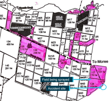
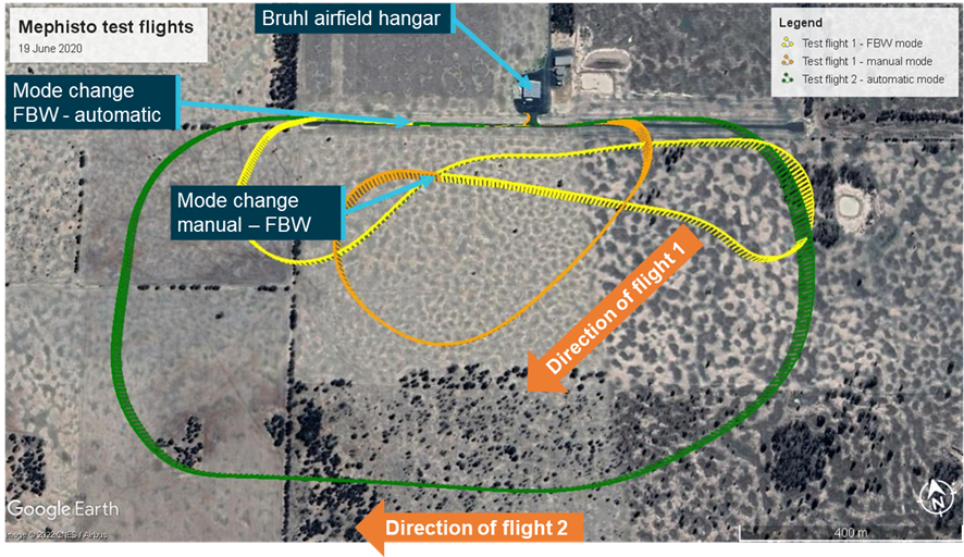
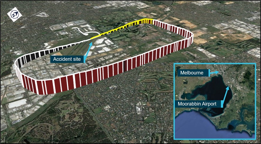
Late in the evening of 13 July 2023, the Remote Pilot in Command (RPIC) and copilot of a Damoda Newton V2.2 Remotely Piloted Aircraft (RPA) swarm operated by the Australian Traffic Network Pty Limited (ATN) arrived at a pre-arranged launch site on North Wharf at Docklands, Melbourne, Victoria (Figure 1). They were to conduct a limited test of a swarm RPA display (drone show) which was to take place the following evening in support of a sporting event at the Docklands Stadium.
Figure 1: Operational area and launch site
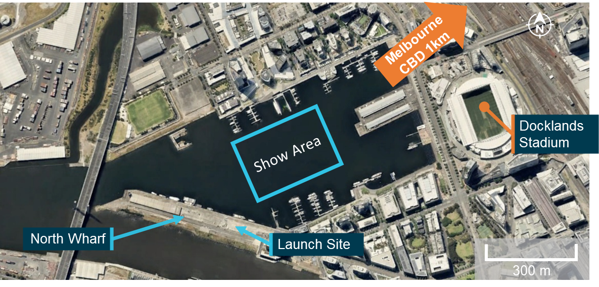
Source: Google Earth, annotated by the ATSB
The RPIC and copilot set out 10 aircraft [1] on the launch site and prepared the ground control station (GCS) to test the show program. The primary function of the flight was to test for potential interference from the launch site and the surrounding area. Shortly before the launch time, the RPIC identified that the wind conditions were well above the 15.6 kt limit that the aircraft could safely operate in and the test was downscaled to a hover test. The hover test involved 10 aircraft launching to a height of 10 m and hovering for a short time before landing.
The hover test was successfully completed with the GCS system recording minimal interference from the launch site. However, the RPIC reported that as part of this process the launch location programmed for the show was identified to be incorrect and that this location needed to be updated before the show the following evening.
Flight preparation
At approximately 1400 local time on 14 July 2023 the RPIC and copilot returned to the launch site to prepare for the show that was scheduled for 1830. On surveying the intended operating area, the RPIC identified that the mast of a boat moored on the wharf directly adjacent to the launch area was an obstacle for the swarm as it transitioned from the launch area to the show area. The mast was measured at approximately 15 metres tall, requiring the height of the swarm’s transition between the launch and the show to be increased.
Shortly after arriving, the copilot and RPIC were met onsite by 4 members of the show support crew. A fifth member, who was to assist in setting up and conducting safety checks on the 500 aircraft, was late. Following launch, the support crew were to monitor the exclusion zone [2] surrounding the show area for intruders.
The RPIC briefed the crew on several topics, including the operational plan for the display, the requirements for the launch grid and setting up the aircraft. The support crew then commenced setting out the launch grid and aircraft as per the show plan. The RPIC recalled that setting out the aircraft took slightly longer than anticipated due to the wind interfering with the process of measuring out the grid. During the set‑up the RPIC took multiple ground level wind readings with a handheld anemometer. The pilot recalled that these readings were returning 8–10 kt of sustained wind, with frequent gusts up to 12 kt.
Throughout the set‑up the RPIC was interrupted on multiple occasions by tasks normally assigned to the copilot. This included:
- additional briefings to support personnel
- multiple interactions with the client who wanted to confirm whether the show would be able to go ahead in the prevailing conditions
- interactions with other stakeholders and senior management of the operator’s company who were in attendance to view the show.
Setting up the grid took approximately 2 hours, after which the RPIC gave the support crew a 30‑minute break while they completed a walkthrough of the grid to ensure that the location and identification of each aircraft aligned with the set‑up plan.
At 1740, the RPIC started screen recording on the ground control station (GCS) computer. This recorded all activity on the screen of the GCS computer and audio within range of the computer’s microphone (see the section titled Ground Control Station).
Throughout the 50 minutes leading up to the show the recording captured interactions between the RPIC and copilot, and with support crew and stakeholders. It also recorded a range of operationally critical information. A detailed summary of events captured in the recording can be found in Appendix A, with key events summarised below.
At 1750 the first recorded wind speed reading was taken, giving 14 kt. At 1754 and 1817 further readings are taken at 12 kt and 14 kt respectively. At 1805 and following the 1816 reading the pilot and copilot discussed the prevailing wind conditions. The copilot stated that they believed that conditions were suitable to launch the swarm. In response, the RPIC identified that the readings they had were only at ground level and they had not tested for gusts at the intended height of the show. No further wind speed readings were taken and there was no further discussion of the wind speed recorded before the show.
At 1756 the RPIC was recorded dictating a voice to text message to the client’s representative with an update regarding the status of the show. They advised that the conditions were on trend with the forecast and they expected the show to go ahead at that point. At 1816 the RPIC identified that the representative had asked them for an update by 1815 as to whether the show would go ahead. At 1817 the RPIC was recorded dictating a further text message to the client that they were good to launch.
At 1759 the RPIC identified that to reprogram the show position to avoid the boat mast in front of the launch area required the assistance of another company pilot as they had not used that software functionality before. However, they were unable to contact the other company pilot for a further 8 minutes, despite prearranging for them to be available at 1800 to assist.
Between 1807 and 1817 the RPIC and the other company pilot went through the process of moving the show, performing the show virtual preview and interpreting the results of the preview. The RPIC applied the relevant correction to the show position, increasing the show height and moving the show to the left. The RPIC identified that the increased show height now exceeded the 120 m limit of the approval, but the other company pilot identified that the surrounding buildings provided some shielding. The RPIC elected to continue the show.
At 1817, following the completion of the show repositioning, the RPIC identified that they needed to work through the pre‑flight checklist prior to launch. The pilot and copilot worked through the items on the pre‑flight checklist. On multiple occasions they are interrupted by external communications from stakeholders and support crew.
At 1827 the RPIC instructed the copilot to make an airband broadcast in accordance with the pre‑flight checklist. The copilot questioned the need for the broadcast but was overruled by the RPIC and made the relevant transmission. The RPIC then completed the verification that the show program had been successfully uploaded to all 500 aircraft. At 1829 the copilot read out the last pre‑launch items on the checklist and the RPIC confirmed that they had been completed.
Flight
Launch
The aircraft were programmed to take off and ascend into a hover in a series of 10 layers of 50 aircraft (Figure 2). The aircraft would then move out over the water transitioning into the show area flying through a series of waypoints to make the relevant patterns of the show before returning and landing back on the grid. The whole show was planned to take about 10 minutes from take-off to return.
At 1830:15 the RPIC commanded the show to launch on the GCS. Following a 10 second countdown the aircraft powered up and the take‑off sequence commenced. The aircraft took off as programmed, with the 10 layers of aircraft stacked over the take‑off grid (Figure 2). However, 15 seconds after the first aircraft launched the GCS recorded 45 aircraft with errors, indicating that aircraft were out of position. Over the following 30 seconds the GCS recorded a further 78 aircraft showing as out of position.
Transition to the show area
At 1831:11 the swarm commenced its transition into the show area, but within 30 seconds more than half of the aircraft in the show were indicating errors, most for being out of position. At 1831:43 and 1831:48 the RPIC attempted to command the swarm to loiter, the first attempt was unsuccessful as they had not selected the aircraft to send the command to. The second attempt was successful with the loiter command reaching all the aircraft that were connected to the GCS computer.
At approximately the same time as the second loiter command was issued, multiple aircraft presented with critical errors indicating an autopilot failure. This was shortly followed at 1831:55 by the RPIC identifying that there was a ‘fly‑away’. Further errors of varying severity levels continued to present on the GCS. After confirming that the copilot had the fly‑away aircraft under their control, the RPIC directed the copilot to disarm[3] that aircraft.
By this time over 400 aircraft were presenting errors on the GCS. Between 1832:30 and 1832:50 the GCS rapidly lost connection to almost 400 of the aircraft in the swarm. When the connection was lost aircraft were in multiple different modes, with many showing loiter as per the RPIC’s command, some attempting to return to the launch area and others, predominantly those with critical errors, showing land in place.
Of the remaining aircraft connected to the GCS, 7 aircraft were attempting to continue with the show, which the RPIC then commanded to return home, while the remainder were indicating varying levels of errors.
Nine minutes and 56 seconds after the show was commanded to launch, the last operational aircraft returned to the launch point.
Divers contracted by the operator attempted to recover the aircraft from the harbour over the following days. The divers recovered 236 of the 427 aircraft that entered the water, with 191 unrecovered.
Figure 2: CCTV footage of show
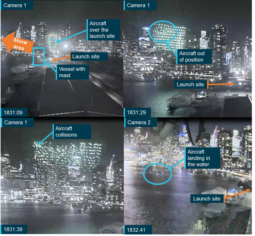
Source: City of Melbourne, cropped and annotated by the ATSB
Context
Aircraft information
Overview
The swarm consisted of 500 Newton V2.2 remotely piloted aircraft manufactured by Shenzhen Damoda Intelligent Control Technology Co., Ltd. (Damoda).
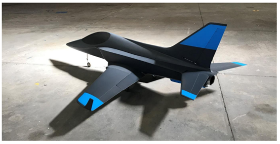
The Newton V2.2 is a quadcopter designed specifically for light show operations (Figure 3). It measured 360 mm square, sat 109 mm high, and weighed 725 grams. Mounted centrally on the bottom of the aircraft was a single colour‑changing LED light outputting a maximum of 16 watts. With a single battery the aircraft was designed for a show time of between 16 and 18 minutes and with a maximum hover endurance of approximately 26 minutes. The number of aircraft within the swarm could be varied depending on the individual show requirements, up to a maximum of 1,024.
Figure 3: Damoda Newton V2.2
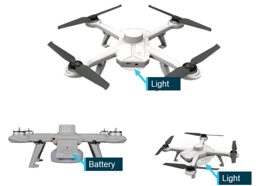
Source: Operator, annotated by the ATSB
To conduct a show each aircraft was programmed with a series of timed waypoints and light colour changes. The aircraft operated independently through these waypoints with minimum separation distances of approximately 1.5 m during the show. Aircraft were not fitted with sensors to allow independent collision avoidance, relying on positional and time‑based accuracy to prevent collisions.
The aircraft were installed with a firmware package to enable operations. Due to the flight critical nature of the firmware, the operations manual required a flight test be conducted following a firmware update and that a record of this flight be made in the aircraft maintenance log.
Batteries
For the show each aircraft was fitted with a removeable Lithium Polymer (LiPo) battery that weighed 300 g and had a maximum energy capacity of 42.56Wh. Upon installation the aircraft had a red button that would protrude from the body of the aircraft to indicate that the battery was mounted correctly. For a swarm of 500 RPA these batteries equated to a total energy capacity of 21.28kWh.
Aircraft limitations
The manufacturer’s wind speed limit for the Newton V2.2 was 8 m/s (equivalent to 15.6 kt or 29 km/h), this wind limit was common to all Damoda aircraft. In addition to the wind speed limit the aircraft also had an ingress protection or IP[4] rating of 63. This rating indicated that the aircraft were dust tight and could resist water spray but were not designed to operate in rain or be immersed in water and they would not float.
Aircraft positioning
Due to the close proximity of the swarm aircraft, uncorrected GNSS position information was not sufficiently accurate. To obtain high accuracy GNSS positions the aircraft were connected to a network containing a Real Time Kinematic (RTK) receiver. By using an independent stationary receiver in proximity to the aircraft the positional accuracy can be improved from several metres to centimetres as required for show operations. At 1822, 8 minutes before the show was due to launch, all aircraft were showing between 23 and 28 satellites connected and a high accuracy RTK position fix.
Prior to the show, the operator set up a spectrum analyser to identify potential interference in the GNSS signal that may cause the aircraft to malfunction or be out of position. The RPIC advised that prior to the show no abnormalities were identified in the signal that could have affected the aircrafts’ ability to accurately position themselves.
GNSS spoofing
GNSS spoofing is the process of tricking a receiver into reporting an incorrect position. Spoofing a signal requires 2 steps, first the incoming signal to the receiver needs to be jammed and then the receiver must lock onto an independently generated false signal providing incorrect information. In the lead‑up to the display the GCS computer shows the position of each aircraft on the ground and in flight. These positions were shown over a base map and corresponded with locations recorded by CCTV footage (Figure 4). If the signal to the aircraft had been spoofed these locations would not have aligned.
Figure 4: Comparison of GCS and recorded aircraft positions
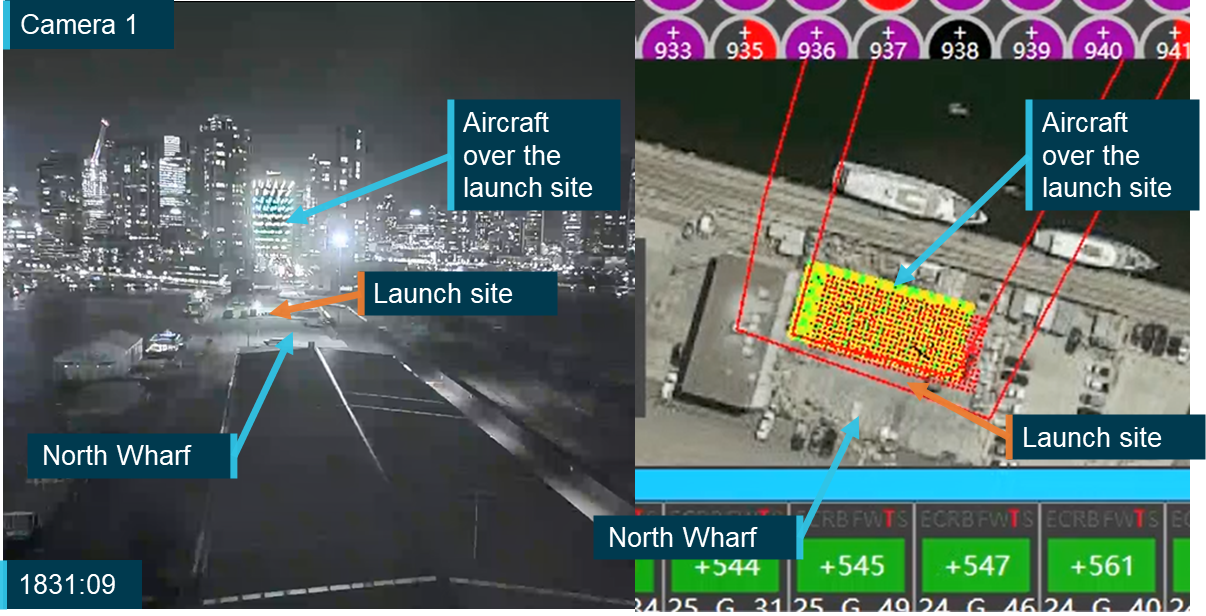
Note: The satellite basemap image as shown on the GCS is not an accurate representation of the actual structures around the launch site. This image was taken earlier in 2023 but the ATSB was unable to confirm the exact date. Source: City of Melbourne and operator annotated by the ATSB.
Aircraft modes
The Newton V2.2 could be operated in 6 different flight modes, G (guided), S (stabilised), L (loiter), R (return to launch), LD (land) and AH (altitude hold). A mode could be selected for an individual aircraft, it could be commanded for all aircraft in the swarm or it could be automatically changed by logic within the aircraft in the event that certain conditions were met. Manual mode changes could be commanded via the ground control station computer or a backup manual controller (see the section titled Ground control station).
In guided mode the aircraft was positioned based on the corrected GNSS position and transited through a series of pre‑programmed waypoints, before returning to the launch location.
In stabilised mode the GNSS positioning was disabled and the aircraft was manually flown using the hand controller. This mode was used if the aircraft had an error that rendered it unable to return to home automatically.
In loiter mode the aircraft held both lateral and vertical position until a further command was provided by the pilot, either via the GCS or using the hand controller.
In return to launch (RTL) mode the aircraft automatically tracked back to a position over the launch location. As the aircraft did not have obstacle avoidance sensors, this option was preferred only for individual or small groups of aircraft as commanding RTL for the whole swarm was likely to result in multiple aircraft collisions and loss of aircraft.
In land mode the aircraft landed directly below its current location.
Aircraft errors
The Newton V2.2 had 6 error modes that could be presented on the ground control station. These were:
- EKF (autopilot failure)
- W (waypoint issue)
- B (battery voltage was low)
- F (aircraft had breached the geofence)
- T and S (Too far and Static) both indicated that the aircraft was not at the planned position. Too far indicated that the aircraft was more than 0.8 m from its target position. The distance from the target position required to activate a static error was not identified in the aircraft documentation.
These errors were broken into 3 categories depending on the required pilot response when they are presented.
- EKF or W errors required the pilot to return the aircraft to launch.
- B error - the aircraft should activate RTL automatically.
- F error - the aircraft would automatically activate RTL and re-enter the geofence. If it did not return within the geofence the motors would be automatically shut down.
- T and S errors were for information and monitoring. The pilot was only to intervene and manually activate RTL if the distance between the planned and actual locations continued to increase.
The display of these errors on the GCS is discussed further in the section Flight control software - Warnings. The RPIC identified that there were up to 10 aircraft presenting with EKF errors, and that they had never experienced more than one EKF error simultaneously.
Fleet
At the time of the occurrence the operator had a total Damoda V2.2 fleet of 1,136 aircraft registered with the Civil Aviation Safety Authority (CASA). The first 515 of these were registered with CASA at the end of October 2022. The remaining aircraft were registered in April of 2023, shortly after their purchase.
Along with these additional aircraft, the operator also purchased additional support equipment for a second complete GCS layout. This enabled the operator to either operate 2 independent fleets of 500 aircraft or to combine the 2 fleets for a single show of up to 1,024 aircraft. When the operator purchased the additional aircraft, it was supplied with the latest version of the aircraft firmware and the manufacturer’s latest GCS software (see the section titled Flight control software).
Ground control station
The ground control station (GCS) consisted of 4 elements:
- a laptop computer running Damoda’s flight control software
- a Wi-Fi network to which all the aircraft were connected, enabling communications and data transfer between the aircraft and flight control software before and during the show
- a differential ground station for real time correction of the GNSS signal
- a spectrum analyser used to identify abnormalities or issues in the frequency bands that the aircraft and the GNSS signal were operating.
These elements were brought to the show location by the operator and were set up by the flight crew.
Flight control software
Operating on a laptop computer, the flight control software provided all command and control actions for the swarm through the local network. Common to all Damoda aircraft types, the software allowed flight crew to monitor the status of all aircraft before and throughout the show. It was used to upload, manipulate and test the proposed show, control the aircraft either through the software itself or by tethering them to the hand controller.
The flight control software also displayed errors and warnings affecting the aircraft or the software. The flight control software was not used for the development of the show flight paths or ‘drama’. This was completed in a different software package and a drama file containing the show flight paths for each aircraft was imported into the flight control software for uploading to the individual aircraft.
When the operator received the first 500 aircraft in October 2022 these were provided with version 2 of the manufacturer’s flight control software. Prior to the acquisition of the operator’s second 500 aircraft in April 2023, the manufacturer introduced an updated version of the flight control software (version 3), and this was provided to the operator, along with an updated version of the aircraft firmware.
Wind speed monitoring
A wind monitoring function was introduced with version 3 of the flight control software. This function displayed the maximum wind speed and direction encountered by aircraft in the swarm, in the upper right corner of the screen (Figure 5). To provide a reading, at least one aircraft had to be active and connected to the GCS software.
The wind monitoring function remained visible and its position constant on the screen throughout the operation of the GCS. Other functionality could be selected or deselected depending on the pilot’s information preference. Wind speed and direction were calculated and displayed in real time through the interpretation of aircraft bank angle and motor speed, combined with the planned and actual positions of the aircraft.
When the wind speed limit was exceeded, there was no audible, visual or tactile alert presented to the pilot. As such, the flight crew needed to actively monitor the parameter to be aware of an exceedance of the wind speed limit. Figure 6 shows the wind speed indicator at 3 moments during the show with the wind speed below, just above and significantly exceeding the 8 m/s published wind speed limit of the aircraft.
Figure 5: GCS software display with wind speed readout highlighted
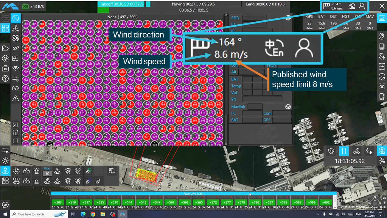
Source: Operator, annotated by the ATSB
Figure 6: Wind speed display below, just above and significantly exceeding the wind speed limit
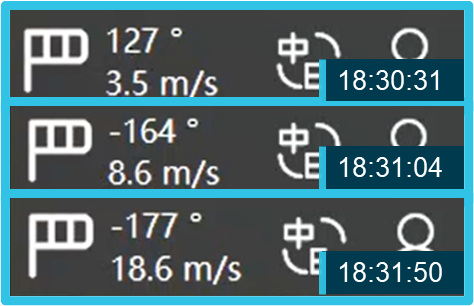
Source: Operator, cropped and annotated by the ATSB
The flight crew advised that at the time of the show they were not aware that this functionality was available to them. The RPIC reported that they only became aware of it when they were reviewing the incident with another one of the operator’s pilots who identified the indicator to them. The RPIC stated that if they had identified this information at the time of the show then they would have likely terminated the show when the wind speed limit was reached.
Warnings
The GCS software could present 2 different types of warnings depending on whether an individual or multiple aircraft were affected.
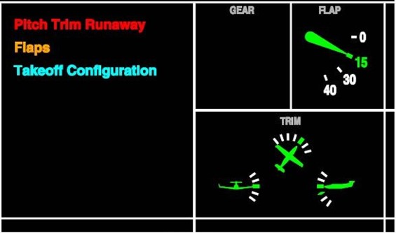
Errors related to individual aircraft presented on the GCS computer in an individual box as shown in Figure 7. These boxes showed the aircraft identifier, the error or errors and the mode the aircraft was operating in. They were then grouped by colour coded category depending on the required pilot response. Errors requiring immediate action were coded red, those that resulted in an automatic RTL were coded orange and those that only required monitoring were coded blue.
Where an aircraft showed errors from multiple different categories the aircraft was placed in the highest category of urgency encountered. Figure 8 shows all 3 of the categories appearing on the GCS for this occurrence, shortly after the aircraft transitioned towards the show area.
Figure 7: GCS screenshot showing individual aircraft errors
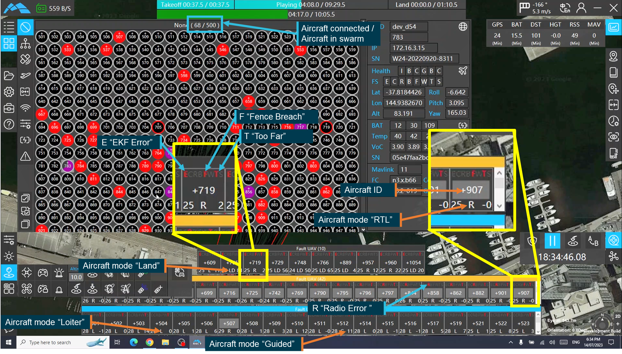
Source: Operator, annotated by the ATSB
Figure 8: GCS recording showing the 3 error categories as they appeared on the night of the show
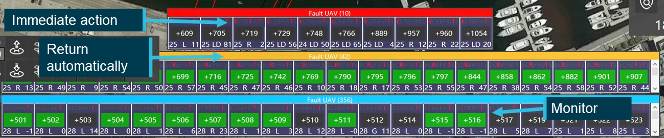
Source: Operator annotated by the ATSB
Errors that affected multiple aircraft were presented as a pop‑up over other windows on the GCS screen (Figure 9) and required acknowledgement before any other action could be taken. These warnings were presented in instances such as a failure of data to successfully upload to aircraft or failure of a command to reach the aircraft.
Figure 9: GCS screenshot showing a multi-aircraft warning pop‑up
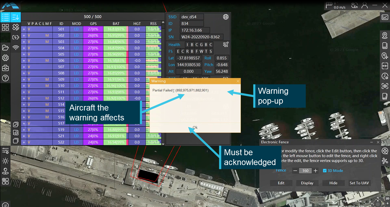
Source: Operator, annotated by the ATSB
Both types of warnings relied on data processed by the GCS to display the relevant information to the pilot. The errors were then presented in such a way that the pilot could rapidly interpret the meaning and respond appropriately.
Adjusting the show
The GCS software had the capability to adjust the position, height and orientation of the drama file to ensure that the flight paths could be executed safely. The flight crew had multiple options for making the adjustment, which could be used independently or simultaneously. They could change the height or position of the whole drama file or they could adjust the launch and landing profiles, which changed the position and altitude that the aircraft moved to before they transitioned into the show area.
Due to the boat mast hazard the RPIC, in consultation with one of company’s other pilots, elected to adjust the position of the transition into the show area by increasing the height by 11 m and moving all aircraft 2 m to the left (Figure 10). To accommodate for these changes the total height of the show was also adjusted up by 8 m taking the maximum show height to 126 m.
Figure 10: Drama adjustment functionality as set by the RPIC
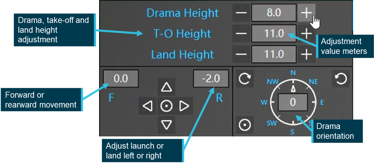
Source: Operator, annotated by the ATSB
Setting the geofence and exclusion zone
The geofence is a polygon made of a series of GNSS locations surrounding the show area (Figure 11). It was manually created in the flight control software and then uploaded to the aircraft. Once in flight, if an aircraft passed through the geofence it automatically activated the RTL mode to bring it back inside the geofenced area and return to land. If the aircraft remained outside the geofence then the motors were shut down and the aircraft fell to the ground or water uncontrolled.
Figure 11: Development and placement of Geofence

Source: Operator, annotated by the ATSB
The flight control software had a measurement feature that allowed the operator to identify and measure approximate distances over the base map. This allowed the determination of the size of both the geofence and the subsequent size of the exclusion zone (see the section titled Exclusion zone).
Hand controller
Swarm operations are conducted autonomously with the aircraft moving through a series of pre‑programmed waypoints or in the relevant failsafe modes. In the event of a system issue or error that prevented the automated system from effectively controlling the swarm, manual control could be taken using a hand controller. The controller allowed the operator to fly the swarm, command mode changes and activate relevant failsafe modes on the aircraft. For the hand controller to be used it must be tethered to the relevant aircraft in the swarm. It could be tethered to all aircraft in the swarm or to certain aircraft independently.
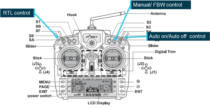
The manual controller employed by the operator was a VANTAC Taranis hand‑held controller, manufactured by FrSky. The VANTAC (Figure 12) was a programmable, 24 channel, 2.4 GHz transmitter that could be used to control a range of remote devices, including RPA. The controller had 8 programable control switches, (6 3‑position and 2 2‑position) that the user could assign to modes or operational settings. In support of the Damoda swarm operations the switches were assigned as per Figure 12. The mode switch allowed the operator to change the mode between land, loiter and stabilised modes. As part of the operator’s pre-flight checklist the throttle (vertical movement on the left control stick) on the controller was to be set to 50% so that if the controller was required the aircraft would have sufficient power to hover.
The emergency kill switch was a 2‑position switch. When activated it immediately shut down the motors, causing the aircraft to fall to the ground. This was the command that the copilot implemented once the RPIC instructed them to disarm the fly‑away aircraft.
Figure 12: FrSky VANTAC Taranis controller
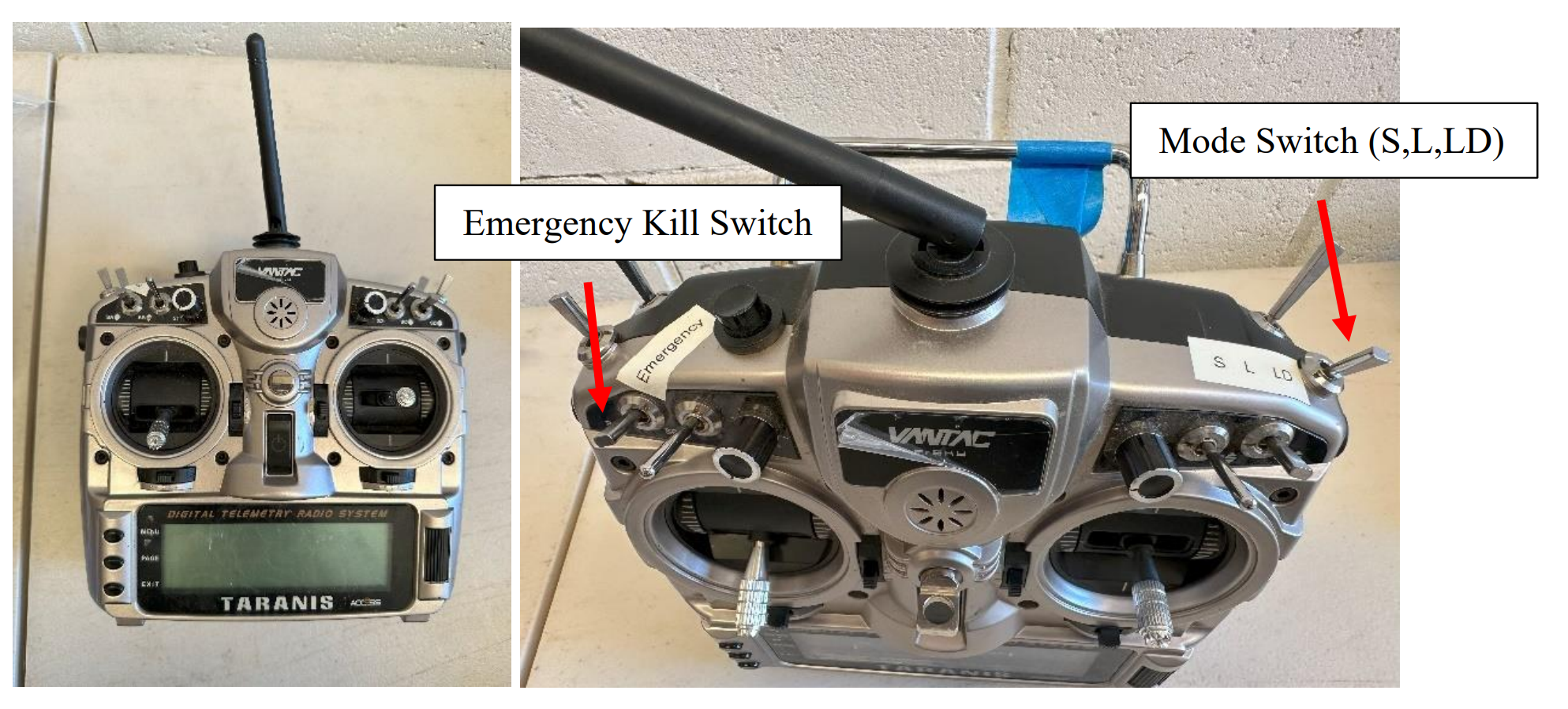
Source: Operator
Crew information
The operator’s manuals listed the crew for a light show operation in 3 distinct groups, all under the oversight of the RPIC, as follows:
- flight crew, responsible for the safe setup and operation of the fleet of drones
- ground/support crew, assisted in the set-up of the fleet and operational area and monitoring the ground and airspace around the show for potential intruders
- additional security or other personnel involved in securing the operational area, such as water police for a show over water.
Flight crew
For light show operations involving up to 500 aircraft the company operations manual required a flight crew of 2 – a mission commander (RPIC) and a copilot. The CASA permission for the operation (see the section titled Operational approval) listed specific pilots who were approved to operate more than one RPA at a time. The CASA permission did not specifically require a second pilot, however the operator’s manuals contained a requirement for a 2 or 3 pilot operation depending upon the swarm size.
Remote pilot in command
The RPIC was authorised and qualified to act as the mission commander for the operation that was being undertaken. They held a Remote Pilot License (RePL) for multi‑copter operations up to 25 kg. Upon joining the operator in October 2022, they had completed the Damoda training program and subsequently been endorsed by CASA to operate more than one RPA at a time.
At the time of the operation the RPIC had approximately 6 hours on type consisting of 32 training or operational shows varying in size from 10 to 1,050 aircraft conducted at a range of locations, including over water, and in both day and night conditions. The RPIC’s most recent show flight was the rehearsal for the Docklands operation, which was carried out 4 days prior to the show.
The RPIC held ultimate responsibility for the safe operation of the show in accordance with the relevant permissions and operator’s manuals. The operations manual outlined the specific responsibilities of the RPIC to include but were not limited to:
• Conducting an operational safety briefing on items relevant to the RPA operation.
• RPA crew co-ordination.
• Ensuring the RPA is in CASA approved airspace.
• Ensuring operations are conducted in accordance with company operating procedures including the JSA [job safety assessment] and Flight Authorisation.
• Maintaining communication with the RPA crew throughout the entire operation using Local Comms Handheld Radios.
• Confirming responsibilities of all flight crew members
• Reviewing the show design and verify operational area, exclusion area, and minimum drone separation distance (1.0 m) prior to flight.
• Confirming proper set-up of base station.
• Operation of the RPA.
• Post-flight data recording.
• Confirm all crew fitness for duty.
• Reporting incidents to the Chief Pilot.
Copilot
The copilot for this operation was authorised and qualified to operate in the role of copilot. They held a RePL for multi‑copter operations up to 25 kg and had completed the operator’s Damoda training program following the introduction of the aircraft type in October 2022.
The copilot had previously completed 17 lightshow training flights operating in either the RPIC or copilot role, the most recent of which was as a copilot 3 days prior to the occurrence flight at Sydney Olympic Park. The operator’s flight logs identified that prior to that operation they had not completed a show in more than 6 months. The copilot had not been endorsed by CASA as qualified to operate as mission commander (RPIC) in one‑to‑many operations, however under the operator’s manuals this was not required to operate in the role of copilot.
The copilot’s role as outlined in the operator’s manuals was to assist the RPIC in the conduct of the show. The manual delegated specific responsibilities to the copilot. While not specifically stated in the manual, one of the aims of this was to reduce the RPIC’s workload. The responsibilities of the copilot included:
• conducting an operational safety briefing on airspace items
• management of stakeholders
• management of show support crew
• monitoring operating area Airband VHF frequencies throughout the entire operation
• broadcasting on VHF frequency when needed
• immediately advising Mission Commander of any relevant airspace traffic
• show timing
• co-ordinating incident response
• assist the Remote Pilot in Command and be co-located during the show unless attending to an emergency
• activate emergency procedures in event of RPIC incapacitation
• Hold direct communication with the all crew throughout the entire operation using Local Comms Handheld Radios (or co-location).
• Visual observation of swarm
• Alert of drone flyaway
• Control of drone flyaway Drones IDs 1-500
The copilot was also the operator’s chief remote pilot (CRP). As such, they had overall responsibility for the RPAS operation, including the approval of operations planned by the other pilots. The copilot had completed training on the V2.2 aircraft and GCS software when it was introduced, however they stated that they normally left the planning and operation of the shows to the other pilots who were more proficient in swarm operations. This allowed them to focus on other areas of their role in the organisation.
Due to staffing changes at the operator (see the section titled Staffing changes) the chief remote pilot had been brought into this operation as a copilot. As they were not endorsed by CASA, they could not assume the role of RPIC.
Ground crew
In support of the flight crew the operator’s manual required that one ground crew member be present for every 100 aircraft within the display. Under the operations manual these crew members were responsible for a range of tasks. These included:
- ground handling of the RPAs
- pre- and post-flight checks of the RPAs
- battery management
- monitoring of the ground and airspace around the show area for potential breaches
- maintaining direct communications with the flight crew throughout the entire operation.
The operator sourced ground crew members from a labour hire company. Ground crew members were briefed by the RPIC and required to complete a consent and compliance declaration acknowledging that they understood their role. Once briefed by the RPIC the management of the show support crew was the responsibility of the copilot.
Additional personnel
As this show was to be conducted over water, the operator was required to ensure that water traffic was maintained clear of the show area exclusion zone. To enforce this zone the operator had engaged vessels from Parks Victoria, Victorian water police and a private contractor to monitor the show area perimeter. Communications between these vessels and the flight crew was maintained by UHF radio.
Multi-crew operations
Cockpit gradient
A cockpit or authority gradient refers to how balanced power and decision‑making authority is within a team. Authority is not necessarily defined by experience or competence in a role but may be through the role that a person holds (SKYbrary, 2025). Where a cockpit gradient is too steep, team members may not be willing to challenge or express concerns over a leader’s decisions, and where too shallow it can slow decision‑making processes.
A negative gradient is where a team member in a subordinate role has more power or authority than the team leader. This can undermine the team leader’s authority and lead to the leader deferring to, or placing additional weight on, that team member’s opinions or ideas.
In crewed operations, to be endorsed to fly multi‑crew, pilots must undertake multi‑crew coordination (MCC) training. Part of this training required the candidate to demonstrate effective management of flight deck gradient for tasks that were being performed. Neither the CASA approval nor the operator’s documentation required this or equivalent training for swarm operations.
Operator information
Operations manual
The operator maintained an operations manual and operations library in accordance with the requirements of Part 101 of the Civil Aviation Safety Regulations 1998 (CASR); both had been approved by CASA. The operations manual contained the operator’s overarching processes and procedures and outlined various regulatory compliance requirements. The operational library contained more specific aircraft information and operational processes.
For example, the operator’s manual contained information about the conduct of RPAS display operations, however the specific process for carrying out the pre‑show checklist was contained in the operational library. Similarly, the basic and overarching emergency procedures were contained within the operations manual but specific responses and processes for different emergencies were in the operational library.
The operations manual outlined that the chief remote pilot was responsible for all operational matters and remote pilot training affecting safety. This included:
- ensuring that operations were conducted in compliance with relevant regulations
- responsibility for applications, permissions and approvals to facilitate operations
- maintaining a reference library of operational documents
- developing checklist and procedures relating to flight operations.
Checklists
To support show operations using Damoda aircraft the operator maintained and utilised several checklists contained within the operations library. The show day and flight checklists were the primary documents used by the crew in preparations for a show. There were different versions of these checklists depending on whether more or less than 500 drones were being used in the show.
For a show of up to 500 drones, the show day checklist consisted of 10 items, taking the crew through the set‑up of the GCS and the laying out of all drones in preparation for the show. It also included guidance on the set‑up of the network and RTK equipment and environmental monitoring including electromagnetic and wind conditions.
The final item on this checklist (Figure 13) was for a weather inspection. This item required the pilot to check the current weather forecast and measure the wind speed at 5‑minute intervals for the 30 minutes before the show start ‘if the pilot has capacity’. The checklist did not identify a specific location where these wind readings are to be taken. The checklist was dated 7 March 2023, which was before the introduction of the wind management plan and weather drone (see the section titled Wind management plan).
Figure 13: Item 10 on the operator’s show day checklist
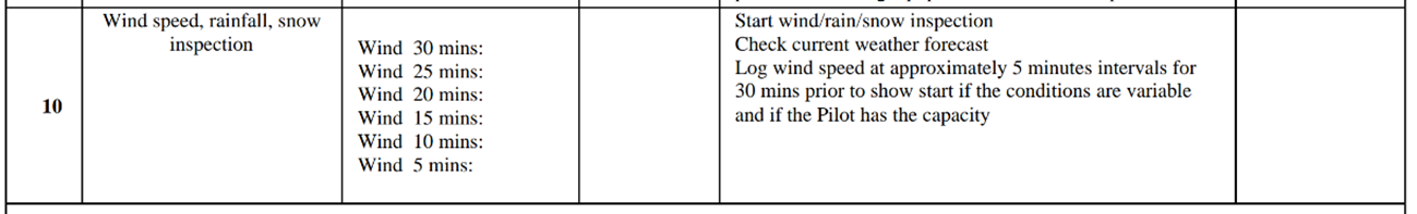
Source: Operator
At interview both the RPIC and copilot identified that this checklist was available to assist them in the lead‑up to the show. The RPIC stated that they and other pilots were familiar with the content and they did not always refer to the checklist during preparations for the show.
For a show of up to 500 drones the flight checklist consisted of 20 items taking the flight crew through the set‑up of the aircraft and GCS equipment, a review of the emergency procedures and final checks. Item 17 was the final item before launch and it required the RPIC to consider their confidence in the fleet and assess the overall risk factors before deciding whether to launch the show. The RPIC stated that the flight checklist was mandatory and was always used in the lead‑up to the show.
Emergency procedures
The operator’s manuals outlined the procedures in the event of an emergency during the swarm display. It defined procedures for a range of non‑swarm related emergencies including fire on the ground, crew medical event and non‑cooperative traffic (aircraft or bird) interacting with the swarm.
The general response to any of these emergencies was to respond to the immediate threat (if required) and then place the swarm on the ground as quickly and safely as possible either using an RTL or land command sent to all aircraft or manually controlling aircraft to the ground.
The operator maintained specific emergency procedures for aircraft producing EKF (autopilot failure) and W (waypoint issue) errors. These errors required an immediate response from the pilot to select RTL and if the RTL command failed the aircraft were to be flown back manually using the hand controller.
Item 2 of the operator’s flight checklist required that the RPIC and copilot reviewed the emergency procedures prior to flight. The GCS recorded that the RPIC stated that the response to these errors would be to RTL, take control of the aircraft manually and if neither of these were successful, land the aircraft in the water.
In response to this occurrence, the RPIC activated the emergency procedure for EKF errors and fly away aircraft. While initially the RPIC activated a loiter command, at that time neither the fly away nor the first EKF error had occurred. When these occurred the RPIC instructed the copilot to control and then deactivate the aircraft and attempted to RTL each aircraft showing an EKF error on the GCS.
Training and checking
With the introduction of the Damoda aircraft all the operator’s pilots, including the copilot (CRP) undertook initial training with the manufacturer’s Australian agent. The CRP identified that there were some gaps in the training so the operator’s pilots undertook further in‑house familiarisation and testing with the show software to understand the relevant capabilities and features.
When version 3 of the GCS software was introduced, no formalised training was undertaken with the manufacturer or its Australia agent. The operator and RPIC reported that the manufacturer had provided a document with installation guidance and some differences between the old and new versions of the software. They further identified that prior to starting operations with the new software the pilots undertook familiarisation with it, identifying updates to existing features and some of the new features.
There was no documented process for ensuring that all pilots had the same level of competence or were aware of all the relevant features of the software.
Prior to commencing show operations, the RPIC was required to complete the operator’s internal training program and be checked by CASA for approval to operate multiple aircraft simultaneously. The training syllabus for operations using the Damoda aircraft involved 8 sessions. The first required the pilot to demonstrate correct set‑up and operation of all the show hardware, including the GCS and aircraft.
The following sessions involved incremental increases in the number of aircraft from a single aircraft through to a 1,050 aircraft flight. Each session required the pilot to identify the relevant configuration, set‑up and crewing changes for the number of aircraft being operated. The CASA check for approval to the operational instrument was built into this training syllabus and was completed as part of session 7. Session 8 was a final demonstration flight with 1,050 RPA.
The operator’s manual required show‑qualified RPICs, copilots and ground crew members to undertake proficiency checks to ensure that they were operationally capable. Proficiency checks covered a range of items applicable to each of these roles. They were required every 12 months unless the candidate had carried out a minimum of 4 relevant light show operations in the last 12 months, whereby the time between the proficiency checks could be extended to 24 months.
The RPIC had joined the operator less than 12 months previously and had completed more than the required 4 light show operations as RPIC meaning that a proficiency check was not required until October 2024.
Proficiency checks were required for each aircraft type and additional proficiency checks were not required in the event of significant changes to the software.
Wind management plan
In response to a specific request from an earlier client the operator had developed a wind management plan. Introduced on 21 May 2023, the plan was ‘…to ensure the safe and successful execution of a drone light show event in windy conditions’. While initially developed for that specific client the plan made no specific reference to that client or event, generally identifying the set‑up and operational wind limits and specifying how weather could be monitored. The set‑up limit was 18 kt (9.2 m/s) measured 3 hours before the flight and the operational limit was 14 kt (7.2 m/s) measured 5 minutes before the flight. The wind management plan also contained higher level statements about how the use of certain aircraft, training of pilots, engagement with stakeholders, an emergency response plan and post‑event evaluation was used to achieve the purpose of the plan.
Despite containing operationally relevant information related to wind management and responses to adverse conditions the plan was only included in the event plan for the show and was not integrated into the organisation’s operational processes and procedures.
Version 1.1 of the wind management plan was dated 6 June 2023, approximately 5 weeks before the accident flight. The updated version increased the operational wind limit from 14 to 15.3 kt (7.2 to 7.9 m/sec) and introduced, at the RPIC’s discretion, the use of a weather drone to test the conditions in the show area before the show was launched. The plan did not detail how the weather drone could be used, but the CRP identified that it could be conducted with a separate aircraft or an aircraft from the swarm could be tethered to the controller and flown manually for the weather check. As with the earlier version, the updated version of the plan was only included in the event operational plan and not integrated into show processes and procedures.
The wind management plan did not refer to the wind speed readout on the GCS display.
The RPIC advised that they were aware of the wind management plan and that, to their knowledge at the time of the occurrence, it did not contain the option for the launch of a weather drone. They further stated that this was only introduced post this accident.
Staffing changes
In the weeks leading up to the show there were several staffing changes that impacted how the show was planned and carried out. Firstly, the operator’s chief executive officer (CEO) had left and this show was the first opportunity for the new CEO to see the company’s drone swarm operation in practise. Secondly, the operations manager, who had been the main point of interaction between the client and flight crew during show preparations had left the company and had not been replaced.
As a result of the departure of the operations manager, the RPIC had taken on this role and subsequently was involved in preparation of multiple shows, including the Docklands show. This included liaising directly with the client and other stakeholders. The RPIC stated that having the pilot operating the show involved in client interaction during operational planning was normally avoided. This was to ensure that the RPIC on the night could focus on operating the show and not have to worry about engaging with the client.
Normally, once a show had been planned, contact with the client would be handed over to the copilot for them to manage on the night of the show. For this show that did not occur due to the already established relationship between the RPIC and client.
The reduction in team size brought about by the operations manager’s departure reduced the personnel available for this show. Subsequently the CRP who was copilot‑qualified, but stated that they weren’t ‘recent’ in the operation, stepped into the role of copilot. The RPIC commented that this resulted in a different dynamic between the RPIC and copilot than if the copilot had been more experienced.
Operator’s review
Following the accident the operator conducted a review into the occurrence and identified the following:
- The flight crew did not consider the conditions in the show area at altitude.
- RPIC was under unrealistic pressure to complete the show in the allotted time.
- The copilot’s limited experience increased pressure on the RPIC.
- Requirement to move the show reduced time available for show preparations.
- The RPIC had significant confidence in the reliability and functionality of the operational fleet.
Operational information
Operational approval
In Australia RPAS operations are governed by Part 101 of the CASR. Under regulation 101.300 a person may not operate more than one RPA without a specific approval from CASA. On 12 May 2023 CASA issued a 12‑month approval for the operator and specified pilots to operate more than one RPA at a time and at night, subject to a series of conditions. Some of the conditions listed on this approval were that the:
• operator must have an active notice to airmen (NOTAM) advising when and where the operation was taking place
• operator must operate in accordance with their operations manual
• operator may only operate Damoda multirotor aircraft up to 750 g
• RPA must have appropriate failsafe functionality in the event the data link to it was lost.
• operator must maintain an appropriate exclusion distance to non-essential personnel as outlined in the specific revision of their operations library.
Provided that these conditions could be met, the operator was permitted to plan shows at any location in Australia.
Show planning
Once a potential show location had been identified, an operational self‑assessment was to be carried out on the site using the process outlined in the operations library. The assessment was to include hazards within the operational area, including the show airspace, the launch and recovery area and the traversal airspace between these 2 areas. The assessment also determined the exclusion zone requirements.
The self-assessment required consideration of the access to both the ground and airspace in these areas, clearance and obstacles, the potential for RF interference, ground topography and other potential users. The manual specifically identified that waterways were a preferred operational area as the water provided a natural barrier to public access. Waterways without vessel access were preferred, however where vessel access was possible then an exclusion zone needed to be set up and enforced by the relevant authorities.
Docklands
The show planning for the Docklands operation was carried out by the RPIC and one of the operator’s other pilots. Part of the planning process was engagement with the harbour authority to organise a harbour closure and enforcement of the exclusion zone around the show. In the days leading up to the show, the operator requested that the 15‑minute closure window for the show be moved later due to forecast wind conditions. The operator advised that the harbour authority had stated that this was not possible.
Event operational plan
The event operational plan contained all the relevant information that the crew required to conduct the show, such as timings, location, relevant stakeholder contact details and plans for traffic and crowd control. Listed as attachments to the operational plan were 5 appendices (labelled A through E). Appendix A was the wind management plan. The event operational plan did not specify which version was attached, however at the time v1.1 was current. Appendix D contained the operator’s risk assessment. This document identified the loss of aircraft into the water as a hazard that required treatment. Most of the treatments were related to management of batteries and inspection of aircraft, the final treatment was the availability of divers onsite to recover any RPAS that were lost into the water.
The event operational plan and its appendices were available to the flight crew on the day of the accident. However, the RPIC reported that in the lead‑up to the show the crew would normally refer to the checklists rather than the event operational plan for relevant processes. In the 50 minutes leading up to the show the only reference that was recorded to the event operational plan was associated with obtaining the frequency for the nearby Essendon air traffic control tower.
Operational area
Victoria Harbour is located approximately 1 km south‑west of the Melbourne CBD. The area surrounding the harbour is a mixed residential and commercial precinct with the Docklands Stadium on the northern end and several high‑rise buildings adjacent to the harbour, with the tallest being approximately 140 m.
South of the harbour the Bolte Bridge crosses the Yarra River with two 140 m tall support towers. The selected launch site had previously been used by another operator to launch a swarm display. That display had encountered issues with magnetic interference close to the ground, which was believed to be due to the large volume of steel reinforcing of the concrete at the launch site associated with its previous use as an operational dock.
The operator had identified this as a potential hazard and expected that there may be some magnetic interference with the aircraft, however there were minimal impacts identified in the GCS recording or reported by the flight crew prior to or during the initial launch of the swarm.
As shown in Figure 1 there were multiple jetties where pleasure craft were moored extending up to 90 m into the harbour. As the operator did not have access controls in place for these jetties, to ensure safety for anyone on them at the time of the show, they needed to be outside of the exclusion zone around the show area.
Exclusion zone
An exclusion zone ensures that, in the event of an aircraft operational issue, it will be contained and not pose a risk to non‑essential personnel. The zone is calculated from the geofence, based on the aircraft’s maximum operational speed and its wind speed limit. Therefore, an aircraft operating at maximum operational speed with a tail wind at the aircraft’s wind speed limit will still be contained. The exclusion zone was calculated at 50 ft operating height increments between 100 ft and 400 ft (maximum allowable show height).
Table 1, reproduced from the operations library, shows the calculated minimum exclusion zones for Damoda V2 aircraft between 100 ft and 400 ft.
Table 1: Damoda V2 minimum exclusion zones by aircraft height
| height of RPA | size of exclusion zone |
| 400 ft (121.92 m) | 70 m |
| 350 ft (106.68 m) | 61.4 m |
| 300 ft (91.44 m) | 54 m |
| 250 ft (76.20 m) | 45.9 m |
| 200 ft (60.96 m) | 39 m |
| 150 ft (45.72 m) | 31.3 m |
| 100 ft (30.48 m) | 23.9 m[5] |
Prior to setting the geofence, the pilot measured the distance between the edge of the show area and a publicly-accessible jetty on the opposite side of the harbour to be 62 m. The RPIC then set the geofence around the show area manually using a buffer of 8–15 m, resulting in an effective exclusion zone between 47–54 m (Figure 14).
Figure 14: Exclusion zone positioning
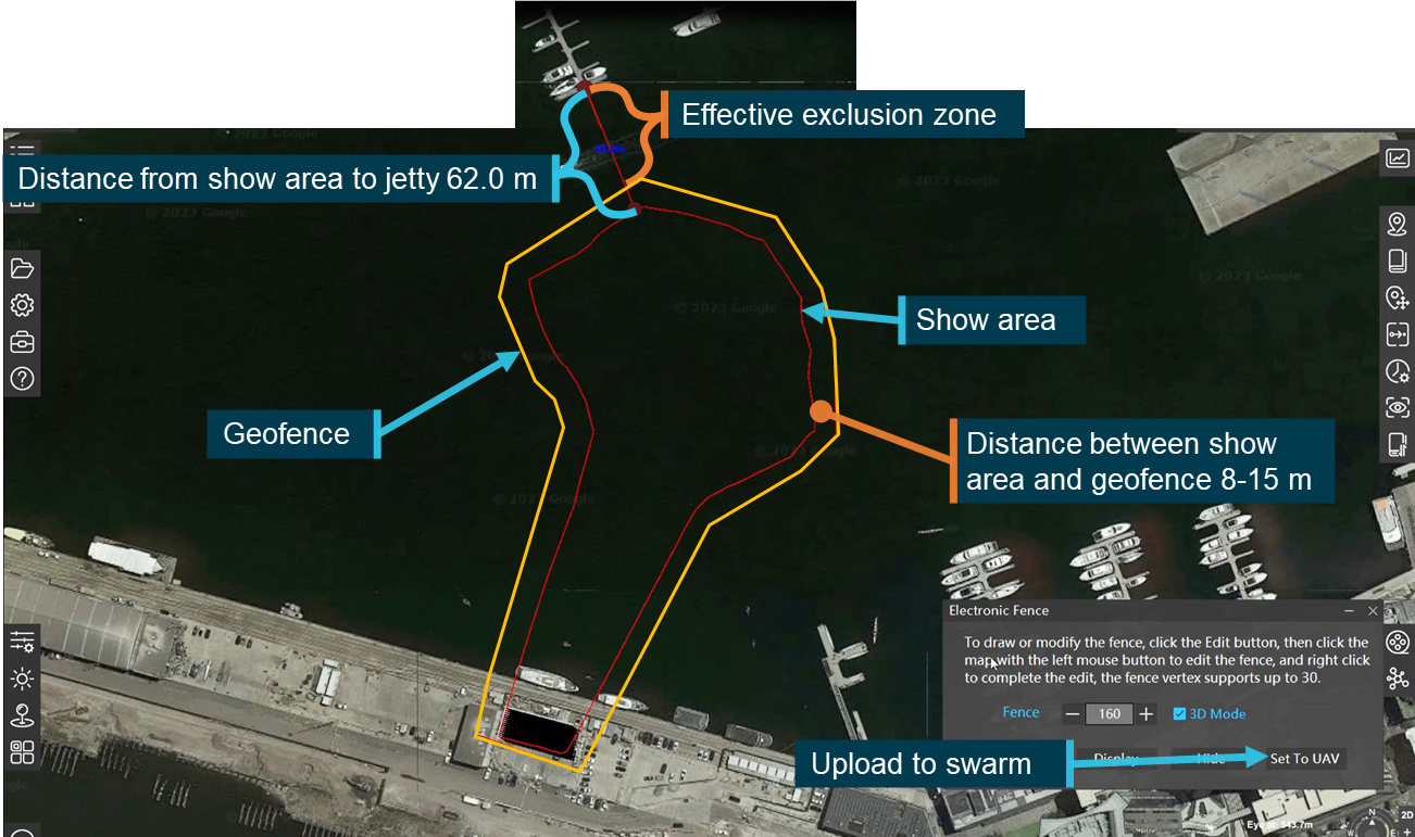
Source: Operator, modified and annotated by the ATSB
Based on the operator’s exclusion zone calculation process, the ATSB assessed the size of zone required to contain aircraft operating at maximum show speed and subject to a tailwind of twice the approved limit of the aircraft (16 m/s) at a height of 126 m (the maximum planned height of the show). In that scenario, an exclusion zone of more than 100 m would have been required.
Meteorological information
Operator accessed information
The flight crew advised that, throughout the afternoon and in the lead‑up to the show, they had accessed meteorological information from several sources. This included the Bureau of Meteorology (BoM), Windy and Willy Weather applications and aviation meteorological forecasts, including the relevant graphical area forecast and terminal area forecast for Essendon Airport (6 nautical miles to the north-west of Docklands). In discussing the wind conditions the flight crew noted that they were above the limit of the aircraft, but expected them to ease leading up to the show time.
Ground‑based monitoring
The flight crew were monitoring the wind speed on the ground using a handheld anemometer[6]. The flight crew reported that during the set‑up for the show the wind had been recorded in excess of the aircrafts’ limit.
Table 2 shows the recorded wind readings that were taken in the 40 minutes leading up to the show, ending at 1817.
Table 2: Wind speed measurements taken at launch site recorded by GCS
| Local time | Wind Speed (knots) | Wind Speed (m/s) | Notes |
| 1750 | 14 | 7 | |
| 1752 | 11 | 5.5 | |
| 1754 | 12 | 6 | |
| 1754 | 29 | 15 | Crew member recorded advising ‘only for a second but then it went back down to 12’ |
| 1817 | 14 | 7 | |
| 1830 | - | - | Show launch |
| Aircraft wind limit | 16 | 8 |
Bureau of Meteorology aviation forecasts and observations
The graphical area forecast issued by the BoM, valid at the time of the show for the Docklands area, identified surface visibility exceeding 10 km and severe turbulence below 6,000 ft for most of south‑eastern Victoria.
At 0927 on the day of the show the BoM issued a terminal area forecast (TAF) for Essendon Airport (YMEN)[7]. The TAF was valid between 1000 and 2200 local time on the day of the show. It forecast winds from the north at 18 kt gusting to 28 kt, strengthening to 20 kt gusting 32 kt from 1100, with severe turbulence below 5,000 ft from 1000.
At 1507 the BoM issued an amended TAF valid from 1600 till 0400 the day after the show. From 1600 it forecast winds from the north at 18 kt gusting 28 kt and severe turbulence below 5000 ft. From 2200 winds were forecast from the north at 14 kt with the turbulence reducing to moderate.
Corresponding observations
METAR and SPECI information for YMEN for the period from the start of the amended TAF at 1600 until 1830 (the show launch time) was consistent with the forecast conditions. The wind direction was consistently from the north and wind speeds varied around the aircrafts’ limit, with gusts between 25–30 kt (Figure 15).
Figure 15: YMEN wind speed observations
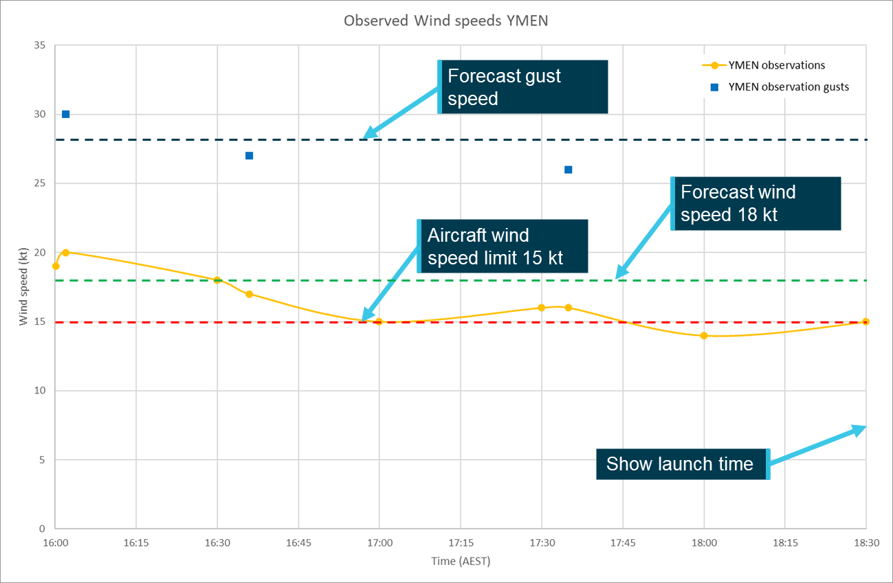
Source: ATSB using BOM data
Aircraft
While airborne and connected to the GCS the aircraft reported wind speed and direction information, which was displayed on the wind monitor. The wind speed was manually extracted from the GCS recording and plotted at 5 second intervals showing the changes in wind speed throughout the occurrence (Figure 16).
Within 10 seconds of the first data being recorded, the aircraft were operating in excess of the wind speed limit. As the aircraft climbed during the transition to the show area the wind speed increased rapidly progressing to more than double the 8 m/s limit of the aircraft.
Over the following 35 seconds the wind speed decreased and remained at or close to the limit until 1833:30, approximately 2 minutes after the show was launched. At the time the wind speed decreased most of the aircraft had activated their failsafe mode and were attempting to land in the water. Notwithstanding the potential effect of wind gusts, at these lower heights the wind speeds were likely closer to the speeds recorded on the ground before launch.
Figure 16: Wind speeds displayed on the GCS
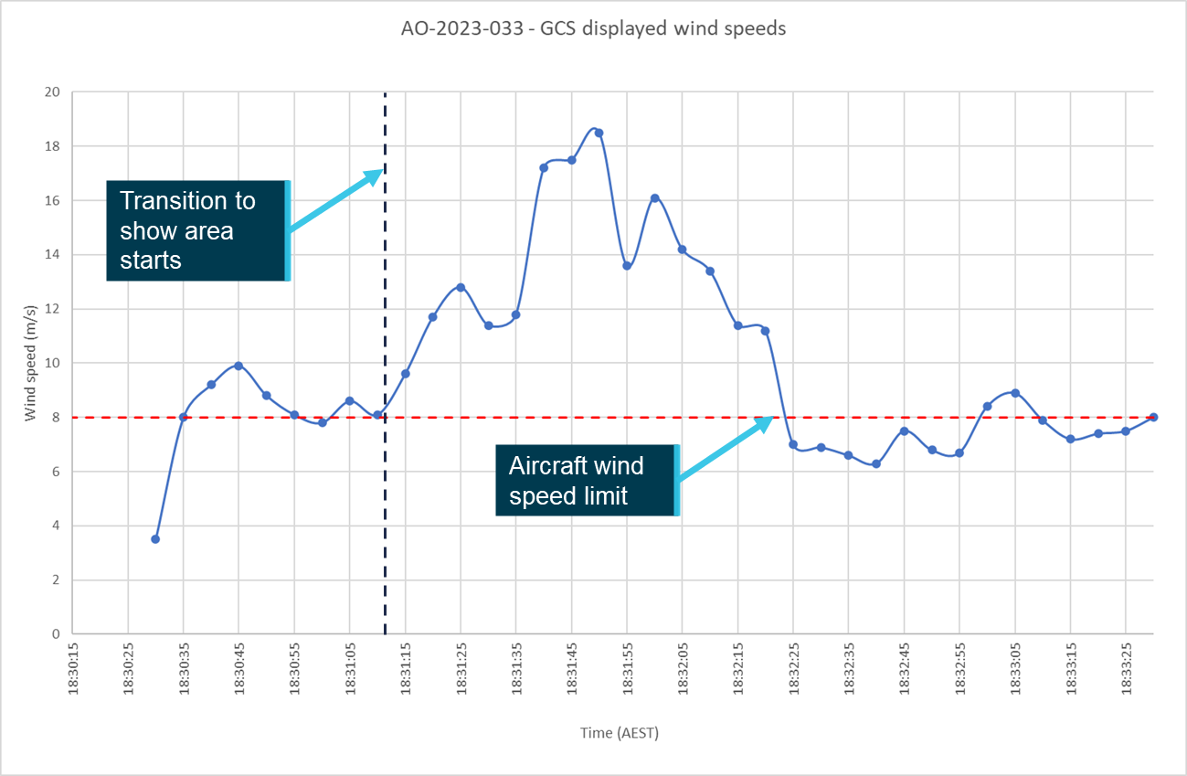
Source: ATSB based on operator data
Recorded data
Aircraft
Following the occurrence the operator downloaded the flight logs from the aircraft that were not submerged and provided these, along with the screen recording and logs from the GCS software to the manufacturer for further analysis.
The manufacturer identified that up to 397 aircraft simultaneously reported ‘T’ errors. Further analysis of the available logs indicated that aircraft throttled to 100% and that the recorded pitch angle of the aircraft (max 53°) exceeded the normal flight angle (Figure 17).
The manufacturer concluded that the aircraft had encountered wind conditions exceeding their capability.
Figure 17: Aircraft pitch, roll and throttle parameters
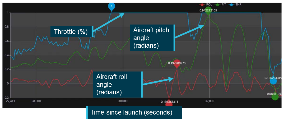
Source: Manufacturer, annotated by the ATSB
Specifically, while most of the aircraft were showing the commanded loiter mode, the manufacturer identified that:
Due to the influence of the wind speed, the power of the motors was no longer able to provide the required lift for the drones, so they moved up and down and slowly landed.
Without the capacity to provide the required lift the aircraft could not maintain position in the loiter as the RPIC had commanded and subsequently descended. This resulted in most of the aircraft ditching into the harbour. The GCS recording did not show evidence of a mode change, with most aircraft still showing the ‘L’ indicating they were in loiter mode on the GCS when connection was lost.
The manufacturer’s report also stated that the pilot was responsible for testing the wind speed and should be aware that the winds at height may be greater than that on the ground.
Ground control station
In accordance with the operator’s show day checklist the RPIC started screen recording on the GCS laptop computer at 1740, 50 minutes before the show was launched. The recording captured all activity that was displayed on the screen, including command inputs and selections, errors and function displays through until 1920, 50 minutes after launch.
The recording only captures what was displayed on the screen and not the information that the software used to generate the visual display. For example, during the show an aircraft status window was open over the location map so the location of the aircraft during and after transition into the show area was not visible.
The software used to record the screen also recorded the input from the computer’s microphone, capturing the interactions and communications between various crew members that were within range. Appendix A summarises the recording leading up to the show.
Closed circuit television
A series of 6 closed circuit television (CCTV) cameras around Victoria Harbour (Figure 18) captured the show’s launch, transition to the show area and some of the show. The footage captured the uncommanded movement of multiple aircraft, aircraft collisions, the aircraft landing in the water and the fly away aircraft (Figure 2).
Camera 1 captured the location of the boat mast that the RPIC had identified as presenting an obstacle to the swarm (Figure 2). Camera 4 captured multiple flags showing full extension at the time that the show was launching in the background. Noting that wind conditions varied with height, this camera was used to gain a general understanding of the conditions around the show site in the lead‑up to, and at the time of, the show.
Figure 18: CCTV cameras around Docklands
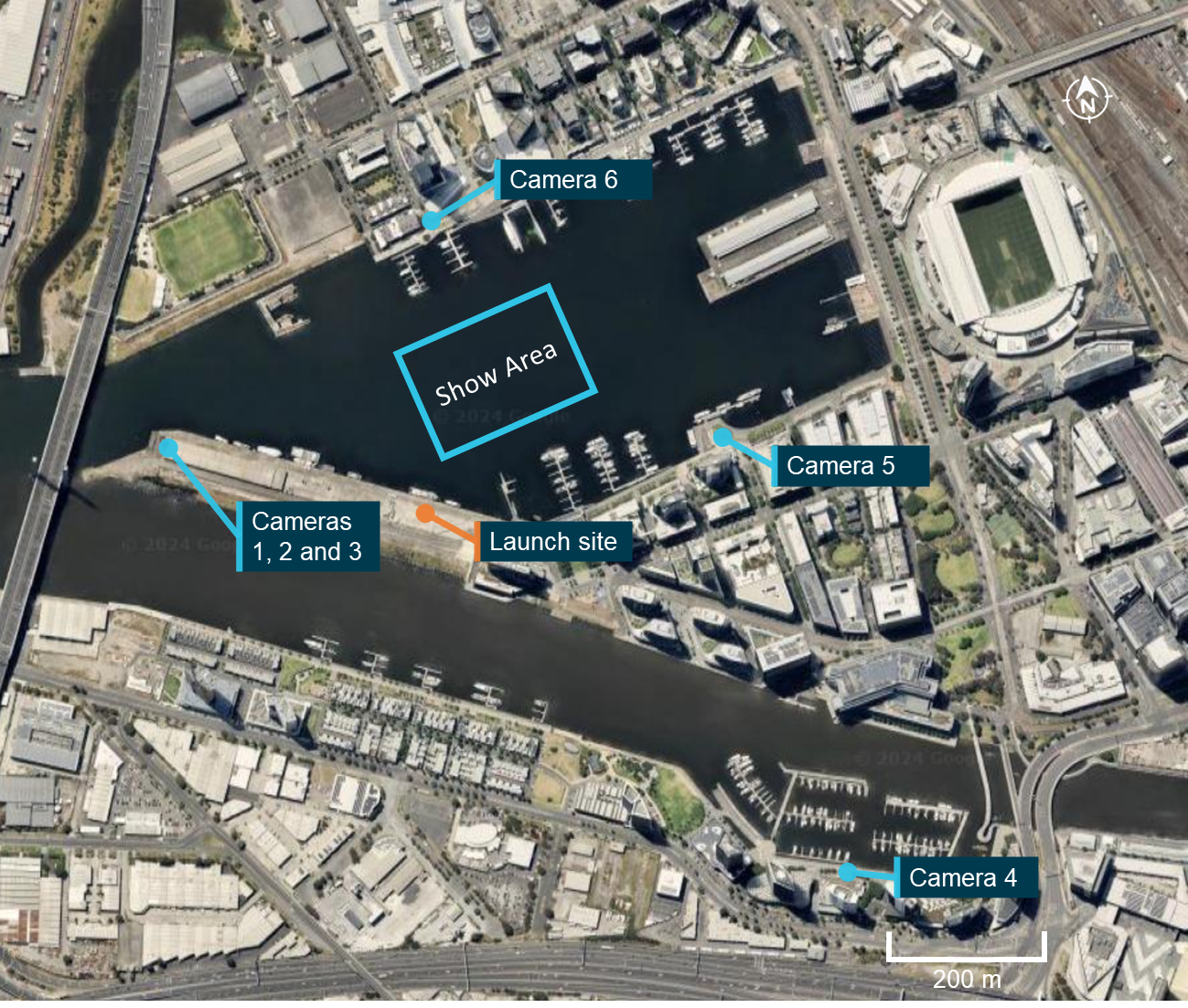
Source: Google Earth, annotated by the ATSB
Safety analysis
Introduction
At 1830 on 14 July 2023, the remote pilot in command (RPIC) of a swarm of 500 Damoda Newton V2.2 aircraft commanded the aircraft to launch to conduct a light show. Shortly after launch, and before the aircraft transitioned to the show area, the RPIC was presented with an increasing number of errors. The swarm continued towards the show area where further errors presented with multiple aircraft entering failsafe modes and landing or falling into the water. A total of 427 aircraft were submerged, with only 236 recovered.
The following analysis will consider the conduct of the show from the launch to the aircraft ditching into the water, including the factors that impacted the decision to launch. It will also review several safety issues that increased the risk to the operation.
Launch decision
Available information
Prior to the show the flight crew monitored wind conditions by referencing various weather sources and taking wind speed measurements at ground level. The conditions on the ground were below the limit of the aircraft with gusts exceeding the limit. The flight crew expected that, based on their interpretation of the available forecasts, wind conditions would ease in the lead‑up to the show time.
However, at 1817, 13 minutes before the show launch, a wind speed of 7 m/s was recorded on the ground, only 1 m/s below the allowable wind limit. At this time there was a conversation between the RPIC and the copilot about the wind conditions. The RPIC identified that the conditions on the ground were near the limit of the aircraft and that the wind speed in the show area was likely to be higher than that at ground level. The copilot responds that it’s only gusting and that they just have to get off the ground. In the following 13 minutes prior to the launch the RPIC was occupied with other tasks and no further wind speed assessment was undertaken.
Contributing factor The remote pilot in command launched the show with the wind speed close to the limit of the aircraft and aware that conditions in the show area were likely to be worse than those on the ground. |
Wind management plan
The version of the operator’s wind management plan current at the time of the accident provided guidance for the collection of wind information within the show area using a weather drone. The RPIC was aware of the wind management plan but not that it contained the option to use a weather drone. That understanding was consistent with the content of the previous version of the plan that did not contain that option.
As the wind management plan was attached to the event operational plan, which was prepared by the RPIC and approved by the copilot in their role as CRP, both flight crew should have been aware of the plan’s availability to them on the night of the show and its contents. However, in response to the draft report, both advised that they were unaware of its attachment to the event operational plan. Further, as the wind management plan had not been included in any operational process or procedure there was no prompt for the flight crew to review or access the plan prior to the show for guidance in the windy conditions. Subsequently, neither the plan nor the weather drone option it contained were used.
If a weather drone had been launched it is highly likely that it would have encountered conditions like those experienced by the swarm. That would then have provided the flight crew with confirmation that conditions were unsuitable for the light show to proceed.
Contributing factor In the lead‑up to the show, the flight crew did not use a weather drone to conduct a wind check at show altitude as outlined in the operator's wind management plan. As a result, the remote pilot in command did not have accurate information about the conditions within the show area at the time they launched the swarm. |
Control issues and ditching
Show launch
Ten seconds after the RPIC commanded the swarm to launch, the wind speed displayed on the ground control station (GCS) was equal to the aircrafts’ limit of 8 m/s. A further 10 seconds later the readout was showing a wind speed of 9.9 m/s. At this time 85 aircraft were displaying errors on the GCS. Of these, the 20 where the error type was visible were all showing ‘T’ errors indicating that they were out of position. The manufacturer’s analysis of the flight data identified that these ‘T’ errors were presented due to the aircraft motors being unable to hold position against the prevailing wind.
Having ruled out interference with or spoofing of the GNSS signal the ATSB also considered the possibility of a malicious actor attempting to take control of the swarm. However, the GCS computer showed no unexpected changes to aircraft mode or any commands received by the aircraft that were not commanded either by the RPIC or automatically through aircraft logic. Additionally, if the aircraft had been interfered with and tasked to alternate positions then they would likely not have recorded out of position errors.
Contributing factor Shortly after launch, before transitioning to the show area, the swarm encountered wind conditions that exceeded the aircrafts’ operational manoeuvring capability. This resulted in multiple aircraft being out of position and errors presenting on the ground control station computer. |
Ground control station wind speed display
There was no indication from the discussion, comments or actions recorded on the GCS computer that the flight crew identified a wind limit exceedance. They did not equate the 85 aircraft indicating ‘T’ errors to a limit exceedance or identify the wind speed readout. The RPIC and copilot were both unaware of the GCS wind speed display functionality so were not monitoring it for limit exceedances. They stated that if they had identified that the wind was in exceedance of limit that they would have taken actions to terminate the show.
Once the show had launched the copilot’s responsibilities as outlined in the operations manual were to monitor the airspace for relevant traffic, visually observe the swarm and to monitor it for fly aways. These 3 tasks required the copilot’s attention to be on the swarm and the surrounding airspace rather than detail displayed on the GCS computer. While the copilot visually identified aircraft out of position, they did not associate it with a wind speed limit exceedance.
Contributing factor The flight crew were both unaware that the ground control station had a wind speed monitoring function. The remote pilot in command did not use it to monitor the wind conditions after take-off. As a result, they did not identify that the wind exceeded the aircrafts’ limits and continued with the transition to the show area. |
Movement into the show area
As the aircraft moved into the show area along the pre‑programmed flight paths, the wind speed increases noticeably from 8.3 m/s to 18.5 m/s 40 seconds later. CCTV footage showed multiple aircraft in the upper layers of the show drop into the lower layers and collide with one another. The GCS displayed an increasing number of errors across all 3 categories. Not all errors were shown on the screen simultaneously so it was not possible to determine the exact number of aircraft presenting each error. However, the manufacturer’s analysis showed a maximum of 397 aircraft simultaneously recorded T errors indicating that they were out of position and the GCS recorded at least 11 aircraft presented with F errors indicating that they had breached the geofence.
The RPIC’s last command to the swarm was to loiter, the manufacturer’s analysis confirmed that this command was received by aircraft in the swarm. The manufacturer’s analysis further identified that, due to the wind conditions the motors were unable to provide the required lift to remain airborne while attempting to maintain their position. The manufacturer reported that they subsequently descended into the water below their location.
Contributing factor Shortly after starting the transition into the show area, the swarm encountered wind conditions that were more than double the published capability of the aircraft. This led to multiple aircraft being unable to hold position, with at least 11 aircraft breaching the geofence, multiple aircraft collisions and most aircraft descending into the water. |
Human Factors
Pilot workload
All tasks require a level of cognitive load to process the information and undertake the activity. Workload is a measure of the amount of mental effort that is needed or expended to process this information. Humans have a limited capacity to process information, where the information processing required is close to, or exceeds, the human capability this is referred to as overload and can have multiple negative effects on performance. These effects can include, task shedding, attentional focusing, reduction in situational awareness, increased fatigue and the increased chance of errors. (United Kingdom Civil Aviation Authority, 2016)
The level of workload that an individual task requires varies depending on a range of factors. These include the difficulty of the task, familiarity and recency with the task, the number of other tasks that are being conducted concurrently and the time available to complete the task. (United Kingdom Civil Aviation Authority, 2016)
The completion of an RPAS light show requires flight crew to be familiar and interact with multiple systems including:
- the aircraft
- the various hardware and software elements of the GCS
- condition monitoring equipment
- operational processes and procedures.
The flight crew also need to interact with and manage support crew and stakeholders. The operator had procedures to mitigate this through the implementation of the multi‑crew operation requiring at least 2 flight crew members for shows of more than 10 aircraft.
Workload review
A review of the operational environment in the lead‑up to and at the time the show was launched identified 2 factors that increased the RPIC’s workload above the normal level for show operations. These were the
- copilot’s limited experience in show operations
- RPIC’s lack of familiarity with adjusting the show position.
Copilot experience
For this operation the operator’s chief remote pilot (CRP) was performing the role of copilot. At the time of the show the RPIC had completed almost twice as many shows as the copilot, and the copilot had only conducted a single show in the previous 6 months, which was on the Wednesday night before this show. While not required to be, the copilot was also not approved by CASA to operate in the RPIC role.
At interview both flight crew identified that the copilot had less experience in show operations compared to the RPIC and the copilot themselves identified that, while current, they were ‘rusty’ when it came to show processes and procedures. As a result, some tasks that were normally assigned to the copilot were carried out by the RPIC. The GCS recording captured the RPIC:
- actively managing various stakeholders and the show support crew
- ensuring that the show timings were met
- alerting the copilot of an aircraft fly away.
All these tasks were the responsibility of the copilot in the operator’s procedures. The RPIC reported that if they had been operating with a more current pilot the division of tasks would have been more equal, which would have reduced their mental load.
The increased tasks that the RPIC carried out meant that they had to move from task to task rapidly, and work on multiple tasks concurrently. Both of which are known to increase workload. (United Kingdom Civil Aviation Authority, 2016)
RPIC lack of familiarity
On the night of the show the presence of the boat mast hazard meant that the RPIC had to reposition the show. Being unfamiliar with the required process, the RPIC elected to consult, by phone, with another pilot who was familiar with the system.
The conversation between the RPIC and the other pilot had been prearranged for 1800, 30 minutes before the show launch time. However, the other pilot did not call back until 8 minutes later, leaving only 22 minutes before launch to effect the change.
Subsequently the RPIC was preoccupied with tasks of moving the show for 18 of the 30 minutes leading up to the show. Based on the required actions it was assessed that, for someone familiar with the process and site, the move of the show could have been completed in about 5 minutes.
In summary, the combination of task unfamiliarity, time pressure and extra tasks due to the copilot’s limited show experience significantly increased the RPIC’s workload in the lead‑up to launch. That reduced the effectiveness of the wind speed assessment vital for the safety of the launch decision.
Contributing factor The remote pilot in command's workload was significantly increased due to their unfamiliarity with the process to make the necessary show position adjustment and the copilot’s limited knowledge and experience in show operations. This reduced the effectiveness of the wind speed assessment vital for the safety of the launch decision. |
Operational pressure
Pressure refers to a feeling of internal or external stress, which may not necessarily be based on actual urgency or necessity. This pressure can stem from various sources, such as tight schedules, stakeholder expectations or personal standards of performance. It can lead to rushed decisions, cutting corners or taking of unnecessary risks that can impact the safety of operations. (Ramdeen, 2024)
Multiple ATSB investigations and other publications have discussed the impact that personal, social or organisational pressures (perceived or actual) can have on pilot weather‑related decision‑making. In their safety leaflet about visual flight rules into instrument meteorological conditions (VFR into IMC) occurrences, (UK CAA, 2024) the United Kingdom Civil Aviation Authority (CAA) identified that as a pilot:
‘You may feel pressure to commence or continue a flight due to factors such as time constraints, passenger expectations, disruption to your personal life or the continuation bias of wanting to execute the intended plan. The effect of these pressures is sometimes referred to as ‘get-there-itis’ and can lead to a disregard for weather conditions or an overly optimistic interpretation of the situation, increasing the likelihood of a VFR into IMC scenario’
As a large public event an RPAS light show will likely place a level of pressure on the flight crew, and particularly the RPIC, for the show to go ahead. The operator’s procedures went some way to mitigating this hazard by assigning the copilot the task of stakeholder engagement to isolate the RPIC from the potential pressures. On this occasion however, the RPIC conducted this task.
Factors known to increase pressure
A review of the operational environment on the night of the show identified a number of the factors that the CAA identified as likely to increase pressure. These, together with 2 other factors, are discussed in the following sections.
Time constraints
To conduct the show, the harbour needed to be closed to keep vessel traffic out of the exclusion area. To minimise disruption the port authority provided a 15‑minute time window, starting at 1830, for the 10‑minute show. In the days leading up to the show the operator identified that the forecast conditions at the show time were going to be marginal and had requested that the show time be moved later. The operator advised that the port authority would not allow them to move the show later due to the impact on the harbour’s operations. This meant that the RPIC had to launch at 1830, or the show could not go ahead.
Stakeholder expectation
RPAS light show operations do not involve passengers however there are other stakeholders who will have the same desire for a flight to go ahead and limited understanding of the operational requirements. In this case the client had expended significant capital and expected that the show would proceed.
The RPIC advised that they had been in contact with the client’s representative on multiple occasions in the lead‑up to the show giving updates on conditions and what that meant for the likelihood of the show going ahead. The RPIC stated that they were aware that the client had other people waiting on the decision as to whether the show would proceed.
Secondly, the recently appointed CEO and COO had limited experience with the light show operation and had travelled specifically to see this show and observe the operation in person. The RPIC advised that the CEO and COO had spoken with them in the lead‑up to the show and expressed a desire to see the show operate effectively.
Continuation bias
Continuation bias is ‘an unconscious cognitive bias to continue with the original plan in spite of changing conditions.’ (Transportation Safety Board of Canada, 2019) In a crewed operation continuation bias might appear as a pilot departing into questionable conditions on a route they have completed successfully a number of times before. It could also appear as a flight crew conducting multiple attempts to land at the destination airport rather than divert to a location where the conditions are more suitable. (Federal Aviation Administration, 2022)
The RPIC reported that the operator had never had to cancel a show due to wind conditions. Further, the RPIC’s records indicated that they had conducted more than 30 shows without incident. Therefore, continuing with the show launch was a familiar process and based on previous experience a negative outcome from this decision was not expected.
Additional factors
The light show was being conducted in a populated area, had been advertised by the client and was supporting a national sporting team’s fixture, which was expected to draw a large crowd. The show therefore had a higher than normal profile that provided significant publicity and an opportunity to demonstrate the operator’s capability.
On the night of the accident the copilot, as the operator’s CRP, held greater organisational authority than the RPIC. Despite the RPIC holding overall responsibility for the safe conduct of the flight, that pairing created a negative cockpit gradient. On multiple occasions during the lead‑up to the launch the copilot stated to the RPIC that they believed that the conditions are suitable for launch. While the RPIC identified that they were the ultimate authority onsite, the statements from the copilot potentially influenced their decision‑making.
Summary
The review of the operational environment identified that the RPIC was likely experiencing time pressure, expectations from the client and senior staff that the show would go ahead, an expectation bias as they had conducted many shows without a similar issue with these aircraft. As identified by the CAA these pressures can lead to a disregard or overly optimistic interpretation of the situation. Further increasing pressure the show had a higher than normal profile and there was a negative cockpit gradient between the RPIC and copilot.
The operator’s report into the accident identified that the RPIC had been placed under additional pressure by external factors including:
- the client engagement
- the time pressure from the time window available for the show to be carried out
- confidence in the fleet due to the number of successful shows that had been completed.
Further, the RPIC identified directly that they had felt that there was pressure to have the show happen and for it to be successful.
Leading up to the show the RPIC had information that the weather conditions on the ground were near, but below, the limit of the aircraft but the conditions within the show area were unknown. An optimistic interpretation of conditions in the show area would be that the conditions were better or at least equivalent to those at ground level. Under this interpretation of the conditions they would have been acceptable for the show to go ahead.
In crewed operations a poor weather‑related decision can put the aircraft, crew and passengers at risk of a fatal outcome. In uncrewed operations the primary risks relate to financial and reputational damage in the event of an incident or accident. While present, the risk to personal safety of the crew was low, which may have altered the flight crew’s risk perception or tolerance.
Contributing factor It is likely that the remote pilot in command perceived a higher than normal level of pressure for the show to go ahead. This combined with a higher than normal workload, contributed to their decision to launch the show into unknown wind conditions. |
Operational requirements
To mitigate against the boat mast obstacle the RPIC elected to lift the entire show by 8 m above the originally planned maximum height of 118 m to a height of 126 m. The operator’s CASA permission required the RPIC to comply with their approved operations manual and subsequently operations library. The operations library stated that shows were not to be conducted at night above 120 m (400 ft) unless a specific approval had been approved by CASA, no such permission had been issued for this operation.
At the time that they changed the show height the RPIC identified that they were in exceedance of the 400 ft limit. The phone discussion with the other pilot who was assisting in the show move identified that this was a minor breach of the limit, and it was mitigated by the presence of buildings that exceeded the maximum show height.
The CASA permission also required that the operations be conducted within an exclusion zone, which was detailed in the operations library. The role of the exclusion zone was to ensure that in the event of an aircraft loss of control, bystanders were maintained at a safe distance. For a maximum show height of 400 ft a minimum exclusion zone of 70 m was required. The exclusion zone set by the RPIC was not able to be precisely determined but was estimated to be between 47 and 54 m, from a publicly accessible jetty.
The exclusion zone is calculated based on aircraft height and wind conditions. The RPIC’s decision to lift the show to avoid the boat mast meant that the planned exclusion zone of 70 m was no longer applicable. The zone should have been recalculated based on the new show height. For an 8 m (26 ft) increase in show height the exclusion zone should have been increased by about 4 m. Further, the wind speeds that the aircraft encountered, being more than twice the wind limit, increased the required exclusion zone to more than 100 m.
The available data did not identify the maximum height that aircraft reached or whether any aircraft exceeded the exclusion zone. However, as the flight was automated, if it had continued as planned it would have been in breach of both the maximum height and exclusion zone restrictions approved by the regulator. By not complying with these limitations safety defences built into the documentation and approval process were removed. While this did not contribute to the accident, it increased the risk of an adverse outcome.
Other factor that increased risk The remote pilot in command programmed and launched the show with a maximum height which exceeded the 120 m limit and with an insufficient exclusion zone, both of which were limitations in accordance with the operator's CASA‑issued permission to conduct the shows. This increased the risk of injury to bystanders in the event of an aircraft malfunction. |
Ground control station capability
Version 3 of the Damoda flight control software introduced a wind speed read out, showing wind speed and direction, in the top right corner of the display. Following launch, if the wind speed limit was exceeded, no active alert was shown on the GCS computer display. In its report, the manufacturer expressed a view that the flight crew should be actively monitoring the wind speed readout.
An alert, visual, audible or tactile, improves the chance that the operator will be made aware of this information, especially when under high workload. In crewed aviation there are multiple alerts that are provided to pilots despite information already being presented independently to them. For example, aircraft are required to have an airspeed indicator but active stall warnings are commonly used.
The software displayed multiple types of alerts, which varied from individual aircraft showing single or multiple errors, through to pop‑up boxes advising that a command had failed to reach one or more aircraft. All were clearly identifiable on the screen and were easily interpreted by someone who was familiar with the system.
For light show operations wind speed and direction are critical to the safety of flight. The small tolerances between aircraft and their relatively light weight means that changes in wind speed can significantly impact the aircraft position and lead to an increased risk of collisions.
The implementation of an active alert to the wind speed monitoring function would improve the pilot’s ability to both identify and respond to wind speed exceedances.
The RPIC stated that they were not aware of the wind speed readout at the time of the occurrence. Therefore, for an alert to have been effective in this instance it would have had to both identify the wind speed readout and the exceedance to the flight crew. As the alerting function did not exist, it was not possible to determine if it could have effectively done both these things. As such, the lack of an alert was not considered contributory to the accident.
Other factor that increased risk Version 3 of the Damoda ground control station software included a wind speed readout, but did not actively alert the pilot if the wind speed limit was exceeded. This increased the risk that a pilot would fail to identify a limit exceedance and continue a show into unsafe conditions. (Safety issue) |
Pilot training
Following the introduction of version 3 of the GCS software, the operator’s pilots undertook familiarisation flights with the new software, and the manufacturer was consulted about issues when they were encountered. However, there was no formalised training, as there had been for an earlier version of the software, and there was no system of assessment in place to ensure that all pilots had an equivalent understanding of the software before they started using it operationally.
The operator had both initial training and proficiency requirements for pilots to ensure that they were competent in the systems that they would be expected to use. The ongoing proficiency checks were only required on the introduction of new aircraft types or annually or biennially, depending on how recently a pilot had completed operational flights. As such, if a pilot had recently been checked and a new software version was then introduced it could be up to 2 years of operational flying before their proficiency on the new software and understanding of all its features would be assessed.
The flight crew for this show were not aware of the wind speed indication function or confident in the process of moving the show. However, at least one other pilot was aware of these systems and how to effectively use them.
Without a timely verification process in place there was no way for the operator to know whether their familiarisation process had been effective and if the pilots understood how to use the relevant features in an operational environment. Had such a system been in place, it is more likely that the flight crew would have identified the wind speed limit exceedance and that moving the show would have been done more efficiently.
Other factor that increased risk The operator did not provide formal training on version 3 of the ground control station software to its pilots, instead relying on familiarisation flights and ad hoc advice from the manufacturer. This increased the risk that show-qualified pilots would fail to identify exceedances in flight critical parameters and experience increased workload. (Safety issue) |
Operational document changes
The option of using weather drones to assess airborne conditions was introduced with version 1.1 of the wind management plan, dated 6 June 2023. This represented a significant change in the information gathering process for the wind speed information in the lead‑up to the show. The wind management plan, along with the event risk assessment, the emergency management plan and the maritime safety management plan, were available to the flight crew as attachments to the event operational plan. While the event plan was available, it was not a primary reference during preparations for the show. The show day and pre‑flight checklists were the primary references.
As neither of these documents contained reference to either the weather drone or the wind management plan, subsequently the flight crew were less likely to use a weather drone to collect relevant information from the show area. That increased the risk of launching into unsafe flight conditions.
It could not be determined whether inclusion of the information in the operator’s procedures would have altered the outcome of the accident as it was not known how or where this information would have been included in the operational procedures/documents. Additionally, as not all the procedures such as the show day checklist were routinely used, the inclusion of the weather drone option may not have been identified by the members of the flight crew, particularly given the high workload and time‑restricted environment in the lead‑up to show launch.
Other factor that increased risk Following the introduction of a weather drone option to the wind management plan in June of 2023, the operator had not updated its operational procedures to include this option. As a result, flight crew were not prompted to use this method for gathering information on wind conditions in the show area prior to launch. (Safety issue) |
Findings
ATSB investigation report findings focus on safety factors (that is, events and conditions that increase risk). Safety factors include ‘contributing factors’ and ‘other factors that increased risk’ (that is, factors that did not meet the definition of a contributing factor for this occurrence but were still considered important to include in the report for the purpose of increasing awareness and enhancing safety). In addition ‘other findings’ may be included to provide important information about topics other than safety factors. Safety issues are highlighted in bold to emphasise their importance. A safety issue is a safety factor that (a) can reasonably be regarded as having the potential to adversely affect the safety of future operations, and (b) is a characteristic of an organisation or a system, rather than a characteristic of a specific individual, or characteristic of an operating environment at a specific point in time. These findings should not be read as apportioning blame or liability to any particular organisation or individual. |
From the evidence available, the following findings are made with respect to control issues and ditching involving RPA swarm of 500 Damoda Newton 2.2 RPA, Victoria Harbour, Docklands, Victoria on 14 July 2023.
Contributing factors
- The remote pilot in command launched the show with the wind speed close to the limit of the aircraft and aware that conditions in the show area were likely to be worse than those on the ground.
- In the lead‑up to the show, the flight crew did not use a weather drone to conduct a wind check at show altitude as outlined in the operator's wind management plan. As a result, the remote pilot in command did not have accurate information about the conditions within the show area at the time they launched the swarm.
- Shortly after launch, before transitioning to the show area, the swarm encountered wind conditions that exceeded the aircrafts’ operational manoeuvring capability. This resulted in multiple aircraft being out of position and errors presenting on the ground control station computer.
- The flight crew were both unaware that the ground control station had a wind speed monitoring function. The remote pilot in command did not use it to monitor the wind conditions after take-off. As a result, they did not identify that the wind exceeded the aircrafts’ limits and continued with the transition to the show area.
- Shortly after starting the transition into the show area, the swarm encountered wind conditions that were more than double the published capability of the aircraft. This led to multiple aircraft being unable to hold position, with at least 11 aircraft breaching the geofence, multiple aircraft collisions and most aircraft descending into the water.
- The remote pilot in command's workload was significantly increased due to their unfamiliarity with the process to make the necessary show position adjustment and the copilot’s limited knowledge and experience in show operations. This reduced the effectiveness of the wind speed assessment vital for the safety of the launch decision.
- It is likely that the remote pilot in command perceived a higher than normal level of pressure for the show to go ahead. This combined with a higher than normal workload, contributed to their decision to launch the show into unknown wind conditions.
Other factors that increased risk
- The remote pilot in command programmed and launched the show with a maximum height which exceeded the 120 m limit and with an insufficient exclusion zone, both of which were limitations in accordance with the operator's CASA‑issued permission to conduct the shows. This increased the risk of injury to bystanders in the event of an aircraft malfunction.
- Version 3 of the Damoda ground control station software included a wind speed readout, but did not actively alert the pilot if the wind speed limit was exceeded. This increased the risk that a pilot would fail to identify a limit exceedance and continue a show into unsafe conditions. (Safety issue)
- The operator did not provide formal training on version 3 of the ground control station software to its pilots. Instead, relying on familiarisation flights and ad hoc advice from the manufacturer. This increased the risk that show-qualified pilots would fail to identify exceedances in flight critical parameters and experience increased workload. (Safety issue)
- Following the introduction of a weather drone option to the wind management plan in June of 2023, the operator had not updated its operational procedures to include this option. As a result, flight crew were not prompted to use this method for gathering information on wind conditions in the show area prior to launch. (Safety issue)
Safety issues and actions
Central to the ATSB’s investigation of transport safety matters is the early identification of safety issues. The ATSB expects relevant organisations will address all safety issues an investigation identifies. Depending on the level of risk of a safety issue, the extent of corrective action taken by the relevant organisation(s), or the desirability of directing a broad safety message to the Aviation industry, the ATSB may issue a formal safety recommendation or safety advisory notice as part of the final report. All of the directly involved parties were provided with a draft report and invited to provide submissions. As part of that process, each organisation was asked to communicate what safety actions, if any, they had carried out or were planning to carry out in relation to each safety issue relevant to their organisation. Descriptions of each safety issue, and any associated safety recommendations, are detailed below. Click the link to read the full safety issue description, including the issue status and any safety action/s taken. Safety issues and actions are updated on this website when safety issue owners provide further information concerning the implementation of safety action. |
No trigger in key operational documents to use weather drone
Safety issue number: AO-2023-033-SI-01
Safety issue description: Following the introduction of a weather drone option to the wind management plan in June of 2023, the operator had not updated its operational procedures to include this option. As a result, flight crew were not prompted to use this method for gathering information on wind conditions in the show area prior to launch.
Ground Control Station pilot assurance
Safety issue number: AO-2023-033-SI-02
Safety issue description: The operator did not provide formal training on version 3 of the ground control station software to its pilots. Instead, relying on familiarisation flights and ad hoc advice from the manufacturer. This increased the risk that show-qualified pilots would fail to identify exceedances in flight critical parameters and experience increased workload.
Safety recommendation to The Australian Traffic Network Pty Limited
| The ATSB makes a formal safety recommendation, either during or at the end of an investigation, based on the level of risk associated with a safety issue and the extent of corrective action already undertaken. Rather than being prescriptive about the form of corrective action to be taken, the recommendation focuses on the safety issue of concern. It is a matter for the responsible organisation to assess the costs and benefits of any particular method of addressing a safety issue. |
Safety recommendation number: AO-2023-033-SR-02
Safety recommendation description: The Australian Transport Safety Bureau recommends that The Australian Traffic Network Pty Limited develops a process to ensure that future software changes are communicated and understood by all pilots before commencing operations.
Aircraft control software
Safety issue number: AO-2023-033-SI-03
Safety issue description: Version 3 of the Damoda ground control station software included a wind speed readout, but did not actively alert the pilot if the wind speed limit was exceeded. This increased the risk that a pilot would fail to identify a limit exceedance and continue a show into unsafe conditions.
Safety recommendation to Damoda Intelligent Control Technology Co., Ltd
| The ATSB makes a formal safety recommendation, either during or at the end of an investigation, based on the level of risk associated with a safety issue and the extent of corrective action already undertaken. Rather than being prescriptive about the form of corrective action to be taken, the recommendation focuses on the safety issue of concern. It is a matter for the responsible organisation to assess the costs and benefits of any particular method of addressing a safety issue. |
Safety recommendation number: AO-2023-033-SR-01
Safety recommendation description: The Australian Transport Safety Bureau recommends that Damoda Intelligent Control Technology Co., Ltd implements active wind speed exceedance alerting in the ground control station software.
Safety action not associated with an identified safety issue
Additional safety action by The Australian Traffic Network Pty Limited
The Australian Traffic Network Pty Limited advised the ATSB that following this incident it implemented several changes to its show planning and conduct processes. These included:
- changes to the crewing requirements to have 2 CASA-approved pilots operating every show
- establishment of multiple go/no-go points during the launch sequence allowing for more clearly defined stop points
- introduction of sterile cockpit procedures to limit outside interactions with the flight crew in critical phases in the lead‑up to show launch.
Glossary
| ATN | The Australian Traffic Network Pty Limited |
| CAA | United Kingdom Civil Aviation Authority |
| CASA | Civil Aviation Safety Authority |
| CASR | Civil Aviation Safety Regulations |
| CCTV | Closed Circuit Television |
| CRP | Chief Remote Pilot |
| GCS | Ground Control Station |
| IMC | Instrument Meteorological Conditions |
| IP | Ingress Protection |
| JSA | Job Safety Assessment |
| LED | Light Emitting Diode |
| LiPo | Lithium Polymer |
| RePL | Remote Pilot License |
| RPA | Remotely Piloted Aircraft |
| RPAS | Remotely Piloted Aircraft System |
| RPIC | Remote Pilot in Command |
| RTK | Real Time Kinematic |
| RTL | Return To Launch |
| VFR | Visual Flight Rules |
Sources and submissions
Sources of information
The sources of information during the investigation included:
- the remote pilot in command and copilot
- The Australian Traffic Network Pty Limited
- the aircraft and ground control station software manufacturer
- Civil Aviation Safety Authority
- another Australian operator of the type
- ground control station software screen recording
- Bureau of Meteorology
- video footage of the accident flight and other photographs and videos taken on the day of the accident
References
Federal Aviation Administration. (2022). CFIT and Plan Continuation Bias. Washington DC: United States Department of Transportation.
Ramdeen, A. (2024, 04). Performing Under Percieved Pressure in Aviation Maintenance. Naval Safety Command Aviation Safety Blog.
SKYbrary. (2025, May). Authority Gradients. Retrieved from SKYbrary: https://skybrary.aero/articles/authority-gradients
Transportation Safety Board of Canada. (2019). AIR TRANSPORTATION SAFETY INVESTIGATION REPORT A18P0031 Loss of control and collision with terrain Island Express Air Inc. Beechcraft King Air B100, C-GIAE Abbottsford Airport, British Columbia 23 February 2018. Quebec: Transportation Safety Board of Canada.
UK CAA. (2024). VFR Flight Into IMC - CAP 2562. London: UK CAA.
United Kingdom Civil Aviation Authority. (2016). Flight crew human factors handbook. West Sussex: United Kingdom Civil Aviation Authority.
Submissions
Under section 26 of the Transport Safety Investigation Act 2003, the ATSB may provide a draft report, on a confidential basis, to any person whom the ATSB considers appropriate. That section allows a person receiving a draft report to make submissions to the ATSB about the draft report.
A draft of this report was provided to the following directly involved parties:
- remote pilot in command
- Australian Traffic Network Pty Ltd chief remote pilot
- Aircraft and GCS software manufacturer
- Civil Aviation Safety Authority
Submissions were received from:
- remote pilot in command
- Australian Traffic Network Pty Ltd chief remote pilot
The submissions were reviewed and, where considered appropriate, the text of the report was amended accordingly.
Appendices
Appendix A – Ground control station recording summary
| Time (local) | Speaker | Theme | Topic/ Quote |
| 1740 | Recording started | ||
| 1742-1743 | RPIC | Support crew management | RPIC demonstrated to crew members how to operate the radio and then directs what equipment they need to be taking with them. |
| 1747 | RPIC | Support crew management | RPIC directed support crew member what to be on the lookout for when monitoring airspace. |
| 1749 | Copilot | Flight crew interactions | Copilot noted that they have the Essendon Airport control tower VHF frequency ready if required. |
| 1750 | Support Crew member | Wind speed monitoring | Wind speed reading taken at 14 kt |
| 1752 | Support Crew member | Wind speed monitoring | Wind speed reading taken at 11 kt |
| RPIC | Support crew management | RPIC directed the support crew member to take a further wind speed reading on the grid. | |
| 1753 | RPIC and copilot | Stakeholder interactions | RPIC directed the copilot to conduct a radio check with the waterway authority boat |
| 1754 | Support Crew member | Wind speed monitoring | Wind speed reading taken 11.9 kt |
| Copilot | Wind speed monitoring | Copilot responds that ’that’s ok it’s the 14 that we are worried about’ | |
| RPIC | Wind speed monitoring | RPIC identified that they have had multiple 29 km/h gusts and the threshold of the aircraft is 24-25 km/h | |
| 1756 | RPIC | Client interactions | RPIC dictated text message identified that current wind is above limit but is in line with forecast which is predicting it to drop. Says that ‘we are still preparing for launch’ |
| 1757 | RPIC | Show adjustment | RPIC’s first reference to needing to move the show to avoid the mast. Needed to work out how to lift the show over it. |
| RPIC | Support crew management | RPIC instructs support crew member on their role to ensure that unauthorised personnel are not in the area. | |
| 1758 | RPIC and copilot | Show adjustment | Initial discussion between RPIC and copilot regarding moving the show. Copilot asked what will use less battery, RPIC identifies that isn’t there primary concern but that lifting the show will exceed the permitted show altitude. |
| 1759 | RPIC | Show adjustment | RPIC identified that this is not something they have done before and will need to call a third pilot who is not on site to assist. Makes call and no answer.
|
| 1801 | RPIC | Show adjustment | RPIC performed a show test and identifies issue with the separation of the aircraft as they come back towards the recovery location at the end of the show. |
| 1803 | Copilot | Support crew management | Copilot confirmed with RPIC what the call signs of the support crew are for radio traffic and where they are located. |
| 1805 | RPIC and Copilot | Show adjustment | RPIC identified to copilot that the exclusion zone is 60.5 m which is short of the requirements. |
| RPIC and copilot | Wind speed monitoring | RPIC asked the copilot for their thoughts on the wind situation. Copilot responded that the aircraft will be able to hand the gusts but would be more concerned if it was constant. | |
| 1806 | RPIC | Show adjustment | RPIC attempted to call third pilot again no answer, RPIC notably frustrated. |
| 1807-1816 | RPIC, copilot and third pilot | Show adjustment | Third pilot calls back RPIC they discuss how to effectively move the show to ensure that the boat mast is avoided. |
| 1810 | Wind speed monitoring | Microphone records audible wind noise. | |
| 1811 | RPIC | Wind speed monitoring | Microphone again records audible wind noise. RPIC stated that if a gust like that happens on take-off this will be an issue. |
| 1814 | RPIC and third pilot | Show adjustment | RPIC identified that with the adjustment the show will now traverse to 135 m, above the maximum permitted height. Third pilot assured RPIC that there are buildings around higher than that so it is fine. |
| 1816 | RPIC | Client interactions | RPIC noted that the client has asked them to make a decision at 1815. |
| 1817 | Copilot | Wind speed monitoring | Copilot stated that they believe the show is good to launch. |
| RPIC & CoPilot | Wind speed monitoring | RPIC responded questioning the conditions at the height of the show. Copilot responded that they only have to get the show off the ground and over the dock. | |
| RPIC | Client interactions | RPIC dictated voice to text transmission to client advising ‘at the moment we are good to go’ | |
| RPIC & waterway authority | Stakeholder interactions | Waterway authority contacted the RPIC via radio confirming the waterway closure at 1825 | |
| 1817 - 1829 | RPIC & CoPilot | Pre-flight checklist | RPIC and copilot worked through the pre-flight checklist. Including responses for emergencies including EKF and W errors which are RTL, fly manually or land in the river. |
| 1823 | RPIC & support crew member | Support crew management | Support crew member requested a radio check interrupting the pre-flight checklist. |
| RPIC & waterway authority | Stakeholder interactions | Waterway authority radio call stating that they are closing the river. | |
| 1824 | RPIC & support crew member | Support crew management | Support crew member contacted RPIC and copilot about exit point access for a bystander. |
| 1825 | RPIC & support crew members | Support crew management | RPIC contacted support crew members advising them to close the exclusion zone. |
| 1826 | RPIC & support crew members | Support crew management | Support crew member contacted the RPIC requesting access to the exclusion zone for client personnel wishing to observe the show. After some confusion about what they were trying to do RPIC confirmed via copilot that they can come through. |
| 1828 | RPIC & CoPilot | Pre-flight checklist | RPIC requested airband call as per checklist, copilot inquired as to whether it’s necessary. RPIC responded that it’s their call and copilot completes the call. |
| 1829 | RPIC & CoPilot | Pre-flight checklist | RPIC and copilot completed the checklist. Copilot read out the last item ‘question PIC confidence’ RPIC response ‘terrified’ |
| Copilot | Wind speed monitoring | Copilot identified that the wind has died off and they are ‘all good’. | |
| 1830 | RPIC commands show launch | ||
| 1830:36 | RPIC | Observations | RPIC identified toilet bowling |
| 1830:42 | Copilot | Observations | Copilot identified 50+ T errors |
| 1831:05 | RPIC | Observations | RPIC alerted those around them to the fact that they might have drones fall on them. |
| 1831:11 | Aircraft commence transition to the show area | ||
| 1831:33 | RPIC | Observations | RPIC identified aircraft at the top falling into one another. |
| 1831:36 | Copilot | Observation | Copilot stated to pause it and switch off the lights. |
| 1831:43 | RPIC | Actions | RPIC attempted to loiter all aircraft in the show. |
| 1831:46 | RPIC | Observations | RPIC identified the fly away |
| 1831:47 | RPIC | Observations | RPIC identified that they loiter command has failed. |
| 1831:48 | First EKF (autopilot failure) Error is displayed | ||
| 1832:10 | RPIC and Copilot | Actions | RPIC asked copilot if they have control over the fly away. Copilot confirmed they do. |
| 1832:15 | RPIC | Observations | RPIC identified that there are now 10 EKF errors displaying. |
| 1832:24 | RPIC and Copilot | Actions | RPIC again confirmed that the copilot has control over the fly away and then says ‘disarm, disarm, disarm’ |
| 1832:40 | RPIC and copilot | Observations | Copilot asked if the aircraft can be landed, RPIC stated that they are off line so they cannot be selected to send a command to. |
| 1832:56 | RPIC | Observations | RPIC stated that ‘all failed’ error has presented. |
| 1833:11 | RPIC | Observations | RPIC stated that status of most aircraft cannot be determined as they are off line. But they are attempting to RTL each aircraft that is still connected. |
| 1836:19 | RPIC | Observations | RPIC identified that the show has ended aircraft are continuing to come back. |
| 1836:38 | Copilot | Observations | Copilot identified that aircraft are still returning to the grid. |
| 1837:05 | RPIC and copilot | Actions | RPIC directed the copilot to point the access points controlling the network out towards the show area to attempt to reconnect with the aircraft still in the area. |
| 1839 | RPIC | Observations | RPIC identified 2 further aircraft are returning to the grid. |
| 1840 | All aircraft have returned or lost connection to the GCS | ||
| 1841 | RPIC & waterway authority | Stakeholder interactions | Waterway authority contacted the RPIC to confirm they are ok to open the river. RPIC confirmed. |
| 1842-1844 | RPIC & support crew members | Support crew management | Support crew members requested and are granted permission to open the road and RPIC requests that they all return to operations control. |
Purpose of safety investigationsThe objective of a safety investigation is to enhance transport safety. This is done through: identifying safety issues and facilitating safety action to address those issues providing information about occurrences and their associated safety factors to facilitate learning within the transport industry. It is not a function of the ATSB to apportion blame or provide a means for determining liability. At the same time, an investigation report must include factual material of sufficient weight to support the analysis and findings. At all times the ATSB endeavours to balance the use of material that could imply adverse comment with the need to properly explain what happened, and why, in a fair and unbiased manner. The ATSB does not investigate for the purpose of taking administrative, regulatory or criminal action. TerminologyAn explanation of terminology used in ATSB investigation reports is available here. This includes terms such as occurrence, contributing factor, other factor that increased risk, and safety issue. Publishing informationReleased in accordance with section 25 of the Transport Safety Investigation Act 2003 Published by: Australian Transport Safety Bureau © Commonwealth of Australia 2025 
Ownership of intellectual property rights in this publication Unless otherwise noted, copyright (and any other intellectual property rights, if any) in this report publication is owned by the Commonwealth of Australia. Creative Commons licence With the exception of the Commonwealth Coat of Arms, ATSB logo, and photos and graphics in which a third party holds copyright, this report is licensed under a Creative Commons Attribution 4.0 International licence. The CC BY 4.0 licence enables you to distribute, remix, adapt, and build upon our material in any medium or format, so long as attribution is given to the Australian Transport Safety Bureau. Copyright in material obtained from other agencies, private individuals or organisations, belongs to those agencies, individuals or organisations. Where you wish to use their material, you will need to contact them directly. |
[1] For a limited test a smaller set of 10 aircraft from the main fleet are used. They are used to test the system and location without the need for all 500 aircraft and the associated support crew.
[2] The exclusion zone around the show was a safety feature in case of an aircraft issue that ensured that spectators were not injured by falling aircraft. It was calculated based on the height and maximum speed of the aircraft performing the show.
[3] Disarming the aircraft switched off the aircraft’s motors.
[4] Ingress protection code is given by a sequence of 2 digits following the letters IP and indicates how well a device is protected against the ingress of dust and water. The first digit indicates the level of protection from solid particle ingress from 0 (no protection) to 6 (dust tight). The second digit indicates that level of protection against water ingress from 0 (no protection) to 9 (protected against high pressure water jets and immersion in water).
[5] The minimum exclusion zone was 30 m unless otherwise specifically approved by CASA.
[6] Device that measures wind speed.
[7] The terminal area forecast issued by the BOM is valid for areas within 5 NM of the aerodrome. Subsequently the forecast is not officially valid for the Victoria Harbour.
Occurrence summary
| Investigation number | AO-2023-033 |
|---|---|
| Occurrence date | 14/07/2023 |
| Location | Victoria Harbour, Docklands |
| State | Victoria |
| Report release date | 15/07/2025 |
| Report status | Final |
| Investigation level | Defined |
| Investigation type | Occurrence Investigation |
| Investigation status | Completed |
| Mode of transport | Aviation |
| Aviation occurrence category | Ditching, Loss of control |
| Occurrence class | Accident |
| Highest injury level | None |
Aircraft details
| Manufacturer | DAMODA |
|---|---|
| Model | Newton 2.2 |
| Aircraft operator | The Australian Traffic Network Pty Ltd |
| Sector | Remotely piloted aircraft |
| Operation type | Part 101 Unmanned aircraft and rockets |
| Departure point | Docklands, North Wharf Road, Victoria |
| Destination | Docklands, North Wharf Road, Victoria |
| Damage | Destroyed |