Loss of control

Loss of control in flight involving Leonardo Helicopters AW139, VH-YHF, near Adelaide River mouth, 38 km east-north-east of Darwin, Northern Territory, on 13 May 2018

Final report

Report release date: 16/04/2020

Safety summary

What happened

At 2000 Central Standard Time on 13 May 2018, the crew of a Leonardo Helicopters AW139, registered VH-YHF, departed Darwin, Northern Territory, to search for an active emergency position-indicating radio beacon (EPIRB). The crew flew under night visual flight rules with support of a night vision imaging system.

During an approach to a potential EPIRB target, smoke from nearby bushfires affected visibility and the helicopter developed an uncommanded high rate of descent. The Aircrew Officer, in the rear of the helicopter, called ‘Climb! Climb! Climb!’, and the pilot regained control with a rehearsed recovery drill. During the recovery procedure, the power demand exceeded airframe limitations. This exceedance went undetected, and the helicopter was flown on a second sortie that same evening.

What the ATSB found

The pilot entered instrument meteorological conditions during approach, and lost control of vertical speed. The helicopter descended to 31 ft above ground level during the event. Reversion to standard patter and practiced drills allowed the crew to recover the situation and avert an accident.

Two layers of protection available to the crew of the helicopter were not used. Flight instruments were not referred to in the incident approach, and a crewmember trained to support the pilot in monitoring the approach was required to be in the rear of the aircraft.

A main gearbox over-torque of 159.5 per cent occurred during the recovery. The crew could not determine the magnitude of the potential over-torque after the event. Subsequently the aircraft remained in service in a condition of uncertain airworthiness.

What has been done as a result

CareFlight has established three main controls aiming to prevent reoccurrence:

  • Stabilised Approach Criteria was written into standard operating procedures, requiring an immediate go-around if the aircraft leaves a prescribed range of approach parameters.
  • Controlled flight into terrain (CFIT) avoidance training was incorporated into the ground-based training syllabus.
  • Improved advice on use of auto hover functions was written into aircraft handling standard operating procedures. This included a requirement that the function was not to be engaged while the helicopter was descending.

Safety message

Pilots must be aware of the human factors hazards associated with loss of visual references. Pilots can protect themselves by maintaining the use of instrument scans in approaches at night, and making use of monitoring by trained and available crewmembers.

Flight planning should include assessment of the risk of a degraded visual environment. Operators should document their minimum acceptable levels of illumination and levels of tolerable risk. Where the risk exists, predetermined responses should be readily available.

Instrument flight rules (IFR) pilots in IFR-rated aircraft should prioritise use of inadvertent instrument meteorological conditions drills and pre-planned exit routes over recovery of visual meteorological conditions.

Flight crew and engineering teams should not rely solely on indicators, or absence of indicators, to determine airworthiness. If there is any reason to suspect exceedance of aircraft limits, operators should run diagnostics to determine the airworthiness of the aircraft beyond doubt.

People have a responsibility to aid their own rescue. Up-to-date registration of an EPRIB, and correct use of an EBIRB and other signalling equipment, simplifies a rescue of people in need. Australian Maritime Safety Authority guidelines exist to help people prepare for onshore and offshore remote area travel.


The occurrence

Incident flight

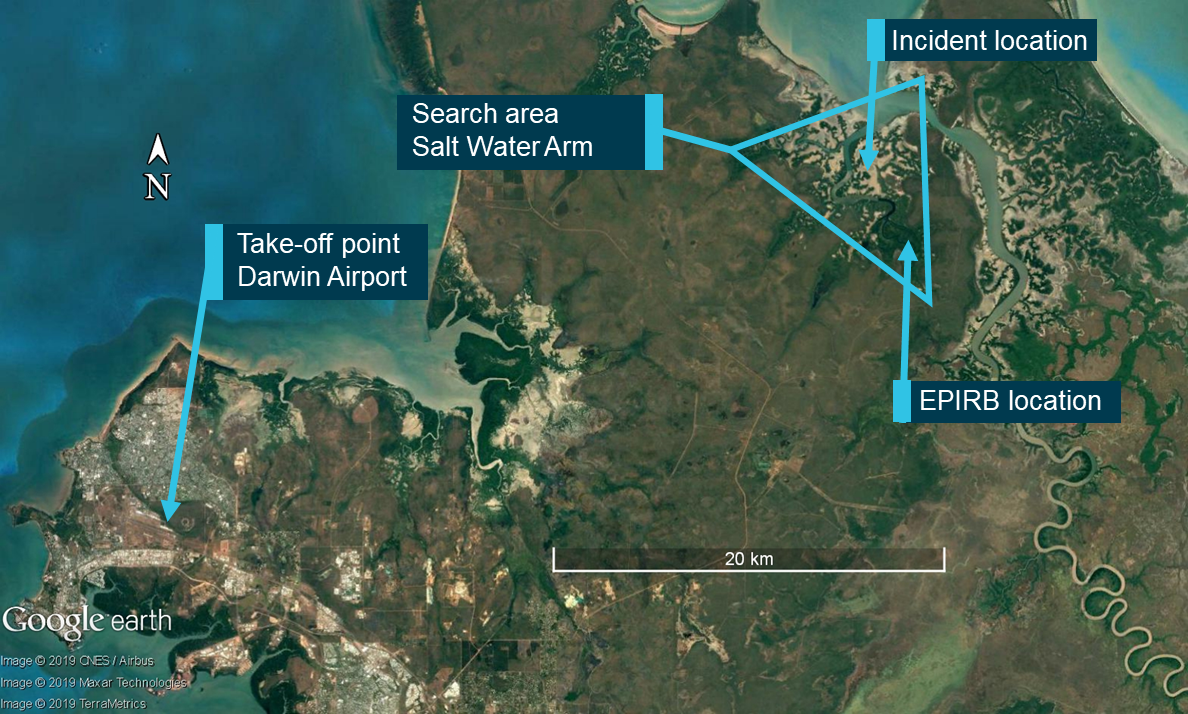
On the evening of 13 May 2018 at 1943 Central Standard Time,[1] the Rescue Coordination Centre (RCC) tasked the crew of a Leonardo Helicopters AW139, registered VH-YHF, to locate an active emergency position-indicating radio beacon[2] (EPIRB) 38 km north-east of Darwin Airport, Northern Territory. The EPIRB had been activated within the vicinity of a waterway called Salt Water Arm (Figure 1).

Figure 1: Map showing Darwin take-off point, search area, and location of incident event

Figure 1: Map showing Darwin take-off point, search area, and location of incident event. 
Source: Google Earth annotated by the ATSB

Source: Google Earth annotated by the ATSB

The area was popular with recreational anglers, so the crew of VH-YHF anticipated responding to a boating event. They also determined that such a response would likely require use of the aircraft’s winch.

The crew configured the aircraft with the pilot on night vision goggles[3] (NVG) in the front right seat, the aircrew officer (ACO) with NVG in the rear cabin by the right hand door, and the flight nurse in the rear cabin without NVG. Lighting within the cockpit and cabin was NVG-compatible. Two steerable searchlights mounted to the front, one steerable searchlight mounted to the right side of the aircraft, a handheld light operated by the ACO, and LED light bars at the front and rear of the helicopter supported the Night Vision Imaging System[4] (NVIS).

At about 2000, the crew departed Darwin Airport with good visibility. At that time, a five-metre tide was receding from Salt Water Arm. There was little illumination as the moon had set at 1653, and the sun had set at 1830. There was limited celestial light available through the gaps in the clouds which were forecast as scattered[5] cumulus and stratocumulus clouds at 2,000 ft, with cloud tops to 10,000 ft. Smoke from outlying grass fires drifted across the search area below 7,000 ft, reducing visibility to 4 km in places. The crew could not easily detect the smoke due to low illumination.

As the crew descended into the search area and commenced the search, smoke became evident as the task progressed. The ACO described visibility as 5 km but dropping in and out due to large amounts of smoke. These conditions are common for the region, and recent check flights for the crew had been conducted in similar conditions.

During the flight, the beam of the search light would reflect off smoke and ash. Backscatter from the beam was affecting visibility, reducing NVG image quality, and reducing peripheral vision. As a result, the beam required frequent adjustment. The ACO contacted the RCC and advised that limited visibility may hamper the operation.

The helicopter was fitted with direction-finding equipment (DF) which enabled the crew to locate the source of a 121.5 MHz beacon signal, such as the EPIRB. The crew found that readings from the DF were erratic and unreliable. This added a level of complexity to the operation, making it difficult to locate the beacon. As a result, the crew conducted a visual search for potential targets from a safe working height of above 800 ft above ground level (AGL).

While the use of NVG allowed the crew to detect targets, the image quality was not high enough to verify the targets from this safe working height. The crew had to fly the aircraft down to 400 ft AGL to verify whether their target was one requiring rescue. The crew flew the descent to the target visually, using searchlights to ensure the approach and departure paths were clear of obstacles. The intent was to decrease rate of descent and airspeed before activating auto-hover (HOV) mode at 400 ft AGL.

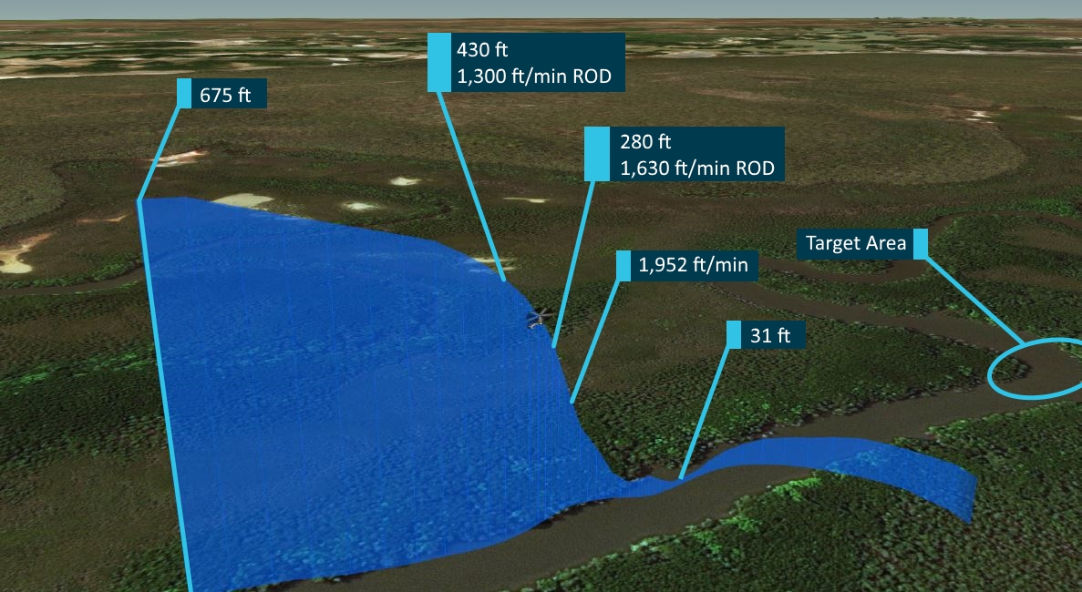
At 2110:30, the crew commenced an approach from the north to a point of interest in Salt Water Arm. The pilot reported visibility on approach to the target as good to the north-west, and dark to the north and east. During this approach, the pilot lost visual references. At 2110:40, the pilot activated HOV mode. At this time, the helicopter had already developed an undesired high rate of descent (Figure 2).

Figure 2: Flight path of VH-YHF during the event

Figure 2: Flight path of VH-YHF during the event.
Source: Leonardo interpretation of data from the Flight Data Recorder, annotated by ATSB

Source: Leonardo interpretation of data from the Flight Data Recorder, annotated by ATSB

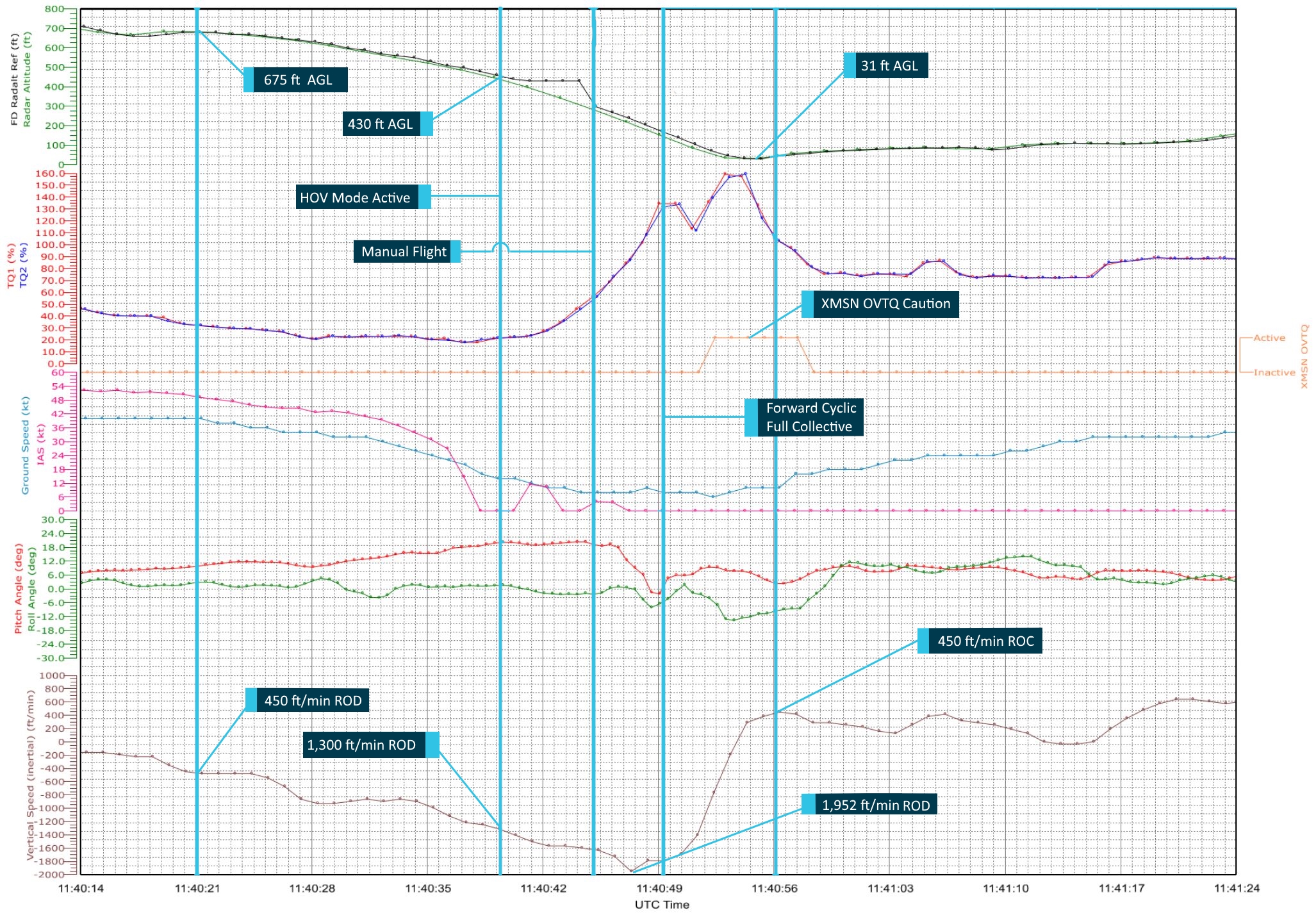
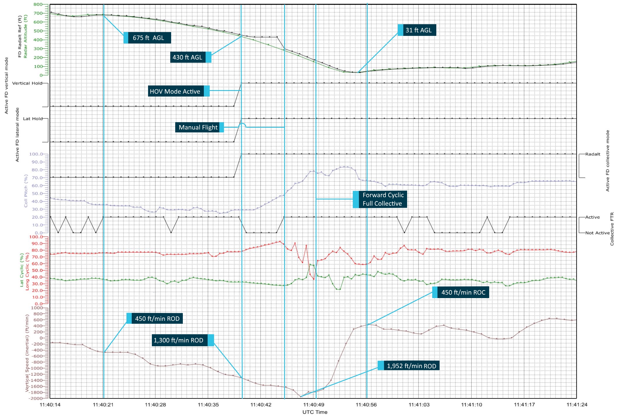
At the point of activation of HOV mode, the aircraft was at 430 ft, pitched 19.7 degrees nose-up, and descending at over 1,300 ft/min with a ground speed of 14 kt. The autopilot increased collective[6] pitch to 48 per cent to arrest the rate of descent.

Due to the lighting installed on the aircraft, and prioritisation of peripheral vision, the ACO could see the ground below and advised the pilot of a high rate of descent. The ACO provided advice twice more to the pilot before transitioning to an emergency call of ‘Climb! Climb! Climb!’ The pilot was by now receiving clear visual cues and detected a rapid rate of closure with the ground.

At 2140:46, at a height of 280 ft with a rate of descent of 1,630 ft/min, in a reversion to drilled emergency procedures, the pilot overrode aircraft automatics and used forward cyclic[7] and collective to reverse the rate of descent. The pilot directed his attention to the attitude indicator and the picture outside. The pilot increased collective pitch to 77 per cent. At this point, the rate of descent increased to 1,952 ft/min, indicative of onset of vortex ring state[8].

Maintaining forward cyclic, the pilot was aware of engine temperature limits and made a small reduction in collective to avoid exceeding the limits, before increasing collective again to 84 per cent.

At 2140:50, a yellow caution light illuminated and a crew alert system (CAS) message appeared on the display. Occupied with the recovery procedure, the pilot flew solely through the outside picture and the attitude indicator. The aircraft descended to a height of 31 ft AGL before attaining a positive rate of climb. As the pilot’s recovery manoeuvre ceased and control inputs returned to normal, the warning self-extinguished at 2140:57. The pilot noticed the warning, but could not read it before it extinguished.

It is likely that any further delay in conduct of the recovery drill would have led to an impact with terrain.

Return to base

The crew advised the RCC that they would end the flight and return to base. The crew landed the helicopter back at base at 2158. The pilot found that ash had accumulated on the fuselage of the helicopter, confirming flight through streams of smoke. During the flight through smoke, visibility was reduced below the visual minima.

A crew debrief took place and it was thought that a main gearbox overtorque could have occurred. There is no capacity in the aircraft for the crew to check for overtorque without the presence of an aircraft maintenance engineer (engineer). As a precaution, and as per Operations Manual requirements, the crew called a duty engineer to explain the situation and seek advice.

The duty engineer asked the crew to check the CAS system for messages. If an overtorque occurred, a white status message saying ‘maintenance’ would be present. This would signal a requirement to download and analyse data from the aircraft’s central maintenance computer (CMC).

The pilot estimated the extent of a potential overtorque to be within operational limits. The crew did not detect a maintenance message. With this information, the duty engineer advised that no maintenance activity was required.

Subsequent mission flight

Prior to the mission’s second flight, the crew thoroughly discussed the event. They developed a different strategy for the search to prevent reoccurrence, including the use of topography over the DF.

At 2254, the crew departed for the second flight to locate the source of the EPIRB transmission. The crew flew the arms of the river system at 1,000 ft using the autopilot, with the pilot flying with reference to instruments, and the ACO visually searching from the back.

The EPIRB was successfully located and noted to be in the bottom of a 14 ft metal-hulled recreational fishing boat. The boat carried two people and was in total darkness. As the vessel was unlit, the ACO could see the EPIRB flashing in the bottom of the boat. The position of the EPIRB had most likely resulted in the sporadic readout of the DF.

The helicopter crew directed a nearby Northern Territory Water Police vessel to the scene. The Water Police were then able to assist.

Detection of main gearbox overtorque

The following day, the crew related the experience to an engineer in the hangar and requested a download of the CMC data to check for potential issues. An overtorque of the main gearbox is recorded when a torque limit is exceeded. The limits for all engines operative are 110 per cent for five minutes, or 121 per cent for 5 seconds.

The engineer downloaded and analysed the data. An overtorque in excess of 125 per cent requires grounding of the aircraft, and analysis of the data by the engine and airframe manufacturers. He found that a main gearbox overtorque to 159.5 per cent had occurred during the first flight. The extent of the overtorque was such that the helicopter should not have been flown until the engine and airframe manufacturers declared the helicopter serviceable.

The engineer grounded the helicopter and sent data to the manufacturers of the engines and airframe for analysis. This meant that the crew had departed for their second flight of the previous evening in an aircraft of uncertain airworthiness.

Five days later, the engine manufacturer confirmed that the engines were undamaged and suitable for service. The helicopter manufacturer advised that the helicopter’s main gearbox was serviceable and required inspection of oil for metal contamination at 50 flight-hour intervals. The engineers carried out the necessary actions, and subsequently returned the helicopter to service.

__________

  1. Central Standard Time (CST): Coordinated Universal Time (UTC) + 9.5 hours.
  2. EPIRB: Emergency Position-Indicating Radio Beacon. A distress beacon which, when activated, broadcasts a 406 MHz signal to a network of satellites, and a 121.5 MHz signal for homing in on by search and rescue assets.
  3. Night Vision Goggles (NVG): A helmet mounted binocular device that intensifies ambient light, providing flight crew with improved vision at night.
  4. Night Vision Imaging System (NVIS): a system of internal and external lighting, combined with night vision goggles, which provides enhanced vision to crew for operation at night.
  5. Scattered clouds cover between three eights and one half of the visible sky.
  6. Collective: a primary helicopter flight control that simultaneously affects the pitch of all blades of a lifting rotor. Collective input is the main control for vertical velocity.
  7. Cyclic: a primary helicopter flight control that is similar to an aircraft control column. Cyclic input tilts the main rotor disc, varying the attitude of the helicopter and hence the lateral direction.
  8. Vortex Ring State: an undesirable state of powered flight where the helicopter settles in its own downwash.

Context

Personnel

Pilot

The pilot had over thirty-seven years’ experience in flying helicopters. He held an Airline Transport Pilot Licence (Helicopter) and instrument rating (Helicopter), authorising him to conduct night visual flight rules[9] (NVFR) and instrument flight rules[10] (IFR) operations as pilot. The pilot had gained experience around the world in military helicopter operations, onshore and offshore resource support, mountain flying, search and rescue, and ambulance helicopter operations. He held a current Class 1 Aviation Medical Certificate.

Table 1: Pilot’s rotary-wing hours accumulated

Total Time Rotary Wing9,800
Instrument Flight327.5
Night Flight833.0
AW139724.9

Source: Pilot

The pilot had more than 100 hours’ experience in command with night vision imaging systems (NVIS) and held a grade 1 NVIS rating. The operator’s training and checking system evaluated the pilot as level 2 night vision goggles (NVG).

The pilot achieved currency with an NVIS proficiency check on 9 May 2018. Notes on file advised the pilot to seek practice opportunities in order to consolidate skills for future upgrade to a level 1 NVG pilot. The report also noted that a lack of opportunity to practice was preventing the pilot from making best use of the aircraft’s automated systems.

The pilot’s roster pattern was week-on, week-off, performing 24-hour standby while rostered on. The most recent pattern started on 09 May 2018. In the 4 days prior to the incident, the pilot had accumulated 27.3 hours of duty and 5.8 hours of flight time. Within the Operator’s Fatigue Risk Management System[11] (FRMS), scores of 75 or less were considered consistent with safe working practices. The pilot’s score was 51. He reported feeling well and alert.

Aircrew Officer

The Aircrew Officer (ACO) had 23 years’ experience in crewing Search and Rescue (SAR) and Emergency Medical Services (EMS) helicopters as winch operator and down the wire rescue crewmember. He also held a Commercial Pilot Licence (Helicopter). His total experience in crewing helicopters was over 3,500 hours.

The ACO was NVIS and winch current, having undergone currency and proficiency flights on 10 and 12 May 2018. The Operator’s AW139 crewmembers all completed a pilot’s ground school course for the AW139. The ACO was trained and competent in front seat support and rear cabin activities. The ACO was rated as a Level 1 NVG crewmember within the operator’s system. He had over ten years’ NVIS experience, and he was part of a team that first integrated NVIS into company operations.

The ACO worked on a week-on, week-off, 24-hour standby roster. The ACO reported feeling well and rested at the time of the incident. The ACO’s score of 32 in the Operator’s FRMS supported this.

Flight Nurse

The Flight Nurse (FN) was a medical crewmember responsible for patient care, and not expected to be involved in the operation of the aircraft in flight.

Flight crew configuration

Exemption to operate with crewmember in rear cabin

The Civil Aviation Safety Authority (CASA) provided the Operator with an exemption to Supplement 60 of the AW139 rotorcraft flight manual. The exemption allowed the ACO to operate from the rear cabin of the aircraft during flight below 300ft and for landing at unimproved sites.

The Operator provided a risk analysis for landing at unprepared helicopter landing sites (HLS) under NVG to CASA in support of the exemption. For the descent and final approach phases, the identified risks were concerned with unintentional interference from the ground, obstacles, and loose objects. The helicopter manufacturer had no technical objection to the exemption on the provision that, amongst other things, the crewmember focussed on ensuring identification of obstacles.

Focussing on flight below 300 ft, the risk analysis provided for the initial exemption did not consider risks in the approach phase of flight relating to monitoring and the need for a single pilot to transition from outside goggle vision to instruments to supported peripheral vision. This exemption was later rendered unnecessary by an amendment to Supplement 60 in revision 22 of the AW139 rotorcraft flight manual on 19 October 2017. The manufacturer stated that they addressed risks during transition phase in the initial NVIS certification of the aircraft.

Climb-through

The Operator listed the responsibilities of an ACO in their operations manual as:

Under direction of the pilot assist with the operation of all aircraft equipment and systems during the conduct of VFR, NVG and IFR operations;

and

… operate the winch, dispatch, and recovery of personnel and assist the pilot in maintaining clearance from obstacles by lookout and reporting over the intercom.

Company ACOs could not carry out all of their duties from one location in the aircraft. The ACO had to climb between the front and back as operational requirements demanded. CASA’s position was that they supported the role of the ACO in the front left seat and did not support the transfer of the ACO from the front to rear of the cabin and vice versa in flight. CASA preferred operators to land for the ACO transfer through the aircraft to take place.

When responding to an emergency, the ACO would ordinarily begin the flight in the front and assist the pilot, then climb through to the rear to operate the winch as required. When an ACO used the climb-through, the company required the crew to file a report for data collection and analysis of the procedure.

On this flight, with no available landing sites on scene, and a short flight to the search area with anticipated use of the winch, the ACO began the flight in the back of the helicopter.

Aircraft information

General

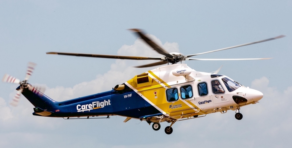
Leonardo Helicopter’s AW139 is a medium-sized twin-engine helicopter powered by two Pratt & Whitney PT6C-67C engines (Figure 3). Each engine is capable of producing take-off power of 1,252 kW. Each engine produces enough power for the aircraft to climb in the event of one of the engines failing. The main gearbox’s maximum limit for power from both engines is 1,641 kW. Therefore, overtorque of the transmission can occur when a pilot demands excessive engine power with both engines operative.

VH-YHF

AW139 serial number 31108 was registered in Australia on 18 February 2008 as VH-YHF, and at the time of the occurrence had flown 3,423 hours. The helicopter was certified and maintained for IFR and NVIS operations.

The helicopter’s autopilot was a 4-axis system with enhanced 3-cue flight director (FD). The FD is capable of controlling the helicopter’s movement in the pitch, roll, yaw, and vertical axis. The installed version of the FD had auto-hover functionality (HOV) mode, yet did not offer SAR modes that can mark, return, and transition down to a selected target.

Figure 3: AW139 helicopter VH-YHF

Figure 3: AW139 helicopter VH-YHF.
Source: Careflight

Source: Careflight

Auto-hover

HOV mode incorporates two systems to hold the aircraft at a point in space selected by the pilot. The first system controls the pitch and roll of the aircraft to maintain a zero ground speed in all directions. The second uses the barometric altitude or the radio altimeter[12] (RADALT) information and control of height to maintain the altitude selected by the pilot.

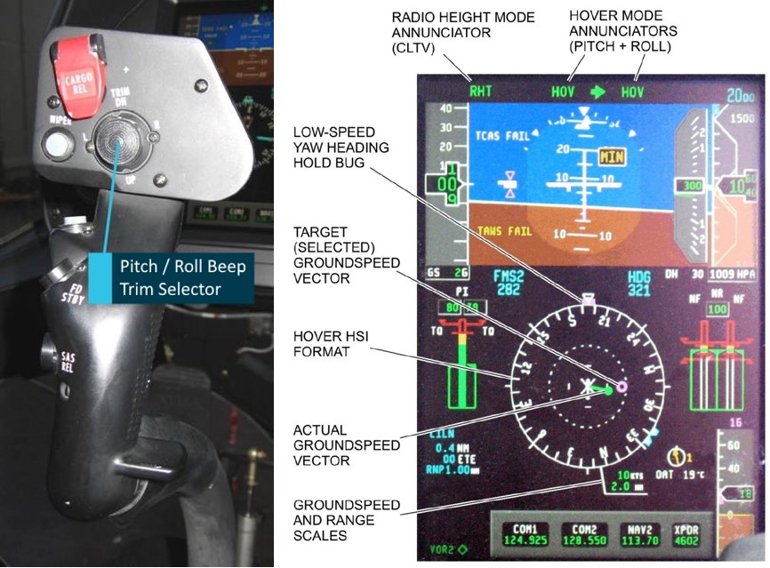
Aside from the panel-mounted autopilot controller, the pilot can activate both systems with the centre of the pitch/roll beep trim selector switch on the cyclic (Figure 4). With the airspeed below 75 kt, ground speed below 60 kt and altitude between 15 ft and 2,000 ft above ground level the system can be engaged. Engaging the system instructs the autopilot to make control inputs to bring the aircraft to a hover at the height showing on the RADALT at the time the pilot presses the switch. There was no vertical speed limit to engage HOV mode. The manufacturer did not intend for HOV mode to be engaged with a high vertical speed, though it did not preclude a pilot from doing so.

If engaged with a high vertical speed, the system would show as engaged and the autopilot would make adjustments necessary to attain the height designated by the pilot. This would induce a magnitude of overshoot relative to the vertical speed at time of engagement. A difference between the reference height and actual height would trigger a warning once large enough. For example, at a reference height of 500 ft, a message ‘HTLM’ appears on the PFD and ‘ALTITUDE, ALTITUDE’ sounds when the actual height passes below 430 ft.

Figure 4: Exemplar AW139 Cyclic and PFD showing HOV Mode engaged

Figure 4: Exemplar AW139 Cyclic and PFD showing HOV Mode engaged.
Source: Leonardo Helicopters, annotated by the ATSB

Source: Leonardo Helicopters, annotated by the ATSB

Crew Alert System

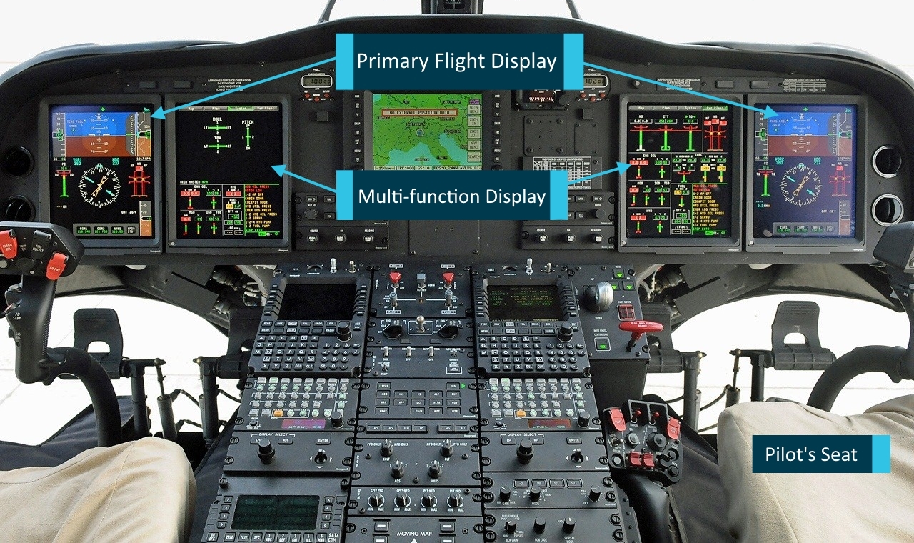
The primary flight display (PFD) and the multi-function flight display (MFD) present instrumentation to the pilot (Figure 5). The PFD displays FD modes selected, and their status. The MFD displays engine and aircraft system data and the crew alert system (CAS). The CAS displays messages pertaining to the operation and condition of the aircraft to the crew for information and action.

Figure 5: Exemplar AW139 cockpit displays

Figure 5: Exemplar AW139 cockpit displays.
Source: Leonardo Helicopters file photo, annotated by the ATSB

Source: Leonardo Helicopters file photo, annotated by the ATSB

The CAS messages appear in order of priority. Red warnings appear at the top of the list, next are yellow caution messages, third are green advisory messages, and fourth are white status messages. The final line in the list is white text stating ‘END.’ Each page shows twelve lines and crew can scroll through pages. When scrolling, red warnings cannot be hidden and remain at the top of the list on each page.

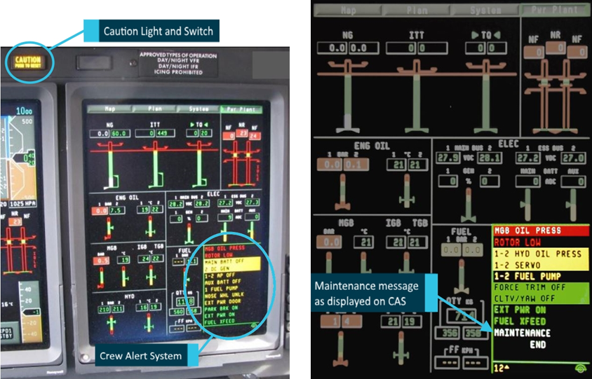
A warning or caution message will show with a coloured background until acknowledged. Once acknowledged, it appears as coloured text on a black background. Some messages such as “XMSN OVTQ” (main transmission overtorque) will disappear when the condition causing them has passed. White status messages will only show on the ground with weight on wheels (Figure 6).

The “MAINTENANCE” message is significant because following exceedance of a limit such as torque, it will illuminate after landing. The presence of the “MAINTENANCE” message is a cue to an aircraft maintenance engineer (engineer) to investigate and rectify the cause of the message before cancelling the message.

Figure 6: Exemplar caution light and maintenance message on CAS

Figure 6: Exemplar caution light and maintenance message on CAS.
Source: Leonardo Helicopters, annotated by the ATSB.

Source: Leonardo Helicopters, annotated by the ATSB.

Night vision imaging system

To improve vision during night operations, the helicopter crew utilised an NVIS. The operator was experienced in application of these technologies. They trained their own crews and offered NVIS training to other operators.

The operator’s NVIS comprises:

  • AN/AVS-9 green phosphor Night Vision Goggles (NVG)
  • NVG-compatible cockpit lighting
  • NVG-compatible cabin lighting
  • 2 x 450 W incandescent forward facing steerable search lights
  • 1 x 450 W incandescent steerable search light by winch
  • White flood lights at the front and back of the aircraft.

The operator mandated the use of NVIS for all visual flight rules (VFR) flights at night.

Goggle position

The human eye carries two sets of light-sensitive receptors: rods and cones. The cones are packed into the fovea, the central part of the retina responsible for focal vision. The rods populate the area of the retina used for peripheral vision. The way in which information from the focal regions and information from the peripheral regions is processed differs significantly (Miller & Tredici, 1992).

Peripheral vision is processed automatically and quickly. Humans utilise peripheral information to orientate themselves within their environment without even noticing. Focal vision requires conscious processing, which happens slowly and takes up cognitive resources (RTCA, 2001). The information delivered to the user through NVG is largely within the focal region. The cognitive resources required take away from other tasks requiring focal vision, such as interpretation of instruments (Salazar et al, 2003).

NVG offer a field of view (FOV) of 40° vertically and horizontally, much narrower than the 200° horizontally and 120° vertically most humans experience (Morawiec and others, 2007). Goggles are normally adjusted to a point where the central image is sharp, and the edge of the picture is slightly blurred yet becomes sharp when focussed upon. This puts the eyepiece approximately 25 mm from the eye.

This operator advised that they extend the NVG further away from the eye again. This reduces the FOV by a couple of degrees and increases the amount of peripheral vision available. This, in combination with copious white light, provides for increased peripheral vision when looking around the goggles below 400 ft in the obstacle environment.

This provides benefit in spatial orientation in low-level hover operations. The effect will be lost if peripheral cues become unreliable and obscure the target, such as happens with backscatter from obscurants like smoke.

White light

The use of white light is fundamental to this operator’s NVIS usage strategy. NVG-friendly[13] searchlights do not help in obstacle clearance as the NVG do not detect the light reflected by obstacles in the vicinity. White light (detectable by NVG) is amplified by the goggles and provides a clear image of where obstacles are. The crew moves the lights in a ‘scan and pause’ pattern with a wide swath either side of the planned approach and departure paths looking for obstacles.

The combination of peripheral vision and white light likely aided the ACO in his assessment of rate of closure and enabled his timely use of emergency phase Crew Resource Management (CRM).

NVIS approach procedure

Overhead the HLS or point of interest, the pilot marks the target on the GPS. The pilot then flies a circuit at 1,000 ft to set up an approach to the spot. Since the visual acuity afforded by the goggles does not provide ground cover detail until a height of 400 ft, the pilot must use instruments to monitor the progress of the aircraft, as per normal night flight procedures. The company operations manual highlights three critical instruments for the initial stage of the approach:

  • attitude indicator, to avoid incorrect attitude adversely affecting airspeed and rate of descent
  • vertical speed indicator, to make up for the reduced visual cues for rate of descent
  • radio altimeter, to incorporate a visual and audible warning that is set at 400 ft as a defence against unexpected rates of terrain closure

The pilot manually flies to a datum point of 400 ft above ground level (AGL) to attain the visual acuity required to identify the target. It is common to come to a hover at 400 ft to complete the reconnaissance and crew brief. The pilot can select HOV mode to pause. If there is a need to descend to winching height, the crew scans the approach and departure paths with searchlights using a ‘stop, scan, move’ process.

Once clear, the crew agrees to continue and the pilot eases the aircraft forward and down with the autopilot. ACO and pilot will work together to bring the aircraft to the best hover reference.

Meteorological information

During the shift, the pilot monitored weather reports and weather forecasts from sources at Darwin and surrounding airports, and the Bureau of Meteorology (BoM). The Aerodrome Forecast (TAF) for Darwin airport, valid for the duration of the flight, forecast wind as 6 kt from the south‑east, visibility of 10 km or greater, nil significant weather, and nil significant cloud below 5,000 ft. The aerodrome report matched the forecast precisely with the exception of showing wind to be 5 kt.

The BoM issued a Graphical Area Forecast (GAF) at 1332 Central Standard Time (CST), which carried a validity from 2030 CST for six hours. The planned operation was within area B2, and the operations were close to the boundary with B1. The GAF forecast scattered cloud with base 2,000 ft and tops to 10,000 ft in the area of B1. The forecast for the area B2 was visibility over 10 km reducing to 5,000 m with isolated areas of smoke below 7,000 ft. The crew reported that some of the conditions associated with B1 existed in their area of operation.

At 1923 CST, BoM published a new GAF. The new GAF showed visibility of 10 km reducing to 4,000 m with isolated areas of smoke below 7,000 ft in B2. Pilots utilising NVG must maintain visibility of 5,000 m at or above 500 ft above terrain or obstacles (Civil Aviation Order 82.6). In areas of smoke, visibility could be expected to be below that required for VFR flight at night.

Environmental conditions

On the night of the incident, there was very little celestial illumination. The moon had set at 1653 CST, and the sun had set at 1830 CST. The only light was starlight. Clouds obscured much of the starlight available.

Grass fires had been burning to the southeast of the region for several days. Smoke from the outlying grass fires drifted across the search area below 7,000 ft, reducing visibility in places. The operations manual mentioned smoke as a common cause of loss of visual reference, and pilots were required to memorise loss of visual reference drills.

The crew reported that these conditions had prevailed for a week. Training notes from a flight three days prior described similar conditions. The report stated:

…this flight was conducted on an especially difficult NT typical night – no moon, very low illumination, and smoke contamination.

Where operationally viable, the crew flew the helicopter above the smoke inversion, which they reported to be at around 1,000 ft.

Risk management of deteriorating weather and loss of visual references

The operator’s risk management profile recognised the risk of deteriorating weather and loss of visual references during a SAR operation. Among the potential consequences was loss of control leading to an aircraft accident. The management of the risk included controls for prevention of an occurrence, and for recovery should the event occur.

Prevention controls

Documented controls for the prevention of loss of visual references were:

  • Training and checking, to ensure that crews have relevant experience of similar conditions, all crew know how to assist in the approach and landing phase, and that procedures are being correctly followed.
  • Maintenance of good CRM, to ensure effective mission management and decision making aboard the aircraft.
  • Keeping the ACO current to assist the pilot with management of the flight.
Recovery controls

Recovery controls covered four aspects of operation:

  • Equipment fit, ensuring that the aircraft is appropriately equipped and has a functioning RADALT and Attitude Indicator.
  • Sound knowledge of procedures and limits for visual illusions and inadvertent instrument meteorological conditions (IIMC).
  • Crew preparedness: Use of simulator training to ensure crews have exposure to implementing correct technique in recovery procedures.
  • Crew Resource Management: Ensuring unambiguous and timely communication in situations requiring urgent action.

Beacon activation

Activating an emergency position-indicating radio beacon (EPIRB) begins a distress signal transmission on the 406 MHz frequency, which is detected by satellites. The transmission contains a code that identifies the registered owner of the EPIRB in a database. The Rescue Coordination Centre (RCC) can use the registration details to source information on the activation of the beacon, and contact the owner or a nominated emergency contact.

In this case, the EPIRB belonged to a Queensland-registered vessel, which was sold some time before without re-registration of the EPIRB. As a result, the RCC had no current contact details or information for the current owner of the EPIRB.

EPIRBs in Australia also transmit on the 121.5 MHz frequency. Search and Rescue Assets carry direction-finding (DF) equipment to home in on 121.5 MHz signals. When the beacon is correctly deployed, the DF shows the crew the direction the signal is coming from.

Similar occurrences

AO-2007-028

On 22 July 2007, the crew of a Bell 412 were searching for the source of an EPIRB transmission. The pilot was IFR-rated and the aircraft IFR-equipped. The crew were operating on a dark night with searchlights without NVG. There was smoke from active bushfires in the area.

During the approach, the pilot lost visual references due to the haze from smoke and dust in the atmosphere. The helicopter entered a high rate of descent. The aircrew officer called ‘zero airspeed.’ The pilot initiated recovery actions and the main gearbox was over-torqued in the recovery.

There was a landing site available and the pilot continued the approach from 200 ft AGL and inspected the helicopter after landing. The Bell 412 had a physical indicator that clearly indicated to the crew that overtorque had occurred.

AO-2009-077

In December 2009, the crew of a Bell 206L was conducting aerial work on a fire ground. The pilot was not IFR-rated and helicopter was not IFR-equipped. On take-off, the helicopter entered low cloud. The pilot lost control and the aircraft collided with the ground; the pilot was seriously injured and the passenger was fatally injured. There was no option for the pilot to conduct an IIMC drill to stabilise the aircraft and attain a safe profile.

AO-2016-160

On 21 October 2016, the crew of a BK 117-C2 were returning to base from carrying out an EMS mission. The pilot was IFR-rated and the aircraft was IFR-equipped. The flight was conducted under NVFR with NVIS. Conditions were marginal, and on departure, the helicopter entered low cloud.

The ACO declared loss of visibility on take-off. The pilot had poor visibility ahead yet could see well to the right. The pilot thought visibility would improve as they passed ground lighting that was reflecting in raindrops on the canopy.

The visibility did not improve, and the pilot slowed the aircraft to maintain visual meteorological conditions. The low-speed manoeuvre resulted in an undesired aircraft state and a terrain awareness warning activated. The pilot conducted an IIMC drill, restabilised control, and continued the flight before landing safely.

Aeromedical flights in the United States

In an analysis of aeromedical flights in the US, Aherne and others (2016) found that between 1995 and 2013, the US aeromedical industry had 32 fatal accidents resulting in 100 deaths. These flights were all single-pilot operations at night. All flights were operated under VFR, and two thirds of the fatal accidents occurred in instrument meteorological conditions (IMC).

__________

  1. Night Visual flight rules (NVFR): a set of regulations that permit a pilot to operate an aircraft only in weather conditions generally clear enough to allow the pilot to see where the aircraft is going, at night.
  2. Instrument flight rules (IFR): a set of regulations that permit the pilot to operate an aircraft to operate in instrument meteorological conditions (IMC), which have much lower weather minimums than visual flight rules (VFR). Procedures and training are significantly more complex as a pilot must demonstrate competency in IMC conditions while controlling the aircraft solely by reference to instruments. IFR-capable aircraft have greater equipment and maintenance requirements.
  3. Fatigue Risk Management System (FRMS): defined by ICAO as "a data-driven means of continuously monitoring and maintaining fatigue related safety risks, based upon scientific principles and knowledge as well as operational experience that aims to ensure relevant personnel are performing at adequate levels of alertness".
  4. Radio Altimeter: a device that detects phase shift between a transmitted and a reflected radio signal, to calculate the height of the aircraft from terrain directly below it. Also known as Radar Altimeter.
  5. NVG-friendly: a light system that excludes frequencies detected by the NVG. The intent is for a light to be available for crews that does not dazzle the NVG wearer.

Safety analysis

Introduction

During an approach to a potential search and rescue target, smoke from nearby bushfires affected the visibility for the flight crew. The helicopter developed an uncommanded high rate of descent, and the aircrew officer in the rear alerted the pilot, at which point a recovery was enacted. The recovery manoeuvre resulted in an airframe limitation exceedance, which went undetected for the subsequent flight.

This analysis will examine the operator’s risk management, degraded visual environments, single pilot operations, and airframe limitation exceedance management.

Operator’s risk controls

On this occasion, prevention controls failed and recovery controls worked to save the aircraft and crew. There were, however, gaps in the implementation of all of the documented controls:

  • Training and checking achieved the aim of creating relevant experience, yet an identified limited practice opportunity reduced efficacy.
  • Crew resource management (CRM) lapsed in a missed announcement of loss of visual references. CRM was, however, restored to good effect in recovery.
  • The aircrew officer (ACO) was trained yet not positioned to assist the pilot in managing the approach.

There were no preventative controls that helped crews to define limits of visibility beyond the description of visual flight rules (VFR) minima.

The operations manual stated:

Illumination levels are significantly affected by moon position and strength, cloud presence, and cultural lighting and during NVG operations; illumination levels have a profound effect on the ability of the NVG to clearly discern terrain at distance. Visibility is also affected by the usual day time issues of dust, snow, moisture, bushfire smoke and other atmospheric obscurants.

However, the operations manual offered no guidelines on interpretation of factors affecting visibility or definition of acceptable limits. This meant the crew had to interpret marginal conditions during operations and decide if the minima were sufficient. This meant that the organisation did not set its own tolerance for risk in this regard.

During the event, CRM, the well-rehearsed recovery drill, and use of the attitude indicator were all vital in recovering control of the aircraft. The documented and implemented recovery controls worked as intended.

Contribution of night vision imaging system

Studies have shown that night vision goggles’ (NVG) performance can lead pilots to revert to a daytime model of operation (Rash, 2010), leading them to overlook the threats and complexities of operating with NVG. The operator’s operations manual clearly reminded crew that NVG does not turn night into day, and that the use of NVG carries limitations and risk.

Low-contrast Terrain

The search area was an area of low-contrast terrain for night vision imaging systems (NVIS) operations. This meant that elements of the terrain reflected similar amounts of celestial light, creating a low-quality image in the NVG. This lack of detail reduced visual cues. The reduction in visual cues most likely led to difficulty in perceiving the aircraft’s attitude and estimation of terrain clearance (Parush et al., 2011).

Obscurants

Airborne particles affect the image that NVG produce. The cues that would normally be relied upon for loss of visual meteorological conditions (VMC)[14] may not be present. Operating unaided, light sources begin to disappear as obscurants increase. Under NVG, as obscurants reduce the light energy reaching the goggles, NVG will continue to amplify the light signal, disguising the worsening visibility (see CAAP 174-01 11). There will be steady reduction in image quality outside of the bright spots as signal to noise ratio reduces. Scintillation[15] in the image will occur.

Sighting pinpoints of bright light over long distances does not mean that visibility is in excess of 5 km. Visibility must be measured by the distance detail can be seen on the ground. If a pilot using NVG can see lights but no ground detail, they may be in or very close to instrument meteorological conditions (IMC).[16] An early decision to use a recovery drill if visual references are lost is also vital to ensure entry into IMC does not develop into a loss of control or controlled flight into terrain.

Degraded visual environment

Conditions of degrading visibility create ambiguity. This ambiguity can stall decision-making, as two contextually different situations are faced (Orasanu and others, 2001). Either the approach continues and the target is assessed, or the approach is aborted and the mission is delayed.

Pilots rely on appropriate visual cues to assess quickly and accurately the aircraft’s current and future situation. Darkness, even while utilising a NVIS, reduces availability of these cues. No one is immune to these phenomena and strict adherence to an instrument scan on night approach is the primary protection available.

Pilots tend to underestimate the likelihood of loss of control and overestimate their ability to continue to control the aircraft if visual references are lost (Wiggins and others, 2012). The cues for IMC are an absence of those for VMC. The search area for cues to resolve the ambiguity is external to the aircraft, and as such, attention can be drawn outside (Summerfield & Egner, 2009).

Humans also often incorrectly believe that changes will be easy to detect in their environment. Unless someone observes a change while it is taking place, there is a good chance it will not be picked up (Wickens & McCarley, 2008). While searching outside for cues, changes on instruments can be missed. These missed changes can lead a pilot to believe that their knowledge of their position and trajectory in space is accurate. This belief leads to a reduction in the search for new information or information to the contrary (Wickens & McCarley, 2008).

Above 400 ft, the approach should be predominantly made with reference to instruments (see CAAP 174-01 D.3). The pilot was primarily using goggle vision and looking outside. The narrow field of view of the NVG’s requires a demanding and deliberate scan pattern to integrate the outside with instruments. As the pilot slowed to below 45 kt with reducing visual cues, the picture outside was not giving enough information to manage the closure rate of the aircraft. This resulted in a loss of the ability to recognise, with any accuracy, the aircraft’s position and trajectory.

Single-pilot operation

Monitoring is a fundamental tool to boost threat and error management (Flight Safety Foundation, 2014). Furthermore, inadequate monitoring is related to a high number of approach and landing accidents. While there is a clear benefit to multi-crew operations, there is no requirement for multi-crew in Australian search and rescue (SAR), and emergency medical services (EMS). SAR/EMS Operators in Australia tend to perform reduced crew flight operations, whereby extra crewmembers are called upon only for periods of vulnerability.

Crew in the back of an AW139 cannot hear alarms from the cockpit. The 400 ft warning from the Radio Altimeter (RADALT) and the 150 ft warning from the aircraft are only available to front seat crew. The aircraft descended through 400 ft at 1,430 ft/min. The pilot resumed manual control at the time of the emergency climb call as the aircraft passed through 280 ft, 3.5 seconds later.

Had there been a second person in the cockpit monitoring the approach, their first indication of a loss of visual reference, if not announced by the pilot, would most likely be an unusual combination of attitude and vertical speed. The aircraft had developed an unusually high 900 ft/min rate of descent 12 seconds before passing through 400 ft. This information may take a monitoring Aircrew Officer (ACO) a second or two to process. Once processed, however, the aircrew officer (ACO) is in a position to call for a go-around, and to provide accurate information to the pilot regarding the aircraft state much sooner in the sequence.

While facing a high risk of encountering a degraded visual environment, the requirement to have the ACO in the rear cabin for winch operations degraded the crew’s defences against loss of control. The addition of another trained crewmember would be an ideal risk control for operations in potentially degraded visual environments.

Caution and maintenance messages

There is no option for the crew to review caution messages once the message has self‑cleared, or to interrogate the system to discover the extent of any exceedance. As the main transmission torque limit exceedance message (XMSN OVTQ) was missed because it appeared during a time of high workload in flight, the crew could not know of the nature and extent of the exceedance without the support of an aircraft maintenance engineer (engineer).

The crew and the engineer who downloaded the data the following day reported that no maintenance message was detected on the crew alert system (CAS). Analysis of the central maintenance computer (CMC) log showed that eight minutes before the incident flight, a maintenance message activated for 41 seconds. A maintenance message again illuminated four minutes after landing for 31 seconds until shutdown.

The crew reported that the maintenance message was overly generic and related to a host of issues, ranging from critical to inconsequential. The only way to determine the meaning of the message was for an engineer to access the CMC through a laptop. Given the remote locations and 24‑hour nature of operations, engineer access was often impractical, and some telephone diagnosis had to take place.

Additionally, a software update had previously caused issues by instructing the aircraft that equipment it did not have was fitted. As a result, numerous maintenance messages related to the failure of the non-existent equipment were seen. This nuisance message issue was resolved 6 months prior to the event.

These nuisance alerts and generic nature of the message could combine to dilute the significance of the maintenance message and reduce the likelihood that crews would seek out and respond to genuine alerts.

Automatic hover mode use

The autopilot’s automatic hover (HOV) mode fitted to the helicopter could be engaged while the helicopter had a high rate of descent. If this system was not explicitly understood, the pilot may believe that HOV mode had adequate control of the aircraft upon activation. It would display as engaged even though it could be subject to a considerable overshoot, outside of the system’s capacity to recover before impact with terrain. At the height engaged, the mismatch between reference height and actual radar height would have triggered a PFD message ‘HTLM’ and an aural callout of ‘ALTITUDE, ALTITUDE’ after about 2.5 s, as the aircraft passed through a point between 39 ft and 70 ft below the reference height. The pilot input came 4.2 s after engagement of automatic hover. Without the correct mental model of HOV mode operation, time taken to interpret autopilot performance may have delayed manual recovery actions.

Beacon registration and placement

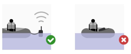
When the vessel was located, the crew saw the emergency position-indicating radio beacon (EPIRB) laying in the bottom of the boat and not deployed as per Australian Maritime Safety Authority guidance. This resulted in a scattered signal and created inaccuracies in the operation of the Direction Finder (DF). The crew could not resolve the direction of the beacon.

The lack of accurate registration details and sporadic output of the DF caused distraction to the crew and increased their time to find the target. The result for the crew was that they were required to identify a number of targets and make approaches to them for visual identification. This increased the complexity and time taken to complete the operation.

Figure 7: Correct EPIRB placement following activation

Figure 7: Correct EPIRB placement following activation.
Source: Australian Maritime Safety Authority

Source: Australian Maritime Safety Authority
__________

  1. Visual Meteorological Conditions (VMC): an aviation flight category in which visual flight rules (VFR) flight is permitted – that is, conditions in which pilots have sufficient visibility to fly the aircraft while maintaining visual separation from terrain and other aircraft.
  2. Scintillation: rapid changes in brightness at random points which to the viewer looks like a sparkling effect across the image.
  3. Instrument meteorological conditions (IMC): weather conditions that require pilots to fly primarily by reference to instruments, and therefore under Instrument Flight Rules (IFR), rather than by outside visual reference. Typically, this means flying in cloud or limited visibility.

Findings

From the evidence available, the following findings are made with respect to the loss of control of a Leonardo Helicopters AW139, registered VH-YHF, on 13 May 2018, and the subsequent release of the aircraft without a required inspection. These findings should not be read as apportioning blame or liability to any particular organisation or individual.

Contributing factors

  • During the search for a transmitting beacon, the helicopter crew planned to approach to a hover near a target. However, low celestial illumination and drifting smoke created a high risk of encountering a degraded visual environment. This resulted in a loss of visual references on approach.
  • During the approach to hover in a degraded visual environment, searching outside for visual cues drew the pilot’s attention away from the flight instruments. This resulted in flight instruments not being referenced when they were needed.
  • The required position of the aircrew officer in the rear of the helicopter prior to descent negated the benefit of having a trained and competent crewmember to assist the pilot, resulting in a degraded monitoring capability in the approach to hover.
  • While on approach in a degraded visual environment, without the protections of flight instrument use or monitoring, the helicopter entered an uncommanded, undetected high rate of descent, resulting in a transmission overtorque during recovery.

Other factors that increased risk

  • Auto hover had no design limit on vertical speed for engagement, which permitted overshoot following engagement with high rate of descent.
  • As the aircrew could not confirm the existence of an exceedance, and a maintenance message was not detected on the Crew Alert System, the aircraft was operated despite requiring an inspection.

Other findings

  • Application of good Crew Resource Management and practiced recovery techniques supported the crew in restoring control.
  • The emergency position-indicating radio beacon was not registered to the current owner, and was incorrectly placed in the boat. The placement scattered the beacon's signal, leading to loss of accuracy in direction-finding equipment. As a result, mission complexity and time taken to rescue were increased.

Sources and submissions

Sources of information

The sources of information during the investigation included:

  • the pilot and crew
  • Careflight
  • Aviation Specialities Unlimited
  • the Bureau of Meteorology
  • Airservices Australia
  • Leonardo Helicopters
  • the Civil Aviation Safety Authority.

References

Aherne BB and others, 2016, Pilot Domain Task Experience in Night Fatal Helicopter Emergency Medical Service Accidents, Aerospace Medicine and Human Performance. 87(6). 550-556.

Arthur W and others, 1998, Factors That Influence Skill Decay and Retention: A Quantitative Review and Analysis, Human Performance. 11(1), 57-101.

Australian Transport Safety Bureau, 2004, ASR B2004/0152, Night Vision Goggles in Civil Helicopter Operations

Bailey RE and others, 2017, An Assessment of Reduced Crew and Single Pilot Operations in Commercial Transport Aircraft Operations, 2017 IEE/AIAA 36th Digital Avionics Systems Conference, St Petersburg

Biggs AT and others, 2015, Examining perceptual and conceptual set biases in multiple-target visual search, Atten Percept Psychophys. 77. 844-855.

Civil Aviation Authority, 2013, CAP 739, Flight Data Monitoring

Civil Aviation Safety Authority, 2017, CAAP 174-01 v2.1, Night vision imaging – helicopters

Dismukes RK & Berman B, 2010, Checklists and Monitoring in the Cockpit: Why Crucial Defenses Sometimes Fail, National Aeronautics and Space Administration, Moffett Field

Ersting J & King P, 1995, Aviation Medicine, 2nd ed., Butterworth-Heinemann Ltd, Oxford.

Flight Safety Foundation, 2014, A Practical Guide for Improving Flight Path Monitoring, Washington.

Flight Safety Foundation, 2018, Position Paper: Pilot training and competency, Alexandria.

Miller RE & Tredici TJ, 1992, Night Vision Manual for the Flight Surgeon, Armstrong Laboratory, AL-SR-1991-0002

Morawiec G, Niall KK & Scullion K, 2007, Distance estimation to flashes in a simulated night vision environment, Defence R&D Canada, TR 2007-143

Orasanu J & Martin L, (1998). Errors in aviation decision making: A factor in accidents and incidents. In Proceedings of the Workshop on Human Error, Safety, and Systems Development. 100-107.

Orasanu J, Martin L & Davison J, (2001). Cognitive and contextual factors in aviation accidents, in Salas E and Klein G (Eds.) Linking expertise and naturalistic decision making, Lawrence Erlbaum Mahwah NJ. 209–226.

Parush A, Gauthier M, Arseneau L & Tang D, (2011). ‘The Human Factors of Night Vision Goggles Perceptual, Cognitive, and Physical Factors’, Reviews of Human Factors and Ergonomics. 7. 238-279.

Previc FH & Ercoline WR, 2004, Spatial Disorientation in Aviation, American Institute of Aeronautics and Astronautics, Inc., Reston.

Rash CE, 2010, ‘Lighting Up the Night’, Aero Safety World. August 2010. 14-18.

Robson D, Night Flight, 2008, Aviation Theory Centre, Cheltenham.

RTCA 2001, Concept of Operations: Night vision imaging systems for civil operators, RCTA/DO-268, RTCA, Washington, D.C.

Salazar G and others, 2003, Civilian use of night vision goggles, Aviation Space and Environmental Medicine. 74. 79-84.

Summerfield C & Enger T, 2009, Expectation (and attention) in visual cognition, Trends in Cognitive Sciences. 13(9). 403-409.

Wickens CD & McCarley JS, 2008, Applied Attention Theory, CRC Press, Boca Raton

Wiggins MW and others, 2012, ‘Characteristics of pilots who report deliberate versus inadvertent visual flight into instrument meteorological conditions’, Safety Science. 50(3). 472-477.

Wiggins MW and others, 2014, ‘Cue-utilisation typologies and pilots’ pre-flight and in-flight weather decision-making’, Safety Science. 65. 118-124.

Submissions

Under Part 4, Division 2 (Investigation Reports), Section 26 of the Transport Safety Investigation Act 2003 (the Act), the Australian Transport Safety Bureau (ATSB) may provide a draft report, on a confidential basis, to any person whom the ATSB considers appropriate. Section 26 (1) (a) of the Act allows a person receiving a draft report to make submissions to the ATSB about the draft report.

A draft of this report was provided to the Civil Aviation Safety Authority, the Bureau of Meteorology, Leonardo Helicopters, the crew of VH-YHF, engineers for VH-VHF, and Careflight.

Submissions were received from the Civil Aviation Safety Authority, the Bureau of Meteorology, Leonardo Helicopters, the crew of VH-YHF and Careflight. The submissions were reviewed and, where considered appropriate, the text of the report was amended accordingly.

Appendix A: Flight data

Figure 8: Incident flight data

Figure 8: Incident flight data.
Source: Operator / Leonardo Helicopters, annotated by the ATSB

Source: Operator / Leonardo Helicopters, annotated by the ATSB

Figure 9: Incident flight data

Figure 9: Incident flight data.
Source: Operator / Leonardo Helicopters, annotated by the ATSB

Source: Operator / Leonardo Helicopters, annotated by the ATSB

Purpose of safety investigations & publishing information

Purpose of safety investigations

The objective of a safety investigation is to enhance transport safety. This is done through:

  • identifying safety issues and facilitating safety action to address those issues
  • providing information about occurrences and their associated safety factors to facilitate learning within the transport industry.

It is not a function of the ATSB to apportion blame or provide a means for determining liability. At the same time, an investigation report must include factual material of sufficient weight to support the analysis and findings. At all times the ATSB endeavours to balance the use of material that could imply adverse comment with the need to properly explain what happened, and why, in a fair and unbiased manner. The ATSB does not investigate for the purpose of taking administrative, regulatory or criminal action.

Terminology

An explanation of terminology used in ATSB investigation reports is available here. This includes terms such as occurrence, contributing factor, other factor that increased risk, and safety issue.

Publishing information 

Released in accordance with section 25 of the Transport Safety Investigation Act 2003

Published by: Australian Transport Safety Bureau

© Commonwealth of Australia 2020

image_5.png

Ownership of intellectual property rights in this publication

Unless otherwise noted, copyright (and any other intellectual property rights, if any) in this report publication is owned by the Commonwealth of Australia.

Creative Commons licence

With the exception of the Coat of Arms, ATSB logo, and photos and graphics in which a third party holds copyright, this publication is licensed under a Creative Commons Attribution 3.0 Australia licence.

Creative Commons Attribution 3.0 Australia Licence is a standard form licence agreement that allows you to copy, distribute, transmit and adapt this publication provided that you attribute the work.

The ATSB’s preference is that you attribute this publication (and any material sourced from it) using the following wording: Source: Australian Transport Safety Bureau

Copyright in material obtained from other agencies, private individuals or organisations, belongs to those agencies, individuals or organisations. Where you wish to use their material, you will need to contact them directly.

Occurrence summary

Investigation number AO-2018-039
Occurrence date 13/05/2018
Location 38 km east-north-east of Darwin
State Northern Territory
Report release date 16/04/2020
Report status Final
Investigation level Defined
Investigation type Occurrence Investigation
Investigation status Completed
Mode of transport Aviation
Aviation occurrence category Loss of control
Occurrence class Serious Incident
Highest injury level None

Aircraft details

Manufacturer Leonardo Helicopters
Model AW139
Registration VH-YHF
Serial number 31108
Aircraft operator Careflight
Sector Helicopter
Operation type Aerial Work
Departure point Darwin, Northern Territory
Destination Darwin, Northern Territory
Damage Nil

Loss of control and collision with terrain involving Cirrus SR22, VH-PDC, Orange Airport, New South Wales, on 15 May 2018

Final report

Report release date: 06/06/2019

Safety summary

What happened

On 15 May 2018, at 1903 Eastern Standard Time, a Cirrus SR22 aircraft, registered VH‑PDC, collided with terrain at Orange Airport, New South Wales. The accident was a night training flight with one pilot (aircraft owner) and one flight instructor on board. The pilot and instructor were seriously injured and the aircraft destroyed.

What the ATSB found

The ATSB found that the pilot, who was conducting his first night training flight, likely became spatially disorientated during a go-around manoeuvre, which resulted in a loss of control at low level and collision with terrain.

The flight instructor did not intervene to take control of the aircraft during the go-around manoeuvre, because she was not aware the pilot had become spatially disorientated and was accustomed to directing the pilot to correct control problems. Inconsistent with Civil Aviation Safety Authority guidance, the instructor, who had previously instructed the pilot for his private instrument rating, did not provide a night flying demonstration before directing the pilot around the circuit.

Safety message

It is important for flight instructors to provide a demonstration when introducing a pilot to a new flight sequence or new flight environment. Time spent demonstrating the key points of a new sequence or environment will usually improve the learning process by ensuring that the development of a new skill is supported and preceded by knowledge and understanding from experience.

The flight instructor reported that for the delivery of future initial night flying training, she would conduct either a separate session of daytime flying training circuits prior to night, or deliver the training as day-into-night circuit training. She also commented that, prior to teaching night flying, flying training organisations should consider conducting refresher training in unusual attitude recoveries, irrespective of a pilot’s level of experience and qualifications.


The occurrence

On 15 May 2018, at 1903 Eastern Standard Time,[1] a Cirrus SR22 aircraft, registered VH‑PDC, collided with terrain at Orange Airport, New South Wales. The accident was a night training flight with one pilot (aircraft owner) and one flight instructor on board. The pilot and instructor were seriously injured and the aircraft destroyed.

The pilot held a private instrument rating and the accident flight was the pilot’s first training flight for a night endorsement to be added to his rating.[2] The instructor arrived at the hangar in the evening, just as the pilot was completing his pre-flight inspection of the aircraft. They completed the inspection together and then the instructor delivered a night flying brief to the pilot. The briefing included the physiological effects of the night environment, procedural differences for the night circuit, and the instrument and visual sections of the night circuit, which included the need to transition onto instruments on rotation during take-off.

The pilot and instructor boarded the aircraft and completed all the checklist items on the multi‑function display (MFD). The wind appeared to be light and variable and they selected runway 11 for the circuits. The pilot activated the runway lighting while taxiing,[3] which also provided precision approach path indicator (PAPI) lighting.[4]

The instructor directed[5] the pilot throughout the first touch-and-go[6] circuit to runway 11, which she considered was flown to a good standard with the pilot responding to her direction. On the second circuit, at about 500 ft above ground level on approach to land, the pilot and instructor noted the approach was too steep. The pilot, with direction from the instructor, corrected the approach and they both observed two‑white and two-red PAPI lights on short final approach, which indicated they were on the correct approach path. The pilot flared the aircraft a ‘little high’ for the touchdown, and the aircraft bounced twice. The pilot elected to go-around and applied full power before touching down again.

When full power was applied, the aircraft pitched[7] up. As the pilot was attempting to transition his scan onto the instruments, the instructor, whose attention was on the attitude indicator,[8] directed him repeatedly to level the wings—‘wings level’. The pilot observed the runway lights disappear off to the right and felt the aircraft was in a roll[9] as he was trying to focus his attention on the attitude indicator.[10] Following a review of the ATSB’s draft investigation report, the pilot also reported that he manipulated the flight controls in an attempt to recover the aircraft. Shortly after, the aircraft collided with the ground, struck a fence and came to rest inverted.

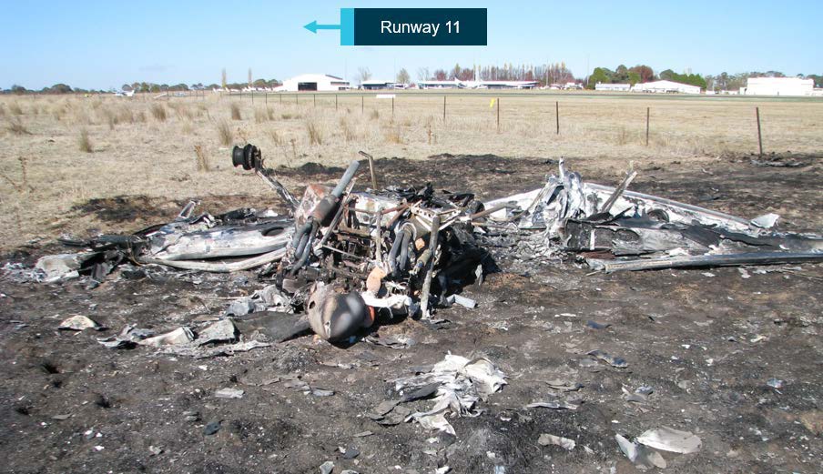
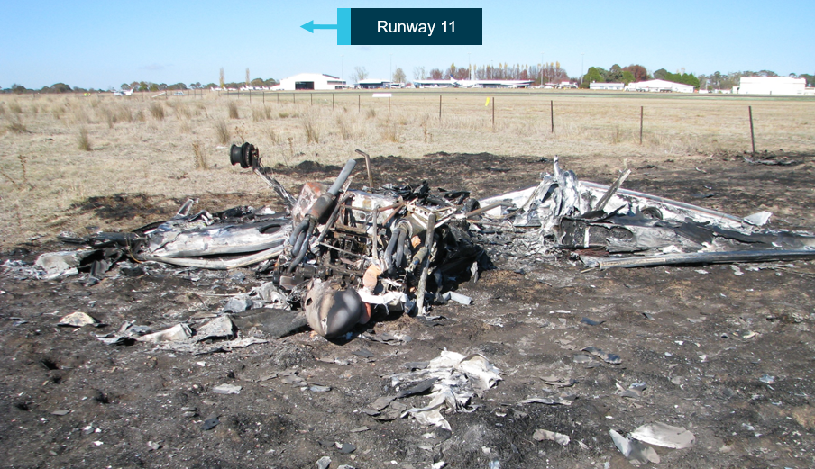
The pilot reported that he ‘kicked the pilot’s door window out’ to exit the aircraft, at which stage the wings were alight and a grass fire had started.[11] He then pulled the instructor out of the wreckage, who had lost consciousness after becoming disorientated while looking for the emergency egress hammer.[12] Emergency services located at the airport immediately responded to the accident. Figure 1 shows the wreckage site with reference to runway 11. Weather conditions were not considered a contributing factor to the accident.

Figure 1: VH-PDC wreckage

Figure 1_7.jpg

Source: ATSB

__________

  1. Eastern Standard Time (EST): Coordinated Universal Time (UTC) + 10 hours.
  2. A pilot who has a private instrument rating is authorised to operate at night under the instrument flight rules only if that pilot holds a night private instrument endorsement.
  3. Pilot activated lighting (PAL) is activated by a pilot keying a series of transmissions, within a specified timeframe, on a specified radio frequency.
  4. PAPI is a visual aid that provides pilots with guidance on acquiring and maintaining the correct approach path to a runway. The system consists of four side-by-side lights positioned next to the runway. When the aircraft is on the desired approach path (3°), two red and two white lights will be visible. More than two red lights indicates the aircraft is low on approach, and more than two white lights indicates the aircraft is high.
  5. Airborne instruction is based on a building block approach using demonstrate, direct then monitor. The instructor flies the sequence in demonstrate, provides verbal commands to the student in direct and observes the student’s progress in monitor.
  6. A procedure whereby an aircraft lands and takes off without coming to a stop.
  7. Pitching: the motion of an aircraft about its lateral (wingtip-to-wingtip) axis. Increased thrust over the tailplane will increase the tailplane down force and pitch the nose upward.
  8. Attitude indicator is a primary flight instrument, which displays the aircraft pitch and roll against an artificial horizon.
  9. Rolling: the motion of an aircraft about its longitudinal axis.
  10. The Cirrus SR22 aircraft’s propeller rotates clockwise, as viewed from the pilot’s seat. Therefore, an increase in power will increase the engine torque reaction and propeller slipstream. Without pilot input, the natural response from the aircraft is to roll and yaw (motion of an aircraft about its normal axis) to the left.
  11. The fence was electrified, but it was not determined if the fence or the engine was the ignition source for the fire.
  12. An eight-ounce ball-peen type hammer is located in the centre armrest. If the cabin doors are jammed or inoperable, the hammer may be used to break through the acrylic windows.

Context

Pilot information

The flight instructor held a valid Commercial Pilot Licence (Aeroplane), a Grade 1 flight instructor rating, an instrument rating and a night visual flight rules rating. She had a total flying experience of about 4,200 hours and last completed a flight review on 3 December 2017.

The pilot held a valid Private Pilot Licence (Aeroplane) and a private instrument flight rules rating. He last completed a flight review on 11 March 2017 (private instrument rating), had accrued about 500 hours on Cirrus aircraft, and about 50 hours of instrument flight time. The pilot had conducted the majority of his training and subsequent flying from Orange Airport, where his aircraft had been hangered.

Closed-circuit television footage

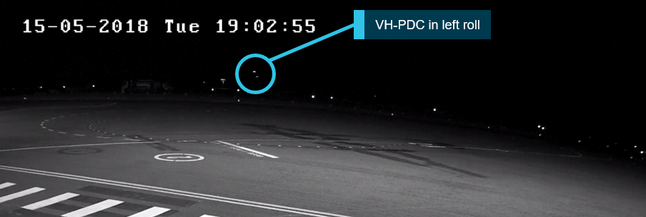
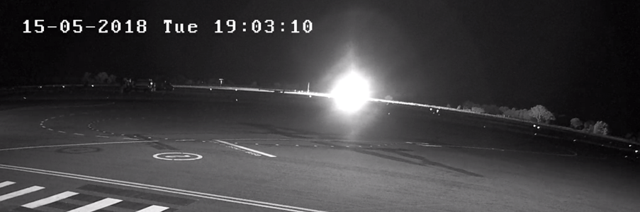
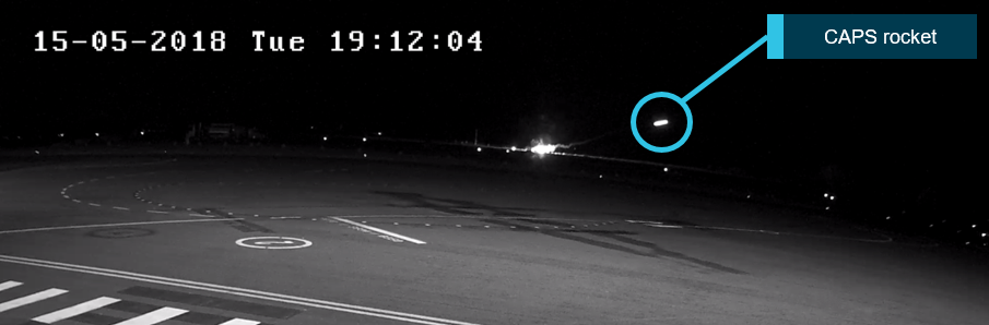
Closed-circuit television footage from Orange Airport depicted the aircraft rolling left at a low height above runway 11 before impacting the ground on the north-east side of the runway at 1903. A small fire ensued after impact, followed by deflagration of the fuel vapour about 7 seconds later. About 9 minutes later, the CAPS[13] rocket fired. Figures 2, 3 and 4 depict the initial roll of the aircraft, deflagration of the aircraft fuel vapour and firing of the CAPS rocket.

Figure 2: VH-PDC in left roll

Figure 2: VH-PDC in left roll

Source:  Orange City Council, annotated by the ATSB

Figure 3: Deflagration of fuel vapour

Figure 3: Deflagration of fuel vapour

Source:  Orange City Council

Figure 4: CAPS rocket

Figure 4: CAPS rocket

Source:  Orange City Council, annotated by the ATSB

Aircraft information

Electronic stability and protection

Before take-off, the pilot checked the aircraft’s autopilot and then switched it off. When the autopilot is switched off, the aircraft’s electronic stability and protection (ESP) system is operational. The ESP system automatically activates the autopilot servos to recover the aircraft from excessive roll and pitch attitudes.

The ESP roll protection activates at 45° roll angle, reaches a maximum stick force at 50°, and disengages when the roll angle reduces to 30°. The ESP pitch protection engages at 17.5° nose up, reaches a maximum stick force at 22.5° and disengages at 12.5°. Although the ESP uses the autopilot servos to drive the controls, the pilot retains the ability to override the system.

Recorded data

VH-PDC carried a Garmin G1000 avionics package, and a Recoverable Data Module (RDM). The G1000 is capable of recording various parameters to a secure digital (SD) card, installed on the upper slot of the MFD. The same information is recorded to the RDM, which is an impact and fire resistant unit,[14] installed on the vertical fin spar. The RDM and MFD modules were removed from the aircraft for examination by the ATSB.

The RDM was recovered from the severely fire damaged fin. The rear portion of the module was exposed to a high temperature and showed external heat damage. Disassembly of the crash hardened enclosure to access the data storage components revealed extensive fire damage to the memory devices. No data was recovered from this device.

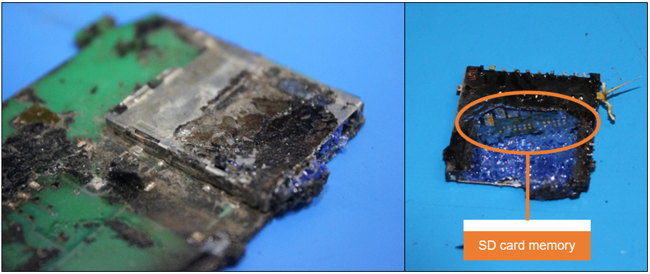
Initial observations of the MFD SD card slots revealed they were substantially fire damaged and retained two SD cards; the top slot contained the data logging card, the bottom slot contained the Garmin database card. To access the cards, the MFD was disassembled, and the circuit board holding the two cards was removed. The data logging card was found to be substantially damaged (Figure 5). The encapsulated memory device was removed from the data logging card and cleaned. The data logs were then extracted with a modified SD card reader. A total of 241 flight logs were recovered, including the accident flight (Figure 6).

Figure 5: Data logging SD card

Figure 5: Data logging SD card

Left: Removed MFD slot with data logging SD card. Right: removed data logging card with card memory identified. 
Source:  ATSB

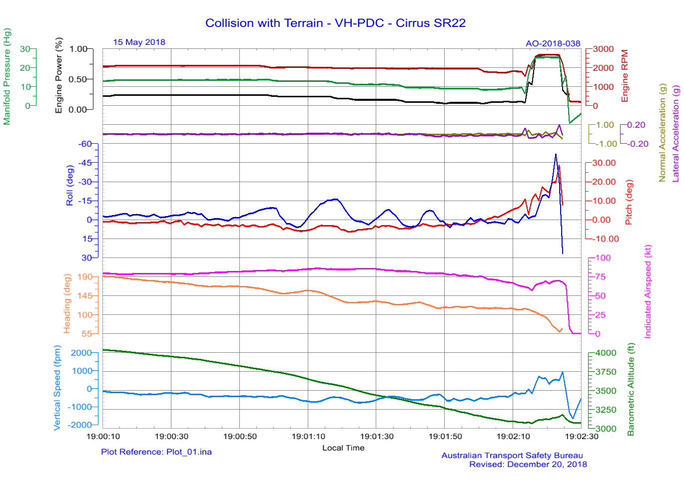
Figure 6: Recovered accident flight data

Figure 6: Recovered accident flight data

Source:  ATSB

The recovered flight data indicated that after touchdown, power was initially increased to about 45 per cent (19:02:15) and a slight left roll initiated. Power was then advanced to about 90 per cent (19:02:18) and the left roll developed to a peak value of -52° (19:02:23) with a pitch attitude of +20° (nose-up)[15] and airspeed varying from 56–69 kt.[16] The pitch attitude then increased to a peak value of +29° before lowering to +7° as the aircraft rolled right to a peak value of +27° at a height of about 100 ft above the runway (19:02:25).

The aircraft collided with the ground followed by the airport boundary fence and came to rest inverted during the period 19:02:26–30.[17] The final track at initial impact was about 60° left of the runway centreline. During the accident sequence, the rate of heading change to the left developed commensurate with the angle of left roll, and the recorded normal and lateral G‑accelerations[18] were minimal.[19]

Wreckage information

With the exception of the right rudder cable, no mechanical defect was found that could have prevented the normal operation of the aircraft. The right rudder cable was found attached to the rudder, but the forward end was found with a failure near the connection to the rudder pedals. The cable was removed from the wreckage for examination by the ATSB. A preliminary examination determined it did not fail from fatigue. The aircraft’s flight data demonstrated the rudder was operational during the accident sequence. On that basis, it was concluded that the rudder failure observed was a result of the impact, and no further examinations were conducted on the rudder cable assembly.

Survival factors

The aircraft was fitted with a composite roll cage within the fuselage structure to provide roll protection for the occupants. The front seats were each fitted with a four-point inflatable restraint system with an inertia reel lock. Despite coming to rest inverted after striking the ground at about 60–70 kt, the pilot and instructor reported that they found themselves uninjured, but could not open the doors with the aircraft inverted.[20] The inflatable restraints (air bag style system) did not activate, but this was considered likely to be due to the gradual level of deceleration.

The iBrace Survivor Questionnaire[21] was completed for the pilot and instructor with the following results:

  • The pilot was able to evacuate unassisted from the aircraft while it was filling with smoke by kicking out a window. He then pulled the instructor out of the burning wreckage after seeing her collapsed inside. He suffered from third-degree burns to 7 per cent of his body.
  • The instructor was unable to evacuate unassisted from the aircraft after she became disorientated in the dark, smoke filled environment, which led to a loss of consciousness. She suffered from first and second-degree burns and smoke inhalation injuries, which required her to be intubated.

Closed-circuit television footage identified an ambulance crossing the runway towards the accident site about 3 minutes after impact. In addition, an emergency medical service helicopter was located at the airport with the crew on duty at the time of the accident. They transported the pilot and instructor to Sydney for treatment.

Additional information

Spatial disorientation

The pilot reported that the aircraft pitched up when he applied power for the go-around and that he observed the runway lights disappear off to the right. He felt that the aircraft was in a roll while he was trying to focus his eyes on the attitude indicator as the instructor was directing him to level the wings. He commented that without enough right rudder the aircraft will ‘pull to the left’ [when applying additional power] and that it is normal to apply right rudder, but that ‘it was pitch black’.

There is a small village, Spring Hill, located upwind of runway 11, but the instructor reported that it was not large enough to produce an illuminated horizon below about 200 ft above ground level. She reported that on the night of the accident, at low level with the runway lights obscured, it was ‘pitch black’, and that [for a pilot looking outside] the environment would have been ‘totally disorientating’.[22]

Benson (1988; as cited in Gibb et al., 2011) defined spatial disorientation as:

The pilot fails to sense correctly the position, motion, or attitude of his [or her] aircraft or of himself [or herself] within the fixed coordinate system provided by the surface of the earth and the gravitational vertical.

The three sensory systems for determining orientation of the human body in space are the visual, vestibular,[23] and somatosensory[24] systems. Newman (2007) and others have reported that the visual system provides 80 per cent of the orientation information in normal conditions. However, in the absence of visual cues, orientation and motion information are divided between the vestibular and somatosensory systems. These systems can easily produce false information for a pilot due to local accelerations of the aircraft about the pitch, roll and yaw axes.

The vestibular system responds to head position and movement, which may lead to an incorrect perception of body motion if not supported by a visual reference. For example, an upward pitch (head backward) may be detected as a forward acceleration, and a roll as a lateral (sideways) acceleration. The somatosensory system detects local accelerations on the body, but if the pitching and rolling motions occur at close to +1G flight, such as during the accident sequence, the somatosensory system may not be able to resolve ambiguities generated by the vestibular system.

It was noted by Newman (2007) and Gibb et al. (2011) that spatial disorientation is likely an under‑reported phenomena in aviation. They suggested that this may be due to it resulting in one of two likely outcomes; either the pilot recovers the aircraft with no harm or damage done, and therefore does not perceive the need to report; or it results in a fatal accident and the investigation cannot verify from the evidence available that spatial disorientation contributed to the event.

Flight instruction

Instrument flying proficiency

The Civil Aviation Safety Authority’s (2007) Flight Instructor Manual: Aeroplane, chapter 18: Night Flying, states the following:

Before students undertake night solo circuit operations they must have received sufficient instrument flight training to enable them [to] carry out the following manoeuvres solely by reference to instruments: a) climb and climbing turns, b) straight and level flight and level turns, c) descent and descending turns, d) unusual attitude recovery full panel.

As the pilot already held a private instrument rating, the above training exercises were not required to be conducted as lead-in to his night flying training.

Demonstration

The Flight Instructor Manual stated that ‘airborne sequences must follow an acceptable method of teaching like: demonstrate, direct then monitor. However, the pilot acted as flying pilot for his first night flying training flight without a prior demonstration.[25] The instructor explained that there were several reasons for this as follows:

  • When the pilot first approached the instructor for his private instrument rating training, he was already a qualified pilot [private pilot licence] who owned his own aircraft and was capable of flying it competently. The instructor considered him an advanced student for the instrument training as he had already accumulated several hundred flying hours experience.
  • The instructor used the direct method to deliver the pilot’s instrument training. This was about 40 hours of dedicated instrument flying training.
  • At the time of the accident flight, the instructor and pilot had accumulated about 50 hours flying together without the need for the instructor to demonstrate a flying sequence or intervene to correct an improperly flown sequence. The pilot’s instrument flying training ensured he had accumulated sufficient minimum instrument flying prior to his first night flying training flight.
Benefit of demonstration

The benefit of demonstration as an instructional technique is that it permits the student to focus their attentional resources on key learning points for new sequences, without the diversion of those resources to managing the flight path. Studies have noted that observational experience, in addition to physical practice, can provide a more effective learning experience than physical practice alone.

In 2000, Shea et al. compared the performance of a physical practice group with a combined observation and physical practice group on a motor learning test. The physical practice group outperformed the combined practice group under the practice test conditions, but when the test conditions were varied from the practice conditions, the combined practice group ‘performed significantly better’ than the physical practice group.

Intervention

After the go-around was commenced, the instructor reported that the aircraft entered an unusual attitude. Both the instructor and pilot reported that the instructor was repeatedly directing the pilot to level the wings. The instructor commented that at the time, she was thinking ‘get that left wing up’, but directing ‘wings level’. At the time, her eyes were focused on the pilot’s attitude indicator[26] and she was expecting the pilot to recover the aircraft. However, the pilot had become spatially disorientated, which she was not aware of. It was only a matter of seconds between the instructor’s comprehension that the aircraft was not responding and the impact with the ground. The instructor considered that it ‘happened very fast’, and that as she was not in the habit of taking over the controls from the pilot, her natural reaction was to direct what was needed. The pilot also reported that it ‘happened very quickly’, with ‘no height to recover’.

The Cirrus SR22 is fitted with two single-handed side control yokes mounted beneath the instrument panel on the left and right side of the cockpit, and the instructor reported that it is not an easy aircraft for an instructor to take over control from a student. She commented that the single-handed yokes are sensitive in their response, which can lead to ‘fighting over the controls’ if the instructor attempts to follow-through on the controls[27] while a student is flying. Therefore, she was not following through on the controls during the touch-and-go sequence.

Previous similar accidents

Spatial disorientation

Spatial disorientation presents a danger to pilots as the resulting confusion can often lead to incorrect control inputs and resultant loss of aircraft control. Gibb and others (2010) state that spatial disorientation accidents have a fatality rate of about 90 per cent, indicating how compelling the misperceptions can be. A search of contributing safety factors in the ATSB aviation occurrence database revealed that of the investigated accidents where spatial disorientation was found to be a factor (about one per year), nearly all resulted in fatal injuries.

The United States National Transportation Safety Board’s database was searched for previous accidents involving spatial disorientation. A search of all aircraft categories returned 710 results. Cirrus SR20 and SR22 aircraft returned 18 results for spatial disorientation as a finding between 2003 and 2017, 13 of which were fatal accidents (four of the non-fatal accidents involved use of the Cirrus Airframe Parachute System for recovery). The conditions for all of the accidents were instrument meteorological or night, or combination of both. Of the 18 accidents for Cirrus aircraft, 10 were for instrument-rated pilots and four occurred during take-off.

The ATSB education booklet Avoidable Accidents No. 7, Visual flight at night accidents: What you can’t see can still hurt you (AR-2012-122) outlines a number of night-time accidents that have been a result of spatial disorientation due to dark night conditions.

Loss of control during go-around

A search of the ATSB database for previous SR22 accidents involving a loss of control during a go-around manoeuvre found one result of interest:[28]

  • During a touch-and-go training exercise, the aircraft veered off the runway to the left while under full power for take-off. The pilot reported that his attention may have been diverted to the flap control lever at the time (ATSB reference number 201006782).

The United States National Transportation Safety Board’s database was searched for previous similar accidents. The search criteria were Cirrus SR22, instructional flight, and accident. The search results were then filtered for loss of control events during an attempted go-around. The following results of interest were reviewed:

  • Report ERA12FA540: Loss of control in-flight. ‘During the final approach, witnesses saw the airplane drifting to the left while descending at a relatively high sink rate. Witnesses heard the power being adjusted, and, close to the ground, the engine went to high power. The airplane’s nose rose, and the airplane veered to the left. The airplane touched down left wing down off the runway in grass, heading about 40 degrees left of the runway centreline. It then entered woods, where it hit numerous trees and came to rest upside down and on fire…Examination of the wreckage revealed no pre-existing mechanical anomalies that would have precluded normal operation’.
  • Report ERA13CA222: Landing area overshoot. ‘According to the instructor, he and the student pilot were practicing short field landings. When the airplane was about 20 feet above the ground on approach to the runway, the airspeed suddenly decreased. The student pilot applied full engine power, the airplane yawed to the left, and the airplane impacted the ground before it reached the runway. The flight instructor reported no pre-impact mechanical malfunctions or failures with the airplane that would have precluded normal operation’.
  • Report NYC07CA010. ‘As the pilot of the SR-22 was performing a flare for landing, the airplane’s airspeed “became too slow,” and the pilot applied full power and announced “go-around.” The airplane veered left, and continued approximately 100 yards, before it struck a tree and came to rest upright. The pilot reported no mechanical anomalies with the airplane’.

__________

  1. The aircraft was fitted with the Cirrus Airframe Parachute System (CAPS), which is a ballistic parachute recovery system. When the pilot activates the CAPS system, a rocket in the aft fuselage ignites and dislodges the CAPS cover. The rocket then extracts a deployment bag containing the parachute from the aircraft.
  2. As advertised by the manufacturer - Heads Up Technologies.
  3. The nose-up pitch attitude on take-off and the first touch-and-go circuit was 7–9°. When the aircraft is trimmed for a low power and low airspeed approach, an increase in thrust over the tailplane will increase the down force produced by the tailplane, pitching the tailplane down and the nose up.
  4. An approximate stall speed of 73 kt was calculated. Conditions were: full flap, full fuel, two occupants, 20° pitchup, 52° roll, density altitude 2,600 ft and idle power. The use of high power would reduce the stall speed.
  5. The airport camera footage timings are about 30 seconds in advance of the aircraft recorded data for reasons undetermined.
  6. G load: the nominal value for acceleration. In flight, g load represent the combined effects of flight manoeuvring loads and turbulence and can have a positive or negative value.
  7. The peak variation in normal and lateral accelerations were +0.24 and -0.07 respectively (datum = 0.0).
  8. The aircraft doors open upwards and forwards relative to the cabin with the aircraft in the upright position.
  9. Davies J.M., Wallace W.A., Colton C.L. & Yoo K.I. (in press). Two aviation accident investigation questionnaires for passenger & crew survival factors & injuries. Aviation Medicine and Human Performance.
  10. The instructor reported that the township of Orange, to the north of the extended centreline for runway 29, provided more lighting than Spring Hill, but was partially masked by the surrounding terrain and would not have provided any significant light had that runway been used at the height at which this event occurred.
  11. The vestibular system consists of the semi-circular canals and otolith organs in the inner ear, which detect angular and linear accelerations of the head.
  12. The somatosensory system uses nerves to detect external forces on the body.
  13. The accident flight was the instructor and pilot’s first dedicated circuit flying training session together – the instructor was not involved in the pilot’s basic flying training.
  14. Although the aircraft was fitted with two MFDs, the primary flight display with the attitude indicator is only displayed on the left MFD, except in the case of a failure of that MFD, in which case the primary flight display will be displayed on the right MFD.
  15. For an instructor, ‘follow-through on the controls’ is the practice of holding the controls while the student is flying. This permits the instructor to feel the student’s control inputs and override incorrect control inputs to prevent the development of an unsafe situation.
  16. There were other results of loss of control during go-around manoeuvres with full power for the SR22, but these included strong gusting wind conditions as contributing factors.

Safety analysis

Introduction

During a night training flight, a go-around from runway 11 at Orange Airport, New South Wales was commenced. Shortly after, the Cirrus SR22 aircraft, registered VH-PDC, collided with the ground. The flight instructor and pilot received serious injuries and the aircraft was destroyed.

As mentioned above, the presence of a fractured rudder cable in the wreckage was not considered a contributing factor. This was because the rate of heading change during the accident sequence followed the angle of roll, rather than the application of power, and there was no significant lateral acceleration associated with the application of power.

The data logging card did not record pilot control inputs or movement of the autopilot servos. Therefore, it could not be determined if the reversal of the initial rolling and pitching motion was the result of the actions of the pilot, or flight instructor, or the aircraft’s electronic stability and protection system. However, the thresholds for activation of the aircraft’s pitch and roll protection were reached during the accident sequence, and the reversal of the pitch and roll were consistent with the operation of the system. While the system was designed to mitigate an unusual attitude from developing, the act of recovering from a high pitch angle at slow speed will inevitably result in a loss of height.

The final approach on the accident flight was steep at 500 ft. While this was corrected before the landing, it would have increased the pilot’s workload during the approach. Using this as a trigger to conduct a go‑around would have provided the pilot with the opportunity to set up for a more stable approach on the next circuit.

This analysis will examine the conduct of flight demonstrations, and the pilot experiencing spatial disorientation and the flight instructor’s awareness of such.

Flight demonstration

The pilot was undergoing his first night flying training flight for the addition of a night endorsement to his private instrument rating. The flight instructor had previously instructed the pilot for his instrument rating, and considered him an advanced student. His instrument flying training was delivered by the instructor using the instructional method of direct, without the need to demonstrate any sequence or intervene to correct an incorrectly flown sequence. Because of this earlier experience, the instructor elected to use the instructional method of direct without first demonstrating any of the key learning points for the night flying environment.

Night circuits involve a unique runway environment for assessing the approach path and landing, and require a unique procedure for combining visual and instrument flying sequences. The Civil Aviation Safety Authority’s flight instructor manual emphasised that the ‘acceptable delivery rate of new information to the student [pilot] needs to be combined with good demonstrations and adequate student practice’. Consistent with this guidance, best practice is to ensure that the student [pilot] is introduced to a new environment in a gradual way. The lack of demonstration for the pilot’s introduction to night flying likely increased the risk of the pilot not having an adequate opportunity to attend to, and absorb, the key learning points before attempting to practice the sequences as the pilot flying.

Spatial disorientation

The flight instructor reported that the pilot’s first night circuit was flown to a reasonable standard with the pilot responding to her direction. At the end of the second circuit, the aircraft bounced twice during the attempted touchdown and the pilot applied full power to perform a go-around. In response to the application of full power, the aircraft pitched nose-up and started to roll to the left. The pilot reported that he lost all external visual references as the runway lighting disappeared from view underneath the aircraft, and was attempting to focus his attention on the attitude indicator as the aircraft continued to pitch up and roll left.

The pitching and rolling motion of the aircraft, in addition to the pilot and instructor reports that the external environment was ‘pitch black’, were all consistent with the pilot experiencing spatial disorientation. The nose up pitching motion and left rolling motion were consistent with the natural response of the aircraft without corrective pilot control input.

Flight instructor awareness

During the accident sequence, the flight instructor repeatedly directed the pilot ‘wings level’, but her attention was focused on the primary flight display and she was not aware the pilot had become spatially disorientated. Therefore, she did not immediately intervene to recover control of the aircraft during the accident sequence, which only lasted about 7 seconds from the decision to go-around to initial impact.

Findings

From the evidence available, the following findings are made with respect to the spatial disorientation and collision with terrain involving Cirrus SR22, registered VH-PDC, at Orange Airport, New South Wales, on 15 May 2018. These findings should not be read as apportioning blame or liability to any particular organisation or individual.

Contributing factors

  • While attempting a go-around manoeuvre from an aborted touch-and-go, the pilot did not immediately transition his scan onto the attitude indicator and became spatially disorientated, which resulted in loss of control of the aircraft and collision with terrain.
  • The flight instructor was not aware the pilot had become spatially disorientated, which resulted in her providing direction rather than intervention during the loss of control.

Other factors that increased risk

  • Contrary to best practice, the flight instructor elected to direct the pilot for his first night flight without a demonstration. This decision was influenced by the pilots' experience, private instrument rating, and previous instructional method.

General details

Flight Instructor details

Licence details:Commercial Pilot Licence (Aeroplane), issued 11 February 2015
Endorsements:Manual Propeller Pitch Control; Retractable Undercarriage; Tail Wheel Undercarriage; Spinning; Aerobatics
Ratings:Multi Engine Aeroplane; Single Engine Aeroplane; Instrument; Night Visual Flight Rules; Flight Instructor
Medical certificate:Class 1, valid to 24 February 2019
Aeronautical experience:Approximately 4,200 hours
Last flight review:3 December 2017

Pilot details

Licence details:Private Pilot Licence (Aeroplane), issued 3 November 2016
Endorsements:Manual Propeller Pitch Control; Retractable Undercarriage
Ratings:Single Engine Aeroplane; Private Instrument
Medical certificate:Class 2, valid to September 2018
Aeronautical experience:Approximately 500 hours on Cirrus
Last flight review:11 March 2017

Aircraft details

Manufacturer and model:Cirrus Aircraft SR22
Year of manufacture:2016
Registration:VH-PDC
Operator:Intact Aviation Pty Ltd
Serial number:4328
Total Time In Service260.1 hours at last maintenance release issued 2 July 2017
Type of operation:Flying training – training dual
Persons on board:Crew – 2Passengers – nil
Injuries:Crew – 2 (serious)Passengers – nil
Damage:Destroyed

Sources and submissions

Sources of information

The sources of information during the investigation included the:

  • Cirrus Aircraft
  • Civil Aviation Safety Authority
  • flight instructor
  • Orange City Council
  • pilot
  • United States National Transportation Safety Board.

References

Civil Aviation Safety Authority 2007, Flight instructor manual: aeroplane, issue 2, CASA, Canberra.

Gibb R, Ercoline B & Scharff L 2011, ‘Spatial disorientation: decades of pilot fatalities’, Aviation, space, and environmental medicine, vol. 82, no. 7.

Newman DG 2007, An overview of spatial disorientation as a factor in aviation accidents and incidents, Australian Transport Safety Bureau, Canberra. Aviation research and analysis report – B2007/0063.

Shea C, Wright D, Wulf G & Whitacre C 2000, ‘Physical and observational practice afford unique learning opportunities’, Journal of motor behavior, vol. 32, pp. 27–36

Submissions

Under Part 4, Division 2 (Investigation Reports), Section 26 of the Transport Safety Investigation Act 2003 (the Act), the Australian Transport Safety Bureau (ATSB) may provide a draft report, on a confidential basis, to any person whom the ATSB considers appropriate. Section 26 (1) (a) of the Act allows a person receiving a draft report to make submissions to the ATSB about the draft report.

A draft of this report was provided to Cirrus Aircraft, Civil Aviation Safety Authority, flight instructor, pilot and United States National Transportation Safety Board.

The submissions from those parties were reviewed and where considered appropriate, the text of the draft report was amended accordingly.

Terminology used in this report

Occurrence: accident or incident.

Safety factor: an event or condition that increases safety risk. In other words, it is something that, if it occurred in the future, would increase the likelihood of an occurrence, and/or the severity of the adverse consequences associated with an occurrence. Safety factors include the occurrence events (e.g. engine failure, signal passed at danger, grounding), individual actions (e.g. errors and violations), local conditions, current risk controls and organisational influences.

Contributing factor: a safety factor that, had it not occurred or existed at the time of an occurrence, then either: (a) the occurrence would probably not have occurred; or (b) the adverse consequences associated with the occurrence would probably not have occurred or have been as serious, or (c) another contributing factor would probably not have occurred or existed.

Other factors that increased risk: a safety factor identified during an occurrence investigation, which did not meet the definition of contributing factor but was still considered to be important to communicate in an investigation report in the interests of improved transport safety.

Other findings: any finding, other than that associated with safety factors, considered important to include in an investigation report. Such findings may resolve ambiguity or controversy, describe possible scenarios or safety factors when firm safety factor findings were not able to be made, or note events or conditions which ‘saved the day’ or played an important role in reducing the risk associated with an occurrence.

Safety issue: a safety factor that (a) can reasonably be regarded as having the potential to adversely affect the safety of future operations, and (b) is a characteristic of an organisation or a system, rather than a characteristic of a specific individual, or characteristic of an operational environment at a specific point in time.

Safety action: the steps taken or proposed to be taken by a person, organisation or agency in response to a safety issue.

Purpose of safety investigations & publishing information

Purpose of safety investigations

The objective of a safety investigation is to enhance transport safety. This is done through: 

  • identifying safety issues and facilitating safety action to address those issues
  • providing information about occurrences and their associated safety factors to facilitate learning within the transport industry.

It is not a function of the ATSB to apportion blame or provide a means for determining liability. At the same time, an investigation report must include factual material of sufficient weight to support the analysis and findings. At all times the ATSB endeavours to balance the use of material that could imply adverse comment with the need to properly explain what happened, and why, in a fair and unbiased manner. The ATSB does not investigate for the purpose of taking administrative, regulatory or criminal action.

Terminology

An explanation of terminology used in ATSB investigation reports is available here. This includes terms such as occurrence, contributing factor, other factor that increased risk, and safety issue.

Publishing information

Released in accordance with section 25 of the Transport Safety Investigation Act 2003

Published by: Australian Transport Safety Bureau

© Commonwealth of Australia 2019

image_5.png

Ownership of intellectual property rights in this publication

Unless otherwise noted, copyright (and any other intellectual property rights, if any) in this report publication is owned by the Commonwealth of Australia.

Creative Commons licence

With the exception of the Coat of Arms, ATSB logo, and photos and graphics in which a third party holds copyright, this publication is licensed under a Creative Commons Attribution 3.0 Australia licence.

Creative Commons Attribution 3.0 Australia Licence is a standard form licence agreement that allows you to copy, distribute, transmit and adapt this publication provided that you attribute the work.

The ATSB’s preference is that you attribute this publication (and any material sourced from it) using the following wording: Source: Australian Transport Safety Bureau

Copyright in material obtained from other agencies, private individuals or organisations, belongs to those agencies, individuals or organisations. Where you wish to use their material, you will need to contact them directly.

Preliminary report

Report release date: 28/06/2018

This preliminary report details factual information established in the investigation’s early evidence collection phase and has been prepared to provide timely information to the industry and public. Preliminary reports contain no analysis or findings, which will be detailed in the investigation’s final report. The information contained in this preliminary report is released in accordance with section 25 of the Transport Safety Investigation Act 2003.

Sequence of events

On 15 May 2018, at 1903 Eastern Standard Time,[1] a Cirrus SR22 aircraft, registered VH‑PDC, collided with terrain at Orange Airport, New South Wales. The accident was a night training flight with one pilot (aircraft owner) and one instructor on board. The pilot and instructor were seriously injured and the aircraft destroyed.

The pilot had a private instrument rating and the accident flight was the pilot’s first training flight for a night endorsement.[2] The pilot performed a pre-flight inspection of the aircraft in a hangar under lights and then moved the aircraft out of the hangar onto the apron. After the instructor arrived, a pre-flight briefing was held in the hangar, which included the effects of the night environment on depth perception and the procedural differences from daytime flying.

The pilot and instructor boarded the aircraft and completed all the checklist items on the multi‑function display. The aircraft was taxied for a departure from runway 11 and the pilot activated the runway lighting while taxiing. In addition to the runway lighting, precision approach path indicator (PAPI) lighting was also available.[3]

One touch-and-go[4] circuit was completed to runway 11 without incident. On the second circuit, when at about 500 ft above ground level on approach to land, the pilot noted the PAPI was displaying four-white lights. In response, the pilot steepened the approach and then observed two‑white and two-red lights. When the runway surface came into view in the aircraft landing lights, the pilot flared for the landing. The aircraft bounced and the pilot elected to apply full power and go-around, rather than attempt to continue with the landing.

When full power was applied, with full flap selected, the aircraft pitched up. As the pilot was transitioning his scan onto the instruments, the instructor repeatedly directed him to maintain wings level. The pilot felt the aircraft was rolling to the left and the runway lights appeared to the right.[5] Shortly after, the aircraft collided with the ground and came to rest inverted (Figure 1).

Figure 1: Cirrus SR22 registered VH-PDC wreckage

Figure 1: Cirrus SR22 registered VH-PDC wreckage. Source: ATSB

Source: ATSB

The pilot exited the aircraft after kicking out a window, at which stage the wings were alight and a grass fire had started. He then assisted the instructor with exiting. While moving the instructor clear, the pilot heard a canister discharge from inside the wreckage and about 1 minute later he heard what sounded like the aircraft parachute pyrotechnic activate.[6] Emergency services located at the airport immediately responded to the accident.

Closed-circuit television footage

Closed-circuit television footage from Orange Airport showed the aircraft rolling left at a low height above runway 11 and impact the ground on the north-east side of runway 11 at 1903. A fire ensued about 5 seconds after impact and about 9 minutes after impact a pyrotechnic device activated.

Ongoing investigation

The investigation is continuing and will include the following:

  • interviews with the pilot, instructor and any witnesses (preliminary interview with pilot completed and a preliminary statement has been provided by the instructor)
  • examination of aircraft recorded data
  • examination of the aircraft flight controls.

_________
The information contained in this preliminary report is released in accordance with section 25 of the Transport Safety Investigation Act 2003 and is derived from the initial investigation of the occurrence. Readers are cautioned that new evidence will become available as the investigation progresses that will enhance the ATSB's understanding of the accident as outlined in this preliminary report. As such, no analysis or findings are included in this update.

Purpose of safety investigations

The objective of a safety investigation is to enhance transport safety. This is done through:

  • identifying safety issues and facilitating safety action to address those issues
  • providing information about occurrences and their associated safety factors to facilitate learning within the transport industry.

It is not a function of the ATSB to apportion blame or provide a means for determining liability. At the same time, an investigation report must include factual material of sufficient weight to support the analysis and findings. At all times the ATSB endeavours to balance the use of material that could imply adverse comment with the need to properly explain what happened, and why, in a fair and unbiased manner. The ATSB does not investigate for the purpose of taking administrative, regulatory or criminal action.

Terminology

An explanation of terminology used in ATSB investigation reports is available here. This includes terms such as occurrence, contributing factor, other factor that increased risk, and safety issue.

Publishing information 

Released in accordance with section 25 of the Transport Safety Investigation Act 2003

Published by: Australian Transport Safety Bureau

© Commonwealth of Australia 2018

image_5.png

Ownership of intellectual property rights in this publication

Unless otherwise noted, copyright (and any other intellectual property rights, if any) in this report publication is owned by the Commonwealth of Australia.

Creative Commons licence

With the exception of the Coat of Arms, ATSB logo, and photos and graphics in which a third party holds copyright, this publication is licensed under a Creative Commons Attribution 3.0 Australia licence.

Creative Commons Attribution 3.0 Australia Licence is a standard form licence agreement that allows you to copy, distribute, transmit and adapt this publication provided that you attribute the work.

The ATSB’s preference is that you attribute this publication (and any material sourced from it) using the following wording: Source: Australian Transport Safety Bureau

Copyright in material obtained from other agencies, private individuals or organisations, belongs to those agencies, individuals or organisations. Where you wish to use their material, you will need to contact them directly.

__________

  1. Eastern Standard Time (EST): Coordinated Universal Time (UTC) + 10 hours.
  2. A pilot who has a private instrument rating is authorised to operate at night under the instrument flight rules only if that pilot holds a night private instrument endorsement.
  3. PAPI is a visual aid that provides pilots with guidance on acquiring and maintaining the correct vertical approach path to a runway. The system consists of four side-by-side lights positioned to the side of the runway. At Orange, the lights are on the left side of runway 11 and runway 29. When the aircraft is on the desired approach path (3°), two red and two white lights will be visible. If more than two red lights appear, the aircraft is below the flight path and if more than two white lights are visible, the aircraft is above the flight path.
  4. A procedure whereby an aircraft lands and takes off without coming to a stop.
  5. The Cirrus SR22 aircraft’s propeller rotates clockwise, as viewed from the pilot’s seat. Therefore, an increase in power will increase the engine torque reaction and propeller slipstream. Without pilot input, the natural response from the aircraft is to roll and yaw to the left.
  6. The aircraft was fitted with the Cirrus Airframe Parachute System (CAPS), which is a ballistic parachute recovery system. When the pilot activates the CAPS system, a rocket in the aft fuselage ignites and dislodges the CAPS cover. The rocket then extracts a deployment bag containing the parachute from the aircraft.

Occurrence summary

Investigation number AO-2018-038
Occurrence date 15/05/2018
Location Orange Airport
State New South Wales
Report release date 06/06/2019
Report status Final
Investigation level Defined
Investigation type Occurrence Investigation
Investigation status Completed
Mode of transport Aviation
Aviation occurrence category Loss of control
Occurrence class Accident
Highest injury level Serious

Aircraft details

Manufacturer Cirrus Design Corporation
Model SR22
Registration VH-PDC
Serial number 4328
Aircraft operator Intact Aviation
Sector Piston
Operation type Flying Training
Departure point Orange Airport, New South Wales
Destination Orange Airport, New South Wales
Damage Destroyed

Loss of control and collision with terrain involving Eurocopter AS350BA, VH-BAA, Hobart Airport, Tasmania, on 7 November 2017

Final report

Report release date: 22/07/2020

Safety summary

What happened

On 7 November 2017, a chief flying instructor (CFI) and pilot under instruction (PUI) were flying a Eurocopter AS350BA Squirrel, registered VH-BAA. They were conducting practice emergencies under visual flight rules at Hobart Airport, Tasmania. During hydraulic system failure practice, control of the helicopter was lost and the aircraft collided with terrain. The CFI was fatally injured and the PUI was seriously injured.

What the ATSB found

Flight manual emergency procedures stipulate that in order to maintain control following a hydraulic system failure (or simulated failure), a shallow approach should be made into wind and the helicopter should not enter a hover. On this occasion, the aircraft approached crosswind and came to a high hover without hydraulic assistance. Consequently, the helicopter was rendered uncontrollable. A delay in restoration of the hydraulic system prevented the crew from regaining control before collision with terrain.

The ATSB also identified that:

  • An intermittent fault in the hydraulic cut-off switch may have delayed restoration of flight control hydraulic pressure.
  • A pre‑flight brief was not conducted between the CFI and PUI which may have led to confusion over aircraft control and delayed restoration of the hydraulic system.

Due to a lack of available information, the influence, if any, of these two factors on the accident sequence could not be determined.

What's been done as a result

Following this accident, the operator:

  • employed a trained and regulator-approved safety manager
  • updated the training school operations manual with stricter controls on performing AS350 sequences as per the flight manual requirements
  • installed an electronic system for tracking competencies and currencies.

The operator has also separated key roles of chief executive officer, chief flight instructor and the head of flight operations, which were previously conducted solely by the chief flight instructor.

Safety message

Compliance with the AS350 flight manual requirements following a real or simulated hydraulic failure ensures that the helicopter remains controllable during all phases of flight.

As this, and many other similar accidents illustrate, hovering an AS350 without hydraulic assistance can lead to a rapid, catastrophic loss of control even for highly experienced pilots. The Royal Australian Air Force found in evaluation of the AS350, while hovering without hydraulics, that the AS350 is subject to random perturbations, and reduction in control authority. Additionally the AS350 flight manual notes that without hydraulics the helicopter is subject to rapid changes in control direction and force.

In a training context, the rapid development of this accident, reinforces the need for a clear understanding and coordination between instructor and student when conducting hazardous activities such as simulated system failures.

Summary video


The occurrence

What happened

On 6 November 2017, a commercial helicopter pilot commenced a 2‑day AS350 helicopter endorsement as a pilot under instruction (PUI). The first day was spent with an instructor covering aircraft systems, and pre‑flight inspection. The PUI and instructor also conducted a 1.1-hour flight that afternoon covering the initial flying components of the endorsement.

On 7 November 2017, the PUI studied the aircraft’s electrical system, and theory on handling of in-flight emergencies, including hydraulic system emergencies, with the same instructor. Following the classroom session, the PUI conducted an inspection of the aircraft under the supervision of the instructor.

Flight records showed that at 1002 Eastern Daylight‑saving Time,[1] the PUI and instructor commenced a training flight of 1.2 hours covering pinnacle approaches and confined areas, followed by run-on landings.[2] The PUI’s next planned flight was with the chief flying instructor (CFI) at 1500 for the conduct of emergency sequences. The CFI was unable to depart at the pre‑arranged time as he was attending to business matters. The PUI reported that he also took the opportunity to catch up on his own business needs during the delay. The actual takeoff was delayed by 1 hour and 22 minutes.

The instructor advised the ATSB that, prior to the accident flight, the CFI conducted a brief handover with him to ascertain the standard of the PUI’s flying and the sequences briefed. At the aircraft, the PUI explained his requirement for a low-level approval and type endorsement with the CFI however, no pre‑flight brief was conducted.

The PUI and CFI boarded the aircraft and began the flight at 1622. Pre-flight checks included testing of the hydraulic system and switches with no apparent faults identified. The PUI recalled that following the low-level phase of the training flight, the CFI demonstrated some upper air emergencies and had the PUI perform them. After satisfactory completion, they flew back to Hobart Airport for a continuation of practice emergencies.

The PUI recalled that upon joining the circuit at left base for approach to area X-Ray parallel to runway 12 (Figure 1),[3] the CFI announced a simulated hydraulic failure and activated the hydraulic test (HYD TEST) switch. As expected, a warning light and horn sounded. The PUI slowed from 90 kt to below 60 kt, consistent with the flight manual profile for hydraulic failure (see the sections titled Hydraulic failure training and Hydraulic system). The PUI then activated the hydraulic cut-off (HYD CUTOFF) switch. Following that, it is highly likely that the HYD TEST switch was released, though it is not known specifically when that occurred.

The PUI was to fly a run-on landing at around 10 kt without hydraulic assistance as per the requirements of the flight manual procedure. The PUI said he was comfortable to do so knowing the CFI was there to step in if anything were to go wrong. The PUI had very little further recollection, beyond the initiation of the event.

Table 1 and Figure 1 show the progression of the helicopter through the accident sequence. Paths, angles and rates are inferred from CCTV footage, air traffic control (ATC) data, and airport photographs. Due to limitations in the data available, these are approximate values only.

Table 1: Accident sequence from CCTV

#SecondsAircraft behaviour
10Heading about 120°. VH-BAA enters frame. Travelling around 20 kt.
212Variations in pitch and yaw as VH-BAA slows to about 11 kt. Approach flattens, helicopter begins to yaw left.
318Change of heading to about 040° after yaw to left. Comes to hover in tail wind, slowly drifting.
421The aircraft climbs, pitches forward, crossing the runway, and continues to yaw left to a heading of about 300°. Yaw continues, aircraft turns left and pitches further forward to about 50° with left roll developing. Accelerates to over 20 kt ground speed.
528Heading about 240°. Slides outwards in left turn. Pitch down now around 45°, roll around 50°.
630Heading about 120°. Pitch down about 40°, roll increases to about 80°, helicopter impacts terrain.

Figure 1: Approximate path of VH-BAA

Figure 1: Approximate path of VH-BAA. Source: Hobart Airport, annotated by the ATSB

Source: Hobart Airport, annotated by the ATSB

At the end of the observed flightpath, the front left side of the cabin impacted the ground first. The CFI, seated on the left, was fatally injured, and the PUI in the right seat was seriously injured. The helicopter was destroyed.

  1. Eastern Daylightsaving Time (EDT): Coordinated Universal Time (UTC) + 11 hours.
  2. Run-on landing: Touching down with forward speed with the skids aligned with the direction of travel of the helicopter, and slowing to a full stop while maintaining constant contact with the ground.
  3. Runway number: the number represents the magnetic heading of the runway in ten degree increments.

Context

Personnel

Chief flight instructor

The chief flight instructor (CFI) had 30 years of experience flying helicopters and had accumulated 14,200 hours of aeronautical experience. His time on type for the AS350 was over 1,000 hours. He held an Air Transport Pilot License (Helicopter) and an authority to examine pilots for issuance of licences and endorsements. He had accumulated 45.3 hours flight in the previous 28 days.

The CFI was medically fit, qualified for the flight, and had demonstrated proficiency through flight checks in:

  • Flight instruction on 3 August 2017
  • Single Engine Helicopters on 30 June 2016
  • Low level flight on 31 March 2016.
Instructor

The instructor was an experienced helicopter pilot with 4,000 hours’ total aeronautical experience and 1,000 hours of AS350 experience. He had previously flown with the pilot under instruction (PUI) while working for a different operator. The PUI sought out this instructor to conduct his endorsement.

Pilot under instruction

The PUI was a commercial helicopter pilot with over 1,200 hours of rotary wing experience and he was medically fit for the flight. The PUI was also managing director of a local helicopter company. The endorsement was associated with the company’s introduction of AS350 helicopters to their fleet.

Organisational and management information

The operator had been in business for 26 years and established in Tasmania at Hobart International Airport for 17 years. They specialised in charter, aerial work, and flight training operations.

The CFI was also the owner of the business, head of flight operations, chief executive officer, and undertook operational flying.

Flight endorsement training

General information

The Civil Aviation Safety Authority, through Civil Aviation Advisory Publication 5.14‑2(0) Flight Instructor Training (Aeroplane), established the need for two briefings prior to flight: a classroom brief and a pre-flight brief. These two forms of briefing prepare students for learning and performing complex sequences. A long brief in the classroom links theoretical knowledge of emergencies to practical application of those principals in the aircraft. The pre-flight brief establishes procedures and management of the aircraft between the crew. This format was not applied for the accident flight. The first instructor conducted the classroom brief, but there was no pre-flight brief between the CFI and PUI.

Hydraulic failure training

Training for loss of hydraulics in the AS350 required adherence to instructions in two rotorcraft flight manual (RFM) sections: Supplement 7 for the training procedure itself, and Section 3 for emergency procedures for management of the aircraft without hydraulics.

Supplement 7 training procedure

Supplement 7 of the AS350 RFM was incorporated in 2003; it carried specific instructions for hydraulic failure training. The sequence was divided into two distinct phases, and the hydraulic cut-off (HYD CUTOFF) switch and hydraulic test (HYD TEST) switch would not be engaged at the same time. This prevented depletion of tail rotor hydraulic pressure accumulators (not fitted in VH‑BAA) and ensured only one switch would be required to restore hydraulics at any time. Figure 2 illustrates the two phases of the procedure.

Figure 2: AS350 Rotorcraft flight manual hydraulic failure training procedure

Figure 2: AS350 Rotorcraft flight manual hydraulic failure training procedure.
Source: ATSB. Flow chart derived from AS350 Rotorcraft Flight Manual

Source: ATSB. Flow chart derived from AS350 Rotorcraft Flight Manual

Incorrect sequence taught during endorsement

The instructor and the PUI advised that the flight school taught a different version of the hydraulic failure training procedure during the endorsement and used it during the accident flight.

The procedure used had the student activate the HYD CUTOFF switch before the HYD TEST switch was released. This was a commonly‑used procedure before the release of Supplement 7. An investigation into a similar accident in Canada (A13Q0021) related that flight instructors found this sequence accurately simulated a hydraulic failure. Figure 3 illustrates the procedure.

Figure 3: Hydraulic failure training procedure as taught

Figure 3: Hydraulic failure training procedure as taught.
Source: ATSB. Flow chart derived from accounts of procedure used by flight school

Source: ATSB. Flow chart derived from accounts of procedure used by flight school

VH-BAA was not fitted with a yaw load compensator. Using this procedure on an AS350 equipped with a yaw load compensator will cause total loss of tail rotor control hydraulic assistance.

Section 3 hydraulic failure emergency procedure

For completion of the transition to landing referred to in phase 2, the hydraulic failure emergency procedure from Section 3 of the RFM was to be applied. It stated:

Keep the aircraft to a more or less level attitude. Avoid abrupt manoeuvres.

The RFM also carried the following caution:

DO NOT ATTEMPT TO CARRY OUT HOVER FLIGHT OR ANY LOW SPEED MANEUVER. THE INTENSITY AND DIRECTION OF THE CONTROL FEEDBACK FORCES WILL CHANGE RAPIDLY. THIS WILL RESULT IN EXCESSIVE PILOT WORKLOAD. POOR AIRCRAFT CONTROL. AND POSSBILE LOSS OF CONTROL.

RFM Instructions for approach and landing were:

Over a clear and flat area, make a flat final approach, nose into wind.

Perform a no-hover/slow run-on landing around 10 knots.

Do not hover or taxi without hydraulic pressure assistance.

Helicopter details

General information

The Eurocopter AS350BA,[4] was manufactured in France in 1987 (serial number 2015). It was first registered in Australia on 4 April 2000 and at the time of the accident, had accumulated 5,612 hours total time in service. It was previously registered as VH-RLU and the registration mark was changed to VH-BAA by its current owner on 20 March 2007.

VH-BAA had seating for a pilot and five passengers and was certified for day and night charter operations under the night visual flight rules. The helicopter was powered by one Turbomeca Arriel 1B turboshaft engine.

A review of Maintenance Release entries for maintenance due, showed that a 6-month inspection was required on 7 October 2017, with an over-run tolerance of 60 hours or 18 days. With the tolerance applied, the maintenance would fall due on 25 October 2017. The maintenance related to periodic greasing of the main rotor blade retaining pins.

At the time of the accident, the maintenance had not been certified on the maintenance release as complete and was overdue. No record was found in the aircraft logbook that the maintenance had been completed. While it is a pilot responsibility to ensure that a flight does not commence unless all maintenance has been completed, it is highly unlikely that the non-lubrication of the main rotor blade pins contributed to the accident.

The operator reported that VH-BAA was on temporary hire for the purposes of the endorsement training. Between 5 November and 7 November, the helicopter was operated for about 2.5 hours in the training role. Neither the initial instructor nor the PUI reported problems with the performance of the helicopter or its operation.

Hydraulic system

The aircraft was equipped with a single hydraulic system, energised by a belt-driven hydraulic pump. The hydraulic pump was regulated to provide a constant pressure of 40 bar to four flight control servo actuators. A red warning light will light at hydraulic system pressures of less than 30 bar.

There were three Dunlop servo actuators for control of the main rotor and one Dunlop servo actuator for control of the tail rotor (Figure 4). With hydraulics operating, the input force required to move the rotor blades, at the cyclic,[5] is less than or equal to 0.3 kgf. For that cyclic input, at 40 bar, the system provides an output of 183.5 kgf.

Because the aircraft exhibits increasing control loads without hydraulics at high speed, and control may be lost without hydraulics in the hover, back-up accumulators are available in the hydraulic system. These accumulators store hydraulic pressure and deliver it to the servo actuators in the event of a hydraulic failure. The accumulators carry enough stored pressure for the pilot to establish the aircraft at the safety speed from cruise or from a high hover to a landing. A safety speed of 40-60 kt was stipulated in the emergency procedures section of the rotorcraft flight manual (RFM).

Figure 4: AS350 servo locations

Figure 4: AS350 servo locations.
Source: Airbus Helicopters

Source: Airbus Helicopters

A yaw load compensator was fitted to later iterations of the aircraft in order to overcome excessive forces in yaw control in the absence of hydraulic assistance. VH-BAA was not fitted with a yaw load compensator and did not have an accumulator on the yaw control. In the AS350BA, in the absence of hydraulic assistance, yaw control loads are felt directly and immediately.

Hydraulic system switches

The hydraulic system is managed via two switches. The guarded, console-mounted push-button HYD TEST switch, and the recessed, collective-mounted[6] HYD CUTOFF switch (Figure 5).

The HYD TEST switch exists to test the accumulators for the main rotor servo actuators before flight. The HYD TEST switch is OFF (out) in normal operation. Pressing the HYD TEST switch to TEST (in) creates a bypass in the hydraulic distribution block, routing pressurised fluid from the pump directly to the reservoir. This leaves the back-up accumulators to supply pressure to the main rotor servo actuators.

The HYD CUTOFF switch is ON (out) in normal operation. Pressing the HYD CUTOFF switch OFF (in) bypasses the servos by connecting the pressure inlet and return outlet in each one. The effect is to depressurise the servos and the back-up accumulators of the main rotor servo actuators. It is used in the event of an in‑flight emergency, once the safety speed of 40-60 kt has been established, to ensure that residual accumulator pressure causes no asymmetry in forces across the flight controls.

In emergency procedure training, the HYD TEST switch is used to induce hydraulic failure in flight and the HYD CUTOFF switch is used to conduct hydraulic off landings. If either switch is in, the system will not provide hydraulic pressure to the controls. As previously detailed in the section titled Hydraulic failure training, they should not be activated together in the AS350BA, so hydraulics can be restored with one switch.

Figure 5: HYD TEST switch and HYD CUTOFF switch locations

Figure 5: HYD TEST switch and HYD CUTOFF switch locations.
Source: Airbus Helicopters

Source: Airbus Helicopters

Main rotor system

The AS350 was fitted with a starflex hub (Figure 6). This design replaced hinges with elastomeric (rubber type) bearings. Without hydraulic assistance, the pilot must exert significant effort to push or pull the flight controls to deform the elastomeric bearings, change the pitch of the blades, and control the helicopter.

Figure 6: AS350 main rotor pitch change mechanism

Figure 6: AS350 main rotor pitch change mechanism.
Source: Airbus Helicopters

Source: Airbus Helicopters

The RFM states in section 3.2 that the expected control input forces without hydraulic pressure are:

  • Left-hand cyclic load 4 to 7 kgf
  • Forward cyclic load 2 to 4 kgf
  • Collective 20 kgf.

The RFM states in section 7.7 that the maximum forces a pilot should have to exert are:

  • Lateral cyclic 15.3 kgf
  • Longitudinal cyclic 17.3 kgf
  • Collective forces were not stated.
Tail rotor system

The AS350 tail rotor is built on one continuous composite spar (Figure 7). Without hydraulic assistance, the pilot must push the pedals and twist the spar to change the pitch of the tail rotor blades. While helicopter weight and speed affect pedal force, the Royal Australian Air Force (RAAF) Aircraft Research and Development Unit (ARDU) (see section titled Research) found that a tail rotor pitch change requires a force of up to 50 kgf. Airbus Helicopters advised they were able to demonstrate significantly lower required forces in flight tests while observing flight manual limitations.

Figure 7: AS350 Tail rotor

Figure 7: AS350 Tail rotor.
Source: Airbus Helicopters

Source: Airbus Helicopters

Automatic pilot

The aircraft was fitted with a two-axis automatic pilot system. The installation included two servos in line with the cyclic control’s pitch and roll control rods. The optional collective-to-yaw linkage, that can accompany this equipment, was not a part of this installation. The automatic pilot system was not a component of the endorsement, nor was it used during the endorsement. When the automatic pilot is disengaged, the servos of the automatic pilot system act in the same way as a push/pull rod. There was no evidence to indicate that the automatic pilot system was a factor in the occurrence.

Site and wreckage inspection

Aerodrome information

Hobart Airport is on the south-east coast of Tasmania and has a single north‑west/south‑east runway (Figure 8). Helicopter training area X-Ray was used on the day of the accident.

Area X-Ray was on the western side of, and 60m outside of, the runway. It was under the control of air traffic control (ATC), who provided clearances for all aircraft movements on and around the airport. A clearance was required for helicopters to overfly active taxiways and cross the runway.

Figure 8: Helicopter training area X-ray at Hobart International Airport

Figure 8: Helicopter training area X-ray at Hobart International Airport.
Source: Google earth, annotated by the ATSB

Source: Google earth, annotated by the ATSB

Site inspection

As the accident closed the only runway, Tasmania Police assisted the ATSB by documenting the site prior to the arrival of the on‑site investigators. This allowed the wreckage to be removed, and the airport to be reopened, without jeopardising important physical evidence such as ground contact marks. ATSB investigators examined the wreckage in a secure location nearby.

There was evidence that the engine was running for a period of time after the helicopter impacted with terrain, as indicated by burnt grass in the area of the engine exhaust, though there was no fire on site. Figure 9 shows the aircraft before removal.

Figure 9: Accident site image

Figure 9: Accident site image.
Source: Tasmania Police

Source: Tasmania Police

Survivability

Immediately after the accident, ATC activated the emergency response and closed the runway. The aviation rescue and firefighting services (ARFF) stationed at the airport responded immediately to the event, reaching the accident site in 1 minute 40 seconds. The ARFF recovered the CFI from the left seat and assisted the PUI from the right seat.

Damage was indicative of significant impact on the front left side. The flexible steel legs of the skid gear, four-point harnesses, crash-resistant seats and light alloy frame of the cabin floor, all offer protection to occupants during accidents if the helicopter contacts the ground in a level attitude. The polycarbonate construction of the cabin offers very little protection to occupants if the collision involves contact with the canopy.

Investigation of previous AS350 hydraulic failure accidents identified that on initiation of the loss of control event the aircraft often rolled to the left, and initial impact with ground was on the left-hand side. Consequently, the left seat occupant is likely to experience the highest impact forces during a collision. In this accident, the helicopter impacted the ground nose down while rolling to the left. As a result, there was significant disruption to the survivable space on the left side of the helicopter’s cabin.

Both pilots were wearing seatbelts with upper torso restraints, and the seatbelts and seats held during the accident sequence. This kept the right-seat pilot within a disrupted but liveable space within the cabin, contributing to his survival.

Wreckage inspection

The aircraft was inspected at a facility in Hobart.

Engine controls were found connected and secured with all attaching hardware present. The engine oil system was inspected, the oil filter, chip detector and oil were free from debris and discoloration. Fuel was tested for presence of water with no positive indication. The fuel had a clear appearance, the fuel filter was clean, and the bypass indicator was indicating normal operation.

The main rotor transmission had clean oil, the casing was intact, and the chip detector was free of debris. The tail rotor gearbox rotated freely with no binding, and the chip detector and gearbox oil was free of debris. The oil quantity was at the correct level.

Flight control linkages to the main rotor and tail rotor were connected, and securing hardware was in place. The hose supplying the tail rotor servo with pressure was found fractured; detailed examination concluded that was a result of impact damage.

The hydraulic system lines were mounted and connected correctly, and the hydraulic pump and drive belt were intact. The hydraulic fluid had a clear appearance, and the oil, chip-detector and filter were free of debris.

The back-up accumulators fitted to main rotor servos were checked for nitrogen charge and found to be serviceable. All hydraulic system shutoff valves (main and servo-mounted) were present and in place, with the wiring connected. Servo actuators were securely mounted with all electrical plugs and control rods securely in place.

Hydraulic system configuration

The HYD CUTOFF switch and the HYD TEST switch were found in the correct position for restoration of hydraulic pressure at the time of impact (Figure 10). It is possible that one or both switches moved during the impact sequence. The HYD TEST switch unit was found outside of the aircraft, in the off (normal operation) position.

Figure 10: HYD CUTOFF switch and control console as found

Figure 10: HYD CUTOFF switch and control console as found.
Source: ATSB

Source: ATSB

No pre-existing defects were identified. All damage noted was consistent with impact forces during the accident sequence.

The following items were collected for further assessment:

  • Pilot’s collective lever HYD CUTOFF switch
  • HYD TEST switch
  • Caution and Warning panel.
Hydraulic cut-off switch examination

The HYD CUTOFF switch is an ‘on condition’[7] component which is tested during pre-take-off checks, prior to every flight. Neither the initial instructor nor the PUI reported any anomaly with the switch prior to the accident flight.

Laboratory examination and comparative analysis of the HYD CUTOFF switch from VH-BAA was conducted with a new switch. They found that the switch fitted to VH-BAA at the time of the accident was susceptible to intermittent operation. The switch had a level of wear, corrosion, contamination and internal damage (Figure 11). Consequently, the mechanical latching and unlatching which cycled the internal contacts to ON or OFF could stick, and require additional effort to latch or unlatch.

Therefore, it was possible to action the HYD CUTOFF switch without restoring hydraulics, inducing a genuine emergency. The system’s normal 3-second activation period could delay diagnosis of a fault.

Additionally, Part 4.3 of section 7.7 of the RFM describes abnormal operations of the hydraulic system. It discusses the possibility that the switch may fail to dump hydraulic pressure from the accumulators in the event of an emergency.

The HYD CUTOFF switch may not be effective in opening all the electro-valves, and dumping all the pressure in the accumulators simultaneously…if the hydraulic cut-off switch is rendered ineffective due to the loss of electrical power, broken wires, or a faulty switch.

The manual made no comment on the opposite case of the switch failing while restoring hydraulics after hydraulic failure training.

It could not be determined if the intermittent operation was due in part to impact‑induced damage.

Figure 11: Corrosion, contamination, and wear in VH-BAA switch

Figure 11: Corrosion, contamination, and wear in VH-BAA switch.
Source: ATSB

Source: ATSB

Hydraulic warning system light bulb analysis

When the hydraulic system is inoperative, two incandescent bulbs light the red HYD warning light (Figure 12). Both of these bulbs were inspected for impact damage (Figure 13). The left bulb was intact and the right bulb exhibited pole whip damage (Carver, 1987). The pole whip created a brittle fracture between the terminal and the support post. There was some observed filament sag, which is consistent with an aged bulb exposed to high-impact forces. If the bulbs were illuminated at impact, provided the impact forces were sufficient, it is likely that the filaments would show evidence of stretch-type deformation damage. Therefore, it is considered probable that the HYD warning light was not illuminated at the time of impact.

Figure 12: VH-BAA Warning – Caution – Advisory Panel

Figure 12: VH-BAA Warning – Caution – Advisory Panel.
Source: ATSB

Source: ATSB

Figure 13: HYD. Warning Light bulbs

Figure 13: HYD. Warning Light bulbs.
Source: ATSB

Source: ATSB

Meteorological information

The automated weather information service[8] for Hobart Airport at the time of the accident on 7 November 2017 recorded the following conditions:

  • wind from 200°, minimum 15 kt maximum 25 kt
  • visibility greater than 10 km
  • cloud scattered[9] at 5,000 ft.
  • temperature 15° C
  • barometric pressure (QNH) 1019 hPa.

Recorded information

The aircraft did not carry any recording devices, nor was it required to.

Closed circuit television

Closed circuit television (CCTV) from the regular public transport apron of the Hobart Airport captured VH-BAA during approach, loss of control and impact. Figure 14 shows the point of view from the apron CCTV.

Figure 14: Apron CCTV point of view

Figure 14: Apron CCTV point of view.
Source: Hobart Airport, Google Earth, annotated by the ATSB

Source: Hobart Airport, Google Earth, annotated by the ATSB

Related occurrences

The ATSB reviewed 34 investigations of accidents involving AS350 series helicopter’s hydraulic systems worldwide. Figure 15 collates the data from ten of the accidents that occurred prior to the accident in VH-BAA, involving simulated hydraulic failure during flight training. It indicates that loss of control accidents during training do happen to highly experienced pilots. Refer to Appendix A for a synopsis of the reports and the Transport Safety Board of Canada’s report A05F0025 for a list of AS350 loss of control events.

Figure 15: Overview of related hydraulic failure training accidents.

Figure 15: Overview of related hydraulic failure training accidents.
Source: ATSB

Source: ATSB

Reports of unmovable controls have been a feature of a number of accidents following commanded/uncommanded hydraulic failures in AS350 helicopters. First-hand accounts relate that, as well as the rapid and intense changes in direction and magnitude of control forces described in the flight manual, the controls can become immobile.

The manufacturer is clear on avoidance of loss of control, yet the concern of unmovable controls, which is still reported in contemporary production models of the AS350 (see AAIB report EW/C2017/05/01 page 5), is not accepted by the manufacturer. Airbus Helicopters contends that pilots are surprised by the forces required and that prevents pilots from applying sufficient force to the flight controls.

Research

AS350BA controllability research and recommendations

In 1997, the RAAF ARDU conducted an evaluation of the handling characteristics of the AS350BA, in flight without hydraulic assistance.

ARDU found lateral forces with a 30 kt wind from 30° to the front right (a 15 kt crosswind component) caused lateral cyclic forces to vary continuously and ‘satisfactory lateral control could not be achieved’.

The forces required at the controls without hydraulics recorded during that evaluation were:

  • longitudinal cyclic 14.8 kgf forwards at 1,700 kg all up weight while established in a hover
  • lateral cyclic 6.8 kgf with a crosswind component of 15 kt
  • collective (lifting) 16.2 kgf at 1,950 kg all up weight into wind at 15 kt.

Furthermore, ARDU found that at low speed with hydraulics out, pedal authority was reduced by up to 27 per cent, and that passage through free play in the pedals was required to effect a change in heading. These conditions made control difficult to retain and harder to recover. Right pedal force of 50 kgf was required to maintain a heading into wind at 15 kt.

The ARDU report concluded that with hydraulics out:

  • reduced authority, free play, and excessive control forces in primary flight controls were unacceptable
  • controllability below 15 kt airspeed was not reliable, and hover flight could lead to loss of control.

Following the evaluation, ARDU recommended that when conducting hydraulic failure training:

  • use only one hydraulic switch at a time to simulate failure of the hydraulic system
  • maintain over 15 kt during the run-on landing
  • do not use over 30° angle of bank
  • conduct run-on landings into wind.
     
  1. AS350 Squirrel: The AS350 Squirrel was originally designed and manufactured by Aérospatiale in 1975, which became Eurocopter through merger in 1992. Eurocopter was purchased and became Airbus Helicopters in 2014. At the time of writing, the AS350 was manufactured as the H125.
  2. Cyclic: a primary helicopter flight control that is similar to an aircraft control column. Cyclic input tilts the main rotor disc, varying the attitude of the helicopter and hence the lateral direction.
  3. Collective: a primary helicopter flight control that simultaneously affects the pitch of all blades of a lifting rotor. Collective input is the main control for vertical velocity.
  4. On condition: an on condition item has no designated service or replacement schedule. These items would only be replaced when found to be unserviceable.
  5. Aerodrome weather information service (AWIS): actual weather conditions, provided via telephone or radio broadcast, from Bureau of Meteorology (BoM) automatic weather stations, or weather stations approved for that purpose by the BoM.
  6. Cloud cover: in aviation, cloud cover is reported using words that denote the extent of the cover – ‘scattered’ indicates that cloud is covering between a quarter and a half of the sky.

Safety analysis

Introduction

The pilot under instruction (PUI) was unable to recall the majority of the practice hydraulic failure exercise after the accident. As such, there was no firsthand account of the final stages of the accident flight and the sequence of events was largely assembled from closed circuit television (CCTV) footage and wreckage examination.

This analysis will examine the observed aircraft behaviour associated with the simulated hydraulic system failure, instructor intervention, and crew coordination.

Flight manual requirements

In order to safely conclude a practice hydraulic failure sequence, the rotorcraft flight manual (RFM) requires a flat final approach into wind and a no-hover/slow run‑on landing around 10 kt. This is a compromise to keep the helicopter in ground effect and avoid hovering while maintaining a manageable run-on landing speed for potentially unprepared surfaces. Additionally, the requirement to conduct the run-on landing into wind provides a level of consistency in the direction of airflow across the main rotor. This simplifies the pilot’s task by minimising changes to direction and magnitude of cyclic input.

Assurance of control does not require restoration of hydraulics if the helicopter is accelerated into forward flight before the aircraft slows too much. The aircraft becomes easier to control as it is accelerated from 10 kt to the RFM safety speed of 40‑60 kt. If restoration of hydraulics fails at the safety speed, the pilot in command has ample controllability to manage the genuine emergency.

Loss of control

Approaching crosswind

While the RFM requires an into wind approach, the sequence in VH-BAA was planned for approach and landing in a right crosswind of 15-25 kt. Crosswind changes the airflow across the main rotor as the aircraft slows and the crosswind becomes the dominant flow. As detailed in the Royal Australian Air Force Aircraft Research and Development Unit (ARDU) research report, this creates unpredictable changes in direction and magnitude of cyclic input, which are more pronounced when the crosswind is variable, as it was on the day. This significantly increased the pilot’s workload and can render the helicopter uncontrollable.

Analysis of the flight path of VH-BAA from the CCTV footage showed the helicopter to be controlled during the early stages of the approach. As the aircraft slowed, and the crosswind became the dominant airflow the helicopter was observed to drift and vary in pitch and yaw, consistent with the ARDU flight test observations.

Hovering without hydraulic assistance

The PUI recalled feeling a need to prevent the helicopter’s airspeed from decaying late in the approach; CCTV shows he was unable to do so. For a 3-second period, as the helicopter slowed to a hover, there appeared to be no positive control on the aircraft. Despite that, there was no apparent intervention to prevent the helicopter slowing to an out of ground effect (OGE) hover, and the sequence progressed past the boundary of assured control.

The helicopter yawed left, putting the wind behind the helicopter, and facing into an active runway. It is unlikely that this situation was commanded by choice. Instead, it is indicative of the tail rotor returning to a neutral pitch in the absence of hydraulic assistance and reduced, or ineffective, control inputs.

The OGE hover increased the magnitude of control inputs required and induced rapid random changes in intensity and direction of control feedback forces. Due to aerodynamic couplings between controls and lag in control input and response, pilots must anticipate control inputs, and make them before they are required. However, a pilot cannot anticipate the inputs required for an aircraft subject to random perturbations in flight controls.

CCTV showed that after the aircraft came to a hover and yawed left, a positive collective input was made, and the aircraft climbed. It is not known who made that input. Shortly thereafter, control of the aircraft appeared to be lost as it crossed the active runway, with excessive pitch nose down, and left roll developing. Given the nature of the helicopter movement and proximity to the ground, there was little opportunity at that point to restore control.

It is extremely unlikely that the chief flying instructor (CFI) would have entered an active runway without clearance in normal operations. An air traffic controller stated that the CFI had never previously departed area x-ray without announcing his intentions and gaining a clearance. It is therefore virtually certain that entering the runway must have been unavoidable once the aircraft departed controlled flight or considered necessary to regain control of the aircraft.

Deviation from standard operating procedures decrease safety margins and increase opportunity for an accident (Sumwalt and Lemos, 2010). Both the flight manual and the ARDU research paper identified that operating outside of the prescribed procedure would probably result in a loss of control.

Control not restored

Hydraulic system restoration

Light bulb analysis of the hydraulic system fault warning lights indicated that it was probable that the HYD fault light was not illuminated at the time of impact with terrain. Further, both the HYD TEST and the HYD CUTOFF switches were in the normal flight (hydraulic system on) configuration during post-accident examination. While the switch position is less reliable than the light bulb analysis, in combination the ATSB concluded that it was likely that the switches were moved to restore hydraulics prior to impact.

The collective input immediately prior to crossing the runway was 9 seconds prior to collision with terrain. The hydraulic system was likely restored at a point between 9 seconds and 4 seconds before impact. As identified during the investigation of past similar accidents, delays in restoration of the hydraulic system can prevent control recovery.

Restoration of the hydraulic system was potentially delayed due to:

  • use of an incorrect hydraulic failure training procedure
  • lack of a pre-flight brief to develop common understanding between crew
  • a potential intermittent failure of the HYD CUTOFF switch.

The level of contribution, if any, of each factor could not be determined, though each increased risk in the operation.

Incorrect hydraulic failure training procedure

The procedure used to simulate failure of the hydraulic system did not match the requirements of the RFM and overlapped the two phases of the procedure. It released the hydraulic test (HYD TEST) switch after activation of the hydraulic cut-off (HYD CUTOFF) switch. This introduced a hazard into the operation.

Distraction could lead to the HYD TEST switch being forgotten and remaining in. In this configuration, a pilot must activate two switches to restore hydraulics. This would lead to a failure to restore hydraulics when commanded via the HYD CUTOFF switch. Such an event would lead to delayed restoration, due to time taken to diagnose the problem and release the HYD TEST switch. Although as detailed in the section above, it is probable that the HYD TEST switch was released during the occurrence flight, it could not be determined at what point that occurred.

Crew coordination and pre‑flight preparation

Instructing is a complex task and instructors must balance the benefit to the student’s learning and experience with safe margins of operation in a dynamic environment. Instructor intervention is a critical control in flight training. It is often the final opportunity to retain control of the aircraft.

In intervention, an instructor has three time-sensitive options:

  • adjust – fix the issue and allow student to continue
  • restore – return to normal flight
  • complete – take over and complete the sequence.

Intervention is supported by clear assessment, communication, and planning. The PUI received a classroom briefing on emergencies from the original instructor and the CFI received a briefing on the status of the PUI from the same instructor. However, possibly due to the delayed departure, the CFI and PUI did not conduct a pre-flight briefing.

The requirement for a pre-flight brief, especially where non-normal operations are conducted is well-established. Such a briefing reaffirms standard operating procedures, promotes predictable behaviour, and sets expectations among crew (Sumwalt and Lemos, 2010). In this case, the absence of a brief was a missed opportunity to establish correct procedure and generate a common understanding of how the practice emergencies would be conducted.

Once in the aircraft, the CFI advised he would announce practice emergencies and expected the PUI to fly and manage the aircraft. Any unannounced emergencies were to be considered real and the PUI should take immediate essential actions; the CFI would take over if necessary. This is a commonly relied upon arrangement in flight training yet, as an unsafe condition can develop rapidly during the simulation of emergencies, it often requires further definition and understanding between the pilots to be effective.

Additionally, during emergency training, the transition from practice emergency to a genuine emergency is not always clear. Ordinarily available cues for an emergency are defeated, warning lights may already be illuminated, and alarms may or may not sound. The PUI has, by definition, little working knowledge of the aircraft to support diagnosis. Not knowing the aircraft state creates ambiguity, which is known to delay decision-making (Orasanu, and others, 2001).

On this occasion, the absence of a shared mental model of when or how to terminate the sequence may have led to:

  • no one controlling the aircraft
  • both pilots controlling the aircraft
  • a late intervention to prevent hovering
  • a delay in restoration of hydraulics.

Due to a lack of available information however, it was not possible to determine to what extent the lack of pre-flight brief contributed to the accident.

Findings

From the evidence available, the following findings are made with respect to the fatal loss of control accident involving Eurocopter AS350BA, registered VH-BAA at Hobart Airport on 7 November 2017. These findings should not be read as apportioning blame or liability to any particular organisation or individual.

Contributing factors

  • The rotorcraft flight manual hydraulic failure emergency procedures were not followed. Specifically, the final approach was flown with a significant right crosswind and the helicopter was allowed to slow to a high hover.
  • The hydraulic failure training sequence was allowed to progress to a point where control was no longer assured.
  • Hover flight without hydraulic assistance led to loss of control of the aircraft.
  • The hydraulic system was restored too late in the sequence to recover control of the aircraft. The reason for late restoration could not be determined.

Other factors that increased risk

  • The operator did not follow the hydraulic failure simulation procedure required by the manufacturer. This introduced a hazardous condition with potential to delay restoration of hydraulic assistance.
  • The collective mounted hydraulic cut off switch showed signs of excessive wear and intermittent operation. The switch may have required multiple actions to return hydraulic assistance when activated, potentially delaying restoration of the hydraulic system.
  • The chief flying instructor and pilot under instruction did not conduct a pre-flight brief, to develop a shared understanding of how the hydraulic failure sequence would be conducted. This may have led to confusion over aircraft control and delayed restoration of the hydraulic system.

Sources and submissions

Sources of information

The sources of information during the investigation included the:

  • aircraft operator
  • pilot under instruction
  • instructor
  • Airservices Australia
  • Civil Aviation Safety Authority
  • previous accident investigation reports
  • ATSB aviation occurrence data
  • Airbus Helicopters.

References

Civil Aviation Safety Authority 2012, Civil Aviation Advisory Publication 5.14-2, Flight Instructor Training, on-line, www.casa.gov.au/rules-and-regulations/current-rules/civil-aviation-advisory-publications

Kouabenan, D.R., Ngueutsa, R., Mbaye, S. 2015, Safety climate, perceived risk, and involvement in safety management, Safety Science, 77, 72-29.

Orasanu, J, Martin, L, & Davison, J. (2001). Cognitive and contextual factors in aviation accidents, in E Salas and G Klein (Eds.) Linking expertise and naturalistic decision making, Lawrence Erlbaum Mahwah NJ. 209–226.

Sumwalt, R.L., Lemos, K.A. 2010, The Accident Investigator's Perspective, Crew Resource Management, pp. 399-423.

Weber, E.U., Milliman R.A. 1997, Perceived risk attitudes: Relating risk perception to risky choice, Management Science, 43(2), 123-144.

Submissions

Under Part 4, Division 2 (Investigation Reports), Section 26 of the Transport Safety Investigation Act 2003 (the Act), the ATSB may provide a draft report, on a confidential basis, to any person whom the ATSB considers appropriate. Section 26 (1) (a) of the Act allows a person receiving a draft report to make submissions to the ATSB about the draft report.

A draft of this report was provided to the flight-training organisation, pilot under instruction, instructor, Airservices Australia, the Civil Aviation Safety Authority, the Bureau of Meteorology, and the aircraft manufacturer.

Submissions were received from the flight-training organisation, the Civil Aviation Safety Authority, the instructor and the aircraft manufacturer. The submissions were reviewed and, where considered appropriate, the text of the report was amended accordingly.

Appendices

Appendix A - Synopsis of related occurrences

National Transportation Safety Board (US) LAX92FA025 - 1991

At an airspeed of about 2 knots and a skid height of about 1 foot, the helicopter began an uncommanded turn to the left. The pilot attempted to counter the turn but was unable to move the flight controls. The helicopter's left bank angle, nose down attitude and left turn continued until the main rotor blades struck the ground.

National Transportation Safety Board (US) IAD99GA056 - 1999

The aircraft developed an uncontrollable roll to the left while hovering without hydraulic assistance.

…the helicopter began an uncontrollable roll to the left while at the hover…I tried to level the helicopter by using both hands to attempt to pull the cyclic control to the neutral/level position. The helicopter continued to roll left and subsequently the main rotor blades hit the ground.

Excessive flow rates were detected in all servos and two were rejected in a speed test.

National Transportation Safety Board (US) LAX00LA195 - 2000

The student struggled to control the aircraft towards the end of an approach with hydraulics off. The instructor took over and requested return of hydraulics. The student switched on the hydraulic system. Controls remained stiff and the helicopter impacted terrain.

He reported that just prior to touchdown, the aircraft controls became very stiff. At that point, the flight instructor directed the pilot trainee to re-engage the hydraulics isolation switch on the collective control. The student re-engaged the hydraulics but reported that the controls remained stiff, and he was having difficulty applying forward cyclic. As the instructor got on the controls it started a slow turn to the left. As the instructor attempted to counteract the turn rate increased. The helicopter impacted the ground in a left turn with rear lateral movement.

National Transportation Safety Board (US) ATL02LA097 - 2002

The training and checking captain was unable to control the aircraft while hovering without hydraulic assistance.

The check airman then stated that he would demonstrate the handling characteristics of the helicopter in the hydraulics off configuration. The check airman brought the helicopter to a hover approximately three feet above the ground. At that time the helicopters nose appeared to pitch up dramatically. This attitude was followed by a simultaneous rotation about the yaw axis. As the spin accelerated the check airman instructed the airline transport rated pilot to restore the hydraulics, which was done by depressing the switch on the collective. The rotation of the helicopter continued, and the helicopter impacted the ground coming to rest on the right side of the fuselage.

National Transportation Safety Board (US) ANC02FA029 - 2002

He brought the helicopter to a hover about four feet above the road. According to the pilot, the cyclic was frozen in the full aft left position when he lost control. The helicopter rolled left and struck the ground inverted.

Air Accidents Investigation Branch (UK) EW/C2004/10/05 - 2004

The AAIB found that the instructor did not follow flight manual procedure for hydraulic failure training, leading to the HYD TEST switch being activated at the same time as the HYD CUTOFF switch. The instructor did not attempt to restore hydraulics and was unable to recover the aircraft.

Transportation Safety Board of Canada A05F0025 - 2005

As the pilot gradually descended, and at a height of about 10 feet above ground level, he experienced significant binding in the flight controls. The pilot was unable to rectify the control binding and had considerable difficulty maintaining attitude and altitude control of the helicopter.

It should be noted that the pilot had not received any of the conventional alerts of hydraulic malfunction, such as the klaxon or the warning light.

National Transportation Safety Board (US) LAX07GA217 - 2007

While attempting to regain control at the bottom of a failed hydraulics off approach, the student did not restore hydraulics when requested by the instructor. The student stated that they were told it was dangerous to do so as it could induce over control. The instructor was unable to recover the aircraft.

The CFI [chief flying instructor] noted that the slowest airspeed the helicopter ever reached was a minimum of 8 kts. He added that he was not sure if the cyclic was immobile in any additional direction, aside from the forward-right position, as he did not move it into another direction to prevent possible further loss of control of the helicopter. The CFI estimated that he performs hydraulics-off simulated emergency procedures on a regular basis; he has never experienced any problems or difficulty controlling the helicopter.

A lateral servo was found to be rigged out of limits and mushroom deformation existed on the longitudinal servo.

National Transportation Safety Board (US) LAX08IA042 - 2007

Unlocking pressure on one hydraulic servo was too high and created a control lock. The instructor landed the helicopter by following the emergency procedure from the flight manual.

The CFI immediately noticed that an abnormal force was required on the cyclic control to prevent the helicopter's nose from pitching up and to the left.

The CFI elected to continue the landing with the hydraulics off …. He managed to complete a run-on landing without mishap by maintaining an airspeed of about 10 kts. When the helicopter came to rest, the pressure was released on the cyclic and the second pilot restored the hydraulics via the collective switch. Immediately thereafter, the cyclic began a hard over and displaced to the left against the CFI's leg. He attempted to center the cyclic with both hands, but he was unable to move the control.

National Transportation Safety Board (US) WPR10LA046 - 2009

The student lost control during hydraulic failure training. The instructor’s delayed input and a lack of positive exchange of control contributed to accident.

The instructor told the PUI [pilot under instruction] to turn the hydraulics back on. The helicopter continued in a nose low attitude and in a left bank of about 15-30 degrees. The pilots both stated that they could not move the cyclic in the lateral axis. The helicopter continued the rotation with the nose low attitude until ground impact.

Transportation Safety Board of Canada A13Q0021 - 2013

The TSB found that the instructor did not follow flight manual procedures for flight without hydraulic assistance. The instructor encountered heavy unpredictable control forces and could not recover from a steep left roll.

The flight instructor took off in manual mode and again flew a tight left pattern at low speed and low altitude. At the end of the base leg, at the beginning of the final approach, the helicopter momentarily reached a level attitude. Just before the flight instructor handed the controls to the pilot in training, the helicopter banked slightly to the left and then quickly rolled to the left in a nose-down attitude, and the main rotor struck the runway.

Air Accidents Investigation Branch (UK) EW/C2017/05/01 - 2017

The instructor lost control while flying a tight low-level left-hand circuit without hydraulic assistance and at a high angle of bank.

When interviewed, the instructor stated that he had been unable to move the cyclic control to the right to arrest the roll to the left.

Appendix B

For a full copy of the safety information notice click the hyperlink

Airbus Helicopters Safety Information Notice 3246-S-29 Rev1 2019

Purpose of safety investigations & publishing information

Purpose of safety investigations

The objective of a safety investigation is to enhance transport safety. This is done through:

  • identifying safety issues and facilitating safety action to address those issues
  • providing information about occurrences and their associated safety factors to facilitate learning within the transport industry.

It is not a function of the ATSB to apportion blame or provide a means for determining liability. At the same time, an investigation report must include factual material of sufficient weight to support the analysis and findings. At all times the ATSB endeavours to balance the use of material that could imply adverse comment with the need to properly explain what happened, and why, in a fair and unbiased manner. The ATSB does not investigate for the purpose of taking administrative, regulatory or criminal action.

Terminology

An explanation of terminology used in ATSB investigation reports is available here. This includes terms such as occurrence, contributing factor, other factor that increased risk, and safety issue.

Publishing information 

Released in accordance with section 25 of the Transport Safety Investigation Act 2003

Published by: Australian Transport Safety Bureau

© Commonwealth of Australia 2020

image_5.png

Ownership of intellectual property rights in this publication

Unless otherwise noted, copyright (and any other intellectual property rights, if any) in this report publication is owned by the Commonwealth of Australia.

Creative Commons licence

With the exception of the Coat of Arms, ATSB logo, and photos and graphics in which a third party holds copyright, this publication is licensed under a Creative Commons Attribution 3.0 Australia licence.

Creative Commons Attribution 3.0 Australia Licence is a standard form licence agreement that allows you to copy, distribute, transmit and adapt this publication provided that you attribute the work.

The ATSB’s preference is that you attribute this publication (and any material sourced from it) using the following wording: Source: Australian Transport Safety Bureau

Copyright in material obtained from other agencies, private individuals or organisations, belongs to those agencies, individuals or organisations. Where you wish to use their material, you will need to contact them directly.

Preliminary report

Report release date: 18/12/2017

At about 1635 Eastern Daylight‑saving Time[1] on 7 November 2017, a Eurocopter AS350BA (AS350) helicopter, registered VH-BAA, departed Hobart Airport, Tasmania for a local training area to the northeast. On board were a pilot and instructor and the flight was the third training flight of an AS350 helicopter-type endorsement for the pilot.

The endorsement training was conducted over a two-day period. It included ground school training, and three flights that formed the practical component of the training syllabus. One instructor had assessed the first two flights but, since the third focussed on emergency procedure training, the occurrence instructor elected to fly with the pilot.

The pilot held a Commercial Pilot (Helicopter) Licence and a valid Class 1 Aviation Medical Certificate. The pilot had experience flying other turbine helicopter types, on various types of operations. The pilot’s existing low-level and sling approvals, which were reportedly held on a foreign licence, were also to be assessed during the AS350 type endorsement.

Following arrival in the training area, the pilot’s general helicopter handling and low-level flight were assessed. At about 1715, the pilots reported to air traffic control that operations in the training area were complete and requested a clearance back into the Hobart Airport control zone, to conduct practice emergencies. The approach to the airport reportedly involved conducting a simulated hydraulic system failure to the helicopter training area X-Ray (Figure 1).

Training Area X-Ray was located adjacent to and west of the main runway and was familiar to the pilot, as this area was used in the previous day’s training.

Figure 1: Approximate flight path of the helicopter (not to scale), showing the approach to the X-Ray training area, where the helicopter slowed before making an abrupt left turn and impacting terrain.

Figure 1: Approximate flight path of the helicopter (not to scale), showing the approach to the X-Ray training area, where the helicopter slowed before making an abrupt left turn and impacting terrain.

Source: Airservices Australia, modified by ATSB

The instructor reportedly announced the simulated failure to the pilot just prior to commencing the approach. The pilot responded to the simulated failure by stabilising the helicopter and reducing the airspeed to about 60 kt, in accordance with the manufacturer’s hydraulic failure procedure detailed in the aircraft’s flight manual.

The flight manual emphasised that, without hydraulic assistance, the flight controls exhibited force feedback requiring the pilot to exert additional force on the controls to maintain 60 kt in level flight. The manual also stated that, after transitioning to the recommended safety speed range, the second phase of the hydraulic failure procedure was to transition to slow run‑on landing[2] (at around 10 kt) via a flat final approach in to the wind. The pilot reported that, as the helicopter decelerated and descended towards the landing area, they noted the additional control forces required.

A video camera installed at the airport recorded footage of the helicopter’s final approach. As the helicopter descended toward training area X-Ray, it initially appeared to be controlled and in a flatter than normal approach profile. The helicopter then appeared to slow into a high hover about 30 ft above the ground. Seconds later, it commenced an abrupt nose-down turn to the left and impacted the ground.

The training procedure section of the helicopter flight manual cautioned pilots to:

…not attempt to carry out hover flight or any low speed manoeuvre without hydraulic pressure assistance. The intensity and direction of the control feedback forces will change rapidly. This will result in excessive pilot workload, poor aircraft control, and possible loss of control.

The impact forces caused significant damage to the cockpit area, particularly the left pilot side (Figure 2).

Figure 2: Damage to the helicopter showing significant impact damage to the cockpit area and left landing skid tip, consistent with a left nose-down attitude on impact.

Figure 2: Damage to the helicopter showing significant impact damage to the cockpit area and left landing skid tip, consistent with a left nose-down attitude on impact.


Source: ATSB

Seated on the left side, the instructor sustained fatal injuries, while the pilot seated on the right was seriously injured.

The investigation is continuing, and will analyse the evidence obtained during the on-site investigation phase. Additional work will include a review of the:

  • conduct of training operations
  • helicopter systems
  • any environmental influences that may have affected the operation of the helicopter at the time of the accident.
The information contained in this web update is released in accordance with section 25 of the Transport Safety Investigation Act 2003 and is derived from the initial investigation of the occurrence. Readers are cautioned that new evidence will become available as the investigation progresses that will enhance the ATSB's understanding of the accident as outlined in this web update. As such, no analysis or findings are included in this update.

Purpose of safety investigations

The objective of a safety investigation is to enhance transport safety. This is done through:

  • identifying safety issues and facilitating safety action to address those issues
  • providing information about occurrences and their associated safety factors to facilitate learning within the transport industry.

It is not a function of the ATSB to apportion blame or provide a means for determining liability. At the same time, an investigation report must include factual material of sufficient weight to support the analysis and findings. At all times the ATSB endeavours to balance the use of material that could imply adverse comment with the need to properly explain what happened, and why, in a fair and unbiased manner. The ATSB does not investigate for the purpose of taking administrative, regulatory or criminal action.

Terminology

An explanation of terminology used in ATSB investigation reports is available here. This includes terms such as occurrence, contributing factor, other factor that increased risk, and safety issue.

Publishing information 

Released in accordance with section 25 of the Transport Safety Investigation Act 2003

Published by: Australian Transport Safety Bureau

© Commonwealth of Australia 2017

image_5.png

Ownership of intellectual property rights in this publication

Unless otherwise noted, copyright (and any other intellectual property rights, if any) in this report publication is owned by the Commonwealth of Australia.

Creative Commons licence

With the exception of the Coat of Arms, ATSB logo, and photos and graphics in which a third party holds copyright, this publication is licensed under a Creative Commons Attribution 3.0 Australia licence.

Creative Commons Attribution 3.0 Australia Licence is a standard form licence agreement that allows you to copy, distribute, transmit and adapt this publication provided that you attribute the work.

The ATSB’s preference is that you attribute this publication (and any material sourced from it) using the following wording: Source: Australian Transport Safety Bureau

Copyright in material obtained from other agencies, private individuals or organisations, belongs to those agencies, individuals or organisations. Where you wish to use their material, you will need to contact them directly.

__________

  1. Eastern Daylightsaving Time was Coordinated Universal Time (UTC) + 11 hours.
  2. A landing conducted without establishing the helicopter in a hover.

Occurrence summary

Investigation number AO-2017-109
Occurrence date 07/11/2017
Location Hobart Airport
State Tasmania
Report release date 22/07/2020
Report status Final
Investigation level Defined
Investigation type Occurrence Investigation
Investigation status Completed
Mode of transport Aviation
Aviation occurrence category Loss of control
Occurrence class Accident
Highest injury level Fatal

Aircraft details

Manufacturer Aerospatiale Industries
Model AS.350BA
Registration VH-BAA
Serial number 2015
Aircraft operator Rotorlift Aviation
Sector Helicopter
Operation type Flying Training
Departure point Hobart, Tasmania
Destination Hobart, Tasmania
Damage Destroyed

Loss of control and collision with terrain involving Cessna T310R, VH-JMW, 40 km south-south-west of Port Macquarie, New South Wales, on 28 October 2017

Final report

Report release date: 29/01/2020

Safety summary

What happened

During the afternoon of 28 October 2017, a Cessna Aircraft Company T310R, registered VH-JMW (JMW) was conducting a return flight from The Lakes airstrip, New South Wales to Toowoomba Airport, Queensland with the pilot and one passenger on board.

On the return flight from Toowoomba, during descent to The Lakes, and while about 8 km from the runway, a witness recalled hearing the sound of what he thought was a single-engine aircraft ‘cough’ and then stop. Shortly afterwards, JMW was seen descending slowly with the landing gear extended. The aircraft then ‘jerked’ suddenly, rolled to the left and descended rapidly to the ground.

The pilot and passenger were fatally injured, and the aircraft was destroyed.

What the ATSB found

The ATSB identified that during the final descent towards The Lakes airstrip runway, the left engine was not producing power and the right engine was operating at low or intermittent power.

Following the loss of engine power a safe flying speed was not maintained resulting in a loss of control and collision with terrain due to either an aerodynamic stall, asymmetric power effects or a combination of both.

The loss of engine power was probably the result of either insufficient fuel for the flight or an in‑flight fuel management error.

Safety message

A loss of power in an aeroplane requires different responses depending on whether the aircraft has single or multiple engines. However, regardless of the configuration, in order to maximise the survivability outcome it is imperative that the pilot retains control of the aircraft and maintains a safe airspeed. Where the aircraft’s performance degrades to the point that continued safe flight is not possible, the pilot must shift focus to conducting a forced landing.

Pilots also need to routinely exercise good fuel-management practices in order to maintain the highest level of safety and avoid fuel exhaustion or starvation events. Civil Aviation Advisory Publication 234-1(2) provides guidance on the current fuel requirements and good fuel-management practices.


The occurrence

What happened

At about 1000 Eastern Daylight-saving Time[1] on 28 October 2017, a Cessna Aircraft Company[2] T310R, registered VH-JMW (JMW), departed The Lakes airstrip, New South Wales, for a private flight to Toowoomba Airport, Queensland with the pilot and one passenger on board. The aircraft arrived in Toowoomba at about 1130 and remained on the ground for a few hours.

At about 1437, the pilot and passenger departed for the return flight to The Lakes. The aircraft was not refuelled at Toowoomba and weather forecasts and reports indicated that conditions were suitable for flight under the Visual Flight Rules.[3] There was a light westerly crosswind at the cruising altitude of 9,500 ft and a light easterly wind at lower altitudes near the destination.

At about 1541, the passenger sent a cheerful text message to a friend, which indicated that all on board the aircraft was normal. A short time later, the pilot began the descent from 9,500 ft and continued tracking towards The Lakes.

At about 1554, a witness located close to JMW’s track heard a low-flying aircraft to the west of his position travelling south (Figure 1, ‘Witness 1’). He described the aircraft as sounding like a single‑engine aircraft and recalled hearing the engine ‘cough’ and then stop as the aircraft flew past him.

Figure 1: Flight path of VH-JMW

Figure 1: Flight path of VH-JMW. Source: Google Earth modified by the ATSB

Source: Google Earth modified by the ATSB

A minute later, two other witnesses, both driving south along the Pacific Highway, saw JMW to the west of the highway at low altitude (Figure 1, ‘witnesses 2 & 3’). One witness recalled the aircraft was descending slowly at first with the landing gear extended. Soon after, the witness saw the aircraft ‘jerk’ then roll to the left, pitch down and descend rapidly to the ground.

At about 1555, JMW impacted trees and then collided with terrain. The aircraft came to rest in a narrow wooded strip of land between the highway and the main northern railway line (Figure 2). The wreckage was about 800 m (0.4 NM) from The Lakes runway 16 threshold.

One of the witnesses driving on the Pacific Highway was the first to arrive at the accident site. He recalled smelling fuel on arrival, and the ground around the aircraft’s wreckage being wet. He also noticed a momentary wisp of smoke from sparking electrical components behind one of the wings however, there was no fire. Emergency services personnel arrived at the accident site shortly afterwards. A couple of the first responders reported a fuel smell near the aircraft, but others did not recall smelling fuel.

The pilot and the passenger were fatally injured, and the aircraft was destroyed in the accident.

Figure 2: Accident site

Figure 2: Accident site. Source: ATSB

Source: ATSB

__________

  1. Eastern Daylight-saving Time (EDT): Coordinated Universal Time (UTC) + 11 hours.
  2. On 29 July 2015, the Type Certificate Holder transferred from the Cessna Aircraft Company to Textron Aviation. All information related to the aircraft manufacturer in this report pre-dates that transfer.
  3. Visual flight rules (VFR): a set of regulations that permit a pilot to operate an aircraft only in weather conditions clear enough to allow the pilot to control and navigate the aircraft visually.

Context

Pilot information

The pilot held a:

  • Private Pilot (Aeroplane) Licence issued on 10 October 2000
  • current Class 2 aviation medical certificate issued in 2017 without restriction
  • Night Visual Flight Rules rating and a Private Instrument Flight Rules rating.[4]

The pilot had owned a number of single- and multi-engine aircraft and was endorsed for the Cessna 310 in December 2001.

Extracts from the pilot’s logbook showed that he had in excess of 3,200 hours total flying experience on aeroplanes, with more than 300 hours experience on multi-engine aircraft. He last completed a multi-engine flight review with a flight instructor in May 2017. As part of that review, the pilot demonstrated his ability to manage asymmetric power conditions and simulated one‑engine inoperative exercises at various phases of the flight. The instructor recorded the pilot’s response to these exercises as ‘normal’.

Aircraft information

The Cessna Aircraft Company T310R is a low-wing, twin-engine aircraft equipped with retractable landing gear. In 1988, VH-JMW was modified under supplementary type certificates to replace the original Continental IO-520-MB engines with turbocharged engines (TSIO-520-NB) and fit new three-bladed propellers (Figure 3).

Figure 3: VH-JMW – Cessna T310R

Figure 3: VH-JMW – Cessna T310R. Source: Flightaware.com

Source: Flightaware.com

In December 2016, a periodic inspection was conducted. The maintenance release did not identify any defects. The release was valid for 100 hours or until 14 December 2017. The only scheduled maintenance task carried out during this release period was an engine oil change. Documentation for the aircraft’s prior maintenance history, including fuel gauge calibration, was not available.

At the time of the accident, the aircraft’s optional equipment included:

  • a multifunction display
  • a digital fuel flow indicator and totaliser (digital fuel system), which had replaced the standard Cessna analogue fuel flow gauge
  • an electronic primary navigation display.

Fuel system

The aircraft’s fuel system consisted of two main tanks located on the tip of each wing, two auxiliary tanks and two wing locker tanks. The dual indicating fuel quantity gauge provided a continuous indication of the fuel remaining in the selected tanks based on fuel weight, for both the left and right sides of the aircraft. The aircraft was not equipped with optional low fuel level indicator lights. The total capacity of the main tanks and the auxiliary tanks was 628 L, with 617 L being usable. The total capacity of the wing locker tanks was 155 L with 151 L of usable fuel.

The main tanks were integrally sealed aluminium tanks, which were vented to atmospheric pressure by a flush vent located on the lower aft portion of each main tank. Each auxiliary fuel tank consisted of two interconnected bladder-type fuel cells located between the wing spars in the outboard section of each wing. The wing locker fuel tanks were located in the forward part of each wing locker baggage area and were also bladder-type cells that supplemented the main tank fuel quantity. The wing locker fuel could not be fed directly to the engines; instead, it was transferred to the main tanks by manually‑selected wing locker fuel transfer pumps.

Two fuel selectors, one for each engine, were located on the floor between the pilot and co-pilot seats. The fuel selectors controlled the wing selector valves to enable switching between the main and auxiliary fuel tanks.

The fuel system comprised the following pumps (for each side to the aircraft):

  • engine-driven fuel pump (to transfer fuel from the centre sump to the engine)
  • auxiliary boost fuel pump (to provide fuel pressure for priming during engine starting, and to supply fuel to the engine in an emergency)
  • main fuel tank transfer pump (to transfer fuel from the nose of the main tank to the centre sump and allow steep descent with low fuel quantity)
  • wing locker fuel tank transfer pump (to transfer fuel from the wing locker tank to the main tank).
Fuel tank selection

The Cessna T310R Pilot’s Operating Handbook (POH)(Revision 3, 1982) stated:

If auxiliary fuel tanks are to be used, select main fuel for … 90 minutes of flight. This is necessary to provide space in the main tanks for vapour and fuel returned from the engine-driven fuel pumps when operating on auxiliary fuel. If sufficient space is not available in the main tanks for this diverted fuel, the tanks can overflow through the overboard fuel vents.

The POH also stated that in the event of an engine failure, the fuel in the auxiliary tank on the side of the failed engine would become unusable.

The Cessna Aircraft Company’s Pilot Safety and Warning Supplements (1 June 1998) also included this important fuel tank selection sequence. If auxiliary tanks were to be used, this sequence would ensure excess fuel supplied to the engine was collected in the main tanks, and not vented overboard. The incorrect sequence could result in venting fuel, reducing the fuel available to complete the planned flight.

The potential for accidental venting of fuel overboard described above and guidance on correct tank sequence had been widely promulgated for a many years. As such, it was considered unlikely that an experienced pilot would make such an incorrect selection.

Digital fuel system

The aircraft was equipped with a digital fuel system that measured the instantaneous fuel flow to each engine and calculated the aircraft’s endurance based on current fuel flow and the system‑totalised quantity of fuel remaining.

The system did not measure the actual fuel quantity on board the aircraft, instead it relied on a manually entered starting quantity and the system‑calculated quantity of fuel consumed. Additionally, the data presented did not provide the pilot with the quantity of fuel in individual fuel tanks. The pilot had the following manual data entry options:

  • input the quantity of fuel added
  • update the system’s computation of fuel remaining
  • selection of a ‘full’ fuel default.

The ATSB examined the digital fuel system and found that it was correctly configured for the aircraft and operational at the time of the accident. The default ‘full’ value was set to 616 L in the system settings, which closely corresponded with the usable capacity in the main and auxiliary tanks. The system was set to display ‘Lo FUEL’ when the pre-programmed fuel level of 100 L was reached. Once ‘Lo FUEL’ was displayed, the fuel flow information would not display until the pilot acknowledged the warning by pressing ‘enter’.

The system was also configured to display a warning for the flying time remaining (endurance time). When the endurance time reduced below the pre-programmed endurance time of 45 minutes, the data in the right half of the display flashed. This warning required the pilot to acknowledge the warning by pressing ‘enter’.

Operational information

Fuel management

At the time of the accident, the Civil Aviation Advisory Publication, CAAP 234-1(1) Guidelines for Aircraft Fuel Requirements, was in effect.[5] The CAAP recommended a 45-minute fixed fuel reserve[6] and that pilots use at least two independent fuel check methods to establish the quantity of fuel.

Fuel quantity

The last known fuel uplift by JMW was recorded on 12 September 2017. The number of flights undertaken between 12 September and the accident flight meant that the aircraft must have been refuelled during that time. However, no records were found to indicate where, when and how much fuel was uplifted. Consequently, it was not possible to determine the fuel quantity on board the aircraft on departure from either The Lakes or Toowoomba.

There was some indication that the pilot considered the runway length at The Lakes was weight limiting on take-off. While this could suggest JMW did not depart from there with full fuel, that could not be verified. The aircraft was not refuelled in Toowoomba prior to the return flight.

The ATSB found the refuelling facility at The Lakes airstrip had appropriate maintenance placards affixed to the bowser indicating that it was in use. The facility’s fuel tank was about one‑third full, and a test of the fuel indicated no fuel quality issues. The facility was not required keep fuel records.

The supplemental type certificate for JMW under which the turbocharged engines were installed did not provide revised fuel consumption rates. No other documents, such as pilot calculations for the aircraft’s fuel consumption or similar records, were found. In the absence of that information, the ATSB used the fuel consumption rates of a Cessna aircraft (of similar size to JMW and fitted with the same engines) to estimate fuel consumption for the accident flight. This calculation indicated that fuel consumption for the round trip from The Lakes to Toowoomba would be in the order of 425 L.

The on-board digital fuel system recorded a consumption of 563 L (based on the pilot’s last entry and system calculations) and displayed 53 L remaining. If the starting fuel quantity was accurate, there should have been 53 L (616 – 563 L) of usable fuel based on calculations remaining at the time of the accident. However, this could not be verified by independent calculations or physical evidence.

Asymmetric operations

The Cessna 310 has two wing-mounted engines that produce symmetrical propeller thrust during normal operation. When one engine is inoperative, the resulting asymmetric forces will cause the aircraft to yaw in the direction of the inoperative engine, which can be countered through the application of rudder and aileron control inputs. The minimum control speed (Vmca[7]) of 84 KIAS[8] must be maintained to ensure that the rudder and aileron retain sufficient control authority to maintain directional control of the aircraft. The value of the minimum control speed will vary from the published value with engine power level on the operable engine and aircraft configuration. With the operable engine at low power, the minimum control speed will reduce to a value close to the stall speed.

The intentional one engine inoperative section of the Cessna T310R POH stated that while the aircraft is controllable at Vmca, the performance is so far below optimum that continued flight near the ground is improbable. Therefore, the handbook recommended that a more suitable safe single-engine speed was 92 KIAS. At this speed, altitude could be maintained more easily while the landing gear is being retracted and the propeller is being feathered.[9]

A single inoperative engine on a twin-engine aircraft may not always result in controllability issues that are immediately obvious to the pilot. This point was highlighted in the United States Federal Aviation Administration (FAA) Airplane Flying Handbook:

An engine failure in a descent or other low power setting can be deceiving. The dramatic yaw and performance loss will be absent. At very low power settings, the pilot may not even be aware of a failure.

Aircraft handling following engine failure

The Cessna 310 POH stated that, following an engine failure, the pilot’s first consideration is to maintain control of the aircraft and ensure the airspeed remains above the minimum control speed. It then stated that the pilot needed to identify the inoperative engine, adjust the operative engine as required, and perform a number of checks relating to fuel flow, tank selection and quantity; engine oil pressure and temperatures; magneto switches and mixture. If the engine could not be re-started, the pilot must ‘secure’ or shutdown the engine, which includes feathering the propeller.

The FAA Airplane Flying Handbook provides further practical guidance for managing such a situation. Importantly, the handbook stated that completely securing a failed engine may not be necessary or even desirable depending upon the failure mode, altitude, and time available.

It is recognised that if both engines lose power, the best gliding range will be achieved when the aircraft is flown at the optimum gliding speed and configured for the minimum aerodynamic drag. Guidance for configuring an aircraft following engine failure is provided in the Multi-Engine Pilot Manual by Jeppesen Sanderson (1992):

It is important that the pilot be familiar with the correct order for drag reduction following an engine failure. Normally, a windmilling propeller contributes the greatest amount of drag, followed by full flaps, extended landing gear, and the control deflections required to stop the airplane from turning. Since it is considered unwise to immediately feather an engine before it has been positively identified, drag is normally reduced by first retracting flaps and gear. Next, the failed engine is identified and the propeller is feathered. However, the specific order of drag reduction may vary between types of twin‑engine airplanes, so the manufacturer’s recommendations should be followed.

Based on the estimated weight of JMW, its best glide speed was about 102 KIAS at a glide angle of 4°. Any variation from that target airspeed would have reduced the gliding range. Shortly before the collision, the aircraft’s airspeed was about 67 kt, 35 kt less than the best glide speed.

Aircraft performance degradation

In relation to a previous Cessna 310 accident, the aircraft manufacturer provided information that an unmodified Cessna 310 at maximum landing weight has a single-engine climb rate of about 375 feet per minute at sea level. However, the drag penalties of an unfeathered windmilling[10] propeller, extended landing gear and full flap significantly degrade single-engine climb performance. Under these conditions with one engine inoperative, a penalty to the climb rate of about 850 feet per minute could be expected.

In comparison to standard engines for its aircraft type, JMW’s engines were higher performing. At the time of the accident, JMW had its landing gear extended, propellers unfeathered and flaps at 15° (see the section titled Aircraft configuration). In this configuration, the aircraft descended about 1,100 ft during the last minute of its flight (see the section titled Recorded data).

Recorded data

The aircraft was fitted with an electronic primary navigation display. The recorded data on the navigation system included aircraft pitch, roll and ground speed.

ATSB analysis of the recorded data (partly illustrated in Figure 4) determined that:

  • About 140 seconds before the collision, the aircraft rolled to the left and then to the right. The aircraft was travelling at about 150 kt at an altitude of 1,600 ft and was approximately 4.5 NM from the The Lakes runway threshold. There was a corresponding heading change to the left of approximately 4° followed by a change to the right of approximately 6°. This sequence could be consistent with asymmetric forces on the aircraft due to the loss of left engine power or a course correction onto the final approach path.
  • Shortly after, the speed of the aircraft decreased below the maximum flap extension speed (158 KIAS) and the maximum landing gear extension speed (138 KIAS) indicating the pilot did not configure the aircraft into its final configuration until the last 100 seconds of the flight.
  • From about 1554 (60 seconds before control of the aircraft was lost) the pitch of the aircraft trends upwards from -5° (nose down) to a maximum of 6.5° nose up just before the loss of control.
  • Just after 1554, the aircraft’s altitude was about 1,100 ft[11] (last known altitude). The aircraft was approximately 2 NM from the runway threshold.
  • About 30 seconds before the collision and again about 10 seconds before the collision, the aircraft rolled to the left and pitched down with a heading change to the left (Figure 4). This sequence was consistent with asymmetric forces on the aircraft due to the loss of left engine power.
  • Over the last 30 seconds of the flight, the rate of speed decay increased with the aircraft’s speed reducing to below the published (and likely actual) Vmca, and into the stall speed range (68–74 kt).[12] Constant variations in pitch and roll were evident throughout this stage of the flight, with a continual upward trend in pitch (Figure 4).
  • Just before 1555, the aircraft’s speed decayed to 67 kt[13] (ground speed). The nose continued to pitch up, attaining a maximum pitch of about 6.5 degrees. Shortly after, the left wing dropped and the nose pitched towards the ground.

Figure 4: Last 280 seconds of recorded flight data

Figure 4: Last 280 seconds of recorded flight data. Source: ATSB

Source: ATSB

Wreckage and impact information

The ATSB’s examination of the accident site confirmed that the aircraft was in a left-wing, nose‑down attitude when it collided with terrain. It came to rest between a railway line and the Pacific Highway in a thicket of gumtrees and coastal scrub. The distribution of the wreckage and the damage to the trees indicated that the aircraft had little forward momentum on impact (Figure 2). The impact forces from the collision destroyed the aircraft.

Aircraft structure

All of the aircraft structure was identified at the accident site. There was no evidence of inflight break-up or post-impact fire. Continuity of the flight control cables and aircraft control surfaces were confirmed as secure or fractured due to overstress, consistent with the ground collision.

There were no pre-existing mechanical defects identified during the examination that would have prevented normal operation of the aircraft. However, there was severe disruption to the aircraft pitot tubes, seats and fuel selector system, making it impossible to determine their serviceability.

The aircraft’s occupant restraint system had been in use during the flight and was working normally.

Aircraft configuration

The wreckage examination showed that the aircraft was configured with the landing gear down and locked, and the flaps extended to 15°. Both the left and right engine propellers were towards the fine pitch, and not feathered.

The position of the flight controls, engine controls and fuel tank selectors immediately prior to the loss of control could not be determined due to the severe disruption of the cockpit and fuselage.

Engines

Continuity of the right engine propeller pitch control was established by visual inspection. The left engine propeller pitch control cable had separated at the governor connecting rod, consistent with overstress failure from impact forces.

The left propeller blades showed no evidence of bending, twisting or chord-wise (that is, across the width of the blade) scratching. This indicated that the left engine was not producing power on impact. On the other hand, one blade of the right propeller showed evidence of forward compound bending, and chord-wise scratching across its face. The spinner and propeller hub were partially buried in the ground with evidence of corkscrewing of the propeller pressure dome cover attached to the spinner. The propeller hub fractured at the crankshaft. Examination of the fracture surface showed that dominant failure load was bending, consistent with no significant power on the right engine at the time of impact with terrain.

An external visual inspection of the left and right engine and engine controls did not identify any pre-existing damage or defects. All of the damage identified (including to the left engine fuel pump and oil sump) was consistent with impact damage from the collision.

The cylinders, sparkplugs, crankcase and external accessories were confirmed secure on both the left and right engine. All of the fuel supply and return lines between the engine firewall and the engine were disconnected and inspected. Negligible fuel was found in the lines (they should contain fuel under normal operating conditions). No blockages in the lines that would have prevented fuel reaching either engine were found.

The left engine oil sump was breached during the impact and a quantity of oil had leaked out and been absorbed in the soil. However, the oil cap was secure and some oil was noted on the graduated dipstick. Oil was also identified in the right engine.

The spark plugs, fuel pump, vacuum pump and all cylinder rocker covers on both engines were removed and inspected. Rotation of the crankshaft on each engine demonstrated continuity of the major engine components. During rotation, the pistons, cylinder rocker arms, vacuum pump drive, fuel pump drive and magneto gears were found to move through their normal range. An endoscope was used to determine that the pistons, valves and cylinders were in normal operational condition.

The left and right engine turbo charger inlet and outlet impellors were inspected and nil damage identified. The absence of damage provided inconclusive evidence to indicate whether the turbo chargers were powered at the time of impact.

There was no evidence found during examination of the engines to indicate that either engine was incapable of normal operation.

The fuel system

Both the left and right main fuel tanks separated from the wings following overstress failure at the spar attachments, and were found between 5 and 10 m from the main wreckage. Impact forces from the accident breached both the tanks, but their fuel caps were found in place and secured.

The left and right auxiliary fuel tanks were holed and crushed during the accident. There was some evidence of discolouration under the left wing resulting from fuel weeping from the left auxiliary tank. This weep was assessed as minor and therefore considered to have had a negligible impact on the usable fuel quantity.

The left- and right-wing locker tanks were intact but the interconnecting pipes had fractured during the accident. There was no evidence of fuel in either tank.

There was no fuel-fed post-impact fire or evidence of fuel tank deformation resulting from a large quantity of fuel impacting the internal walls of the fuel tank during the accident. While the first persons to arrive at the accident site reported smelling fuel, others who arrived shortly afterwards did not smell fuel. This could be indicative of the smell of fuel vapour from ruptured tanks, which then dissipated. Further, ATSB investigators found a negligible quantity of fuel in any of the tanks or around the wreckage. They also observed no dieback of vegetation at the accident site in the days following the accident that is typical of a fuel spill.

The main fuel tank transfer pumps were tested and found to be operational; therefore, even with the aircraft in a steep descent all of the usable fuel in the main fuel tank was available for use. The left engine fuel pump could not be tested due to severe impact damage, while the right engine fuel pump was not tested as it was evident that the right engine was producing some power at the time of the collision. A small amount of fuel was found in each of the fuel distributors, indicating that both of the engine fuel pumps were operational prior to the accident. The small quantity of fuel may have been due to a low fuel volume in the tanks.

Related occurrences

The ATSB research report, Power loss related accidents involving twin-engine aircraft (Research and analysis report B2005/0085), found that:

  • Power loss accident rates in twin-engine aircraft were almost half that for single-engine aircraft.[14] However, a power loss accident in a twin-engine aircraft was more likely to be fatal and overwhelmingly the result of in-flight loss of control.
  • Of the 58 accidents identified between 1993 and 2002 that resulted in damage following the power loss, seven occurred during the approach phase of flight. Three of these involved a loss of control, including one fatal accident. When compared to the take-off phase, the approach phase is considered to be equally risky, with low altitude and only a little more energy available than during the take-off phase.
  • Just over one-third of power loss accidents in twin-engine aircraft occurred during a non‑asymmetric power loss. The majority of these were related to fuel management, and no benefit was derived from the presence of a second engine.

Another ATSB research report, Starved and Exhausted: Fuel management aviation accidents (AR-2011-112) summarised key occurrences related to fuel management and outlined procedures pilots can use before and during the flight to ensure they land with reserve fuel intact.

This report includes the following key safety messages.

  • Accurate fuel management starts with knowing exactly how much fuel is being carried at the commencement of a flight. If the tanks are not filled to a known setting, then a different approach is needed to determine an accurate quantity of usable fuel.
  • Keeping fuel supplied to the engines during flight relies on the pilot’s knowledge of the aircraft’s fuel supply system and being familiar and proficient in its use. Adhering to procedures, maintaining a record of the fuel selections during flight, and ensuring the appropriate tank selections are made before descending towards your destination will lessen the likelihood of fuel starvation at what may be a critical stage of the flight.

__________

  1. Instrument flight rules (IFR): a set of regulations that permit the pilot to operate an aircraft to operate in instrument meteorological conditions (IMC), which have much lower weather minimums than flights conducted using the visual flight rules (VFR). Procedures and training are more complex as a pilot must demonstrate competency in IMC conditions while controlling and navigating the aircraft solely by reference to instruments. IFR-capable aircraft have greater equipment and maintenance requirements.
  2. In November 2018, CASA 29/18 – Civil Aviation Fuel Requirement Instrument was released which re-introduced a fixed fuel reserve requirement (30 minutes for daytime VFR pilots) and required pilots to conduct in-flight fuel management with regular fuel quantity checks, and, if required, declare MAYDAY fuel. At the same time, the advisory publication was updated to include the new requirements.
  3. For visual flight rules flights in an aircraft with piston engines.
  4. Vmca is defined as the indicated airspeed at which it is possible to maintain control of the aeroplane when the critical engine is suddenly made inoperative, and thereafter to maintain straight and level flight at the same speed with an angle of bank of not more than 5° towards the operative engine.
  5. Minimum control speed taken from STC.
  6. Rotation of propeller blades to an edge-on angle to the airflow to minimise aircraft drag following an in-flight engine failure or shutdown.
  7. Windmilling: a rotating propeller being driven by the airflow rather than by engine power; this results in increased drag at normal propeller blade angles.
  8. The aircraft’s altitude was sourced from the flightradar24 website.
  9. A range for the stall speed has been specified because the stall speed will vary with a number of parameters including weight, which was unknown at the time of the accident. The range has been estimated assuming the aircraft was lightly loaded and had less than 20 degrees angle of bank.
  10. The aircraft’s system recorded ground speed of the aircraft. The weather reports for the area around the time of the accident indicate that the winds were light and therefore the groundspeed closely represents what the indicated airspeed would have been.
  11. Only aircraft below 5,700 kg maximum take-off weight were included in the analysis.

Safety analysis

Physical evidence at the accident site allowed the ATSB to establish, that VH-JMW (JMW) was operating in a low engine power state when it collided with terrain. Similarly, recorded flight data and witness reports enabled analysis of the sequence of the aircraft’s loss of control in the lead up to the collision. The following analysis details the factors that contributed to the development of the accident.

Engine power loss

Examination of the wreckage identified that the aircraft was configured for a powered approach, in a high‑drag configuration - left and right engine propellers unfeathered, landing gear down and the flaps partially extended. Based on the recorded data, the landing gear and flaps were extended within the last 100 seconds of the flight and the airspeed reduced significantly over the same time period. Maintenance of a high‑drag configuration while the aircraft’s performance declined indicated that either the pilot did not recognise any engine abnormalities until late in the approach, or he assessed that sufficient engine power remained to reach the runway.

The nature, type and extent of damage to the propellers (bending, twisting and scratching to each), and examination of the fractured right propeller flange showed that, at the time of collision:

  • the left engine was not producing power
  • the right engine was not producing significant power.

No evidence was found to indicate a mechanical defect that would have prevented either engine from developing full power.

The ATSB considered whether the assessed low engine power levels at the time of the collision also existed immediately before the loss of control. While it is possible that the pilot may have reduced the engine power in the final moments, given the significant recorded decline in aircraft performance over the last two minutes of the flight, the low power state probably existed immediately prior to the accident. Distortion of the engine controls during the collision prevented identification of the selected power setting.

The positive nature of the text message sent about 14 minutes before the collision, indicated that the aircraft was performing as expected at that point in the flight. However, about 2 minutes and 20 seconds before the collision, at an altitude of 1,600 ft, the recorded data showed a large deviation in the aircraft roll and heading. Those deviations were consistent with a left engine power loss. Control of the aircraft’s pitch, roll, heading and speed declined from this point on (Figure 4).

In the last minute of flight, JMW’s descent rate was higher than expected for the aircraft type when operating on one engine in a high drag configuration. That indicated that the operative right engine was likely producing reduced power. Based on witness observations, it is possible that the right engine had intermittent power rather than a consistently low output.

In summary, the ATSB assessed that, shortly before the collision, the left engine had stopped producing power and the right engine was operating at low or intermittent power.

Loss of control

From the available evidence, it could not be determined when the pilot became aware of the left engine power loss. Consistent with the guidance in the United States Federal Aviation Administration Airplane Flying Handbook, it is possible that the power loss may not have been obvious as the aircraft was descending. Similarly, apart from extension of the landing gear and flap, it was impossible to determine the pilot’s response to the power loss and his subsequent actions. However, it is relevant to note that he had started an apparently normal descent minutes earlier (soon after 1541). He was also flying over thickly‑wooded terrain, and was very close to the destination before control was lost.

Recorded data enabled the loss of control to be better explained (Figure 4). The low engine power combined with the high-drag configuration meant that the aircraft’s speed and altitude could not be maintained. This in turn led to the airspeed declining to below the published Vmca and into the stall speed range. As the right engine was likely not operating at full power, the actual Vmca was less than the published figure and likely in the region of the aircraft’s stall speed. As the speed continued to decline, the nose was progressively pitched up to about 6.5°. The left wing and nose then dropped towards the ground resulting in a collision with terrain. That flight behaviour with the airspeed in the region of both the stall speed and Vmca, indicated a loss of control due to either a low-speed stall, asymmetric effects or a combination of both.

Fuel-related factors

There was no evidence of a mechanical defect to explain the apparent engine power losses. However, the absence of fuel in the supply and return lines indicated that sufficient fuel was not reaching either engine at the time of the collision. This, and other fuel-related evidence, resulted in the ATSB exploring potential fuel starvation and exhaustion scenarios, and related factors.

As no fuel uplift occurred in Toowoomba before the accident flight, JMW departed The Lakes with a fuel quantity that the pilot considered sufficient for the return flight. However, with no fuel records or other evidence available, that quantity could not be determined. It is possible that there was sufficient fuel for the return flight as anticipated by the pilot and the wreckage examination did not identify any pre-existing fuel tank leaks that could have affected the storage capacity.

After the aircraft began its descent to The Lakes, recorded roll and heading deviations indicated that the left engine lost power first due to insufficient fuel supply. The right engine’s loss of power, some time later, was consistent with the expected slight variation in fuel consumption and tank fuel quantities between the left and right systems.

The on-board digital fuel flow indicator and totaliser indicated there were 53 L of usable fuel in the tanks at the time of the collision. However, this was not a measured quantity but a system‑calculated figure based on consumption, and relied on an accurate starting quantity. While the system was correctly set up, the ATSB could not verify this figure because there were no fuel records or fuel consumption rates. The absence of fuel damage to vegetation at the accident site, no post-impact fire and no strong, persistent fuel smell, supported a conclusion of minimal fuel on board. The ruptured fuel tanks made it impossible to determine (or estimate) the fuel quantity that they had contained.

The investigation considered the possibility of inadvertent venting of fuel overboard due to the incorrect sequence of selecting fuel tanks (auxiliary before main tanks). However, given the pilot’s significant experience and familiarity with the aircraft type, and the well-known tank selection sequence, it is unlikely that he would have made such an error.

The investigation also considered a scenario where the pilot attempted using all usable fuel in the auxiliary tanks before switching the fuel selector to main tanks for landing (to avoid having unusable fuel in the auxiliary tanks in the event of an engine failure on approach). Mis‑timing the switchover could interrupt the fuel supply if the auxiliary tanks were exhausted. This would introduce air into the fuel lines, and manifest as struggling engines, such as observed by the witness. There was insufficient evidence to determine the likelihood that occurred.

In summary, based on the scenarios and fuel-related factors considered, it is possible to state that:

  • the fuel quantity when the aircraft departed either The Lakes or Toowoomba could not be determined but may have been sufficient to complete the return flight
  • the left engine lost power after its fuel supply was interrupted when approaching The Lakes
  • the right engine lost power due to a restriction to its fuel supply (it could not be determined if this was due to control inputs or otherwise)
  • at the end of the flight, there was probably less than 53 L usable fuel
  • it is unlikely that fuel was vented overboard due to incorrect tank selection sequence
  • it is possible that a fuel tank switchover was intended and mis‑timed.

Therefore, the ATSB concluded that the loss of engine power was probably the result of either insufficient fuel for the flight or an in‑flight fuel management error.

Findings

From the evidence available, the following findings are made with respect to the loss of control and collision with terrain involving a Cessna Aircraft Company T310R, registered VH-JMW that occurred 40 km south‑south‑west of Port Macquarie, New South Wales on 28 October 2017. These findings should not be read as apportioning blame or liability to any particular organisation or individual.

Contributing factors

  • During the final descent towards The Lakes airstrip runway, the left engine was not producing power and the right engine was operating at low or intermittent power.
  • After losing engine power at low altitude, a safe flying speed was not maintained resulting in a loss of control and collision with terrain due to either an aerodynamic stall, asymmetric power effects or a combination of both.
  • The loss of engine power was probably the result of either insufficient fuel for the flight or an in‑flight fuel management error.

Sources and submissions

Sources of information

The sources of information during the investigation included:

  • a number of witnesses
  • the aircraft manufacturer (Cessna)
  • aircraft refuellers
  • Textron Aviation
  • The Civil Aviation Safety Authority
  • The United States Federal Aviation Administration.

References

  • Jeppesen Sanderson Inc 1992, Multi-Engine Pilot Manual, Jeppesen Sanderson, Colorado.
  • ATSB aviation research investigation report B2005/0085, Power loss related accidents involving twin-engine aircraft.
  • ATSB aviation research investigation report AR-2011-112, Starved and exhausted: Fuel management aviation accidents.

Submissions

Under Part 4, Division 2 (Investigation Reports), Section 26 of the Transport Safety Investigation Act 2003 (the Act), the Australian Transport Safety Bureau (ATSB) may provide a draft report, on a confidential basis, to any person whom the ATSB considers appropriate. Section 26 (1) (a) of the Act allows a person receiving a draft report to make submissions to the ATSB about the draft report.

A draft of this report was provided to representatives of the aircraft’s occupants, the United States National Transportation Safety Board, the Civil Aviation Safety Authority, and the aircraft manufacturer.

Any submissions from those parties will be reviewed and where considered appropriate, the text of the draft report will be amended accordingly.


Purpose of safety investigations & publishing information

Purpose of safety investigations

The objective of a safety investigation is to enhance transport safety. This is done through: 

  • identifying safety issues and facilitating safety action to address those issues
  • providing information about occurrences and their associated safety factors to facilitate learning within the transport industry.

It is not a function of the ATSB to apportion blame or provide a means for determining liability. At the same time, an investigation report must include factual material of sufficient weight to support the analysis and findings. At all times the ATSB endeavours to balance the use of material that could imply adverse comment with the need to properly explain what happened, and why, in a fair and unbiased manner. The ATSB does not investigate for the purpose of taking administrative, regulatory or criminal action.

Terminology

An explanation of terminology used in ATSB investigation reports is available here. This includes terms such as occurrence, contributing factor, other factor that increased risk, and safety issue.

Publishing information

Released in accordance with section 25 of the Transport Safety Investigation Act 2003

Published by: Australian Transport Safety Bureau

© Commonwealth of Australia 2020

image_5.png

Ownership of intellectual property rights in this publication

Unless otherwise noted, copyright (and any other intellectual property rights, if any) in this report publication is owned by the Commonwealth of Australia.

Creative Commons licence

With the exception of the Coat of Arms, ATSB logo, and photos and graphics in which a third party holds copyright, this publication is licensed under a Creative Commons Attribution 3.0 Australia licence.

Creative Commons Attribution 3.0 Australia Licence is a standard form licence agreement that allows you to copy, distribute, transmit and adapt this publication provided that you attribute the work.

The ATSB’s preference is that you attribute this publication (and any material sourced from it) using the following wording: Source: Australian Transport Safety Bureau

Copyright in material obtained from other agencies, private individuals or organisations, belongs to those agencies, individuals or organisations. Where you wish to use their material, you will need to contact them directly.

Preliminary report

Report release date: 08/12/2017

This preliminary report details factual information established in the investigation’s early evidence collection phase and has been prepared to provide timely information to the industry and public. Preliminary reports contain no analysis or findings, which will be detailed in the investigation’s final report. The information contained in this preliminary report is released in accordance with section 25 of the Transport Safety Investigation Act 2003.

On 28 October 2017, a Cessna Aircraft Company T310R, registered VH-JMW, was being operated on a private flight from Toowoomba, Queensland to The Lakes aerodrome, New South Wales. The aircraft had been flown from The Lakes to Toowoomba earlier that day. The aircraft departed Toowoomba at 1434 Eastern Daylight-saving Time (EDT)[1]. The pilot was the owner of the aircraft and there was a passenger in the other front seat.

During the flight, transponders in the aircraft provided flight information indicating that the aircraft flew at 9,500 ft in the cruise. Weather forecasts and observations indicated good weather conditions throughout the flight, with a light easterly wind in the vicinity of the destination.

About half a nautical mile north of The Lakes aerodrome, witnesses driving south on the Pacific Highway observed the aircraft flying just to the west of the highway at low altitude in a southerly direction. The landing gear was extended and the aircraft was descending slowly. The aircraft was then observed to roll left and descend rapidly.

The aircraft collided with terrain at approximately 1555, in a narrow wooded strip of land east of the Pacific Highway, between the highway and the main northern railway line. The accident was 800 m from The Lakes runway 16 threshold, in line with the runway direction (Figure 1). The pilot and passenger were fatally injured.

Figure 1: Flight path approaching The Lakes. Radar data was lost below 900 ft altitude

Figure 1: Flight path approaching The Lakes. Radar data was lost below 900 ft altitude.

Source: Google Earth modified by ATSB

Aircraft information

VH-JMW was a Cessna T310R, six seat, twin-engine aircraft, powered by two Teledyne Continental Motors TSIO-520-NB turbocharged engines (Figure 2). It had six fuel tanks, comprising the main fuel tanks in the wingtip pods, and two auxiliary fuel tanks in each wing.

Figure 2: Cessna T310R VH-JMW

Figure 3: Cessna T310R VH-JMW

Source: flightaware.com

Wreckage examination

On-site examination of the wreckage, surrounding markings on trees and the ground indicated that the aircraft impacted terrain in a steep nose-down attitude and banked to the left. The aircraft was in a landing configuration.

The left wing had separated outboard of the left engine, and both the wing-tip pods had separated from the wings. The remaining fuel tanks were also breached and no fuel was found, however a smell of aviation fuel was noted by emergency responders at the accident site. There was no evidence of fire.

Examination of the engines and propellers indicated that the left engine was producing no power and the right engine was likely producing low power at the time of the accident.

A number of aircraft components, instruments and electronic devices were recovered from the accident site by the ATSB for further examination.

The aircraft was not equipped with a flight data recorder or a cockpit voice recorder, nor was it required to be.

Ongoing investigation

The investigation is continuing and will include consideration of the:

  • pilot’s qualifications, experience and medical information
  • fuel planning for the flight
  • component examination
  • witness information
  • weather information
  • recovered instruments and available electronic data.

___________
The information contained in this preliminary report is released in accordance with section 25 of the Transport Safety Investigation Act 2003 and is derived from the initial investigation of the occurrence. Readers are cautioned that new evidence will become available as the investigation progresses that will enhance the ATSB's understanding of the accident as outlined in this report. As such, no analysis or findings are included in this update.

Purpose of safety investigations

The objective of a safety investigation is to enhance transport safety. This is done through:

  • identifying safety issues and facilitating safety action to address those issues
  • providing information about occurrences and their associated safety factors to facilitate learning within the transport industry.

It is not a function of the ATSB to apportion blame or provide a means for determining liability. At the same time, an investigation report must include factual material of sufficient weight to support the analysis and findings. At all times the ATSB endeavours to balance the use of material that could imply adverse comment with the need to properly explain what happened, and why, in a fair and unbiased manner. The ATSB does not investigate for the purpose of taking administrative, regulatory or criminal action.

Terminology

An explanation of terminology used in ATSB investigation reports is available here. This includes terms such as occurrence, contributing factor, other factor that increased risk, and safety issue.

Publishing information 

Released in accordance with section 25 of the Transport Safety Investigation Act 2003

Published by: Australian Transport Safety Bureau

© Commonwealth of Australia 2017

image_5.png

Ownership of intellectual property rights in this publication

Unless otherwise noted, copyright (and any other intellectual property rights, if any) in this report publication is owned by the Commonwealth of Australia.

Creative Commons licence

With the exception of the Coat of Arms, ATSB logo, and photos and graphics in which a third party holds copyright, this publication is licensed under a Creative Commons Attribution 3.0 Australia licence.

Creative Commons Attribution 3.0 Australia Licence is a standard form licence agreement that allows you to copy, distribute, transmit and adapt this publication provided that you attribute the work.

The ATSB’s preference is that you attribute this publication (and any material sourced from it) using the following wording: Source: Australian Transport Safety Bureau

Copyright in material obtained from other agencies, private individuals or organisations, belongs to those agencies, individuals or organisations. Where you wish to use their material, you will need to contact them directly.

__________

  1. Eastern Daylight-saving Time (EDT): Coordinated Universal Time (UTC) + 11 hours. The local departure time was Eastern Standard Time (EST): UTC + 10 hours, however the destination time zone is used throughout this report.

Occurrence summary

Investigation number AO-2017-105
Occurrence date 28/10/2017
Location 40 km south-south-west of Port Macquarie (Johns River)
State New South Wales
Report release date 29/01/2020
Report status Final
Investigation level Defined
Investigation type Occurrence Investigation
Investigation status Completed
Mode of transport Aviation
Aviation occurrence category Loss of control
Occurrence class Accident
Highest injury level Fatal

Aircraft details

Manufacturer Cessna Aircraft Company
Model T310R
Registration VH-JMW
Serial number 310R1802
Aircraft operator Private
Sector Piston
Operation type Private
Departure point Toowoomba, Queensland
Destination The Lakes, (Johns River) New South Wales
Damage Destroyed

Collision with water involving Grumman American Aviation Corp G-73, VH-CQA, 10 km west-south-west of Perth Airport, Western Australia, on 26 January 2017

Final report

Report release date: 19/11/2019

Safety summary

What happened

On 26 January 2017, the pilot of a Grumman American Aviation Corp G-73 amphibian aircraft, registered VH‑CQA (CQA), was participating in an air display as part of the City of Perth Australia Day Skyworks event. On board were the pilot and a passenger. The pilot of CQA was flying ‘in company’ with a Cessna Caravan amphibian and was conducting operations over Perth Water on the Swan River, that included low-level passes of the Langley Park foreshore.

After conducting two passes in company, both aircraft departed the display area. The pilot of CQA subsequently requested and received approval to conduct a third pass, and returned to the display area without the Cessna Caravan. During positioning for the third pass, the aircraft departed controlled flight and collided with the water. The pilot and passenger were fatally injured.

What the ATSB found

The ATSB found that the aircraft aerodynamically stalled during a positioning turn for the third pass, resulting in the collision with shallow water. The manner in which the pilot returned to the display area after the second pass was not in accordance with the display procedures and increased the risk of mishandling the aircraft in an area of relatively close proximity to the public. The pilot’s decision to carry a passenger was also contrary to the requirements of the display instrument and increased the severity of the outcome.

Finally, a safety issue was identified with the current regulatory framework for air display approval and oversight.

What's been done as a result

The Civil Aviation Safety Authority had independently published a revised manual of guidance for air displays in September 2017. The document provided further detail on the key roles and their responsibilities and introduced a requirement to conduct a risk assessment as part of the application process. In April 2018, CASA updated the associated participant form, which was expanded to assist pilots with their display preparation and included a requirement to identify and provide justification for any additional persons on board display aircraft. The form also included a section to provide additional assurance around completion of the display coordinator’s responsibilities.

Finally, the ATSB has issued a safety recommendation to CASA to undertake further work to enhance their tools and guidance for air display approval and oversight, and procedures to ensure the suitability of those responsible for organising, coordinating and participating in air displays.

Safety message

Air displays are activities with inherent and unique risks that pilots, the organisers and the regulators all have responsibilities in addressing. It is important that holders of these key positions have a thorough understanding of their role and responsibilities, to ensure adequate completion of safety critical tasks. Having well-defined, transparent and consistent processes for planning and approval of air displays will assist in identifying risks and implementing effective mitigation strategies.

In addition to complying with regulations, pilots can limit their risk exposure by only participating in displays that are within their own and their aircraft’s capabilities and limitations, and not undertake any impromptu manoeuvres that have not been planned or practiced.

These steps combined will provide greater safety assurance for participants, spectators and the general public.

VH-CQA

VH-CQA

Source:  Flightaware.com


The occurrence

On 26 January 2017, the pilot of a Grumman American Aviation Corp G-73 amphibian aircraft, registered VH‑CQA (CQA), was preparing to participate in an air display as part of the City of Perth Australia Day Skyworks (Skyworks) event.

The pilot of CQA and a passenger arrived at Serpentine Airfield, 48 km south of Perth (Figure 1), at about 1500 Western Standard Time,[1] to prepare the aircraft for flight. The pilot was reported to have used his mobile phone to discuss aircraft performance with another individual and subsequently unloaded some equipment to reduce the aircraft’s weight. At about 1625, once the pilot had confirmed via phone the take-off calculations for the runway length and local temperature of about 42˚C, he and his passenger, who did not have any pilot qualifications, boarded CQA.

The pilot was in the left seat and the passenger in the right seat. CQA departed from runway 23 and tracked out towards the coast. The pilot of another aircraft returning to Serpentine Airfield observed CQA’s departure and described it as a ‘long and slow climb’, which they surmised was due to a combination of the high ambient temperature and the aircraft’s inherent performance.

The pilot of CQA planned on flying ‘in company’ (see the section titled Procedure for flybys) with a Cessna Aircraft Company C208 ‘Caravan’ amphibian, registered VH-MOX (MOX) during the air display. The pilot of MOX received a text message from CQA’s pilot, advising that he would not be landing at Jandakot Airport as previously discussed and requested that they meet up overhead the agreed alternative location of Cockburn Sound (Figure 1). MOX departed from Jandakot at about 1645 and met up with CQA over Cockburn Sound.

Upon meeting up, the pilot of CQA assessed that MOX’s speed was too high for the two aircraft to travel together and requested that the Caravan pilot slow his aircraft down. The pilot of MOX agreed to slow down with a request that CQA ‘didn’t get too close’. Both aircraft then flew the prescribed route to Perth Water, the location of the air display. The weather was fine with a recorded wind of about 20 km/h from the south-west and a temperature of about 39°C.

Figure 1: CQA and MOX flight path

figure-1-ao-2017-013.jpg

Source: Google Earth, modified by ATSB

Once approved to enter the display area, CQA followed MOX via the prescribed inbound route to the north of Perth city in order to conduct a fly-by parallel to the Langley Park foreshore in a westerly direction (Figure 2). MOX conducted a splash‑and‑go[2] in front of Langley Park while CQA followed at about 200 ft above the water. The delay associated with MOX’s splash-and-go resulted in the separation between MOX and CQA reducing. MOX lifted from the water surface, entered a climbing turn and conducted a left orbit[3] within the confines of Perth Water to reposition for a second pass of Langley Park.

Flight data and video footage showed that CQA took longer to initiate the left orbit and subsequently flew at about 500 ft over the built-up area of the South Perth peninsula that connects to the Narrows Bridge, at the western end of Perth Water. CQA then descended to about 200 ft over the south of Perth Water while repositioning for a second pass.

Figure 2: CQA air display flight track, showing the first pass in yellow, the second in magenta and the third in red

Figure 2: CQA air display flight track, showing the first pass in yellow, the second in magenta and the third in red. Source: Google Earth, modified by the ATSB

Source: Google Earth, modified by the ATSB

When MOX conducted its second splash-and-go in front of Langley Park, CQA was about half an orbit behind, flying in an easterly direction along South Perth foreshore. Following completion of the splash‑and‑go, the pilot of MOX climbed over the Narrows Bridge to about 1,000 ft for the return flight to Jandakot. CQA’s second fly-by of Langley Park was lower than the first, descending to just above the water surface, before a climb was also initiated to clear the Narrows Bridge.

On departure from Perth Water, the pilot of MOX transmitted on the display frequency that he was exiting the display area and returning to Jandakot Airport. CQA flew over the Narrows Bridge and initially followed MOX toward Jandakot, during which time the pilot requested approval to conduct a third pass. This request was authorised via radio by the ‘Ringmaster’,[4] but as the pilot of CQA did not hear the authorisation, MOX re‑transmitted the approval to CQA, while continuing with their own departure. CQA then conducted a left turn and returned directly to Perth Water, at about 300-400 ft over the built-up area and moored spectator boats.

CQA flew in an easterly direction, parallel with the South Perth foreshore, before commencing a left turn towards Langley Park to position for the third pass. The aircraft was at a similar altitude to the first orbit at the commencement of the turn, but was slower and positioned further towards the middle of Perth Water (Figure 3). Video and still imagery recorded that the wing flaps were in the retracted position. The left turn was tighter than that of the first orbit and during that turn, CQA rolled left and pitched nose-down, consistent with an aerodynamic stall[5] (Figure 4). The aircraft collided with the water and was destroyed. The pilot and passenger were fatally injured.

Immediately after the accident, the remainder of the air display was cancelled, followed shortly after by cancellation of the entire Skyworks event.

Figure 3: CQA's pass along South Perth, just prior to the final left turn

Figure 3: CQA's pass along South Perth, just prior to the final left turn. Source:  David Roses

Source: David Roses

Figure 4: CQA just prior to the collision with water (looking north)

Figure 4: CQA just prior to the collision with water (looking north). Source: Mike Graham

Source: Mike Graham

__________

  1. Western Standard Time (WST): Universal Coordinated Time (UTC) + 8 hours.
  2. A splash-and-go is a manoeuvre whereby the aircraft descends until the floats/hull briefly contacts the water surface, before climbing away.
  3. An orbit is generally recognised as a 360˚ turn at a constant altitude, however this was the terminology used for the air display with respect to the manoeuvres within Perth Water and has been used in this report for consistency.
  4. See the section titled Air display roles and responsibilities.
  5. Aerodynamic stall: occurs when the airflow separates from the wing’s upper surface and becomes turbulent. A stall occurs at high angles of attack, typically greater than 16˚ to 18˚, and results in reduced aerodynamic lift.

Context

Pilot information

The pilot held a Private Pilot (Aeroplane) Licence issued in July 1994, and a current Class 2 Aviation Medical Certificate. His endorsements included floating hull, manual propeller pitch control and retractable undercarriage, and he held single- and multi-engine ratings. The pilot completed his floating hull endorsement in October 2011 on a LA-4-200 Lake Buccaneer Amphibian. In 2012, he completed about 18 hours of flight training[6] in the Grumman American Aviation Corp G-73 Mallard (Mallard) in the United States, under his Federal Aviation Administration (FAA) licence.

The pilot accrued about 21 hours on VH-CQA (CQA) between 6 and 13 January 2017. Prior to that, he had not flown any aircraft since 29 August 2016. The pilot conducted no further flights until 26 January 2017. At the time of the occurrence, the pilot’s logbook indicated that he had 625 hours flying experience, with about 180 hours in the Mallard.

The pilot had accrued 136 water landings, of which 84 were completed over the two days of his floating hull endorsement. The pilot’s Mallard water landing experience consisted of 37 landings during dual training and 11 while solo. The pilot’s most recent water landing (which was in CQA) was conducted on 28 February 2016.

Post‑mortem examination and toxicological analysis of the pilot and passenger did not identify anything that may have contributed to the accident.

Mallard rating and flight reviews

The pilot’s Mallard training in the United States, was completed on 25 May 2012 and was conducted on the same aircraft that was later registered as VH-CQA (see the section titled Aircraft information). The pilot’s log book was endorsed as ‘training completed’ and ‘unrestricted land and sea use of the G73’ and he commenced flying the Mallard solo, in Australia on 30 July 2012.

Due to an administrative error during conversion of the pilot’s United States flight crew licence, his Civil Aviation Safety Regulations (CASR) Part 61 licence was not issued with a G-73 rating. This was identified by the Civil Aviation Safety Authority (CASA) during the air display application process. The pilot applied for the G-73 rating on 19 January 2017 and his licence was reissued with the type rating on 24 January 2017.

CASA Instrument 186/14 published on 25 August 2014, introduced prescribed aircraft, ratings and variants for the CASR Part 61 licencing system. On 23 December 2014, CASA published Prescription of aircraft and ratings – CASR Part 61, identifying those aircraft considered sufficiently complex or having performance or handling techniques that warranted initial specific training and per-type flight reviews. Schedule 6 of this document identified the Grumman G‑73 Mallard as a type-rated aircraft.

The pilot’s most recent biennial flight review was conducted in April 2016 in a Piper PA-30 Twin Comanche. The flight review prior to that (April 2014) was also conducted in the PA-30. An exemption to CASR Part 61, EX97/16, allowed for a multi-engine aeroplane class rating flight review to satisfy the flight review requirement for a type-rated multi-engine operation. The pilot therefore satisfied the flight review requirement to fly the Mallard, but had not had a review in the aircraft type since his endorsement.

Despite the exemption, all pilots were subject to the CASR 61.385 ‘general competency rule’, which indicated that a pilot is only authorised to fly an aircraft if they are competent to the standards mentioned in the CASR Part 61 Manual of Standards. Outside of the requirement for flight reviews, the pilot was responsible for ensuring his competence to fly the aircraft.

The instructor who provided the pilot’s floating hull endorsement training flew with him again in April 2015, this time in the Mallard. He recalled the pilot as being ‘generally pretty good’, but that he ‘wasn’t quite up to speed with the aeroplane’ and suggested that this may have been due to the pilot’s irregular flying.

Air display experience

The pilot participated in several air displays whilst flying CQA, including the:

  • Great Eastern Fly-In (GEFI) events at Evans Head Aerodrome in New South Wales in 2015, 2016 and 2017.
  • Brisbane Valley Air Show (BVAS) at Watts Bridge Memorial Airfield, Queensland in 2016.

The programs for these events indicated that the pilot demonstrated a ‘handling display’. Review of video footage showed that the displays included one or more straight and level fly-bys with repositioning turns for return passes.

The pilot’s application to take part in the Perth air display described the proposed display as ‘same display as used previously at GEFI and BVAS, minimum height 300 ft, no aerobatic manoeuvres, multiple passes, no ‘dirty pass’,[7] all within normal operating manual’.

Familiarity with the Perth Water air display area

On 13 January 2017, during CQA’s repositioning from New South Wales to Western Australia, the pilot undertook a flight from Esperance to the north of the Perth metropolitan area and then tracked south along the coast before turning inland, toward Perth city. During this time, the aircraft flew in an easterly direction along the Langley Park foreshore at about 1,000 ft, before turning right prior to the Causeway Bridge (Figure 6). CQA was then flown in a westerly direction toward the south Perth peninsula, where the aircraft tracked toward Fremantle, then down the coast toward Serpentine Airfield. The pilot did not fly CQA again until the air display on 26 January 2017.

Aircraft information

The Grumman American Aviation Corp G-73 Mallard is a high-wing, medium-sized amphibious aircraft[8] with under-wing floats, retractable landing gear and two-step hull (Figure 5). It was powered by twin Pratt & Whitney R-1340 Wasp radial engines. The Mallard was designed for regional airline operations with two pilots and ten passengers. Fifty-nine aircraft were built between 1946 and 1951.

Mallard serial number J-35 was built in 1948 in the United States and was first registered in Indonesia that same year. In 1976, the aircraft was relocated to the United States and operated there before the occurrence pilot purchased it and transferred it to Australia in July 2012. The aircraft was then based at Evans Head Airfield, New South Wales.

Figure 5: VH-CQA

Figure 5: VH-CQA. Source: David Roses

Source: David Roses

The aircraft flew in Australia under its United States registration until it was re‑registered as VH‑CQA (CQA) in July 2013. In August 2013, CQA was issued with a Special Certificate of Airworthiness in the Experimental – Exhibition category with defined operating requirements. This included that any passengers were to be made aware that the design, manufacture and airworthiness of the aircraft was not required to meet any standard recognised by CASA and that flight in the aircraft was at their own risk. In addition, warning placards detailing this information were to be placed in full view of all passengers.

Flight characteristics and performance considerations

The ATSB sought the input of two experienced Mallard pilots and a CASA-authorised flight analyst in order to gain appreciation of the flight characteristics of the Mallard and its performance considerations. It was commented that the Mallard could easily be operated by one pilot. However, it was also mentioned that because it has a constant-angle, high performance wing[9] it ‘requires more care than with a wing that provides more lift at a slower speed’, particularly as a stall can result in the aircraft going ‘straight onto its back’.

Maintenance history

CQA was maintained in accordance with a CASA-authorised System of Maintenance (SOM). This SOM was effective as at May 2013 and the aircraft was required to undergo a conditional ‘periodic’ inspection every 12 months or 100 hours, whichever came first. CQA was maintained by a CASA-authorised maintenance provider, who conducted a periodic inspection and issued the current maintenance release, on 6 January 2017. At the time of the accident, the aircraft had accumulated about 22 hours since that periodic inspection and had a total time in service of 7,336 hours.

As CQA was reportedly being relocated to Western Australia, the maintainer released the maintenance log books to the pilot. However, they could not be located following the accident and the maintenance history could therefore not be reviewed by the ATSB. Information from CASA and other sources did not identify evidence of any previous accidents involving the aircraft.

An installed autopilot was removed from CQA as part of Supplemental Type Certificate SA635SO, prior to its delivery to Australia. Removal of that equipment reduced the maximum certificated take-off weight to 5,700 kg. The aircraft flight manual authorised the G‑73 for single-pilot operation[10] and CQA’s instrument panel was set up for left-seat, single-pilot operations.

CQA was not fitted with a stall warning device[11] and there was no requirement for one.

VH-MOX and flight crew information

VH-MOX (MOX) was a Cessna Aircraft Company 208 ‘Caravan’ that was manufactured in 1993 and first registered in Australia in 1994. The Caravan is an all-metal, high-wing aircraft that is powered by a single Pratt & Whitney PT6A turboprop. MOX was fitted with floats with retractable landing gear to allow for land and sea operations. The Caravan had a maximum take‑off weight of about 3,600 kg.

The flight crew of MOX consisted of the pilot in command (PIC), in the left seat, and an observer, in the right seat. The PIC held a current instrument and Grade 1 instructor rating and had extensive float experience operating Caravans. The PIC also had commercial Caravan operations experience within Perth Water and had operated the aircraft there in the week prior to the air display. In addition, the PIC had previous experience participating in the Perth Air Display.

The observer was a pilot with significant experience in float planes and floating hull aircraft, at Perth Water and other locations. He held a Grade 1 instructor rating and had over 27,000 hours flying experience. In addition, he had previous air display experience in light aircraft. Both pilots had low-level endorsements, with recent experience, and had flown with each other previously.

Meteorological information and water conditions

The Bureau of Meteorology reported the weather conditions for 26 January 2017 were ‘fine, very hot and sunny’ with temperatures reaching 42˚C in the Perth area[12] during the day. Perth Airport records for 1500 indicated the temperature was 41.5˚C with a relative humidity of 9 per cent. Wind speed and direction recordings from nearby Melville Water indicated a wind speed of about 11 knots from 226˚ (20 km/h from the south‑west). Pilots in the air display described the water condition as ‘ideal’, not glassy, with small ripples to assist with depth perception and wind direction identification.

The sun was low in the sky to the west and was unlikely to have affected the pilot’s visibility immediately prior to the collision, when the aircraft was flying east and then turning north.

Recorded data

Analysis of available track data (as depicted in Figure 2) found that the Mallard’s speed on entry to the accident turn was approximately 10 kt slower than at the equivalent point in the previous orbit and within around 10 kt of the aircraft’s stall speed for a coordinated turn at an estimated 30° angle of bank at the commencement of the turn.

Site and wreckage information

CQA collided with water on the Swan River, in a shallow section, approximately mid-way between the Langley Park and South Perth foreshores and about 700 m west from The Causeway. A navigable channel had been dredged parallel with the Langley Park foreshore, the remainder of Perth Water was relatively shallow, with a layer of silt. The mostly‑submerged wreckage was recovered and transported by barge to a nearby secure facility for technical examination.

Damage to the aircraft was consistent with the observed collision with water in a steep nose-down attitude and subsequent contact with terrain, about 1.5 m below the surface. Examination of the wreckage did not identify any evidence of in-flight break‑up, component failure or other anomalies that may have contributed to the collision with terrain, or that would have prevented the engines and propellers from operating normally. This was consistent with witness reports, images and video of the aircraft during the display.

Conduct of the air display

Overview

The City of Perth (CoP) managed the Australia Day Skyworks (Skyworks), which consisted of a series of events on 26 January each year, culminating in a fireworks display from barges moored in the centre of Perth Water (Figure 6). Perth Water is located on the Swan River between Langley Park and the South Perth shoreline, the Narrows Bridge in the west and Causeway in the east. Events included various activities on the Langley Park foreshore and the South Perth foreshore, which was coordinated by the City of South Perth. Water-based events and the air display were managed on behalf of CoP by a contracted events management company. Up to 300,000 people attended each year.

The air display had been a part of the Australia Day activities since 1993. The event was originally organised by an individual, then through the Royal Aero Club of Western Australia, before being incorporated into the CoP’s overall management of the event.

The air display was scheduled to run from 1530 until 2000, before the commencement of the fireworks display. The programme consisted of fly-bys (small vintage aircraft, like Tiger Moths, through to a medium-sized Fokker 100 jet), individual and group aerobatics, banner/flag-towing, aerial displays from water-bombing aircraft and float plane ‘splash-and-go’s’. The participating pilots were mostly volunteers, many of whom had been associated with the event for many years. Several of the pilots also participated in multiple displays on the day.

Figure 6: Perth Water

Figure 6: Perth Water. Source: Google Earth, modified by ATSB

Source: Google Earth, modified by ATSB

Airspace

Perth Water is located about 10 km west‑south‑west of Perth Airport, in class C airspace. A temporary danger area (TDA)[13] ‘Area ALPHA’ (Figure 7) was established by Airservices Australia for the duration of the air display, from surface up to 1,500 ft AMSL.[14] This allowed air display aircraft to operate in Perth Water without the need for specific air traffic control (ATC) clearance. A central point of contact ‑ the Ringmaster ‑ was required to maintain two-way communication with Perth ATC and coordinate aircraft access into Area ALPHA on a specified frequency. Standard airspace procedures were required for operations outside of Area ALPHA.

Figure 7: Google Earth image showing approximate location of Perth Water within Area ALPHA.

Figure 7: Google Earth image showing approximate location of Perth Water within Area ALPHA. Source: Google Earth, modified by ATSB

Source: Google Earth, modified by ATSB

Air display program and procedures

The CASA-approved air display program documented all participating aircraft, flight crew and routines for the display. Where a routine involved multiple aircraft, one aircraft was designated the ‘lead’ aircraft and would conduct all radio communications on behalf of the group. Each display was scheduled in 10‑15 minute time slots. The display program was often similar to the year before, depending on availability of aircraft. All pilots taking part in the air display were provided with briefing notes, which included a copy of the CASA approval, airspace procedures, air display program and standard display procedures.

Inbound, holding and outbound tracking

The procedures for approach and departure from the display area were detailed in ‘display procedure B2’ (Figure 8). Once aircraft had entered Area ALPHA they were to track toward the holding area XRAY at an altitude of 1,500 ft (D1 INBOUND OUTBOUND HOLDING). If holding was required, aircraft would perform right orbits until they were given clearance by the Ringmaster to track inbound to Perth Water. Unique displays, including aerobatics, entered Perth Water in accordance with their documented routine.

For all non-aerobatic aircraft, the standard inbound route to the display area (Perth Water) was to fly over Kings Park then Northbridge (to the north of Perth City) and via the Graham Farmer freeway toward the East Perth power station (D2 INBOUND DISPLAY AREA). Aircraft descended to 1,000 ft while flying over the Swan River toward the Causeway and Perth Water. Departure from the display area was via the Swan River at 1,000 ft toward Fremantle, until clear of Area ALPHA.

Figure 8: Extract of the CASA‑authorised B2 display procedure supplied to all participants

Figure 8: Extract of the CASA‑authorised B2 display procedure supplied to all participants. Source: CASA

Source: CASA

Procedure for fly-bys

Fly-bys (procedure D3, Figure 9) were to be performed by groups of aircraft flying ‘in formation’ or ‘in company’. The program noted that ‘formation rated and current pilots [are to] only [fly] in formation groups up to maximum of 6. Other aircraft [including those operating in company] were to maintain 600 metre separation between each other’.

Figure 9: Extract from the ‘display procedures – B2’ diagrams, showing the arrow that indicates the direction and location of the float plane landing area

Figure 9: Extract from the ‘display procedures – B2’ diagrams, showing the arrow that indicates the direction and location of the float plane landing area. Source: CASA

Source: CASA

Following the standard approach and departure procedure, aircraft conducting fly-bys were to descend from 1,000 ft to not below 500 ft over the channel of water between the pyrotechnic barges (red rectangle, Figure 9) and Langley Park foreshore. The aircraft were to depart over the Narrows Bridge (Figure 6) and track over the Swan River at 1,000 ft, back toward Jandakot Airport.

If additional fly-bys were approved by the Ringmaster, there were two options to re-enter the D2 ’inbound display area’ procedure:

  • aircraft could turn right before Kings Park and fly along the freeway on climb to 1,500 ft and re‑join the D2 procedure at the western end of Northbridge, or;
  • from the Narrows Bridge they could track along the Swan River and fly over Kings Park on climb to 1,500 ft, before re-joining the D2 procedure at Northbridge.

The standard D3 procedure was to be followed for the remainder of any additional fly-bys. Between one and three fly-bys, per display, had been the standard in preceding years. Fly-bys and multiple passes were not specifically detailed with respect to the float plane procedure.

Procedure for float planes

Float planes had been part of the air display in the past, but not every year. Previous float plane displays had included the Cessna C208 Caravan, a Cessna 206 and a Lake Aircraft LA-4-200 Buccaneer.[15] The display coordinator (DC)[16] advised that float planes were added to the air display about 10 years prior to this accident. A representative from CASA observed him demonstrate the intended display in a Cessna 206, before they were approved for inclusion in the display program. The C208 Caravan was the most frequently used aircraft type for this display.

Within Perth Water, the float planes were permitted to descend to the water surface. On some occasions they had landed and back-tracked before turning around and taking off. However, it was reported that when conditions were suitable, float planes were expected to conduct a splash‑and‑go, remaining on the step.[17] The C208 Caravan float plane procedure submitted to CASA for 2015 and 2017 was essentially the same and is shown in Figure 10.[18]

Figure 10: Float plane procedure approved by CASA in 2015 and 2017

Figure 10: Float plane procedure approved by CASA in 2015 and 2017. Source: CASA

Source: CASA

A procedure for the Mallard was added to the float plane procedure for the 2017 air display and included ‘touching the water the same as above [the C 208] but without getting off the step’.

Both the floatplane and flying boat procedures contained a contingency to conduct a missed approach while remaining in the display area if water and wind conditions were not suitable. Both procedures also made reference to ’approach…per standard bridge clearance procedure’. There was no reference to what this procedure was, but it was assumed by the ATSB to be the standard approach and departure (B2) procedure.

The B2 display procedure included the ‘D6 Floatplane Landing’ (Figure 9) location at the northern edge of the display box.

Actual conduct of the float plane display

When the float plane display was first introduced, the aircraft would usually land, back-track and then take off. While not documented, the sequence was subsequently altered to a splash-and-go, followed by the left orbit. That variation had reportedly been in place for a number of years.

The float plane procedure in practice was therefore to approach from behind the city to enter Perth Water, conduct a low pass (or splash‑and‑go) at the northern edge of the display box, followed by a left orbit within the confines of Perth Water, before conducting a second pass along the Langley Park foreshore. The float planes would then depart as per the standard procedure or conduct a second left orbit if they were going to do a third pass/splash‑and‑go.

This sequence was consistent with the display briefing given the night before the activity, where the float plane display was described by the DC as follows:

The float planes… will be doing their touch and go…but they won’t be landing fully. If anything they [are] just kissing the water and then do an orbit and then another one and then [depart].

Further, video footage of the briefing showed the DC indicating left orbits on the projected map at this time.

CASA’s understanding of the float plane display sequences

CASA personnel who approved the display advised that they were not aware left orbits within the confines of Perth Water were being conducted during the float plane display. They reported having an understanding that:

  • the float planes would conduct the standard approach from behind the city
  • perform one low pass, or splash-and-go
  • depart via the standard procedure.

They further stated that had they known left orbits were being conducted, they would not have approved a ‘turn into that area in a Caravan, let alone a much larger aircraft’.

The DC advised he had not mentioned the left orbits to CASA as they had never specifically enquired about the float plane sequence. However, CASA staff were present for the briefing conducted the night before the activity, in which the conduct of orbits was described.

Operation within Perth Water

The ATSB spoke with Caravan and Buccaneer float plane pilots who had experience operating within Perth Water and were therefore familiar with the display area. They noted that their aircraft did not have a lot of room to manoeuvre and described Perth Water as a ‘confined’, ‘constricted’ and ‘very tight operating area’.

Air display conditions for conducting the display in Perth Water were captured in the display instrument, and included that:

Non-aerobatic display aircraft are not to be operated below 1.3 times the stall speed for the aircraft’s configuration.

…display aircraft will pass no closer than 200 metres horizontally from spectators. Aircraft below 1500 feet AGL shall not track or manoeuvre directly towards spectators within a horizontal distance of 500 metres.

For aircraft operated by pilots holding a low-flying approval, the demonstration may be conducted with the following manoeuvring limitations:

a) Between 50-200 feet AGL – wings level only

b) Between 200-300 feet AGL – up to 30 degrees angle of bank

c) Between 300-500 feet AGL – up to 60 degrees angle of bank

Despite the differences in understanding of the intended display between CASA and the display participants, and the stated effect on the display approval, the ATSB determined that it was possible to conduct orbits in the Mallard, while adhering to the display conditions, however there was little room for error. A similar conclusion was reached by CASA in their post-occurrence regulatory safety review.

However, following review of the draft investigation report, CASA advised that the conduct of orbits within Perth Water could not be conducted in compliance with Civil Aviation Regulation (CAR) 157. Despite this, the ATSB noted that CASA did approve the conduct of essentially identical manoeuvres in the form of a ‘…go around whilst remaining in the display area’, per the display procedure.

Approval of VH-CQA in the air display

The DC met the pilot of CQA in late 2016. In early 2017, when he became aware the aircraft was coming to Western Australia, he invited the pilot to participate in the air display. In January 2017, leading up to the air display, the following key interactions to facilitate participation of the aircraft and pilot occurred:

  • In an email to CASA on 4 January that included documents for the air display application, the DC mentioned the possibility of CQA being involved in the display. The display procedures submitted in this email included one for ‘flying boat’. He also provided details for several display pilots, including the pilot of CQA.
  • On 11 January, the DC advised CASA via email that another float plane had been added to the program to fly with CQA. However, a revised procedure detailing this new aircraft was not included in this email.[19]
  • On 12 January, CASA asked the DC if the pilot of CQA was going to get an opportunity to practice prior to the event. He replied that it would be the same as ‘all other displays where pilots will prepare appropriately’, and that he would meet with the pilot of CQA when he arrived in Perth. CASA then requested the pilot of CQA provide a statement in relation to the water depth in the proposed landing area, for the appropriate date and time of the event. The DC replied there would likely be a water depth of about 1 m.
  • On 16 January, the DC sent an email to the pilot of CQA where he offered to be ‘co-pilot’ during the display, to ‘help with the radio and procedure’.
  • In an email to CASA on 17 January, the DC indicated that he had spoken with the pilot of CQA and agreed that he would only do a splash-and-go and that the aircraft would not get off the step.
  • During a phone call on 19 January, the DC was advised by CASA that the pilot of CQA would not be able to participate in the air display without the required G-73 type rating being endorsed on his licence. The DC advised the pilot of CQA of the issue with the type rating via email and that CASA had agreed to wait until midday 23 January when, if no evidence of this type rating was provided, CQA would be withdrawn from the program.
  • About a week before the air display, the DC arranged with CASA for MOX to be included in the display and submitted details for the pilot and advised that he was still waiting for confirmation that CQA could participate. The email advised that the pilot of MOX had been in the display three years previous and had ‘done this very sequence’, described as being ‘fly by + touch and go on water’.
  • On the evening of 23 January, the DC submitted a revised float plane display sequence showing details solely for the Caravan. The Instrument (the approval - the term Instrument is discussed in the section CASA approval and oversight of air displays) was sent to the DC at 1940 that evening.
  • On the afternoon of 24 January, the DC emailed CASA with documents showing that CQA’s pilot now held the required G-73 type rating and an ‘authority to fly letter’ from CASA. He also requested that CQA now be included in the display. He also submitted the float plane display sequence including the Mallard and the Caravan and a revised program, which now showed CQA and MOX. In his email to CASA, the DC also stated that as a member of the CASA team had reportedly had a concern about the ‘first time [participation of a new pilot and aircraft type]’, he would ‘go along to be of support [to the pilot] for the procedure which should mitigate against that concern’. Revision 2 of the Instrument was issued by CASA that evening.

Risk mitigation

CASA personnel reported that they approved the inclusion of CQA on the basis of having the DC on board, to mitigate against the risk associated with having a new pilot and aircraft type involved in the display. CASA’s documented reason for allowing CQA to participate in the display referred to the email received from the DC on 24 January (detailed above), indicating that he would be on board.

The DC reported that he originally offered to be on board to assist the pilot with any procedural aspects associated with his first time in the display. However, he indicated that having CQA follow MOX for the display effectively mitigated that concern. He also indicated that his offer to be on board CQA was not acknowledged by CASA and there was no indication that this was their expectation. Therefore, he believed his presence on board was not a requirement. Additionally, the pilot elected to depart from Serpentine Airfield, rather than the original Jandakot Airport departure point. As the DC was a participant in five displays that day, he would not have had the time to travel to Serpentine in order to be on board.

As part of their post-occurrence regulatory safety review (see the section titled CASA approval and oversight of air displays section) of the lead-up and conduct of the air display, CASA identified that despite their expectation that the DC would be on board CQA, they had not specifically advised the DC of this, nor was this requirement included in the Instrument of approval. CASA also did not advise the pilot of CQA that the DC being on board was a requirement for his inclusion.

Pre-display briefing and flight planning

The CASA air display guidance manual (see the section titled CASA approval process for air displays) detailed that a written brief of the flying program should be circulated in advance of the air display, to pilots and those in other critical roles. In addition, ‘a formal verbal briefing should be given on the day of the display and at any rehearsal, and all participants, where possible, must attend’. Those not able to attend were to be verbally briefed separately. The manual listed the minimum items that were to be covered in the briefing.

The Skyworks pre-display briefing was held at Jandakot Airport the night before the event. All air display participants were required to sign Form 695 Participant signature sheet, acknowledging that they have read the CASA approval for the air display and would operate their aircraft in accordance with the terms of the approval. The briefing was conducted by the DC in a large cafeteria-style room, with participants seated at various small tables. The Ringmaster and CASA also addressed the participants. The event was video recorded by the City of Perth and the footage[20] was reviewed by the ATSB. Participants were seen reviewing copies of the written brief, which had been provided to them at the commencement of the briefing.

The briefing included a discussion of the display area, air space, radio communications and standard approach, holding and departure procedures. As detailed previously, the extent of the float plane-specific brief was, ‘the float planes… will be doing their touch and go…but they won’t be landing fully. If anything they [are] just kissing the water and then do an orbit and then another one and then [depart]’. The DC also discussed the importance of aircraft serviceability, the anticipated weather conditions, considerations about personal fatigue and to ‘have your own risk management’. He also emphasised that they were the lead-up to the main event and there was ‘no pressure to do anything special’, ‘just do everything as you normally do, don’t do anything different’ and to ‘have your own limitations’. The DC reported that separate ‘formation’ briefs were conducted for participating pilots on the morning of the air display, prior to departure from Jandakot Airport.

The pilot of CQA attended the briefing, where he first met the pilot and observer of MOX. The pilot of MOX reported that:

  • he and the pilot of CQA discussed airspeeds, who would lead and who would be on board CQA
  • it was arranged that the two aircraft would meet at Jandakot Airport (where CQA could refuel and/or collect the DC) or overhead Cockburn Sound (if CQA flew directly from Serpentine Airfield)
  • MOX would be the lead aircraft, handle the radio calls and general procedures, so that CQA could follow.

The pilot of MOX reported that he did not have any expectations of CQA’s pilot, other than CQA would follow MOX. He recalled that the pilot of CQA had suggested he would not touch the water, but conduct a low overshoot. On the day of the display, the pilot of MOX received a text message from the pilot of CQA at about 1515, advising he would meet MOX overhead Cockburn Sound.

Carriage of passengers during the air display

Civil Aviation Regulation (CAR) 2 Interpretation defines a ‘crew member’ as a person assigned by an operator for duty on an aircraft during flight time and ‘operating crew’ as any person who:

• is on board an aircraft with the consent of the operator of the aircraft; and

• has duties in relation to the flying or safety of the aircraft.

CASR Dictionary – Part 1 – Definitions describe the following roles:

Flight crew member means a crew member who is a pilot or flight engineer assigned to carry out duties essential to the operation of an aircraft during flight time.

Passenger, in relation to an aircraft, means a person:

(a) who:

(i) intends to travel on a particular flight on the aircraft; or

(ii) is on board the aircraft for a flight; or

(iii) has disembarked from the aircraft following a flight; and

(b) who is not a member of the crew of the aircraft for the flight.

Under Civil Aviation Order 29.4 Air Displays, one of the conditions of approval to conduct an air display is that ‘passengers shall not be carried for hire or reward during any part of the air display except where specifically approved as part of the program’. While this did not exclude the carriage of passengers for no compensation, the CASA instrument of approval for the 2017 Skyworks air display was more explicit, stating that ‘passengers shall not be carried in display aircraft and only aircrew essential to the operation of the aircraft are to be carried’. Similarly, the following statements were included in the Flight Crew section of the air display manual:

No persons other than operating crew may be on board a civil aircraft during the air display unless the prior written permission from CASA has been obtained.

The responsibility for ensuring that an aircraft is operated in accordance with its Certificate of Airworthiness, Permit to Fly and Air Display Approval rests with the pilot in command. This does not absolve the Display Organiser from the responsibility to take such action as is necessary should a display aircraft deviate from the bounds of any approval or operate in an unsafe manner.

In addition to the regulatory considerations above, as part of the pre-display briefing the DC reinforced that ‘you’re not allowed to carry passengers but you are allowed to carry operational crews’.

During discussions following the pre‑display briefing conducted on 25 January 2017, the DC was made aware that the pilot of CQA intended to have an additional person on board, in the right front seat. The pilot had mentioned to several people that it was necessary for this person to be on board CQA to assist in the case of needing to manually deploy the main landing gear. The Mallard’s flight manual did not include this method for releasing the main gear and other Mallard pilots reported being unaware of it.

This reasoning was also raised by the pilot when questioned by CASA officers after they witnessed two people disembark the aircraft during CQA’s participation at the Great Eastern Fly-In events at Evans Head Aerodrome, New South Wales on 7‑8 January 2017. The outcome of that conversation was that the CASA officers informed the pilot that his passenger did not meet the definition of essential crew.

The CASA officers that participated in the discussion at Evans Head were from the sport aviation office and were not aware of the pilot’s application to participate in the Perth Air Display. The Perth office was similarly unaware of the discussion that had taken place at the Evans Head event when they assessed the pilot’s application for the Perth display.

The pilot’s logbook indicated that his passenger had flown on CQA several times, between 6‑13 January 2017 and had a total time on board CQA of about 19 hours. While it was reported that the passenger was interested in flying training, information received from CASA and the National Transportation Safety Committee (NTSC), Indonesia found that she had not registered with either organisation and did not hold a flight crew licence.

It was also reported that the pilot had invited another person to be on board during the Skyworks display. However, the pilot’s decision to minimise the weight of the aircraft due to the temperature on the day, prior to departure from Serpentine Airfield, resulted in that person not being on the accident flight.

Following a recommendation from their regulatory safety review conducted after this accident, CASA published a revised Form 697 Pilot or essential crew details in April 2018. This expanded form added a checklist of considerations for display pilots in relation to their intended display. Sections were also included to allow for identification and reasons for the requirement of additional crew and a DC checklist to ensure consistency in the application. In addition, this form was now required to be signed by the pilot, crew (if applicable) and the DC.

Air display roles and responsibilities

Documented roles and responsibilities

CASA’s Air Display: Safety and Administrative Arrangements manual (air display manual) provided guidance on the minimum safety and administrative procedures necessary to run an air display. The manual included a list of key personnel and their responsibilities, most notably, that of the Display Organiser, Display Coordinator and flight crew (Table 1).

Table 1: CASA Air Display Administration and Procedure Manual [21] terminology of air display roles

Display Organiser (DO)

The air display ‘organising body must appoint one person as the DO to assume overall responsibility’. This person is also expected to be ‘personally familiar with each pilots’ display routine and ensure that it complies with the safety criteria’. They are responsible for the planning and display management, including:

  • appointment of DC, flying display committee, officials and flight crew
  • site assessment
  • marking of the display axis
  • pre-display briefing
  • document checks
  • pilots’ display programs (both normal and weather-restricted programs).

Where the DO does not have ‘considerable aviation experience’, they are to appoint a ‘suitably qualified person, preferably with display experience, as the DC.

Display Coordinator (DC)

The DC is ‘sometimes referred to as the Ringmaster because he/she controls the actual flying program’.

The DC’s responsibilities included:

  • flying discipline in general
  • compilation, approval and modification of individual flying routines
  • the overall flying program
  • cancellation or modification of the flying program in the event of unsuitable weather or other such conditions.

‘It is strongly recommended that, before being appointed as a DC, the DC should have had the experience of being an Assistant DC or being in a similar subordinate role in at least one Air Display of similar complexity.’

Flight Crew

The pilot in command’s responsibilities included:

  • ensuring the aircraft is operated in accordance with its certificate of airworthiness and the air display approval
  • planning their flying sequence to maintain minimum separation distance from the crowd line.

During the pre-display briefing, the pilots were to be reminded ‘that flying over the crowd, car park or any public enclosure is prohibited and any turns towards these areas must be completed without infringing the safety buffer between the display axis and the crowd line’.

The CASA-issued instrument granting approval for the 2017 air display assigned the City of Perth to the role of ‘Display Operator’ and separate individuals to the roles of DC and Ringmaster. The instrument did not assign a DO.

The role of Display Operator was not defined in the air display manual, however they, along with the DC, had a responsibility via the instrument to ensure that the display was conducted in accordance with the relevant legislation.

Recognising the discrepancy between the roles defined in the air display manual and the instrument, the role titles identified in the CASA‑issued Perth air display instrument are used throughout this report for consistency.

Display Coordinator

During the 2017 display organisation and approval, the DC carried out some of the responsibilities of that role, as well as that of the DO, per the air display manual. When interviewed by the ATSB, members of the CASA team referred to the same individual as both the DO and DC. It was noted that this was possible in accordance with the manual.

The DC held an Air Transport Pilot (Aeroplane) Licence and a Commercial Pilot (Helicopter) Licence, for single- and multi-engine aeroplanes and single‑engine helicopters. He held multiple design feature endorsements including floating hull and float plane. The DC was endorsed for aerobatic flight activities and held low-level ratings for both aeroplanes and helicopters.

The DC had been involved as a pilot in the Perth Air Display since its inception and over time voluntarily took on various roles with respect to planning, procedures and approvals. He was directly involved in developing the display program and conducting the pre-flight brief, typically the night before the event. He advised that on the day of 26 January each year, ‘I’m just a display pilot… just like all the other pilots participating in the displays’. The DC advised that responsibility for ensuring the display instrument was being followed on the day of the event was with the Ringmaster.

The DC self-identified as the ‘air display liaison’ which was also reflected on the Airservices Australia letter of agreement (airspace arrangement) and the City of Perth Skyworks emergency contact list. Despite this, the DC had entered his name as DO on the 2015, 2016 and 2017 application forms.

With regard to the approval process, the DC reported that different CASA officers had different application requirements. He indicated his role was to provide information to CASA, to allow them to assess and approve the display. The DC said that CASA had requested to observe a certain routine in the past, before issuing the display approval. It was therefore the DC’s opinion that it was ultimately CASA’s decision as to whether or not to approve a pilot and their display.

In contrast, several CASA officers reported it was the DO/DC’s responsibility to ensure that a pilot and/or display was suitable, before including them in the application. However, CASA officers also stated that it was ultimately the individual pilot’s responsibility to satisfy themselves that they were capable of conducting the intended display.

The DC reported that he did not necessarily have the opportunity to know each pilot and their display, however he would not invite a pilot that he felt was not suitable to be part of the display. The DC noted that some years certain pilots and/or aircraft were not available but on the whole the applications were similar each year, with just an occasional display name change. Other than inviting the participation of the Mallard, the DC could not recall the last time a new display was introduced.

Ringmaster

The Ringmaster carried out a portion of the DC’s responsibilities as they related to controlling the flying program on the day.

The Ringmaster held a Commercial Pilot (Aeroplane) Licence and was a flight instructor. She reported having been involved in the event for about nine years, first as an observer with the DC in a Caravan, then assisting the previous Ringmaster during one display, before taking on that role. The Ringmaster described her role as coordination of the display aircraft and monitoring them for good separation. She advised she would sometimes offer or approve a request for additional fly-bys where time permitted. The Ringmaster also coordinated the various banner/flag aircraft between displays.

For the 2017 display, the Ringmaster was located in a room on the twelfth floor of a hotel, situated on the northern side of Langley Park that provided a full view of the display area (Figure 11). An assistant located with the Ringmaster provided support in visually monitoring aircraft movements when the Ringmaster was conducting radio communications. The assistant advised he was a flight instructor and had been in that role for the last four or five years.

When the approval for CQA’s third pass was granted by the Ringmaster, the assistant reported that their vantage point and the position of the sun made it difficult to identify exactly what the aircraft was doing over Melville Water (Figure 11) prior to returning to the display area. Although the Ringmaster did not specify the manner in which the Mallard was to return for the third pass, the assistant expected the approach to be via the standard procedure, behind the city, and was surprised when he realised CQA was re-entering Perth Water directly. He reported that CQA may have flown over boats[22] lower than the authorised height, but as the moment had passed, there was no gain in immediately contacting the pilot about it. The Ringmaster advised that she did not observe CQA until just prior to the accident as she was communicating with a banner‑towing helicopter via radio.

Figure 11: The view of Langley Park from the Ringmaster’s vantage point

Figure 11: The view of Langley Park from the Ringmaster’s vantage point. Source: City of Perth

Source: City of Perth

The Ringmaster had a copy of the Instrument, emergency contact list and display schedule with her on the day. The display schedule contained basic detail of the actual display routines, however it was reported they were generally similar each year. Further, she did not necessarily know who was on board each aircraft, other than the schedule‑listed pilot. The Ringmaster generally didn’t communicate with pilots during their display, so as not to distract them, but would make a call if there was something unsafe.

Suitability assessment for key roles

The CASA air display manual in effect at the time of the occurrence made limited reference to the suitability or experience required for individuals to hold key roles. The guidance was that the DO should have considerable aviation experience if also assuming the function of the DC, or otherwise appoint a suitably qualified person, preferably with display experience. There was no mechanism detailed for assessing the suitability of individuals for the roles and no additional training or accreditation.

By contrast, the Civil Aviation Authority United Kingdom (CAA UK) published Civil Aviation Publication (CAP) 403 Flying Display and Special Events: A Guide to Safety and Administrative Arrangements. CAP 403 provided detailed information about the roles and responsibilities of event organisers and participants. From 1 May 2017, the UK CAA implemented Flying Display Director (FDD)[23] accreditation. The accreditation scheme required the applicant to ‘demonstrate their knowledge, experience and capability against a number of FDD competencies’ including:

  • regulatory compliance
  • maintaining flying discipline
  • risk management
  • ‘understanding of human factor influence on the safety of flying displays’.

The applicant was also required to undergo behavioural and attitudinal fitness assessments.

If successful, the FDD would be authorised to an appropriate tier level, based on degree of display complexity, for a period of three years and must maintain currency for re-accreditation. The United States and New Zealand had similar programs to ensure the knowledge and suitability of the person primarily responsible for coordinating the event.

The CAA UK also required formal evaluation of potential display pilots and their intended routine. This involved having an authorised Display Authorisation Evaluator (DAE) evaluate and mentor a pilot, at which point the pilot can apply for a Display Approval (DA), which was required to participate in a CAA UK authorised event.

Similar to the FDD, to be granted a DA a pilot was required to undergo behavioural and attitudinal assessment to determine their suitability for a flying display role. The pilot’s DA was aircraft type and routine-specific. These accreditation requirements were established in the mid-1980s, with additional restrictions and formalised training introduced after the 2015 Shoreham Air Show accident (see the section titled Related occurrences). As with the FDD role, currency and re‑evaluation was required for re‑validation of the DA. At the time of writing, the United States had a similar pilot evaluation program for aerobatic pilots.

Additional guidance was provided by the CAA UK publication, CAP 1047 Civil Air Displays – A guide for pilots. This publication was ‘intended to provide advice to display pilots to help them avoid the pitfalls which have been experienced in the past’. Topics included personal fitness, planning and practicing for displays, and what to do on display day.

CASA approval and oversight of air displays

Regulations and guidance material

Australia’s Civil Aviation Act 1988, through the Civil Aviation Regulations (CARs) and Civil Aviation Orders (CAOs), provides CASA with the authority to regulate exhibitions of flying, commonly referred to as air displays, flying displays or airshows involving civil aircraft.

CAR 156 and CAO 29.4 cover the regulatory requirements as they relate to air displays. CAR 156 relates to flying over public gatherings. CAO 29.4 outlines the application process and specifies the conditions of approval, planning and control requirements. The order states that an air display shall not be conducted without the written approval of CASA and that the organiser shall be responsible for ensuring that the applicable regulations are met.

CASA also developed the Air Display: Safety and Administrative Arrangements (air display manual) as guidance material to be read in conjunction with the regulations.

Air Display Manual

The air display manual provided guidance on the minimum safety and administrative procedures necessary to run an air display. It outlined the responsibilities of key personnel involved in an air display, including that of the DO, DC and display pilot (flight crew) (see the section titled Air display roles and responsibilities). The guidance in effect at the time of the display approval process was version 1.3 (November 2010). While the air display manual contained detail with respect to responsibilities of the DOs, it was limited in guidance with respect to assessing an application to an expected standard.

In comparison with other jurisdictions, the United States FAA order 8900.1 Volume 3, Chapter 6, Section 1 contained detailed guidance around processing and assessing applications for aviation events (including air displays) to determine whether to issue a certificate of waiver or authorisation to an applicant.

At the time of the occurrence, a revised air display manual had been drafted. Subsequently, version 2.0, significantly revised and renamed the Air Display Administration and Procedure Manual, was published in September 2017, with version 3.0 published in April 2018.

Receipt and processing of air display applications

Applications to conduct air displays were generally submitted to the local regional CASA office, using Form 696 Application for approval to conduct an air display, along with supporting documentation. After assessment of the application, the officers provided advice in the form of a ‘reason for decision’ to the authorised CASA delegate. If approved, the delegate then issued an Instrument under CAO 29.4, identifying the person, or organisation, authorised to conduct the air display. This Instrument formed the approval and permission to conduct the air display, including any CASA‑imposed conditions.

As part of this investigation, the ATSB reviewed Skyworks display approvals conducted by the Western Region (Perth) office, as well as those for the Great Eastern Fly-In conducted by the sport aviation office between 2015‑2017.

Staff in both the Perth and sport aviation offices developed forms or checklists to assist the display approval process. The Perth office developed an ‘Air Display Energy Management’ form, which was used in the 2015‑2017 air display documentation to provide detail for some aerobatic and specialised displays. The form was titled ‘CASA Western Region – Air Display Form’ and had provision for ‘participant’ and ‘DC’ signatures. However, none of the ‘Energy Management’ forms reviewed had been endorsed by the DC.

The sport aviation office developed a spreadsheet to monitor air display pilots’ medicals, licence and endorsements, and aircraft registrations and airworthiness categories. This office also developed a risk assessment document for DOs to complete and submit with their application, and a checklist to monitor the progress and requirements of the approval process. It was reported these additional measures were implemented to ensure consistency and standardisation of the sport aviation office approval process.

The region-specific documents were not referenced in the air display manual nor disseminated more widely. Additionally, the Perth and sport aviation offices were also unaware of the documentation each other had developed.

Air display surveillance

The CASA Western region office increased their involvement in the 2017 air display in response to a drone sighting in Perth Water and a near-collision involving display aircraft, just outside Area Alpha, during the 2016 event.

The office initiated a surveillance activity, which included ramp checks [24] at Jandakot Airport before the air display, and observations of the City of Perth and Police coordination centre and Ringmaster locations. CASA advised the DC of these planned activities in early January 2017 and subsequently met to discuss the purpose of the activities and to address concerns of the DC that the surveillance activity may distract the involved pilots.

After CASA staff escalated the DC’s concern internally, the decision was made to continue with the planned surveillance activities as there had not been any formal surveillance of the event for a significant time period, and the staff understood that the upcoming version of the air display manual would require such activity in the future.[25]

CASA officers attended Jandakot Airport on 26 January 2017, from 1330 until about 1630. The surveillance included a series of ramp checks, observation of formation briefs and general liaison with participants. Due to the proximity of the ramp checks to the display, there was reported concern among the DC, Ringmaster and some of the air display pilots that the checks may have caused stress or distracted pilots immediately prior to flying.

It was reported to the ATSB that the pilot of CQA elected to depart from Serpentine Airfield (instead of Jandakot Airport) to avoid the surveillance activity. While that could not be verified, departure from Serpentine meant there was no opportunity for either CASA, the DC or the pilot of MOX to observe or engage with the pilot prior to the display.

While the Perth office reported they generally attended the pre-display briefings, they did not have a policy to observe, and did not routinely attend the air display. By contrast, the CASA sport aviation office regularly attended the air displays they approved. They reported that this allowed them to observe that the requirements of the display authorisation were being upheld and provided assurance that the documented Instrument was relevant. In addition, the sport aviation office reported that regular attendance of air displays fostered good cooperation with organisers and participants.

Air display risk management and governing framework

Defining risk management

International Standard ISO 31000:2018 Risk management – Guidelines defines risk as the ‘effect of uncertainty on objectives’. That is, deviation from the expected. Risk management is defined as ‘coordinated activities to direct and control and organization with regard to risk’. Some of the key risk management principles include that it:

  • be integrated into organisational (or in this case, event-based) activities
  • provide a structured and comprehensive approach, allowing consistent and comparable results
  • be dynamic, as risks can emerge or change as the context changes
  • use the best available information, so that both historical and current information from all stakeholders can inform the risks.

The risk management process in ISO 31000:2018 is outlined in Figure 12, and defined as involving:

…the systematic application of policies, procedures and practices to the activities of communicating and consulting, establishing the context and assessing, treating, monitoring, reviewing and reporting risk.

This process is designed to be an ‘integral part of management and decision making’ and can be applied at any level including operational matters.

Figure 12: The risk management process

Figure 12: The risk management process. Source: International Standard ISO 31000:2018 Risk Management - Guidelines

Source: International Standard ISO 31000:2018 Risk Management - Guidelines

The elements of this risk management process relevant to air display preparation, included:

  • Communication and consultation: where relevant expertise is brought together to ensure the right information is considered when identifying, assessing and controlling risk. In this case, the input of stakeholders such as the City of Perth, DC, Ringmaster, CASA and the display pilots.
  • Scope: In the context of an air display, the scope should include all activities that may affect the safety of the flying operations.
  • Risk identification: the purpose of risk identification is to ‘find, recognise and describe risks that might help or prevent’ the desired outcome. In this context, it is important that regulators and DOs consider potential threats, indicators of emerging risks (for example, late inclusion of a new display), limitations of knowledge and time-related factors.
  • Risk treatment: the purpose is to ‘select and implement options for addressing risk’, including whether a certain risk is to be avoided, changed, shared or retained. Relying on individual pilots to manage their own risks when taking part in an air display is a limited treatment strategy, but combined with more systematic approaches and the collective knowledge of others allows for improved identification of defences.

There is further guidance about the risk management process in ISO 31000:2018 and the September 2017 CASA air display manual.

The concept of a risk framework

As outlined in ISO 31000:2018, a framework for managing risk is designed to ‘assist [organisations] in integrating risk management into significant activities and functions’ for good governance. ‘Framework development encompasses integrating, designing, implementing, evaluating and improving risk management’ across an organisation or group of people.

The United Kingdom (UK) Department for Transport commissioned a study in response to a recommendation from the UK Air Accident Investigation Branch investigation of the 2015 Shoreham accident (see the section titled Related occurrences). The resulting report, A Review of UK civil flying display and special event governance, discussed the concept of governance and how it can range from structured to informal in nature. A governance framework was described as providing ‘an organisation or a group of individuals with common objectives, and reflects the interrelated relationships, factors and other influences on them’. The report stated that good governance should:

  • provide a set of processes and procedures to deliver clear direction and oversight to industry
  • distil down specific roles, accountabilities and communications, and
  • provide a feedback loop that can identify trends and respond to changing circumstances, challenges and regulatory needs.

A visual representation of such a framework, based on good governance principles, was developed to review the UK civil aviation flying display activities, existing around the time of the Shoreham accident. It depicted interactions between the government, the CAA UK and industry (Figure 13). It defined the governance infrastructure as the ‘people, processes and systems to manage day to day activity and reporting’. The top half of the diagram shows those activities that the CAA UK have primary responsibility for defining, developing and participating in, including:

  • performance – including monitoring of safety performance indicators, and conducting audits
  • strategy – including reviewing and updating legislation
  • organisation – including defining the roles of those organising the air display, accrediting the display organisers and briefing display pilots
  • talent – including developing CAA UK staff skills, mentoring display pilots and shadowing display organisers

The bottom half outlined the areas to be delivered by industry, where the CAA’s responsibilities were more related to understanding, oversight and monitoring (rather than active involvement). This included the planning of the display, the operations themselves, and compliance with regulations.

Throughout this, the CAA UK is also responsible for establishing a risk management framework, including the application of a risk assessment process, auditing flying displays, and setting a risk matrix applicable for flying displays.

Figure 13: United Kingdom civil flying display governance framework

Figure 13: United Kingdom civil flying display governance framework. Source: Helios, 2018

Source: Helios, 2018

Risk management for air displays

In April 2016, CASA convened a working group to update the air display manual. That group identified that the risk assessment process was likely an appropriate and effective tool for the assessment of air display approvals. Despite that, the air display manual in effect for the 2017 air display did not include a requirement to complete a risk assessment as part of the planning or approval processes. However, the September 2017 version of the Manual included a requirement for the DO to ‘compile and conduct [a] risk assessment’, and provided comprehensive guidance in an appendix.

As previously mentioned, the CASA sport aviation office advised that they expected DOs to include a risk assessment as part of their application. An example reviewed by the ATSB for the Great Eastern Fly-In included risks associated with a range of operational activities, including flight and group operations, maintenance, display pilot matters and airspace.

In reviewing other States’ requirements for their air displays, the ATSB noted that the Civil Aviation Authority of New Zealand (CAA NZ) included in their Advisory Circular AC‑91‑1 Aviation Events that the organiser was expected to risk assess the activity. They add that:

The responsibility of implementing and monitoring risk removal and risk mitigation steps falls to the organiser, flying display director and flying display committee. They should therefore all be involved in the risk assessment of the aviation event.

Similarly, the CAA UK CAP403 Flying Display and Special Events: Safety and Administrative Requirements and Guidance outlined that ‘risk assessment is an essential element in the production of any safety plan…Flying Display applicants are required to submit information about any risks that will be actively managed during the event to CAA as part of the display application process’.

Skyworks risk management activities

The City of Perth developed a risk management plan, covering activities associated with the events and coordination around Skyworks, including the air display. It outlined key responsibilities for stakeholders and the tools that were used to identify, assess and control risk. One of these tools was a risk register, which included a number of aviation-related risks such as ‘aircraft/skydive incident causing injury or ill health’. The mitigation for that risk included the provision of the air display approval, and proposed surveillance, from CASA, a landing area exclusion zone and an emergency response plan. The DC provided input into this risk management plan or risk register. Risks identified from previous years’ events included the effects of falling debris, an ‘aircraft incident on Perth Water’, particularly among the moored boats, and skydivers landing in unintended areas.

A near‑collision occurred during the 2016 air display involving a banner tow aircraft and a group of display aircraft, just outside of Area ALPHA. The occurrence prompted the DC, in late January 2016, to request that CASA assist with a modification to area ALPHA for the 2017 display, to reduce the risk of a repeat occurrence. In conjunction with Airservices Australia, CASA’s Office of Airspace Regulation requested that the DC complete a risk assessment, relating to the proposed airspace changes for the 2017 display. The DC questioned the need for the risk assessment when it had not been required previously. In addition, the DC advised CASA he would sign a risk assessment that CASA prepared, when he returned from an overseas trip in November 2016. In response, CASA encouraged him to develop it as a ‘living document’ rather than rely on his experience in the conduct of the air display and examples of risks were provided to the DC. A completed risk assessment (limited to the scope of airspace changes) was ultimately supplied to CASA and the airspace changes were authorised.

In the lead-up to the air display, the CASA Perth office liaised with the DC on some concerns such as the draught of the Mallard in the water and the single‑engine performance. However, apart from the requested risk assessment relating to airspace matters, there was no formal or systematic way that other types of operational risks were identified, assessed and controlled. There was also no requirement to do so under the current regulations.

Related occurrences

Within limitations of the ATSB occurrence database, there were approximately 22 air display‑related occurrences in the ATSB database between 1969 and 2017. Thirteen of those occurrences resulted in a fatality, therefore averaging one fatal accident every 3.7 years. The majority of the occurrences were related to aircraft handling, resulting in loss of control and collision with terrain.

The ATSB also reviewed other states’ investigations into air display accidents, particularly those involving passengers and/or spectators. The scope of the review was to gain appreciation of risk factors to spectators, and where lessons learned had resulted in improvements to the planning and approval of air displays. A number of occurrences were identified and two of these are discussed below.

United Kingdom

The Air Accidents Investigation Branch, United Kingdom investigated the accident involving Hawker Hunter T7, registration G-BXFI near Shoreham Airport on 22 August 2015. The aircraft crashed on to the Shoreham Bypass while performing at the Shoreham Airshow, fatally injuring 11 road users and bystanders. A further 13 people, including the pilot, sustained other injuries.

Beyond examining the actions of the pilot, the investigation found that:

…the parties involved in the planning, conduct and regulatory oversight of the air display did not have formal safety management systems in place to identify and manage the hazards and risks. There was a lack of clarity about who owned which risk and who was responsible for the safety of the air display, the aircraft, and the public outside the display site who were not under the control of the show organisers.

The regulator believed the organisers of air displays owned the risk. Conversely, the organiser believed that the regulator would not have issued an approval for the display if it had not been satisfied with the safety of the event…and the display organiser believed that it was the responsibility of the operator or the pilot to fly the aircraft's display in a manner appropriate to the constraints of the display site.

No organisation or individual considered all the hazards associated with the aircraft’s display, what could go wrong, who might be affected and what could be done to mitigate the risks to a level that was both tolerable and as low as reasonably practicable.

Controls intended to protect the public from the hazards of displaying aircraft were ineffective.

Additional detail in the report included consideration of risk to spectators outside the event, non‑participants (general public in the area) and proximity of residential, industrial and recreational areas, including schools and hospitals.

United States

On 16 September 2011, an experimental single-seat North American P-51D collided with terrain while participating the National Championship Air Races in Reno, Nevada. The pilot and 10 people on the ground sustained fatal injuries and at least 64 others were injured. The National Transportation Safety Board (NTSB) investigation identified the aircraft was conducting a turn just prior to the loss of control. The NTSB made several recommendations, including evaluation of the course design and safety areas to minimise manoeuvring near, and potential conflicts with, spectators. The event organiser subsequently relocated the course and primary spectator area to ‘create and maintain a greater distance’ between the racers and spectators.

__________

  1. The training was conducted over two trips to the United States, each consisting of three days, in March and May 2012.
  2. A dirty pass involves the aircraft being configured for landing with flaps and landing gear extended.
  3. A seaplane is a fixed wing aircraft that can operate from the water and is identified by two categories: floatplanes, having pontoons or floats as landing gear, and flying boats, where the main source of buoyancy is the fuselage. Amphibian aircraft are capable of routinely operating from land or water. All three terms are often interchanged.
  4. The Mallard has a constant angle of incidence (or zero-washout) wing with an identical profile from inboard to outboard. The term washout refers to where a wing is designed with a reducing angle of incidence towards the wing tip, which usually results in a stall progressing from the wing root to the tip, providing increased aileron control during a stall onset and some resistance to spinning. It also provides a softer stall onset and increasing aileron authority during the early stages of a stall.
  5. CASA identify some G-73 variants as requiring multi-crew (two pilots) for operations.
  6. A stall warning device can give the pilot a warning of an impending stall, which can include aural (horn) or visual (light or angle of attack indicator) signals.
  7. The Bureau of Meteorology records weather observations from Perth Airport (10 km from Perth Water), Melville Water (4 km away) and Mt Lawley (4 km away). Data from these locations was analysed to provide conditions most likely experienced within Perth Water.
  8. A Temporary Danger Area is an airspace established for a specified period and of defined dimensions within or over which activities of potential danger to aircraft flying over that area may exist.
  9. Operations above 1,500 ft AMSL in Area ALPHA, such as aerobatic displays, required ATC clearance to operate in class C airspace.
  10. The Cessna 206 is a six-seat aircraft with a maximum take-off weight of about 1,600 kg and the Buccaneer is a fourseat, light amphibious aircraft with a maximum take-off weight of about 1,220 kg. The Cessna 208 aircraft is described in the section titled VH-MOX and flight crew information.
  11. Refer to the section titled Air display roles and responsibilities
  12. On the step is when the attitude of the aircraft on the water is nearly level and the weight of the seaplane is supported mostly by hydrodynamic lift (the upward force produced by the motion of the floats through the water). The rear section of the float, aft of the step, is clear of the water, which greatly reduces drag during take-off. This is also known as fast taxi.
  13. There was no float plane involvement in 2016.
  14. The other float plane was later withdrawn from the display due to unavailability.
  15. The footage was taken from several angles and contained some gaps in the briefing. It did, however, provide an overall appreciation of the conduct and content of the briefing.
  16. CASA procedures and manuals detailed in the section CASA approval and oversight of air displays
  17. Flight over moored vessels at this location would also involve flight over the built-up area of the South Perth peninsula.
  18. The Flying Display Director’s responsibilities most closely aligned with those of the Display Coordinator in CASA’s Air Display: Safety and Administrative Arrangements manual
  19. CASA advise that ramp checks are conducted to make sure flight operations are being carried out safely and in accordance with regulations. A typical ramp check involves the inspection of documentation, flight preparation (including the aircraft).
  20. The Air Display Administration and Procedure Manual published September 2017 included the following statement: The scale of CASA attendance at the event, if any, will depend on the nature of the event, scale and location of the display.

Safety analysis

Following two low fly-bys along the Langley Park foreshore as part of the City of Perth Australia Day Skyworks event, the pilot of Mallard VH‑CQA (CQA) manoeuvred his aircraft in order to conduct a third pass. During the final positioning turn, CQA rolled left, pitched nose‑down and collided with water. The pilot and passenger were fatally injured, and the aircraft was destroyed. This analysis will examine the:

  • loss of control
  • pilot’s actions in returning to the display area for a third pass
  • carriage of a passenger
  • regulatory framework for approval and oversight of air displays.

As part of the analysis, comparisons have been drawn with other country’s regulations, guidance and practices as a means of benchmarking other methods for managing air displays. Other countries have also published extensive guidance material and some have dedicated air display organisations to support those organising and participating in air displays.

Loss of control

Analysis of recorded flight and video data, and witness reports identified that the aircraft stalled in the positioning turn for the third pass. Such a loss of control in this aircraft type at the relatively low operating altitude meant the situation was unrecoverable before contact with the shallow water.

Technical examination of the aircraft did not identify anything that contributed to the accident. In the absence of a problem with the aircraft, the stall most likely resulted from a handling error and there were several factors that increased the risk of that occurring.

The pilot had limited recent experience operating the Mallard and had not previously participated in a display involving low-level turns within a confined area. Considering this, and noting the limited opportunity available due to his late inclusion and licencing issue, the pilot had not practiced for the event.

The pilot’s lack of familiarity was intended to be mitigated by following another participating aircraft, VH‑MOX (MOX), during the display sequence and having a pilot familiar with the display present in CQA. These defences were not effective however, as CQA parted company from MOX prior to returning to the display area in a different manner to that associated with the first two passes and there was no accompanying pilot on board CQA during the flight.

Additionally, although current and recent in accordance with the regulations, the pilot had not undergone any formal training in the Mallard in the five years since his endorsement and had satisfied the intervening biennial flight review requirement in a different aircraft type. This was despite the Mallard being a type-rated aircraft, considered as having performance or handling techniques that warranted specific training and flight reviews. The lack of assessment in the Mallard since endorsement was a missed opportunity to objectively confirm the pilot’s competency, or identify and correct any degraded skills specific to operation of that aircraft.

Finally, although not a requirement, the aircraft was not fitted with a stall warning device that may have alerted the pilot to the developing situation in sufficient time to take corrective action.

There was insufficient evidence to establish the extent to which any of these factors influenced the development of the accident. Similarly, the degree to which a focus on participating in the event may have distracted the pilot from operating the aircraft could not be determined.

Returning for the third pass

The pilot of MOX only conducted the two planned passes and was unaware of the intention for a third by CQA until it was requested of the Ringmaster. This impromptu action was contrary to the briefed plan that the two aircraft would fly in company to mitigate against potential issues with the pilot of CQA’s unfamiliarity with the display.

After completing the second display pass, MOX departed the display area bound for a return to Jandakot Airport, followed by CQA. By the time CQA turned to return for the third pass, it was well inside Melville Water. On approving the third pass, the Ringmaster did not offer any direction regarding its conduct and the pilot elected to track directly back to Perth Water. The return to the display area was conducted at low altitude over the built-up area of The Narrows and moored watercraft, which was a deviation from the display approval.

Although not observed by the Ringmaster, the assistant assessed that CQA may have passed over boats below the authorised height during the return for a third pass. However, because CQA had then effectively joined the downwind leg of the accepted orbits over Perth Water, no immediate action was considered necessary.

Left orbits in the Mallard within the confines of Perth water were possible while adhering to the display conditions. However, the requirement to remain clear of the spectators, including watercraft, meant that the area was relatively confined. As a result, manoeuvring within the display area, as opposed to entering it in the prescribed manner around the city, required turns at higher bank angles and lower altitudes, which reduced the margin for error. Had CQA re-entered the display area using the standard procedure, the manoeuvres required to position for the pass would have been relatively benign and significantly reduced the risk of mishandling the aircraft.

Pilot decision making

Nature of decision-based errors and motivational factors

In considering whether the pilot’s actions in returning for the third pass were reasonable to him at the time, it is useful to consider the nature of decision-based human error. One such example, knowledge-based mistakes, are defined as ‘errors brought about by a faulty plan or intention’. They arise in novel situations with ‘resource limitation (bounded rationality) and incomplete or incorrect knowledge’ (Reason, 1990) and likely arise from a lack of appreciation of potential consequences (Harris, 2011). Knowledge-based mistakes can be significantly influenced by certain ‘performance shaping factors’ (O’Hare, 2006). These can be external factors, such as environmental conditions, equipment design and procedures, or internal factors, such as a pilots’ emotional state, physical condition, stress, experience, and task knowledge.

As discussed, the pilot was not well-prepared for the planned display. Additionally, although the pilot attended the pre-display briefing and had access to the display procedures, CQA had likely only ever planned to follow MOX and therefore it is possible that the pilot placed less emphasis on familiarisation with the complete display conditions and procedures. These factors may have contributed to a level of unfamiliarity with the task that resulted in the pilot flying the display with an incomplete or incorrect knowledge and/or appreciation of the potential consequences.

As part of the investigation, the ATSB also considered the motivational effects of being part of event such as an air display. The pilot was reportedly enthusiastic about being involved and was known to enjoy displaying what was a unique and interesting aircraft. While it is difficult to quantify the effect of the pilot’s emotional state in this occurrence, these elements have the potential to influence pilot behaviours, which is reflected by the inclusion of display pilot attitudinal assessments in other jurisdictions.

Handling human factors considerations in air displays: other countries

The human factors considerations of air displays is a topic that has gained more traction in recent years. As part of the Civil Aviation Authority United Kingdom (CAA UK) response to the Shoreham accident findings (one of which required them to undertake a study of error paths that lead to flying display accidents), a workshop called Human Factors in Flying Displays was held in 2017, and attended by about 35 DOs and pilots. One of the topics of discussion was the ‘personal qualities and characteristics of display pilots’ and the DOs. Boundaries between ‘confidence and arrogance’ were discussed, and the importance of promoting learnings and good practices among display pilots.

Additionally, the CAA UK-commissioned study authored by Butler and others (2018) raised some considerations for the future, finding that:

the processes related to the assurance of the competence of air display pilots was a recurring contributory factor highlighted in accident reports. These included training, supervision, practical experience and assessment.

They included a recommendation in their report for display pilots to undertake human factors training, provided by the CAA UK to ‘ensure there is an exchange of expertise across the display community’.

Other States have recognised the need to improve air display pilots’ overall proficiency. For example, the Federal Aviation Administration (FAA), United States, established the Aerobatic Competency Evaluation (ACE) program where pilots must obtain a Statement of Aerobatic Competency (SAC) card prior to conducting aerobatics, or other defined manoeuvres. The FAA delegated the ACE program to the International Council of Air Shows (ICAS), subject matter experts.[26] ICAS published the Air Show Performers Safety Manual to ‘help establish an understanding of the risk factors attendant to air show performances’.

Summary

While the precise reasons for the pilot’s actions will remain unknown, there were several factors that may have influenced the pilot’s decision making, and which reinforce the importance of planning and practicing for displays. A safety message was highlighted in the CAA UK’s guide for display pilots, which emphasised:

Never be tempted to make unrehearsed changes to your display routine and do not undertake any manoeuvres you have not practiced….Stick to your planned routine but always be prepared, particularly at hot and high displays, for reduced aircraft performance…Never press on into a manoeuvre with less than ideal start conditions.

Carriage of a passenger during the display

Participation in an air display is a specialised aviation activity that frequently involves flying the aircraft in a non‑standard manner and in unique locations. As such, there is an increased risk associated with this type of flying and for this reason passengers are not permitted to take part.

This requirement was clearly stated in the conditions of the display. The pilot had also received the display briefing the night before, reinforcing this condition. Additionally, the pilot had previously been informed by staff from the Civil Aviation Safety Authority (CASA) that the person carried was a passenger and was not considered as crew for the purpose of an air display. Despite this, he carried this passenger during the Perth display, which increased the severity of the accident outcome.

Regulatory framework for approval and oversight

According to the International Standards ISO 31000:2018 Risk management – Guidelines and a review of the UK CAA’s approach towards air displays, good governance in this context comes from activities such as:

  • having processes and procedures for the industry and the regulator to work by
  • clearly delineating and providing guidance in the roles and responsibilities of organisers and pilots
  • monitoring safety performance of those involved in the planning and preparation of the air display including ensuring that regulator staff are adequately prepared.

The regulator’s responsibilities are met by ensuring there are the right ‘people, processes and systems to manage day to day [air display] activities and reporting’ (Helios, 2018).

With respect to air displays in Australia, although certain regulatory processes did exist, CASA did not have an effective framework to consistently approve and oversight air displays. This was predominantly due to the following factors, which increased the likelihood that key safety risks associated with the conduct of the air display would not be adequately managed. It could not be determined whether the regulatory framework in place at the time of the accident contributed to it.

Air display approval guidance

The CASA‑published manual, Air Displays: Safety and Administrative Arrangements (air display manual) to provide ‘guidance on the minimum safety and administrative procedures necessary to run such an event’. However, there was no comprehensive guidance for the assessment of an air display application or oversight of the event, including the expected standard for certain criteria.

While those assessing the applications had shared their methodology and local knowledge within their office, this information was not readily accessible to all offices. As regional offices sought to independently ensure completeness and standardisation of their assessment processes, they developed local procedures, forms and checklists. Variability in assessment and approval practices increases the likelihood of applying an inconsistent process or standard to the task, increasing the risk that key safety aspects may be overlooked.

In contrast, both the FAA and CAA UK published documents that provided their staff with specific guidance and processes for assessing and approving an air display, which in turn provides some assurance of standardisation.

Roles and responsibilities

Air displays require careful management and coordination. The scale and complexity may differ, but any lack of clarity around key roles will affect how well they are managed. The roles of the display organiser (DO) and display coordinator (DC) are vital to the planning and safe operation of each air display. For this display, the roles were not clearly or consistently defined and there were differences in the understanding of who held those roles, exactly what their responsibilities were or the standard those responsibilities were expected to be carried out. This meant that key, safety‑related elements of the air display planning and oversight were more likely to be overlooked.

These points indicated that CASA’s processes were not effective in ensuring that key personnel were fully aware of their responsibilities or that they were suitably equipped to carry them out to the expected standard. By comparison, the CAA UK, FAA and CAA NZ have all established accreditation programs for persons taking on the role of the DO or DC (or equivalent roles). While the accreditation process varies between countries, the concept is similar. In addition to requiring knowledge of the regulations and role responsibilities, the candidates are individually assessed for suitability including behavioural and attitudinal fitness for the role. Essentially, the accreditation program is designed to provide organisers, and in some cases participants, with the knowledge and skills to effectively and safely plan and coordinate and/or participate in an air display. As such, it provides necessary assurance to regulators that the roles will be carried out with consistency and to the expected standard.

Identification and treatment of risk

The risk management process is designed to be an ‘integral part of management and decision making’ (ISO, 2018) for an event such as an air display. If organisers and regulators take the opportunity to systematically identify, assess and treat risks, it is possible to reduce the impact of hazards on the safety of the event. The application of the risk management process will not, in all likelihood, capture every possible risk, but the process can trigger identification and validation of those that are foreseeable, and prioritise their treatment. In particular, it increases the chances that changes, such as the late inclusion of an unfamiliar pilot in the air display, can be considered in terms of the potential introduced risk.

The air display manual current at the time of the accident was the main reference for organisers however, it did not include a requirement for any risk management activities to be done. It was therefore less likely that CASA staff (unless requiring a risk assessment as part of their local procedures) involved in the approval and oversight of air displays were in a position to review organisers’ perceptions of operational risks, or apply systematic methods of risk management.

In this case, CASA identified a number of safety-related risks, such as the pilot not having the appropriate endorsement on the Mallard and the benefit in having the DC on board CQA to mitigate against the pilot’s inexperience. However, these were not identified through any systematic means, and the treatment measures were sometimes not implemented (for example, the DC was not on board CQA for the display), or had other unintended consequences (authorising the pilot’s participation two days out from the display significantly limited his available time to prepare and practice). These examples, plus the absence of any documented processes or any requirements for the staff organising air displays to use systematic risk management methods, reduced the chances that identified risks were going to be treated adequately and controls implemented.

It is noted that CASA has revised the air display manual since this accident to include a requirement for a formal risk assessment to be completed by DOs, which reflects the best-practice approach to identifying and controlling display risks (see the section titled Safety issues and actions). However, using a risk-based approach for the assessment and approval process itself would probably provide additional safety benefit.

__________

  1. ICAS information can be accessed via www.airshows.aero

Findings

From the evidence available, the following findings are made regarding the loss of control and collision with water involving the G-73 Mallard aircraft, registered VH-CQA 10 km west‑south‑west of Perth Airport, Western Australia on 26 January 2017. These findings should not be read as apportioning blame or liability to any particular organisation or individual.

Safety issues, or system problems, are highlighted in bold to emphasise their importance. A safety issue is an event or condition that increases safety risk and (a) can reasonably be regarded as having the potential to adversely affect the safety of future operations, and (b) is a characteristic of an organisation or a system, rather than a characteristic of a specific individual, or characteristic of an operating environment at a specific point in time.

Contributing factors

  • The pilot returned the aircraft to the display area for a third pass in a manner contrary to the approved inbound procedure and which required the use of increased manoeuvring within a confined area to establish the aircraft on the display path.
  • During the final positioning turn for the third pass, the aircraft aerodynamically stalled at an unrecoverable height.
  • The pilot's decision to carry a passenger on a flight during the air display was contrary to the Instrument of Approval issued by the Civil Aviation Safety Authority for this air display and increased the severity of the accident consequence.

Other factors that increased risk

  • The Civil Aviation Safety Authority (CASA) did not have an effective framework to approve and oversight air displays, predominantly due to the following factors: 
    • While the Air Display Manual provided guidance to organisers conducting an air display, it did not inherently provide the processes and tools needed for CASA to approve and oversee one and no other documented guidance existed.
    • Unlike the accreditation models adopted by some other countries, CASA did not have a systematic approach for assessing the suitability of those responsible for organising, coordinating and participating in air displays.
    • CASA did not have a structured process to ensure that risks were both identified and adequately treated.

The combination of these factors significantly increased the likelihood that safety risks associated with the conduct of the air display were not adequately managed. [Safety issue]

Safety issues and actions

The safety issue identified during this investigation is listed in the Findings and Safety issues and actions sections of this report. The ATSB expects that all safety issues identified by the investigation should be addressed by the relevant organisation(s). In addressing those issues, the ATSB prefers to encourage relevant organisation(s) to proactively initiate safety action, rather than to issue formal safety recommendations or safety advisory notices.

Depending on the level of risk of the safety issue, the extent of corrective action taken by the relevant organisation, or the desirability of directing a broad safety message to the aviation industry, the ATSB may issue safety recommendations or safety advisory notices as part of the final report.

All of the directly involved parties were provided with a draft report and invited to provide submissions. As part of that process, each organisation was asked to communicate what safety actions, if any, they had carried out or were planning to carry out in relation to each safety issue relevant to their organisation.

Descriptions of each safety issue, and any associated safety recommendations, are detailed below. Click the link to read the full safety issue description, including the issue status and any safety action/s taken. Safety issues and actions are updated on this website when safety issue owners provide further information concerning the implementation of safety action.

Air display approval and oversight

Safety issue number: AO‑2017-013-SI-01

Safety issue description: The Civil Aviation Safety Authority (CASA) did not have an effective framework to approve and oversight air displays, predominantly due to the following factors:

  • While the Air Display Manual provided guidance to organisers conducting an air display, it did not inherently provide the processes and tools needed for CASA to approve and oversee one and no other documented guidance existed.
  • Unlike the accreditation models adopted by some other countries, CASA did not have a systematic approach for assessing the suitability of those responsible for organising, coordinating and participating in air displays.
  • CASA did not have a structured process to ensure that risks were both identified and adequately treated.

The combination of these factors significantly increased the likelihood that safety risks associated with the conduct of the air display were not adequately managed.

Safety recommendation description: The Australian Transport Safety Bureau recommends that the Civil Aviation Safety Authority undertake further work to enhance their tools and guidance for air display approval and oversight, and procedures to ensure the suitability of those responsible for organising, coordinating and participating in air displays.

Sources and submissions

The sources of information during the investigation included the:

  • Civil Aviation Safety Authority
  • Air Accidents Investigation Branch and Civil Aviation Authority, United Kingdom
  • National Transport Safety Board and Federal Aviation Administration, United States
  • National Transport Safety Committee, Indonesia
  • Civil Aviation Authority, New Zealand
  • International Council of Airshows
  • Perth Air Display organisers, participants and witnesses
  • City of Perth
  • G-73 and other float plane pilots
  • Bureau of Meteorology
  • Airservices Australia.

References

AAIB, Aircraft Accident Report AAR 1/2017 – G-BXFI, 22 August 2015, Air Accidents Investigation Branch United Kingdom

ATSB 2009, Avoidable Accidents No.1 Low-level flying, Australian Transport Safety Bureau, Aviation Research and Analysis publication AR-2009-041

Boud and McFarlane, 2018 Review of UK civil flying display and special event governance, Hampshire, United Kingdom

Butler and others, 2018, Human Factors in Air Displays: Transfer of Behaviours and Error Path Study, Health and Safety Laboratory.

CAA NZ, Advisory Circular (AC) 91-1 Aviation Events, Civil Aviation Authority New Zealand

CAA UK, Civil Aviation Publication (CAP) 403 Flying Display and Special Events: A Guide to Safety and Administrative Arrangements, Civil Aviation Authority United Kingdom

CAA UK, Civil Aviation Publication (CAP) 1047 Civil Air Displays – A guide for pilots, Civil Aviation Authority United Kingdom

CASA 2017, Air display administration and procedure manual, Civil Aviation Safety Authority

Harris, 2011, Human Performance on the Flight Deck, Ashgage Publishing Ltd, London, United Kingdom

International Standard ISO 31000:2018 Risk management – guidelines, ISO copyright office, Geneva Switzerland.

NTSB, Accident Brief AAB-12/01, Pilot/Race, The Galloping Ghost North American P-51D, N79111, Reno, Nevada, September 16, 2011, National Transport Safety Board

O’Hare, 2006, Cognitive Functions and Performance Shaping Factors in Aviation Accidents and Incidents, The International Journal of Aviation Psychology, pp.145-156

Submissions

Under Part 4, Division 2 (Investigation Reports), Section 26 of the Transport Safety Investigation Act 2003 (the Act), the ATSB may provide a draft report, on a confidential basis, to any person whom the ATSB considers appropriate. Section 26 (1) (a) of the Act allows a person receiving a draft report to make submissions to the ATSB about the draft report.

A draft of this report was provided to the Civil Aviation Safety Authority, the City of Perth, the display coordinator, the ringmaster, the ringmaster’s assistant, the pilot of VH-MOX, the National Transportation Safety Board, the Federal Aviation Administration, the International Council of Airshows, the Civil Aviation Authority United Kingdom and the Air Accidents Investigation Board.

Submissions were received from Civil Aviation Safety Authority, the City of Perth, the display coordinator, the ringmaster, and the pilot of VH-MOX. The submissions were reviewed and, where considered appropriate, the text of the report was amended accordingly.

Purpose of safety investigations & publishing information

Purpose of safety investigations

The objective of a safety investigation is to enhance transport safety. This is done through: 

  • identifying safety issues and facilitating safety action to address those issues
  • providing information about occurrences and their associated safety factors to facilitate learning within the transport industry.

It is not a function of the ATSB to apportion blame or provide a means for determining liability. At the same time, an investigation report must include factual material of sufficient weight to support the analysis and findings. At all times the ATSB endeavours to balance the use of material that could imply adverse comment with the need to properly explain what happened, and why, in a fair and unbiased manner. The ATSB does not investigate for the purpose of taking administrative, regulatory or criminal action.

Terminology

An explanation of terminology used in ATSB investigation reports is available here. This includes terms such as occurrence, contributing factor, other factor that increased risk, and safety issue.

Publishing information

Released in accordance with section 25 of the Transport Safety Investigation Act 2003

Published by: Australian Transport Safety Bureau

© Commonwealth of Australia 2019

image_5.png

Ownership of intellectual property rights in this publication

Unless otherwise noted, copyright (and any other intellectual property rights, if any) in this report publication is owned by the Commonwealth of Australia.

Creative Commons licence

With the exception of the Coat of Arms, ATSB logo, and photos and graphics in which a third party holds copyright, this publication is licensed under a Creative Commons Attribution 3.0 Australia licence.

Creative Commons Attribution 3.0 Australia Licence is a standard form licence agreement that allows you to copy, distribute, transmit and adapt this publication provided that you attribute the work.

The ATSB’s preference is that you attribute this publication (and any material sourced from it) using the following wording: Source: Australian Transport Safety Bureau

Copyright in material obtained from other agencies, private individuals or organisations, belongs to those agencies, individuals or organisations. Where you wish to use their material, you will need to contact them directly.

Preliminary report

Report release date: 22/09/2017

What happened

On 26 January 2017, the pilot of a Grumman American Aviation Corp G-73 amphibian aircraft, registered VH‑CQA (CQA), was participating in an air display as part of the City of Perth Australia Day Skyworks event. On board were the pilot and a passenger. The weather was fine with a recorded wind of about 20 km/hr from the south-west and a temperature of about 39 °C.

The pilot of CQA was flying ‘in company’ with a Cessna Caravan amphibian and conducted a series of circuits that included low-level fly-pasts of the Langley Park foreshore (Figure 1). After the second fly-past, the pilot of CQA commenced a third circuit, while the Caravan departed the area.

Figure 1: CQA air display flight track, showing the first fly-past in yellow, the second in magenta and the third in red

Figure 1: CQA air display flight track, showing the first fly-past in yellow, the second in magenta and the third in red

Source: OzRunways Pty. Ltd., modified by the ATSB

As part of the third circuit, the pilot of CQA flew in an easterly direction, parallel with the South Perth foreshore, before commencing a left turn. This would have facilitated a third pass in a westerly direction along the Langley Park foreshore. During the left turn, CQA rolled left and pitched nose down, consistent with an aerodynamic stall[1] (Figure 2). The aircraft collided with the water and broke up. The pilot and passenger were fatally injured.

Figure 2: CQA just prior to the collision with water (looking north)

Figure 2: CQA just prior to the collision with water (looking north)

Source: Mike Graham

The ATSB completed the on-site phase of its investigation on 4 February 2017. No pre-existing aircraft defects, which may have contributed to the collision with water, were identified. The ATSB has retained several items and components from the aircraft for further examination. This includes a fuel totaliser, a navigation unit and a mobile phone.

The investigation is continuing and will include:

  • examination of numerous witness reports and images and a significant quantity of video footage taken on the day by members of the public, media outlets and so on
  • review of the aircraft’s maintenance records, operational records for recent flights and pilot training records
  • review of the meteorological conditions at the time
  • an examination of aircraft performance and other operational factors
  • further examination of the recorded flight radar, radio and Global Positioning System data
  • review of the planning, approval and oversight of the air display, including a focus on safety and risk management practices.

Should any critical safety issues emerge during the course of the investigation, the ATSB will immediately bring those issues to the attention of the relevant authorities or organisations. This will allow those authorities and organisations to consider safety action to address the safety issues. Details of such safety issues and any safety action in response will be published on the ATSB website.

The information contained in this web update is released in accordance with section 25 of the Transport Safety Investigation Act 2003 and is derived from the initial investigation of the occurrence. Readers are cautioned that new evidence will become available as the investigation progresses that will enhance the ATSB's understanding of the accident as outlined in this web update. As such, no analysis or findings are included in this update.

Purpose of safety investigations

The objective of a safety investigation is to enhance transport safety. This is done through:

  • identifying safety issues and facilitating safety action to address those issues
  • providing information about occurrences and their associated safety factors to facilitate learning within the transport industry.

It is not a function of the ATSB to apportion blame or provide a means for determining liability. At the same time, an investigation report must include factual material of sufficient weight to support the analysis and findings. At all times the ATSB endeavours to balance the use of material that could imply adverse comment with the need to properly explain what happened, and why, in a fair and unbiased manner. The ATSB does not investigate for the purpose of taking administrative, regulatory or criminal action.

Terminology

An explanation of terminology used in ATSB investigation reports is available here. This includes terms such as occurrence, contributing factor, other factor that increased risk, and safety issue.

Publishing information 

Released in accordance with section 25 of the Transport Safety Investigation Act 2003

Published by: Australian Transport Safety Bureau

© Commonwealth of Australia 2017

image_5.png

Ownership of intellectual property rights in this publication

Unless otherwise noted, copyright (and any other intellectual property rights, if any) in this report publication is owned by the Commonwealth of Australia.

Creative Commons licence

With the exception of the Coat of Arms, ATSB logo, and photos and graphics in which a third party holds copyright, this publication is licensed under a Creative Commons Attribution 3.0 Australia licence.

Creative Commons Attribution 3.0 Australia Licence is a standard form licence agreement that allows you to copy, distribute, transmit and adapt this publication provided that you attribute the work.

The ATSB’s preference is that you attribute this publication (and any material sourced from it) using the following wording: Source: Australian Transport Safety Bureau

Copyright in material obtained from other agencies, private individuals or organisations, belongs to those agencies, individuals or organisations. Where you wish to use their material, you will need to contact them directly.

_________

  1. Aerodynamic stall: occurs when the airflow separates from the wing’s upper surface and becomes turbulent. A stall occurs at high angles of attack, typically 16˚ to 18˚, and results in reduced lift.

Occurrence summary

Investigation number AO-2017-013
Occurrence date 26/01/2017
Location Swan River, Perth
State Western Australia
Report release date 19/11/2019
Report status Final
Investigation level Systemic
Investigation type Occurrence Investigation
Investigation status Completed
Mode of transport Aviation
Aviation occurrence category Loss of control
Occurrence class Accident
Highest injury level Fatal

Aircraft details

Manufacturer Grumman American Aviation Corp
Model G-73 Mallard (amphibious)
Registration VH-CQA
Serial number J-35
Aircraft operator Private
Sector Piston
Operation type Aerial Work
Damage Destroyed

Tail rotor driveshaft failure involving Bell 206, VH-CHO, 30 km south of Bathurst Airport, New South Wales, on 21 November 2016

Final report

What happened

On 21 November 2016, at about 0730 Eastern Daylight-saving Time (EDT), a Bell 206B helicopter, registered VH-CHO, took off from a property about 30 km south of Bathurst, New South Wales. The pilot was conducting an aerial inspection of the property, with the farm manager on board as a passenger.

After overflying a flat area on high ground, the pilot raised the collective[1] and turned the helicopter to follow down-sloping terrain. At about 75 ft above ground level and an airspeed of about 40 kt, the pilot and passenger heard and felt a bang. The pilot looked outside to see if there was any obvious damage to the spray booms on the helicopter and in the back seat to see whether anything had fallen onto the floor, and assessed that the helicopter was too high to have collided with anything outside.

The pilot initially decided to land as soon as possible in order to check the helicopter to determine the cause of the bang, and started to slow it down. As the airspeed decreased, the helicopter started to yaw rapidly to the right and the pilot, unable to arrest the rotation with left anti-torque pedal, realised they had lost tail rotor authority. The pilot immediately rolled the throttle to the ground idle detent and as the helicopter stopped yawing, lowered the collective. The pilot saw that the rotor rpm had dropped to about 80 per cent and prepared for a hard landing. The pilot cushioned the landing by pulling back on the cyclic,[2] but the helicopter landed heavily. The belly tank (for spraying) absorbed some of the impact of the landing. The spray booms (fitted to the aircraft for spraying operations) probably helped prevent the helicopter rolling over.

The electronic locator beacon activated on impact. The pilot and passenger sustained minor injuries and the helicopter was substantially damaged (Figure 1).

Figure 1: Accident site showing damage to VH-CHO

Figure 1: Accident site showing damage to VH-CHO. Source: Aircraft operator

Source: Aircraft operator

Post-accident inspection

The tail rotor driveshaft had fractured at the No. 2 bearing (Figure 2).

The tail rotor blades were undamaged in the impact, which indicated that they were probably not rotating when the helicopter collided with the ground. There were scrapes inside the tail rotor driveshaft cowling, which indicates that the shaft was probably rotating when it fractured.

There was no evidence of oil leakage, overheating, or vibration of the tail rotor driveshaft system.

Figure 2: Fractured tail rotor driveshaft

Figure 2: Fractured tail rotor driveshaft. Source: Aircraft engineer

Source: Aircraft engineer

Maintenance history

The helicopter had serial number 714, and was fitted with a long tail rotor driveshaft. The manufacturer required the single long driveshaft to be replaced with a segmented shaft in serial numbers 1252 and above.

The helicopter was fitted with a data augmentation monitoring system, which did not show any abnormalities.

The tail rotor bearings were ‘on condition’ items, that is, were required to be replaced if worn on inspection. The driveshaft was inspected every 1,200 hours and was in good condition apart from the fracture after the accident.

On 18 August 2016, the No. 1 and No. 3 tail rotor driveshaft bearings and tail rotor gearbox were replaced. On 29 September 2016, the No. 1 tail rotor bearing and bearing hanger were replaced. Post-accident inspection did not reveal any abnormalities.

Manufacturer comments

The helicopter manufacturer (Bell Helicopter) reported that the single long tail rotor driveshaft (P/N 206-040-330-001) was replaced with the segmented shafts in Bell 206B helicopters about 45 years ago. At serial number 1252, all Bell 206B helicopters and follow-on Bell 206B3 helicopters were equipped with segmented shafts. The change was made for ease of maintenance in replacing hanger bearings. In addition, if a segmented shaft was damaged, only it would have to be replaced and not the entire long shaft. The long shaft is still procurable through Bell Helicopter. The manufacturer reported that the long tail rotor driveshaft has not been a safety concern with no recent failures recalled.

Manufacturer investigation

The helicopter manufacturer inspected the tail rotor driveshaft and found that it fractured as a result of fatigue cracking. The origin of the fatigue was associated with an area of corrosion pitting, intergranular corrosion and associated cracking on the outside surface of the driveshaft tube, around both sides of the second hanger bearing inner ring location. The driveshaft was otherwise found to comply with the manufacturer’s requirements.

Pilot comments

The pilot provided the following comments:

  • When the pilot heard the bang, the helicopter was at a very high-power setting with the blades highly pitched. Although the pilot rolled the throttle off, it took a couple of seconds before the yawing stopped, then they put the collective down and by that time the rotor rpm had dropped.
  • There were about 30 gallons (114 litres) of fuel on board and the helicopter was loaded well within weight and balance limitations.
  • The temperature was 18.5 °C, the wind light and variable, and the elevation about 3,200 ft above mean sea level. The conditions were well within the performance limitations of the helicopter.
  • If the pilot had been able to get into a position where they could do a run-on landing, there may not have been any damage.
  • The pilot did not know the tail rotor authority was lost until it was too late to do anything other than land immediately.

Safety analysis

The pilot and passenger heard a bang, which was probably the tail rotor driveshaft failing in flight, as indicated by the scraping inside the tail rotor driveshaft cowling. This resulted in a loss of authority of the tail rotor, and the lack of tail rotor blade damage suggests the blades were (near) stationary at the time of ground impact. The manufacturer’s examination found that the driveshaft tube fractured as a result of fatigue cracking that was associated with an area of corrosion pitting on the outside surface of tube, adjacent to the location of the second hanger bearing. The pilot slowed the helicopter to make an approach to land and check out the cause of the bang, which caused the helicopter to start yawing to the right. The pilot then realised they had lost tail rotor authority, rolled off the throttle to stop the yaw, and as the rotor rpm had dropped they were then committed to an immediate landing.

Findings

These findings should not be read as apportioning blame or liability to any particular organisation or individual.

  • The tail rotor driveshaft tube fractured as a result of fatigue cracking that likely originated from corrosion pitting on its outside surface. This resulted in a loss of tail rotor authority.
  • The helicopter was low and slow when tail rotor authority was lost, limiting the time available for the pilot to assess the circumstances and manage the forced landing.

Safety message

This incident highlights the importance of robust and current training in emergency procedures. Being able to identify a problem and react quickly can reduce the severity of damage and injuries.

Purpose of safety investigations

The objective of a safety investigation is to enhance transport safety. This is done through:

  • identifying safety issues and facilitating safety action to address those issues
  • providing information about occurrences and their associated safety factors to facilitate learning within the transport industry.

It is not a function of the ATSB to apportion blame or provide a means for determining liability. At the same time, an investigation report must include factual material of sufficient weight to support the analysis and findings. At all times the ATSB endeavours to balance the use of material that could imply adverse comment with the need to properly explain what happened, and why, in a fair and unbiased manner. The ATSB does not investigate for the purpose of taking administrative, regulatory or criminal action.

Terminology

An explanation of terminology used in ATSB investigation reports is available here. This includes terms such as occurrence, contributing factor, other factor that increased risk, and safety issue.

Publishing information 

Released in accordance with section 25 of the Transport Safety Investigation Act 2003

Published by: Australian Transport Safety Bureau

© Commonwealth of Australia 2017

image_5.png

Ownership of intellectual property rights in this publication

Unless otherwise noted, copyright (and any other intellectual property rights, if any) in this report publication is owned by the Commonwealth of Australia.

Creative Commons licence

With the exception of the Coat of Arms, ATSB logo, and photos and graphics in which a third party holds copyright, this publication is licensed under a Creative Commons Attribution 3.0 Australia licence.

Creative Commons Attribution 3.0 Australia Licence is a standard form licence agreement that allows you to copy, distribute, transmit and adapt this publication provided that you attribute the work.

The ATSB’s preference is that you attribute this publication (and any material sourced from it) using the following wording: Source: Australian Transport Safety Bureau

Copyright in material obtained from other agencies, private individuals or organisations, belongs to those agencies, individuals or organisations. Where you wish to use their material, you will need to contact them directly.

__________

  1. Collective: a primary helicopter flight control that simultaneously affects the pitch of all blades of a lifting rotor. Collective input is the main control for vertical velocity.
  2. Cyclic: a primary helicopter flight control that is similar to an aircraft control column. Cyclic input tilts the main rotor disc, varying the attitude of the helicopter and hence the lateral direction.

Occurrence summary

Investigation number AO-2016-159
Occurrence date 21/11/2016
Location Bathurst Airport, S 30 km
State New South Wales
Report release date 24/03/2017
Report status Final
Investigation level Short
Investigation type Occurrence Investigation
Investigation status Completed
Mode of transport Aviation
Aviation occurrence category Loss of control
Occurrence class Accident
Highest injury level None

Aircraft details

Manufacturer Bell Helicopter Co
Model 206B
Registration VH-CHO
Serial number 714
Sector Helicopter
Operation type Aerial Work
Damage Substantial

Loss of control involving remotely piloted aircraft Pulse Aerospace Vapor 55, 4 km north-east of Ballina/Byron Gateway Airport, New South Wales, on 27 September 2016

Final report

What happened

On 27 September 2016, a Pulse Aerospace Vapor 55[1] remotely piloted aircraft (RPA), was operating a test flight at Lighthouse Beach, Ballina, New South Wales (Figure 1).

Figure 1: Photo of a (different) Vapor 55 RPA

Figure 1: Photo of a (different) Vapor 55 RPA

Source: www.skylineuav.com.au

According to telemetry data[2] recorded on the remotely piloted aircraft system’s ground control station (GCS), at about 0910 Eastern Standard Time (EST), the RPA lifted off from its start position in front of the surf clubhouse (Figure 2). About 30 seconds later, when the RPA was at an altitude of about 36 ft, it entered ‘manual’ flight mode. The RPA then tracked according to manual inputs from the pilot for about 7 minutes, at which time (when at 124 ft altitude) the data-link signal was lost. Thirty seconds later, the RPA entered the ‘home’ flight mode, and commenced tracking to the programmed home position at an altitude of 154 ft. The last position of the RPA recorded by the GCS was about 165 m NNE of the start position, and about 4 km SE of Ballina/Byron Gateway Airport.

In the home flight mode, the RPA did not respond to the flight control inputs made by the pilot and the pilot subsequently lost sight of the RPA. The RPA was not found despite an extensive search.

Figure 2: Recorded RPA track

Figure 2: Recorded RPA track

Source: Google earth and remotely piloted aircraft system operator, annotated by ATSB

Mission planning

Prior to the flight, the pilot’s preparation for the planned mission involved using Google earth on a computer (not the GCS), and selecting a north-western and a south-eastern reference point. These markers defined an outer rectangle, within which the flight was to take place (Figure 3).

Figure 3: Planned operating area defined using NW and SE markers

Figure 3: Planned operating area defined using NW and SE markers

Source: Google earth, annotated by ATSB

The pilot then transferred an image of the google earth map for the area onto the GCS using a USB stick, and uploaded it to create the ‘Lighthouse Beach’ mission. To georeference[3] the image, the pilot then overlaid the markers in the image with a point icon on the controller, and entered the latitude and longitude of two positions into the dialogue box on the GCS. The north-western GCS marker is visible in the top left corner of Figure 4, but the latitude and longitude values visible are image text only.

Once the image had been georeferenced, the pilot then used the graphical interface to place the start and home icons and any intervening waypoints for the planned mission (Figure 4).

Figure 4: Image uploaded onto GCS with planned mission overlaid

Figure 4: Image uploaded onto GCS with planned mission overlaid

Source: Remotely piloted aircraft system operator, annotated by ATSB

Incorrect georeference

The remote pilot reported that both they and an observer checked each waypoint before the flight, verifying latitude, longitude, altitude and height. However, the GCS data shows that during the planning phase, while the north-western marker was correctly assigned, the south-eastern marker was incorrectly assigned to a georeference point with a latitude in the northern hemisphere. This resulted in all of the waypoints and home location being incorrect, as they were created by dragging icons on the georeferenced image. Waypoints 2, 3, 6 and 7 had latitudes in the northern hemisphere, and the home position was assigned to 17.222395° S and 153.591582° E. That location was in the Coral Sea Islands about 1,200 km north of the start position (Figure 5).

Figure 5: Actual location of home position and select waypoints from the GCS

Figure 5: Actual location of home position and waypoints from the GCS

Source: Remotely pilot aircraft system operator, Google earth

The RPA’s start position was correct as it was obtained using the RPA’s GPS. As the aircraft entered manual mode after take-off and the pilot did not initiate the automatic mode to fly the programmed mission, it was only when the RPA lost the datalink, stopped responding to the pilot’s manual control inputs and commenced tracking for the programmed home position, that it left the planned operating area. The pilot can also manually give the ‘home’ command. In all home and automatic modes, the handheld controller is ignored unless the pilot gives the ‘manual’ command via the GCS application and manually takes control of the RPA.

The GCS has a ‘flight plan’ tab, which shows the planned distance and time (among other items) for the mission, which could have alerted the pilot to the incorrect latitude references. However, a check of the flight plan tab had not been included in the operator’s pre-flight procedures. In addition, the flight plan tab includes a measure tool that can be used to check that the map size is correct.

The manufacturer advised that the following steps are included in their pre-flight procedure specified in the aircraft flight manual:

  • verify flight plans
  • verify lost communication home waypoint.

The operator stated that there was no further detail of the verification process in the manual.

The default hemisphere was north (N) in the GCS for entering positions. The manufacturer stated that there was no feature that would change the default (to south (S)). The manufacturer assessed that changing the default could lead to issues with the conduct of appropriate pre-flight checks.

The operator reported that information about the default setting to north was not provided in the Aircraft Flight Manual.

Loss of data-link signal

The RPA system commands homing after 10 seconds of data link loss when in automatic mode and 2 seconds if in manual mode. In this incident, as the RPA was in manual mode, it initiated homing after 2 seconds.

The cause of the lost signal could not be determined. The operator thought that there may have been interference from a media outside broadcast unit located about 30 m from the GCS. However, the media personnel advised the operator that they were using a satellite communications link and therefore should not cause interference.

Appropriate action

The manufacturer advised that once the aircraft commenced tracking to an incorrect home location, the appropriate action would have been to use the ‘hold’ or ‘manual’ command so that the joystick flight control could be used.

The remote pilot advised that they had attempted to use the ‘hold’ command, as they were shown in their training, but the RPA did not respond. No evidence of this was recorded in the GCS data.

Safety analysis

Although the pilot reported having completed the pre-flight preparations and associated checks, the data stored on the GCS showed that the incorrect (northern) hemisphere was assigned to the south-eastern georeference marker at the time the map image was created. This led to the home position being assigned a location in the Coral Sea Islands, so when the RPA lost signal and tracked for home, it headed north and was not recovered. The same outcome would have occurred if the pilot had selected the RPA to fly home, even with a continuous data-link signal. While all of the intermediate waypoints were also incorrect, as the GCS remained in manual mode, the RPA did not attempt to track to any of those waypoints.

Findings

These findings should not be read as apportioning blame or liability to any particular organisation or individual.

  • The south-eastern point used to georeference the image on the ground control station map was selected to a northern hemisphere latitude, which resulted in incorrect waypoints and home position for the mission.
  • The RPA data-link signal to the ground control station was lost, so it commenced tracking to the programmed home position, which was in the Coral Sea Islands at a latitude 17.22° S, about 1,200 km north of the start position.

Safety action

Whether or not the ATSB identifies safety issues in the course of an investigation, relevant organisations may proactively initiate safety action in order to reduce their safety risk. The ATSB has been advised of the following safety action in response to this occurrence.

Manufacturer

As a result of this occurrence, the RPAS manufacturer has advised the ATSB that they are taking the following safety actions:

  • Audit of training curriculum to ensure that pilots understand how to verify GPS coordinates, interpret their values and signs. The training course will continue to train pilots on the tools available to them within, and outside of the GCS software.
  • Share this incident with operator trainers so that new operators can learn from the events of this incident.
  • Continued education and outreach discussions with RPAS operators pertaining to decreased mishap rates through training and currency policies.

Remotely piloted aircraft system operator

As a result of this occurrence, the remotely piloted aircraft system operator has advised the ATSB that they are taking the following safety actions:

  • The pre-launch checklists have been modified to include additional and enhanced procedures to verify data input and flight plans.
  • Investigate the fitting of either GPS or cellular tracking devices to remotely piloted aircraft.
  • Update the risk assessment form to include location of external broadcast stations such as television outside broadcast units.
  • Brief all company pilots on the event for safety and education purposes.
  • Continue liaison with the manufacturer.

Safety message

Incorrect reference data can have potentially serious consequences in remotely piloted and manned aircraft. It is imperative that remotely piloted aircraft systems incorporate means of minimising the opportunity for errors to occur and also for detecting and correcting errors that do occur.

The careful application of operational controls and procedures, underpinned by robust risk assessment, will become increasingly important as relevant technologies develop further and new RPA applications continue to emerge. RPA operators should expect data loss events and prepare for these appropriately.

The ATSB SafetyWatch highlights the broad safety concerns that come out of our investigation findings and from the occurrence data reported to us by industry. One of the safety concerns relates to data input errors.

Safety Watch

Aviation Short Investigations Bulletin - Issue 56

Purpose of safety investigations

The objective of a safety investigation is to enhance transport safety. This is done through:

  • identifying safety issues and facilitating safety action to address those issues
  • providing information about occurrences and their associated safety factors to facilitate learning within the transport industry.

It is not a function of the ATSB to apportion blame or provide a means for determining liability. At the same time, an investigation report must include factual material of sufficient weight to support the analysis and findings. At all times the ATSB endeavours to balance the use of material that could imply adverse comment with the need to properly explain what happened, and why, in a fair and unbiased manner. The ATSB does not investigate for the purpose of taking administrative, regulatory or criminal action.

Terminology

An explanation of terminology used in ATSB investigation reports is available here. This includes terms such as occurrence, contributing factor, other factor that increased risk, and safety issue.

Publishing information 

Released in accordance with section 25 of the Transport Safety Investigation Act 2003

Published by: Australian Transport Safety Bureau

© Commonwealth of Australia 2017

image_5.png

Ownership of intellectual property rights in this publication

Unless otherwise noted, copyright (and any other intellectual property rights, if any) in this report publication is owned by the Commonwealth of Australia.

Creative Commons licence

With the exception of the Coat of Arms, ATSB logo, and photos and graphics in which a third party holds copyright, this publication is licensed under a Creative Commons Attribution 3.0 Australia licence.

Creative Commons Attribution 3.0 Australia Licence is a standard form licence agreement that allows you to copy, distribute, transmit and adapt this publication provided that you attribute the work.

The ATSB’s preference is that you attribute this publication (and any material sourced from it) using the following wording: Source: Australian Transport Safety Bureau

Copyright in material obtained from other agencies, private individuals or organisations, belongs to those agencies, individuals or organisations. Where you wish to use their material, you will need to contact them directly.

__________

  1. The Pulse Aerospace Vapor 55 is a helicopter, gross weight 25 kg, with a maximum cruise endurance of 60 minutes, controlled via a laptop computer operating the ground control station and flight controls (joystick).
  2. The telemetry data is sent from the RPA to the ground station and stored.
  3. Georeferencing means to assign a physical location (coordinates) with a position in an image.

Occurrence summary

Investigation number AO-2016-128
Occurrence date 27/09/2016
Location Ballina/Byron Gateway Airport, NE 4 km
State New South Wales
Report release date 17/01/2017
Report status Final
Investigation level Short
Investigation type Occurrence Investigation
Investigation status Completed
Mode of transport Aviation
Aviation occurrence category Loss of control
Occurrence class Accident
Highest injury level None

Aircraft details

Manufacturer Pulse Aerospace
Model Vapor 55
Registration N/A
Serial number DPISSLHB27091 6
Sector Remotely piloted aircraft
Operation type Aerial Work
Departure point Lighthouse Beach, Ballina, NSW
Destination Lighthouse Beach, Ballina, NSW
Damage Unknown

Loss of control involving Air Tractor AT-502, VH-ULV, near Esperance Airport, WA, on 10 September 2016

Discontinued

Section 21 (2) of the Transport Safety Investigation Act 2003 (TSI Act) empowers the Australian Transport Safety Bureau (ATSB) to discontinue an investigation into a transport safety matter at any time. Section 21 (3) of the TSI Act requires the ATSB to publish a statement setting out the reasons for discontinuing an investigation.

At about 1000 Western Standard Time on 10 September 2016, an Air Tractor AT-502 aircraft, registered VH‑ULV, was conducting aerial agricultural spraying activities at Salmon Gums, near Esperance, West Australia. During a turn at about 200 ft above the ground, the pilot lost control and the aircraft collided with terrain. The aircraft was substantially damaged and the pilot sustained serious injuries.

Figure 1: VH-ULV showing damage

Air Tractor AT-502 aircraft, VH-ULV, showing damage

Source: Operator

Preliminary enquiries by the ATSB suggest that the accident was attributable to pilot actions. The ATSB considered it was very unlikely that further investigation would uncover any systemic safety issues. The ATSB has discontinued the investigation.

Occurrence summary

Investigation number AO-2016-118
Occurrence date 10/09/2016
Location near Esperance Airport (Salmon Gums)
State Western Australia
Report release date 20/09/2016
Report status Discontinued
Investigation level Short
Investigation type Occurrence Investigation
Investigation status Discontinued
Mode of transport Aviation
Aviation occurrence category Loss of control
Occurrence class Accident
Highest injury level Serious

Aircraft details

Manufacturer Air Tractor Inc
Model AT-502
Registration VH-ULV
Serial number 502-0130
Sector Turboprop
Operation type Aerial Work
Departure point Unknown
Damage Substantial

Loss of control involving Air Tractor AT-502, VH-ULV, near Esperance Airport, WA, on 10 September 2016

Discontinued

Section 21 (2) of the Transport Safety Investigation Act 2003 (TSI Act) empowers the Australian Transport Safety Bureau (ATSB) to discontinue an investigation into a transport safety matter at any time. Section 21 (3) of the TSI Act requires the ATSB to publish a statement setting out the reasons for discontinuing an investigation.

At about 1000 Western Standard Time on 10 September 2016, an Air Tractor AT-502 aircraft, registered VH‑ULV, was conducting aerial agricultural spraying activities at Salmon Gums, near Esperance, West Australia. During a turn at about 200 ft above the ground, the pilot lost control and the aircraft collided with terrain. The aircraft was substantially damaged and the pilot sustained serious injuries.

Figure 1: VH-ULV showing damage

Air Tractor AT-502 aircraft, VH-ULV, showing damage

Source: Operator

Preliminary enquiries by the ATSB suggest that the accident was attributable to pilot actions. The ATSB considered it was very unlikely that further investigation would uncover any systemic safety issues. The ATSB has discontinued the investigation.

Occurrence summary

Investigation number AO-2016-118
Occurrence date 10/09/2016
Location near Esperance Airport (Salmon Gums)
State Western Australia
Report release date 20/09/2016
Report status Discontinued
Investigation level Short
Investigation type Occurrence Investigation
Investigation status Discontinued
Mode of transport Aviation
Aviation occurrence category Loss of control
Occurrence class Accident
Highest injury level Serious

Aircraft details

Manufacturer Air Tractor Inc
Model AT-502
Registration VH-ULV
Serial number 502-0130
Sector Turboprop
Operation type Aerial Work
Departure point Unknown
Damage Substantial

Loss of control and collision with terrain involving Cessna 206 floatplane, VH-NTK, 6 km south-east of Southport Airport, Queensland, on 5 June 2016

Final report

What happened

On 5 June 2016, the pilot of a Cessna 206 floatplane, registered VH-NTK, was taking off from the Southport Broadwater about 6 km south-east (SE) of Southport Airport, Queensland, for a charter flight with two passengers on board.

The wind was blowing from the west-north-west (WNW) at about 18 kt, with gusts of variable speed. The take-off direction to the north-west (NW) was too restrictive due to the presence of boats in the area, so the pilot elected to begin the take-off towards the south-west (SW) (Figure 1). Taking off to the SW would be through a jet-ski course and a crosswind from the right. Once clear of the jet-ski course, the pilot intended to veer right onto a more westerly (into wind) heading to complete the take-off.

The pilot set 20° flap and left the water rudders[1] in the down position to assist with directional control at the start of the take-off run. The pilot applied full power to start the take-off run and the aircraft pitched[2] backwards into the plowing position.[3] The pilot retracted the water rudders about five seconds into the take-off run, and about two seconds later, pitched the aircraft forward from the plowing position into the step position.[4] As the aircraft pitched forward onto the step it veered to the left onto a south-south-west (SSW) heading (this increased the crosswind experienced – see textbox 4 in Figure 1). The pilot maintained the aircraft on this heading until they sighted barrels in the water that were used to mark the jet-ski course.

The pilot could not prevent the veer to the left, even with full right rudder, so after sighting the jet-ski course barrels, the pilot pitched the aircraft backwards into the plowing position to improve directional control on the water.[5] The pilot then alternated pitching the aircraft between the plow and step position in order to gradually veer to the right onto a more westerly heading (textbox 5 in Figure 1).

As the aircraft was passing a SW heading and was turning towards WSW, the right wing lifted and the aircraft rolled[6] to the left. The roll continued, despite the application of full right aileron by the pilot, until the left wing impacted the water. The aircraft rotated to the left through about 270° and the nose and propeller ploughed into the water. The aircraft then came to a stop in an upright position, facing in a westerly direction (Figure 1).

The pilot assessed the condition of the aircraft and elected not to evacuate the passengers. The aircraft was then towed to shore by a jet-ski. There were no injuries and the aircraft was substantially damaged (Figure 2 and 3).

Figure 1: Approximate take-off path and key events

Approximate take-off path and key events

Source: Google earth modified by ATSB

Figure 2: VH-NTK left wing damage

Figure 2: VH-NTK left wing damage

Source: Owner

Figure 3: VH-NTK rear strut fracture (view of the left float facing forwards)

Figure 3: VH-NTK rear strut fracture (view of the left float facing forwards)

Source: Owner

Pilot comments

The pilot provided the following comments:

  • the force that veered the aircraft to the left occurred when they pitched the aircraft forward from the plow position to the step position
  • they were turning the aircraft right through SW towards WSW when it rolled
  • they were holding full into wind (right) aileron control and therefore expected the left wing to lift prior to the right wing
  • when they rolled to the left they were ‘shocked’ by the crosswind and ‘surprised’ they could not control the floatplane
  • they estimated the strength of the gust that lifted the right wing was about 8–10 kt
  • they had about 110 litres of fuel in the left wing tank and about 60 litres in the right wing tank, which may have contributed to the left roll
  • the floatplane rolled left at about 30–35 kt airspeed
  • the crosswind limit is 20 kt
  • the take-off speed is 41 kt with 20° flap set.

Left turn effect

There are four distinct propeller forces, each of which produce a left turning force on an aeroplane, as follows:

  • Torque effect: As the engine internal parts and propeller rotate clockwise, as viewed by the pilot, an equal force tries to rotate the aircraft in the opposite direction. This force places more weight and consequently more hydrodynamic drag on the left float of a floatplane.
  • Slipstream effect: The clockwise spiralling motion of the propeller slipstream means that the slipstream strikes the left side of the vertical fin. This produces a yawing[7] moment to the left.
  • P-factor: In a nose high attitude the ‘bite of air’ of the downward moving blade of the propeller is greater than the ‘bite’ of the upward moving blade, which moves the centre of thrust to the right side of the propeller disc. This also produces a yawing moment to the left.
  • Gyroscopic effect: The rotating propeller behaves like a gyroscope. As such, any time a force is applied to deflect the propeller from its plane of rotation, the resultant force is 90° ahead in the direction of rotation, and in the direction of the effective force (Figure 4). As such, the gyroscopic effect results in a yawing motion to the left when the aircraft is pitched forward from the plow position to the step position.

Figure 4: Gyroscopic effect

Gyroscopic effect

Source: FAA pilot’s handbook of aeronautical knowledge

Additional information is available from the United States Federal Aviation Administration (FAA) Pilot’s handbook of aeronautical knowledge, chapter 5: Aerodynamics of flight.

Crosswind take-off

According to the FAA Seaplane operations handbook, crosswinds can present special difficulties for floatplane pilots. If the aircraft turns towards the wind during a crosswind take-off, then centrifugal force will combine with the wind force to produce a rolling moment in the opposite direction to the turn (Figure 5). If strong enough, the combination of wind and centrifugal force may lift the upwind wing and submerge the downwind float, rolling the aircraft until the downwind wingtip strikes the water. This is known as a water‑loop (Figure 6).

Centre of gravity[8] location also affects the floatplane’s handling characteristics on the water. If the centre of gravity is located to one side of the centre-line, such as a fuel imbalance between the tanks, one float must support more weight and therefore displace more water than the other float, resulting in more water drag on that side (Figure 7).

Figure 5: Effect of wind force and centrifugal force

Effect of wind force and centrifugal force

Source: FAA seaplane operations handbook

Figure 6: Water-loop

Water-loop

Source: FAA seaplane operations handbook

Figure 7: Effect of fuel imbalance on centre of gravity

Effect of fuel imbalance on centre of gravity

Source: FAA seaplane operations handbook

ATSB comment

The pilot reported that it was the force from the forward pitching motion of the aircraft from the nose-high plowing position to a nose-level step position that resulted in the aircraft veering left from the planned take-off path. The force that produces this motion is the gyroscopic effect. At the time of the uncommanded roll to the left the aircraft was turning right with a strong crosswind from the right and more fuel distributed in the left tank than in the right tank. These factors probably combined to elevate the risk of submerging the downwind float and lifting the upwind wing, resulting in a water-loop.

Safety action

Whether or not the ATSB identifies safety issues in the course of an investigation, relevant organisations may proactively initiate safety action in order to reduce their safety risk. The ATSB has been advised of the following proactive safety action in response to this occurrence.

Operator

As a result of this occurrence, the aircraft operator has advised the ATSB that they are taking the following safety actions:

Changes to operating procedures

The operator is updating their operations manual to incorporate the following procedural changes:

  • The channel at the operating base is orientated north-south, which restricts movements orientated east-west, therefore if the wind is forecast to gust more than 20 kt from the west, or within 30° either side of west, the take-off must be rejected.
  • If the aircraft veers to the left during the take-off run and requires full control inputs, then reject the take-off.

Safety message

This accident highlights the risk of a water-loop event during a crosswind take-off in a floatplane. The combined forces acting on a floatplane have the potential to significantly reduce the margin of control available to the pilot. The FAA Seaplane operations handbook provides several recommended crosswind take-off techniques, including the considerations associated with arcing manoeuvres during take-off. If an arcing manoeuvre is to be attempted then the FAA handbook recommends placing the centrifugal force and wind force on opposite sides, and reducing the radius of the arc as the floatplane speed increases.

Refer to the FAA Seaplane operations handbook for a detailed explanation of the recommended crosswind take-off techniques.

Aviation Short Investigations Bulletin - Issue 50

Purpose of safety investigations

The objective of a safety investigation is to enhance transport safety. This is done through:

  • identifying safety issues and facilitating safety action to address those issues
  • providing information about occurrences and their associated safety factors to facilitate learning within the transport industry.

It is not a function of the ATSB to apportion blame or provide a means for determining liability. At the same time, an investigation report must include factual material of sufficient weight to support the analysis and findings. At all times the ATSB endeavours to balance the use of material that could imply adverse comment with the need to properly explain what happened, and why, in a fair and unbiased manner. The ATSB does not investigate for the purpose of taking administrative, regulatory or criminal action.

Terminology

An explanation of terminology used in ATSB investigation reports is available here. This includes terms such as occurrence, contributing factor, other factor that increased risk, and safety issue.

Publishing information 

Released in accordance with section 25 of the Transport Safety Investigation Act 2003

Published by: Australian Transport Safety Bureau

© Commonwealth of Australia 2016

image_5.png

Ownership of intellectual property rights in this publication

Unless otherwise noted, copyright (and any other intellectual property rights, if any) in this report publication is owned by the Commonwealth of Australia.

Creative Commons licence

With the exception of the Coat of Arms, ATSB logo, and photos and graphics in which a third party holds copyright, this publication is licensed under a Creative Commons Attribution 3.0 Australia licence.

Creative Commons Attribution 3.0 Australia Licence is a standard form licence agreement that allows you to copy, distribute, transmit and adapt this publication provided that you attribute the work.

The ATSB’s preference is that you attribute this publication (and any material sourced from it) using the following wording: Source: Australian Transport Safety Bureau

Copyright in material obtained from other agencies, private individuals or organisations, belongs to those agencies, individuals or organisations. Where you wish to use their material, you will need to contact them directly.

__________

  1. Retractable control surfaces on the back of each float that can be extended downward into the water to provide more directional control when taxiing. They are attached by cables and springs to the air rudder and operated by the rudder pedals in the cockpit.
  2. The term used to describe the motion of an aircraft about its lateral (wingtip-to-wingtip) axis.
  3. A nose high, powered taxi characterised by high water drag and an aftward shift of the centre of buoyancy. The weight of the floatplane is supported primarily by buoyancy, and partially by hydrodynamic lift.
  4. The attitude of the floatplane when the entire weight of the aircraft is supported by hydrodynamic and aerodynamic lift, as it is during high-speed taxi or just prior to take-off. This position, which is also referred to as the planing position, produces the least amount of water drag.
  5. When on the step position the keel of the floats tend to resist turning motion.
  6. Term used to describe movement of an aircraft about its longitudinal axis.
  7. Term used to describe the motion of an aircraft about its vertical or normal axis.
  8. Point through which resultant force of gravity acts, irrespective of orientation; in uniform gravitational field, centre of mass.


Occurrence summary

Investigation number AO-2016-055
Occurrence date 05/06/2016
Location 6 km SE Southport Airport
State Queensland
Report release date 25/08/2016
Report status Final
Investigation level Short
Investigation type Occurrence Investigation
Investigation status Completed
Mode of transport Aviation
Aviation occurrence category Loss of control
Occurrence class Accident
Highest injury level None

Aircraft details

Manufacturer Cessna Aircraft Company
Model U206G
Registration VH-NTK
Serial number U20605862
Sector Piston
Operation type Charter
Departure point Southport Broadwater, Qld
Destination Southport Broadwater, Qld
Damage Substantial