On 21 September 2010, a Qantas Airways operated, Airbus A330-200 aircraft, registered VH-EBM, was being operated on a scheduled passenger service from Perth, Western Australia to Melbourne, Victoria.
During the flight, the weather conditions at Melbourne Airport deteriorated and the flight crew were required to conduct a Category III instrument landing system (ILS) approach and autoland. The weather continued to deteriorate. Low Visibility Procedures were not active when the aircraft landed at 2354, and the critical areas around the ILS ground based equipment were not protected from potential signal interference. After landing, the crew advised air traffic control that that the runway visual range at the touchdown area was down to between 300‑400 m.
Low Visibility Procedures represented the activation of additional procedures at the aerodrome for the restriction of access to the aerodrome movement area by vehicles and pedestrians, and the management of ground traffic, including taxiing aircraft, when the Runway Visual Range was reported as 800 m or less.
In November 2010, Airservices Australia issued a Safety Bulletin to pilots to clarify when the ILS would be protected from signal interference.
This incident highlights for Air Traffic Controllers and aircraft operators that the time required by the airfield operator to secure the critical and sensitive areas of the Instrument Landing System for Low Visibility Procedures can be lengthy. In addition, the incident demonstrates the importance of air traffic control providing timely and current information to flight crew, including the update of the Automated Terminal Information Service, regarding deteriorating weather conditions.
At about 0415 on 8 October 2010, freight train 5MP5 travelling from Melbourne to Perth reported having derailed on the Defined Interstate Rail Network (DIRN) between Wirrega and Keith in South Australia.
No one was injured and there was only minor damage to rolling stock during the derailment, however approximately 400 m of track required repairs before services could resume and 2900 concrete sleepers were subsequently replaced to restore track integrity.
It was established that the derailment was the result of a screwed journal on the 12th wagon (RQJW 22034D) in the consist behind the locomotives.
At about 0822 Eastern Daylight-saving Time on 10 October 2010, the pilot of a Eurocopter AS350B Squirrel helicopter, registered VH-ROU, inadvertently entered cloud while operating a visual flight rules charter flight from Parramatta heliport to Bathurst, New South Wales (NSW) with five passengers on board. The pilot became spatially disoriented and exited the base of the cloud just prior to colliding with terrain next to the Oaks Fire Trail, which was about 2 km south of Woodford, in the Blue Mountains region of NSW. Two of the passengers sustained minor injuries and were taken to hospital. The helicopter was seriously damaged.
The investigation found that, in the hours prior to, and during the flight, several operational and tactical decisions were made that did not adequately address the risk of visual flight into instrument meteorological conditions. In addition, a minor safety issue was identified in respect of the lack of a requirement for a charter‑specific risk assessment for the flight. The result was that the risks associated with the charter were not adequately addressed. In response, the operator has advised that the operations manual will be amended to require risk assessments in support of all operational flights.
On 5 October 2010, at 2115 Eastern Standard Time, a Boeing Company 737-8FE, registered VH-VUR, had completed push back from parking bay 47 at Brisbane aerodrome, Queensland. The handling engineer disconnected the power push unit (PPU) from the aircraft and the pilot in command (PIC) received clearance from air Traffic Control (ATC) to taxi via taxiway C6.
As the aircraft moved away from the disconnect point on the apron, the PIC steered the aircraft to the left instead of right. This required the PIC to make a tight 2700 turn to continue along the apron to taxiway C6. During the 2700 turn, the dispatch engineer had to quickly manoeuvre the PPU to avoid a collision with the aircraft and, at the same time, avoid the hot exhaust emissions from the aircraft turbine engines.
This occurrence reinforces the importance of the flight crew maintaining situational awareness when manoeuvring aircraft.
As a result of this occurrence, the aircraft operator notified their flight crew and issued a flight crew operational notice.
On 6 October 2010, at about 1200 Eastern Daylight Time[1], a Beech Aircraft Corp 76 (Duchess), registered VH-RUA, was conducting an area navigation global navigation satellite system (RNAV (GNSS)) approach to runway 24 at Ballina/Byron Gateway aerodrome, New South Wales (NSW). While flying the approach, the Duchess came into close proximity with a Cessna Aircraft Company 182L (C182), registered VH-UCW, which was conducting circuits on runway 24.
The lateral separation between the aircraft was estimated at 50 m; with the Duchess behind, and 50 ft below the C182 with a closing speed estimated at 40 kts. The instructor in the Duchess performed an evasive manoeuvre to avoid a potential collision with the C182.
The pilots from both aircraft reported making the required radio transmissions and monitoring the appropriate common traffic advisory frequency (CTAF), however they were not aware of each others' presence until the incident occurred. After the incident, the pilots in the C182 determined that their radio was neither transmitting nor receiving.
Flights conducted at non-towered aerodromes are not provided with a traffic separation service from air traffic control. Consequently, maintaining separation is the pilot's responsibility.
To maintain separation, it is imperative that pilots utilise alerted and unalerted see-and-avoid principals to enhance situational awareness. The effective use of aerodrome frequency response units (AFRU) and anti-collision lighting can contribute to pilot's situational awareness at non-towered aerodromes.
[1] The 24-hour clock is used in this report to describe the local time of day, Eastern Daylight Time, as particular events occurred. Eastern Daylight Time was Coordinated Universal Time (UTC) +11 hours.
On 12 February 2004 a Blackhawk S-70-A helicopter was conducting
a training exercise with a Lead-In-Fighter (LIF) Hawk Mk 127
aircraft. During the exercise, at 0021 UTC (1021 Local Time), the
Blackhawks tail rotor contacted a tree and the helicopter
subsequently collided with the ground. Six of the eight occupants
were injured.
2. SCOPE
The Directorate of Flying Safety Australian Defence Force
(DFS-ADF) was responsible for investigating this accident. DFS-ADF
requested assistance from the ATSB to produce a computer animation
of the flight paths of the Blackhawk and the Hawk. Details of that
request were published on the ATSB website in accordance with the
requirements of the TSI Act 2003, section 22(3). The Executive
Director of the ATSB approved the request.
3. INVESTIGATION PROCEDURE
Recorded data was available from the following sources:
3.1 Secondary Surveillance Radar (SSR)
DFS-ADF obtained radar data from AirServices Australia for the
Mount Hardgrave SSR located on North Stradbroke Island. The Mode A
codes assigned to the aircraft were:
Blackhawk 4624
Hawk 4637
Data recorded between 00:06:45 UTC and 00:57:38 UTC was provided
for the Hawk. Data recorded between 23:50:55 UTC and 00:15:37 UTC
was provided for the Blackhawk.
3.2 Flight Data Recorders (FDRs)
DFS-ADF downloaded the FDRs from both aircraft.
The Blackhawk was equipped with a model F1000 FDR manufactured
by Loral Data Systems. Indicated airspeed, pressure altitude, radio
altitude, main rotor RPM, magnetic heading, pitch attitude and roll
attitude parameters were provided to the ATSB for a 5 minute and 58
second period prior to the accident.
The Hawk was equipped with a model MCR500 FDR manufactured by
Aerospace Monitoring and Systems. Indicated airspeed, ground speed,
pressure altitude, radio altitude, magnetic heading, pitch attitude
and roll attitude parameters were provided to the ATSB for the
entire flight from takeoff at Amberley at 0004 UTC until return to
Amberley at 0059 UTC.
4. METHODOLOGY
DFS-ADF obtained a laptop from Flight Data Systems Pty Ltd which
had the GRAF Vision software (Version 2.0) installed. This software
was used to perform the animation.
Aircraft animations have 6 degrees of freedom and require
position data (3 axes) plus roll, pitch and yaw (magnetic heading)
data.
4.1 Blackhawk Flight Path
Prior to the accident the Blackhawk had taken off from the
summit of Mount Walker and commenced a descent. As it descended
radar coverage was lost. The derived animation commenced at the
time the Blackhawk took off from the summit and the track was then
dead-reckoned using indicated airspeed, pressure altitude and
magnetic heading. Magnetic heading, pressure altitude, pitch
attitude and roll attitude parameters were obtained from the
FDR.
4.2 Hawk Flight Path
The Hawk track was based on the radar track, including
interpolation between radar paints when radar coverage was lost
while the Hawk was at low altitudes. Magnetic heading, pressure
altitude, pitch attitude and roll attitude parameters were obtained
from the FDR.
4.3 Animation
A computer animation was produced of the flight paths of both
aircraft covering the 5 minute and 58 second period from the time
the Blackhawk took off from Mount Walker until the Blackhawks FDR
ceased recording. This period corresponded to 0015 UTC until 0021
UTC.
The animation was produced at the ATSB during the period 2 to
the 19 March 2004.
5. CONCLUSION
The laptop containing the animation was handed over to DFS-ADF
on 23 March 2004 for their continuing investigation. A report on
this accident will be produced by DFS-ADF.
The Australian Transport Safety Bureau (ATSB) has completed its download and replay of the cockpit voice recorder (CVR) from a Bombardier DHC-8-300 aircraft, registered ZK-NEB. The work was conducted on behalf of the Transport Accident Investigation Commission (TAIC) of New Zealand, in support of their investigation into the collapse of the aircraft's nose landing gear during landing at Blenheim Aerodrome, New Zealand, on 30 September 2010.
The TAIC is responsible for investigating this occurrence and requested assistance from the ATSB to download and replay the CVR. To facilitate the ATSB's involvement, an accredited representative was appointed to the investigation, in accordance with clause 5.23 of Annex 13 to the Convention on International Civil Aviation.
To protect the CVR audio and other information supplied by the TAIC to the ATSB, the ATSB initiated an investigation under the Transport Safety Investigation Act 2003. The CVR was downloaded at the ATSB's technical facilities in Canberra and a copy of the recovered audio was provided to the TAIC on 7 October 2010.
The TAIC is responsible for releasing a final investigation report regarding this occurrence.
Contact details for the TAIC are available at www.taic.org.nz
______________
Released in accordance with section 25 of the Transport Safety Investigation Act 2003.
The ATSB recommends that the Civil Aviation Safety Authority review MAF Aviation Services Engineering Order 0071-001 E1 and the cadmium plating and baking process controls employed by the plating subcontractor to determine if the process and process controls prevent the occurrence of hydrogen-induced delayed cracking in high-strength steel engine through-bolt nuts.
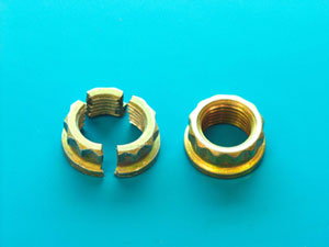
FIGURE 1: Fractured nut as received with an intact nut for comparison.
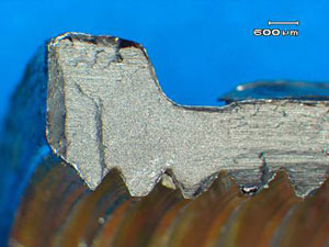
FIGURE 2: Fracture surface showing the brittle cracking region in the centre of the photograph and the surrounding ductile fracture features.
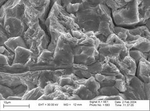
FIGURE 3,4: Scanning electron micrographs of the brittle cracking region.
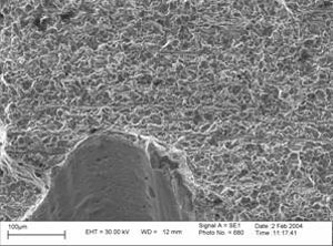
FIGURE 5,6: Scanning electron micrographs showing the features of the ductile fracture region.
During the assembly of Teledyne Continental Motors TSIO-520 M engine s/n 291531R, a number of twelve point nuts (p/n 652541) were found fractured 14 hours after they had been tightened by applying the specified torque (65.8 67.5 ft lbs). The engine assembly process had not been completed.
It was reported that the nuts had been replated with cadmium in accordance with MAF Aviation Services Engineering Order 0071-00 E1. One failed nut and a serviceable nut from the same batch were made available to the ATSB for examination.
Fracture of the failed nut occurred on several longitudinal planes. Fracture initiated from regions of intergranular cracking in the increased section created by the nut flange. Final fracture occurred in a ductile manner.
These features are typical of hydrogen-induced delayed cracking (hydrogen embrittlement), a condition resulting from the presence of hydrogen in the steel and a sustained tensile stress. The effect of thread shape creates a sustained tensile hoop (circumferential) stress in a tightened nut. A particular hazard of cadmium plating high strength steels is the absorption of hydrogen into the base metal. This hazard is countered by baking the parts after plating.
In order to prevent recurrence it is necessary to establish:
If the hydrogen-removal baking heat treatment had been applied to the nuts.
If the baking process was controlled in accordance with process specifications. For example, was the temperature distribution throughout the batch uniform, and was the time of exposure to the specified temperature the same for all nuts in the batch.
If the engineering work order had taken into consideration that the twelve-point nuts are heat treated to a higher strength than the six-point nuts they replace. Longer baking periods may be required to eliminate the hazard of hydrogen embrittlement in higher strength steels.
The Australian Transport Safety Bureau (ATSB) was requested by officers from the Civil Aviation Safety Authority (CASA) to conduct an examination and analysis of several damaged thrust bearing elements from the propeller drive shaft of a Teledyne Continental Motors model GTSIO520M aircraft engine (serial number 810712). Information received indicated that the bearings and accompanying propeller shaft were removed from service during maintenance activities; the discovered damage prompting the aircraft operator to submit a defect report / service difficulty report (SDR) to CASA. A second similar instance of bearing failure and shaft damage was also reported, having occurred on a similar engine (serial number 239168R) approximately one month previously.
The assessment of bearing compliance with the manufacturer's specifications or the direct applicability of the particular bearing part to the engine within which they were installed was not within the scope of the investigation.
Conclusions
The following conclusions, in terms of the bearing failures, were drawn from the examination of the supplied components:
1. The bearings from ESN 810712 had failed as a result of gross, localised frictional overheating, resulting in the physical and microstructural degradation of the bearing alloy. 2. There was no evidence that a manufacturing defect, material anomaly or other deficiency within the bearing components themselves had contributed to the failure. 3. There was no evidence found to suggest that the bearings had been improperly installed. 4. The investigation was not able to directly identify the proximate cause/s of bearing failure, however it is suggested that initial bearing clearances, lubrication and loading were most likely in terms of the nature of the failure and the general function of the assembly.
Factual Information
Report release date: 31/10/2005
Report No. 24/05
Task No. BE/200500003
Occurrence No. BO/200500620
Examination of failed thrust bearings from a Teledyne Continental Motors GTSIO520M engine
Factual Information
1.1 Examination brief
The Australian Transport Safety Bureau (ATSB) was requested by officers from the Civil Aviation Safety Authority (CASA) to conduct an examination and analysis of several damaged thrust bearing elements from the propeller drive shaft of a Teledyne Continental Motors model GTSIO520M aircraft engine (serial number 810712). Information received indicated that the bearings and accompanying propeller shaft were removed from service during maintenance activities; the discovered damage prompting the aircraft operator to submit a defect report / service difficulty report (SDR) to CASA. A second similar instance of bearing failure and shaft damage was also reported, having occurred on a similar engine (serial number 239168R) approximately one month previously.
The assessment of bearing compliance with the manufacturer's specifications or the direct applicability of the particular bearing part to the engine within which they were installed was not within the scope of the investigation.
1.2 Items received
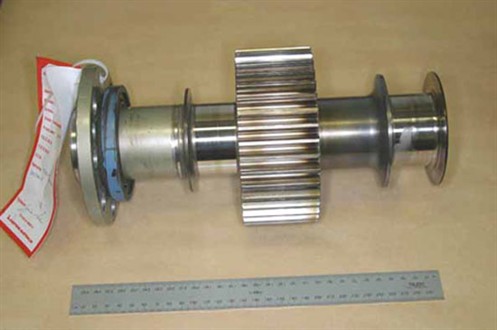
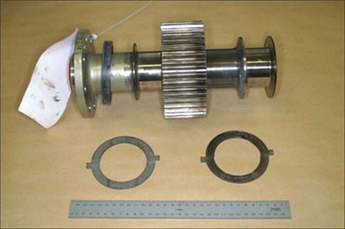
The ATSB received the full set of thrust bearing elements and the propeller shaft from engine serial number (ESN) 810712 (figure 1). The propeller shaft from the earlier occurrence was also provided (figure 2), however the associated thrust bearing set was not available.
Figure 1. Propeller shaft and thrust bearings from engine serial number 810712.
Figure 2. Propeller shaft from engine serial number 239168R.
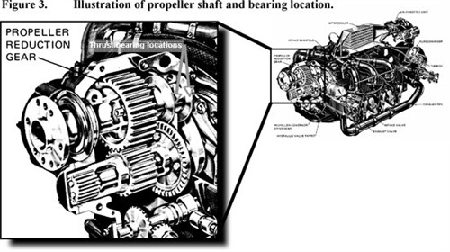
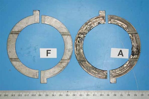
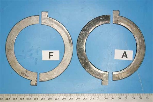
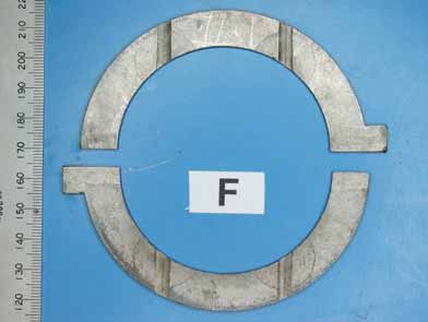
As installed, the thrust bearings comprised two sets of semicircular opposing plates, located against flange elements at the rear of the propeller shaft (figure 3 ). The rear bearings, carrying the primary propeller thrust loads, had sustained extensive mechanical and thermal damage, whereas the forward bearings showed little evidence of abnormal service and were visibly sound (figures 4, 5). The undamaged (forward) bearing set carried the rear surface identification '646260 G'. Damage to the rear bearings prevented the recognition of any similar markings on those items.
Figure 4. Contact (bearing) surfaces of thrust bearings as-received.
Figure 5. Rear (backing) surfaces of thrust bearings as-received.
The thrust bearings were understood to be of tri-metal construction, comprising a surface layer of lead-tin babbit, over a copper-lead intermediate layer on a steel backing. The SDR document indicated the bearing set had operated for 433.4 hours since new installation (TSN).
1.1 Examination findings
1.1.1 Rear thrust bearings
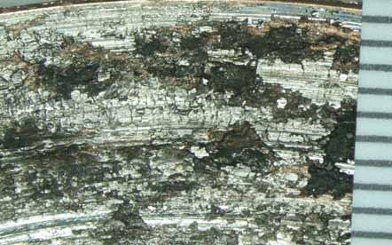
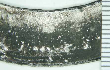
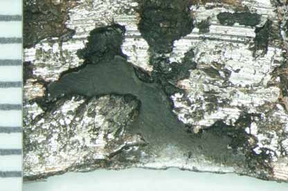
Close visual examination of the set of failed bearings (attachments A - D) showed heavy scoring, gross disruption and partial loss of the bearing alloy from the bearing running (contact) surfaces (figure 6). Partial melting of the surface alloys and other evidence of elevated temperatures was prevalent, as was the blackening and discolouration of the surfaces where alloy loss had occurred. The rear (back) faces of the bearings also showed blackening and the accumulation of melted alloy (figure 7). The lubrication channels on one bearing were partially filled with transferred material that had been melted and dislodged from adjacent areas.
Figures 6 and 7. Low-power microscopic view of a damaged area on the contact and backing surfaces of a damaged thrust bearing.
In isolated regions, the bearing alloy had completely separated from the steel backing, with the affected areas characterised by exposure of the comparatively flat, featureless interfacial surfaces (figure 8).
Figure 8. Area on a damaged bearing showing complete separation of the bearing alloy from the steel backing.
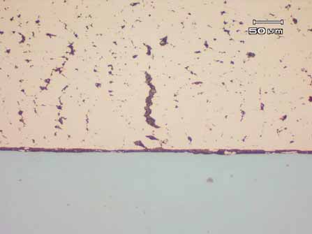
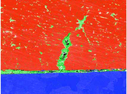
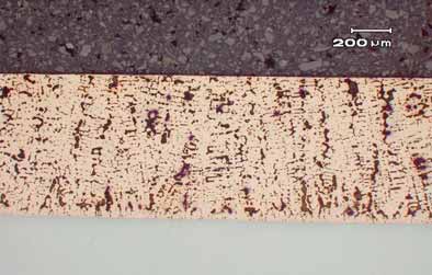
Several metallographic sections taken transversely through one bearing confirmed the basic tri-metal construction, with the intermediate layer presenting as a coarse intermittent network of lead within a copper alloy matrix. In numerous areas, the lead network had interconnected, creating filled fissures (figure 9), the larger of such broaching the external surface. Evidence of lead migration to the steel backing interface was observed at and adjacent to the areas of alloy separation, creating a continuous lead boundary layer approximately 5-10 �m thick.
Figure 9. Cross-sectional microstructure of a damage bearing, showing the agglomeration of lead (dark phase) within the copper bearing alloy and along the backing interface. Unetched.
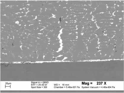
Scanning electron microscopy of the prepared sections confirmed the metallographic observations, with back-scattered electron imaging (figure 10) and x-ray dot mapping (figure 11) graphically illustrating the lead agglomeration and migration to the backing interface.
Figure 10. SEM image of the metallographic section, illustrating the lead migration.
Figure 11. SEM X-ray map confirming the lead migration (green phase) within the copper alloy (red phase) and at the steel (blue phase) interface.
1.2.1 Forward thrust bearings
In contrast with the rear elements, the forward bearings presented in an essentially undamaged condition (figure 12), with very little evidence of metal-to-metal surface contact and no evidence of thermal distress, overheating or physical degradation. The rear surfaces were not fretted or rubbed to any significant extent and showed no indication of improper seating, movement or miss-installation.
Several metallographic sections, taken in a similar sense to those from the rear bearings, presented a similar general microstructure, with the intermediary alloy layer showing a distinct as-cast (dendritic) distribution of lead within the copper alloy matrix (figure 13). No evidence of fissuring or lead migration to the backing interface was observed within the cross-sections studied.
Typical thicknesses of the bearing component layers and backing were established by measurement under the SEM, i.e. Surface Pb-Sn babbit: 7 - 10 �m (0.007 - 0.010 mm) Intermediate Cu-Pb alloy: 715 - 725 �m (0.715 - 0.725 mm) Steel backing: 1,650 �m (1.65 mm)
Figure 12. Undamaged running surfaces of the forward bearing set.
Figure 13. Metallographic cross-section through an undamaged bearing - no lead migration to the alloy interface.
1.2.2 Propeller shafts
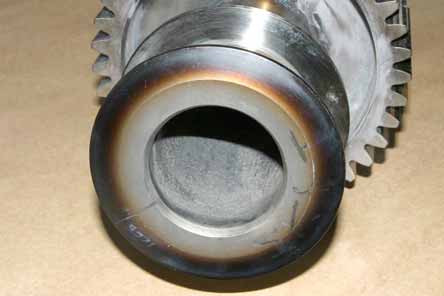
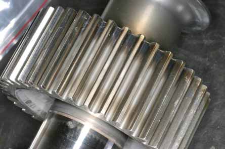
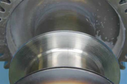
Both propeller shafts showed distinct discolouration and evidence of localised heating in a band around the back face of the rear thrust flange (figure 14). Similar discolouration was also noted in a band around the rearmost ends of the reduction gear teeth (figure 15), however the tooth contact surfaces themselves showed no evidence of distress, uneven wear or excessive localised friction.
The inside (bearing) surfaces of the rear shaft flanges (those working against the failed bearing elements) showed heavy wear and circumferential scoring around the contact path (figure 16). In contrast, the opposite flange faces (figure 17) showed little if any physical manifestation of service - abnormal or otherwise.
Figure 14. Discolouration of the rear thrust flange surface typifying the localised overheating.
Figure 15. Discolouration (similar to figure 12) evident on the ends of the reduction gear teeth.
Figure 16. Appearance and extent of scoring and wear sustained by the propeller shaft rear thrust flange contact surface.
Figure 17. Forward thrust flange (opposite that shown above), presenting in sound condition.
Analysis
Damage to the propeller shaft thrust bearing assembly was limited to the rear bearings and shaft flanges, those being the components carrying the primary propeller thrust loads when under power. The forward bearings and shaft flanges were undamaged and showed no indication of anomalous service.
The rear propeller shaft thrust bearings from ESN 810712 had failed as a result of gross localised overheating. The local discolouration of the shaft flanges and adjacent surfaces and the partial melting and microstructural changes within the bearing alloy attested to the excursion in temperatures to a level well above the normal component operating range. The physical loss of sections of bearing alloy from the backing material was a direct manifestation of the overheating, with the elevated temperatures causing the lower melting point lead alloy to agglomerate and migrate to the steel interface, where it weakened the normal bond and allowed the break-up and separation of the bearing material. There was no evidence of a deficiency within the construction or make-up of the bearings examined, nor was there any evidence that the bearings had been improperly installed.
In a general sense, the overheating of bearings results from the generation of frictional heating at a rate greater than the assembly and environment is able to conduct it away. Heating, from surface and lubricant frictional effects, is a function of numerous interrelated factors including:
bearing operating (transmitted) loads
clearances
lubricant properties
lubricant quantities and flow rates
relative surface speeds
surface conditions and finishes
bearing materials
The investigation was not able to directly identify which of the identified factors were contributory to the failures sustained, however it is suggested that issues relating to the initial bearing clearances, lubricant and operating (thrust) loads would be the most likely in terms of the general nature and function of the assembly.
Conclusions
The following conclusions, in terms of the bearing failures, were drawn from the examination of the supplied components:
The bearings from ESN 810712 had failed as a result of gross, localised frictional overheating, resulting in the physical and microstructural degradation of the bearing alloy.
There was no evidence that a manufacturing defect, material anomaly or other deficiency within the bearing components themselves had contributed to the failure.
There was no evidence found to suggest that the bearings had been improperly installed.
The investigation was not able to directly identify the proximate cause/s of bearing failure, however it is suggested that initial bearing clearances, lubrication and loading were most likely in terms of the nature of the failure and the general function of the assembly.
On 4 October 2010, the pilot of a Robinson Helicopter R22 Beta, registered VH‑THI, was conducting cattle mustering operations on a station property about 170 km east of Katherine, Northern Territory. During those operations, the helicopter collided with the ground. The pilot, the sole occupant of the helicopter, sustained fatal injuries. The helicopter was seriously damaged.
The investigation determined that the collision with terrain was probably a result of engine stoppage while operating at low altitude. The investigation also determined that the helicopter was serviceable prior to the collision with the terrain and that the engine stoppage was probably due to fuel exhaustion.
The nature of mustering operations had the potential to divert the pilot's attention away from other safety-critical tasks, such as monitoring the helicopter's fuel state. The circumstances of the accident highlight the importance of pilots and operators using a system to independently verify the fuel quantity in their aircraft's tanks.