Incorrect configuration for landing involving Airbus A320, VH-VQK, Ballina/Byron Gateway Airport, New South Wales, on 18 May 2018
Final report
Safety summary
What happened
On the morning of 18 May 2018, an Airbus A320 aircraft, registered VH-VQK, was being operated on a regular public transport flight by Jetstar Airways. The flight departed from Sydney, New South Wales for Ballina/Byron Gateway Airport, New South Wales.
The flight crew conducted a go-around on the first approach at Ballina because the aircraft’s flight path did not meet the operator’s stabilised approach criteria. On the second approach, at about 700 ft radio altitude, a master warning was triggered because the landing gear had not been selected DOWN. The flight crew conducted a second go-around and landed without further incident on the third approach.
What the ATSB found
The flight crew did not follow the operator’s standard procedures during the first go-around and subsequent visual circuit at 1,500 ft. In particular, the flaps remained at Flaps 3 rather than Flaps 1 during the visual circuit. This created a series of distractions leading to a non-standard aircraft configuration for a visual circuit. Limited use of available aircraft automation added to the flight crew’s workload.
During the downwind leg following the first go-around, the flight crew did not select the landing gear DOWN as they had commenced the configuration sequence for landing at the Flaps 3 setting. Furthermore, the flight crew incorrectly actioned the landing checklist, which prevented the incorrect configuration for landing being identified and corrected.
Safety message
Unexpected events during approach and landing phases can substantially increase what is often a high workload period. Adherence to standard operating procedures and correctly monitoring the aircraft and approach parameters provides assurance that a visual approach can be safely completed. The selection of inappropriate auto-flight modes, unexpected developments, or any confusion about roles or procedures can contribute to decisions and actions that increase the safety risk to the aircraft and its passengers.
The ATSB SafetyWatch highlights the broad safety concerns that come out of our investigation findings and from the occurrence data reported to us by industry. Handling of approach to land is one of these priorities.
The occurrence
First approach
On the morning of 18 May 2018, an Airbus A320 aircraft, registered VH-VQK, was being operated on a regular public transport flight by Jetstar Airways. The flight departed from Sydney, New South Wales for Ballina/Byron Gateway Airport, New South Wales. The captain was the pilot monitoring (PM) and the first officer (FO) was the pilot flying (PF).[1]
During the flight, the flight crew discussed and planned their arrival into Ballina. The forecast weather conditions were good with clear visibility and light winds. The FO suggested that they conduct a visual approach. Given that the conditions were good and the captain could see the airport from 50 NM the captain agreed. The FO then programmed the Flight Management Guidance System for the descent and arrival and carried out an approach briefing for a visual approach to runway 24. The FO recalled that he briefed the initial actions for a go-around, however, the flight crew did not discuss subsequent actions including the visual circuit[2] procedure.
At 1042 Eastern Standard Time,[3] the flight crew commenced descent during which they broadcast the required radio calls for their arrival on the common traffic advisory frequency (CTAF). During this period they became aware of a helicopter conducting right circuits at the airport.
Descending through about 2,100 ft the FO disconnected the autopilot and manually flew the aircraft. During manoeuvring to join a left base, the aircraft’s airspeed and altitude were both higher than a normal approach profile. The captain recognised the problem and recalled thinking that a go-around would be required, but due to the circuit traffic he wanted the aircraft established on final approach before commencing the go-around procedure.
The FO continued the approach and targeted a vertical speed of 1,000 ft/min descent and commenced a turn onto the final approach. Recorded flight data showed a peak vertical speed of about 1,300 ft/min at about 730 ft, and the aircraft still well above the desired vertical profile. Still turning onto the final approach the FO observed three white fly-down lights on the visual approach slope indicator system (VASIS).[4]
First go-around
At 500 ft above ground level (AGL) the aircraft automatically generated a callout of ‘five hundred’ and the captain commanded a go-around by calling out ‘not stable’. The FO commenced the go-around procedure (Figure 1).
Recorded flight data showed the aircraft was about 450 ft AGL when the go-around commenced. With take-off/go-around (TOGA) thrust set and Flaps 3 selected, the aircraft approached the circuit altitude of 1,500 ft about 10 seconds later.
As the FO levelled the aircraft it accelerated quickly toward the Flaps 3 limit speed (185 kt). The FO called for the approach phase[5] to be activated, which would have reduced the autothrust’s target speed from green dot speed[6] to 139 kt, and the captain went to action this request.
However, due to the aircraft’s acceleration, the FO believed the autothrust system would not prevent a flap overspeed prior to the approach phase becoming active. Consequently, he retarded both thrust levers to IDLE. This action disengaged the autothrust and generated an Electronic Centralised Aircraft Monitoring (ECAM) caution message (AUTO FLT A/THR OFF).
The captain heard the associated aural master caution chime, scanned the instruments and observed the aircraft’s pitch attitude being 10° nose up with Flaps 3 and idle thrust. He immediately commanded the FO to place both thrust levers back into the climb detent and re-engage the autothrust system. The FO subsequently reported that he had already commenced these actions at that time.
Figure 1: Flight path of VH-VQK during incident flight
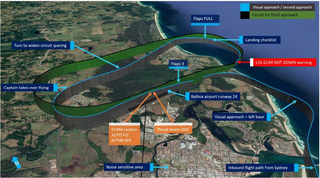
Source: Google Earth annotated by ATSB.
Circuit for second approach
The FO commenced a left turn to conduct a standard left circuit for runway 24, however, the captain instructed the FO to conduct a right circuit. The captain later recalled his decision to conduct a non-standard right circuit was predicated on a number of reasons, but mainly due to the helicopter conducting right circuits and the noise sensitive area over the Ballina township to the south-east of runway 24 (Figure 1).
During the turn onto the downwind leg of the circuit, the FO offered the PF duties to the captain. The captain took control of the aircraft and the FO reverted to PM duties. The captain continued to fly the aircraft manually with the autopilot off and the autothrust engaged.
During the downwind leg, the captain recalled observing on his navigation display that the aircraft was positioned too close to the runway. Recorded flight data indicated the aircraft was about 1.2 NM abeam the runway rather than the captain’s desired 2.0 NM spacing. The captain turned left to widen the circuit spacing.
The flight crew completed the after take-off checklist. The captain noted that the flaps were set to Flaps 3 rather than the normal Flaps 1 configuration for a visual circuit, and he instructed the FO to let the flaps remain at that setting as he wanted to prioritise safely flying the aircraft in the circuit area.
As the captain commenced the turn onto the base leg, he scanned the ECAM upper display and observed the flaps were still set at Flaps 3. He commanded Flaps FULL, which the FO selected.
Both the captain and the FO stated they completed the landing checklist at about 950 ft AGL, which included the ECAM landing memo, and continued the approach.
At about 700 ft radio altitude (RA), a master warning for L/G GEAR NOT DOWN was triggered because the landing gear had not been selected DOWN. Recorded flight data showed that about 4 seconds after the master warning, the landing gear was selected DOWN. A further 2 seconds later the captain selected the thrust levers to TOGA and commenced a second go-around. The aircraft’s lowest recorded height was about 670 ft AGL.
Second go-around
The flight crew reconfigured the aircraft to gear UP and Flaps 1, as per the go-around procedure. The captain elected to continue manually flying the aircraft and conducted a second non-standard right circuit.
At about this time, the pilot of a Cessna 172 inbound from the north made radio calls advising aircraft at Ballina of his intention to join the (left) circuit for landing. The captain of the A320 provided instructions to the Cessna 172 pilot over the radio to confirm separation between the two aircraft.
On the downwind circuit leg for the third approach, the A320’s traffic collision avoidance system (TCAS) generated a traffic advisory (TA). The flight crew had remained in visual contact with the Cessna 172 and estimated its position to be about 2.0 NM to the north and about 800 ft above them. No further actions were required from either flight crew in relation to the TCAS TA.
On the third approach the flight crew configured the aircraft in accordance with the operator’s visual circuit procedures and actioned the landing checklist, including the landing memo items from the checklist. The aircraft landed on runway 24 without further incident.
__________
- Pilot Flying (PF) and Pilot Monitoring (PM): procedurally assigned roles with specifically assigned duties at specific stages of a flight. The PF does most of the flying, except in defined circumstances; such as planning for descent, approach and landing. The PM carries out support duties and monitors the PF’s actions and aircraft flight path.
- Circuit: a specified pattern flown by aircraft when taking off or landing while maintaining visual contact with the airfield. Typically rectangular in shape and include pattern legs; upwind, crosswind, downwind, base and final.
- Eastern Standard Time (EST) was Coordinated Universal Time (UTC) + 10 hours.
- VASIS: a visual approach slope indicating system that uses high intensity lighting to assist pilots identify the correct glide path to the runway. The system for runway 24 at Ballina was an AT-VASIS, and three white lights indicated the aircraft was too high.
- Approach phase is a function of the Flight Management Guidance System. When activated it automatically commands slower aircraft speeds during an approach and will appropriately reduce airspeed to the respective flap manoeuvring speed as configuration is changed for landing.
- Green dot speed is the operational speed in the clean configuration and gives an estimate of the speed for best lift-to-drag ratio.
Safety analysis
Introduction
Incidents such as the incorrect configuration of an air transport aircraft for landing are rarely the result of a single action or identifiable event. Instead, a number of factors combine to result in an unintended outcome; which in this case was the conduct of the second approach to Ballina/Byron Gateway Airport without the landing gear selected DOWN.
Although the incident was highly undesirable, it should be noted that the aircraft’s warning system effectively alerted the flight crew to the problem, and the crew responded promptly to the warning and initiated a second go-around.
Conduct of the first go-around
Due to the unstable approach on the first attempt to land, the flight crew appropriately performed a go-around.
An all engines go-around is a very dynamic procedure with high accelerations created by the application of take-off/go-around (TOGA) thrust. When performed at a low aircraft weight with low altitude level off, such as a 1,500 ft circuit height, it can be a demanding manoeuvre. It requires flight crews to perform a significant number of actions in a short period of time with all of them related to important changes of attitude, thrust, flight path, landing gear and flap configuration and flight modes. The actions need to be performed in the correct order, with a high level of coordination between the crew.[8]
The initial actions of the first go-around manoeuvre, up until reaching the thrust reduction altitude, were performed correctly. However, instead of retracting the flaps on schedule to Flaps 1, the first officer (FO) called for the approach mode to be activated first in an attempt to reduce the aircraft’s acceleration. Concerned about a potential flap overspeed, the FO then retarded the thrust levers past the climb detent to IDLE. This action de-activated the autothrust system and its protections, which limit thrust to help prevent overspeeds. With Flaps 3 still set and about 10° nose-up pitch attitude, the aircraft performance deteriorated, requiring intervention by the captain.
Visual circuit
In this incident, several distractions caused the flight crew to deviate from the operator’s normal visual circuit procedures at Ballina. The FO was anticipating a left circuit to be flown in accordance with the published procedure for runway 24. However, the captain commanded a non-standard right circuit for various reasons, which he had not previously advised the FO during the approach briefing or the subsequent approach.
As the aircraft was being turned onto downwind the flight crew were presented with further distractions including the handover of flying duties to the captain and then correcting the lateral flight path spacing in the circuit. The captain continued to manually fly the aircraft, which added to his workload. Accordingly, the captain elected to concentrate on flying the aircraft and have the FO conduct the required checklists and radio calls. As the captain prioritised tasks he chose to remain at Flaps 3, which was permissible and safe, but not the operator’s standard configuration for a visual circuit which was Flaps 1.
Landing configuration
Linking an aircraft’s normal procedures with an identifiable phase of flight is designed to assist a flight crew’s procedural recall. During most approaches, a flight crew will follow the same sequence for configuring flaps, landing gear and spoilers and conducting the landing checklist.
The operator’s sequence of configuring the aircraft for landing required the landing gear to be selected DOWN prior to the selection of Flaps 3. As the captain turned on to the final approach during the second approach, he scanned the flight instruments, observed Flaps 3 already set and instinctively commanded Flaps FULL, which was the normal sequence from Flaps 3. The FO selected Flaps FULL but then also turned his attention to monitoring the aircraft’s flight path. As such, neither of the flight crew were aware that the landing gear had not been selected DOWN.
Landing checklist
The flight crew flew the second visual circuit at about 1,500 ft. Therefore, the Electronic Centralised Aircraft Monitor (ECAM) landing memo logic was not reset after the go-around. When the flight crew performed the landing checklist on the second approach, with the aircraft at about 950 ft, the landing memo would not have been displayed on the Engine/Warning Display.
The absence of the landing memo should have prompted the flight crew to perform the items of the landing checklist as a ‘read-and-do’ checklist. Had they read the required actions from the checklist, both the captain and FO would have been required to independently check and announce that the landing gear was down. This method should have effectively ‘trapped’ their error.
When the landing memo did appear at 800 ft, both of the flight crew were situationally focused on intercepting the final approach path and performing radio calls. Neither the captain nor the FO recalled seeing the landing memo appear on the E/WD; which would have had the landing gear item in blue text. Both the captain and FO were subsequently alerted to the incorrect configuration for landing by a master warning message triggered at about 700 ft.
It would be ideal if the aircraft’s systems were designed such that the landing memo became available during the 1,500 ft visual circuit. However, system design is often a matter of compromise and there is also a need to minimise unnecessary complexity. Airbus set a minimum height of 2,200 ft to prevent spurious display of the landing memo during take-off and to prevent display flickering during an approach.
The exact reasons why both crew did not notice the absence of the landing memo when completing the landing checklist are unclear. However, a combination of workload and expectancy are often involved in such errors (Wickens and McCarley, 2008).[9] In this case, the flight crew probably expected the memo to be there, given that it is normally present at that phase of flight. In addition, the absence of something that should be present is often more difficult to detect than the presence of something that should not be there (for example, Thomas and Wickens, 2006).[10]
Overall, this occurrence reinforces the importance of using normal procedures, and minimising and managing the effects of workload during critical phases of flight.
__________
- Further discussion on the challenges of all-engine go-arounds in modern aircraft is provided in the ATSB investigation report AO-2012-116, Flap overspeed and altitude exceedance during go-around, Airbus A321, VH-VWY, Cairns Airport, Queensland, 3 September 2012. See also Bureau d’Enquêtes et d’Analyses pour la sécurité de l’aviation civile (BEA) 2013, Study on aeroplane state awareness during go-around. Available from www.bea.aero.
- Wickens, CD & McCarley, JS 2008, Applied attention theory, CRC Press Boca Raton, FL.
- Thomas, LC & Wickens, CD 2006, ‘Effects of battlefield display frames of reference on navigational tasks, spatial judgements, and change detection’, Ergonomics, vol.49, pp.1154-1173.
Context
Flight crew information
The captain held an Air Transport Pilot (Aeroplane) Licence, a multi-engine command instrument rating and a Class 1 Aviation Medical Certificate. He had over 11,000 hours flying experience, of which over 3,000 hours were on the A320/A321. The captain was a check pilot for the operator; however, this flight was rostered as a normal line flight, with no check or training functions scheduled.
The first officer (FO) held a Commercial Pilot (Aeroplane) Licence and was appropriately qualified for the flight. He had about 1,600 hours flying experience, of which about 1,400 hours were on the A320/A321.
Both flight crew signed on for duty at Sydney Airport at 0510 and operated a flight from Sydney to the Gold Coast then return to Sydney. The flight to Ballina/Byron Gateway was their third flight of the day. Both flight crew reported that they had a reasonable amount and quality of sleep the night before and did not feel tired at the time of the occurrence. The captain had conducted flights the previous day and the FO had conducted flights on the two previous days, and neither reported any problems with their sleep prior to those days’ flights.
Both the captain and the FO had operated into Ballina on many previous occasions. The FO advised that this was only the third or fourth time he had operated into Ballina as pilot flying.
Go-around procedure
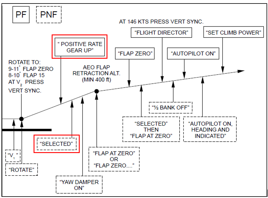
The operator’s procedures stated the pilot flying (PF) must conduct an immediate go-around if the pilot monitoring (PM) called ‘500 not stable’. The operator’s go-around procedure (based on the aircraft manufacturer’s procedure) detailed a sequence of actions that the PF and PM were required to perform, as summarised in Figure 2.
For most go-arounds, once the aircraft reached the nominated thrust reduction altitude, the procedure required the thrust levers to be placed into the climb detent by the PF. This action would activate the autothrust system.
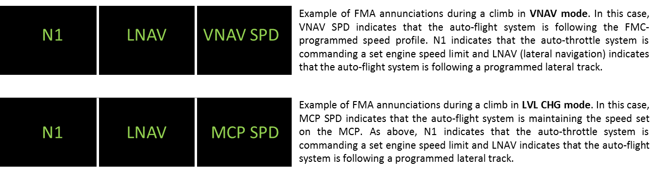
In SPEED mode, the autothrust adjusts the thrust in order to acquire and hold a speed target and does not allow speed excursions beyond the maximum speed for each flap configuration. The flaps are not automatically retracted from the Flaps 3 configuration.[7] As the aircraft accelerates, the flight crew would need to retract flaps to the required position. The operator’s procedure when conducting a visual circuit following a go-around was normally to re-configure the aircraft to the Flaps 1 position.
Figure 2: Airbus A320 go-around profile
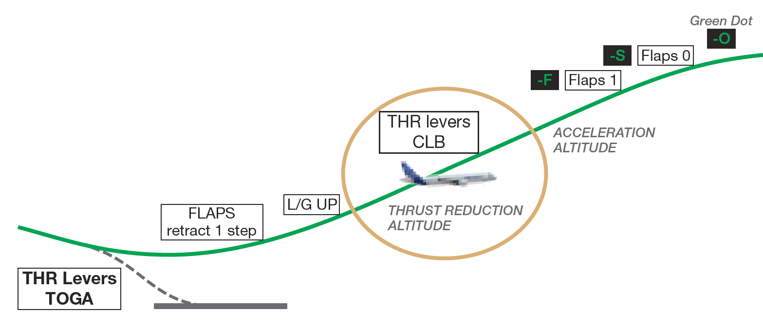
Source: Airbus.
Visual circuit procedure
The operator’s Flight Crew Operating Manual contained procedures for flying a visual circuit. The procedure detailed a visual circuit be flown at 1,500 ft AGL with Flaps 1. Prior to turning onto the base leg of the circuit, the flight crew should normally select Flaps 2, select landing gear DOWN and arm the spoilers. On the base leg, the flight crew should normally select Flaps 3 followed by Flaps FULL (if required). Flight crews would then perform the landing checklist.
ECAM landing memo
The Airbus A320 Electronic Centralised Aircraft Monitor (ECAM) presents data to flight crew on two displays: the Engine/Warning Display (E/WD) and the System Display (SD). Data presented includes:
- primary engine indications, fuel quantity, landing gear, flap and slat position
- warning and caution alerts, or memos
- synoptic diagrams of aircraft systems, and status messages.
Memos are displayed on the lower section of the E/WD, and they list functions or systems that are temporarily used for normal operations. The display uses colour codes, which indicate to flight crew the importance of the indication. Green indicates the item is operating normally, and blue indicates there are actions to be carried out.
The landing memo is displayed when the aircraft is in the approach phase below 2,000 ft. However, after a go-around the system logic requires the aircraft climb above 2,200 ft radio altitude (RA) in order for the landing memo to reset. If the aircraft conducts a circuit lower than 2,200 ft the landing memo will not be displayed on the E/WD until 800 ft RA on the next approach.
Figure 3: Airbus A320 flight deck and E/WD landing memo
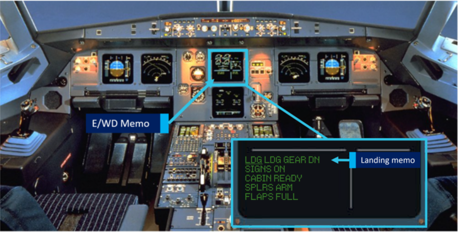
Source: Airbus modified by ATSB.
Landing checklist
As part of the operator’s stabilised approach criteria the landing checklist was required to be completed prior to 1,000 ft AGL. The checklist included an item for ECAM MEMO. When actioning that item the captain and FO were required to independently look at the ECAM MEMO on the E/WD, confirm that there was no blue text and, on observing that, announce ‘landing, no blue’ in response to the checklist item.
In the case of the landing memo not being displayed on the E/WD (as in the event of a go-around and visual circuit below 2,200 ft), the flight crew were required to read, check and announce the landing memo items listed on the checklist below the item ECAM MEMO.
Figure 4: Jetstar A320 landing checklist
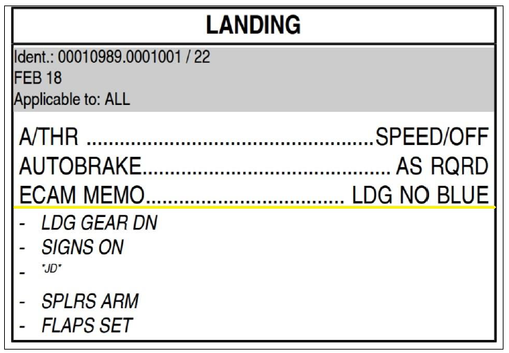
Source: Jetstar.
__________
Findings
These findings should not be read as apportioning blame or liability to any particular organisation or individual.
- During the first go-around, the flight crew did not fully complete the standard go-around procedure, resulting in the aircraft’s flaps remaining at Flaps 3 rather than Flaps 1 during the subsequent visual circuit at 1,500 ft.
- During the downwind leg following the first go-around, the flight crew did not select the landing gear DOWN, as they had commenced the configuration sequence for landing at the Flaps 3 setting.
- The flight crew did not identify that, because the aircraft had not climbed through 2,200 ft, the landing memo had not been reset and was not displayed.
- Following both go-arounds, the captain elected to conduct non-standard right circuits. This increased the potential for traffic conflicts with other aircraft, and flight crew workload managing such conflicts.
Safety action
Whether or not the ATSB identifies safety issues in the course of an investigation, relevant organisations may proactively initiate safety action in order to reduce their safety risk. The ATSB has been advised of the following proactive safety action in response to this occurrence.
Jetstar Airways
As a result of this occurrence, Jetstar Airways has advised the ATSB that both flight crew members attended debriefings with flight operations management and were provided with specific simulator and line flying training related to the occurrence.
Purpose of safety investigations & publishing information
Purpose of safety investigationsThe objective of a safety investigation is to enhance transport safety. This is done through:
It is not a function of the ATSB to apportion blame or provide a means for determining liability. At the same time, an investigation report must include factual material of sufficient weight to support the analysis and findings. At all times the ATSB endeavours to balance the use of material that could imply adverse comment with the need to properly explain what happened, and why, in a fair and unbiased manner. The ATSB does not investigate for the purpose of taking administrative, regulatory or criminal action. TerminologyAn explanation of terminology used in ATSB investigation reports is available here. This includes terms such as occurrence, contributing factor, other factor that increased risk, and safety issue. Publishing informationReleased in accordance with section 25 of the Transport Safety Investigation Act 2003 Published by: Australian Transport Safety Bureau © Commonwealth of Australia 2019

Ownership of intellectual property rights in this publication Unless otherwise noted, copyright (and any other intellectual property rights, if any) in this report publication is owned by the Commonwealth of Australia. Creative Commons licence With the exception of the Coat of Arms, ATSB logo, and photos and graphics in which a third party holds copyright, this publication is licensed under a Creative Commons Attribution 3.0 Australia licence. Creative Commons Attribution 3.0 Australia Licence is a standard form licence agreement that allows you to copy, distribute, transmit and adapt this publication provided that you attribute the work. The ATSB’s preference is that you attribute this publication (and any material sourced from it) using the following wording: Source: Australian Transport Safety Bureau Copyright in material obtained from other agencies, private individuals or organisations, belongs to those agencies, individuals or organisations. Where you wish to use their material, you will need to contact them directly. |
Occurrence summary
| Investigation number | AO-2018-042 |
|---|---|
| Occurrence date | 18/05/2018 |
| Location | near Ballina/Byron Gateway Airport |
| State | New South Wales |
| Report release date | 10/12/2019 |
| Report status | Final |
| Investigation level | Short |
| Investigation type | Occurrence Investigation |
| Investigation status | Completed |
| Mode of transport | Aviation |
| Aviation occurrence category | Incorrect configuration |
| Occurrence class | Incident |
| Highest injury level | None |
Aircraft details
| Manufacturer | Airbus |
|---|---|
| Model | A320-232 |
| Registration | VH-VQK |
| Serial number | 2651 |
| Aircraft operator | Jetstar Airways |
| Sector | Jet |
| Operation type | Air Transport High Capacity |
| Departure point | Sydney, NSW |
| Destination | Ballina/Byron Gateway, NSW |
| Damage | Nil |