After consultation with the ATSB, the operator developed and instigated a new inspection and monitoring procedure TSI-146-24-004. This includes the fitment of heat sensitive decals to the RCCB contactor chambers and recording of the observed operating temperatures into a database at regular intervals. This is then used to monitor for any upward trends in operating temperatures of the RCCB.
Summary
Passengers had boarded the BAe 146 prior to departure. When the pilot in command selected the start master switch to No. 1 engine in preparation for engine start, the aircraft's AC power supply immediately failed. The indications included the "APU GEN OFF LINE" annunciator and cockpit/cabin emergency lighting illuminating. The auxiliary power unit (APU) generator was reselected on to restore AC power but immediately after the switch selection was made, the AC power failed again. The crew also noticed a small amount of smoke drifting past the cockpit overhead emergency lighting. They immediately turned off the start power and began disembarking the passengers.
While the passengers were disembarking, the co-pilot checked the electrical equipment bay located on the outside of the aircraft. He found a small fire in an electrical rack, which he extinguished with the cockpit's portable fire extinguisher. The co-pilot also disconnected the aircraft batteries. The off-airport rescue and fire fighting service (RFFS) was called and remained in attendance until the arrival of engineering staff.
Inspection by maintenance personnel revealed that the remote control circuit breaker (RCCB) which controls the AC-powered hydraulic pump had failed.
The RCCB was forwarded to the ATSB and dismantled. It was found to have been subjected to extreme heat, which destroyed two of the three main AC contacts within the RCCB. The level of internal damage precluded determination of why the RCCB had failed. However, it was found that as a consequence of the RCCB design, the three main contactor chambers were open to air, dirt and moisture during normal operations. The investigation could not determine if this design feature was a factor in the electrical malfunction.
The AC-powered hydraulic pump internal thermal switch wire was found to be pinched between the impeller housing and the stator, effectively creating a short circuit to ground. The effect of this short circuit would only be noticed when the pump had exceeded an operating temperature of 204 degrees Celsius. Although the pump did not display any outward signs of excessive heat, it did exhibit a general state of deterioration commensurate with the extended time in service for this unit. Clearly the RCCB was subjected to excessive current load. This caused a catastrophic internal failure and the subsequent heat generated by the failure led to molten metal escaping from the RCCB main contactor compartment. The molten metal then flowed across two energised power cables, which resulted in the short-circuiting of two AC power phases.
The RCCB was located in an equipment bay that was not monitored by fire or smoke detection devices. The technical crew was alerted to the fire by smoke in the cockpit, system failures and a fire that the co-pilot noticed when he gained access to the RCCB through an external bay door. It was possible to access the equipment bay, which held the RCCB, from the cockpit. If a similar problem were to occur, opening the access door during flight would introduce more oxygen to the fire and vent smoke and noxious fumes into cabin, threatening crew and passengers.
The airframe manufacturer's failure-trend data for the RCCB was examined and it was determined that the equipment exhibited very high reliability in service. Consequently, the probability of recurrence of this type of failure was considered to be low.
As a result of this incident, and following contact between the ATSB and the aircraft manufacturer, several temporary revision changes have been made to the aircraft maintenance manuals for the Beechcraft 1900,1900C and 1900D. These revisions detail changes to the fire bottle activation testing procedures, and introduce a check to ensure that sufficient voltage is available at the fire bottle squib to operate the bottle. The manufacturer has also introduced a more secure method of attaching the landing light wiring in this area on all of the new production aircraft. This method involves utilising a length of spirally wrapped electrical insulation tubing around the wiring leading to the landing lights and stand-by fuel pump. An extra cable tie and tubing stand-off is also utilised to further guarantee wiring separation from the fuel lines in the area.
Following discussions with the ATSB, the Civil Aviation Safety Authority issued airworthiness directive, AD/BEECH/1900/30, effective on the 20 September 1999. This AD details the requirement to inspect the affected left and right wing zones on 1900 aircraft for evidence of electrical wiring chafing and rub or burn marks on the aluminium fuel lines.
The Australian Transport Safety Bureau, (formerly the Bureau of Air Safety Investigation) issued the following interim recommendations on the 21 September 1999. The responses to these recommendations, without alteration to the text, are attached to this report.
The Australian Transport Safety Bureau classifies the responses according to the guidelines in the Bureau's Policy and Procedures manual. These response classifications are as follows:
CLOSED - ACCEPTED
ATSB accepts the response without qualification.
CLOSED - PARTIALLY ACCEPTED
ATSB accepts the response in part but considers other parts of the response to be unsatisfactory. However, ATSB believes that further correspondence is not warranted at this time.
CLOSED - NOT ACCEPTED
ATSB considers the response to be unsatisfactory but that further correspondence is not warranted at this time.
OPEN
The response does not meet some or all of the criteria for acceptability for a recommendation that ATSB considers to be significant for safety. ATSB will initiate further correspondence.
IR19990172
The Australian Transport Safety Bureau (formerly the Bureau of Air Safety Investigation) recommends that the Civil Aviation Safety Authority alert all operators to initiate an immediate wiring and fuel-line inspection of the Beech 1900 fleet in Wing Zones 531 and 631 as a matter of the highest priority.
On the 27 October 1999, the following response to IR199900172 was received from the Civil Aviation Safety Authority:
CASA has reviewed Air Safety Interim Recommendation IR 9990172. Your staff briefed the relevant CASA specialist staff on the circumstances surrounding the inflight fire in VH-NTL on 16 September 1999. The serious nature of the incident prompted this Authority to issue AD/BEECH 1900/30, Electrical Loom Inspection, on 17 September 1999, to be effective on 20 September 1999 and requiring an inspection of the area before further flight.
A report has now been received for all aircraft on the Australian register, showing that no similar problems exist in Beech 1900C/D aircraft operated in Australia. None-the -less, the conclusions in your report are generally supported. CASA will seek advice from the manufacturer regarding the appropriateness of the electrical circuit protection and the instructions for maintenance of this wire.
Response classification - CLOSED-ACCEPTED
IR19990173
The Australian Transport Safety Bureau (formerly the Bureau of Air Safety Investigation) recommends that the Federal Aviation Administration alert all operators to initiate an immediate wiring and fuel-line inspection of the Beech 1900 fleet in Wing Zones 531 and 631 as a matter of the highest priority.
On the 7 October 1999, the following response to IR199900173 was received from the Federal Aviation Administration:
The Wichita Aircraft Certification Office (ACO) received the following Safety Recommendation on October 1, 1999:
Safety Recommendation 99.371; "The Bureau of Air Safety Investigation recommends that the Federal Aviation Administration alert all operators to initiate an immediate wiring and fuel-line inspection of the Beech 1900 fleet in Wing Zones 531 and 631 as a matter of the highest priority."
The original 1900s and 1900Cs (serial numbers beginning with "UA" and "UB" respectively) use a fuel bladder versus a total wet wing in the later 1900Cs (serial numbers beginning with 'UC") and 1900D series (serial numbers that begin with "UE"). The specific area of concern for this Safety Recommendation is applicable only to the 'UC" serial numbered 1900Cs and 1900D aircraft models because the components involved in this incident are located elsewhere in the Model 1900s and original 1900Cs ('UA"s and "UB" s). However, there are some wiring and fuel systems components in this general area in these earlier model aircraft ("UA" and "UB" serial numbers) so the review included them as well.
In the FAA's investigation, which included looking at the incident pictures, reviewing new production 1900D aircraft and reviewing the 1900, 1900C and 1900D Maintenance Manuals, the following items were noted:
The incident pictures revealed "tie-wrap" impressions on the plumbing in the area where the arcing is believed to have occurred. This indicates that at one time, the tie-wraps that are used to construct the stand-offs for the electrical wiring were in place.
The 1900 and 1900C Maintenance Manual in Section 5-20-02, page 5, (First 200-hour-interval detailed inspection) for item 13.b. states "LEADING EDGE AND NACELLE PLUMBING AND WIRING Zone inspection areas: 511, 521, 522, 531, 541, 611, 621, 622, 631 and 641. Wing panel inspection areas: 54, 55, 56, 57, 58, 59, 60, 61 (UA-1 and after, UB-1 and after); 23, 24, 25, 26, 27, 28 and 29 (UC-1 and after). b. Check the wiring for chafing and security of attachment." In addition, on the same page of the same section for item 14.a states, "PLUMBING Zone inspection areas: 531, 532, 631 and 632. Wing panel inspection areas: 4, 17, 18 (UA- 1 and after, UB- 1 and after); 8, 9, 11, 12, 15, 18, 21, 23, 25, 29 (UC- 1 and after). a. Visually check for leaks, chafing or damage and proper attachment." This inspection is one of six that are to be repeated every 1200 hours per section 5-20-00, page 3 of the same manual.
The 1900D Maintenance Manual in Section 5-20-02, page 204, (First 200-hour-interval detailed inspection) for item 9.b. states "LEADING EDGE AND NACELLE PLUMBING AND WIRING Zone inspection areas: 521, 621, 522 and 622. Panel inspection areas: 511, 611, 531AB and 631AB. b. Check the wiring for chafing and security of attachment." In addition, on page 205 of the same section for item 14.a states, "PLUMBING Zone inspection areas: 500, 600, 730 and 740. Panel inspection areas. 531AT and 631A.T. a. Visually check for leaks, chafing or damage and attachment." This inspection is one of six that are to be repeated every 1200 hours per Section 5-20-00, page 204 of the same manual.
A FAA representative ran a search on the FAA Service Difficulty Database for "chaffing". What was found were SDR items 162360 and 332583 (there were actually several more, but these were the most relevant). Both of these items appeared to be different (one being in the right outboard nacelle, the other being in the wheel well). The FAA representative did not find any other occurrences of items that resembled this particular scenario.
A FAA representative also visually inspected the new Model 1900D aircraft that were coming off of the assembly line. The two production aircraft that were inspected had the electrical wire stand-offs in place, and the FAA representative concluded that these stand-offs provided adequate clearance to the fuel lines.
The FAA representative that was investigating this incident was not aware of any instances where the plastic tie wraps that are used for stand-offs have failed (without being cut by something).
The FAA concludes that the Maintenance Manuals already provide for wiring and fuel-line inspection of the Beech 1900, 1900C and 1900D fleet in Wing Zones 531 and 63 1. These wiring and fuel-line inspections are required by the same Maintenance Manuals to be repeated every 1,200 hours. The FAA believes that these inspections are adequate and that no additional Airworthiness Directive action is required. Therefore, we recommend this Safety Recommendation be closed.
Response classification - CLOSED-NOT ACCEPTED.
IR19990174
The Australian Transport Safety Bureau (formerly the Bureau of Air Safety Investigation) recommends that Raytheon Aircraft alert all operators to initiate an immediate wiring and fuel-line inspection of the Beech 1900 fleet in Wing Zones 531 and 631 as a matter of the highest priority.
On the 18 November 1999, the following response to IR199900174 was received from the Raytheon:
The attached Safety Communique' No. 164 and Temporary Revision No. 26-1 to the Beech 1900D Airliner Maintenance Manual, P/N 129-590000-15, are for your information.
October 1999
ALL BEECH MODEL 1900 SERIES OPERATORS, CHIEF PILOTS, DIRECTORS OF OPERATIONS, DIRECTORS OF MAINTENANCE, AND ALL RAYTHEON AIRCRAFT AUTHORIZED SERVICE CENTERS, AND INTERNATIONAL DISTRIBUTORS AND DEALERS
MODELS: BEECH 1900, SERIALS UA-2 AND UA-3; 1900C, SERIALS UB-1 THROUGH UB-74, AND UC-1 THROUGH UC-174; 1900C (C-12J), SERIALS UD-1 THROUGH UD-6; AND 1900D), SERIALS UE-1 THROUGH UE-384.
SUBJECT: FIRE CAUSED BY ELECTRIC WIRE CHAFING FUEL LINE AND FIRE EXTINGUISHER TEST
A report has been received of a fire that occurred in the right main wheel well and adjacent outboard wing leading edge area of a Beech 1900D airliner. The event occurred when the aircraft was taxiing to the terminal following a night landing. The fire was quickly extinguished by ground personnel. No injuries were incurred by the flight crew or the passengers.
The fire originated in the equipment bay of the right-wing leading edge, just aft of the landing light (MS. 124.20, F.S. 280.50). The fire spread into the wheel well area before it could be extinguished by ground personnel.
The fire was detected by the crew when the master caution annunciator illuminated, followed by the right AC bus "fail' and the right fuel 'pressure low' annunciators. The crew then observed smoke and flames coming from the right nacelle area at which time the appropriate emergency procedures were initiated. It was later determined that the right engine fire extinguisher system did not function when activated.
Heat and fire related damage was confined to the right main landing gear wheel well area, and some slight damage to the wing equipment bay.
The cause of the fire has been determined to be electrical arcing from an unsecured landing light chafed power wire contacting the transfer system fuel line located behind the landing light. Chafing damage of the wire insulation resulted in wire strands being exposed, thus allowing for electrical arcing to the fuel transfer line causing a fuel leak that then ignited.
Raytheon Aircraft Company is issuing this Safety Communique in order to urge all operators of affected 1900 series airplanes to inspect wiring in the left and right wing equipment bays for signs of distress or damage. Any damaged wiring is to be replaced or repaired. All wiring is to be routed and secured in such a manner as to prevent contact or chafing on any fuel lines, pneumatic lines, equipment and/or structure per best shop practice to maintain no less than 1/4 inch positive separation. The equipment bays may be accessed by removal of wing access panels No. 631 AT, 631 AB, 531 AT, and 531 AB.
The cause of the right engine fire extinguisher not functioning may be due to either a lack of electrical continuity through fire extinguisher "Push To Extinguish" switch or the "Firewall Fuel Valve" control "T" handle. Investigation is ongoing.
Within the next week, Raytheon Aircraft Company will be issuing temporary revisions to CHAPTER 5 -TIME LUTS/MAINTENANCE CHECKS and CHAPTER 26 - FIRE PROTECTION of the appropriate Maintenance Manuals which will establish a required periodic testing of the left and right fire extinguisher circuits. Although this requirement will be added to the appropriate detail inspection, Raytheon Aircraft Company recommends a check be conducted of the fire extinguisher circuit at the next scheduled inspection after receipt of these temporary revisions.
This inspection should be conducted as soon as possible, but no later than the next detail inspection on all effected aircraft over 1000 flight hours total time in service.
Response classification - CLOSED-ACCEPTED.
Significant Factors
The right-wing landing light wiring cable tie stand-offs were not installed.
The right-wing landing light wiring was in contact with the surface of one or more fuel lines in the right-wing equipment bay.
The wiring had electrically arced on the surface of one or both of the fuel lines resulting in holes being made in the fuel line walls with resultant fuel leaks from each line.
The fuel had ignited resulting in fire damage to the adjacent aircraft structure.
The fuel leaks were unable to be stopped by the flight crew.
Analysis
The investigation was unable to determine with any certainty at what time during the flight the fire began. Indications are that the fire was probably not an in-flight fire. The damage to the surrounding structure of the wheel well appeared to indicate plastic deformation and some melting of the aluminium structure, and a probable maximum fire temperature of around 700 o C. The crew had reported good illumination from the landing lights for landing. This indicated that all lights were still operating, and that at that time the mechanical indicating fuse was intact. The pilot's actions in not selecting the standby boost pump to on, following the R FUEL PRESS LOW indication, may have inadvertently been a mitigating factor in the fire. The pump could have supplied the fire with extra fuel under pressure at a critical time.
Several years prior to the incident the right wing de-ice boots had been removed and the wing repaired as a result of hail damage. This repair entailed some disconnection and disturbance of the pneumatic lines and electrical wiring running through the forward area of the wing bay. It is possible that the missing landing light electrical wiring cable tie stand-off had been removed and not replaced at this time. The fact that the cable tie impressions on the pneumatic line fire sleeving were covered with soot from the fire, also suggests that the tie was not in place. The area immediately surrounding the landing light cable tie stand-off was also less severely heat affected than other areas in the zone where the remains of cable ties still existed. For example, in an adjacent area there was still considerable evidence of the cable tie that secured and positioned the standby pump electrical wiring. Had the landing light cable tie been in place at the time of the incident, some remains of it should still have been evident.
As there was no visible evidence of chafing between the landing light wiring and the fuel lines, it is possible that the electric arcing may have been the result of the plastic deformation and subsequent breakdown of the wire's ETFE insulation. This could have occurred while the wiring was in contact with the fuel lines, following the generation of excessive heat in the landing light wiring due to the excessive 'contact bounce' in the K11 relay.
The fuel ignition source may have initiated from one of several sources. For example: the electrical arcing between the electrical wiring and the fuel tubing, arcing of a fuel drenched electrical aircraft component, the main gear up position indicator switch, and/or possible static electricity generated by the fuel escaping from the damaged fuel lines. The fuel 'washing' marks against the upper panel suggests that the fire was not burning in that area. Further, the area immediately surrounding the motive flow line leak only exhibited evidence of heat damage and sooting.
The suitability of the ampere rating of the enclosed link, current limiting fuse was also discussed with the aircraft's manufacturer, due to the fact that the fuse delay had allowed the wiring to arc through the fuel lines. Following a review of the wiring system and the current limiter's rating, the aircraft's manufacturer decided that it was appropriate for the task.
The fire may have started following the holing of the engine supply line in the rear of the wing zone, and spread from there. There was evidence of a well-established fire in this area, with some of the ethylene-tetrafluoroethylene copolymer (ETFE) wiring insulation completely burnt away. It is also possible that the holed fuel lines allowed the fuel to run down onto the landing light gear up position indicator switch. This switch initiating the fire when it was momentarily powered during the landing gear extension cycle.
It is probable that the electrical arcing and fire occurred either immediately prior to, or just following landing. Had this fire been burning in flight it is likely that a more serious outcome would have resulted. The inability of the flight crew to isolate the fuel leaks, together with the extreme heat of an inflight fire, could have resulted in the wing spar losing structural integrity, and a possible in-flight loss of the right wing.
Summary
After landing, and while taxying to the terminal, the co-pilot of the Beechcraft 1900D aircraft turned the landing lights off. He then contacted Air Traffic Control, cancelling SARWATCH. During this radio transmission, the MASTER WARNING and right AC bus (R AC BUS) warning captions illuminated, closely followed by illumination of the right fuel low pressure (R FUEL PRESS LOW) warning.
The crew immediately carried out the company check list actions for the right AC bus failure, but decided not to implement the actions for the right fuel low pressure warning as the aircraft was close to the terminal. The checklist actions for the right low fuel pressure indication required the standby boost pump to be switched on. The co-pilot then detected an acrid smell in the cockpit and alerted the pilot to flames he had observed coming from the underside of the right engine nacelle. The pilot in command immediately brought the aircraft to a stop, shutting down both engines.
Although there was no engine fire warning indication, the crew operated both engine fire handles, making several unsuccessful attempts to discharge the right engine fire bottle. The co-pilot then evacuated the passengers through the forward cabin door, directing them to the flood lit terminal apron area. The pilot in command alerted the RAAF fire personnel by radio of the fire, before turning off the aircraft power and vacating the aircraft.
Two of the operator's maintenance engineers, awaiting the aircraft's arrival, had noticed the flames emanating from the wheel well area as the aircraft approached. They had immediately picked up two dry chemical powder fire extinguishers and approached the aircraft. Following the feathering of the right propeller, they discharged the contents of both fire extinguishers into the right main landing gear wheel well area, extinguishing the fire. The military fire tender arrived soon after to assist.
Investigation
The investigation found that there had been a fuel-fed fire in the area to the rear of the right main landing gear wheel well, and in the right wing equipment bay area positioned immediately outboard of the right engine nacelle. The fire had severely damaged the airframe structure, wiring and components in both areas. The greatest damage was evident in the rear of the wheel well. The aluminium inner fender panel assembly, positioned at the rear of the right wheel well, had partially melted during the fire, leaving a trail of molten aluminium that extended back along the taxiway.
Fuel to the fire had been supplied from two damaged aluminium alloy fuel tank lines in the right wing equipment bay. One line was positioned toward the front of the enclosed equipment bay area, and the other toward the rear. Examination of the surfaces of both fuel lines indicated that they had been in contact with powered electrical wiring. This contact had resulted in electrical arcing, with holes being burnt completely through the walls of both fuel lines. The wiring supplied power to the right, wing mounted, 450 watt landing light.
The damaged fuel line, positioned in the forward area of the bay, was the fuel transfer motive flow line that supplied the operating pressure to the forward fuel transfer jet pump (See Fig 1). The jet pump transferred the fuel from the main wing tanks to the wing mounted collector tank, ensuring a constant fuel supply for the engine driven pump. This line was pressurised with fuel from the engine driven fuel pump, or by the electric standby boost pump when that pump was turned on.
The damaged fuel line in the rear of the bay was part of the main fuel supply from the wing mounted collector tank to the engine driven pump. The line was positioned between the fuel filter shut-off valve, just forward of the wing main spar and the fuel filter assembly.
The standby electric pump, located in the bottom of the collector tank, served as a backup to the engine driven pump in the event of a failure of that pump, and could be manually selected on by the flight crew. The pump also activated automatically during a normal engine start sequence.
Low fuel pressure from either the engine driven pump or the standby pump was indicated by the illumination of the left or right fuel pressure low (L or R FUEL PRESS LOW) warning annunciator.
The fuel leak in the engine driven pump supply line was stopped by maintenance personnel soon after the incident, by manually closing the fuel shut-off valve positioned on the front of the fuel collector tank. There was no mechanical method of isolating the leak from the motive flow line. The fuel flow from this line was temporarily stemmed by the fitting of a rubberised electrical wiring loom clamp over the hole in the line.
The electrically activated right engine firewall shut-off valve was found to be in the open position.
Electrical
The landing light system operating voltage was 28 volts DC. The 450 watt landing light receives its power from the K11 relay, positioned in the rear of the right engine nacelle area. The relay contactor switching wiring was protected by a 10 amp circuit breaker positioned in the aircraft underfloor area. The electrical wiring leading to and from the K11 relay to power the landing light, was protected from a prolonged overcurrent situation by a 35 amp mechanical indicating, enclosed link, current limiting fuse. This device was utilised to allow a transient high current draw that would occur during the landing light initial illumination. Examination of the fuse revealed that the mechanical indicating pin had triggered. This indicated that the internal fusible link had melted.
The landing lights were normally switched on during descent at the transition altitude of 10,000 ft. This was done as a part of the operator's transition checklist actions. In this instance, the crew advised that the lights were turned as the aircraft descended through 11,300 ft. No abnormal operation of the lights was noticed at any time, with good illumination of the runway for landing.
The electrical wiring was examined and found to be of the correct specification as detailed by the manufacturer. The wiring had a copper core with the insulation surrounding the wire manufactured from white extruded ethylene-tetrafluoroethylene copolymer (ETFE). The surface of the wiring and aluminium fuel line tubing was microscopically examined, with no evidence found of any rubbing on or around the arcing points.
The aircraft manufacturer indicated that the normal method for the positioning and securing of the electric wiring, in areas such as the right-wing equipment bay, was by utilising plastic cable ties (See Fig 3). The ties would be routed through lengths of plastic tubing that acted as cable stand-offs. These were to used to securely position the electrical wiring, and ensure that it did not come into contact with the adjacent fuel lines.
An inspection of other Beechcraft 1900 aircraft in the operator's fleet revealed cable tie and tubing stand-offs securing the landing light wires. These were attached around the fire sleeving on the wing de-ice boot pneumatic lines in the forward area of the bay.
The inspection of the area around the motive flow fuel line on the accident aircraft, revealed that one of the two landing light wires was in contact with the surface of the fuel line. No plastic stand-offs were fitted to space the landing light wiring away from the fuel line. There was however, evidence of a soot-covered imprint of a plastic cable tie on the surface of the fire sleeving (See Fig 4). This fire sleeving surrounded the adjacent wing de-ice boot pneumatic line.
The remains of another plastic stand-off, on the nearby positioned standby fuel pump power wiring, was still evident (See Fig 5).
The aircraft had been subjected to severe hail damage in 1995. During the repairs following this damage, the right-wing leading edge de-ice boots were removed and the pneumatic de-ice lines were disturbed.
The landing light wiring, positioned above the damaged main fuel supply line, was manufactured longer than required. This excess wiring had then been doubled back on itself and tied, with a cable tie, along the main wiring loom into this area. This wiring had also been in contact with the fuel line.
When examined the contacts on the K11 landing light relay exhibited signs of arcing due to excessive 'contact bounce'. 'Contact bounce' is an oscillation of the relay contacts. This condition can be exaggerated as a result of the effects of heat and in-service wear on the springs and latches that control and damp the relay contact movement. With excessive 'contact bounce' present, it is possible for the wiring served by the relay to heat up due to a continually higher than normal current flowing through the wiring. Following removal of the landing light wiring insulation by the ATSB, there was evidence seen of excessive heat on the wiring surface. Plastic deformation of the wiring's ETFE insulation was noted at the point of arcing on the fuel line positioned at the front of the bay.
Fire
The fire damage was most severe in the rear of the wheel well area, this was evidenced by the melted aluminium alloy panel, the distorted wheel well surrounding structure and some destroyed ETFE wiring insulation.
The fuel, from the leaking equipment bay lines, had flowed along the face of the wing spar towards the wheel well area as the amount of fuel increased. The fuel was then able to flow onto the top of the right main gear up position indicator switch, through a hole in the inner fender assembly panel immediately above. The wheel well area was open to the airflow and to the propeller wash at the rear lower end of the inner fender panel.
Air was also drawn from behind the fender panel by the inverter cooling fan positioned in the rear of the engine nacelle area. This cooling air flowed from the wheel well through the rear of the equipment bay, and was ducted along under the right side of the engine nacelle cowling. The duct exhibited signs of heavy sooting and some of the inverter cooling fan plastic blade tips had melted.
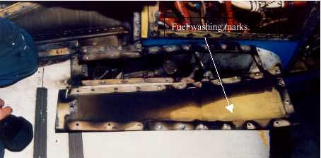
The area at the rear of the right-wing equipment bay, through which the inverter cooling air was drawn, was the most heat-affected area of the bay. Some of the ETFE wiring insulation in this area was completely burnt away. The forward end of the bay, in the area of the other fuel leak, exhibited some wiring damage and medium to heavy sooting. In this area there was also evidence of 'washing' of fuel against the upper access panel (See Fig 6). The wiring and components that were immediately adjacent to the fuel leak in the area were not as heat affected as in other parts of the zone.
View of upper surface of right wing, showing fuel 'washing' on upper access panel
A typical hydrocarbon fuelled ground fire would burn at a temperature in the range of 870 0 C to 1093 oC. An inflight fire, with the added oxygen, would burn in excess of 1093 oC, often up to 1371 oC and higher. The aluminium alloy in aircraft becomes plastic at 454 o C and melts at about 677 oC, while the extruded ETFE insulation on the electrical wiring, melts at approximately 300 o C. The cable ties are made from either Teflon or nylon and have a similar melting point of 280 o C to 300 oC
Engine isolation and fire extinguishing system The aircraft was equipped with an engine isolation and fire extinguishing system that was activated by the operation of a fire emergency tee handle. The operation of the fire handle cuts fuel to the selected engine and arms the engine fire extinguisher bottle. The pilot can then discharge the fire extinguisher by depressing an instrument panel mounted switch.
During the shutdown of the aircraft prior to passenger evacuation, the flight crew had activated the engine fire handles and attempted to discharge the right engine fire bottle several times. The fire bottle, however, had not discharged and the fire wall fuel shut-off valve had not closed. An inspection of these emergency systems revealed that the components had not operated because of fire damage that had occurred to the electrical wiring to these components. The right side firewall shut-off valve circuit breaker was found to have tripped during the incident. Regardless, the operation of the system would not have had any effect in this instance, due to the fire being in an area outside the engine fire zone.
Following an inspection of the manufacturer's maintenance procedures for the aircraft type, it was discovered that there was no procedure for determining the serviceability of the fire bottle activation system that ensured there was sufficient voltage at the fire bottle electrical connection to activate the bottle. This has been brought to the attention of the aircraft manufacturer.
During the approach to land the tower controller advised the crew of the BAe146 that the aircraft appeared to be trailing smoke. The crew responded that there was no cockpit indication of fire, but asked the controller "to keep an eye on it". The rescue firefighting service was then alerted and placed on local standby.
During the landing roll a fire service officer advised that there was smoke in the area of the auxiliary power unit (APU) jet pipe but that no flame was evident. The aircraft was taxied in normally, after which the passengers were disembarked through the forward entry door. During the disembarkation, flames were observed from the APU jet pipe and were quickly extinquished.
The crew advised that the APU had "overtemped and hung" during the startup sequence. It was soon after this time that the Tower controller reported smoke behind the aircraft. The APU was shut down and the integrity of the APU fire warning system confirmed. There was no indication of smoke in the cockpit or cabin.
Initial examination revealed a significant internal failure of the APU turbine. The subsequent fire was contained within the core of the APU and there was no external damage to the engine or to the air conditioning bay. The APU was removed from service for detailed bulk strip examination.
As a result of this investigation the operator advised that the following actions were taken:
All maintenance personnel were made aware of approved company maintenance procedures relating to APU's.
Company personnel were instructed on the proper reporting procedures to ensure prevention of any further breakdown in the reporting chain.
As a result of this investigation the operator advised the following:
The role and responsibility of personnel posted at reduced or single-engineer bases are to be clarified and reviewed.
Arrangements for the ongoing supervision of personnel posted at reduced or single-engineer bases are to be reviewed.
The occurrence is to be reviewed with respect to the company's standard crew resource management policy.
The role and responsibility of ground personnel are to be reviewed and clarified with respect to non-normal and emergency situations.
Analysis
It is likely that during the time the engineer was away from the APU, with the oil dolly still connected, the faulty spool valve in the oil delivery line permitted the oil to continue to flow into the APU, resulting in an overfilled condition with excess oil draining into the tailpipe. The APU then surged and automatically shut down. The surge was probably caused by some of the excess oil within the APU escaping through the bearings and entering into the combustion chamber, where it was ignited. This would have resulted in a rapid increase in the exhaust gas temperature. Flame from the combustion would then have "torched" through the turbine stage into the tailpipe, where it ignited the overflow oil that had drained into the tailpipe.
The pilot in command was initially provided inadequate information regarding the APU problem. He was aware that the APU had shut down, and was informed that there was an APU fire. However, this was not confirmed by an ECAM message due to the location of the fire in the tailpipe. This series of events was an unusual situation and did not fit with the pilot in command's expectations of an APU fire. Had he been properly informed of the circumstances of the fire, it is unlikely that he would have considered it necessary to inspect the APU. Consequently, he would have been able to more rapidly respond to ensure the safety of the passengers and crew.
The operator was unable to immediately follow its post-occurrence investigation procedures due to delayed and incomplete reporting of the circumstances of the occurrence.
Summary
On 19 February 1999, while on the tarmac at Townsville with the auxiliary power unit (APU) operating, the crew of A320 Airbus VH-HYT observed an advisory message for "oil quantity below 1/4" on the electronic centralised aircraft monitoring (ECAM) cockpit display. The limitations section of the operator's A320 Operating Manual stated that the minimum before start APU oil quantity was 1/4. However, it also noted that with the ECAM low oil level message displayed, the APU should be considered unserviceable until an engineering inspection was conducted. This included a check of the APU oil level and inspection of the APU compartment and air intake for oil contamination.
The pilot in command notified the operator's Townsville maintenance engineer of the ECAM APU oil quantity message. The operator's procedure in response to a low APU oil quantity ECAM advisory message required that the APU be inspected for gross oil leaks and that the aircraft maintenance log APU oil servicing records be reviewed to determine oil consumption. However, because the APU bay was a controlled fire zone, the operator's maintenance procedures specified that the APU access door not be opened while the unit was operating.
The engineer opened the APU bay access door and inspected the operating APU for oil leaks. He then returned to the cockpit, where he consulted the aircraft maintenance log to review the APU oil servicing records. Noting that oil had not recently been added to the APU, the engineer advised the pilot in command that he would replenish the APU oil.
Passengers were already on board for the flight to Brisbane. Because of the prevailing hot and humid conditions, the engineer decided that, for reasons of passenger comfort, he would leave the APU running while he replenished the oil. This decision to add oil to the APU while it remained operating was in violation of the operator's standard policy and procedures, which stated that replenishment of APU oil may only be carried out while the unit is not operating.
The engineer connected the oil supply line from a mobile oil dolly to the operating APU. The oil dolly was equipped with a pressurised supply tank, with delivery of oil from the tank being controlled by a hand-operated spool valve in the oil delivery line. The engineer had determined that 1 L of oil should be added to the APU, and he calculated that it would take 15 seconds to deliver that quantity from the oil dolly into the APU. After the oil had been added, the engineer returned to the cockpit to observe whether the ECAM advisory message had extinguished, leaving the APU access hatch open and the oil delivery line still connected to the operating APU. The ECAM advisory remained illuminated, so the engineer returned to the APU bay. As he was climbing onto the workstand, a fire broke out in the APU tailpipe and the APU shut down.
The surface movement controller in the control tower observed fire and smoke coming from the tail of HYT. He sounded the crash alarm and radioed HYT on the surface movement control frequency, but there was no response. Three fire trucks responded immediately and parked in a fanned position around the aircraft's tail, with one truck being parked under the APU exhaust. Two firemen climbed onto the top of that truck to better observe the source of the fire and to determine the appropriate fire-fighting measures to be employed.
The crew had been conducting pre-flight checks when they noticed the APU shutdown. At the same time, they heard the sirens from the fire trucks, and a customer service officer entered the cockpit and notified the crew that the APU was on fire. However, the engineer also entered the cockpit and stated that the fire was under control, but he did not inform the pilot in command that the fire was located in the APU tailpipe and not in the APU bay.
HYT was equipped with a fire and overheat detection system located in the APU compartment. The system was designed to provide for automatic APU shutdown and agent discharge in the event of fire or overheat in the APU compartment while the aircraft was on the ground. A fire warning light was fitted to the overhead panel in the cockpit to alert the crew in the event of an APU fire. However, because the fire was located in the APU tailpipe, it did not activate the APU fire detection system and consequently there was no fire warning. After being advised that an APU fire had occurred, the pilot in command elected to leave the aircraft to obtain further information about the nature of the problem and its effect on the safety of the aircraft. Before leaving the cockpit, he made a public address to the passengers to advise that the aircraft had experienced a problem with its air-conditioning system, and that this would delay the aircraft's departure.
The pilot in command then left HYT through the left forward cabin door (L1) but did not brief the cabin manager, who was stationed at L1, about the nature of the problem. The cabin manager was therefore unable to plan for the possible evacuation of passengers from the aircraft. The pilot in command proceeded to the rear of HYT, where one of the fire crew informed him that the fire was still burning. The fire crew were unaware that passengers were already on board and when the pilot in command asked if they wanted the passengers off the aircraft, the fire controller instructed the pilot in command to disembark the passengers immediately. However, no instruction was given regarding doors that were not to be used for the disembarkation.
The pilot in command then ran back and instructed the cabin manager stationed at door L1 to disembark the passengers. Up until that point, the only information that the cabin manager had been given about the fire was from the customer service officer when the officer had entered the aircraft to advise the pilots of the problem. None of the other flight attendants were aware of the situation until the order to disembark the passengers was given. All passengers and crew were then disembarked through both the front and rear entry doors on the left side of HYT.
The airport fire crew discharged three 5 kg carbon dioxide bottles into the APU exhaust and the fire was extinguished. When the fire controller determined that HYT was safe, he released it to the crew. The engineer conducted a damage inspection of the aircraft and it was dispatched with the APU inoperative.
On arrival at Brisbane, the pilot in command lodged a general flight report stating that HYT had sustained an APU tailpipe fire at Townsville. The report noted that there was no fire warning or ECAM display associated with the APU tailpipe fire. The same day, the engineer reported to the operator's Melbourne maintenance base that HYT had sustained an APU tailpipe fire. Neither of these reports mentioned that the APU oil had been replenished while the unit was operating.
On 4 March 1999, the engineer lodged an accident/injury report of the event with the operator, noting that an APU tailpipe fire had occurred. On 5 March 1999, BASI received an air safety incident report from the company concerning the occurrence and on 8 March 1999, BASI also received an air safety occurrence report from RAAF Townsville.
On 10 March 1999, the operator interviewed the engineer. During the interview, it was established for the first time that the APU oil had been replenished while the unit was operating. The engineer advised the operator that on 21 February 1999, he and another engineer had inspected the spool valve of the oil dolly. The inspection was conducted to determine if oil continued to flow from the delivery hose with the spool valve in the closed position. The inspection revealed that the spool valve was faulty and that it had probably been faulty at the time of the occurrence.
In preparing the aircraft for the next flight, the pilot turned on the valve for the medical oxygen system. Witnesses then heard a loud bang and gas escaping as the pilot was thrown clear of the aircraft, which caught fire and burned. The pilot received significant ear and chest injuries in the blast.
The Bureau recommends that the Civil Aviation Safety Authority: (i) conduct an audit of all emergency medical service oxygen-equipped aircraft to determine the equipment standards in Australian registered aircraft; (ii) issue design standards for emergency medical service oxygen equipment installations; (iii) issue maintenance requirements for emergency medical service oxygen equipment; (iv) provide surveillance requirements for emergency medical service oxygen equipment in the Aviation Safety Surveillance Program; (v) ensure flight crew are provided with appropriate instructions in the use of emergency medical service oxygen equipment in aircraft flight manuals or company operations manuals; and (vi) provide educational material to the aviation industry on the installation, operation and maintenance requirements of emergency medical service oxygen systems.'
At 0707 hours, on 4 July 1992, Boeing 727-277 aircraft VH-ANA took off from runway 01 at Brisbane Airport on a regular public transport flight to Sydney. As the landing gear was retracting, the crew heard a loud bang emanate from the rear of the aircraft This was followed by cockpit indications of a fire in, and a loss of thrust from, the no. 2 (centre) engine.
Ground witnesses saw large flames streaming from the rear of the aircraft. The crew shut down the engine, completed the engine-fire checklist, and flew a circuit for a landing on runway 01. During the landing roll, the crew were advised that there were still signs of fire around the centre engine, so a decision was taken by the aircraft captain to evacuate the aircraft. After clearing the runway and stopping the aircraft, the evacuation of passengers and crew was carried out from the two front doors and the forward left overwing exit.
During the evacuation, two passengers received minor injuries. The fire was extinguished quickly by airport fire personnel.
The investigation revealed that a fatigue failure had occurred in the first-stage compressor fan disc of the no. 2 engine leading to disruption of the engine. The fire resulted when a section of engine disc severed the main fuel line to the engine. Deficiencies were also revealed in the Brisbane Airport emergency plan and in some aspects of the training of rescue and firefighting personnel.
Occurrence summary
Investigation number
199202582
Occurrence date
04/07/1992
Location
Brisbane
State
Queensland
Report release date
15/07/1993
Report status
Final
Investigation type
Occurrence Investigation
Investigation status
Completed
Mode of transport
Aviation
Aviation occurrence category
Diversion/return, Engine failure or malfunction, Fire
The flight was arranged by the pilot with the Royal Federation
of Aero Clubs of Australia and was to bo conducted in accordance
with FAI rules governing a class of aeroplanes having piston
engines and weighing from 1000 kilograms to less than 1750
kilograms. An observer was appointed to monitor the attempt. He
witnessed the weighing of the aircraft and also installed a sealed
barograph which was intended to substantiate the actual altitude
reached.
The pilot was a flying instructor and charter pilot in the
employ of Rossair Pty. Ltd. and that company assigned the aircraft
for the attempt on the altitude record.
At approximately 0745 hours Central Standard Time on 20 January 1972, there was an in-flight fire in a Beech 65-80 Queenair aircraft, registered VH-CMI, which resulted in the separation of the starboard engine and the starboard outer wing. The aircraft subsequently struck the ground some seven miles south-west of Alice Springs Airport in the Northern Territory. At the time of the accident, the aircraft was engaged in operating a charter flight for the purpose of carrying passengers, mail and freight from Alice Springs to Ayers Rock. The aircraft was destroyed by fire and impact forces and the pilot and the six passengers were killed.
During a spray run, at a height of 20 to 30 feet, the engine suffered a complete loss of power. After manoeuvring to avoid obstructions the pilot attempted to land in a restricted but relatively flat area bordering a
gully. In the landing flare the left main undercarriage struck a small bank and was torn off. The aircraft continued in flight for 192 feet, touched down on the right wheel, swung slightly right and came to rest facing
90 degrees to the line of flight. The pilot turned the ignition and master switches off. As he vacated the
aircraft he noticed that thin smoke was coming from the master switch area and under the engine cowling, that
paint at the top right rear of the cowling had blistered and was "bubbling", and that the rotating beacon continued temperature. He returned to the aircraft and confirmed that the master switch was off. Some 10 minutes later flames broke out at the rear of the engine.
The aircraft departed Port Hedland and commenced to climb to a cruising altitude of 5,500 feet. When
it had climbed to approximately 3, 000 feet a loud bang from the engine area was heard, and a substantial
loss of engine power occurred. The pilot turned back towards the aerodrome and the cabin began to fill
with smoke but this cleared when the port window was opened. The pilot carried out various cockpit
checks but was unable to restore full power to the engine and he carried out a straight in approach and
landed on runway 32.
Subsequent examination revealed that the No. 5 cylinder head had failed, following the development of a
fatigue crack. Displacement of the cylinder head after failure broke a fuel injection line which led to a
fire in the engine cowling, and resulted in damage to engine components and cowlings and to lower
fuselage skin.