As the aircraft was nearing the end of the landing roll, the Tower Controller observed smoke briefly issuing from one of the wheel assemblies. The crew was alerted, and reported that a hot brake temperature warning was indicated on the flight deck. The smoke had not persisted, and the pilot in command elected to continue taxying to the terminal area, in order to allow a normal disembarkation of the passengers. He requested the Tower to monitor the situation. The Airport fire services were summoned and followed the aircraft. Another Tower Controller then reported that fire had broken out in the left maingear. The aircraft was halted and the pilot in command ordered an evacuation. The evacuation proceeded smoothly, but injuries resulted from the use of the escape slides. The fire crews rapidly extinguished the fire and assisted with the evacuation process. Investigation revealed that an electrical short circuit had occurred in a solenoid in the anti-skid system which controls the brakes on one of the left mainwheels. This led to the brakes on the affected wheel being applied continuously. The resulting overheating in turn led to the eventual disintegration of the brake disc and pads, and the outer covering of an hydraulic line caught fire. Considerable overheating of the tyre and wheel rim also took place. The crew had no direct communication with the fire crews on site, and were unaware of the extent of the fire. This had left the pilot in command with no alternative but to order the evacuation of the aircraft.
When approaching Lake Nash the pilot had selected the fuel boost pumps to low in accordance with the manufacturer's operating handbook. He started to smell fuel so he turned the pumps off. After landing he shut down and unloaded the appropriate freight. On start up he did not smell any fuel but, at about 40 knots on the takeoff run, the left wing tip exploded and the aircraft caught fire. The pilot brought the aircraft to a stop off the strip and evacuated the aircraft. He was unable to recover any of his documents before the aircraft was totally destroyed by fire. Examination by an engineer indicated that the fire may have started in the left wheel well area and that fuel vapour in the wing had exploded through the wing tip.
On 7 January 2010, the crew of a Convair 580 aircraft, registered VH-PDW, were conducting a training flight from Bankstown to Tamworth, New South Wales (NSW). While on descent to Tamworth, the crew noticed smoke emanating from below the instrument panel. Shortly after, the smoke intensified, and flames appeared. The flight crew declared an emergency and suppressed the flames using a portable fire extinguisher. The crew continued the descent, and the aircraft landed without further incident.
A subsequent engineering inspection revealed that a small amount of insulation material had become detached and fallen onto the right red instrument panel light rheostat and surrounding wires. The rheostat had developed a 'hot spot' and consequently, the insulation absorbed the heat and transferred it to the wires, which produced smoke and flames.
The operator has advised the ATSB that, as a result of this occurrence, it has implemented a number of safety actions, including:
all of the organisation's aircraft have been examined to ensure that there is sufficient clearance between the rheostats, insulation material and wires
any insulation material located in close proximity to a rheostat has been removed
a notice to crew was issued to emphasise the importance of recording defects in the maintenance log.
On 10 June 2009 at 1205 Universal Coordinated Time (UTC), an Airbus Industrie A330-202 aircraft, registered VH-EBF, departed Kansai International Airport, Osaka, Japan on a scheduled passenger transport service to the Gold Coast Airport, Qld., Australia with 182 passengers, 13 cabin crew and four flight crew on board.
At 1523, at approximately 427 km south-west of Guam, the flight crew noticed a burning rubber smell on the flight deck. At about that time, two caution messages were displayed to the crew identifying a fault in the right windshield heating. This was followed by a loud bang along with a flash of light, followed by smoke and fire from the bottom right corner of the right windshield. All flight crew donned oxygen masks, and a crew member used a BCF extinguisher to extinguish the fire.
The flight crew diverted the aircraft to Agana Airport, Guam, and reported that no other systems were affected by the fire. At 1614, the aircraft landed at Guam and there were no reported injuries to any of the passengers or crew.
------
Update: 24 March 2011
The Australian Transport Safety Bureau (ATSB) is finalising its investigation into the June 2009 in-flight fire event that occurred in the cockpit of an Airbus A330 aircraft (registered VH-EBF) during a scheduled passenger service between Osaka, Japan and Gold Coast Airport, Queensland, Australia.
As the preliminary report on this incident indicates, the ATSB has identified the source of the fire to have been an electrical fault within a terminal block located at the lower right corner of the cockpit right forward windshield. The terminal block served to direct electrical power into the windshield's heating circuitry; ensuring they remain clear and free of ice and fogging that may otherwise interfere with the pilots' outside visibility.
Terminal block failure
Under the oversight and support of the accredited representative from the French investigation agency (Bureau d'Enquetes et d'Analyses pour la securite de l'aviation civile, BEA), the damaged windshield terminal block was dismantled and examined in detail at the manufacturer's facilities in France. While the analysis of the technical findings will be presented in the final ATSB report, it has been ascertained that the terminal blocks of certain windshields produced between February 2007 and August 2008 were susceptible to overheating in a manner similar to that sustained during this occurrence.
Investigation status
The draft report on this investigation is nearing completion and distribution to directly involved parties for comment. A final report should be published during the second quarter of 2011. However, the following safety actions have already been initiated:
Aircraft operator
Following the occurrence affecting VH-EBF, the aircraft operator inspected all windshield terminal block fittings within the aircraft in its fleet. The inspection centred on identifying any evidence of thermal effects or localised heating that may be precursor indications of a similar overheating mechanism. No such evidence was observed during any of the inspections undertaken.
Aircraft manufacturer
In early 2010 the aircraft manufacturer initiated an ongoing retrofitting program to remove and replace all suspect aircraft windshields.
Summary
On 10 June 2009, the flight crew of a Jetstar Airways Airbus A330 aircraft, registered VH-EBF, flying from Osaka, Japan to Gold Coast, Queensland, observed flames at the base of the right main windshield. The fire had initiated from an electrical connection to the windshield heating system. The fire was extinguished by the flight crew and the flight diverted to Guam.
The ATSB investigation concluded that the overheat failure of the right windshield was related to the use of a polysulfide sealant (PR1829) within the body of the electrical connector terminal block. Use of that sealant had created conditions within the block which led to unintended electrical heating effects during operation of the windshield heating system. Consequentially, this had developed into the thermal breakdown of the sealant and the initiation of a localised fire.
Subsequent to the occurrence involving VH-EBF, similar windshield overheating events in other Airbus A330 and A320 aircraft were reported. The aircraft manufacturer's technical examination of those windshields concluded that contact between the braided wires within the terminal block, as well as the unintended migration of the PR1829 sealant had probably combined to trigger the reported events.
Safety action from the aircraft manufacturer included a program to identify and replace all windshields that had been produced using the PR1829 polysulfide sealant within the electrical connector terminal block assembly. That program was initiated in early 2010 and extended to the replacement of approximately 1,500 units within the world-wide Airbus fleet. The ATSB have been advised that due to limited fleet-wide completion of the windshield replacement program, the European Aviation Safety Authority (EASA) is considering the implementation of an Airworthiness Directive (AD) that will require all European operators of applicable Airbus aircraft to comply with the Airbus windshield replacement program. The ATSB were also advised that the windshield replacement program was completed across the Qantas Group of applicable aircraft in April 2011, and that windshields fitted to other Australian operated A330 aircraft are not affected by the replacement program.
On 21 August 2005, the Aircraft and Railway Accidents Investigation Commission (ARAIC) of Japan notified the Australian Transport Safety Bureau (ATSB) of an air safety occurrence involving an Australian-registered and -operated aircraft, which occurred earlier that day at Kansai International Airport. The ATSB appointed an accredited representative to participate in the investigation into the occurrence, in accordance with clause 5.18 1 and 5.23 2 of Annex 13 to the Convention on International Civil Aviation. To protect the information supplied by ARAIC to the ATSB and investigative work undertake to assist the ARAIC, the ATSB initiated an investigation under the Transport Safety Investigation Act 2003. The report presented below was prepared principally from information supplied to the ATSB.
On 20 August 2005, an A330 aircraft, registered VH-QPE, was being operated on a scheduled passenger service from Narita International Airport, Japan, to Perth International Airport, Western Australia. The aircraft departed Narita at about 1238 Coordinated Universal Time, with 13 crew and 181 passengers on board. At 1405, while the aircraft was in cruise, the crew received an Electronic Centralized Aircraft Monitoring (ECAM) warning indicating that there was smoke in the forward cargo hold. The crew activated the fire extinguishing system, and diverted the aircraft to Kansai International Airport, Japan. At 1551, immediately after the aircraft had landed, emergency services personnel reported that there appeared to be smoke in the vicinity of the nose landing gear. The flight crew initiated an emergency evacuation of the aircraft. During the evacuation, one passenger sustained serious injuries and eight passengers sustained minor injuries. In accordance with its obligations under Annex 13 to the Convention on International Civil Aviation, the ARAIC initiated an investigation of the factors that contributed to the development of the accident.
The ARAIC is the independent Japanese government authority responsible for the safety investigation of aviation accidents and incidents in Japan. The Australian accredited representative's role in the investigation has been to provide the ARAIC with information about the aircraft and its operation, and analyse recorded information.
The ARAIC will publish the final report related to the investigation of this occurrence.
The State of Registry, the State of the Operator, the State of Design and the State of Manufacture shall be entitled to appoint an accredited representative to participate in the investigation.
Any States which on request provides information, facilities or experts to the State conducting the investigation shall be entitled to appoint an accredited representative to participate in the investigation.
Summary
On 21 August 2005, the Aircraft and Railway Accidents Investigation Commission (ARAIC) of Japan notified the Australian Transport Safety Bureau (ATSB) of an air safety occurrence involving an Australian-registered and operated aircraft, which occurred earlier that day at Kansai International Airport. The ATSB appointed an accredited representative to participate in the investigation into the occurrence, in accordance with Annex 13 to the Convention on International Civil Aviation.
On 20 August 2005, an A330 aircraft, registered VH-QPE, was being operated on a scheduled passenger service from Narita International Airport, Japan, to Perth International Airport, Western Australia. The aircraft departed Narita at about 1238 Coordinated Universal Time, with 13 crew and 181 passengers on board. At 1405, while the aircraft was in cruise, the crew received an Electronic Centralized Aircraft Monitoring (ECAM) warning indicating that there was smoke in the forward cargo hold. The crew activated the fire extinguishing system, and diverted the aircraft to Kansai International Airport, Japan. At 1551, immediately after the aircraft had landed, emergency services personnel reported that there appeared to be smoke in the vicinity of the nose landing gear. The flight crew initiated an emergency evacuation of the aircraft. During the evacuation, one passenger sustained serious injuries, and eight passengers sustained minor injuries.
The ARAIC is the independent Japanese government authority responsible for the safety investigation of aviation accidents and incidents in Japan. The ARAIC will publish the final report related to the investigation of this occurrence.
On 17 May 2005, a Boeing 717-200, registered VH-VQI, was scheduled to operate a regular public transport flight from Hobart to Sydney, departing at 0600 Eastern Standard Time. During the starting of the right engine, the aircraft dispatcher informed the flight crew that there was smoke and sparks shooting from the right engine and advised 'we'll have to get everyone off'. The pilot in command called for an emergency evacuation without initiating the Passenger Evacuation Checklist. As a result, the wing flaps were not set to the extended position and the tail section of the aircraft was dark without emergency lighting while passengers were exiting the aircraft. All three of the floor level exits were opened by cabin crew. The forward Door Right 1 escape slide fell to the ground uninflated when the door was opened.
A number of ground personnel ran to the front of the aircraft and helped 22 passengers off the forward Door Left 1 slide and directed them towards the terminal. Four passengers exited by the Door 2 slide at the rear of the aircraft and ran into the middle of the apron. The overwing exits were not opened. The aircraft's dispatcher had not received any education in emergency communications with flight crew nor aircraft evacuations at the terminal. The flight crew were engaged in conversations not confined to the engine start process or other operational matters during both engine start sequences until the problem with the right engine was first mentioned by the dispatcher. The reported smoke and sparks was a result of the right engine air turbine starter failing during the engine start sequence.
On 2 July 2003, the Boeing 747-438 aircraft, registered VH-OJU, operating on a scheduled flight from Singapore, arrived at Sydney at 0511 Eastern Standard Time, during the airport's curfew period. There was a tailwind of around 12 knots when the aircraft landed. The pilot flying selected auto brake setting three and idle reverse thrust in accordance with the curfew requirement. However, during the landing roll the reverse thrust was inadvertently de-selected.
On arrival at the terminal, the pilot in command (PIC) observed a BRAKE TEMP advisory message and notified the ground engineers. At that point, a fire ignited on the right wing landing gear. The flight crew were advised and the PIC ordered an evacuation of the aircraft. On receiving the evacuation announcement, the cabin crew commenced the evacuation drill deploying the aircraft's escape slides. The upper deck left (UDL) door and doors 2 left (L2) and 4 right (R4) escape slides, did not deploy. During the evacuation, the over-wing slide at door right 3 (R3) deflated while in use. As a result of the evacuation, one flight crew member and three passengers were seriously injured. Some passengers evacuated down the slides with their cabin baggage.
During the accident, an additional two brake fires ignited on the right body landing gear, one of which was extinguished by the Aerodrome Rescue and Fire Fighting Service (ARFFS). A subsequent inspection found that the aircraft's landing gear contained an excessive amount of grease with the presence of inappropriate grease on all of the landing gear axles. The three brake units that had caught fire were found to be serviceable but in a worn condition.
The investigation determined that slide R3 did not have any pre-existing defects that contributed to its failure. The nature of the failure was found to be overload of the fabric fibres during the evacuation. The inappropriate grease found on the landing gear axles was general purpose grease used on other components of the landing gear. The time and point of its application to the aircraft axles could not be determined.
The investigation found deficiencies in the operator's maintenance, flight crew and cabin crew procedures. As a result, the operator has issued maintenance memos to its engineering staff clarifying aircraft landing gear lubrication procedures, amended its Aircrew Emergency Procedures Manual, and reviewed cabin crew and flight crew emergency procedures.
As a result of this investigation, the ATSB is issuing safety recommendations to the operator and the Civil Aviation Safety Authority concerning the use of over-wing slides during known brake fires.
As a result of this incident the following local safety actions have been carried out.
Aircraft manufacturer
The manufacturer issued alert service bulletin SB747-21A2427, directing the inspection and corrective routing of the electrical wire loom to the boost fan.
Operator
The operator conducted a fleet inspection of the fan wiring for condition and routing and has undertaken to pay particular attention to the balancing of the boost fan assembly during overhaul. The incorporation of SB747-21A2427 on their fleet was scheduled for commencement from June 2003.
Technical Analysis Report
Technical Analysis Report: Boeing Commercial Aircraft Group, 747-436, G-BNLK
1. FACTUAL INFORMATION
1.1. Examination brief
The disassembled components of an electric air-cooling fan were received by the ATSB Technical Analysis unit for examination and analysis of the damaged fan impeller. The fan unit had been fitted to a Boeing 747 aircraft (registration G-BNLK) to provide forced air circulation for a forward galley chiller unit. During the early stages of a flight on 10 August 2002, a small fire developed in the forward cargo compartment adjacent to this unit. Physical and recorded evidence suggested the fire had initiated from electrical arcing that was a result of a wiring short-circuit near the fan terminal housing.
1.2. Samples received
Data plates affixed to the fan housing identified the unit as a three-phase unit (part number 73259E, serial number 3676), manufactured by Sunstrand (San Diego, California) in 1994. The fan was an axial flow design, with a single bell-shaped impeller manufactured from a moulded resin material. The motor and fan outlet guide vane assembly shared an integral housing which also carried the (damaged) electrical terminal housing. The motor was a brushless (induction) design, with the armature supported on sealed rolling element bearings. Surrounding the impeller was an aluminium shroud, which formed the fan intake and also provided for the mounting and support of the unit and its associated ducting.
1.3. Visual examination
1.3.1. Impeller
The impeller unit had been effectively 'cobbed', with all eleven blades fractured at or immediately adjacent to the impeller hub. The uneven, irregular nature of the fractures suggested the failure occurred as a cascading fragmentation event, with multiple sections of blade breaking away and striking others, causing further break-up. A study of all fracture surfaces failed to identify any evidence of pre-existing defects or cracking that may have precipitated the initial blade failure, nor was any indication found of unusual hard-object impact damage that may have suggested foreign object ingestion. There was some evidence however that suggested early damage to the impeller blade forward corners - many blades showed breakage of a curved lip of material from the corners in a manner that suggested possible contact with the fan shroud.
The inside surfaces of the impeller body carried a heavy coating of a powdery brown dust, which was also evident inside the armature core and around the end of the motor housing. This material was loose and easily wiped away by hand and a sample was taken for later qualitative chemical analysis.
1.3.2. Fan shroud
Produced as a machined die-casting from an aluminium alloy, the fan shroud encased the full impeller length and showed no evidence of having failed to fully contain the fractured impeller blades. Around the blade tip path, the shroud internal surfaces showed several circumferential wear bands that indicated significant tip interference. These were most clearly defined at the forward and rear limits of the blade path. Random indentation and scratching damage was noted around the shroud 'throat' region - this was consistent with the effect of multiple fragment impacts produced by the failing impeller blades. No specific evidence of hard-object impact damage was found across the blade path. Dark, waxy stains produced by an unidentified liquid draining through the fan shroud were noted at the low-point of the assembly and a series of tide-marks were formed on the front face of the shroud as the liquid had accumulated and later drained away.
1.3.3. Fan motor and housing
Being a brushless three-phase induction motor, the unit was comparatively simple in construction, with a star-wound stator containing a compact cage-type armature. Internal inspection found evidence of rub and erosion of the iron stator former over the innermost twenty millimetres of the stator length, however the armature did not reflect this and showed no evidence of operational damage. Several areas where material had been removed by bevelling the core corners were evidence that the armature had been re-balanced at some time following original manufacture. Both armature shaft bearings rotated smoothly by hand and showed no notable indications of distress or abnormal operation. The rear armature bearing housing contained particulate debris that appeared to be the fine brown dust mixed with lubricant lost from the bearing unit. The contact points of the leaf spring and the housing bottom showed light fretting damage, with some evidence of rotation also noted.
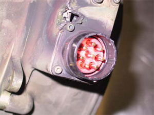
The fan motor electrical supply was routed behind the outlet guide vanes and terminated in an external housing fitted with an eight-pole connector. A localised area of heavy electrical arcing was clearly evident adjacent to the connector and had resulted in the melting and loss of around ten to fifteen millimetres of material in a v-shaped notch from both the front and side faces of the connector housing (figure 15). The metal loss had exposed some of the internal wiring and had produced an appreciable level of heating around the contact area, as evident from the tinting of the surrounding surfaces.
1.4. Dust analysis
The sample of brown dust recovered from the underside of the impeller body was qualitatively analysed using energy-dispersive x-ray spectroscopy techniques under the scanning electron microscope. The results of this test work showed the material to be comprised primarily of an iron-oxide compound, with traces of chromium, aluminium and silicon.
2. ANALYSIS
2.1. Impeller failure
All of the failed impeller blades exhibited brittle overload fractures. No evidence of material flaws, cracks or other pre-existing damage was shown by the blade stubs, however this was not conclusive, given the opportunity was not available to examine all of the blade remnants. Resin materials such as that used to manufacture the impeller have an inherent lack of ductility and as such, are prone to cracking and fracture under impact or elevated stress conditions. While no direct evidence was found to suggest the ingestion of foreign object/s, the damage sustained was not unlike that expected from such an event, and thus this possibility cannot be discounted.
2.2. Motor damage
The abrasion exhibited by the inner sections of the stator assembly was believed to be evidence of armature contact, presumably caused by the failure and collapse of the end bearing unit. The dust under the fan impeller was believed to be an accumulation of wear products from this contact - both the stator former and the armature core were ferrous alloys, while the remainder of the motor and fan assembly was predominantly aluminium based materials. Given that the installed armature showed no indication of stator contact and the end bearing was sound, it was concluded that the stator damage was a product of a previous failure that had been repaired by replacement of the armature and the re-use of the remaining components, including the impeller.
The collapse and failure of an armature shaft bearing and the shaft misalignment that results would be expected to alter the impeller - shroud clearances, with a risk of contact between the shroud and the impeller blade tips if the misalignment became severe enough. Impeller blade tip contact, if it did not produce immediate blade breakage, may produce latent cracking damage that could lead to later blade failures if not detected. While there was no evidence found to suggest that pre-existing damage of this nature existed, the possibility remained that this damage had been sustained given the evidence of the rear bearing failure and the contact marks inside the fan shroud.
2.3. Vibration
Rotary equipment such as the cooling fan relies upon accurate dynamic balancing to minimise the vibration induced during operation. Events such as the impeller failure will disrupt the balance of the assembly and can lead to significantly increased vibration levels. Wiring or piping that is installed against or in contact with the vibrating equipment may sustain fretting or erosion damage if the external protection or insulation has not safeguarded against this event.
3. CONCLUSIONS
3.1. Findings
The cooling fan impeller had sustained gross breakage of all blades at or adjacent to the body of the impeller.
All fractures were brittle in nature and showed no evidence of pre-existing defects.
No evidence of foreign object damage was found.
The fracture profiles of some blades suggested preferential tip breakage before the complete blade failure.
The fan motor showed evidence of a previous rear bearing failure that had produced contact and wear between the armature and the stator. The armature had subsequently been replaced, however the stator and other motor components remained in service.
The previous bearing failure may have allowed operating contact between the impeller blade tips and the fan shroud. This contact may have produced blade cracking which predisposed the impeller to failure in the manner observed.
After failure, the fan impeller would have presented a significant unbalanced load to the fan.
Significant Factors
Worn bearings led to impeller and shroud rubbing, weakening the blade tips.
The fan blade tips failed, creating an out of balance condition and vibration.
Chiller boost fan vibration resulted in the wires chafing and electrical short circuit initiating the fire.
The trip free capability of the circuit breaker in the chiller boost fan electrical circuit prevented rapid electrical isolation.
Factual Information
History of the flight
Shortly after take-off from runway 34L at Sydney, the flight crew of the Boeing 747-400 aircraft received a forward cargo compartment fire warning on the Engine Indicating and Crew Alerting System (EICAS). On receiving the warning message the crew actioned the appropriate checklist, activated the fire suppression system and transmitted a MAYDAY. At the same time, flight attendants noticed a fine mist and the smell of smoke in the passenger cabin. The crew then returned the aircraft to Sydney, where an uneventful overweight landing was conducted.
Prior to landing, the EICAS fire warning message ceased. This indicated that the aircraft fire suppression system may have successfully extinguished any fire, however the cabin fumes were still evident. After landing, the flight crew stopped the aircraft on the runway where emergency services came to their assistance. After confirming with the flight crew that the fire warning message was no longer present, the emergency services assessed the aircraft from the ground, then allowed the passengers and cabin crew to disembark to a safe distance via mobile stairs positioned at the aircraft's front left door. Once the passengers and cabin crew were clear of the aircraft, the emergency services opened the forward cargo door.
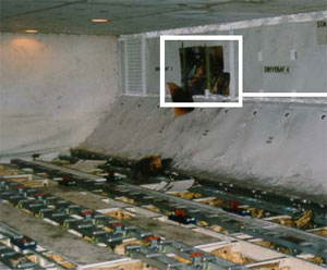
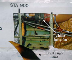
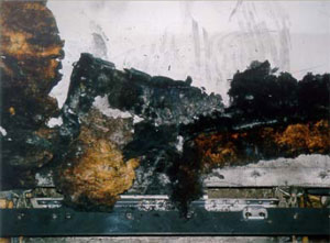
A hot spot was detected on the left side of the forward cargo bay at body station STA900, where the side wall lining was found to be heat affected. Removal of the lining revealed burned insulation blanket material, discolouration of the aircraft skin and burned/broken electrical wires that powered the forward galley chiller boost fan situated in the area (see Fig 1). As the fire was no longer evident, ground engineers isolated the chiller boost fan electrical circuit and towed the aircraft clear of the runway.
FIGURE 1: Forward cargo bay with expanded view of chiller boost fan location
Aircraft structural damage
Non-destructive testing to check for cracking and conductivity of the aircraft skin adjacent to the affected area was carried out. No cracks were detected, however the conductivity test revealed three locations where the skin had been substantially affected by heat (see Fig 2). The most severely affected area required a temporary skin repair before the aircraft could be flown back to the operator's maintenance facility in the United Kingdom, where the heat-affected aircraft skin was replaced.
FIGURE 2: Heat affected areas
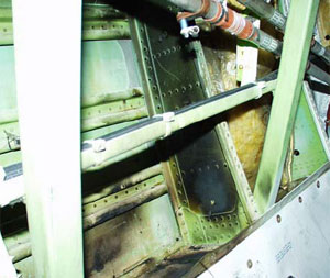
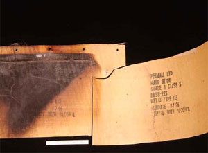
Sidewall lining and insulation blankets
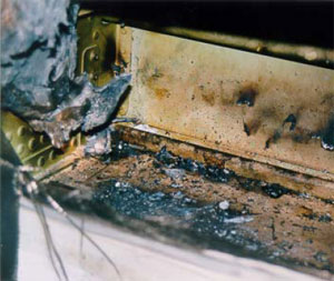
The fibreglass sidewall lining between STA880 to STA900 was visibly heat damaged with discolouration observed on the side facing into the cargo compartment. Inspection of the reverse side revealed burned layers of fibreglass confined to a localised area approximately 30cm x 45cm (see Fig. 3). The insulation blankets that lined the aircraft skin were made of a fibreglass core with a metallised TedlarTM film on one side and a MylarTM film on the other and had been subjected to localised heat and fire (see Fig. 4).
Samples of the sidewall lining and insulation blanket were sent to the United States of America, Federal Aviation Administration (FAA) technical centre and the aircraft manufacturer for analysis and testing.
FIGURE 3: Sidewall lining
FIGURE 4: Insulation blanket
The examinations determined that both the sidewall lining and insulation blanket samples complied with the appropriate material specifications for aircraft use.
The flammability testing, conducted by the FAA, on samples of the insulation blanket included a vertical Bunsen burner test, which was mandated in Federal Aviation Regulation FAR 25.853 - Appendix F. The samples tested met the requirements, but due to their limited size, the result was not conclusive as to the integrity of the entire blanket.
The aircraft manufacturer's tests revealed contamination on the insulation blanket samples. This contamination consisted of environmental dust, fibres and corrosion inhibiting compound. These contaminants were consistent with general contamination found during evaluations of other in-service insulation blankets and were considered to be normal.
The aircraft manufacturer's 'flame propagation cotton swab tests' found areas on the blanket samples that were self-extinguishing while other areas showed "flame propagation uncharacteristic of that expected for new insulation blankets". It was unknown whether contamination, in-service ageing, or heat exposure, or a combination of these, altered the blanket's flame propagation characteristics.
Boost fan system
A galley chiller boost fan system was installed in the aircraft to provide forced air circulation over the forward galley chiller units increasing their cooling efficiency. The system incorporated a vaneaxial-type three-phase fan, powered by the aircraft's number 3 alternating current electrical system. Control power was supplied by the aircraft's direct current electrical system, with operation being automatic on selection of the galley chillers to ON. Circuit protection was provided by a 20 ampere circuit breaker and a cargo fire cutoff relay.
Chiller boost fan
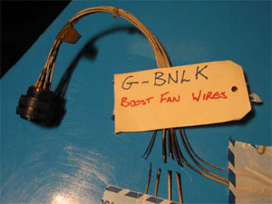
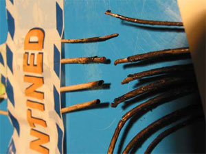
An inspection of the boost fan revealed a burn hole and sooting on its casing adjacent to the electrical terminal (see Fig. 5). The electrical wiring to the fan was found to have four of its seven wires broken, with all of the wires displaying sooting discolouration (see Fig's. 6 and 7). The soot marks corresponded to those on the fan casing and when positioned together, revealed that the wires had separated at a point adjacent to the corner of the electrical terminal. The failure of the wires produced electrical arcing, which melted the casing, resulting in the burn hole observed.
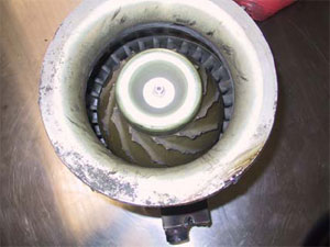
Further inspection found that all of the fan impeller blades had failed just above their roots (see Fig. 8). Neither the impeller nor the fan shroud showed signs of hard body impact damage.
FIGURE 5: Electrical terminal
FIGURE 6: Broken wires
FIGURE 7: Sooting evident
FIGURE 8: Fan impeller blades failed
Technical examination of the fan found that the impeller was made from a moulded resin material. There was no evidence of any pre-existing defects or cracking found on the blade fracture surfaces. However, a number of blades showed breakage of a curved lip of material from their forward corner. This condition was consistent with overload fatigue possibly due to the blade tips contacting the fan shroud. Such a condition may have occurred prior to the blades total failure. The inside surface of the impeller was coated with a brown powder, determined to be primarily iron oxide.
The aluminium alloy shroud contained several circumferential wear marks that were adjacent to the impeller blade path. Although there were random scratches, no evidence of gouging or penetration of the shroud skin was found.
Further disassembly of the fan revealed wear on the electrical motor stator, indicating that it had been subjected to armature rubbing. The armature did not display similar wear patterns. Rubbing of this nature usually occurs as a result of bearing failure or excessive wear, leading to armature oscillations. For the full technical report see Attachment 'A'
Chiller boost fan service history
The chiller boost fan entered service in 1994, with the last overhaul being in June 2000, after removal from service because of electrical failure. The maintenance records for that overhaul stated: "Unit noisy due worn bearings, all other parameters ok. Reported defect not confirmed. Disassembled, cleaned and inspected, bearings renewed, unit reassembled and tested to spec". The fan was then fitted to the incident aircraft on 2 August 2000. No subsequent maintenance was recorded.
Chiller boost fan circuit breaker and electrical relay
The installed circuit breaker was a 20 ampere three-phase, push-pull high performance, trip free type, designed for aircraft installations. It's design allowed for increased amperage through the circuit for a specific time before tripping (breaking the circuit) and was used in large motor load applications where the inrush current would trip a standard circuit breaker. The length of time taken to cause the circuit breaker to trip varied according to the current it received. The aircraft manufacturer advised that "At 385 per cent or 400 per cent [load rating], this breaker will trip between 2.3 to 10 seconds". This prevented aircraft electrical power surges from "nuisance" tripping of the circuit breaker and rendering the boost fan inoperative.
A number of tests were conducted on the circuit breaker, including a 'load withstanding test'. This required the controlled increase in current through the circuit breaker, with time to trip recorded. This test was conducted at 105 per cent, 140 per cent and 200 per cent values, as per the manufacturers test procedures.
The installed relay was a 25 ampere, electromagnetic, three pole, single throw, normally open type. This was also subjected to a number of tests including 'Coil resistance', 'Coil hold and drop voltage' and 'Voltage drop and switching test across all three phases'.
These tests were performed under the supervision of the United Kingdom Air Accident Investigation Branch. Both components were found to comply with their operational specifications, with no adverse mechanical or operational functions found during the testing. As a result, both components were considered to be serviceable.
Quick Access Recorder
The aircraft's Quick Access Recorder (QAR) data was analysed by the Australian Transport Safety Bureau with the following information retrieved.
During climb the number 3 alternating current system showed a momentary increase in load from a nominal 31 per cent to 54 per cent, which equated to an increase in current draw of 57 amperes.
Four seconds later, the load was again recorded and had returned to the nominal 30 percentage range, where it remained for the rest of the flight.
Approximately 1 minute later the QAR recorded a forward cargo fire.
Approximately 3 minutes later, the first cargo fire bottle low quantity message appeared, indicating that extinguishant had been discharged successfully.
Other recorded data received from the aircraft's central maintenance computer (CMC) confirmed the arming of the fire bottles approximately 2 minutes after the fire warning and the discharging of the last two fire bottles after the aircraft landed.
Cargo fire detection/extinguishing system
The aircraft incorporated two dual loop smoke detectors in each cargo compartment. Air from throughout the compartment was drawn through the detectors and sampled. In normal operation, both loops must sense smoke for a fire warning to be activated. If the system detects a loop fault during self-test at aircraft power on, it would reconfigure to a single loop operation.
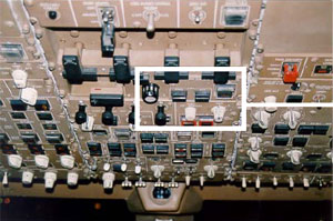
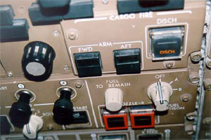
The cargo fire module located on the overhead instrument panel in the flight deck incorporated forward and aft compartment ARM buttons and a DISCH discharge button. On sensing smoke, the relevant ARM button, along with an EICAS message would be illuminated, alerting the crew of the fire. The crew must then push the ARM button in. This action disables electrical power to a number of circuits, including the galley chiller fan circuit. Extinguishing is then achieved by pressing the DISCH button (see Fig. 9).
FIGURE 9: Overhead instrument panel with expanded view of cargo fire panel
Four fire extinguisher bottles (A, B, C and D) service the cargo compartments, each having discharge lines to both the forward or aft compartments. On depression of the DISCH switch, bottles A and B discharge flooding the selected compartment with extinguishing agent. Bottles C and D are not discharged until 30 minutes later. If the aircraft reaches the ground before the 30 minutes are up, the bottles will discharge on touch down. The system was designed to give up to 180 minutes of discharge time.
As a result of this investigation, the Australian Transport Safety Bureau issues the following recommendations.
R20010133
The Australian Transport Safety Bureau recommends that the Civil Aviation Safety Authority, in conjunction with appropriate specialist organisations, develop and promulgate requirements that specify which fuel cylinder fittings are suitable for use in balloons, and suitable configurations for those fittings.
R20010134
The Australian Transport Safety Bureau recommends that the Civil Aviation Safety Authority ensure that balloon owners and operators identify and remove gas tank fittings that are not suitable for balloon operations.
Factual Information
Sequence of events
The balloon pilot and his two passengers were conducting a private flight as part of the Canberra balloon festival. The balloon's equipment included three aluminium liquefied petroleum gas (LPG) fuel cylinders, dual burners, three radios, a motorcycle-type lead-acid battery, an altimeter and a variometer. After completing a normal flight, the pilot prepared to land the balloon on an area of parkland. This area was relatively small, with large trees on the approach and a street and houses in the direction of flight. Following the touchdown, as the balloon envelope continued to travel, the basket gradually tipped over and the pilot pulled the ripline to deflate the envelope. At about that time, the occupants of the basket noticed a fireball in the basket and immediately evacuated. Witnesses described the flames as yellow. The pilot stated that he let go of the ripline and allowed the balloon to ascend, deciding that it was safer for the fuel cylinders to be in the air than on the ground surrounded by bystanders. Witnesses heard an explosion and saw an object fall from the remains of the basket. The fire continued to burn, and subsequently consumed the wicker basket and damaged the lower panels and skirt of the envelope. Debris from the balloon fell across three suburbs and damaged several houses. The remains of the balloon were subsequently found 1.6 km from the initial landing point.
The pilot of the balloon was wearing a hat, a short-sleeved cotton shirt, trousers, gloves and shoes. He sustained serious burns to his forearms, face and neck. The male passenger was wearing a woollen lumberjack-style long-sleeved shirt, jeans, gloves, boots, sunglasses and a hat. He sustained minor burns to his face and wrists and was the only occupant not admitted to hospital. The female passenger was wearing running shoes, three-quarter length pants, gloves and a long-sleeved top which did not tuck into the waistband of her pants. She sustained serious burns to her shins and stomach.
Wreckage examination
An examination of the wreckage of the balloon established that two aluminium fuel cylinders were each connected to one of the two burners. One tank was connected by both the vapour feed line and the liquid feed line, while the other was only connected by the vapour feed line. Both pilot-light valves were on, the cross-feed valve was off and both the liquid and vapour offtake valves on both fuel cylinders were on. It was also noted that a male connector fitting had broken off flush with the top of the threaded portion of the body of the corresponding fuel cylinder liquid offtake valve.
Further examination of the broken fitting showed that it had been partially fractured when the fire developed. The fracture was sufficiently large to allow the uncontrolled escape of LPG into the balloon's basket. The fracture surfaces indicated that the fire was no longer burning near the fracture at the time the fitting broke away completely. The fitting had fractured in a downward direction, and there was no evidence of fatigue or pre-existing defects.
One aluminium fuel cylinder was found along the debris trail between the initial landing site and the final location of the remains of the balloon. This cylinder had failed because of a single ductile rupture of the upper shell section, characterised by a large bulged area, outwardly turned fracture lips and extensive blackening and sooting around the rupture.
Pilot light usage
The balloon manufacturer's Flight Manual section 4.6 'Landing', stated that the pilot light should be turned off before touchdown. Some balloon pilots indicated that they sometimes left the pilot lights on for landing if they were certain that the balloon basket would not tip over, allowing them to conduct a go around if required. Once the pilot lights were turned off, if insufficient height was available to relight the pilot lights, a pilot would normally be prevented from conducting a go around before the balloon touched down.
Fuel cylinder fitting selection
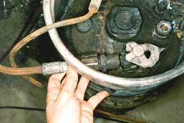
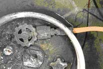
The broken fitting consisted of a Rego 8101P5 service valve coupled to a 7141M check connector. With this configuration, the assembly extended outside the fuel cylinder guard ring.
A comparison of the Rego 8101P5/7141M combination liquid offtake valve (left), and the Rego 8180 valve (right), and their relationship to the fuel cylinder guard ring
The balloon manufacturer's maintenance manual stated that "only factory supplied parts and materials are permitted to be used for repair or maintenance actions". The manufacturer advised that they previously supplied the Rego 8180 valve, but now supplied the BMV 344 handwheel-type liquid offtake valve in place of the Rego 8180 valve. The BMV valve was similar to the Rego 8180 valve. Balloon industry personnel suggested that while the Rego 8180 valve was the most widely used fitting, the Rego 8101P5/7141M combination was also relatively widely used in ballooning applications.
While the balloon manufacturer's documentation provided guidance regarding selection of fuel cylinder fittings, general practice among balloonists was for gas supply companies to replace, if required, fuel cylinder fittings during the mandatory 10-yearly cylinder inspection. Gas supply company personnel generally have extensive experience and knowledge regarding fuel cylinder maintenance, but they do not normally have much involvement in the aviation industry. They are not provided with detailed guidance regarding the appropriate selection and configuration for fuel cylinder fittings for aviation applications.
The investigation did not establish who had installed the Rego 8101P5/7141M combination liquid offtake valve.
Analysis
The intensity, size and rapid onset of the fire after the balloon landed suggested that a rapid, uncontrolled leak of LPG had occurred. The most likely source of the LPG leak was the fractured liquid offtake valve. It is also likely that the fracture occurred during the landing. The yellow flames reported by witnesses and the sooting of the ruptured cylinder suggest that the fire was fuel-rich, consistent with a high-volume gas or liquid fuel supply.
The position of the pilot light valves indicated that the pilot lights were on during the landing. Each of the radios or the battery could have provided an ignition source, but it is most likely that the pilot lights ignited the leaking LPG. Had the pilot lights been turned off prior to the landing, in accordance with the flight manual and standard ballooning practice, it is unlikely the leaking gas would have ignited.
The condition of the ruptured fuel cylinder indicated that it had failed as a result of flame impingement and subsequent softening of the aluminium shell. The explosion of the cylinder was therefore a consequence of the fire, rather than contributing to its development.
The length of the broken fitting provided significant leverage that would have required only a relatively small force to be applied before the fitting broke. There was also limited protection for the fitting because it extended significantly beyond the fuel cylinder guard ring. While the Rego 8101P5/7141M combination liquid offtake valve may have been appropriate for some applications, it was not appropriate for aviation. A firm or tip over landing could have resulted in the fitting being bumped or otherwise subjected to stress by occupants or equipment moving around.
The occupants of the balloon generally sustained burns to exposed areas of skin. Had they been wearing natural fibre clothing that more effectively covered these exposed areas, the extent of their burns would almost certainly have been reduced.
The investigation revealed that fuel cylinder fittings similar to the fitting that failed are relatively common in the ballooning industry in Australia. This suggests that the ballooning industry as a whole is not sufficiently aware of the safety implications of fittings extending significantly beyond the fuel cylinder guard ring.
The selection of suitable fittings for fuel cylinders in balloons requires the expertise of both the gas supply industry and the aviation industry. Both industries have specific requirements related to fuel cylinder fitting selection and configuration that may not be completely understood by the other.
Summary
The balloon pilot and his two passengers were conducting a private flight as part of the Canberra balloon festival. The balloon's equipment included three aluminium liquefied petroleum gas (LPG) fuel cylinders, dual burners, three radios, a motorcycle-type lead-acid battery, an altimeter and a variometer. After completing a normal flight, the pilot prepared to land the balloon on an area of parkland. This area was relatively small, with large trees on the approach and a street and houses in the direction of flight. Following the touchdown, as the balloon envelope continued to travel, the basket gradually tipped over and the pilot pulled the ripline to deflate the envelope. At about that time, the occupants of the basket noticed a fireball in the basket and immediately evacuated. Witnesses described the flames as yellow. The pilot stated that he let go of the ripline and allowed the balloon to ascend, deciding that it was safer for the fuel cylinders to be in the air than on the ground surrounded by bystanders. Witnesses heard an explosion and saw an object fall from the remains of the basket. The fire continued to burn, and subsequently consumed the wicker basket and damaged the lower panels and skirt of the envelope. Debris from the balloon fell across three suburbs and damaged several houses. The remains of the balloon were subsequently found 1.6 km from the initial landing point.
The pilot of the balloon was wearing a hat, a short-sleeved cotton shirt, trousers, gloves and shoes. He sustained serious burns to his forearms, face and neck. The male passenger was wearing a woollen lumberjack-style long-sleeved shirt, jeans, gloves, boots, sunglasses and a hat. He sustained minor burns to his face and wrists and was the only occupant not admitted to hospital. The female passenger was wearing running shoes, three-quarter length pants, gloves and a long-sleeved top which did not tuck into the waistband of her pants. She sustained serious burns to her shins and stomach.
The crew of the DHC-6-320 aircraft reported that during descent to Cairns they smelt smoke in the cockpit. They then noticed the battery load meter was at maximum discharge and the right generator light was illuminated. The left generator switch was moved to the OFF position, however, the generator remained on-line.
Subsequent in-flight inspection revealed that the smoke was coming from behind the right cabin roof panel, which had begun to melt and bubble. The pilot in command then contacted Cairns approach control reporting a fire in the cabin and the aircraft was cleared to track direct to Cairns. The co-pilot accessed the cabin fire extinguisher and extinguished the fire. At approximately 4NM from the airport, the co-pilot reported that the fire was an electrical fire and had been extinguished. After landing, the crew stopped the aircraft on the runway and shut down the right engine to allow the fire fighters access to the cabin. Following confirmation that the fire was extinguished the aircraft was taxied to the terminal.
Investigation by the owner's maintenance organisation found that the left reverse current relay had severe heat damage. Other components and wiring near the left reverse current relay were also heat damaged. The reverse current relay was disassembled by the maintenance organisation's engineers, but they were unable to determine the reason for the failure due to the severity of the heat damage.
The Bureau did not conduct an on-site investigation of this occurrence.
Occurrence summary
Investigation number
200001876
Occurrence date
20/05/2000
Location
28 km E Cairns, Aero.
State
Queensland
Report release date
24/08/2001
Report status
Final
Investigation type
Occurrence Investigation
Investigation status
Completed
Mode of transport
Aviation
Aviation occurrence category
Fire
Occurrence class
Incident
Highest injury level
None
Aircraft details
Manufacturer
De Havilland Canada/De Havilland Aircraft of Canada