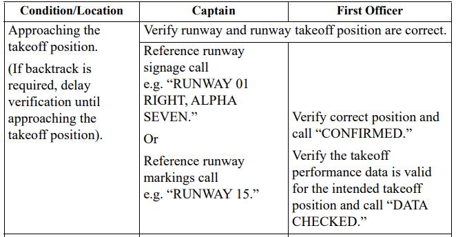
Collision with terrain

Partial power loss and collision with terrain involving Cessna 208, VH-UMV, near Barwon Heads Airport, Victoria, on 20 October 2023

Final report

Report release date: 14/03/2025

Investigation summary

What happened

On 20 October 2023 the pilot of a Cessna 208 aircraft, registered VH‑UMV and operated by Experience Co, was conducting parachute operations at Barwon Heads Airport, Victoria with 16 parachutists on board. Passing about 500 ft on climb, the pilot detected a partial power loss consistent with a previously‑encountered transient power reduction.

Expecting the power to return immediately, the pilot did not lower the aircraft’s nose to maintain airspeed. The airspeed continued to reduce until the stall warning horn sounded and, due to the low height, low engine power and low airspeed, the pilot attempted to conduct a forced landing. However, the aircraft collided with water before continuing onto the riverbank and ground for approximately 50 m before coming to rest.

The aircraft was substantially damaged, 6 of the parachutists received serious injuries, 8 sustained minor injuries, and 2 were uninjured. The pilot also sustained minor injuries.

What the ATSB found

The ATSB found that passing about 500 ft on climb, the power reduced likely due to abnormal activation of an engine torque and temperature limiting system. Expecting the power to return quickly and surge, and in preparation for turning off the system, the pilot moved the power lever aft to reduce the power setting and delayed lowering the aircraft’s nose to maintain airspeed, resulting in a stall warning and subsequent collision with water.

The ATSB also found that Experience Co’s engine power loss checklist instructed pilots to significantly reduce power in preparation for deactivating the engine limiting system, but did not specify a minimum safe height at which to do so. This increased the risk of a loss of control and/or ground collision. 

Further, the ATSB found that the operator's weight and balance calculation for the accident flight did not include the bench seating weight or moment, and the loadmaster did not load parachutists in positions used for the calculation of the centre of gravity, therefore, although it did not contribute to the accident, the weight and balance was inaccurate for the intended flight. Additionally, the software used to calculate aircraft weight and balance did not provide a warning if individual aircraft zones were overloaded.

Finally, the ATSB found that Experience Co did not ensure sport parachutists received essential safety information about emergency exits, restraints and brace position, prior to take-off. 

What has been done as a result

At the time of writing, Experience Co was re‑developing its sport skydivers safety video to include emergency procedures. Additionally, the following proactive safety actions have been taken:

  • A safety communique was developed and circulated at each drop zone reminding parachutists to be seated in accordance with their manifested location.
  • Chief instructors, drop zone safety officers and loadmasters were reminded of the loadmasters’ responsibilities to ensure parachutists were seated in accordance with the weight and balance calculation.
  • Skydive Operations Manual was amended to clarify the loadmasters’ responsibilities.
  • Additional training was provided for manifest staff.
  • A fleet-wide audit was undertaken to ensure all aircraft had accurate basic empty weight figures.
  • A prompt was added to the internal reporting software to confirm an entry has been made to the aircraft’s maintenance release when submitting a maintenance‑related internal safety report.
  • Briefings that cover essential safety information about emergency exits, restraints, and brace position, are now required annually by sport skydivers.
  • Additional pilot training relating to the single red line/torque and temperature limiter malfunctions has been developed and was scheduled to be delivered to all pilots.
  • Emergency exit signs in all aircraft were being assessed for compliance and effectiveness, and updated if necessary.
  • Engineering personnel have undertaken specialised TPE331 Powerplant and Systems training.
  • Information circulars were provided to company pilots about the proper defect reporting requirements using the aircraft maintenance release.
  • Experience Co was updating advice as to the altitude at which seatbelts must be worn.
  • Experience Co has developed Cessna 208 and Cessna 208B aircraft flight manual supplements, which outline the carriage of 17 parachutists and 21 parachutists respectively.
  • An additional support bracket has been designed to be fitted to the end of the bench seats in aircraft and will be installed once formally approved.
  • A new engine power loss checklist was developed in cooperation with the supplemental type certificate (STC) holder to be followed at or above 1,000 ft above ground level.

The Australian Parachute Federation (APF) has taken the following safety action:

  • The APF will ensure skydivers and pilots review their aircraft emergency procedures on a regular basis. Recommended topics are likely to include:
    • general safety around aircraft
    • hot loading
    • door activation
    • achieving correct restraint fitment
    • emergency landings
    • brace position
    • emergency exit altitudes and which parachute to use
    • communication during an emergency
    • for coastal operations, life jacket use in a ditching.
  • Each parachuting aircraft operator will conduct a thorough assessment of its aircraft to ensure single point restraints are properly installed, to prevent parachutists from moving outside their designated seating positions and to maintain the aircraft’s weight and balance.
  • The APF will review global data on the use of dual-point restraints to gather insights from other national parachuting organisations regarding their experiences with this system.
  • The APF examined aircraft flight manual wording of all aircraft currently conducting parachute operations in Australia to identify which aircraft would require a short-term CASA exemption to permit operations with the number of passengers onboard in excess of those able to occupy the normal seats under the type design. They identified 22 aircraft requiring an exemption, spanning 5 operators.
  • The APF added the following statement to the participant waiver form: ’parachuting aircraft are not operated to the same safety standards as a normal commercial passenger flight’.

Finally, the Civil Aviation Safety Authority advised that it is developing the following:

  • An exemption, for pilots or operators of parachuting aircraft who may be unable to comply with elements of the aircraft flight manual, is expected to be completed by mid‑2025.
    • CASA stated that it was satisfied that reasonable steps had been taken by the APF to ensure that a level of safety, commensurate with the risks involved in the parachuting activities in which participants engage, was provided to those participants in the interim while the exemption was being developed.
  • An amendment to the Civil Aviation Safety Regulations Part 21 Manual of Standards to specify the standards required for the modifications made to parachuting aircraft. This proposed action is expected to be finalised by the end of 2025.
  • Additional guidance to support aircraft owners and operators seeking to make an approved modification.

Safety message

The ATSB research report Avoidable Accidents No. 3 – Managing partial power loss after take-off in single-engine aircraft provides information to assist pilots to maintain aircraft control in the event of an emergency or abnormal situation after take-off. The report prescribed initial actions to be considered including:

  • Lower the nose to maintain the glide speed of the aircraft. If turning is conducted, keep in mind an increased bank angle will increase the stall speed of the aircraft.
  • Maintain glide speed and assess whether the aircraft is maintaining, gaining or losing height to gauge current aircraft performance.
  • Fly the aircraft to make a landing, given the aircraft’s height and performance, and the pre-planned routes for the scenario.

If time permits, moving the power lever through the full range may result in increased power available to climb and/or create the time to diagnose the issue.

The ATSB SafetyWatch highlights the broad safety concerns that come out of our investigation findings and from the occurrence data reported to us by industry.

SafetyWatch logo

One of the safety concerns is reducing the severity of injuries in accidents involving small aircraft. This incident highlights the importance of passengers being appropriately briefed on the brace position and use of emergency exits. It also illustrates the higher injury risk associated with the carriage of parachutists, due to the increased number of occupants and inferior restraints compared to being secured in a certified seat.


The occurrence

Early on the morning of 20 October 2023, the pilot of a Cessna 208 aircraft, operated by Experience Co and registered VH-UMV, refuelled and inspected the aircraft in preparation for parachuting operations from Barwon Heads Airport, Victoria. No defects, including any fuel debris or contaminants, were identified.

The pilot’s first flight of the day was to carry 16 sport parachutists for a parachute jump from 15,000 ft. At about 0750 local time, the parachutists boarded the aircraft. The pilot recalled that the conditions were CAVOK,[1] with a light wind from the north. They taxied the aircraft to runway 36 for a northern departure. 

A review of OzRunways[2] flight data, recorded at 5-second intervals, showed the aircraft commenced the take-off roll at 0757. The pilot reported moving the power lever forward until the engine reached 100% torque, and then reducing the power slightly during the take-off roll. Camera footage showed that the aircraft became airborne at 0757:22.

The pilot reported that, as the aircraft climbed and the airspeed increased, they retracted one stage of flap passing through 85 kt and another at about 95 kt. At 0757:47, climbing through about 400 ft, the aircraft reached its maximum recorded ground speed of 95 kt. The pilot reported that as the aircraft approached 500 ft above ground level and they reached for the flap lever to retract the last stage of flap, they heard a reduction in engine noise, and felt a deceleration. 

The pilot initially associated the loss of power with activation of the torque and temperature limiter (TTL) (see the section titled Torque and temperature limiter), which they had previously experienced in that aircraft. Consistent with the previous TTL activation, the pilot expected the power to quickly return, and reported reducing power slightly to prevent the engine surging[3] as power was restored.  

The reduction in engine power, combined with the climb pitch attitude, resulted in the airspeed reducing and activation of the stall warning horn. On hearing the stall warning, the pilot lowered the aircraft’s nose to reduce the angle of attack[4] and increase the airspeed. 

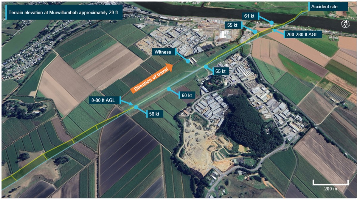
At 0757:57 the aircraft reached the highest recorded altitude of about 700 ft at 88 kt ground speed and, 5 seconds later, had descended to 600 ft and the ground speed reduced to 71 kt, then to 69 kt 5 seconds later. This flight path was consistent with video camera footage of the aircraft’s flight path (Figure 1). At 0758:08 the ADS-B[5] data recorded a descent rate of 3,520 ft/m passing an altitude of approximately 400 ft.

Figure 1: VH-UMV flight path captured by the airport camera
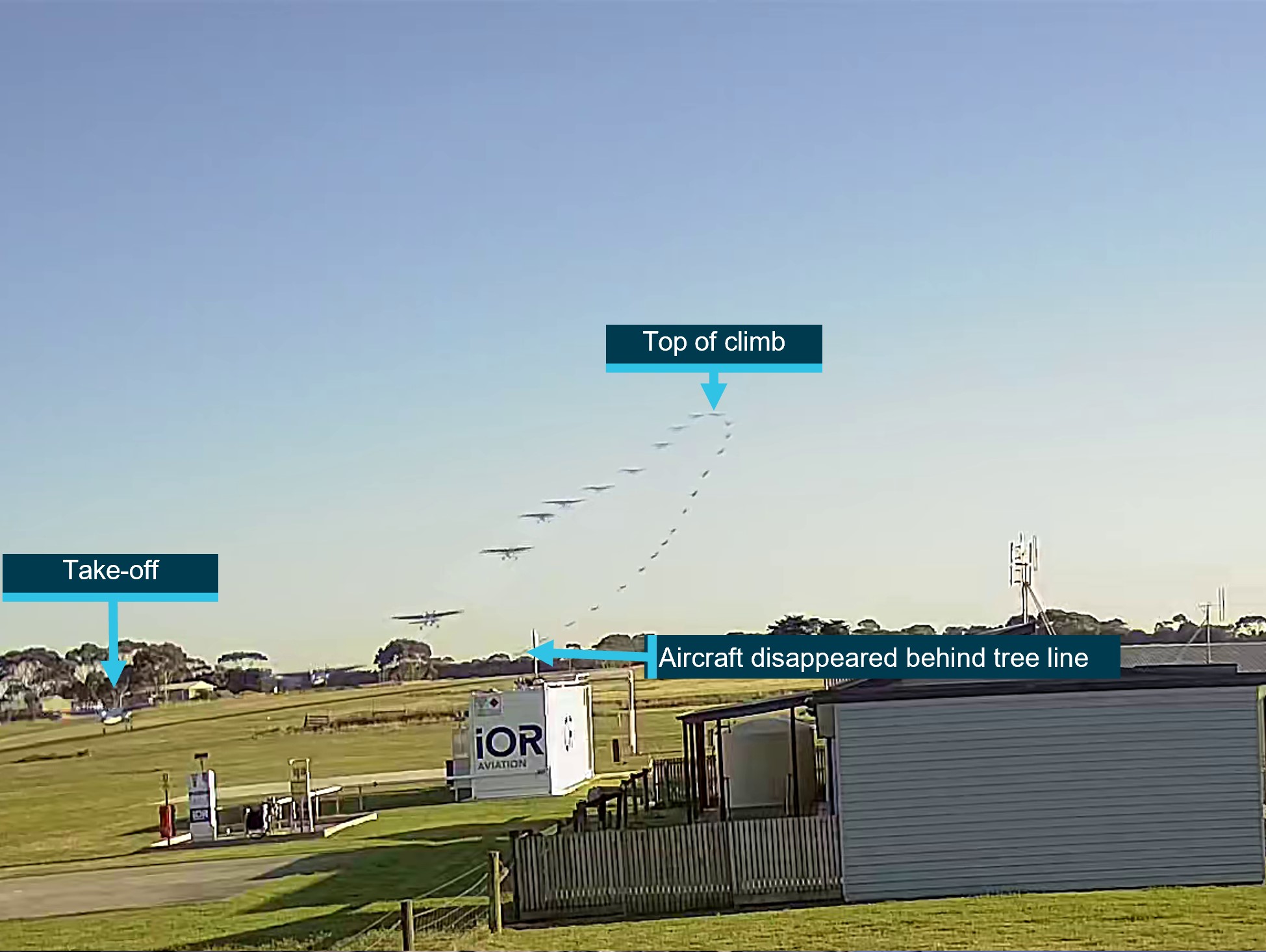
Figure 1: VH-UMV flight path captured by the airport camera

The ATSB combined multiple images together to show the flight path of the aircraft as captured by a local video camera. Source: Airport operator, annotated by the ATSB

The pilot reported that, as the aircraft descended, they observed the engine torque indication reducing through approximately 30% and attempted to switch off the TTL in accordance with the operator’s Engine Power Loss checklist. Due to the aircraft’s low height above the ground, and the pilot’s assessment that there was an engine issue, the pilot then selected a field in which to conduct a forced landing.

The pilot turned to the loadmaster[6] seated beside them and called out ‘gear-up’, to alert parachutists to be ready to exit the aircraft. In response, the loadmaster began directing parachutists to open the roller door, secure their harnesses, and brace for landing. The roller door was opened, but not secured in that position.

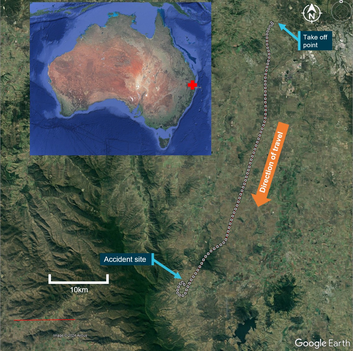
The pilot selected a forced landing location in a clearing beyond a river. However, less than 1 minute after becoming airborne and unable to maintain altitude, the aircraft impacted the water short of the clearing, resulting in water entering the cabin and forcing the unsecured roller door closed. The aircraft continued onto the riverbank where the main landing gear detached, then travelled along the ground for about 50 m before coming to rest (Figure 2).

The pilot sustained minor injuries, 6 parachutists sustained serious injuries, 8 sustained minor injuries and 2 were uninjured. The aircraft was substantially damaged. 

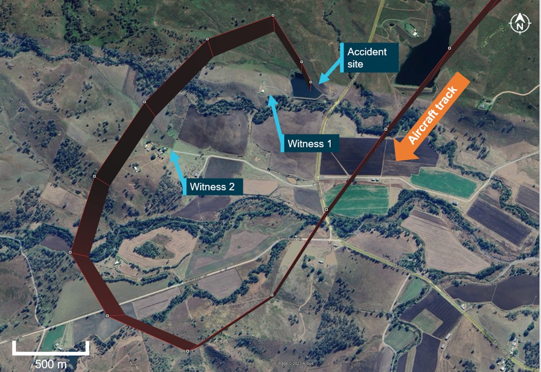
Figure 2: VH-UMV flight path
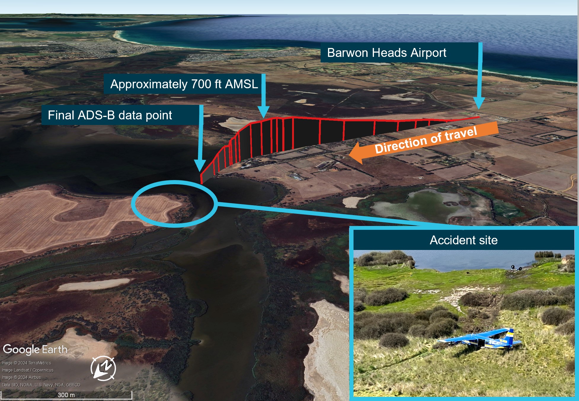
Figure 2: VH-UMV flight path

Source: ADS-B exchange flight data overlaid on Google Earth and image of accident site provided by operator, annotated by the ATSB

Context

Pilot information

The pilot held a commercial pilot licence (aeroplane) and a current class 2 aviation medical certificate. On 19 April 2023, the pilot completed their gas turbine engine design feature endorsement and single engine aircraft flight review in a Cessna 208 aircraft.

At the time of the accident, the pilot had accrued approximately 220 hours of total flight experience, which included 38 hours on the Cessna 208 aircraft type. Of those hours on type, 36 had been accrued in the previous 90 days.

The pilot reported that they were familiar with VH-UMV, having conducted multiple flights in it prior to the accident flight. The pilot was also aware of operator-specific engine operating limitations for VH-UMV, and reported having previously experienced an engine surge at 5,000 ft (see the section titled Engine surging).

Aircraft information

Certification details

The Cessna Aircraft Company 208 (C208) is an all-metal, high-wing aeroplane with tricycle landing gear and designed for general utility usage. The aircraft type certificate data sheet (TCDS) A37CE described the C208 as an ‘11-place closed land monoplane’, and under the heading ‘No. of seats’, provided a centre of gravity range for seating for one or 2 pilot seat locations and referenced the current Pilot’s Operating Handbook (POH) and United States (US) Federal Aviation Administration (FAA) Airplane Flight Manual (AFM) for passenger seat arrangements for seats 3 to 11.

The C208 POH Section 2 – Limitations – Maximum passenger seating limits stated that up to 11 seats, including the pilot’s seat/s, may be installed.

VH-UMV, serial number 20800077, was manufactured in 1986 and first registered in Australia in 2005. At that time, the aircraft was issued 2 certificates of airworthiness, one for normal category[7] operations and one for restricted category[8] operations for the purpose of carrying people for parachute jumping.

Operating in the restricted category required several conditions, including removal of the cabin seats, compliance with a specific engineering order and readily visible restricted category placards, none of which were in place on the accident flight. Additionally, under Civil Aviation Safety Regulations (CASR) current at the time of the accident (CASR 91.845, 91.025, 135.030), aircraft operating in the restricted category were not permitted to conduct air transport operations (carriage of passengers or cargo for hire or reward). 

In 2017, the aircraft’s Pratt & Whitney PT6A-114 gas turbine engine was replaced with a Honeywell International Incorporated TPE331-12JR-704TT gas turbine engine that drove a 4‑bladed, constant‑speed, full‑feathering,[9] reversible[10] Hartzell HC-E4N-5KL propeller with hydraulically‑operated variable‑pitch control. The engine modification was completed under the Texas Turbine Conversions supplemental type certificate (STC) SA10841SC, with an associated AFM Supplement. Under the heading ‘Maximum passenger seating limits’, the AFM supplement stated ‘No changes’ (from the C208 AFM). 

The aircraft was also modified in accordance with STC SA01180SE, which increased the original maximum take-off weight from 3,628 kg to 3,792 kg. Both STCs were approved by the US FAA and therefore accepted in Australia and taken as having been issued by CASA in accordance with CASR Part 21 regulation 21.114.

Three modifications made to VH-UMV and other aircraft in the operator’s fleet were completed under engineering orders in accordance with the CASR Part 21 regulation 21.437 Grant of modification/repair design approvals—grant by authorised person or approved design organisation:

  • ESE-C208-25-001—Rework of interior for parachute operations
  • ESE-C208-25-007—Installation of parachute bench seating
  • ESE-C208-95-003—Installation of Go-Pro cameras.
Torque and temperature limiter

VH‑UMV was fitted with a switch‑activated torque and temperature limiter (TTL) system designed to prevent these parameters exceeding specified limits. Where an exceedance of the allowable torque or exhaust gas temperature (EGT) was detected, the TTL computer restricted fuel flow to the engine. The maximum allowable fuel reduction of a normally-functioning bypass was about 68 L/hour (125 lbs/hour), resulting in a reduction of the torque output from 100% to about 62% (due to the approximate 25% reduction in fuel flow). 

Texas Turbine Conversions advised that, when functioning normally, the system would maintain the lower of the allowable torque or EGT limits and if the TTL bypassed the maximum allowable fuel, it would be felt immediately. In that case, the appropriate pilot response was to switch off the TTL.

The aircraft’s engine monitoring system included a single red line (SRL) controller, associated with the EGT limit. Like the TTL, the SRL was switch‑activated and deselection of the SRL also deactivated the TTL.

The allowable EGT limit was dependent on the phase of flight. Specifically, the operating margin from the EGT limit in the climb phase was reduced in the cruise phase. The phase was dependent on the position of the speed lever. Therefore, if the speed lever was moved aft during take-off or climb, the EGT limit also reduced and could result in activation of the TTL. The operator reported that the speed lever was fully forward throughout the short flight, and therefore the climb EGT limit applied. 

Operating limits

The AFM supplement for the Honeywell engine specified operating limits. With the SRL and TTL on, those limits included a maximum EGT of 650 °C, maximum 100% torque and maximum of about 101% RPM during take-off and climb. The supplement also provided an EGT table with limits for operating with the SRL off or inoperative, or ‘manual mode’. The limits were provided for operating at 100% RPM or 96% RPM based on the outside air temperature in 5 °C increments from −60 to +60 °C. 

The AFM defined take-off power as the lower of 100% torque or 650 ºC EGT (SRL ON), whichever is reached first at 100% engine RPM.

Engine surging

On 17 October 2023, the pilot submitted an internal safety report relating to an uncommanded engine surge, which they experienced at an altitude of approximately 5,000 ft. The pilot report stated:

Torque roll back for a split second, noticeable reduction in power and deceleration.

The pilot reported reducing the power then slowly increasing it while monitoring engine parameters in response to the event.

Although not recorded on the aircraft’s maintenance release (MR),[11] reportedly due to their transient nature, pilots submitted 7 other internal safety reports between July and October 2023 of engine surging in VH‑UMV, assessed as being due to the TTL. 

A review of maintenance recorded in VH-UMV’s engine logbook for the previous 12 months showed that the TTL controller was replaced ‘for fault isolation’ following the first reported surging occurrence on 3 April 2023. A further logbook entry on 18 September 2023 recorded that the EGT harness was replaced in response to reported engine surging at take-off power. 

The engine surging safety reports indicated troubleshooting test flights were also conducted. A series of test flights on 7 September 2023 was able to replicate the previously‑reported surging.  In addition, a test flight following the EGT harness replacement noted that the surging was still present. One of the experienced surges resulted in a torque value of 62% and fuel flow reduced by approximately 72 L/hour (128 lbs/hour). The MR current at the time of the accident identified that the aircraft operated over 90 flights prior to the next reported surge event on 17 October 2023. On that day, the aircraft operated 6 flights, and one surge occurrence was reported. According to the MR, 12 flights were conducted over the next 2 days (18–19 October), with no reports of engine surging submitted. However, the ATSB was also advised of an engine surge on 18 October, which was not recorded. 

The MR current at the time of the accident recorded 257 flights over 3 months, during which there were 6 reported surging events. That frequency illustrated the intermittent nature of the anomaly, which likely hindered troubleshooting.

As a result of the internal reports, on 21 July 2023, pilots were advised to operate VH-UMV under a set of unique operating conditions to avoid the TTL scheduling a significant bypass of fuel and subsequent notable drop in available power. These were limitations of 95% torque and 640 °C EGT. 

A review of the operator’s safety reports also identified that surging events were reported on 3 other company aircraft. For those aircraft, maintenance actions rectified the cause of each event and there were no subsequent surging events reported.

Minimum equipment list

Experience Co’s minimum equipment list (MEL) specified permissible unserviceable items with which the aircraft was permitted to operate temporarily under the stated procedures, conditions and limitations. The MEL included that both the SRL computer system and TTL ‘may be inoperative provided inoperative SRL system procedures and limits are observed’. In that case, it was also required that an MEL placard be fitted adjacent to the TTL or SRL switch for the inoperative system/s. There was no MEL placard for the TTL nor was it listed as inoperative at the time of the accident.  

Engine power loss checklist

The Texas Turbine Conversions AFM supplement provided checklists for engine failures, but not for partial engine power loss. The operator’s ‘Engine Power Loss’ checklist for the C208 with the Honeywell engine (Figure 3), required pilots to first control the aircraft by moving the elevator control forward to lower the aircraft’s nose if climbing. After completing initial checks, if the RPM was above 60% or the engine was surging, the pilot was to move the power lever to ½ inch (12.7 mm) forward of the flight idle position, in preparation for turning off the TTL, so as not to produce a transient exceedance of the EGT. 

Figure 3: Engine power loss checklist
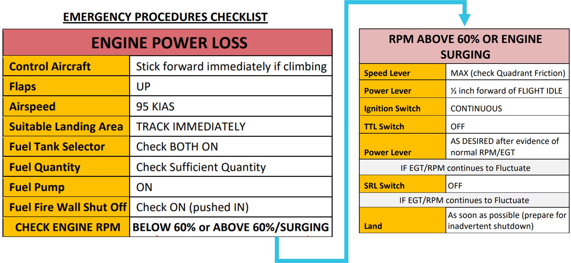
Figure 3: Engine power loss checklist

Source: Aircraft operator 

Weight and balance

Aircraft moment arms

To enable calculation of the aircraft’s weight and balance, the C208 POH included a 2-place seating option, which divided the cabin into 7 zones (zones 0–6) (Figure 4). The flight manual supplement for the Texas Turbine Conversions STC did not include changes to the zones or seating configuration, therefore the POH applied. 

Figure 4: Cessna 208 Pilot’s Operating Handbook seating configuration
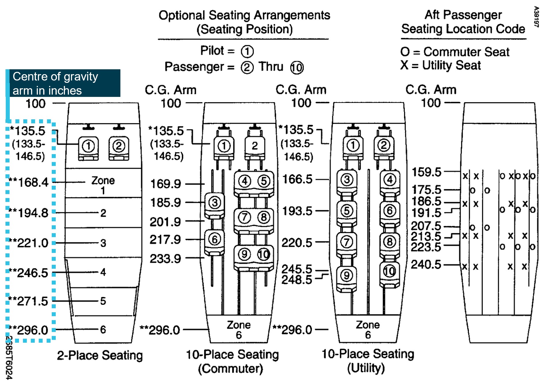
Figure 4: Cessna 208 Pilot’s Operating Handbook seating configuration

Source: Cessna 208 Pilot’s Operating Handbook, annotated by the ATSB

Accident flight weight and balance 

Prior to departure, a member of the parachuting operations team calculated the weight and balance for the proposed flight using the IBIS Technology flight planning module software (Table 1).[12] The moment arms from the POH were used for the calculations. Zone 6 was not used.

Table 1: Planned weight and balance for accident flight

ItemArm (mm)Weight (kg)Moment (kg-mm)
Aircraft basic empty weight4,1811,8897,897.909
Fuel4,680272.1521,273.672
Zone 0 [1]3,442272936.142
Zone 14,277218932.386
Zone 24,9483181,573.464
Zone 35,613173971.049
Zone 46,2614042,529.444
Zone 56,8961731,193.008
Total 3719.15217,307.075
Centre of gravity4,653  
  1. The operator’s weight and balance used the crew seat arm as the zone 0 arm.

The calculated weight and balance resulted in a take-off weight of approximately 3,719 kg and the aircraft’s centre of gravity located at 4,653 mm aft of the datum. To remain inside the operating limitations, the maximum allowable weight was 3,792 kg. Additionally, the aircraft needed to remain within the centre of gravity envelope, which had an aft limit of 4,680 mm and the forward limit varied with the operating weight. Each zone had a maximum allowable weight limit, and the maximum for zone 0 was 159 kg. However, the calculation software did not provide a warning to notify the user a zonal limit had been exceeded.

Information provided by the parachutists included the position they were seated at the time of the accident. Those positions did not match the original seating positions on the planned weight and balance sheet provided to the pilot prior to departure. The operator calculated a revised weight and balance based on the probable parachutist seating positions, which moved the aircraft’s centre of gravity 5 mm aft, although still within the allowable envelope (Table 2). It also showed that zone 0 was under the allowable weight limit.

Table 2: Revised weight and balance for accident flight

ItemArm (mm)Weight (kg)Moment (kg-mm)
Aircraft basic empty weight4,1811,8897,897.909
Fuel4,6802721,272.960
Crew seat3,44292316.664
Zone 03,47280277.760
Zone 14,277349.41,494.384
Zone 24,948271.41,342.887
Zone 35,613334.41,876.987
Zone 46,2611971,233.417
Zone 56,8962331,606.768
Total 3,718.217,319.746
Centre of gravity4,658  

Aircraft basic empty weight

A weigh of VH‑UMV on 17 October 2017 identified that the aircraft’s basic empty weight was 1,889 kg in the single pilot seat configuration (Figure 5).

Figure 5: VH-UMV configuration on date of reweigh
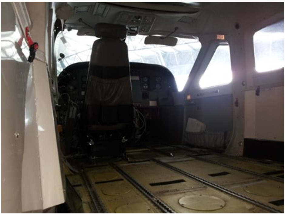
Figure 5: VH-UMV configuration on date of reweigh

The image meta-data showed the image was taken on 17 October 2017 – the reweigh date. Source: AeroWeigh.

The aircraft seating configuration at the time of the accident is shown in Figure 6.

Figure 6: VH-UMV cabin seating arrangement 
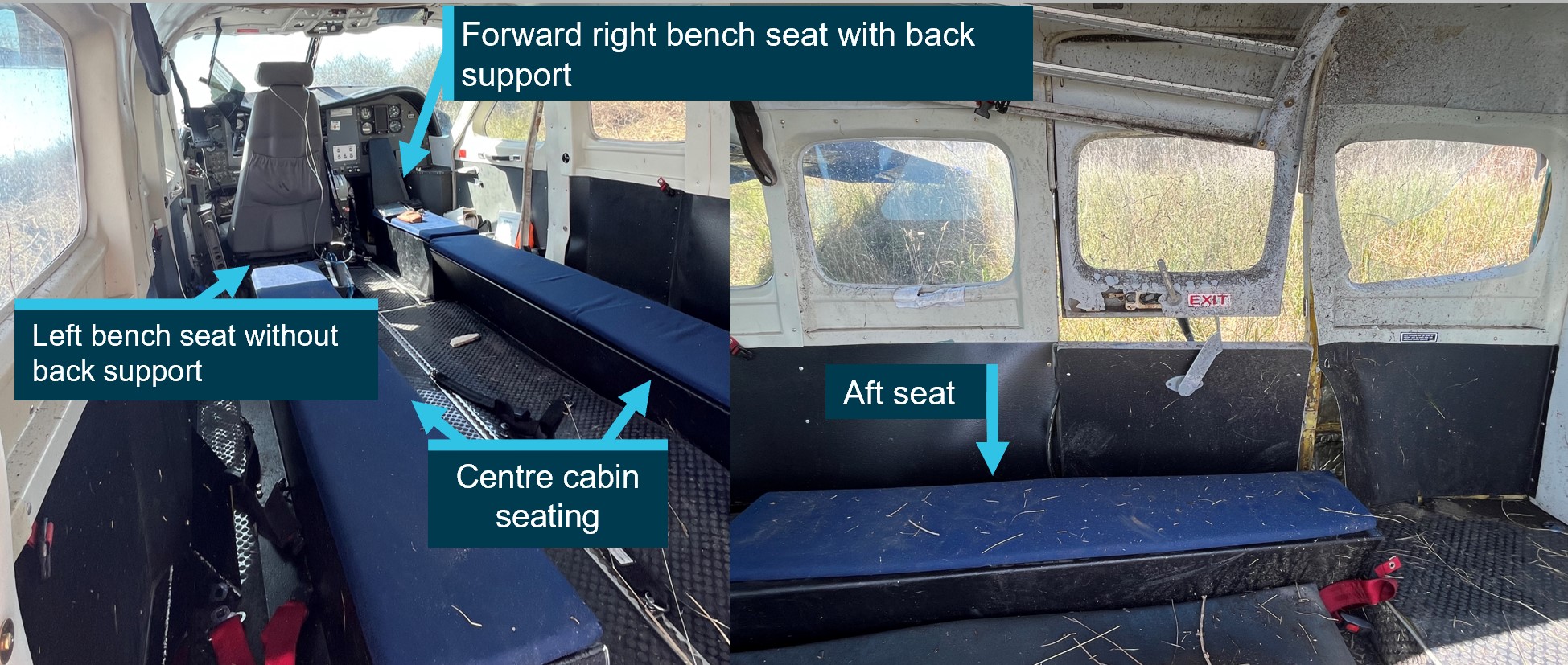
Figure 6: VH-UMV cabin seating arrangement

Source: Aircraft operator, annotated by the ATSB

The basic empty weight of the aircraft did not include the flooring, or the 36 kg bench seating installed under engineering order ESE-C208-25-007. The engineering order provided the moment arms and weights shown in Table 3.

Table 3: ESE-C208-25-007 Parachute bench seating options – bench seat weight and arm

ItemArm (mm)Weight (kg)
Forward seat & backrest right-hand side only – option 2, without oxygen bottle mount.3,5567.82
Centre cabin bench seats both left-hand and right-hand sides (2 x 10.92 kg)5,00321.84
Aft bench seat right hand side only6,5536.36
Total of unaccounted weight for bench seating 36.02

Using the operator’s revised weight and balance calculation that reflected the likely positions of the parachutists, and the additional weight of the bench seating, the ATSB determined the probable take-off weight was 3,754 kg and the centre of gravity was 8 mm aft of the originally calculated centre of gravity (4,661 mm).

The operator subsequently weighed the aircraft’s jump mat, single point restraints, rubber matting, and portable oxygen tank. The total of these items was 30.2 kg, increasing the probable take-off weight to 3,784 kg.

Weight and balance implications 

Regarding the importance of accurate weight and balance, the FAA Pilot’s handbook of aeronautical knowledge stated:

An overloaded aircraft may not be able to leave the ground, or if it does become airborne, it may exhibit unexpected and unusually poor flight characteristics.

Changes of fixed equipment have a major effect upon the weight of an aircraft. The installation of extra radios or instruments, as well as repairs or modifications, may also affect the weight of an aircraft.

Loading in a nose-heavy condition causes problems in controlling and raising the nose, especially during take-off and landing. Loading in a tail-heavy condition has a serious effect upon longitudinal stability and reduces the capability to recover from stalls and spins. Tail heavy loading also produces very light control forces, another undesirable characteristic. This makes it easy for the pilot to inadvertently overstress an aircraft.

Recorded data

The ATSB obtained OzRunways and third-party ADS-B recorded data for the accident flight. That data was compared with flight data for the flight conducted by the same pilot in the same aircraft on 17 October 2023, which was the day the pilot reported engine surging at about 5,000 ft. The comparison did not show significant performance difference from take-off to about 500 ft between the 2 flights.

Although the aircraft had an engineering order to fit GoPro cameras, they were not in place for the accident flight. The operator reported that these were only used during the creation of promotional footage and not during day-to-day operations. There was also no video footage from inside the aircraft, but the airport operator provided video footage from cameras located at the airport. One of those cameras recorded the accident flight footage (Figure 1) and provided audio for analysis.

The recorded audio included the aircraft noise and the nearby road and wind noise. The camera was stationary, therefore as the aircraft departed its sound signature reduced. Analysis of the audio conducted by Honeywell found that the engine RPM was approximately 99% throughout the take-off and initial climb. However, the engine noise was not discernible from the background sounds recorded at the time of the reported engine surge.

Site and aircraft examination

Site assessment

The ATSB did not attend the accident site, but the aircraft operator and Victoria Police attended shortly after the accident and provided the ATSB with photos of the aircraft and cockpit. A review of the images showed that the: 

  • flaps were fully retracted
  • power lever was in the max reverse position
  • speed lever was in the minimum position
  • condition lever was in shutoff/feather position.

Those positions were consistent with the pilot’s reported actions to secure the engine after the impact. Additionally, one image appeared to show the TTL switch ON and the SRL switch OFF, indicating that the pilot may have inadvertently selected the SRL OFF instead of the TTL.

Engine and accessories assessment

The aircraft’s engine was recovered by the operator and sent to the Honeywell Investigation Laboratory in the US. On behalf of the ATSB, the US National Transportation Safety Board (NTSB) arranged independent oversight of the engine examination that was conducted between 3–5 January 2024.

Honeywell and the NTSB subsequently oversighted inspection and testing of removed components at various technical facilities. The Honeywell investigation report, provided to the ATSB and aircraft operator, detailed the observations and findings from the engine and associated component examinations, as follows.

The SRL and TTL were tested on 27 February 2024. Although some test points were not within the specified test tolerances, both units were found to be functional. However, further examination of the fuel bypass valve conducted by Woodward Inc. on 5 November 2024, resulted in a maximum bypass flow of 110 L/hour (194.5 lbs/hour), which exceeded the maximum flow test range of 68–74 L/hour (120–130 lbs/hour). At take-off power, a normal fuel flow was approximately 312 L/hour (550 lbs/hour). Therefore, if a bypass of 110 L/hour occurred during the accident flight with take‑off power set, the fuel flow would have reduced by about 35%. 

Initial inspection of the fuel bypass valve’s outer casing revealed impact markings (Figure 7). When the protective cover plate was removed, the pole associated with the impact side was found in contact with the armature. When a 4.5 kg (10 lb) force was applied to each of the poles, there was no visible movement. The armature was cut away from the spade to determine if the armature screws were loose. The armature screws were found to be suitably tightened, and the armature was not bent.

The findings of the inspection showed the out‑of‑limit test results were due to impact damage resulting from the accident. As such, the higher fuel bypass identified in the test was not considered to be contributory.

Figure 7: Fuel bypass valve
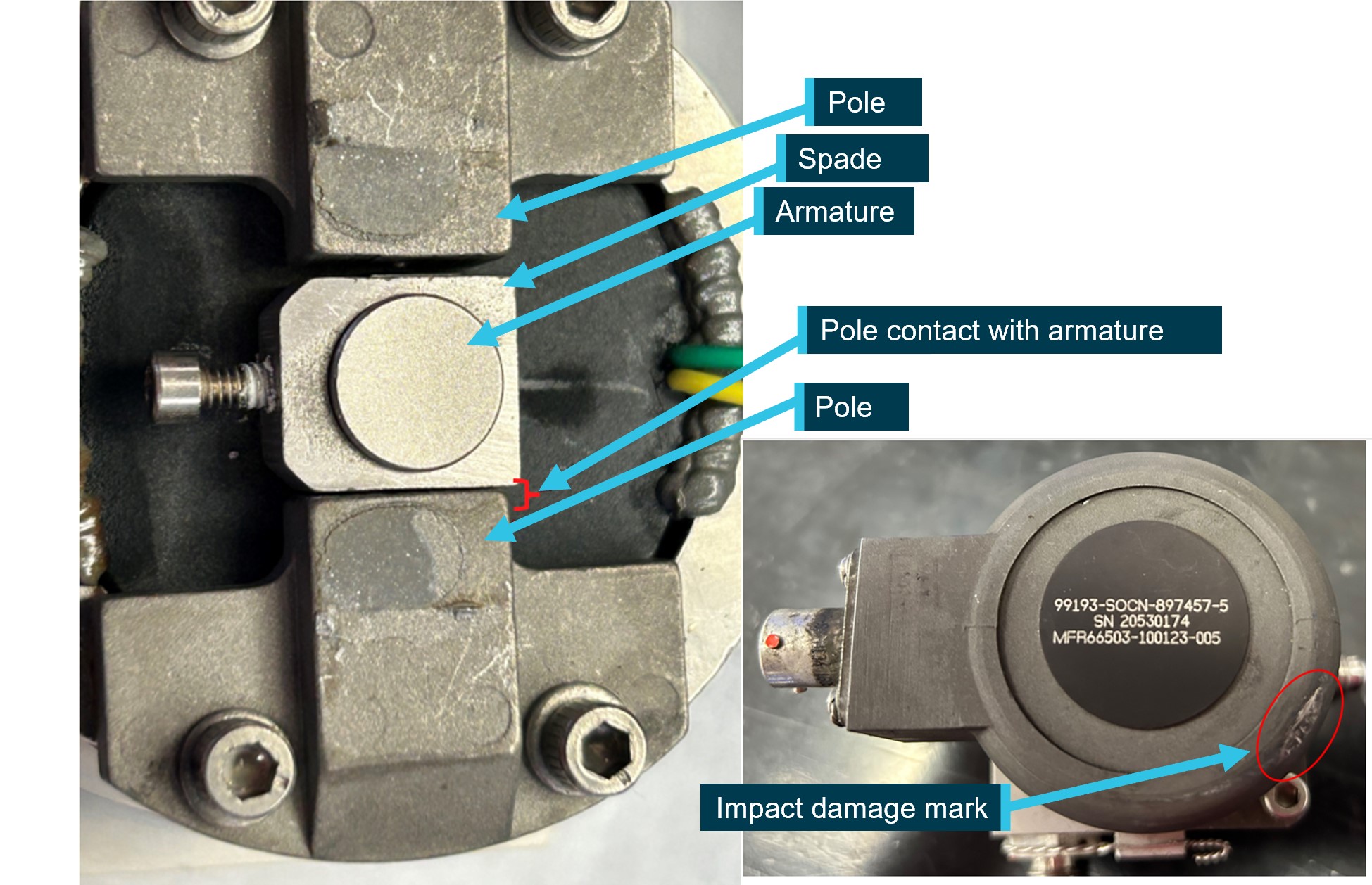
Figure 7: Fuel bypass valve

Source: Woodward Inc, annotated by the ATSB

The fuel control unit (FCU) was examined and tested between 26–27 March 2024. The FCU tested values were either within specified ranges or marginally outside of tolerance limits for new or overhauled components. The test results may have been affected by procedures for adjusting an in-service FCU defined in the engine maintenance manual. 

On 11 January 2024, a computed tomography scan of the propeller governor was conducted by Honeywell. Between 26–27 March 2024, the propeller governor was subject to functional testing by the manufacturer. While there were abnormalities identified with the magnetic pickup voltage and RPM maximum/minimum speeds, no contributing anomalies were noted. It was then disassembled, inspected and reassembled, followed by an additional functional test. The results from both functional tests were consistent with expected parameters of various operational modes.

The fuel pump was functionally tested on 2 May 2024, and found to be operating within specifications.

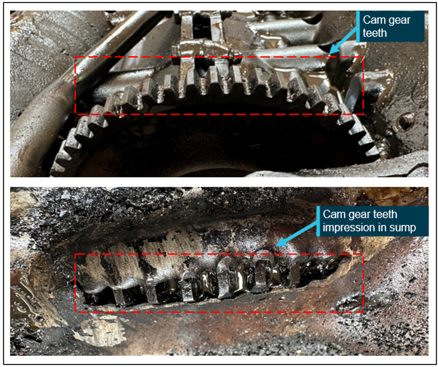
The Honeywell investigation found that the damage was indicative of an engine that was rotating and operating at the time of impact. It found no pre-existing condition that would have prevented normal operation. 

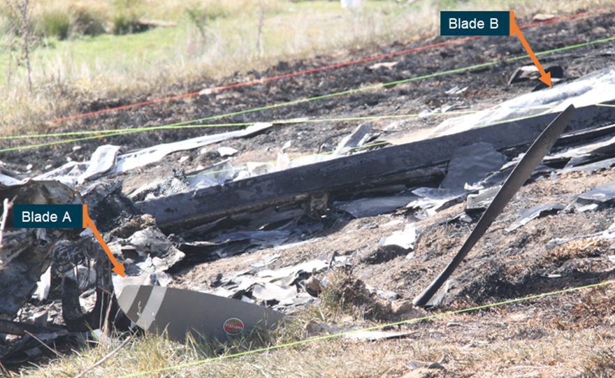
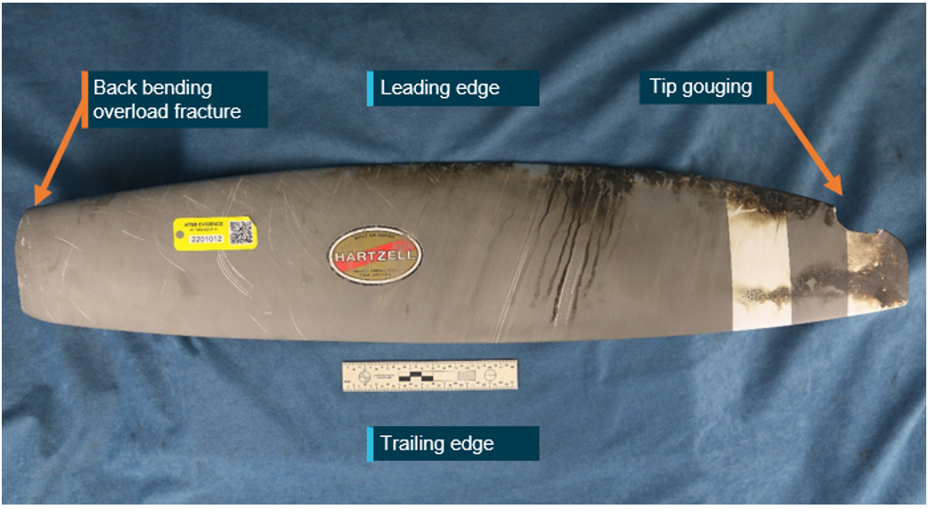
Photos of the propeller were provided to Hartzell for analysis. As the propeller was of composite material, on impact it fractured into parts rather than deforming the propeller shape. From the limited fragments that were retrieved, Hartzell concluded the blades were likely rotating under low power at the time of the accident.

The ATSB considered whether the pilot had moved the power lever to beta range, reversing the propeller, but Hartzell found it likely that the propeller was forced to a low pitch angle during the initial impact. 

Carriage of parachutists

Cabin configuration

The aircraft was configured for skydiving such that:

  • the cargo door was replaced with a vertical sliding door (made of nylon, polycarbonate and aluminium)
  • the passenger seats and lap belts were removed
  • bench seating and 17 single point restraints were installed.

The restraints attached to the parachute harness and parachutists could be seated either on the bench seating or floor, facing toward the aft of the aircraft. 

The associated flight manual supplements for the parachute configuration were: 

  • cargo doors removed kit
  • in-flight openable cargo door
  • in-flight opening of doors
  • oxygen system
  • skydiving jump light
  • external mounted GoPro cameras.
Aircraft modifications

Classification of design changes 

CASA stipulated regulations for modification of an aircraft from the original manufacturer specifications. CASA Advisory Circular (AC) 21-12 Classification of design changes provided different processes for modifying aircraft, depending on the type of change being made. These changes were classified as either major or minor.

A minor modification was anything that was not considered to be a major modification and could be completed by a CASA-authorised person under CASR Part 21.M. Any modification with a significant effect on airworthiness – structural, weight and balance, systems, operational or other characteristics, were classified as major. Additionally, any alteration to the type certificate datasheet was classified as a major change. 

A major modification was further classified into a substantial change or a significant change. A significant change required a supplemental type certificate application to be completed with CASA’s involvement. A substantial change required a new type certificate application, which also involved CASA. The AC provided the following example of a significant change to a small aircraft:

Changes in types and number of emergency exits or an increase in maximum certificated passenger capacity.

The notes associated with that example were: 

Emergency egress certification specifications exceed those previously substantiated. Invalidates assumptions of certification. 

CASA advised that the modifications would be considered a major change if the number of persons was increased above that permitted by the aircraft type certificate data sheet. This was consistent with the US FAA Advisory Circular 105-2E – Sport Parachuting, which included: 

The approved number of skydivers that each aircraft can carry for parachute operations will most commonly be found on FAA Form 337, Major Repair and Alteration (Airframe, Powerplant, Propeller, or Appliance), used for field approvals, or an aircraft Supplemental Type Certificate (STC).

In its submission to the draft report, CASA advised that it considered that the legal basis for conducting parachuting flights with a greater number of passengers than the TCDS specified may be met if the aircraft was modified appropriately by a suitably authorised person and there was an associated aircraft flight manual supplement.

In determining whether the parachuting configuration modification was major or minor, the CASA‑authorised design engineer assessed that it was minor as it had no significant effect on:

  • structure
  • cabin safety
  • flight
  • performance or function of:
    • systems
    • propellers
    • engines or powerplant installation
    • environment.

The engineer also assessed that the design did not:

  • alter airworthiness or operating limitations
  • require an adjustment of the type-certification basis

Technical assessment of modifications 

Aircraft modifications must meet the airworthiness requirements of the aircraft’s certification basis. According to the type certificate data sheet, VH-UMV was certified under FAR 23 amendments 23-1 through 23-28. Modifications were required to comply with standards from that or subsequent amendments. Technical assessments of the modifications detailed in the engineering orders nominated FAR 23 amendment 62 as the certification basis for the parachuting configuration modifications, including the roller door, bench seating and oxygen system. 

The technical assessments included a design compliance matrix, with the following key comments by the design engineer of relevance.

Weight and balance

The engineering order was to include that:

It is the operator’s responsibility to accurately update the aircraft’s load data sheet to reflect the quantity and positioning of oxygen bottles as this may vary dependant on the number of parachutists on a given high altitude drop.

Structure

Standard aircraft hardware is used to secure items of mass installed as part of the parachute fit out modifications. This modification does not alter or effect the strength of the aircraft structure to support all normal aircraft loads. All materials & fasteners used as part of this design package have been selected to have adequate structural properties for their intended use.

Flight loads

The document package includes instructions to ensure the Cessna standard Flight Manual Supplement for operations with the cargo door open/removed is in the Flight Manual.

Oxygen

The engineer assessed the oxygen requirements for conducting flights above 14,000 ft in an unpressurised aircraft, stating:

…The operators (max) occupant capacity for the 208 & 208B model aircraft is x16 & x20 occupants respectively. As such these aircraft must be fitted with a minimum of 2x oxygen dispensing face masks if more than x15 occupants are carried…

Emergency landing conditions

Engineers assessed that the oxygen cylinder restraints were adequate in all load cases. They also rated the seats to at least 170 lb (77 kg) as required by FAR 23.785.

Regarding the installation of the oxygen bottle the engineers provided the following: 

…the seat base and surrounding structure is adequate to support the small increase in weight due to the installation…there is no risk of the installation coming loose and inflicting serious injury on the cabin occupants. 

Control systems

The design package included instructions for the removal of the copilot control wheel and column in accordance with the aircraft maintenance manual, to configure the aircraft for parachuting operations. There was no change to the design or functionality of the pilot's primary flight controls.

Doors

The number and arrangement of doors was not altered by the modifications. Regarding ‘vibration and buffeting’, the parachute door had a proven service history, with no reported issues since the design was originally implemented in June 2012. Further, the roller-style parachute door was commonly installed on parachuting aircraft and Cessna had an approved roll-up door as part of the production standard design. 

Operation of the roller door was ‘simple and obvious’, easily operable from inside and outside the aircraft. The door was held in place by gravity and friction and could not be accidentally opened. Decals specific to the operation of the parachute roller door were installed. 

Seats and restraints

The single point restraints for the parachutists were previously approved for use by ‘Air Safety Solutions’. 

The aircraft certification did not require dynamic testing of the seats and, although the bench seating was not tested, the design engineer referenced FAA AC 105-2E Sport parachuting, which stated: 

1. Straddle benches can offer more occupant crash protection than floor seating since they can be designed to provide significant vertical energy absorption.

Emergency exits

For reference, FAR 23.807 required:

In addition to the passenger-entry door, for an airplane with a total passenger seating capacity of 16 through 19, three emergency exits, as defined in paragraph (b) of this section, are required with one on the same side as the passenger entry door and two on the side opposite the door.

(b) Emergency exits must be movable windows, panels, canopies, or external doors, openable from both inside and outside the airplane, that provide a clear and unobstructed opening large enough to admit a 19-by-26-inch ellipse. Auxiliary locking devices used to secure the airplane must be designed to be overridden by the normal internal opening means. The inside handles of emergency exits that open onward must be adequately protected against inadvertent operation. In addition each emergency exit must:

• be readily accessible, requiring no exceptional agility to be used in emergencies;

• have a method of opening that is simple and obvious;

• be arranged and marked for easy location and operation, even in darkness;

• have reasonable provision against jamming by fuselage deformation; …

(c) The proper functioning of each emergency exit must be shown by tests

The design engineer commented that there was no change to the number of emergency exits and that the ‘steps, handles, bench seats etc. installed for this modification met the requirements for egress in an emergency as specified by this regulation’. Additionally, as there was no change to the door functionality or positioning, no additional emergency testing was required.

The unmodified rear right passenger door met the requirements of the regulation in that a 19" x 26" (48 x 66 cm) ellipse may be passed through the door un-obstructed. However, the rear right bench seat extended across the door at a height of 10” (25.4 cm). The design engineer commented that access to the door handles/operation and decals was not obstructed, and no exceptional agility was required to exit through that door in an emergency.

The roller door was also required to meet the emergency exit criteria, including ‘reasonable provisions against jamming by fuselage deformation’, and that ‘proper functioning of each emergency exit must be shown by tests’. However, this was not documented. 

The parachuting configuration detailed in the engineering orders enabled seating and single-point restraints for 17 parachutists, in addition to the fitted pilot seat and 5-point restraint. The design engineer had not intended to explicitly increase the seating capacity above the 11 specified in the TCDS, as the number of parachutists that could be carried was an operational consideration. The design engineer provided comment on a technical assessment provided to CASA in 2017 regarding maximum passenger seating configuration, that the aircraft operator’s understanding was: 

it is the pilots [sic] responsibility to ensure the aircraft is loaded within the weight and balance and centre of gravity limitations of the aircraft at all times. From these calculations the maximum safe number of parachutists to carry on the Cessna 208 Caravan is 17...

Regulatory requirements 

Part 105 of the CASR came into effect in December 2021 and set out the operational requirements for aircraft used to facilitate parachute descents. Civil Aviation Order (CAO) 20.16.3 paragraph 15 Carriage of parachutists was in force at the time of the accident, and the following regulations were relevant to the aircraft parachuting configuration:

  • CASR 91.200 Persons not to be carried in certain parts of aircraft permitted a person to be carried in ‘a part of the aircraft that is not designed to carry crew members or passengers’, if the aircraft was being operated for a parachute descent and met the Part 105 MOS.
  • CAO 20.16.3 required parachutists to wear a seatbelt, shoulder harness or approved single point restraint (except when about to jump). Similarly, CASR Part 105 section 105.105 required parachutists who were not flight crew to be provided with a seatbelt, shoulder harness or approved single-point or dual-point restraint.

The Part 105 Manual of Standards (MOS) came into effect on 2 December 2023, 44 days after the accident, and specified requirements in greater technical detail. CASA advised that the Part 91 Manual of Standards will be amended to remove ambiguity about approved passenger restraints being permitted in lieu of seatbelts.

Maximum passenger seating configuration

In drafting CASR Part 105, the number of parachutists that could be carried was a significant point of discussion between CASA and the parachuting industry. 

In 2006, CASA proposed Civil Aviation Safety Regulation 105.140 paragraph 3.5.20 which stated:

Proposed CASR Part 105 seeks to provide clarity to the parachuting industry that operating a parachuting aircraft with more parachutists than the normal published aircraft seating capacity in passenger-carrying operations is acceptable, provided weight and balance and other manufacturer’s limitations for the aircraft are observed.

A subsequent notice of proposed rulemaking indicated that the following may be included in the proposed CASR Part 105.140 – Number of parachutists in aircraft: 

(1) A parachuting aircraft may carry more occupants than the maximum number that is specified in the aircraft’s flight manual only if the aircraft is loaded in accordance with the following requirements and limitations set out in the flight manual or the certification data for the aircraft: 

(a) the weight and balance requirements; and…

When the above proposed rule was not incorporated into draft CASR Part 105 or MOS, as detailed in meeting minutes of the technical working group that reviewed the 30 August 2022 draft Part 105 MOS, they proposed to meet with CASA’s Airworthiness and Engineering Branch to discuss:

possible options for parachuting aircraft to operate with seats removed, to carry more passengers than currently permitted by the aircraft’s type certificate or flight manual and regulatory support mechanisms for modifications (doors, handles etc.) that support safe parachuting operations. 

The ATSB was unable to determine whether this discussion took place, however no related changes were incorporated into the regulations or MOS, noting that the MOS had not come into effect at the time of the accident. 

In response to the ATSB’s request for clarification of CASA’s expectation for the number of parachutists that could be carried, CASA advised that:

  • The legal basis for conducting parachuting flights with a greater number of passengers than the TCDS is met where the aircraft has been modified appropriately by a suitably authorised person and the aircraft’s flight manual has been modified accordingly.
  • CASA has been aware for multiple decades that parachuting aircraft were carrying a maximum number of passengers greater than the TCDS maximum number of dedicated passengers.
  • CASA understood that the increase in passenger capacity for parachuting aircraft was achieved by operators through legitimate aircraft modification processes that removed the normal passenger seats and modified the aircraft for parachute‑specific operations.
  • CASA did not identify any immediate safety of flight issues.

In its submission to the draft report, CASA advised that it was ‘considering the issue of a legislative instrument to remove any doubt that an approved aircraft modification which replaces normal seating with appropriate alternative seating and restraint arrangements is explicitly permitted’.

Supplemental type certificate application

In April 2017, the design engineer applied to CASA on behalf of the aircraft operator for a supplemental type certificate based on the engineering order for the addition of bench seating. The STC application submitted to CASA included details and images of aircraft that already had modifications completed under an engineering order and did not include an increase in the seating capacity.

After several communications and iterations of the documents provided, in August 2017, CASA highlighted 2 areas directly related to safety of parachutists: the rear exit crashworthiness and the increase of maximum passenger capacity to 17.

In July 2020, the STC application was withdrawn by the applicant.

Other parachuting configuration supplemental type certificates

Cessna 182 models E to R­

In 1996, CASA issued STC-214 to the APF. The STC background explained the application was the result of a CASA ramp check, which identified that there were 6 persons on board without single point restraints while conducting parachute operations, where the TCDS stated it was a 4‑seat aircraft.

The STC assessed the floor loading capacity of the aircraft to carry 6 persons (including the pilot) for the purpose of parachute operations. It concluded:

The floor was analysed and substantiated for parachutist loads. The hard points for the approved single point restraints were determined, analysed and substantiated for parachute loads... The aircraft loading is such that no special loading system needs to be devised as the aircraft will always be within the approved centre of gravity range.

The original C182 TCDS 3A13 showed ‘No. of seats 4’.

The amended TCDS for the STC showed ‘No. of seats 1, Parachutist 5’.

Cessna 208, 208B

In 2018, the US FAA issued supplemental type certificate SA04352CH, which incorporated many similar modifications made to model 208 and 208B aircraft certified under A37CE. The modifications included the installation of:

  • wind deflector
  • benches
  • external assist handle
  • internal assist handle
  • jump exit control light
  • external step
  • wind block (sliding parachute door).

The STC limitations and conditions included:

(3) This modification does not install Title 14 [US Code of Federal Regulations] CFR part 23 compliant seating and is therefore zero occupancy.

(4) The left and right hand benches are compliant as monuments and are not certified to carry any items of mass. Testing performed during certification would be sufficient for gust loading or seven evenly distributed masses of 215 pounds (97.5 kg) each…

Australian Parachute Federation

The APF is the peak body for the administration and representation of Australian Sport Parachuting. With the approval of the Civil Aviation Safety Authority, the APF:

  • applies the standards of operation
  • conducts competitions
  • issues parachuting licences, certifications and instructor ratings
  • conducts exams
  • distributes publications to keep its members informed of events and safety standards.

The APF organisation had over 55 group members also known as member organisations, 3,000 licenced members, and engaged with the operators of nearly 100 aircraft conducting parachute operations. As detailed above, the APF held an STC for parachuting operations in Cessna 182 models E through R for parachuting 6‑person operations. The associated supplemental type certificate data sheet amended the aircraft configuration to 1 seat and 5 parachutists from the 4‑seat configuration stated on the type certificate data sheet.

Aircraft operators that conducted parachuting operations as a member of the APF did so in accordance with the APF regulations. This included adhering to the APF Jump Pilot Manual. The Jump Pilot Manual Version 01-2023, in force at the time of the accident, stated:

5.3.3 Loading – Balance/C of G

A parachuting aircraft may carry more occupants than the maximum number that is specified in the aircraft’s flight manual only if the aircraft is loaded in accordance with the following requirements and limitations set out in the flight manual or the certification data for the aircraft:

  (a) the weight and balance requirements; and

  (b) any other limitations related to the provision of: 

       (i) adequate structural support for restraint of occupants; or

       (ii) supplemental oxygen for the flight.

For paragraph 5.3.3 (b), the limitations do not include those that are solely related to the number of seats or seating positions that are, or are normally, fitted in the aircraft.

If an aircraft does not have a flight manual, then any information supplied by the manufacturer that relates to the matters mentioned above or is included in the aircraft’s airworthiness certificate, is taken to be the flight manual.

Balance must be a consideration for all aircraft involved in parachuting operations and can be especially critical during climb-out and exit, when changes occur. Know the operational limitations of your aircraft!

Under the Loadmaster’s supervision, the parachutists will normally load the aircraft in the reverse order of the exit.

The Jump Pilot Manual was accepted by CASA and CASA personnel reported having reviewed the manual. Regarding the wording that a parachuting aircraft could carry more occupants than the maximum specified in the AFM, CASA reported that they understood that only applied to Cessna 182 models E through R, for which the APF held a supplemental type certificate that permitted the carriage of 6 persons. CASA personnel also reported that the manual wording was ‘never intended to serve as a quasi-engineering approval’.

At the time of writing, CASA and the APF were engaged in ongoing discussions, including the carriage of occupants in excess of the number detailed in the TCDS without the necessary modification approvals.

Survivability

Passenger briefing requirements 

The CASA Multi-Part Advisory Circular – Passenger safety information, stated:

2.1.1 In addition to certification standards for the crashworthiness of the aircraft and cabin crew evacuation procedures, well-informed and knowledgeable passengers contribute to survivability in an aircraft accident or incident. There are multiple factors that affect survivability. Physical factors include adopting the correct brace position for impact, the correct use of seatbelts, as well as the location and operation of all emergency exits.

2.1.2 Accident investigations have shown that survival rates are improved when passengers are provided with accurate and effective information about the correct use of equipment such as seatbelts, and the actions they should take in a life-threatening situation such as how to adopt the brace position.

A pilot in command was in contravention of regulation 91.565 if an aircraft commenced a flight and the passengers had not been given a safety briefing and instructions as prescribed by the Part 91 MOS, unless:

(a)  the passenger has been previously carried on the aircraft; and

(b)  the passenger has previously been given a safety briefing and instructions in accordance with this regulation; and

(c)  in the circumstances it is not reasonably necessary to give the same safety briefing and instructions.

The CASR Part 91 MOS provided a list of items that must be covered in a passenger safety briefing and instructions before an aircraft takes off for a flight. Relevant to this occurrence, the list included:

(c) when seatbelts must be worn during the flight, and how to use them;

(f) how and when to adopt the brace position;

(g) where the emergency exits are, and how to use them;

(s) for a flight of a jump aircraft — the physical location(s) within, or on, the aircraft that the passenger must occupy during the flight in order to ensure the aircraft is operated within the aircraft’s weight and balance limits during the flight.

Operator’s safety briefing

The aircraft operator had 2 videos, one of which was shown to parachutists depending on whether they were conducting a tandem jump or a sport jump. The sport jump video was specific to the Barwon Heads operation and included:

  • aircraft climb performance
  • 17 single point restraints, which were to be worn up to 2,000 ft
  • sport jumpers were to listen to the pilot in command in the event of an emergency
  • location of the door securing clip (but not instructions for use). 

The video shown to tandem jump parachutists provided specific aircraft safety information including:

  • how to approach the aircraft
  • the use of single point restraints
  • the location of fire extinguishers
  • how to brace
  • how to egress
  • the requirement not to smoke
  • the use of life jackets where required.

For the accident flight, the pilot reported that they did not provide a safety briefing, and multiple parachutists reported not having received a safety briefing prior to flight. There was no procedure in the operations manual that waived the pilot’s responsibility to provide parachutists with a safety briefing. The pilot reported that they understood that the drop zone safety officer ensured everyone was briefed on emergency situations before jumping and a video briefing was provided to tandem parachutists.         

The operations manual provided the following guidance for providing a safety briefing during an emergency landing with parachutists on board:

It will be the Load Masters responsibility to assist the pilot in ensuring;

1. Parachutists are briefed on and instructed to assume the BRACE position prior to touchdown.

2. Emergency Exits are opened and secured (where possible) prior to touch down.

3. Single point restraints are utilised by all occupants.

The aircraft also had a sign on the rear wall of the internal cabin, detailing the in-flight emergency plan (Figure 8). The sign stated that single point restraints were required as directed by the pilot and at all times below 1,500 ft, differing from the 2,000 ft stipulated in the sport jump video. 

The APF Jump Pilot Manual required that restraints were utilised by all occupants below 1,000 ft, or as directed by the pilot.

Figure 8: In-flight emergency plan
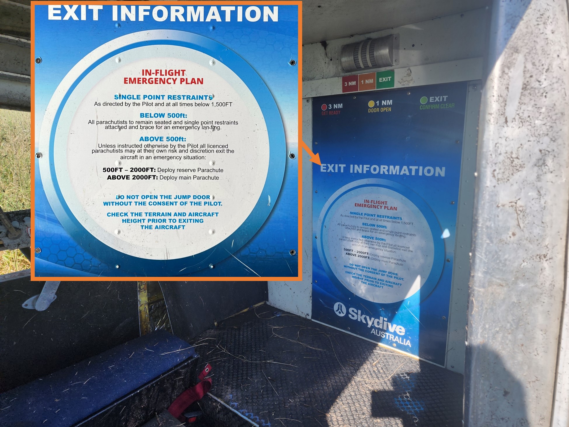
Figure 8: In-flight emergency plan

Source: Victoria Police and the aircraft operator

Parachutist preparedness

After the accident, in response to an ATSB survey, parachutists reported a lack of awareness of how to brace and the location of emergency exits that were available if the main roller door became damaged and unavailable for use in an evacuation. On this occasion the clip that secured the roller door in the open position was not used, which resulted in it closing on impact. Fortunately, the parachutists were still able to successfully evacuate the aircraft via that door. As detailed further below, several of the parachutists also reported that their restraints were not taut prior to the ground collision.

Some parachutists recalled receiving aircraft-specific emergency information during their initial parachuting training. However, in some cases, several years had passed without receiving a refresher. Furthermore, some had conducted their initial training on different aircraft types.

Injuries and seating positions

The pilot wore a 5-point restraint, and the 16 parachutists each had a single-point restraint attached to their parachute. The probable seating arrangement at the time of the accident was determined based on the recollections of parachutists who responded to ATSB’s request for information (Figure 9). There were 4 parachutists seated on the floor, 4 on the left bench seat and 8 on the right bench seat. The parachutists were facing aft and those on the bench seats were seated between each other’s legs. 

Injury information was obtained for the pilot and 14 of the 16 parachutists, with the other 2 assumed to have no injuries (Table 4). The injury mechanisms included deceleration, flail and impact with the aircraft or other occupants.

Figure 9: Seating positions
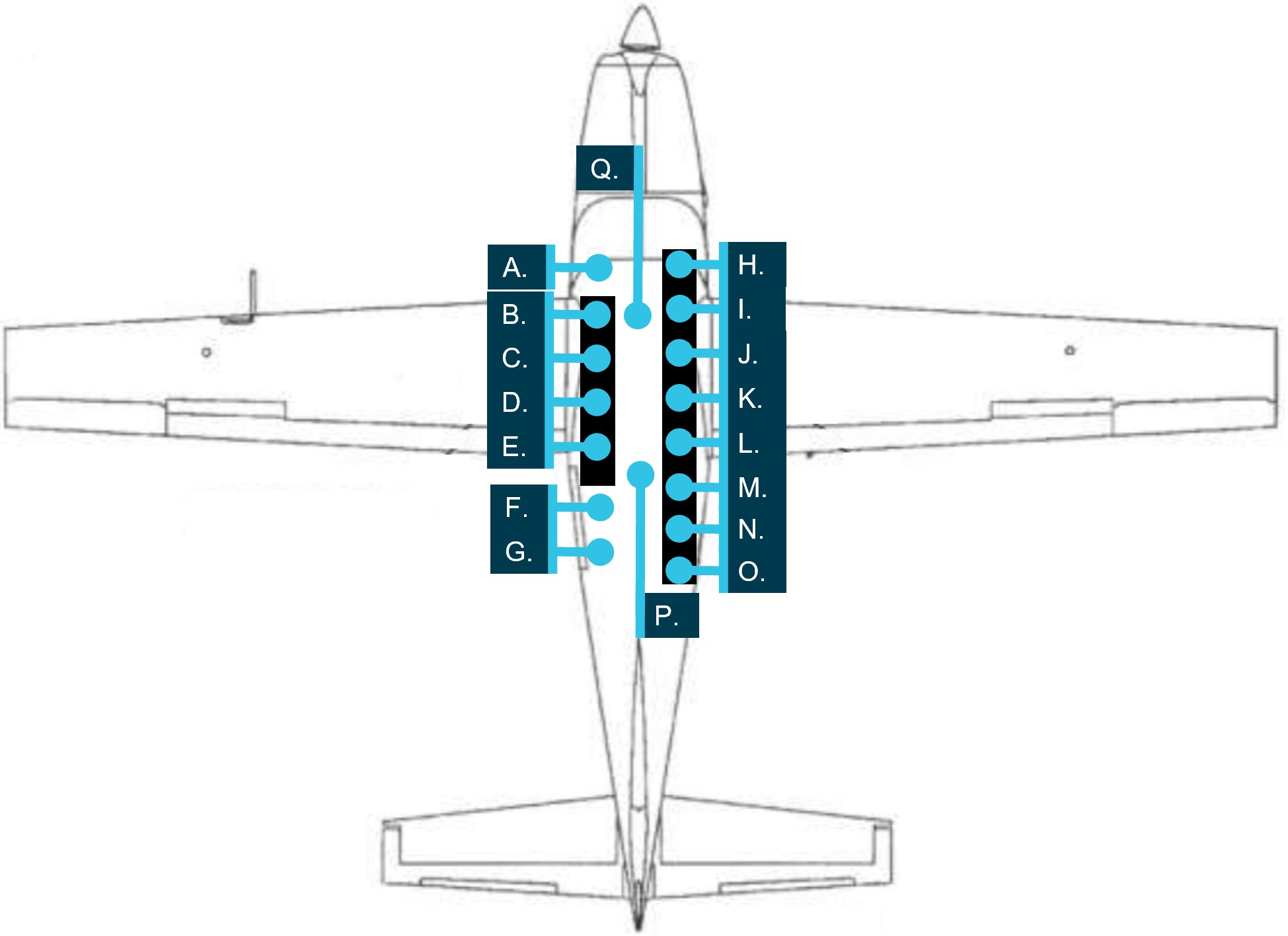
Figure 9: Seating positions

The seating positions in the image are referenced in Table 4: Injuries sustained. Source: Texas Turbines Cessna 208 pilot operating handbook, annotated by the ATSB

Table 4: Injuries sustained

Image referenceInjuries sustainedATSB injury classificationSurvivability Comments
A. (Pilot)Cut on forehead, bruising, whiplash, bruised sternum, and difficulty talking/breathingMinor5-point safety harness; likely impact with control column/dash
B.Pulmonary contusion, fifth and sixth rib fractures, psychological trauma, and lower back painSeriousSlipped off the end of the bench seat and ended up squashed against the ladder or back of the pilot seat due to a loose restraint 
C.No reported injuriesNo injuries 
D.Tears to both rotator cuffs, tear to sternocleidomastoid muscle, and nerve damage to left arm and shoulderSerious 
E.Broken ribs and internal bleeding to the chest.SeriousLoose restraint
F.Whiplash, fractured L4 transverse process, and nerve pain in right shoulder and legSeriousLoose restraint, seated on floor; adjacent end of bench seat
G.Whiplash, bruising, and headachesMinorSeated on floor
H. (Loadmaster)Cut injury to right leg requiring stitches, and sore backMinor 
I.Strained back, cuts, and bruisingMinor 
J.Whiplash, cuts, and bruisingMinorLoose restraint
K.Whiplash, cuts, and bruisingMinorLoose restraint
L.Cuts to head, face, internal chest cuts, and bruising MinorTight restraint
M.Broken tailbone, bruisingSeriousTight restraint
N.Concussion, and bruisingMinor 
O.Swollen knee, bruised kidney, bruised vertebrae, and strained neck ligamentsMinorLoose restraint
P.Internal abdomen bleeding, Internal hematoma inner right leg, cuts, bruising, whiplash, and back pain.SeriousLoose restraint; inappropriate structures around/in front 
Q.No reported injuriesNo injuries 

The single point restraints could not be adjusted, but an occupant could potentially position themselves such that the restraint was taut. Nine parachutists provided information about the tightness of their restraint; 7 reported their restraints were loose and 2 reported tight restraints. Of those with loose restraints, 3 sustained minor injuries and 4 sustained serious injuries. Of the 2 parachutists who reported having tight restraints, one sustained minor injuries and the other sustained serious injuries.

Of the 4 parachutists seated on the floor, 2 sustained serious injuries, one sustained minor injuries, and another was reported to have been uninjured. The other serious injuries were sustained by 2 parachutists on the left bench seat and one on the right bench seat. 

The parachutist who sustained the most injuries of the highest severity was at the front of the left bench seat. As that bench seat did not have a seatback, the parachutist came off the forward end of the bench between the bench and pilot seat and contacted the back of the pilot’s seat and/or ladder adjacent to the seat. The injuries were likely also increased by the mass of the 3 other parachutists on that bench moving forward during the impact sequence. 

The ATSB compared the injuries sustained by the pilot and parachutists of VH-UMV with those involved in 2 survivable accidents involving C208 aircraft, assessed as likely to have been subjected to similar impact forces (AO-2016-007 and AO-2024-001). In the 2 comparative accidents, some of the occupants sustained minor injuries while others were uninjured. The pilot and front seat passengers had 5-point restraints, and in the 2016 accident the other passengers wore lap belts. In the more recent accident, the other passengers wore 3-point restraints.   

ATSB investigation AO-2014-053 found that single point restraints were less effective than dual restraints in mitigating injury for parachutists. This was consistent with the US FAA’s technical report – Evaluation of Improved Restraint Systems for Sport Parachutists, which found that dual straps attached to the parachute harness provided better restraint and produced less flailing and bending of the body than single point restraints (FAA 1988). The following loading of aft‑facing passengers was found to increase restraint effectiveness:

• the person most forward in the cabin should be leaning against a bulkhead or other substantial support to limit flailing and head impact.

• each parachutist’s restraint should be anchored to the floor aft of his/her pelvis (relative the aircraft’s orientation) at a point on the floor near the middle of the thigh. The restraint should be taut to reduce forward motion, and the loads transmitted to the person behind.

• the proper brace for impact position would be to lean toward the front of the aircraft onto the person or bulkhead behind them.

The US FAA AC 105-2E Sport parachuting also stated that single point restraints were ‘not very effective’, and that dual point restraints offered ‘superior restraint’. 

The ATSB assessed that the increase in number and severity of injuries of the parachutists compared to passengers seated and restrained in seats, was probably a result of single-point restraints being less effective and less cushioning due to being seated on the floor or bench.  

Related occurrences

National Transportation Safety Board Special investigation report

The US National Transportation Safety Board (NTSB), Special investigation report on the safety of parachute jump operations (2008), found that between 1980 and 2008 in the US, 32 accidents involving parachute aircraft resulted in fatal injuries of 172 people, most of whom were parachutists. Acknowledging risks associated with parachuting, the report stated:

Although parachutists, in general, may accept risks associated with their sport, these risks should not include exposure to the types of highly preventable hazards that were identified in these accidents and that the parachutists can do little or nothing to control. Passengers on parachute operations aircraft should be able to expect a reasonable level of safety that includes, at a minimum, an airworthy airplane, an adequately trained pilot, and adequate Federal oversight and surveillance to ensure the safety of the operation.

Of the 32 accidents, 8 involved exceedances of the aircraft’s weight and balance, and 21 resulted from inadequate airspeed or stall situations, and in 6 accidents, both were factors. There was one accident involving a Cessna 208, which resulted in 17 fatalities.

The report also acknowledged that parachuting is typically a revenue operation where a participant pays for a jump and receives the flight as part of that service, it stated:

Most parachute operations flights are operated under the provisions of 14 Code of Federal Regulations (CFR) Part 91 and are typically revenue operations; parachute jump operators provide the flights as part of their services to parachutists who pay to go skydiving, or parachutists pay dues for membership in parachuting clubs. The risks of parachuting are generally perceived to involve the acts of jumping from the aircraft, deploying the parachute, and landing; parachutists are aware of and manage these risks. However, a review of accident reports reveals that traveling on parachute operations flights can also present risks.

The report highlighted the potential for paying participants to be unaware of the risks they were accepting when they boarded a parachute aircraft.

The report identified the following recurring safety issues:

• inadequate aircraft inspection and maintenance;

• pilot performance deficiencies in basic airmanship tasks, such as preflight inspections, weight and balance calculations, and emergency and recovery procedures; and 

• inadequate FAA oversight and direct surveillance of parachute operations.

Recent accidents

The following 3 more recent accidents involved aircraft conducting parachuting operations and resulted in injuries to the occupants.

  • Loss of engine power after take-off involving Cessna 208B, PH-FST, West of International Airport Teuge, Netherlands, on 25 June 2021 (2021062)

On 25 June 2021 at 0932 local time, a Cessna 208B with a pilot and 17 parachutists on board departed from International Airport Teuge. During the initial climb, the aircraft suddenly lost engine power after which the pilot made an emergency landing in a field close to a motorway. The aircraft was substantially damaged, and one parachutist sustained minor injuries.

  • Accident involving GA8-TC-320 Airvan, SE-MES, Storsandskär, Västerbotten, Sweden, on 14 July 2019 (RL 2020:08e).

The purpose of the flight was to drop 8 parachutists from an altitude of 13,000 ft. On the drop run, the pilot lost control of the aircraft. The parachutists were unable to evacuate the aircraft resulting in fatalities of the 9 persons on board.

The investigation found that control of the aeroplane was probably lost due to low airspeed. Other contributing factors were that the aeroplane was unstable as a result of a tail-heavy loading, weather conditions, and a high workload in relation to the pilot’s knowledge and experience.

  • Loss of control involving Cessna U206G, VH-FRT, Caboolture Airfield, Queensland, on 22 March 2014 (AO-2014-053)

On 22 March 2014, a Cessna U206G aircraft was being used for tandem parachuting operations at Caboolture Airfield, Queensland. At about 1124 local time, the aircraft took off from runway 06 with the pilot, 2 parachuting instructors and 2 tandem parachutists on board. Shortly after take-off, witnesses at the airfield observed the aircraft climb to about 200 ft above ground level before it commenced a roll to the left. The left roll steepened, and the aircraft then adopted a nose‑down attitude until impacting the ground in an almost vertical, left-wing low attitude. All the occupants on board were fatally injured. A post-impact, fuel-fed fire destroyed the aircraft.

The ATSB identified that the aircraft aerodynamically stalled at a height from which it was too low to recover control prior to collision with terrain. The reason for the aerodynamic stall was unable to be determined. Extensive fire damage prevented examination and testing of most of the aircraft components. Consequently, a mechanical defect could not be ruled out as a contributor to the accident.

A number of safety issues were also identified by the ATSB. These included findings associated with occupant restraint, modification of parachuting aircraft and the regulatory classification of parachuting operations.

Safety analysis

Introduction 

On the morning of 20 October 2023, the pilot of a Cessna 208, registered VH-UMV, commenced take-off for a planned climb to 15,000 ft to drop 16 parachutists. Passing about 500 ft on climb, the pilot detected a partial power loss, consistent with an abnormal activation of the torque and temperature limiter (TTL). The pilot reduced the power to prevent the engine surging, but the combination of low power and airspeed resulted in the aircraft colliding with water before continuing into a field.

Six of the parachutists sustained serious injuries and the pilot and 8 parachutists sustained minor injuries. The aircraft was substantially damaged.   

This analysis will discuss the TTL activation and response actions. The aircraft’s seating configuration, weight and balance and occupant safety will also be examined. Additionally, the analysis will consider the number of parachutists on board, and operational guidance from the Australian Parachute Federation manual approved by the Civil Aviation Safety Authority (CASA).

Operator’s prescribed actions  

Normal operation of the TTL permitted reduction in the fuel flow to the engine to maintain the lower of 100% torque or 650 °C nominal exhaust gas temperature (EGT). However, the TTL manufacturer advised that the limiter was capable of restricting fuel flow sufficiently to reduce the maximum power to about 62% torque. A noticeable power reduction, followed quickly by a power increase, had been reported by the operator’s pilots as engine surging events associated with the TTL. However, maintenance actions had been unable to identify or resolve the cause of 6 reported engine surging events in VH-UMV over a 5‑month period.  

Unable to resolve the intermittent excessive TTL response, the aircraft operator had advised pilots to limit torque to 95% and EGT to 640°C to prevent TTL activation. Although well intentioned, that was contrary to the aircraft flight manual supplement, which defined take-off power as 100% RPM and 100% torque or 650°C EGT, whichever was reached first. The operator had not assessed the TTL and single red line (SRL) systems as inoperable, which would have required pilots to manually ensure torque and temperature limits were not exceeded. Power reductions resulting from TTL activations were reported to be momentary and power returned to the previous level after the torque or EGT limit reduced below the limit.

Additionally, in the absence of an aircraft manufacturer’s checklist for partial power loss, the operator had created an engine power loss checklist. The first item was to immediately move the elevator control forward if climbing to prevent airspeed decay. After other initial actions, the checklist then instructed pilots to significantly reduce power if the engine RPM was above 60% or surging, in preparation for switching off the TTL. While that was intended to ensure engine limits would not be exceeded when the pilot subsequently reintroduced power, the operator did not specify a minimum height at which it was appropriate for a power reduction to be made.

Such a significant power reduction close to the ground increased the risk of a loss of control and/or ground collision.  

Contributing factor

Experience Co’s engine power loss checklist instructed pilots to significantly reduce power in preparation for deactivating the TTL, but did not specify a minimum safe height at which to do so. This increased the risk of loss of control and/or ground collision.

Pilot actions

At the commencement of the take-off roll, in accordance with normal and the manufacturer’s procedures, the pilot reported applying full power – initially reaching 100% torque for take-off, before reducing power slightly in an attempt to remain under the operator‑specific torque limit of 95%. Whether the torque or temperature limit were reached during the initial climb could not be determined as these parameters were not recorded. However, the pilot detected a power reduction consistent with an abnormal TTL activation. 

 As shown by previous safety reports, in the event of TTL activation, the maximum power available may have been approximately 62%. Such a significant power reduction would have required the pilot to lower the aircraft’s nose attitude to prevent an aerodynamic stall, consistent with the operator’s engine power loss checklist.

However, the pilot did not initially lower the aircraft’s nose, instead they moved the power lever aft, reducing the power setting. This was in accordance with the operator’s procedure in preparation for switching off the TTL. Although the as‑found switch positions indicated that the pilot may have inadvertently selected the SRL switch instead of the TTL, in either event the TTL would have been deactivated. However, as the pilot had not lowered the aircraft’s nose, the aircraft approached an aerodynamic stall, and the stall warning horn sounded.

In response, the pilot lowered the aircraft’s nose and, due to the low height above terrain, low airspeed and low power, searched for a suitable field for landing. Although the pilot only reported reducing the power slightly, as the post-accident inspections found the engine was capable of producing normal power, and there were no pre-existing conditions that would have prevented normal operation, the low power was likely a result of the pilot reducing power to a level insufficient to maintain height in the climb attitude, and not restoring it.  

At the low height above the ground at which the power loss occurred, the above factors led to the collision with water. 

Contributing factor

Passing about 500 ft on climb, the power reduced likely due to abnormal activation of the torque and temperature limiter (TTL). Expecting the power to return quickly, and in preparation for deactivating the TTL, the pilot further reduced the power and delayed lowering the aircraft’s nose to maintain airspeed. This resulted in a stall warning and subsequent collision with water.

Weight and balance

The aircraft had all the aircraft’s certified seating removed other than the pilot’s seat, following which the aircraft was weighed, and a basic empty weight established. However, that weight did not include the bench seating, parachute restraints, floor matting or oxygen bottles which were fitted to the aircraft at the time of the accident. Although the weight and moment arm of the bench seating had been provided with the engineering order, it was not accounted for in the IBIS Technologies weight and balance calculation software used by the operator.

As a result, the bench seating and other aircraft fixtures were not accounted for in the accident flight weight and balance calculation. Additionally, parachutists did not sit in the positions used for the weight and balance calculations for the accident flight. Therefore, the calculated weight and balance was inaccurate.

Although the operator’s post-accident calculations found that the aircraft was almost certainly operating within the weight and balance limitations throughout the flight, an accurate weight and balance assessment prior to take-off to ensure the flight will operate below the maximum take-off weight is essential for the structural integrity of the aircraft. Operating outside the centre of gravity limits increases the risk of a loss of control. Exceeding weight and balance limitations has previously resulted in fatal accidents involving aircraft conducting parachute operations.

Other factor that increased risk

The operator's weight and balance calculation for the accident flight was inaccurate as it did not include the bench seating weight or moment, and the loadmaster did not load parachutists in positions used for the calculation of the centre of gravity.

IBIS Technologies flight planning module

When conducting post-accident weight and balance calculations using the operator’s IBIS Technologies flight planning module, the ATSB identified that, while warnings were provided when the aircraft was outside the overall weight or centre of gravity limit, there was no warning when the weight for a zone within the cabin exceeded the limit. This increased the likelihood of an aircraft being loaded contrary to zone limitations. 

The lack of an alert did not contribute to this accident and, as noted above, the aircraft was not loaded in accordance with the planned overall or zonal distributions. However, the software used to calculate the aircraft weight and balance was used by many operators and overloading a zone limit could result in damage to the aircraft.

Other factor that increased risk

The IBIS technologies software used to calculate aircraft weight and balance did not provide a warning if individual zones were overloaded. 

Safety briefings

To maximise survivability in the event of an emergency, pilots are required to ensure aircraft occupants receive a safety briefing and instructions including in the correct use of restraints, emergency exits and adopting the brace position. However, a pilot is not required to brief passengers on every flight, if they have previously been on the aircraft and are likely to be familiar with safety information. 

The pilot understood that this responsibility had been delegated to the drop zone officer and that the parachutists had received the required safety briefing and information. However, there was no record of which parachutists had been briefed or when. Additionally, as none of the parachutists on board were tandem jump parachutists, they were unlikely to have viewed the operator’s video that included use of single point restraints, how to brace or exit the aircraft in the event of an emergency.

Although some of the parachutists on board had previously received a safety briefing, it had not necessarily been in the accident aircraft type or recently. Additionally, an ‘in-flight emergency plan’ printed on the rear of the cabin advised parachutists to remain seated with single point restraints attached and brace for an emergency landing when below 500 ft, but did not specify how to brace or exit the aircraft. As a result, some of the occupants were unaware of essential safety information regarding brace position and emergency exits. 

Although the aircraft’s roller door closed on impact and water entered the cabin, all 17 occupants evacuated with no difficulties reported. The ATSB was unable to determine whether the absence of a safety briefing increased the severity of the injuries sustained by parachutists. However, adopting the correct brace position for impact, the correct use of restraints, and knowledge of the location and operation of all emergency exits, are factors demonstrated to increase survivability.

Other factor that increased risk

Experience Co did not ensure sport parachutists received essential safety information about emergency exits, restraints and brace position, prior to take-off. (Safety issue)

Seating configuration

The operator routinely conducted parachuting operations in Cessna 208 aircraft with the pilot and up to 17 parachutists on board. This was based on the CASA-accepted Australian Parachute Federation Jump Pilot Manual, which stated that the aircraft could carry as many parachutists as there were restraints and provided the aircraft was operated within the weight and balance limitations.  

The aircraft’s cabin was configured with a roller door, oxygen system, bench seating and single‑point restraints for parachuting operations under an engineering order by a CASA‑authorised person. Although the configuration nominally provided restraints and seating (including on the floor) for up to 17 parachutists, this was not formally documented in the aircraft flight manual or a supplement. The engineer also assessed and modified the aircraft to supply oxygen for 16 occupants to meet the operator’s requirements of their intended operation.

CASA assessed that increasing the number of persons carried above that stated on the type certificate data sheet (TCDS) required a supplemental type certificate (STC) as it was a major modification. In this case the TCDS stated that the aircraft had a maximum seating capacity of 11, but the aircraft was modified to supply oxygen for an intended 16 occupants. As such, the CASA‑authorised engineer incorrectly assessed that the modifications they were approving were minor and conducted them under engineering orders. The ATSB considered whether conducting the modifications in that manner increased safety risk.

As part of the assessment of an STC application for the same modifications submitted by the design engineer in 2017, CASA questioned the modified rear exit crashworthiness and increased number of occupants. Specifically, it was noted that the effect of increased occupancy on speed and ease of emergency egress had not been established, nor had it been demonstrated that the roller door would be unlikely to jam in the event of fuselage deformation.

As that STC application was never finalised, the safety of egress via the modified exit was not verified. However, in this accident, all the occupants evacuated the aircraft through the roller door after impact. As such, while the STC process was not followed when modifying the aircraft, there was no evidence that it increased the safety risk on this occasion. Additionally, CASA advised that the legislative requirements would likely be met if a modification conducted by an authorised person (under an engineering order) included an associated aircraft flight manual supplement.

The expectation for parachuting operations was that the parachutists would jump from a planned height, or be able to exit the aircraft in the event of an emergency when above a safe height. However, they would be inside the aircraft during take-off, at low level, and if unable to exit in the event of an emergency. In those phases of flight or conditions, increasing the number of occupants increased the number of people exposed to the risk of harm in the event of an accident. In this accident, as the aircraft was too low for parachutists to exit airborne, 15 of the 17 occupants sustained injuries, some of which probably occurred due to impact with each other.

Although the parachuting configuration was assessed as compliant with the required airworthiness standards, parachutists were exposed to greater risk of harm than if they were passengers in certified seats with adequate restraints. Those seated on the floor did not have the benefit of a seat to absorb impact forces and the bench seating had not been shown to optimally absorb impact forces. Additionally, the lack of a seatback on the left bench seat likely increased the injuries sustained by the forward-most parachutist seated on that side. The parachutists were also using single-point restraints, demonstrated to be less effective than dual restraints. 

Findings

ATSB investigation report findings focus on safety factors (that is, events and conditions that increase risk). Safety factors include ‘contributing factors’ and ‘other factors that increased risk’ (that is, factors that did not meet the definition of a contributing factor for this occurrence but were still considered important to include in the report for the purpose of increasing awareness and enhancing safety). In addition ‘other findings’ may be included to provide important information about topics other than safety factors. 

Safety issues are highlighted in bold to emphasise their importance. A safety issue is a safety factor that (a) can reasonably be regarded as having the potential to adversely affect the safety of future operations, and (b) is a characteristic of an organisation or a system, rather than a characteristic of a specific individual, or characteristic of an operating environment at a specific point in time.

These findings should not be read as apportioning blame or liability to any particular organisation or individual.

From the evidence available, the following findings are made with respect to the partial power loss and collision with terrain involving Cessna 208, VH-UMV near Barwon Heads Airport, Victoria on 20 October 2023.

Contributing factors

  • Experience Co’s engine power loss checklist instructed pilots to significantly reduce power in preparation for deactivating the TTL, but did not specify a minimum safe height at which to do so. This increased the risk of loss of control and/or ground collision.
  • Passing about 500 ft on climb, the power reduced likely due to abnormal activation of the torque and temperature limiter (TTL). Expecting the power to return quickly, and in preparation for deactivating the TTL, the pilot further reduced the power and delayed lowering the aircraft’s nose to maintain airspeed. This resulted in a stall warning and subsequent collision with water.

Other factors that increased risk

  • The operator's weight and balance calculation for the accident flight was inaccurate as it did not include the bench seating weight or moment, and the loadmaster did not load parachutists in positions used for the calculation of the centre of gravity.
  • The IBIS technologies software used to calculate aircraft weight and balance did not provide a warning if individual zones were overloaded.
  • Experience Co did not ensure sport parachutists received essential safety information about emergency exits, restraints and brace position, prior to take-off. (Safety issue)

Safety issues and actions

Central to the ATSB’s investigation of transport safety matters is the early identification of safety issues. The ATSB expects relevant organisations will address all safety issues an investigation identifies. 

Depending on the level of risk of a safety issue, the extent of corrective action taken by the relevant organisation(s), or the desirability of directing a broad safety message to the aviation industry, the ATSB may issue a formal safety recommendation or safety advisory notice as part of the final report.

All of the directly involved parties were provided with a draft report and invited to provide submissions. As part of that process, each organisation was asked to communicate what safety actions, if any, they had carried out or were planning to carry out in relation to each safety issue relevant to their organisation. 

The initial public version of these safety issues and actions are provided separately on the ATSB website, to facilitate monitoring by interested parties. Where relevant, the safety issues and actions will be updated on the ATSB website as further information about safety action comes to hand.

Safety issue information 

Safety issue number: AO-2023-049-SI-01

Safety issue description: Experience Co did not ensure sport parachutists received essential safety information about emergency exits, restraints and brace position, prior to take-off.

Safety action not associated with an identified safety issue

Whether or not the ATSB identifies safety issues in the course of an investigation, relevant organisations may proactively initiate safety action in order to reduce their safety risk. The ATSB has been advised of the following proactive safety action in response to this occurrence.
Proactive safety action taken by Experience Co

Experience Co has taken the following proactive safety actions:

  • A safety communique was developed and circulated at each drop zone reminding parachutists to be seated in accordance with their manifested location.
  • Chief instructors, drop zone safety officers and loadmasters were reminded of the loadmasters’ responsibilities to ensure parachutists were seated in accordance with the weight and balance calculation.
  • Skydive Operations Manual was amended to clarify the loadmasters’ responsibilities.
  • Additional training was provided for manifest staff.
  • A fleet‑wide audit was undertaken to ensure all aircraft had accurate basic empty weight figures.
  • A prompt was added to the internal reporting software to confirm an entry has been made to the aircraft’s maintenance release when submitting a maintenance‑related internal safety report.
  • Briefings that cover essential safety information about emergency exits, restraints, and brace position, are now required annually by sport skydivers.
  • Additional pilot training relating to the SRL/TTL malfunctions has been developed and was scheduled to be delivered to all pilots.
  • Emergency exit signs in all aircraft were being assessed for compliance and effectiveness, and updated if necessary.
  • Engineering personnel have undertaken specialised TPE331 Powerplant and Systems training.
  • Information circulars were provided to company pilots about the proper defect reporting requirements using the aircraft maintenance release.
  • Experience Co was updating advice as to the altitude at which seatbelts must be worn.
  • Experience Co has developed C208 and C208B aircraft flight manual supplements, which outline the carriage of 17 parachutists and 21 parachutists respectively.
  • An additional support bracket has been designed to be fitted to the end of the bench seats in aircraft and will be installed once formally approved.
  • A new engine power loss checklist was developed in cooperation with the STC holder to be followed at or above 1,000 ft above ground level.
Proactive safety action taken by IBIS Technologies

IBIS Technologies amended its software to include an alert that will be flagged to the staff member in charge of manifesting the flight load if a zone exceeds zonal weight limits.

Proactive safety action taken by the Australian Parachute Federation 

The Australian Parachute Federation (APF) has taken the following safety action:

  • The APF will ensure skydivers and pilots review their aircraft emergency procedures on a regular basis. Recommended topics are likely to include:
    • general safety around aircraft
    • hot loading
    • door activation
    • achieving correct restraint fitment
    • emergency landings
    • brace position
    • emergency exit altitudes and which parachute to use
    • communication during an emergency
    • for coastal operations, life jacket use in a ditching.
  • Each parachuting aircraft operator will conduct a thorough assessment of their aircraft to ensure single point restraints are properly installed, to prevent parachutists from moving outside their designated seating positions and to maintain the aircraft’s weight and balance.
  • The APF will review global data on the use of dual-point restraints to gather insights from other national parachuting organisations regarding their experiences with this system.
  • The APF examined aircraft flight manual wording of all aircraft currently conducting parachute operations in Australia to identify which aircraft would require a short-term CASA exemption to permit operations with the number of passengers onboard in excess of those able to occupy the normal seats under the type design. They identified 22 aircraft requiring an exemption, spanning 5 operators.
  • The APF added the following statement to the participant waiver form: ’parachuting aircraft are not operated to the same safety standards as a normal commercial passenger flight’.
Proposed safety action by the Civil Aviation Safety Authority 

The Civil Aviation Safety Authority advised that it is developing the following:

  • An exemption, for pilots or operators of parachuting aircraft who may be unable to comply with elements of the aircraft flight manual, is expected to be completed by mid‑2025.
    • CASA stated that it was satisfied that reasonable steps had been taken by the APF to ensure that a level of safety, commensurate with the risks involved in the parachuting activities in which participants engage, was provided to those participants in the interim while the exemption was being developed.
  • An amendment to the Civil Aviation Safety Regulations Part 21 Manual of Standards to specify the standards required for the modifications made to parachuting aircraft. This proposed action is expected to be finalised by the end of 2025.
  • Additional guidance to support aircraft owners and operators seeking to make an approved modification.

Glossary

ACAdvisory circular
ADS-BAutomatic dependent surveillance broadcast
AFMAirplane Flight Manual
APFAustralian Parachute Federation
CASACivil Aviation Safety Authority
CASRCivil Aviation Safety Regulations
CAVOKConditions and visibility okay
EGTExhaust gas temperature
FAA(United States) Federal Aviation Administration
FCUFuel control unit
MELMinimum equipment list
NTSB(United States) National Transportation Safety Board
POHPilot’s Operating Handbook
RPMRevolutions per minute
SRLSingle red line
TCDSType certificate data sheet
TTLTorque and temperature limiter
USUnited States

Sources and submissions

Sources of information

The sources of information during the investigation included:

  • the pilot and sports jump parachutists
  • Experience Co
  • Civil Aviation Safety Authority
  • Australian Parachute Federation
  • Victoria Police
  • Textron Aviation
  • Honeywell International Inc
  • OzRunways
  • Barwon Heads Airport
  • Texas Turbine Conversions

References

Federal Aviation Administration (2023). Pilot’s handbook of aeronautical knowledge. FAA-H-8083-25C.

Civil Aviation Safety Authority (2022). Classification of design changes (advisory circular AC 21-12 v1.1), https://www.casa.gov.au/classification-design-changes, CASA, accessed 23 September 2024.

Federal Aviation Administration (1998). Evaluation of improved restraint systems for sport parachutists, https://libraryonline.erau.edu/online-full-text/faa-aviation-medicine-reports/AM98-11.pdf.

National Transport Safety Board (2008). Special investigation report on the safety of parachute operations, https://www.ntsb.gov/safety/safety-studies/Documents/SIR0801.pdf, NTSB/SIR-08/01.

Submissions

Under section 26 of the Transport Safety Investigation Act 2003, the ATSB may provide a draft report, on a confidential basis, to any person whom the ATSB considers appropriate. That section allows a person receiving a draft report to make submissions to the ATSB about the draft report. 

A draft of this report was provided to the following directly involved parties:

  • the pilot and aircraft operator
  • Australian Parachute Federation
  • Civil Aviation Safety Authority
  • Textron Aviation
  • Honeywell International Inc
  • Texas Turbine Conversions
  • Bowden Engineering solutions.

Submissions were received from:

  • the pilot and aircraft operator
  • Australian Parachute Federation
  • Civil Aviation Safety Authority
  • Honeywell International Inc.

The submissions were reviewed and, where considered appropriate, the text of the report was amended accordingly.

Purpose of safety investigations

The objective of a safety investigation is to enhance transport safety. This is done through: 

  • identifying safety issues and facilitating safety action to address those issues
  • providing information about occurrences and their associated safety factors to facilitate learning within the transport industry.

It is not a function of the ATSB to apportion blame or provide a means for determining liability. At the same time, an investigation report must include factual material of sufficient weight to support the analysis and findings. At all times the ATSB endeavours to balance the use of material that could imply adverse comment with the need to properly explain what happened, and why, in a fair and unbiased manner. The ATSB does not investigate for the purpose of taking administrative, regulatory or criminal action.

Terminology

An explanation of terminology used in ATSB investigation reports is available here. This includes terms such as occurrence, contributing factor, other factor that increased risk, and safety issue.

Publishing information

Released in accordance with section 25 of the Transport Safety Investigation Act 2003

Published by: Australian Transport Safety Bureau

© Commonwealth of Australia 2025

Title: Creative Commons BY - Description: Creative Commons BY

Ownership of intellectual property rights in this publication

Unless otherwise noted, copyright (and any other intellectual property rights, if any) in this report publication is owned by the Commonwealth of Australia.

Creative Commons licence

With the exception of the Commonwealth Coat of Arms, ATSB logo, and photos and graphics in which a third party holds copyright, this report is licensed under a Creative Commons Attribution 4.0 International licence.

The CC BY 4.0 licence enables you to distribute, remix, adapt, and build upon our material in any medium or format, so long as attribution is given to the Australian Transport Safety Bureau. 

Copyright in material obtained from other agencies, private individuals or organisations, belongs to those agencies, individuals or organisations. Where you wish to use their material, you will need to contact them directly.

[1]      Ceiling and visibility okay (CAVOK): visibility, cloud and present weather are better than prescribed conditions. For an aerodrome weather report, those conditions are visibility 10 km or more, no significant cloud below 5,000 ft, no cumulonimbus cloud and no other significant weather (Source: Airservices Australia).

[2]      OzRunways is an electronic flight bag application that provides navigation, weather, area briefings and other flight information. It provides the option for live flight tracking by transmitting the device’s position and altitude.

[3]      Engine surging as reported by the pilots of VH-UMV was a power reduction followed quickly by an increase in the power level.

[4]      Angle of attack: the relative angle between the chord line of the wing and the relative airflow.

[5]      Automatic dependent surveillance-broadcast (ADS-B) is a surveillance system that broadcasts the precise location of an aircraft through a digital data link.

[6]      Loadmaster: a person nominated by the drop zone safety officer who is performing duties for a parachute descent.

[7]      Normal category applies to aircraft which are intended for non-acrobatic operation, having a seating configuration (excluding pilot seats) of 9 seats or less, and a maximum take-off weight of 5,700 kg or less.

[8]      Restricted category applies to aircraft which may carry out certain special purpose operations, but may not carry passengers or cargo for hire or reward.

[9]      Feathering: the rotation of propeller blades to an edge-on angle to the airflow to minimise aircraft drag following an in‑flight engine failure or shutdown.

[10]    The propeller can move to reverse when the engine is operating in beta mode, which results in thrust acting in the opposite direction of the aircraft. In beta mode, the propeller blade pitch is controlled by the power lever.

[11]    Maintenance release: an official document, issued by an authorised person as described in Regulations, which is required to be carried on an aircraft as an ongoing record of its time in service (TIS) and airworthiness status. Subject to conditions, a maintenance release is valid for a set period, nominally 100 hours TIS or 12 months from issue.

[12]    The parachutist’s names, weights, and seating locations removed.

Occurrence summary

Investigation number AO-2023-049
Occurrence date 20/10/2023
Location Near Barwon Heads Airport
State Victoria
Report release date 14/03/2025
Report status Final
Investigation level Systemic
Investigation type Occurrence Investigation
Investigation status Completed
Mode of transport Aviation
Aviation occurrence category Collision with terrain, Engine failure or malfunction, Forced/precautionary landing, Incorrect configuration, Loading related
Occurrence class Accident
Highest injury level Serious

Aircraft details

Manufacturer Cessna Aircraft Company
Model 208
Registration VH-UMV
Serial number 20800077
Aircraft operator Experience Co Limited
Sector Turboprop
Operation type Part 91 General operating and flight rules
Departure point Barwon Heads Airport, Victoria
Destination Barwon Heads Airport, Victoria
Damage Substantial

Collision with terrain involving Cessna 172M, VH-JUA, 1km north-east of Murwillumbah, New South Wales, on 15 October 2023

Final report

Report release date: 14/02/2024

Executive summary

What happened

On 15 October 2023, the pilot of a Cessna 172M, registered VH-JUA and operated by Air Gold Coast, was conducting a private flight from Gold Coast Airport, Queensland to Murwillumbah, New South Wales.

During the final approach, the pilot estimated that the aircraft was too high for a landing and elected to conduct a go-around. During the go-around, the aircraft did not climb as expected resulting in the pilot conducting a forced landing about 1km north-east of the airport. The aircraft was substantially damaged and the pilot sustained minor injuries.

What the ATSB found

The ATSB found that it was unlikely there was a mechanical fault with the engine and that the pilot’s decision to maintain full flaps in the go-around created a large amount of drag and impaired the aircraft’s climb performance.

The ATSB also found that an unsecured nose-wheel steering tow bar in the aircraft that increased the risk of serious injury to the pilot.

What has been done as a result

Since the accident, the operator has: 

  • updated their quick reference handbook (QRH) to be clearer on balked landings (go-around) procedures
  • issued an information circular to students and private hire pilots reminding them of the importance to secure items in the baggage area
  • updated the private hiring agreements with regard to tighter recency requirements.

Safety message

This accident highlights the importance of appropriately actioning checklists and following procedures detailed in the Pilot’s Operating Handbook. The improper or non-use of checklists has been cited as a factor in several aircraft accidents.

Loose items in the baggage area or cockpit can become dangerous projectiles and may cause serious injuries during an abrupt stop, turbulence or an accident sequence. Further, they may hinder an exit in an emergency egress.


The investigation

Decisions regarding the scope of an investigation are based on many factors, including the level of safety benefit likely to be obtained from an investigation and the associated resources required. For this occurrence, a limited-scope investigation was conducted in order to produce a short investigation report, and allow for greater industry awareness of findings that affect safety and potential learning opportunities.

The occurrence

On 15 October 2023, the pilot, who was the sole occupant, of a Cessna 172M, registered VH-JUA and operated by Air Gold Coast, was conducting a private flight from Gold Coast Airport, Queensland to Murwillumbah, New South Wales.

The aircraft departed Gold Coast Airport at 1100 local time, tracked directly to Murwillumbah Airport and joined the circuit on the downwind leg for runway 01.[1] During the final approach, the pilot estimated that the aircraft was approximately 300–350 ft crossing the threshold, and elected to conduct a go-around.

The pilot started to configure the aircraft for the go-around and recalled selecting the carburettor heat to OFF. When midfield over the runway, the pilot applied full throttle; however, the pilot stated that the engine did not respond with adequate power. The pilot recalled checking that the fuel mixture was rich, master switch was selected to ON, magnetos were selected to BOTH and again ensured the carburettor heat was selected to OFF. The pilot did not verify the engine RPM due to the high workload at the time.

The pilot assessed that the aircraft had insufficient power to climb, and there was insufficient runway remaining to land. They advised that turning around to land on the reciprocal runway was not an option due to the aircraft being at a low height.

Concerned about the possibility of a stall,[2] the pilot advised they decided to keep the flaps at 40 degrees to maintain as much lift as possible and to reduce the stall speed.

The pilot raised the aircraft’s nose to climb over buildings located past the end of the runway, however, this resulted in the speed reducing, and the pilot felt the aircraft begin to buffet[3] in response to an approaching stall. In response, the pilot lowered the nose and selected a field about 1 km to the north of the airport, to conduct a forced landing.

The pilot recalled maintaining control of the aircraft during the landing sequence and commencing a long flare before landing hard, resulting in substantial damage to the aircraft.

The pilot selected the master and magnetos switches to OFF and exited the aircraft unassisted, sustaining only a minor injury from the shoulder strap of the seatbelt they were wearing.

Context

Aircraft

The Cessna 172 was manufactured in the United States in 1976 and registered in Australia in 1989. It was an all-metal high wing aircraft with a Lycoming O-320-D2J piston engine. The operator advised that VH-JUA had an airframe total time of 14,158 hours and the engine had 2,668.4 hours since overhaul. They further advised it had flown 18.4 hours since the last 100-hour inspection, and there were no outstanding maintenance items at the time of the incident.

The post-accident engineering inspection did not reveal any faults with the engine.

Pilot

The pilot obtained a recreational pilot licence in January 2023 and at the time of the accident they had accumulated 107 hours of aeronautical experience, with about 72 hours of that in the accident aircraft. 41 of those hours were in command. The pilot had conducted regular dual and solo flights with the operator since obtaining their licence. However, prior to the accident flight, it had been 121 days since the pilot’s last flight.

Witness

An experienced pilot, who was standing outside a hangar adjacent to the mid-point of the runway, observed the aircraft fly along the runway at approximately 100 ft. The witness advised that the engine sounded as though it was running at a low power setting as it flew along the runway.

At approximately halfway down the runway, adjacent to where the witness was standing, the witness observed the aircraft nose being pushed down, which the witness believed was an attempt to land. Shortly after, they observed the aircraft pitch up and they heard a bang or ‘pop’ sound from the aircraft’s engine which they advised sounded like the throttle was pushed forward too quickly.

Meteorology

Wind

The following weather details were obtained from the Bureau of Meteorology, and taken from the nearest observation station, Gold Coast, Queensland:

Table 1: Weather details

Dew point average 16.7
Temperature average26.5
Humidity55%
QNH1017
Wind direction037
Wind speed9 kt
Wind gusts10 kt

These observations were consistent with both the pilot and witness’s recollections that wind conditions were light and northerly. The pilot stated that there was not much difference between the indicated airspeed and groundspeed on the day and did not consider that the wind had any adverse effect. As such, wind speed and direction were not considered a factor in the accident.

Carburettor icing conditions

The CASA carburettor icing probability chart predicted that serious carburettor icing at descent power was probable (Figure 1). The pilot stated that the engine was performing as expected throughout the approach. However, any loss of power associated with carburettor icing may not have been noticed at low power settings during an approach.

Figure 1: CASA carburettor icing probability chart

Figure 1: CASA carburettor icing probability chart

Source: CASA annotated by ATSB

Aerodrome information

The Airservices En Route Supplement Australia (ERSA) records Murwillumbah with an elevation of 18ft and runway 01 1,045 m in length.

Recorded data

Data for the flight was obtained from OzRunways, which recorded the aircraft’s location, altitude and speed at 5 second intervals throughout the flight.

When altitude information is transmitted to OzRunways it is truncated to 100 ft increments. This means that the recorded altitude of the aircraft is within a 100 ft altitude band between the altitude recorded and the next 100 ft increment. Altitudes between 0 and 99 ft will be displayed as 0, 100 and 199ft will be displayed as 100 ft and so on.  

Taking into account the terrain elevation, the data showed the aircraft crossing the threshold below 80 ft above ground level (AGL) at 58 kts ground speed. The aircraft maintained approximately the same speed and altitude until about halfway down the runway.

The aircraft then commenced a climb, to a maximum height of between 200–280 ft, maintaining approximately 60 kts, before descending towards the cane field (Figure 2).

Figure 2: VH-JUA go-around at Murwillumbah Runway 01

Figure 2: VH-JUA go-around at Murwillumbah Runway 01

Source: Google Earth with OzRunways data annotated by the ATSB

Go-around procedures

The Pilot’s Operating Handbook for the Cessna 172M states that the procedure for a go-around or 'balked landing' was:

  • Throttle – full open
  • Carburettor heat – cold
  • Wing flaps – 20°
  • Airspeed – 55 kt
  • Wing flaps – retract slowly

On most aeroplanes the use of full flaps creates large amounts of drag and impairs climb performance. The FAA airplane flying handbook Chapter 9: Approaches and landings stated that:

flap deflection of up to 15° primarily produces lift with minimal drag… Flap deflection beyond 15 degrees produces a large increase in drag.

In addition, the handbook stated that:

the application of power should be smooth, as well as positive. Abrupt movements of the throttle in some airplanes cause the engine to falter.

Accident site

The ATSB did not attend the accident site and therefore did not conduct a detailed inspection of the wreckage. However, photographs of the site were provided to the ATSB (Figures 3 and 4).

These photographs showed evidence of:

  • QNH subscale was set to the 1017 hPa
  • flaps extended to approximately 40 degrees
  • damage to the left wingtip, fuselage and right wing
  • nose and right main landing gear collapsed
  • engine pushed to the right
  • a nose-wheel steering towbar on the front right seat of the aircraft

The operator advised that the aircraft had full fuel prior to the departure and approximately 70 l of fuel was recovered from the fuel tanks after the accident.

Figure 3: Photos of the aircraft at the accident site

Figure 3: Photos of the aircraft at the accident site

Source: Operator annotated by ATSB

Figure 4: Nose-wheel steering towbar unrestrained in the cockpit

Figure 4: Nose-wheel steering towbar unrestrained in the cockpit

Photograph of the inside of the aircraft after the accident showed the nose-wheel steering towbar on the front passenger seat.

Source: NSW Police annotated by ATSB

The Civil Aviation Safety Regulations 91.600 state that ‘cargo must not be carried in a place where the cargo may damage, obstruct or cause the failure of a control or obstruct or restrict access to an emergency exit’.

While it could not be determined where the towbar was stored prior to the commencement of the flight, the operator’s standard procedure is to put the tow bar under the seat or to be covered by the net in the rear baggage compartment.   

Safety analysis

The pilot advised that the aircraft was high on the approach and consequently they conducted a go-around. A go-around is a normal flight manoeuvre and is recommended when a pilot is not comfortable with an approach and as such it was appropriate that the pilot elected to conduct the procedure. However, consistent with the witness’s observations, the flight data indicated that the approach was stable, and that the descent stopped at less than 80 ft above the threshold, which placed the aircraft in a good position to land. It could not be determined why the pilot believed they were at 300–350 ft at this time.

The data further indicates that the aircraft started climbing, consistent with the commencement of a go-around, about half-way down the runway rather than over the threshold as recalled by the pilot.

During the go-around, the pilot advised that the engine did not produce full power. The ATSB could not verify this as there was no recorded data for engine parameters.

However, as the aircraft was able to maintain speed and height across the runway and subsequently climb with full flap, and no faults were found during the engine inspection, it is unlikely that the engine had any mechanical issues or any significant carburettor icing.  

The witness’s account of the engine making a loud ‘bang’ as the engine power was applied is consistent with an abrupt forward movement of the throttle, which may have resulted in the engine faltering momentarily.

It is likely that the pilot’s decision to maintain full flap (40 degrees), which creates a large amount of drag and impaired climb performance, resulted in the pilot’s perception that the engine was not performing adequately.

While the nose-wheel steering towbar did not adversely affect the flight or injure the pilot, loose items in the cockpit or baggage area can jam flight controls and become dangerous projectiles and may cause serious injuries during an abrupt stop, turbulence or an accident sequence. Further, they can hinder an emergency evacuation.  

Findings

ATSB investigation report findings focus on safety factors (that is, events and conditions that increase risk). Safety factors include ‘contributing factors’ and ‘other factors that increased risk’ (that is, factors that did not meet the definition of a contributing factor for this occurrence but were still considered important to include in the report for the purpose of increasing awareness and enhancing safety). In addition ‘other findings’ may be included to provide important information about topics other than safety factors. 

These findings should not be read as apportioning blame or liability to any particular organisation or individual.

From the evidence available, the following findings are made with respect to the collision with terrain involving Cessna 172M, VH-JUA, 1km north-east of Murwillumbah, New South Wales on 15 October 2023:

Contributing factors

  • During the go-around, it is likely the aircraft was incorrectly configured resulting in reduced climb performance.

Other factors that increased risk

  • The unrestrained object in the aircraft increased the risk of serious injury to the pilot.

Safety actions

Whether or not the ATSB identifies safety issues in the course of an investigation, relevant organisations may proactively initiate safety action in order to reduce their safety risk. All of the directly involved parties are invited to provide submissions to this draft report. As part of that process, each organisation is asked to communicate what safety actions, if any, they have carried out to reduce the risk associated with this type of occurrences in the future. The ATSB has so far been advised of the following proactive safety action in response to this occurrence.
Safety action by Air Gold Coast

Since the accident, the operator has taken the following safety actions:

  • updated quick reference handbooks (QRH) to be clearer on balked landings (go-around) procedures.
  • issued an information circular to students and private hire pilots reminding them of the importance to secure cockpit cargo.
  • updated the private hiring agreements with regard to tighter recency requirements.

Sources and submissions

Sources of information

The sources of information during the investigation included the:

  • pilot of the accident flight
  • operator
  • accident witnesses
  • recorded data from OzRunways
  • NSW Police

References

Cessna 1972, Pilot’s Operating Handbook, Cessna 176 Skyhawk, model 172M

Federal Aviation Administration, 2022, Airplane Flying Handbook, Chapter 9 – approaches and landings’.

Submissions

Under section 26 of the Transport Safety Investigation Act 2003, the ATSB may provide a draft report, on a confidential basis, to any person whom the ATSB considers appropriate. That section allows a person receiving a draft report to make submissions to the ATSB about the draft report.

A draft of this report was provided to the following directly involved parties:

  • Pilot of the accident flight
  • Air Gold Coast Pty Ltd
  • Witness
  • Civil Aviation Safety Authority

Submissions were received from:

  • Air Gold Coast Pty Ltd

The submission was reviewed and, where considered appropriate, the text of the report was amended accordingly.

Purpose of safety investigations

The objective of a safety investigation is to enhance transport safety. This is done through:

  • identifying safety issues and facilitating safety action to address those issues
  • providing information about occurrences and their associated safety factors to facilitate learning within the transport industry.

It is not a function of the ATSB to apportion blame or provide a means for determining liability. At the same time, an investigation report must include factual material of sufficient weight to support the analysis and findings. At all times the ATSB endeavours to balance the use of material that could imply adverse comment with the need to properly explain what happened, and why, in a fair and unbiased manner. The ATSB does not investigate for the purpose of taking administrative, regulatory or criminal action.

Terminology

An explanation of terminology used in ATSB investigation reports is available here. This includes terms such as occurrence, contributing factor, other factor that increased risk, and safety issue.

Publishing information

Released in accordance with section 25 of the Transport Safety Investigation Act 2003

Published by: Australian Transport Safety Bureau

© Commonwealth of Australia 2024

CC BY logo

Ownership of intellectual property rights in this publication

Unless otherwise noted, copyright (and any other intellectual property rights, if any) in this report publication is owned by the Commonwealth of Australia.

Creative Commons licence

With the exception of the Coat of Arms, ATSB logo, and photos and graphics in which a third party holds copyright, this publication is licensed under a Creative Commons Attribution 3.0 Australia licence.

Creative Commons Attribution 3.0 Australia Licence is a standard form licence agreement that allows you to copy, distribute, transmit and adapt this publication provided that you attribute the work.

The ATSB’s preference is that you attribute this publication (and any material sourced from it) using the following wording: Source: Australian Transport Safety Bureau

Copyright in material obtained from other agencies, private individuals or organisations, belongs to those agencies, individuals or organisations. Where you wish to use their material, you will need to contact them directly.

[1] Runway number: the number represents the magnetic heading of the runway.

[2] Aerodynamic stall: occurs when airflow separates from the wing’s upper surface and becomes turbulent.

[3] A buffet is an indication of an approaching aerodynamic stall.

Occurrence summary

Investigation number AO-2023-048
Occurrence date 15/10/2023
Location 1 km north-east of Murwillumbah
State New South Wales
Report release date 14/02/2024
Report status Final
Investigation level Short
Investigation type Occurrence Investigation
Investigation status Completed
Mode of transport Aviation
Aviation occurrence category Collision with terrain
Occurrence class Accident
Highest injury level Minor

Aircraft details

Manufacturer Cessna Aircraft Company
Model 172M
Registration VH-JUA
Serial number 17266434
Aircraft operator Air Gold Coast Pty Ltd
Sector Piston
Operation type Part 141 Recreational, private and commercial pilot flight training
Departure point Gold Coast Airport, Queensland
Destination Murwillumbah, New South Wales
Damage Substantial

Loss of control and collision with terrain involving Cirrus SR22, VH-MSF, near Gundaroo, New South Wales, on 6 October 2023

Final report

Report release date: 16/10/2025

Investigation summary

What happened

On 6 October 2023, a Cirrus Design Corporation SR22 aircraft, registered VH-MSF, was being operated on a private instrument flight rules flight from Canberra, Australian Capital Territory, to Armidale, New South Wales. On board the aircraft were the pilot and 3 passengers.

About 12 minutes after take-off, at an altitude approaching 10,000 ft above mean sea level, the aircraft aerodynamically stalled, departed from controlled flight, entered a high vertical descent developing into a spin, and impacted with terrain. All occupants were fatally injured, and the aircraft was destroyed by a post‑impact fire. 

What the ATSB found

The ATSB found that the flight track data showed that, at about 8,000 ft, the aircraft had begun to deviate from its flight track, with heading, altitude and airspeed deviations. Those deviations coincided with reports from ear witnesses located below the aircraft’s flight path of sounds consistent with engine surging. 

The data also showed that the aircraft had a high rate of climb (up to 1,500 ft/min) coupled with a low and decreasing airspeed, which led to an aerodynamic stall and rapid descent. Recovery actions from the aerodynamic stall did not occur and the Cirrus aircraft parachute system was not deployed in-flight. It was also noted that no radio calls were received from the pilot to indicate there was a problem prior to the stall.

VH-MSF was not fitted with an anti-icing system and was prohibited from operating in icing conditions. Moderate icing conditions were forecast along the aircraft’s flight path from 7,000 ft to 10,000 ft when in cloud. It was likely that the aircraft had encountered icing conditions prior to the aerodynamic stall. However, the ATSB was unable to determine if these conditions were sufficient to have adversely affected the aircraft’s performance and/or handling.

The ATSB considered several scenarios to establish the reason for the deviations in flight track, subsequent stall and absence of recovery actions. These included in-flight icing, pilot incapacitation and possible aircraft issues. However, due in part to a significant post-impact fire, which limited the collection of evidence, the circumstances preceding the stall and impact with terrain could not be determined. 

Safety message

Although it could not be established that icing contributed to the accident, operating in these conditions in aircraft that are prohibited from doing so increases the risk of a loss of control event leading to an accident. Aircraft flying through cloud in sub-freezing temperatures are likely to experience some degree of icing. A pilot can reduce the chance of icing becoming an issue by selecting appropriate flight routes, remaining alert to the possibility of ice formation and knowing how and when to operate de-icing and anti-icing equipment if fitted.


The occurrence

Accident flight details

On 3 October 2023, a Cirrus Design Corporation SR22 aircraft, registered VH-MSF, was operated on a private flight from Redcliffe, Queensland, to Armidale, New South Wales, and then on to Canberra, Australian Capital Territory, the following day.  

On 6 October 2023, the return sectors were planned to operate from Canberra to Armidale, with a planned return to Redcliffe. On board the aircraft were the pilot and 3 passengers. 

At about 0648 local time, the pilot submitted an instrument flight rules[1] flight plan to Airservices Australia to fly from Canberra to Armidale with an estimated departure time of 1430. The flight planned track was via waypoint[2] ‘CULIN’ (about 31 km west of Goulburn) and Scone, New South Wales, at a cruising altitude of 10,000 ft above mean sea level (AMSL), using RNP 2[3] navigation performance. The lowest safe altitude from Canberra to CULIN was 4,600 ft. While there was no published instrument flight rules route from CULIN to Scone and from Scone to Armidale, the pilot’s flight planning software application provided a lowest safe altitude of 6,000 ft from CULIN to Scone and 6,300 ft from Scone to Armidale using RNP 2 performance. 

On contact with Canberra ground air traffic control at 1422, the pilot was provided an airways clearance to track to Armidale via their flight planned route at 10,000 ft.

At about 1437, the aircraft departed Canberra Airport. Soon after take-off, the pilot was transferred to, and established radio communication with, the approach controller, reporting that they were on climb through 3,400 ft (to their assigned cruise altitude) and turning left onto their assigned radar heading of 070°. A short time later, the controller instructed the pilot to turn left onto a heading of 010° and the pilot completed readback of the instruction. About 1 minute 30 seconds later (at about 1442), the controller cleared the pilot to resume their own navigation and track direct to waypoint CULIN. The pilot completed readback of that instruction, which was the last transmission received from the pilot. All transmissions made by the pilot were clear and concise. Flight data showed that the aircraft turned 5° to the left of the direct track to waypoint CULIN. 

During the flight, data was being transmitted by the aircraft’s automatic dependent surveillance broadcast (ADS-B) equipment.[4] A review of that data indicated that the aircraft was climbing through about 7,000 ft AMSL as it turned to track towards CULIN. During that turn, the ground speed increased, over a period of about 30 seconds, from about 110 kt (204 km/h) to 135 kt (250 km/h).

Climbing above 7,500 ft, the data indicated the aircraft’s ground speed had started to reduce, at an approximately linear rate, with a reduction of about 22 kt (41 km/h) over a 65‑second period. At that time, the data showed a relatively constant rate of climb generally between 550–750 ft/min.

Passing through 8,300 ft, the somewhat linear flight track altered to an onset of heading, altitude and airspeed variations. The ADS-B data indicated the ground speed then started to increase as the aircraft entered a slight descent. Over the next 4 minutes, the aircraft’s track varied up to 35° and the ground speed fluctuated between 93 kt and 121 kt (172–224 km/h). During this period, the altitude was generally increasing, although at a varying rate, with shorter periods where the altitude and reported rate of altitude change indicated that the aircraft had started to descend. 

The ADS-B data showed that, at about 12 minutes into the flight, the aircraft descended by about 250 ft, increased speed by about 13 kts and then climbed at a rate up to about 1,500 ft/min. While in that climb, the airspeed reduced significantly and from a calculated pressure altitude of 9,946 ft, at 1448:37, the aircraft departed controlled flight and descended rapidly towards the ground. For more details on the aircraft’s movements refer to the Recorded information section. About 44 seconds after the onset of the departure from controlled flight, the aircraft collided with terrain (at a ground elevation of about 2,250 ft) and was destroyed by impact forces and a post-impact fire. All occupants were fatally injured. An eyewitness was the first responder on the scene and notified emergency services. 

Figure 1 illustrates the ground track of the aircraft departing Canberra while assigned radar vectors and the direct track to CULIN. 

Figure 1: Ground track of VH-MSF (in blue) from take-off to the accident site

Map of the local area around Canberra showing the aircraft's flight track up to the point of the accident site.

The aircraft ground track overlaid on this map is referenced to a latitude and longitude grid aligned to true north. The headings assigned by air traffic control are referenced to magnetic north. In the Canberra region, magnetic north is about 12° less than true north. An aircraft’s ground track relevant to the assigned heading can also be affected by wind. Source: OpenStreetMap with ADS-B data from Airservices Australia and aggregated ADS-B data from FlyRealTraffic.com, annotated by the ATSB

Witness observations

Figure 2 and Table 1 show the witness locations and observations along the aircraft’s flight path; earwitnesses reported hearing aircraft engine noises and 2 eyewitnesses reported seeing the aircraft in its final moments before the impact with terrain.

Four independent ear witnesses (1 through 4 in Table 1) in the local area where the aircraft was climbing through about 8,000 ft described hearing a rough running or surging (revs increasing and decreasing) light aircraft engine, which was likely to be VH-MSF. Another 2 earwitnesses located closer to the accident site reported hearing varying engine sounds (5 and 8 in Table 1).

Two eyewitnesses (6 and 7 in Table 1) in the local area of the accident site described seeing the aircraft at a low altitude, descending rapidly with its nose pitched down and rotating like a corkscrew (spiral descent). One of these witnesses stated that they heard the aircraft approaching with the engine noise fluctuating[5] and the engine running during the descent, but went quiet just before impact. The other eyewitness was seated on a tractor with the engine running and did not hear the aircraft engine. 

Table 1: Ear and eyewitnesses summaries with reference to Figure 2

Ear/eyewitnessDescription
1 - EarwitnessHeard a light aircraft heading in a north-east direction. It was dropping engine revs and returning to normal revs. I heard this happen several times. 
2 - EarwitnessHeard a small aircraft that seemed to be having engine problems overhead. The engine was revving then stuttering – they could not see the aircraft (cloud).
3 - EarwitnessHeard a small aircraft making sounds like it was cutting out and restarting – they could not see the aircraft (cloud).
4 - EarwitnessEngine sounded rough, sputtering. It did not sound like the abrupt silence of a mechanical failure. Sounded like the engine might be starving for fuel – they could not see the aircraft (cloud).
5 - EarwitnessUnusual aircraft noise like engine cutting in and out – they could not see the aircraft (cloud).
6 - EyewitnessHeard the aircraft approaching with engine noise fluctuating but they could not see the aircraft until it exited below cloud in a steep nose down spiralling descent – the engine was running during the descent but went quiet just before impact.
7 - EyewitnessEyewitness to the last couple of steep nose down spiral turns below the cloud before impact. They did not see any smoke coming from the aircraft. Was on a tractor and did not hear the aircraft at any time.
8 - EarwitnessI heard a light plane revs of the engine gradually increasing to its maximum revs and then I heard a loud metal on metal clunking sound and then I heard the explosion about 4 seconds later and saw smoke coming up from a neighbouring property.

Figure 2 shows the aircraft flight track, and the location of each ear/eyewitnesses summarised in Table 1.

Figure 2: Aircraft flight path with ear and eyewitnesses’ locations

Aircraft flight path detailing the locations of ear and eyewitnesses

Source: Google Earth, with ADS-B data from Airservices Australia, annotated by the ATSB

Context

Pilot information

The pilot held a valid private pilot licence (aeroplane), issued in 1985 (re-issued as a Civil Aviation Safety Regulations Part 61 licence in August 2016), and class ratings for single‑ and multi‑engine aeroplanes. The pilot was initially issued with a command instrument rating for single‑engine aeroplanes in 1987 and their most recent flight review, on 29 August 2023, was an instrument rating proficiency check with an endorsement for multi-engine aeroplanes. 

Insurance documentation indicated that the pilot had accumulated about 800 hours total flying experience, with about 180 hours in Cirrus SR22 aircraft, including 12.5 hours in VH‑MSF. The owner of VH-MSF had conducted several flights with the pilot and described them as being a good and careful pilot with no problems entering cloud and utilising the instruments. 

Aircraft information

General information

VH-MSF was a Cirrus Design Corporation SR22 low-wing aircraft with 4 seats and a fuel‑injected piston engine driving a constant speed 3‑blade propeller. It had a ballistic parachute system (Cirrus airframe parachute system – CAPS) fitted as standard. The aircraft was fitted with a cabin and windshield heating system, which utilised warm air ducted from the engine exhaust shroud.

The aircraft (S/N 0153) was manufactured in the United States in 2002 as a G1 model. It was purchased by the owner in the United States and first placed on the Australian aircraft register in 2017. It was issued a standard certificate of airworthiness in the normal category. Since then, it had been operated by its owner for private use, community service flights and had been leased to other private pilots (Figure 3).

Figure 3: Cirrus Design Corporation SR22, registered VH-MSF

Pre accident photograph of the aircraft flying.

Source: Aircraft owner

Aircraft maintenance

The current maintenance release was on board the aircraft and was destroyed. A carbon copy of the maintenance release was provided by the aircraft maintainer. It showed that the required 100‑hour/annual inspection was conducted and a maintenance release was issued on 9 November 2022 at an aircraft time-in-service of 2,558.9 flight hours. Inspection of the maintenance release copy, aircraft logbook and worksheet records showed there were 2 items of maintenance that were past their calendar due date. They were a standby compass calibration and an outside air temperature/clock back-up battery replacement, both due about 2 months before the accident. The aircraft owner advised that the overdue maintenance items were an oversight. 

The aircraft was certified for use in the private category and for instrument flight rules (IFR) operations. Maintenance documentation showed that the CAPS was inspected, and the parachute and rocket motor assemblies were replaced due to time expiry in January 2023. At the time of the accident flight, the airframe, engine and propeller had accumulated the following hours:

  • airframe – 2,635.5 hours total time-in-service
  • engine – 1,192.0 hours’ time since overhaul
  • propeller – 133.3 hours’ time since overhaul. 

It was reported that, in September 2023, the aircraft was hard to start, and the starter motor was replaced, which resolved the issue. The aircraft owner also advised that, in the days prior to the accident flight the pilot had reported that the power lever was stiff to operate. In response to this, the owner checked the lever and determined that the reason for the stiffness was due to the friction adjustment, which had been wound up to a high friction setting. Following readjustment, when the friction was wound off, the power lever was free to move with no issues. 

Two and 3 days prior to the accident, post-flight at Armidale and Canberra, the pilot had reported to their family and the owner that the aircraft had operated with no issues. The ATSB did not identify any maintenance issues that may have contributed to the accident. 

Flight instrumentation

There were 6 primary flight instruments fitted to the aircraft. They were the airspeed indicator, attitude indicator, altitude indicator, turn coordinator, heading indicator, and vertical speed indicator (Figure 4). The aircraft was fitted with a Sandia SAI-340 model attitude indicator, which also incorporated airspeed, altitude and slip indicators. The unit contained a rechargeable battery capable of providing continued operation in the event of aircraft electrical failure. Maintenance documentation showed that the attitude indicator had been replaced in 2018 with a repaired model that had a software upgrade to include the addition of a vertical speed function. 

Figure 4: VH-MSF flight instruments with Sandia attitude indicator top centre

Aircraft instrument panel showing 6 flight instruments.

Source: Aircraft owner

The United States Federal Aviation Administration issued an emergency airworthiness directive (AD), AD‑2020‑18‑51, for Sandia attitude indicators in 2020. That directive stated the applicability as being for Sandia attitude indicator part number 306171‑10 and 306171‑20. These attitude indicators may be marked as Bendix King Model KI‑300 or Sandia Model SAI‑340A. They may be installed on aircraft certificated in any category. It also stated that the AD was prompted by reports of 54 failed attitude indicators, which produced erroneous attitude data to the pilot and autopilot, if equipped. The FAA issued the AD to prevent aeronautical decision-making based on erroneous attitude information, which may result in loss of control of the aircraft.

The attitude indicator fitted to VH-MSF was the Sandia SAI-340, part number 306171-00, which was outside the applicability of the emergency AD. Further, the aircraft owner reported that the attitude indicator had not had any issues since it was installed in 2018.

Electric trim control system 

The aircraft was fitted with an electric pitch, roll and rudder trim system. Electric trim buttons for pitch and roll were located on the top of each control yoke, while the rudder trim switch was mounted in the console next to the wing flap control switch. 

The SR22 Pilot’s Operating Handbook (POH) stated that the pitch trim could be controlled by manually moving the switch forward, which would initiate nose‑down trim and moving the switch aft would initiate nose-up trim. This occurred via an electric motor, which changed the neutral position of the spring cartridge attached to the elevator control horn. The pitch trim also provided a secondary means of pitch control in the event of a primary pitch control failure not involving a jammed elevator. The electric pitch trim was used by the autopilot.

For roll trim, moving the switch left would initiate a left-wing-down trim and moving the switch right would initiate a right-wing-down trim. The trim also provided a secondary means of roll control in the event of a failure with the primary roll control system not involving jammed ailerons. The electric roll trim was also used by the autopilot. The rudder trim was not connected to the autopilot.

Autopilot

The aircraft was equipped with a 2-axis (pitch and roll) S-TEC-55X autopilot system that received roll axis control inputs from an integral electric turn coordinator and altitude information from an altitude transducer connected to the pitot-static system. A multifunction control panel was fitted above the altitude indicator, which provided mode selection, disengage, and turn command functions. The autopilot controller or a button on each control yoke handle could be used to disengage the autopilot. The autopilot features included:

  • roll stabilisation
  • turn command
  • navigation localiser and GPS tracking
  • altitude hold
  • vertical speed
  • GPS steering (GPSS) for smoother turns onto a course or during course tracking.

The limitations section of the SR22 POH stipulated that the autopilot should be disconnected when moderate to severe turbulence was experienced.

According to the aircraft owner, when either the altitude hold or vertical speed modes were selected, the autopilot would not disengage automatically. Also, when in these modes and the flight controls were manually manipulated, the system would apply trim in the opposite direction to maintain the selected altitude or vertical speed. 

Electric trim and autopilot failure

The POH indicated that, any failure or malfunction of the electric trim or autopilot could be overridden by manually manipulating the control yoke. Further, if a trim runaway occurred, the pilot was to de‑energise the circuit by pulling the circuit breaker (PITCH TRIM, ROLL TRIM, or AUTOPILOT) and land as soon as the conditions permitted.

Icing protection system

The United States Federal Aviation Administration approved the Cirrus SR22 for flight into icing conditions in 2009 based on the introduction of an optional anti-ice system for the wings, windshield, propeller, vertical and horizontal stabiliser leading edges and the stall warning system. This was known as a FIKI (flight into known icing) approval. The accident aircraft was manufactured in 2002, which predated the FIKI approved modification, and the owner confirmed there was no anti-icing system fitted. Further, pilots were required to undergo an online Cirrus training course in icing awareness and use of the FIKI fitted to the SR22 aircraft before the system could be utilised. The manufacturer confirmed that the pilot of VH-MSF had not undergone that training. 

VH-MSF was fitted with windshield defrost, pitot heat[6] and an alternate induction air system, which offered some protection against windshield, pitot and engine air intake icing. Each of those items had to be manually selected on by the pilot as required. According to the SR22 POH, the pitot heat was to be turned on for flight into instrument meteorological conditions, flight into visible moisture, or whenever ambient temperatures were 5 °C or less. 

Stall warning system

The aircraft was equipped with an electro-pneumatic stall warning system to provide audible warning of an approach to aerodynamic stall.[7] When a slight negative pressure was sensed by the pressure switch from an inlet in the wing leading edge, a warning horn activated. The warning sounded at approximately 5 kt above the stall with full flaps and power off in wings level flight and at slightly greater margins in turning and accelerated flight.

Cirrus airframe parachute system 

The Cirrus airframe parachute system (CAPS) was designed to lower the aircraft and its occupants to the ground in the event of a life‐threatening emergency where activation was determined to be safer than continued flight and landing. The system consisted of the following primary components: 

  • parachute
  • solid-propellant rocket to deploy the parachute
  • rocket activation handle and cable
  • harness embedded in the fuselage structure. 

The parachute and rocket were located in the empennage behind the rear baggage compartment. The rocket activation handle was mounted in a cabin ceiling enclosure between the 2 front seats and the cable was routed through the cabin ceiling and angled towards the left side of the CAPS compartment. 

A safety pin with a remove before flight flag was fitted to the activation handle when operating on the ground. Part of a pilot’s pre-flight checks included a requirement to remove the safety pin prior to engine start. To initiate the CAPS, the pilot was to remove the access cover on the ceiling and pull the rocket activation handle out and down (Figure 5). Movement of the cable compressed the igniter steel spring and cocked the plunger. When one half inch of plunger travel was reached, the primary booster was ignited, which then ignited a secondary booster and the rocket motor. 

Figure 5: Activation handle (top left) and parachute system as fitted to the aircraft

Schematic of aircraft showing the parachute system and the activation handle.

Source: Cirrus Design Corporation, annotated by the ATSB

For aircraft with an electronic ignition for the booster (as was fitted to VH-MSF), both aircraft batteries were connected to the system and either could actuate the booster in response to cable movement. Once ignited, the rocket impacted and dis-bonded the parachute compartment cover situated behind the rear cabin window and pulled the deployment bag from the enclosure. The deployment bag then staged the suspension line deployment and inflation of the parachute.

Meteorological information

Accessing weather information

On the morning of the accident, the pilot submitted a location briefing request at 0615 to the National Aeronautical Information Processing System[8] (NAIPS), which included Canberra and Armidale Airports. This was followed by 5 area briefing requests between 0622 and 0635, which included meteorology information, notices and advisories (NOTAMs),[9] and charts. This would have provided the pilot with the New South Wales east (NSW-E) graphical area forecast (GAF) and the NSW grid point wind and temperature (GPWT) charts. 

At 1105, the pilot submitted another NAIPS area briefing request for the same weather information requested previously. This was the pilot’s last briefing request to NAIPS.

Bureau of Meteorology
Initial weather forecast

When the pilot submitted their flight plan at 0648, the current NSW GPWT chart was issued at 0454 and valid from 1100. Canberra was located near the intersection of 4 areas on the chart. Interpolation of the data between these 4 areas indicated the freezing level was forecast to be about 5,500 ft above mean sea level. The current NSW‑E GAF was issued at 0302 and valid from 1000 to 1600, which included the pilot’s planned departure time of 1430. Canberra was in subdivision C1 of area C on the GAF, which included the following weather:

  • broken[10] stratocumulus cloud from 2,000 ft to 7,000 ft in C1 until 1600
  • scattered drizzle in C1 with visibility reduced to 3,000 m and overcast stratocumulus cloud from 1,000 ft to 8,000 ft
  • a freezing level[11] of 4,000 ft in the south and 7,000 ft in the north [Canberra was centrally located within the south region].

The remarks field on the GAF provided additional information of operational relevance and included:

  • cloud above the freezing level implied moderate icing[12]
  • stratocumulus cloud implied moderate turbulence.

The estimated freezing level of 5,500 ft at Canberra and forecast broken stratocumulus from 2,000 ft to 7,000 ft, indicated an icing layer of about 1,500 ft overhead Canberra. Armidale was in area B, which included broken cumulus/stratocumulus cloud from 6,000 ft to 9,000 ft from 1300, and a freezing level of 9,000 ft.

Subsequent weather forecast

When the pilot submitted their last NAIPS area briefing request at 1105, the current NSW GPWT chart was issued at 0559 and valid from 1400. It indicated the freezing level overhead Canberra was forecast to be at about 7,000 ft with south‑westerly winds increasing from 6 kt at 5,000 ft to 19 kt at 10,000 ft. The NSW-E GAF was issued at 0913 and valid for the period 1000-1600. Canberra and the accident site were in the south of subdivision D1 of area D. The forecast for area D included the following conditions relevant to the pilot’s departure time of 1430:

visibility greater than 10 km, scattered cumulus/stratocumulus cloud from 5,000 ft to 8,000 ft, with broken tops to 10,000 ft in D1/D2 – the Bureau of Meteorology advised the ATSB that this should be interpreted as being broken cumulus/stratocumulus cloud from 5,000 ft to 10,000 ft in D1/D2

  • visibility reduced to 3,000 m in isolated showers of rain, with broken stratus cloud from 1,500 ft to 4,000 ft and broken cumulus/stratocumulus cloud from 4,000 ft to above 10,000 ft
  • freezing level of 5,000 ft in the south and 8,000 ft in the north of area D.

The remarks field stated:

  • cloud above the freezing level implied moderate icing
  • cumulus and stratocumulus cloud implied moderate turbulence.

The estimated freezing level of 7,000 ft at Canberra and forecast broken cumulus/stratocumulus from 5,000 ft to 10,000 ft indicated the forecast depth of the icing layer overhead Canberra had increased to 3,000 ft. Figure 6 depicts the NSW-E GAF, current at the time of the pilot’s last NAIPS area briefing request. Information relevant to the flight is labelled and highlighted. This forecast included a freezing level of 9,000 ft for the area containing Scone (area B) and a freezing level of above 10,000 ft for the area containing the destination of Armidale (area A).

Figure 6: Graphical area forecast for New South Wales – East

Graphical area forecast image with explanation labels for the weather at the time of the accident.

Source: Bureau of Meteorology, annotated by the ATSB 

Assessment of the local conditions

The ATSB requested an analysis of the weather conditions by the Bureau of Meteorology applicable to the aircraft’s track. The following is a summary of that analysis:

Satellite observations at 0400Z [1500 local time] indicated that the IR [infrared] cloud top temperature was ‑7°C which corresponds to a cloud top height of 10,000 ft…Taking the base and cloud top estimates, this gives a depth of cloud of approximately 3,000ft.

The weather conditions observed for the area between Canberra and the accident site were consistent with the forecasts for the afternoon of 6 October 2023. The cloud cover was scattered to broken cumulus/stratocumulus, with a freezing level at approximately 7000ft. Cumulus and stratocumulus cloud were forecast on the GAF and observed on satellite imagery. Showers were forecast and observed over the ranges to the north and northeast of Canberra, including just north of the accident site at 0349Z [1449 local time]. 

These conditions would have been conducive to moderate icing conditions (most likely of the clear icing type) between approximately 7000ft to 10,000ft above mean sea level. The severity of any icing experienced would depend on how long the aircraft is in the cloud layer between these heights, however, the existence and/or type of airframe icing is very difficult to verify, particularly with the absence of any aircraft icing reports from the area at the time. 

Based on Himawari-9 satellite imagery and observations from the aerological diagram at Wagga there is high confidence of moderate icing within the cumulus and stratocumulus field that extended across the Canberra region on 6/10/2023. This is consistent with forecast cloud and weather referenced on the NSW-E GAFs and reinforces the GAF statement (noted on all GAF issued by the Bureau of Meteorology) of "CLD ABV FZLVL implies MOD ICE".

Weather observations
Canberra Airport automatic terminal information service

When the pilot contacted Canberra ground air traffic control for an airways clearance, they reported receipt of the automatic terminal information service[13] ‘Golf’. The recording for information ‘Golf’ stated the following regarding the current weather conditions at Canberra Airport:

Expect instrument approach runway 17, wind 200° 8 kt, visibility greater than 10 km, cloud few 3,000 ft scattered 3,500 ft,[14] temperature 18, QNH[15] 1025. 

Camera footage of cloud cover at Canberra Airport

A fixed camera was located about 1.3 km to the west of Canberra Airport showing an aspect to the north-north-east. The footage, coupled with other stills taken around the time the aircraft took off to the south and then tracked to the north-north-east, showed broken cumulous/stratocumulus cloud as per the forecast (Figure 7, taken at 1439).

Figure 7: Footage taken near Canberra Airport with a north-north-east aspect at 1439 

Image from a weather camera near Canberra Airport showing an image of the sky and cloud in the general direction of the aircraft flight at the time of take-off.

Source: Aus Web Cams/myairportcams.com  

First responders

Shortly after the accident occurred, first responders took a video around the aircraft in the hope that it could assist with the investigation into the accident. Consistent with the forecast, that video showed broken cloud overhead the accident site to the south-west, which was the direction the aircraft had come from (Figure 8).

Figure 8: Video image taken shortly after the accident viewed to the south-west

Video image taken shortly after the accident from the accident site showing the patches of cloud and blue sky viewed to the south-west.

Source: Supplied  

Pilot report of weather

The pilot of a Cirrus SR22T aircraft fitted with a flight into known icing (FIKI) kit was conducting an IFR flight from Wagga to Moruya, New South Wales, via Canberra on the day of the accident, flight planned at 9,000 ft. The pilot recalled using the anti-icing fluid, first to the west of Canberra when the aircraft was in the tops of the clouds at 9,000 ft. The pilot requested and received a clearance from air traffic control to climb to 10,000 ft to clear the cloud. They turned the anti-icing off and passed overhead Canberra at about 1358 (about 50 minutes prior to the accident) where they entered higher level cumulus cloud. The pilot then turned the anti-icing on again for the leg from Canberra to Moruya. 

The pilot observed ice build-up on the aircraft in areas that did not receive the anti-icing fluid directly but did not notice any icing on the wings or any loss of engine performance. The pilot reduced the power and speed for turbulence penetration during the trip and assessed their aircraft was experiencing light icing. They also commented that it would have built up rapidly on an aircraft without an anti-icing system. 

The pilot was able to recall one prior experience of icing when on descent into Moruya from Dubbo in their previous SR22, which was not fitted with a FIKI kit. The pilot reported that the ice built up quickly on the wings for about 2,000 ft but dissipated rapidly when the aircraft entered warmer air. They did not notice any loss of engine performance but acknowledged they were using a low power setting for the descent.

Airline flight data

A Virgin Australia Boeing 737-800 aircraft, callsign Velocity 1690, transited and descended through airspace and altitude bands close to the outbound flight track of VH‑MSF and at a similar time.

Velocity 1690 was being operated on a flight from the Gold Coast, Queensland, to Canberra with a landing time of 1445:26, about 4 minutes prior to the accident. Runway 17 was the active runway and Velocity 1690 approached Canberra from the north. On descent, at 1437:03, the aircraft data recorded the engine anti-icing system (ENG COWL ANTI-ICE) being turned on by the flight crew at an altitude of 10,144 ft and an outside air temperature (OAT) of −6.2°C (6°C total air temperature (TAT)).[16] The operator reported that the flight crew could not provide a detailed recollection of the approach but that the selection of the anti-ice would be consistent with the aircraft in cloud above the freezing level during the descent. At 1439:35, the flight crew turned the engine anti-icing off at 6,848 ft and an OAT of 0.2°C (10.5°C TAT). Figure 9 depicts the approach flight path of Velocity 1690 with the times, altitudes and temperatures when the engine anti-icing was turned on and off. The flight path of VH-MSF includes the positions that corresponded with the altitude band (shown in red) in which Velocity 1690 used engine anti‑icing.

Figure 9: Relative positions of Velocity 1690 and VH-MSF

Map of the area around Canberra showing the flight track of Velocity 1690 commercial aircraft in relation to VH-MSF, with labels indicating times and the temperatures recorded by Velocity 1690.

Source: Google Earth and Virgin Australia, annotated by the ATSB

ATSB review of satellite imagery
Introduction

The Bureau of Meteorology provided the ATSB access to various satellite imagery of the Canberra region during the afternoon of the accident, which had been processed from the geostationary satellites Himawari-8 and 9, operated by the Japanese Meteorological Agency. Imaging sensors carried on board the satellite would make progressive scans of the Earth’s full disk at 10-minute intervals. 

Cloud coverage

Figure 10 is the enhanced visible satellite image showing cloud coverage for the Canberra region for the 10-minute acquisition period commencing 1440, which was the closest image relative to the time of the accident. The areas of cloud are represented by the lighter pixels, where the darker pixels are areas without (or with less) cloud coverage. This image is overlaid with VH-MSF’s flight track, the direct track to waypoint CULIN, the estimated position and time the aircraft climbed through the 0°C estimated freezing level (at about 14:43 and 7,000 ft).[17] It also showed the aircraft’s position at 8,000 ft where flight path variations commence in relation to cloud coverage. 

While this shows cloud coverage along parts of the aircraft’s track, it does not provide information about the depth of the cloud or the height of the cloud tops, and whether those tops were above or below the aircraft’s operating altitude. 

Figure 10: VH-MSF track (in red) overlaid on an enhanced visible satellite image, taken close to the time of the accident

VH-MSF flight track overlaid on an enhanced visible satellite image, taken close to the time of the accident. The image shows the cloud in the area relative to the flight track.

Source: Bureau of Meteorology and Japan Meteorological Agency, modified by the ATSB

Temperature of reflective surfaces

To assist with the estimation of cloud heights in the vicinity of the aircraft’s flight path, the Himawari‑8 and 9 RGB infrared enhancement image[18] was reviewed for the same period commencing at 1440. For the infrared images, the colour of the pixels is an indicator of the average temperature of the reflecting surface measured by the infrared imaging sensors. 

The lighter coloured pixels represent lower temperature (colder) reflecting surfaces and could reasonably be used to infer higher cloud tops in those regions. The darker pixels were consistent with warmer average temperatures of the reflecting surfaces and could suggest lower cloud tops in those areas. Based on the infrared images, the Bureau of Meteorology assessed the cloud conditions as being scattered to broken with a 3,000 ft cloud band between 7,000 and 10,000 ft, with moderate clear icing likely when in cloud from 7,000 ft.

Figure 11 shows a temperature scale, the flight path, times and altitudes with the position of the aircraft at an estimated freezing level of 7,000 ft. It also shows the point at which the aircraft flight path variations commence and the lighter grey areas indicating cloud tops at 10,000 ft. Based on the infrared image, it was considered likely that the aircraft entered cloud above the freezing level. However, the exact amount of time the aircraft spent in cloud could not be determined.

Figure 11: VH-MSF track overlaid on RGB infrared enhancement image, taken close to the time of the accident

VH-MSF track overlaid on RGB infrared enhancement image, taken close to the time of the accident showing variation in colour which indicates cloud height and freezing level.

Source: Bureau of Meteorology and Japan Meteorological Agency, modified by the ATSB

Comparison with the airline flight data

The infrared imagery for VH-MSF (Figure 11) was compared with the imagery applicable to the Boeing 737-800 (acquisition period commencing 1430) and the corresponding altitude and temperature data for when this aircraft likely entered cloud during descent into Canberra. This indicated that the lightest coloured pixels in the image represented average temperatures of about −6 °C, with the tops of the reflecting surfaces (clouds) being about 10,000 ft as per the forecast.

Recorded information

General information

The aircraft’s Avidyne multi-function display and EMax engine monitoring system had been significantly damaged by the post-impact fire. Technical assessment and X-ray images of the unit’s compact flash data storage card showed considerable thermal damage, which precluded recovery of onboard recorded data. The aircraft was not equipped with a data transfer unit and recoverable data module, which was available as a fitted option in later models of Cirrus aircraft. Therefore, no onboard recording devices were available for data download to assist the investigation.

Flight data performance assessment

The ATSB obtained digital data that had been broadcast by the aircraft’s automatic dependent surveillance broadcast (ADS-B)[19] equipment and which had been recorded by Airservices Australia and other flight tracking websites.[20] That data included information about the aircraft’s position, ground track, ground speed and altitude.

The ADS-B data transmitted by the aircraft did not include parameters such as airspeed, altitude rate of change, heading or temperature. However, the transmitted data could be integrated with other sources of information (such as wind velocity, air temperature and atmospheric pressure), to derive estimates for other relevant performance data. For the purpose of analysing the ADS-B data and to derive estimates of the aircraft’s calibrated airspeed (CAS)[21] during the accident flight, wind and temperature data was obtained from several sources, which included: 

  • the Bureau of Meteorology’s NSW GPWT chart, valid from 1400, providing wind and temperature forecast data in 1.5 by 1.5° grids
  • the Bureau of Meteorology’s vertical wind profiler observations (averaged over the preceding 30-minute observation period) for Canberra Airport, issued 1430 and 1500
  • wind and temperature information from the Boeing 737-800 (Velocity 1690) flight data when transiting through the airspace north of Canberra and passing close abeam the accident site about 10 minutes prior
  • the United States National Centres for Environmental Prediction global forecast system and global data assimilation system in 0.25 by 0.25° grids, valid at 1400.

Evaluation of those sources demonstrated a reasonable correlation between datasets, particularly during the latter stages of the climb and immediately prior to the departure from controlled flight. For the main analysis task, the investigation used the Canberra Airport vertical wind profiler observations, and the wind velocity and temperature data recorded for Velocity 1690. The estimate for CAS was derived from ADS-B recorded ground speed and ground track, using the sources for wind velocity (from Velocity 1690 data and vertical wind profiler observations), and recorded atmospheric pressure at Canberra Airport and temperature (from Velocity 1690 data). 

Further, this information, along with published aircraft performance data was used to determine the required engine power and propellor thrust to meet the performance seen in the recorded data. However, due to the limitations of ADS-B broadcast data (such as position errors, recording resolution, and broadcast dropouts) and at times dynamic manoeuvring of the aircraft, the aircraft trajectory and power required analysis was indeterminate for much of the aircraft’s flight.

Figure 12 depicts the ADS-B data for the accident flight, together with an estimate of the aircraft’s airspeed. The initial climb was conducted on reasonably stable headings and climb rates at airspeeds that were estimated to be generally between 85 kt and 105 kt CAS, to an altitude of about 7,000 ft above mean sea level. At one point during this climb, at about 1441 when approaching 6,000 ft, the aircraft appeared to have passed through an area of rising air (Figure 12 ‘vertical air movement’). This was evidenced by the aircraft substantially exceeding the POH published maximum rate of climb performance while the aircraft additionally accelerated slightly. 

At 1442:08, the air traffic controller cleared the pilot to resume their own navigation and track direct to CULIN, where the estimated airspeed increased to about 115 kt. At 1443, the airspeed began to progressively reduce as the aircraft continued to climb. For a full‑page view of Figure 12 refer to Appendix A.

The following provides a summary of the data (in sections A to G, as annotated on Figure 12 and Figure 13) from just prior to passing through 8,000 ft until the departure from controlled flight:

  • A: Over a period of about 90 seconds, the airspeed reduced by about 25 kt at a relatively linear rate.
  • B: Climbing through 8,300 ft, the airspeed continued to reduce, with a reduction of about 20 kt occurring over a 15‑second period. The aircraft was estimated to have slowed to around 72 kt, which was 5 kt above the calculated stall speed for the flight.
  • C: The airspeed recovered slightly but, 40 seconds later, the airspeed reduced again to an estimated 70 kt. During this time, the aircraft was passing overhead several witnesses who had reported hearing unusual revving or stuttering from an aircraft engine.
  • D: The aircraft then accelerated to the best rate of climb speed for about 45 seconds, and the altitude increased by almost 800 ft. This also included what appeared to be a controlled turn (based on a relatively constant turn radius) to the right, changing heading by about 35° (as shown on Figure 1 and Figure 2).
  • E: At 1447:20, the aircraft entered a final period of unstable flight. The aircraft decelerated from 100 kt to 94 kt while the climb rate reduced to zero.
  • F: The airspeed then further decreased by 11 kt, before the aircraft descended 250 ft and recovered to an estimated airspeed of 96 kt. A power required analysis suggested the speed loss and descent were possibly conducted with low or idle power, or due to a downdraft.
  • G: Over the next 30 seconds, the recorded data showed that the aircraft then climbed above the best rate of climb to about 1,500 ft/min while the airspeed reduced. 

At 1448:31–33, about 12 minutes after take-off from Canberra, the aircraft reached a maximum altitude of 9,946 ft at an airspeed of 71 kt. Following this, the flight data showed the aircraft’s airspeed and altitude declined, and rapidly so from 1448:37. The descent rate increased to 13,000 ft/min, the ground speed reduced to less than 32 kt and became erratic, and the aircraft track aligned somewhat with the estimated wind direction, all of which indicated the aircraft had likely entered a spin.[22] As the aircraft passed through about 8,000 ft, the rate of descent started to reduce, which was indicative of the increased drag from an increasing air density as the aircraft descended. When the aircraft had reached ground level the descent rate had reduced to around 10,000 ft/min.

Figure 12: Aggregated ADS-B altitude data for VH-MSF, together with estimated airspeed (CAS)

Aggregated ADS-B altitude data for VH-MSF, together with estimated airspeed (CAS) shown on a table as vertical speed, airspeed, pressure altitude and terrain elevation.

Source: ATSB, using ADS-B data aggregated from Airservices Australia and FlyRealTraffic.com 

Figure 13 depicts the aircraft’s flight track looking back along the flight path with A through G labelled to the relevant sections of the flight as shown in Figure 12. As the aircraft climbed through 8,300 ft, the somewhat linear flight track changed, with heading, altitude and airspeed variations commencing.

Figure 13: Aggregated ADS-B data for VH-MSF, looking back along the flight path

Figure shows a google earth image of VH-MSF looking back along the flight path showing the aircraft's flight track, the onset of flight path variations and the point at which the loss of control occurs.

Source: Google Earth, with ADS-B data from Airservices Australia and aggregated ADS-B data from FlyRealTraffic.com, annotated by the ATSB

Performance comparison between flights

Figure 14 illustrates ADS-B altitude data from initial climb to about 10,000 ft for the accident flight and the 2 prior flights (on 3 and 4 October 2023)[23] conducted by the pilot in VH-MSF. The data showed the aircraft climb performance for the accident flight was initially similar or better than the prior flights. During the period of flight path variations, the aircraft performance reduced, potentially due to manoeuvring, but then momentarily returned to comparable performance after passing 9,000 ft.

Figure 14: Comparison of ADS-B altitude data for the accident and 2 prior flights

The table shows a comparison in climb rates of three separate VH-MSF flights, including the accident flight.

Flight start times have been adjusted to allow for comparison. Source: ATSB, using ADS-B data aggregated from Airservices Australia and FlyRealTraffic.com 

The manufacturer was provided a copy of the flight track data for assessment. That assessment was conducted by one of their senior investigators and a senior test pilot. While no definitive conclusions were able to be made based on the data provided, the manufacturer indicated that the aircraft had slowed, aerodynamically stalled and, after a short period of time, entered into a spin.   

Wreckage and impact information

Site and wreckage

The aircraft came to rest in an open field adjacent to a dam wall with a 10° downward slope towards the right wing. Although post-impact fire damage precluded examination of a significant proportion of the aircraft, inspection of the site and wreckage showed (Figure 15 and Figure 16):

  • The impact marks and wreckage distribution indicated that the aircraft impacted with terrain upright, with a slight nose low attitude and no forward momentum. Although the impact evidence was indicative of a spin, it was difficult to ascertain the spin direction.
  • All of the aircraft extremities (wings and tail section) were accounted for and there was no evidence of an in-flight break‑up.
  • There were no identified structural defects in the evidence available.
  • All flight controls systems were inspected to the degree possible with no pre-accident defects identified.
  • The flap actuator was identified within the wreckage and was in the flap zero position.
  • The fuel selector was tested and assessed to be in the right tank position.
  • The fuel tank caps were located and found secured in the filler point opening of each fuel tank.
  • The engine cowl was located forward of the aircraft outside the fire zone. It did not have any residue to indicate an in-flight loss of oil.
  • Due to the destruction of the wreckage, cockpit switch settings and circuit breakers, flight/engine control, autopilot or trim positions were unable to be determined.
  • The engine power lever and mixture control positions could not be determined. 

Figure 15: Overview of the accident site and remaining wreckage

Overview photograph of the aircraft wreckage.

Source: ATSB

Figure 16: Aircraft wreckage viewed from the rear showing downslope to the right 

Photograph of the wreckage taken from the rear showing labels of the various aircraft parts.

Source: ATSB

The cabin heat position was unable to be ascertained, and the engine exhaust and shroud that was utilised for cabin heat was removed so that the exhaust could be examined for pre‑impact defects. No cracks or pre-impact defects were identified in the exhaust that may have led to carbon monoxide[24] being introduced into the cabin by an exhaust leak.

Cirrus aircraft parachute system

The CAPS fuselage cover was located adjacent to the wreckage, but outside the fire zone. Inspection of the cover showed an impact mark on the internal surface at the rocket head location. The cover did not display any thermal or smoke damage (Figure 17). The parachute deployment rocket was not in its original position and was located about 3 m to the right of the fuselage and had dispensed its propellent. The cover and rocket position indicated that the rocket had deployed due to ground impact forces before the post-impact fire had initiated.

The parachute was located in its normal fitted position, remaining in its pack. After an extensive search throughout the remaining wreckage, the parachute deployment handle and safety pin could not be located. Therefore, the ATSB could not establish if an attempt was made to deploy the parachute in-flight.

Figure 17: CAPS external cover showing internal impact mark

Picture of the aircraft parachute outer fuselage cover with an impact mark from the rocket.

Source: ATSB

Propeller and engine examinations
Propeller 

The propeller was partially buried at the front of the aircraft. The propeller flange had separated from the engine crankshaft and remained attached to the propeller hub. Two of the 3 propeller blades (Figure 18, blades A and B) were undamaged and showed no signs that they had passed through the ground during the impact with terrain. 

Figure 18: Propeller as found at the accident site

Image of two propeller blades at the accident site sticking out of the ground showing no rotational damage.

Source: ATSB

Propeller blade C was buried in the earth directly under the hub and showed some signs of rotational scoring, some leading-edge gouges, and slight chordwise twisting. A fracture surface at the base of the blade was from back bending overload as a result of the impact with terrain (Figure 19).

Site photographs of the propeller and fractured crankshaft were examined further and blade C was physically examined at the ATSB’s technical facilities in Canberra to determine the level of engine power being produced at the time of impact. The materials failure analysis identified that the propeller hub had fractured from the engine crankshaft at the propeller flange, in a manner consistent with ductile overstress due to bending. The examination determined that propeller blade C exhibited minor compound bending through its section and had a slight twist at the blade tip. Chordwise gouging observed on the front face of the blade was a characteristic of propeller rotation.

With respect to the engine power output, typically, windmilling or an engine at idle power will stop very rapidly when the propeller blades contact the ground. There is often minimal ground entry and little to no distortion to the blade sections. In this case, when blade C entered the ground, the propeller stopped suddenly. Therefore, the ATSB’s analysis concluded that, while there were some signatures that would indicate that the propeller was rotating at the time of impact, there was no evidence of appreciable power being produced by the engine. Rather, the damage to the propeller blades indicated that the engine was operating at low power when it impacted terrain.

Figure 19: Blade C as recovered from the accident site

Image of third propeller blade that had separated from the hub showing tip gouging and back bending overload fracture at the base of the blade.

Source: ATSB 

Propeller governor

The propeller governor remained attached to the engine. Impact and fire damage precluded functional testing. The governor was disassembled and inspected at the ATSB’s technical facilities with no pre-impact defects identified.

Engine 

The engine was removed from the accident site and taken to an approved engine overhaul facility for disassembly and inspection under the supervision of the ATSB. Sections of the engine were consumed by the intense post-impact fire, which precluded functional testing of specific areas such as the ignition and fuel systems. 

The oil filler cap was secured to the crankcase fill adapter. The engine and accessories were completely disassembled. The engine was found to be mechanically sound, with the crankcase section intact and all the cylinders present and securely mounted to the crankcase. No defects were identified in any of the cylinder assemblies that may have provided an indication of a malfunction contributing to a loss of engine power. There was no distress of the main or connecting rod bearings due to oil starvation or loss.

The engine sump was pushed upwards during the impact with terrain, bringing it in contact with the cam shaft drive gear. That contact perforated the sump with gear teeth impressions, indicating that the engine camshaft was not rotating and the engine had stopped by the time the imprints were made (Figure 20).

Figure 20: Camshaft drive gear and impressions made in the engine sump

Internal image of the oil sump showing impact marks from the cam gear.

Source: ATSB

Medical and pathological information

General information

The pilot held a class 2 aviation medical certificate valid to 22 October 2023, with 2 restrictions. These were a requirement for reading and distance vision correction to be worn while flying and that a continuous positive airway pressure (CPAP) machine be used for the sleep period before flying. 

The pilot’s last Civil Aviation Safety Authority (CASA) required medical assessment was conducted on 22 October 2021. That documented assessment showed that the pilot had:

  • been prescribed medication for high cholesterol for over 10 years
  • an electrocardiogram stress test (heart trace) in 2016 with nil issues reported
  • their appendix removed in 1980
  • a computed tomography (CT) angiogram and CT calcium test in 2019 with nil issues reported
  • a CT chest X-ray in 2019, which was all clear
  • blood tests in 2016, 2017, 2019 and 2021
  • a sleep study performed in 2016, which resulted in the use of a CPAP machine (details below). 

In 2016, the pilot was identified with moderately severe obstructive sleep apnoea and used a CPAP machine to manage that condition. Downloaded CPAP data showed that the pilot was consistently using the CPAP machine. It was reported that the pilot had their CPAP machine with them during the trip to Canberra and given the previous continuous use it was concluded that the pilot likely utilised the machine during the trip, including the night prior to the accident. 

The pilot was reported to have been well rested and had consumed a salmon bowl meal from a local restaurant about 1 hour before the flight. In general, the pilot was reported by their family to be fit and healthy with no known illnesses.

Post-mortem and toxicology results

A full post-mortem[25] of the pilot was conducted. The pilot received extensive thermal injury as a result of the post-impact fire and multiple other injuries from the accident. 

The pathologist noted that the pilot had a right coronary artery angulation with an ostium (opening of the artery) that had a slit-like appearance. They stated that it is a rare congenital coronary artery anomaly that, in most cases, does not present with clinical symptoms and may be considered an incidental post-mortem finding in asymptomatic patients. In approximately 20% of cases, the anomaly may result in symptoms such as angina (chest pain), dyspnoea (shortness of breath), syncope (fainting), myocardial ischaemia (reduced blood flow to the heart), ventricular fibrillation (irregular heart rhythm), and sudden death. According to the literature, symptoms generated by congenital coronary artery anomalies are predominantly associated with athlete patients or after intense physical exercise and are rarely present in sedentary individuals.

Toxicology testing was conducted to detect common therapeutic medicines and illicit drug use, and these tests were found to be negative for all substances. The toxicology report noted that a low, insignificant blood alcohol concentration was detected that may have been attributed to post‑mortem decomposition changes (0.006 g per 100 mL). A carbon monoxide saturation level of 2% was also detected in the pilot’s blood, but the report stated that this did not suggest that carbon monoxide poisoning contributed to the accident and death, nor did it suggest a significant survival period after the impact. As previously discussed in ATSB investigation AO‑2017‑118, the physical symptoms and cognitive effects of carbon monoxide exposure generally start to occur at levels of around 10%. 

In their concluding remarks the pathologist stated that:

No definite answer can be provided based on the post-mortem findings alone regarding whether the possible sudden incapacitation of the pilot may have contributed to the aviation fatalities. The post‑mortem findings must be correlated carefully with all other available evidence, not least the findings arising from examination of the scene and other relevant evidence as unearthed by detective officers and other investigative authorities.

Specialist medical assessment

Due to the circumstances of the accident and the indeterminate results of the pilot’s post‑mortem, the ATSB requested the assistance of a specialist doctor of forensic pathology to assess the information obtained by the ATSB, which included:

  • post-mortem and toxicology report
  • the sequence of events detailed in the ATSB preliminary report
  • CASA medical records relating to the pilot
  • Medicare and pharmaceutical benefits scheme records relating to the pilot
  • compliance and therapy report for the pilot’s ResMed Airsense 10 Elite CPAP machine.

A summary of the specialist’s assessment of the information provided was as follows:

  • The pilot sustained fatal injuries due to the impact with terrain prior to the post-impact fire.
  • The blood alcohol level detected was from a sub-optimal sample taken from the chest cavity (often the only choice with severe trauma). Although alcohol consumption could not be ruled out, it was entirely possible that the alcohol was produced post-mortem and could be expected under the given circumstances.
  • The pilot was known to take rosuvastatin medication for high cholesterol treatment. The drug was not detected in the pilot’s toxicology results and is generally not detectable in routine screening. While it could not be determined if the medication was in the pilot’s blood, the drug would not be expected to have a psychoactive effect or cause incapacitation.
  • Regarding the identified 3 heart abnormalities in the pilot’s post-mortem, the specialist indicated that:
    • In the case of the right coronary artery angulation, the specialist indicated that it is an anatomical abnormality in 2% of hearts where one of the 2 main blood vessels suppling the heart muscle is abnormally angled at its origin from the aorta and often presents as a slit‑like opening (as was the case with this pilot), as opposed to the normal opening, which has a round profile. In the majority of cases, it is considered an incidental finding of no clinical significance. In a small percentage of cases, this abnormality is determined to be a cause for heart muscle abnormalities, including the development of cardiac arrhythmias, scarring of heart muscle, and potentially incapacitation and death. It was noted that the pilot had a CT coronary angiogram performed in January 2019, which was reported to be normal. It was considered likely that had a coronary artery abnormality been a clinically significant issue at the time it would have been identified. Also, an absence of fibrosis (scarring) or other changes typical of chronic ischaemia in the distribution of the right coronary artery argues against this being clinically significant in this case.   
    • The second heart abnormality identified was the narrowing of the left anterior descending coronary artery without obvious atherosclerosis. It was considered likely that post‑accident heat effect caused the change rather than natural disease. It was noted again that the pilot had a CT scan in 2019 that was reported as normal, and it would be unlikely that coronary artery disease would have progressed to the extent of being capable of causing incapacitation in that time period.
    • The third heart abnormality identified was contraction banding in association with lacerations of the heart muscle and was seen in areas supplied by widely patent coronary arteries such as the right coronary artery. In the absence of other indicators, it was considered likely that the contraction banding was a result of the aircraft accident rather than incapacitation due to cardiac disease.
  • The specialist advised that many natural medical conditions that can result in pilot incapacitation would generally not be detectable from a post-mortem, especially where there have been very extensive injuries, and therefore could not be ruled out. Examples of such conditions include the pilot losing their corrective eyewear at a critical time, the pilot having a coughing fit, the development of many gastrointestinal illnesses including diarrhoea, vomiting, and stomach cramps, and diverse conditions such as fainting spells, kidney stone passage and cardiac arrhythmias.

In conclusion, the specialist stated that it was unlikely that natural disease caused or contributed to the events leading up to the accident. There were no indications of toxicological abnormalities causing incapacitation and/or death. In common with many aircraft accident fatalities, a definitive comment in relation to cause of death could not be made in this case.

Operational information 

Icing conditions

The limitations section of the POH stated ‘Flight into known icing conditions is prohibited’. The abnormal procedures section stipulated that, if a pilot inadvertently entered icing conditions, the following abnormal checklist procedure for Inadvertent Icing Encounter was to be applied:

  1. Pitot Heat…ON

  2. Exit icing conditions. Turn back or change altitude.

  3. Cabin Heat…MAXIMUM

  4. Windshield Defrost…FULL OPEN

  5. Alternate Induction Air…ON

The use of alternate induction air was described further in the emergency procedure for Engine Partial Power Loss as follows:

A gradual loss of manifold pressure and eventual engine roughness may result from the formation of intake ice. Opening the alternate engine air will provide air for engine operation if the normal source is blocked or the air filter is iced over.

Aerodynamic stall

A wing generates lift as a result of the pressure differential created by airflow over the wing’s surface. The angle between the incoming or relative air flow and wing chord is known as the angle of attack (AoA). As the AoA increases, lift increases up to a certain angle, known as the critical AoA. At this point, the airflow over the upper surface of the wing becomes separated. This condition is referred to as an aerodynamic stall (or simply a stall) and results in a significant loss of lift and an increase in drag. Due to the sudden reduction in lift from the wing and rearward movement of the centre of lift, typically an uncommanded aircraft nose-down pitch results. 

Most general aviation aircraft typically have a critical AoA of around 16°. This critical AoA can be exceeded at any airspeed, any (pitch) attitude and any power setting. However, as most small aircraft are not fitted with an AoA indicator, the AoA at which the stall occurs may be referenced to an airspeed.

A loss of altitude also occurs during the recovery from a stall and it is possible to stall with insufficient height above the ground to recover. The POH stated that the altitude loss during a wings level stall may be 250 ft or more.

The Cirrus SR22 performance data showed that, at the maximum weight of 3,400 lbs (1,542 kg) with 0° bank angle and flaps full up, the power-off stall speeds at the forward and aft centre of gravity limits were 70 kt and 68 kt (indicated airspeed) respectively. The calibrated airspeed (CAS) for each limit was 1 kt less than the indicated.

The stall speed was calculated for a mid-centre of gravity position and corrected for an operating weight of 3,300 lb (1,497 kg), generally representative of the accident flight is mid centre of gravity given the take-off weight was close to the maximum take-off weight. The estimated stall speed was 68 kt (indicated) and 67 kt CAS. 

The POH normal procedure for stalls stated:

SR22 stall characteristics are conventional. Power-off stalls may be accompanied by a slight nose bobbing if full aft stick is held. Power-on stalls are marked by a high sink rate at full aft stick.

…

When practicing stalls at altitude, as the airspeed is slowly reduced, you will notice a slight airframe buffet and hear the stall speed warning horn sound between 5 and 10 knots before the stall. Normally, the stall is marked by a gentle nose drop and the wings can easily be held level or in the bank with coordinated use of the ailerons and rudder. Upon stall warning in flight, recovery is accomplished by immediately reducing back pressure [on the control yoke] to maintain safe airspeed, adding power if necessary and rolling wings level with coordinated use of the controls.

Spins

A spin can result when an aircraft simultaneously stalls and yaws.[26] A spin is characterised by the aircraft following a downward, corkscrew path and requires significantly more altitude for recovery compared to a wings level stall (Federal Aviation Administration, 2021).

The limitations section of the POH stated ‘Aerobatic manoeuvres, including spins, are prohibited’. The emergency procedures stipulated that the SR22 was not approved for spins and had not been tested or certified for spin recovery characteristics. The only approved and demonstrated method of spin recovery was the activation of the CAPS (refer to the section titled Cirrus aircraft parachute system deployment). Specifically, the POH stated:

If, at the stall, the controls are misapplied and abused accelerated inputs are made to the elevator, rudder and/or ailerons, an abrupt wing drop may be felt and a spiral or spin may be entered. In some cases, it may be difficult to determine if the aircraft has entered a spiral or the beginning of a spin. 

…

In all cases, if the aircraft enters an unusual attitude from which recovery is not expected before ground impact, immediate deployment of the CAPS is required. 

…

The minimum demonstrated altitude loss for a CAPS deployment from a one turn spin is 920 feet. Activation at higher altitudes provides enhanced safety margins for parachute recoveries. Do not waste time and altitude trying to recover from a spiral/spin before activating CAPS.

Wood and Sweginnis (2006), Aircraft Accident Investigation – 2nd edition, provides the following description of the wreckage from an aircraft that had spun into the ground, with reference to Figure 21:

There is little or no evidence of forward motion. Although the fuselage probably impacted at a steep nose down attitude [spins can be anywhere between nose up, flat, but most commonly nose down], it is likely that there is evidence of a wing tip striking the ground before the nose. The down-going wing will normally strike the ground before the up-going wing, providing one clue as to the direction of the spin. Both the fuselage and the wings will probably have damage which reflects both a high sink rate and yaw. Tall thin objects on the ground, like trees and fence posts, are likely to penetrate the airplane almost from bottom to top, reflecting the almost vertical trajectory of the airplane. Undamaged objects may be found immediately behind the trailing edges, again indicating the vertical path of the airplane.

Figure 21: Example wreckage pattern from a spin 

Diagram of an aircraft showing spin signatures at impact.

Source: Wood and Sweginnis (2006)

Cirrus aircraft parachute system deployment 
Procedures for deployment

For the deployment of the CAPS, the POH stated:

*Warning*

CAPS deployment is expected to result in loss of the airframe and, depending upon adverse external factors such as high deployment speeds, low altitude, rough terrain or high wind conditions, may result in severe injury or death to the occupants. Because of this, CAPS should only be activated when any other means of handling the emergency would not protect the occupants from serious injury. 

*Caution*

Expected impact in a fully stabilized deployment is the equivalent to a drop from approximately 13 feet.

*Note*

Several possible scenarios in which the activation of the CAPS would be appropriate are discussed in section 10 – Safety information of this handbook. These include:

 - Mid-air collisions

 - Structural failure

 - Loss of control

 - Landing in inhospitable terrain

 - Pilot incapacitation.

The POH also noted that the maximum demonstrated deployment speed was 133 kt (indicated airspeed). Once a decision was made to deploy the CAPS, the airspeed should be reduced to the minimum possible, the mixture should be moved to cutoff, the activation handle cover should be removed and the handle pulled down with both hands. Pull forces up to, or exceeding, 45 lbs (20 kg) may be required. After deployment, the fuel selector, fuel boost pump, battery and alternator master switch and ignition switches were to be turned off and the emergency locator transmitter turned on.

In regard to a CAPS deployment altitude, the POH indicated that:

No minimum altitude for deployment has been set. This is because the actual altitude loss during a particular deployment depends upon the airplane’s airspeed, altitude and attitude at deployment as well as other environmental factors. In all cases, however, the chances of a successful deployment increase with altitude. As a guideline, the demonstrated altitude loss from entry into a one-turn spin until under a stabilized parachute is 920 feet. Altitude loss from level flight deployments has been demonstrated at less than 400 feet. With these numbers in mind it might be useful to keep 2,000 feet AGL in mind as a cut-off decision altitude. Above 2,000 feet, there would normally be time to systematically assess and address the aircraft emergency. Below 2,000 feet, the decision to activate the CAPS has to come almost immediately in order to maximize the possibility of successful deployment. At any altitude, once the CAPS is determined to be the only alternative available for saving the aircraft occupants, deploy the system without delay.

Cirrus, in its guidance document CAPS Guide to the Cirrus Airframe Parachute System, advised that, while the POH noted a maximum demonstrated deployment speed, it was possible for the parachute to withstand deployments at higher speeds. The guide provided examples where the CAPS had been deployed at speeds up to 187 kt (indicated airspeed) with a successful outcome. The guidance reiterated that the maximum demonstrated speed was not intended to be a limitation. 

Cirrus also encouraged pilots to conduct a take-off briefing that incorporated when to activate the CAPS, as well as the inclusion of a passenger briefing that included the use of the CAPS. The briefing should include: 

 - Engage the autopilot using the level button (if equipped)

 - Attempt to revive the pilot

 - Follow the deployment procedures detailed on the CAPS placard 

 - Prepare for CAPS touchdown

 - Follow egress procedures

The ATSB could not confirm what take-off or passenger briefings were undertaken by the pilot on the day of the accident. Further, nor could it be determined with certainty that the passenger seated adjacent to the pilot would have had the physical capability to undertake the required actions if they had received the briefing on the use of the CAPS. 

Deployment history

At the time of writing this report, the aircraft manufacturer reported that there had been 126 in‑flight CAPS deployments. They also stated that there had been 3 CAPS anomalies where the parachute failed to deploy. A recent issue where the rocket did not deploy was related to a batch of rocket motor initiating devices (squibs) manufactured in 2015 and 2016 that would not fully ignite. There was a mandatory service bulletin to have those squibs replaced. The squib on VH‑MSF was replaced when the parachute assembly was replaced in its entirety in January 2023.

The ATSB reviewed several aircraft accident reports, which indicated that there had been a number of CAPS deployments above the maximum recommended indicated airspeed of 133 kt resulting in an overload and separation of the chute from the aircraft. Further, there have been a number of documented accidents where the parachute had not been deployed in‑flight but had ground impact initiations of the rocket. 

Loss of control

The POH safety information section listed potential reasons for a loss of control and an associated response to such a situation:

Loss of control may result from many situations, such as: a control system failure (disconnected or jammed controls); severe wake turbulence, severe turbulence causing upset, severe airframe icing, or sustained pilot disorientation caused by vertigo or panic; or a spiral/ spin. If loss of control occurs, determine if the airplane can be recovered. If control cannot be regained, the CAPS should be activated. This decision should be made prior to your pre-determined decision altitude (2,000’ AGL).

Engine issue in-flight

In the event of an engine failure in-flight, the POH emergency procedure checklist stipulated:

If the engine fails at altitude, pitch as necessary to establish best glide speed. While gliding toward a suitable landing area, attempt to identify the cause of the failure and correct it. If altitude or terrain does not permit a safe landing, CAPS deployment may be required. 

The emergency procedures section of the POH detailed that, for a partial engine power loss, indications of such include fluctuating revolutions per minute, reduced or fluctuating manifold pressure, low oil pressure, high oil temperature, and a rough-sounding or rough-running engine. 

The procedure required that, if a partial engine failure permitted level flight, land at a suitable airfield as soon as the conditions allowed. If the conditions did not permit safe level flight, use partial power as necessary to set up a forced landing pattern over a suitable landing field. It was also advised that a pilot should be prepared for a complete engine failure and consider CAPS deployment if a suitable landing site was not available. 

To troubleshoot, the POH advised to select the fuel boost pump on, switch fuel tanks, check the engine controls, and cycle the ignition switch left and right to ensure both magnetos were working. Select alternate induction air on, as a gradual loss of manifold pressure and eventual engine roughness may result from the formation of intake ice. Opening the alternate engine air would provide air for engine operation if the normal source was blocked or the air filter was iced over.

Fuel uplift

The aircraft had a total fuel capacity of 318 L (159 L per wing tank) as stipulated in the POH. According to fuel company records, the aircraft was refuelled on 5 October 2023 (one day prior to the accident) at about midday with 110 L of Avgas from a fuel bowser at Canberra Airport. The fuel remaining in each tank before the refuelling commenced was unable to be determined. However, the fuel uplift was close to the estimated fuel consumption of 118 L for the previous flight from Armidale to Canberra. The estimated fuel consumption from Canberra to the accident site was 22 L. 

As part of the Canberra Airport fuel company procedures, a sample of fuel was tested for clarity and water content on the morning the aircraft was refuelled and on the afternoon of the accident, with no issues identified. Several other aircraft utilised the same batch of fuel with no issues reported. Therefore, fuel quality and quantity was not considered to be a factor in the accident. 

Weight and balance 

The aircraft load data sheet indicated that the empty weight was recorded as 1,045 kg and the gross weight limit for the SR22 was 1,542 kg. For the purpose of calculating the weight and balance for the accident flight, the ATSB assumed full fuel and used average weights for each of the occupants and their luggage, based on 4 separate estimates provided by their relatives. This produced an estimated engine start weight of 1,494 kg, which was 48 kg below the gross weight limit. The centre of gravity was within limits for the entirety of the flight. 

Flight into icing

Bureau of Meteorology pilot guidance on icing conditions

The accumulation of ice on an aircraft is ‘one of the most significant hazards to the safe and efficient operation of aircraft as it can reduce aircraft performance in a number of ways’ (Bureau of Meteorology, 2015). This includes:

  • increased stall speed of the aircraft by increasing its weight with the accumulation of ice
  • difficulty operating control surfaces and landing gear
  • increased drag and decreased lift due to ice accumulation on the airframe (tests have shown that icing no thicker or rougher than a piece of coarse sandpaper can reduce lift by 30% and increase drag by 40%)
  • engine power reductions (intake and carburettor icing)
  • propeller vibrations due to ice accumulation on the blades
  • errors in instrument readings of airspeed, altitude and vertical speed due to ice contaminated pitot static systems
  • interference with communications systems (icing on antennas)
  • reduced visibility due to icing on the windshield and side windows.

The Bureau of Meteorology aviation weather services brochure titled Hazardous Weather Phenomena – Airframe Icing has informative content for pilots. Included in that brochure was a depiction of the icing environment and the various levels of icing risk based on temperature and water content. As shown in the icing environment depiction (Figure 22), aircraft operating within the 0 to −10°C higher risk range if/when in cloud could experience clear ice conditions. 

Figure 22: Icing environment depiction

A picture produced by the Bureau of Meteorology showing a depiction of the icing environment and the various levels of icing severity and risk.

Source: Bureau of Meteorology 

The Bureau of Meteorology classifies icing severity as trace, light, moderate or severe. Moderate icing (as identified on the VH-MSF flight route) means the rate of accumulation is such that even short encounters become potentially hazardous, and the use of de‑icing/anti‑icing equipment or a diversion is necessary. An area forecast will include any expectation of moderate or severe icing, while a SIGMET[27] is only required when severe icing is predicted.   

There are 4 types of icing which are clear, rime, mixed ice (a combination of clear and rime icing) and hoar frost. Clear ice is formed when supercooled water droplets impact the aircraft. As the droplets freeze, heat is released, slowing the freezing process. This causes some of the water droplets to flow back over the exposed surfaces and freeze as clear ice. Therefore, clear ice tends to cover a large area of the aircraft and can disrupt the airflow and affect the performance of the aircraft. Clear ice forms most readily in temperatures between 0 ºC and −10ºC but can occur, with reduced intensity, at lower temperatures.

Impact of icing on aircraft performance

Baars et al. (2010) conducted research titled A review on the impact of icing on aircraft stability and control. The research stated that:

Structural ice formation on leading edges of wings and control surfaces initiate significant regions of unsteady flow. This change in performance of the lifting surfaces can result in a major change in the handling of aircraft; the aircraft may stall at higher speeds, the stall angle of attack may decrease and irreversible upset events can be initiated.

In the period of 1990-2000, a total of 3,230 aircraft accidents were recorded by the Air Safety Foundation. Twelve percent of those were related to icing.

…

Studies on ice-related accidents of small general aviation aircraft have revealed that in many cases even the most experienced pilots have less than 5 to 8 minutes to escape the harmful icing conditions before their aircraft experience violent upsets. This suggests that in cruise the accumulation of ice, and its effect on stability of aircraft, remain mostly unobserved. Upon changing the attitude of the aircraft, the formation of ice induces unsteady flow phenomena capable of upsetting the aircraft in a catastrophic manner.

United States Federal Aviation Administration – Pilot Guide: Flight in Icing Conditions

The purpose of the United States Federal Aviation Administration’s advisory circular AC 91‑74B, Pilot Guide: Flight in Icing Conditions, was to provide pilots with a convenient reference guide on the principal factors related to flight in icing conditions and the location of additional information in related publications. It included the following information:

Flight planning

If an aircraft is not certificated for flight in icing conditions, each flight should be planned carefully so that icing conditions are avoided…In the event of an inadvertent icing encounter, the pilot should take appropriate action to exit the conditions immediately, coordinating with ATC [air traffic control] as necessary, and declaring an emergency.

Effects of icing on unprotected wings

…The ice causes an increase in drag, which the pilot detects as a loss in airspeed or an increase in the power required to maintain the same airspeed. (The drag increase is also due to ice on other parts of the aircraft). The longer the encounter, the greater the drag increase; even with increased power, it may not be possible to maintain airspeed. If the aircraft has relatively limited power (as is the case with many aircraft with no ice protection), it may soon approach stall speed and a dangerous situation. 

Effects of icing on critical systems

Because contamination of the wing reduces lift, even an operational, ice-free stall warning system may be ineffective because the wing will stall at a lower AOA [angle of attack] due to ice on the airfoil. Heated or unheated, if the wing is contaminated in any way, an AOA will become unreliable. The stall onset would occur prior to activation of stall warning devices leading to a potential pitch or roll upset. It is imperative that pilots maintain airspeed and monitor AOA closely when in icing conditions.

Induction icing

Fuel-injected aircraft engines usually are less vulnerable to icing, but still can be affected if the engine’s air source becomes blocked with ice. Manufacturers provide an alternate air source that may be selected in case the normal system malfunctions.

Moderate icing accretion rate

…

The rate of accumulation is such that anything more than a short encounter is potentially hazardous. A representative accretion rate for reference purposes is 1 to 3 inches (2.5 to 7.5 cm) per hour on the unprotected part of the outer wing. The pilot should consider exiting the condition as soon as possible.

General advice 

Avoidance - The pilot of an aircraft that is not certificated for flight in icing conditions should avoid all icing conditions. This guide provides guidance on how to do this, and on how to exit icing conditions promptly and safely should they be inadvertently encountered. 

Vigilance - The pilot of an aircraft that is certificated for flight in icing conditions can safely operate in the conditions for which the aircraft was evaluated during the certification process, but should never become complacent about icing. Even short encounters with small amounts of rough icing can be very hazardous. 

Guidance - The pilot should be familiar with all information in the AFM [airplane flight manual] or POH concerning flight in icing conditions and follow it carefully. Of particular importance are proper operation of ice protection systems and adherence to minimum airspeeds during or after flight in icing conditions. Monitor airspeed, pitch attitude, and do not rely on the airplane’s autopilot or stall warning system in icing conditions. There are some icing conditions for which no aircraft is evaluated in the certification process, such as SLD [supercooled large droplets] conditions within or below clouds, and flight in these conditions can be very hazardous. The pilot should be familiar with any information in the AFM or POH relating to these conditions, including aircraft-specific cues for recognizing these hazardous conditions.

Cirrus SR22 flight in known icing conditions information

Although not fitted to VH-MSF, the approval and specifications for FIKI (flight into known icing) were reviewed as they provided specific guidance for icing on the Cirrus SR22.

The approved POH and airplane flight manual supplement for the FIKI system recommended that the minimum airspeed for flight into known icing conditions was 95 kt (indicated airspeed). The emergency procedures section contained the following information when discussing an observed or suspected failure of the anti-ice system:

An unobserved failure may be indicated by a decrease in airspeed, anomalous handling characteristics, or airframe vibrations.

Note: Significant loss in cruise or climb performance may be an indication of propeller ice accretions that are not visible to the naked eye. Operation of the engine at 2700 RPM [revolutions per minute] will help shed ice in severe icing conditions.

The performance section of the FIKI supplement further stated:

Airplane performance and stall speeds without ice accumulation are essentially unchanged with the installation of the Ice Protection System. Significant climb and cruise performance degradation, range reduction, as well as buffet and stall speed increase can be expected if ice accumulates on the airframe.

Propeller icing

The adverse effects of propeller icing have been explored for several decades, which included the United States National Advisory Committee for Aeronautics producing a report in 1950 (NACA TN 2212), on the subject of The effects of ice formation on propeller performance. Its report included the following observations:

 - when a propeller accumulates ice, the resulting changes in propeller performance are reflected in corresponding changes in aircraft performance

 - the combined action of centrifugal force and kinetic heating resulting from an increase in propeller rotational speed is often effective in reducing the extent of the ice accumulation

 - thus, it appears that in operation of unprotected or inadequately protected propellers in icing conditions, periodic attempts should be made to throw off the accretions by increasing propeller speed.

The propeller manufacturer for VH-MSF, Hartzell, stated on its website that ‘ice typically appears on propeller blades before it forms on the wings, so it’s important to address propeller icing as quickly as possible’. While the NACA (1950) report and the Cirrus FIKI supplement both indicated that increasing the propeller speed was a technique to address propeller icing, another similar technique, published as an online instructional video, was to cycle the propeller lever forwards and backwards. This would vary the propeller blade angle and propeller speed to promote shedding of ice. As the Cirrus aircraft combine the propeller pitch control and engine power control in one lever, the use of propeller blade angle and rotational speed changes to shed ice would be accompanied by associated engine power changes. The ATSB was unable to establish if the pilot was aware of these techniques to remove ice accumulation on the propeller. 

Related occurrences

There have been a number of loss of control accidents involving Cirrus SR22 aircraft with contributors including flight in icing conditions, autopilot control issues, pilot incapacitation and loss of control during stall demonstration to name a few. A varied sample of those events is listed below from the United States National Transportation Safety Board (NTSB) and the ATSB.

NTSB investigation (ATL06LA035) 

While climbing on autopilot, the airplane entered clouds at 5,000 ft at an airspeed of 120 kt. Upon reaching 7,000 ft, the airplane encountered icing conditions. The pilot informed air traffic control and requested a clearance to climb to 9,000 ft, which was approved. As the airplane reached the cloud tops at 8,000 ft when in visual flight conditions, the airplane began to buffet. The pilot looked at the airspeed indicator and it showed 80 kt. The airplane subsequently aerodynamically stalled, started to spin and re‑entered instrument flight conditions. The pilot deployed the ballistic parachute system and informed the air traffic controller of his actions. The airplane descended under the parachute canopy into the trees.

The NTSB determined the probable cause of the accident to be:

The pilot’s inadequate pre-flight planning, failure to obtain a current weather briefing, and his decision to operate the airplane into known icing outside the airplanes certification standards resulting in the aircraft accumulating ice, loss of airspeed, an inadvertent stall/spin and subsequent collision with trees. 

NTSB investigation (ERA20LA129) 

While conducting an instrument landing system approach, the airplane flew through the localizer course, and as it passed outside of the outer edge of the localizer, the autopilot turned off. The pilot could not recall turning the autopilot off, and the reason for the autopilot turning off could not be determined from the available evidence. Over the next minute, a series of altitude excursions occurred during which the airplane repeatedly climbed and descended. The pilot reported that, when he added power, he had difficulty maintaining control of the airplane and that it was unstable. Subsequently, the pilot sensed that he was fighting the airplane and in an unusual attitude, he deployed the airframe’s parachute system. The airplane descended under canopy and touched down in the backyard of a house.

While off course with the autopilot engaged and the vertical speed mode selected, the pilot likely applied and held pitch control input that was sensed by the autopilot auto trim system as an out‑of-trim condition. The autopilot auto trim system responded by trimming the airplane, resulting in the corresponding altitude excursions.

The NTSB determined the probable cause of the accident to be:

The pilot’s incorrect use of the autopilot while approaching the initial approach fix and his subsequent improper primary pitch control input while a pitch mode of the autopilot was engaged, which resulted in pitch excursions and subsequent departure from controlled flight.

NTSB investigation (NYC05LA110)  

The airplane was in cruise flight at 3,000 ft when the pilot experienced a seizure and lost consciousness. When the pilot awakened, the airplane was in a high-speed descent. In addition, the pilot felt disoriented and numbness in his right leg. The pilot recovered from the descent at an altitude of about 1,700 ft and elected to deploy the CAPS. The airplane descended via the parachute and impacted in a river. The airplane sustained substantial damage to the underside of the composite fuselage. The pilot sustained a fractured vertebra and was able to egress from the airplane before it sank. Subsequent medical examinations on the pilot revealed the presence of a brain tumour.

The NTSB determined the probable cause(s) of this accident to be:

The pilot's physiological condition, which resulted in his incapacitation during the flight, and subsequent loss of aircraft control.

ATSB investigation (AO-2013-126) 

The aircraft was being operated on a private flight from Archerfield to Kingaroy, Queensland, with the pilot and one passenger on board. On approach to Kingaroy, at about 500 ft above ground level, the pilot extended the flaps and, shortly after, disconnected the autopilot (AP). Upon disconnecting the autopilot, the pilot reported that the aircraft pitched-up violently due to trim runaway. 

The AP pitch trim was trimming the aircraft for a nose-up position, even though the AP was disconnected. This required the pilot to use a large amount of forward physical force to maintain stable flight. The pilot attempted to resolve the problem several times by pressing and holding the autopilot disconnect switch located on the control yoke, however, this had no effect. 

The pilot then conducted a go-around. They then used the manual electric trim (MET) hat switch located on the control yoke, in an attempt to trim the aircraft nose-down. As the pilot was using the MET to trim the aircraft, which was going against the AP pitch trim runaway, the trim adjusted at a slow rate. 

The pilot was able to regain sufficient control of the aircraft and land safely at Kingaroy. The pilot reported that, upon parking the aircraft and after releasing the MET, the pitch trim was at full nose‑up deflection.

ATSB investigation AO-2014-083

When at about 6,000 ft above ground level, the pilot in command (PIC) was demonstrating the aircraft stall and recovery to a prospective purchaser of the aircraft. They selected 50% flap, rolled the aircraft into a left turn at about 25° angle of bank, reduced the power to idle, and raised the nose. As the aircraft approached the stall, the PIC pointed to the vertical speed indicator. As they did this, the right wing dropped rapidly, and the aircraft entered a spin to the right. The PIC reported that, at this time, they performed their normal recovery procedure for this manoeuvre. 

The passenger in the front seat reported that, on about the third rotation of the spin, the PIC said ‘I’m sorry’, and realised that the PIC had lost control of the aircraft. 

When at about 2,000 ft, the PIC was unsure whether they had enough height remaining to recover control of the aircraft, so they successfully deployed the CAPS, and the aircraft came to rest in a residential backyard. All 3 occupants were uninjured.

Downloaded flight data indicated that the aircraft stalled at an indicated airspeed of 62 kt and the vertical descent rate in the spin increased to a maximum of 14,000 ft/min before the parachute was deployed. 

Safety analysis

Introduction

Flight track data showed that, about 12 minutes after take-off and during the climb phase of the flight from Canberra, Australian Capital Territory, to Armidale, New South Wales, VH‑MSF departed controlled flight and entered a rapid descent just prior to reaching the planned cruising level of 10,000 ft. The aircraft subsequently impacted with terrain. The 4 occupants were fatally injured, and a post-impact fire destroyed the aircraft.

This analysis will consider the events leading up to the departure from controlled flight and the possible explanations for this. It will also consider why the pilot did not recover the aircraft from the rapid descent and the forecast and actual meteorological conditions along the aircraft’s flight track.

Aerodynamic stall 

Consistent with the 2 previous flights, the aircraft’s flight tracking data showed a normal, stable take-off and climb out of Canberra Airport towards Armidale until about 7,000 ft above mean sea level. This suggested that the pilot may have been using the aircraft’s autopilot system. Also, up to this point, all radio exchanges between the pilot and air traffic control were clear and readback correctly. 

Climbing through about 8,300 ft, the flight track data changed from a relatively steady state to variations in heading, altitude and airspeed. This suggested that the aircraft had likely changed from operating with the autopilot on to manually controlled flight. Potential reasons for this change may have included the avoidance of cloud, turbulence or issues with the autopilot. It was around this time that 4 independent witnesses located below the aircraft’s flight track reported that an aircraft obscured by cloud could be heard making engine surging sounds (see Possible explanations for the contributing factors below for further explanation).

Over the next couple of minutes, while the general trajectory of the aircraft remained in a climb, the aircraft slowed to almost the stall speed on 2 occasions. If working as designed, the stall warning system should have sounded when the aircraft’s airspeed deteriorated to about 5 kt above the stall speed, alerting the pilot to an impending stall condition. Additionally, as a precursor to the stall, a slight buffet might have been felt by the pilot through the airframe. The pilot’s operating handbook (POH) stipulated that, when the stall warning sounds, recovery was accomplished by immediately reducing back pressure on the control yoke to reduce the angle of attack, maintain a safe airspeed, and add power as required. Following these 2 occasions, the flight data showed a slight descent and an increase in airspeed, which may have been representative of a possible pre-stall recovery and then the climb continued.

Following a descent, the performance data indicated a climb rate of up to about 1,500 ft/min and the airspeed decreased from an estimated 96 kt to 70 kt past the point of a pre-stall recovery. At a maximum altitude of 9,946 ft, the airspeed and altitude rapidly decreased, which was consistent with the aircraft aerodynamically stalling and departing controlled flight. 

Contributing factor

When approaching 10,000 ft above mean sea level, the aircraft climb rate increased significantly combined with a decreasing airspeed, resulting in an aerodynamic stall and departure from controlled flight.

Recovery actions

The POH procedure for a recovery from an aerodynamic stall required the pilot to reduce back pressure on the control yoke to un-stall the wings and apply power, as necessary, to accelerate the aircraft. However, the flight data showed that, following the stall at about 9,900 ft, the rate of descent increased to about 13,000 ft/min, which was inconsistent with a stall recovery. While descending through around 8,000 ft, the ground speed reduced while the variations in the track became larger, and the rate of descent started to reduce towards 10,000 ft/min by ground level. This, combined with the witness observations, wreckage examination, and manufacturer’s assessment of the flight data, indicated the aircraft had likely entered a spin before the impact with terrain.

The POH stipulated that, following a loss of control when recovery may not be possible, the Cirrus airframe parachute system (CAPS) should be used. The POH further indicated that the only method of recovery from a spin was to deploy the CAPS. The decision to activate the CAPS should be made prior to an altitude of 2,000 ft above ground level. The POH also suggested that when no other survivable options were available, the CAPS should be activated regardless of altitude. That said, the ATSB considered there was adequate time (about 44 seconds) to deploy the CAPS following the departure from controlled flight. However, the inspection of the wreckage indicated that the CAPS had not deployed in-flight, but rather due to ground impact forces. That examination also found that the pre‑deployment procedure of shutting down the engine was not conducted.

It was also determined that a deployment failure was unlikely given the system’s recent replacement, high reliability and the ground impact initiation of the rocket. Therefore, the ATSB was unable to ascertain why the aircraft was not recovered from the stall or if an attempt was made to deploy the CAPS in-flight.

Contributing factor

Following the loss of control, for undetermined reasons, an aerodynamic stall recovery did not occur nor was the Cirrus aircraft parachute system deployed before the impact with terrain.

Possible explanations for the contributing factors 

The flight data showed aircraft performance and handling that was beyond what was considered normal, particularly the maintained climb at reducing airspeed leading to the stall. As such, the following section will discuss several scenarios that were considered by the ATSB, which may explain the stall and subsequent loss of control, with no recovery action taken. Those factors include whether there was an aircraft issue, if the pilot had some level of incapacitation, or if in‑flight icing was experienced. 

Aircraft issue

There were no reported problems with the aircraft on the 2 flights in the days that preceded the accident. A review of the maintenance documentation revealed 2 items of maintenance that were overdue, which were the standby compass calibration and an outside air temperature/clock back-up battery replacement. However, neither of those items were of significance and should not have contributed to the loss of control. All major aircraft components were identified in the general area of the accident site with an in-flight failure of the airframe structure ruled out. While the post‑impact fire prevented examination of a significant proportion of the aircraft, an inspection of the remaining aircraft structure and flight controls did not identify any pre-accident anomalies. 

There have been previous occurrences related to the autopilot and pitch trim systems. However, in this case, the position of the relevant switches and trim could not be established due to the extent of damage. 

Witnesses reported hearing surging or a rough running engine along the aircraft flight path in the minutes prior to the departure from controlled flight. If the sound heard was from VH‑MSF, this could potentially suggest an engine issue or alternatively, the pilot manipulating the engine power lever. There were also short periods in the flight track that indicated possible power reductions and loss of altitude, but the general trajectory of the aircraft remained in a climb until the aerodynamic stall. 

The engine was disassembled and inspected by the ATSB with no pre-impact mechanical defects identified. The inspection of the propeller damage and crankshaft fracture indicated evidence that the engine was running at low power when it impacted with terrain, although the ATSB was unable to ascertain if the engine controls were set at a low power setting (matching the observed propeller damage). It was also noted that no radio call was received from the pilot advising of a problem, nor had they attempted a diversion to a nearby airfield or return to Canberra, which would be expected if an aircraft issue was experienced. 

Therefore, while there were no observable indications of an issue, due to the limited remaining aircraft structure and systems that were available for inspection, an unidentified mechanical failure or anomaly could not be discounted. 

Pilot incapacitation

Partial or complete incapacitation can adversely affect a pilot’s psychological and/or physiological capacity to operate an aircraft. Research has shown that pilot incapacitation occurs for a variety of reasons including acute medical conditions (such as food poisoning and gastroenteritis) and pre‑existing medical conditions (such as heart disease, leading to a heart attack). While pilot incapacitation in general aviation accounted for only 13% of all reported occurrences between 2010 and 2014, 70% of those influenced flight operations, namely a return to the departure aerodrome or in the worst case, a collision with terrain (ATSB, 2016). In this accident, indicators of a potential incapacitation were:

  • the absence of radio calls to indicate a problem or phase of distress
  • the lack of stall recovery actions with ample altitude and time to recover
  • the non-use of the CAPS as a procedural recovery action when there was sufficient altitude for deployment. 

The pilot’s post-mortem identified a heart anomaly, however, it was noted that in most cases symptoms do not present. Overall, the post-mortem report concluded that the cause of death was undetermined and that an assessment should be made in consideration of the other available evidence to determine if sudden incapacitation may have contributed to the accident. 

Therefore, to further examine the possibility of an incapacitating event, the ATSB requested the assistance of an independent doctor of forensic pathology to undertake an assessment of the pilot’s post‑mortem, toxicology and medical history. However, that assessment did not identify any underlying medical conditions, natural disease or toxicological abnormalities that could have led to an incapacitation event. 

In addition, records indicated the pilot consistently used a continuous positive airway pressure machine to manage sleep apnoea. As the pilot had taken the machine on their trip, it was likely that they had used it the night before the accident. Also, it was noted that the pilot had lunch just prior to departure, and as the research has shown, gastroenteritis related incapacitation can occur and therefore could not be discounted. 

Further, there was no evidence to suggest that the pilot's general health on the day of the accident was degraded. Similarly, the pilot was reported to be fit and healthy and had no identified health conditions that were not being appropriately treated. Consequently, there was insufficient evidence to determine if incapacitation was a contributing factor. That said, medical incapacitation can result for many reasons that may have been undetectable in the post-mortem, toxicology and review of the available medical information.

Icing conditions

The subsequent graphical area forecast accessed by the pilot, which was valid for the flight, indicated broken cloud was expected from 5,000 ft to 10,000 ft along the aircraft’s flight path after departing Canberra. The Bureau of Meteorology’s post-accident analysis concluded that the actual conditions experienced were consistent with the forecast conditions. This analysis estimated a cloud depth of 3,000 ft, with a top height of 10,000 ft, which was the pilot’s nominated cruising altitude. The ATSB’s analysis of the satellite imagery also showed cloud coverage along parts of the aircraft’s track. Likewise, the camera footage and automatic terminal information service at Canberra, and video from first responders at the accident site also noted cloud in the vicinity.

The Bureau of Meteorology’s analysis also determined an approximate freezing level of 7,000 ft. On that basis, it was concluded that the conditions would have been conducive to moderate icing between about 7,000 ft and 10,000 ft, when in cloud. The presence of icing was consistent with pilot observations and data from other aircraft operating in the vicinity of Canberra. The pilot of another Cirrus aircraft reported using the icing protection system when operating at about 9,000 ft. Likewise, the flight data from Velocity 1690 showed that, on descent, the engine anti-ice system had been used from about 10,000 ft down to 7,000 ft, indicating the aircraft was operating in cloud above the freezing level during that time. Therefore, considering the flight path and cruising altitude, VH-MSF likely entered cloud at some point during the flight and was subject to icing conditions. 

Operations in icing conditions can lead to performance degradation and changes in aircraft handling due to ice accretion on the wings and control surfaces, and a reduction in engine power due to blocked engine air intakes and ice‑affected propeller blades. It can also result in erroneous airspeed and altitude information due to blocked pitot static systems, loss of visibility due to ice on the windshield, render a stall warning system ineffective, and weaken radio signals due to ice accretion on antennas. 

The propeller will likely accumulate ice faster than the airframe and there are techniques for shedding propeller ice, which involve increasing the propeller speed and varying the propeller blade angle. In the Cirrus SR22 aircraft, the propeller lever is combined with the engine power lever and therefore the use of propeller speed and blade angle variations to shed ice would be accompanied by engine power changes. While this technique might have produced the engine power fluctuations heard by witnesses, who were located where the aircraft’s flight path was above the freezing level, the ATSB was unable to determine if the pilot was aware of this technique.

Consistent with the United States Federal Aviation Administration’s guidance, the POH stipulated that, when icing was encountered, the pilot should immediately exit icing conditions by turning back or changing altitude. However, the flight data showed that, overall, the aircraft continued to climb toward the cruising altitude. Also, while there were some variations in the aircraft’s track with a more observable change up to 35° later in the flight, there was no indication of a turnback towards Canberra. Likewise, there was no radio call received from the pilot advising of an intention to change altitude, divert from track or turnback due to icing. Although it was noted that icing has the potential to interfere with communication systems.

The POH also stated that a gradual loss of engine manifold pressure and eventual engine roughness due to intake icing could result, like what was heard by witnesses. However, the ATSB was unable to ascertain if the change in engine sound was from the pilot manipulating the engine control or uncommanded surging of the engine. Despite this, and as previously noted, there was no radio call received from the pilot advising of an engine issue nor was there an attempted diversion or return.

The Federal Aviation Administration’s guidance also indicated that, in moderate icing, a representative accretion rate for reference purposes was about 2.5 to 7.5 cm per hour on the outer wing. If the aircraft was in cloud for the entire period above the freezing level, the maximum amount of time spent in icing conditions before the loss of control would have been about 5 minutes. Therefore, a worst-case scenario was that the aircraft’s outer wings accumulated between 2.1 mm to 6.2 mm of ice. That said, satellite imagery with a flight track overlay showed some flight above the freezing level was likely to have been clear of cloud. Therefore, it was likely that the amount of time spent in icing conditions was less than 5 minutes. However, the exact amount of time spent in these conditions was unable to be determined due to the dynamic nature of the cloud on the day of the accident and the 10‑minute capture between local area satellite images. 

When about 1,000 ft above the freezing level, the heading, altitude and airspeed variations had commenced, which might suggest performance effects from icing or cloud avoidance. However, the general trajectory of the aircraft was a climb up to the point of the stall. Also, the aircraft went through a period of about 45 seconds where it achieved the best rate of climb, which was about 1 minute and 30 seconds before the stall. That rate of climb would likely be unachievable if the aircraft had significant icing accretion.  Further, as shown in the SR22 ice accretion accident example in this report, if an aircraft was affected by ice the stall speed for the aircraft would likely be much higher than the normal stall speed.  

In summary, icing may explain the rough running engine, the variations observed in the flight data, and reduction in airspeed to the point of a stall. However, from the available evidence, it could not be established with a reasonable degree of probability that the aircraft experienced icing for a duration sufficient to result in performance degradation or other known icing issues and, therefore, contributed to the accident. Also, experiencing icing did not explain why the CAPS was not deployed following the loss of control and entry into a spin.  

Flight plan

On the morning of the accident, the pilot lodged an instrument flight rules plan with a cruising altitude of 10,000 ft. Canberra Airport was within an area that had a forecast for broken cloud with a layer of moderate icing present below the pilot’s planned cruising altitude. At the time the pilot submitted the flight plan, the cloud tops along the planned route from Canberra to waypoint CULIN were forecast to be 7,000 ft and the layer of icing was expected to be about 1,500 ft deep with the top 3,000 ft below the planned cruising level. However, when the pilot checked the weather later in the morning the cloud tops were forecast to reach 10,000 ft and the icing layer was expected to be about 3,000 ft deep, which could only be avoided if the aircraft remained clear of the broken cloud. The aircraft was not fitted with anti‑icing equipment and was prohibited from operating in icing conditions. Therefore, the only way for the pilot to ensure that icing conditions would be avoided (if they did not amend their planned flight track) was to avoid flying the aircraft in cloud at those levels where icing was forecast.

Noting the lowest safe altitude from Canberra to CULIN was 4,600 ft, the pilot had the opportunity to amend their flight plan to fly this sector at 6,000 ft, below the freezing level. Alternatively, before departing Canberra, the pilot could have requested from air traffic control either a change of cruising altitude and/or a change in track. Likewise, a clearance to manoeuvre left or right of the planned track, or to climb or descend clear of cloud if icing became an issue after take-off, was a possibility. Neither of those options occurred and while the satellite imagery, and recorded images from Canberra and the accident site, indicated there were patches of clear sky, it was considered unlikely that the pilot was able to avoid all cloud above the freezing level. 

Noting that the aircraft would have likely been subject to moderate turbulence during the climb, it was possible the pilot was expecting smooth and clear flying conditions on top of the cloud at 10,000 ft. While this might have been a consideration for the pilot’s plan, it could not be confirmed if that was the reason. Despite this, and as discussed above, the ATSB was unable to determine if the aircraft experienced icing to an extent that affected performance and handling. 

However, aircraft flying through cloud in sub-freezing temperatures are likely to experience some degree of icing. Operating in these conditions in aircraft that are prohibited from doing so increases the risk of a loss of control event leading to an accident. A pilot can reduce the chance of icing becoming an issue by selecting appropriate routes during the flight planning stage. 

Other factor that increased risk

The flight was planned and flown through forecast moderate icing conditions from about 7,000 ft in an aircraft that was prohibited from operating in those conditions. It was therefore likely that the aircraft encountered icing, however, there was insufficient evidence to determine if it was at a level sufficient to affect aircraft performance and/or handling.

Findings

ATSB investigation report findings focus on safety factors (that is, events and conditions that increase risk). Safety factors include ‘contributing factors’ and ‘other factors that increased risk’ (that is, factors that did not meet the definition of a contributing factor for this occurrence but were still considered important to include in the report for the purpose of increasing awareness and enhancing safety). In addition ‘other findings’ may be included to provide important information about topics other than safety factors. 

These findings should not be read as apportioning blame or liability to any particular organisation or individual.

From the evidence available, the following findings are made with respect to the loss of control and collision with terrain involving Cirrus SR22, VH-MSF, near Gundaroo, New South Wales, on 6 October 2023. 

Contributing factors

  • When approaching 10,000 ft above mean sea level, the aircraft climb rate increased significantly combined with a decreasing airspeed, resulting in an aerodynamic stall and departure from controlled flight.
  • Following the loss of control, for undetermined reasons, an aerodynamic stall recovery did not occur nor was the Cirrus aircraft parachute system deployed before the impact with terrain.

Other factors that increased risk

  • The flight was planned and flown through forecast moderate icing conditions from about 7,000 ft in an aircraft that was prohibited from operating in those conditions. It was therefore likely that the aircraft encountered icing, however, there was insufficient evidence to determine if it was at a level sufficient to affect aircraft performance and/or handling.

Glossary

ADS-BAutomatic dependant surveillance broadcast
AGLAbove ground level
AMSLAbove mean sea level
AoAAngle of attack
CAPSCirrus airframe parachute system
CASCalibrated airspeed
CPAPContinuous positive airway pressure
FIKIFlight into known icing 
GAFGraphical area forecast
GPWTGrid point wind and temperature forecast
IFRInstrument flight rules
NAIPSNational Aeronautical Information Processing System
NOTAMNotice to airmen
NTSBUnited States National Transportation Safety Board
POHPilot’s operating handbook
RNP Required navigation performance

Sources and submissions

Sources of information

The sources of information during the investigation included:

  • Cirrus Design Corporation
  • the aircraft owner
  • the maintenance organisation
  • witnesses
  • Airservices Australia
  • Bureau of Meteorology
  • Civil Aviation Safety Authority
  • forensic pathology specialist
  • NSW Police Force
  • United States National Transportation Safety Board.

References

Australian Transport Safety Bureau. (2016). Pilot incapacitation occurrences 2010-2014 (AR‑2015-096). https://www.atsb.gov.au/sites/default/files/media/5768970/ar-2015-096
final.pdf

Baars, W.J., Stearman, R.O. & Tinney, C.E. (2010). A review on the Impact of Icing on Aircraft Stability and Control. ASD Journal (2010), 2(1), 35-52.

Bureau of Meteorology. (2015). Hazardous weather phenomena – airframe Icing. www.bom.gov.au/aviation/knowledge-centre

Cirrus Aircraft Corporation (2013) CAPS Guide to the Cirrus Airframe Parachute System. 

Federal Aviation Administration. (2021). Airplane Flying Handbook (FAA-H-8083-3C). https://www.faa.gov/sites/faa.gov/files/regulations_policies/handbooks_manuals/aviation/airplane_handbook/00_afh_full.pdf

National Transportation Safety Board. (2022). Investigation ERA20LA129 - Autopilot issue and loss of control - Cirrus SR22 – Conway, South Carolina USA – March 17, 2020. https://data.ntsb.gov

National Transportation Safety Board. (2006). Investigation ATL06LA035 - Icing conditions and loss of control - Cirrus SR22 – Childersburg, Alabama USA. https://data.ntsb.gov 

National Transportation Safety Board. (2006). Investigation NYC05LA110 - Pilot incapacitation and loss of control - Cirrus SR22 - Haverstraw, New York USA – June 30, 2005. https://data.ntsb.gov

Wood and Sweginnis. (2006). Aircraft Accident Investigation – 2nd edition. Endeavour Books.

Submissions

Under section 26 of the Transport Safety Investigation Act 2003, the ATSB may provide a draft report, on a confidential basis, to any person whom the ATSB considers appropriate. That section allows a person receiving a draft report to make submissions to the ATSB about the draft report. 

A draft of this report was provided to the following directly involved parties:

  • Cirrus Design Corporation
  • aircraft owner
  • maintenance organisation
  • Bureau of Meteorology
  • Airservices Australia
  • Civil Aviation Safety Authority
  • forensic pathology specialist
  • United States National Transportation Safety Board.

Submissions were received from the:

  • aircraft owner
  • Civil Aviation Safety Authority
  • Bureau of Meteorology.

The submissions were reviewed and, where considered appropriate, the text of the report was amended accordingly.

Appendix A

VH-MSF aggregated ADS-B altitude data for the accident flight, together with the estimated airspeed.

VH-MSF aggregated ADS-B altitude data for the accident flight, together with the estimated airspeed

This image depicts selected ADS-B data and derived estimates of calibrated airspeed and altitude for VH-MSF during the accident flight. The airspeed has been estimated using data from a Boeing 737 descending into Canberra, Australian Capital Territory, a short time prior to the accident. Source: ATSB, using ADS-B data aggregated from Airservices Australia and FlyRealTraffic.com 

Purpose of safety investigations

The objective of a safety investigation is to enhance transport safety. This is done through: 

  • identifying safety issues and facilitating safety action to address those issues
  • providing information about occurrences and their associated safety factors to facilitate learning within the transport industry.

It is not a function of the ATSB to apportion blame or provide a means for determining liability. At the same time, an investigation report must include factual material of sufficient weight to support the analysis and findings. At all times the ATSB endeavours to balance the use of material that could imply adverse comment with the need to properly explain what happened, and why, in a fair and unbiased manner. The ATSB does not investigate for the purpose of taking administrative, regulatory or criminal action.

About ATSB reports

ATSB investigation reports are organised with regard to international standards or instruments, as applicable, and with ATSB procedures and guidelines.

Reports must include factual material of sufficient weight to support the analysis and findings. At all times the ATSB endeavours to balance the use of material that could imply adverse comment with the need to properly explain what happened, and why, in a fair and unbiased manner.

An explanation of terminology used in ATSB investigation reports is available here. This includes terms such as occurrence, contributing factor, other factor that increased risk, and safety issue.

Publishing information

Released in accordance with section 25 of the Transport Safety Investigation Act 2003

Published by: Australian Transport Safety Bureau

© Commonwealth of Australia 2025

Title: Creative Commons BY - Description: Creative Commons BY

Ownership of intellectual property rights in this publication

Unless otherwise noted, copyright (and any other intellectual property rights, if any) in this report publication is owned by the Commonwealth of Australia.

Creative Commons licence

With the exception of the Commonwealth Coat of Arms, ATSB logo, and photos and graphics in which a third party holds copyright, this report is licensed under a Creative Commons Attribution 4.0 International licence.

The CC BY 4.0 licence enables you to distribute, remix, adapt, and build upon our material in any medium or format, so long as attribution is given to the Australian Transport Safety Bureau. 

Copyright in material obtained from other agencies, private individuals or organisations, belongs to those agencies, individuals or organisations. Where you wish to use their material, you will need to contact them directly.

[1]     Instrument flight rules (IFR): a set of regulations that permit the pilot to operate an aircraft in instrument meteorological conditions (IMC), which have much lower weather minimums than visual flight rules (VFR). Procedures and training are significantly more complex as a pilot must demonstrate competency in IMC conditions while controlling the aircraft solely by reference to instruments. IFR-capable aircraft have greater equipment and maintenance requirements.

[2]     The pilot’s flight plan comprised a series of defined geographic positions (waypoints) via which the pilot intended to navigate the aircraft to Armidale. The flight notification’s first waypoint after departing Canberra was CULIN. 

[3]     RNP: Required navigation performance for en route use, which can be met with a single global navigation satellite system receiver.

[4]     The ADS-B equipment transmitted flight data that enabled air traffic service providers to track aircraft when operating outside coverage of conventional air traffic control radar. Airservices Australia recorded the transmissions received by their network of ground-based ADS-B receivers. That data could also be received by other aircraft with suitable equipment and privately-operated ground-based equipment, feeding information to flight tracking websites.

[5]     When an aircraft is in a spin, propeller, engine induction and exhaust will often sound like they are fluctuating due to rotating directional noise sources and the doppler effect, which is the shift in intensity of the sound waves due to relative motion of the wave source and the observer. 

[6]     Pitot probes provide the flight instruments with airspeed information and are ineffective if covered or blocked.

[7]     Aerodynamic stall: occurs when airflow separates from the wing’s upper surface and becomes turbulent. A stall occurs at high angles of attack, typically 16˚ to 18˚, and results in reduced lift.

[8]     The National Aeronautical Information Processing System is a multi-function, computerised, aeronautical information system that allows users, such as pilots, to obtain weather information and submit flight plans into the air traffic system.

[9]     Notice to airmen (NOTAM): a notice distributed by means of telecommunication containing information concerning the establishment, condition or change in any aeronautical facility, service, procedure or hazard, the timely knowledge of which is essential to personnel concerned with flight operations.

[10]    Cloud cover: in aviation, cloud cover is reported using words that denote the extent of the cover – ‘scattered’ indicates that cloud is covering between a quarter and a half of the sky and ‘broken’ indicates that more than half to almost all the sky is covered.

[11]    The freezing level is the height in feet above mean sea level where the air temperature is 0 °C.

[12]    The rate of accumulation of moderate icing is such that even short encounters become potentially hazardous and the use of de-icing/anti-icing equipment or a flight diversion is necessary.

[13]    ATIS: an automated pre-recorded transmission indicating the prevailing weather conditions at the aerodrome and other relevant operational information for arriving and departing aircraft.

[14]    The cloud height broadcast on the automatic terminal information service is above aerodrome elevation.

[15]    QNH: the altimeter barometric pressure subscale setting used to indicate the height above mean sea level.

[16]    Engine cowl anti-ice is activated when the OAT on the ground, or TAT in-flight, is less than 10 °C in visible moisture.

[17]    This estimate was based on the forecast and the temperature data from an inbound Boeing 737 to Canberra, which transited through airspace close to the outbound track for VH-MSF.

[18]    Composite image produced by composing satellite images coloured in red, green and blue. 

[19]    The aircraft was fitted with on-board ADS-B equipment, transmitting real-time operational data from the aircraft’s global positioning system and pressure-sensitive altimeter, which enabled air traffic service providers to track aircraft. Airservices Australia recorded the transmissions received by its network of ADS-B receivers. That data could also be received by privately-operated equipment used to feed information to flight tracking websites.

[20]    ADS-B data was obtained from various sources, including Airservices Australia, FlyRealTraffic.com and FlightRadar24.

[21]    CAS: calibrated airspeed is indicated airspeed corrected for the aircraft’s pitot and static source position errors. Correcting calibrated airspeed for density altitude and air compressibility effects gives true airspeed.

[22]    A spin occurs when an aircraft simultaneously aerodynamically stalls and yaws, resulting in a downward, corkscrew path.

[23]    The flight on 3 October 2023 was from Redcliffe to Armidale and the flight on 4 October 2023 was from Armidale to Canberra. 

[24]    Carbon monoxide is a colourless, odourless, tasteless and poisonous gas that is produced as a by-product of burnt fuel. Exposure to a leak from the exhaust of an aircraft engine into the cabin can lead to elevated levels of carbon monoxide, which can impair cognitive function.

[25]    A full post-mortem involves a detailed external examination, and a gross and histological examination of organs and tissues contained in the abdominal, thoracic and cranial body cavities. A limited post-mortem is one in which restrictions are placed on the examination, for example, limited to an external examination only with X-rays, computed tomography or magnetic resonance imaging or restricted to an examination of the tissues in only one or 2 body cavities (https://www1.health.nsw.gov.au/pds/ActivePDSDocuments/PD2013_051.pdf).

[26]    Yaw: the motion of an aircraft about its vertical or normal axis.

[27]    Significant meteorological information (SIGMET): a weather advisory service that provides the location, extent, expected movement and change in intensity of potentially hazardous (significant) or extreme meteorological conditions that are dangerous to most aircraft, such as thunderstorms or severe turbulence.

Preliminary report

Report release date: 15/12/2023

This preliminary report details factual information established in the investigation’s early evidence collection phase, and has been prepared to provide timely information to the industry and public. Preliminary reports contain no analysis or findings, which will be detailed in the investigation’s final report. The information contained in this preliminary report is released in accordance with section 25 of the Transport Safety Investigation Act 2003.

The occurrence

On 6 October 2023, a Cirrus Design Corporation SR22 aircraft, registered VH-MSF, was being operated on a private flight from Canberra, Australian Capital Territory to Armidale, New South Wales. On board the aircraft were the pilot and 3 passengers.

Prior to departing, the pilot had submitted a flight notification to Airservices Australia, detailing their planned track to Armidale, operating under the instrument flight rules.[1] The pilot was provided an air traffic control clearance to track to Armidale via their flight planned route at an altitude of 10,000 ft above mean sea level.

At 1437 local time, the aircraft departed Canberra. Soon after take-off, the pilot was transferred to, and established radio communication with the approach controller, reporting that they were on climb through 3,400 ft (to their assigned cruise altitude) and turning left onto their assigned radar heading of 070°.

A short time later, the controller instructed the pilot to turn left onto a heading of 010° and the pilot completed readback of the instruction. About 1 minute 30 seconds later, the controller cleared the pilot to resume their own navigation and track direct to waypoint[2] ‘CULIN’. The pilot completed readback of that instruction, which was the last transmission received from the aircraft. Figure 1 illustrates the ground track of the aircraft departing Canberra while assigned radar vectors and the direct track to CULIN.

During the flight, data was being transmitted by the aircraft’s Automatic Dependent Surveillance Broadcast (ADS-B) equipment.[3] A review of that data indicated that the aircraft was climbing through about 7,000 ft as it turned to track towards CULIN. During that turn, the groundspeed increased, over a period of about 30 seconds, from about 110 kt (204 km/h) to 135 kt (250 km/h).

Climbing above 7,500 ft, the data indicated the aircraft’s groundspeed had started to reduce, at an approximately linear rate, with a reduction of about 22 kt (41 km/h) over a 65-second period. At that time, the data showed a relatively constant rate of climb generally between 550–750 ft/min.

Passing through 8,500 ft, a further 21 kt reduction in groundspeed occurred over a 14-second period, which was accompanied by a short increase in the reported rate of climb. The data indicated the groundspeed then started to increase as the aircraft entered a slight descent.

Over the next 4 minutes, the aircraft’s track varied up to 35° and the groundspeed fluctuated between 90 kt and 120 kt (167–222 km/h). During this period, the altitude was generally increasing although at a varying rate, with shorter periods where the altitude and reported rate of altitude change indicated that the aircraft had started to descend. Several people at locations along the aircraft’s flight path during this time reported hearing noises that they described as a rough running or surging light aircraft engine.

Twelve minutes after take-off, the aircraft was about 25.5 km north-north-east of Canberra, at an altitude of about 10,000 ft, when it abruptly departed from controlled flight and descended steeply towards the ground. Two eyewitnesses in the local area described seeing the aircraft at a low altitude, descending rapidly with its nose pitched down and rotating like a corkscrew. One of the witnesses stated that they heard the engine running rough and then stop just before the accident. The other eyewitness was seated on a tractor with the engine running and did not hear the aircraft engine.

The aircraft collided with terrain (at a ground elevation of about 2,250 ft) and was destroyed by impact forces and a post-impact fire. All occupants were fatally injured. The eyewitness on the tractor was the first responder on the scene and notified the emergency services.

Figure 1: Ground track of VH-MSF from take-off to the accident site

Figure 1: Ground track of VH-MSF from take-off to the accident site

Note: The aircraft ground track overlaid on this map is referenced to a latitude and longitude grid aligned to true north. The headings assigned by air traffic control are referenced to magnetic north. In the Canberra region, magnetic north is about 12° less than true north. An aircraft’s ground track relevant to the assigned heading can also be affected by wind.

Source: OpenStreetMap with ADS-B data from Airservices Australia and aggregated ADS-B data from FlyRealTraffic.com, annotated by the ATSB

Figure 2 depicts the aircraft’s altitude and ground track during the last part of the flight after the pilot was cleared to resume their own navigation and includes the position where the flightpath variations commenced.

Figure 2: Aggregated ADS-B data for VH-MSF, looking back along the flightpath

Figure 2: Aggregated ADS-B data for VH-MSF, looking back along the flightpath

Source: Google Earth, with ADS-B data from Airservices Australia and aggregated ADS-B data from FlyRealTraffic.com, annotated by the ATSB

Context

Pilot information

The pilot held a Private Pilot Licence (Aeroplane), issued in 1985, and with class ratings for single‑ and multi-engine aeroplanes. The pilot was initially issued with a command instrument rating for single-engine aeroplanes in 1987 and their most recent flight review, on 29 August 2023, was an instrument rating proficiency check with an endorsement for multi-engine aeroplanes. The pilot had reportedly accumulated about 800 hours total flying experience.

The pilot held a Class 2 Aviation Medical Certificate valid to 22 October 2023 with 2 restrictions. A requirement for reading and distance vision correction to be worn while flying and that a   continuous positive airway pressure (CPAP) system be used for the sleep period before flying. The pilot was reported to have been well rested before the flight and was utilising the CPAP while sleeping as required.

Aircraft information

The Cirrus Design Corporation SR22 is a low wing aircraft with 4 seats and a single piston engine driving a constant speed propeller. It has a ballistic parachute system fitted as standard. The aircraft (S/N 0153) was manufactured in the United States in 2002 as a G1 model. It was purchased as a second-hand aircraft in the United States in 2017 and then placed on the Australian register with the registration VH-MSF. Since then, it has been operated by its owner for private use, community service flights and private charter operations.

Recent maintenance included the completion of a 100-hour/annual inspection and maintenance release issue on 9 November 2022 at an aircraft time-in-service of 2,558.9 flight hours. The Cirrus Airframe Parachute System (CAPS) was inspected, and the parachute and rocket motor assemblies were replaced due to time expiry in January 2023.

The limitations section of the Cirrus SR22 Pilot’s Operating Handbook stated ‘Aerobatic manoeuvres, including spins, are prohibited.’ The note associated with the manoeuvre limits stated, ‘Because the SR22 has not been certified for spin recovery, the CAPS must be deployed if the airplane departs controlled flight.’

The United States Federal Aviation Administration approved the Cirrus SR22 for flight into icing conditions in 2009 based on the introduction of an optional anti-ice system for the wings, windshield, propeller, and vertical and horizontal stabilizer leading edges. This was known as a flight into known icing approval. As VH-MSF was manufactured in 2002, which predated this approval, the aircraft owner confirmed there was no anti-icing system fitted. Therefore, the aircraft was prohibited from flying into known icing conditions. This limitation was documented in both the Pilot’s Operating Handbook and also stated in current aviation regulations.

Meteorological information

Canberra Airport is located near the intersection of 4 areas in the grid-point wind and temperature chart for New South Wales. The chart issued at 1105 on 6 October 2023 and valid from 1400, indicated the freezing level overhead Canberra was forecast to be at about 7,000 ft with south‑westerly winds at 6-17 kt. The graphical area forecast for ‘NSW-East’, issued at 0913 on 6 October 2023, was valid for the period 1000-1600. Canberra Airport and the accident site were in the south of subdivision D1. The forecast for area D, which included subdivision D1, had the following conditions:

  • visibility greater than 10 km, scattered cumulus/stratocumulus cloud[4] from 5,000 ft to 8,000 ft with broken tops to 10,000 ft in D1
  • visibility reduced to 3,000 m in isolated showers of rain, with broken stratus cloud from 1,500 ft to 4,000 ft and broken cumulus/stratocumulus cloud from 4,000 ft to above 10,000 ft
  • freezing level[5] of 5,000 ft in the south and 8,000 ft in the north
  • cumulus and stratocumulus cloud implies moderate turbulence
  • cloud above the freezing level implies moderate icing.[6]

Figure 3 illustrates the ADS-B ground track of the aircraft, overlaid on a satellite image of cloud in the local area at 1450, about 1 minute after the accident.

Figure 3: Aircraft flight track overlaid on satellite image

Figure 3: Aircraft flight track overlaid on satellite image

Note: This image depicts the Himawari-8/9 visible satellite imagery just after the accident, including the ADS-B track of VH-MSF and the position which the aircraft climbed above 7,000 ft.

Source: Satellite image originally processed by the Bureau of Meteorology from the geostationary satellite Himawari-8/9 operated by the Japan Meteorological Agency and modified by ATSB and using aggregated ADS-B data from FlyRealTraffic.com

Recorded information

Figure 4 depicts ADS-B altitude data broadcast from the aircraft during the final 5 minutes of the flight. This includes the several relatively minor altitude excursions/descents, together with the larger altitude excursion/descent that occurred immediately before the departure from controlled flight.

Preliminary analysis of the aircraft’s reported groundspeed, together with sources of meteorological data[7] indicated that the aircraft’s calibrated airspeed[8] was about 70 kt (130 km/h) at the time it departed from controlled flight.

The Pilot’s Operating Handbook provided performance data for the aircraft, including information about the aircraft’s aerodynamic stall[9] speeds. At the maximum take-off weight (1,542 kg), idle power and nil wing flap, the published wings-level stall speed was 67-69 kt (124–128 km/h) calibrated airspeed, depending on the centre of gravity position.[10] The Pilot’s Operating Handbook also indicated that the aircraft had conventional stall characteristics, and that power‑on stalls were marked by a high sink (descent) rate at full aft stick.

The altitude and reported rate of altitude change, indicated an accelerating rate of descent, that increased above 13,000 ft/min before reducing back towards 10,000 ft/min prior to the impact with terrain.

Figure 4: Aggregated ADS-B altitude data

Figure 4: Aggregated ADS-B altitude data​​

Note: The green line at the bottom right corner of the plot depicts the elevation of terrain in vicinity of the accident site.

Source: ATSB, using aggregated ADS-B data from Airservices Australia and FlyRealTraffic.com

Site and wreckage information

The aircraft came to rest on a private property in an open field adjacent to a dam. Although post‑impact fire damage precluded examination of a significant proportion of the aircraft, inspection of the site and wreckage showed that (Figure 5):

  • The impact marks and wreckage distribution indicated that the aircraft impacted with terrain upright, with a slight nose low attitude and with little forward momentum, suggestive of a spin.[11]
  • All the aircraft’s extremities and flight controls were present in the immediate area of the accident site.
  • There were no identified structural defects in the evidence available.
  • The CAPS cover, deployment system and parachute were all located within the wreckage and had not been deployed before impact. However, based on the available evidence, the ATSB was unable to determine if an attempt had been made by the pilot to deploy the parachute system before the impact.
  • The damage to the propeller blades indicated that the engine had low or no power at impact. It should be noted though, that spin recovery, icing, un-porting of fuel tank outlets in a spin, preparation for use of the parachute, and an engine mechanical issue could all be reasons for a power reduction.

Figure 5: Overview of the accident site

Figure 5: Overview of the accident site

Source: ATSB

Further investigation

To date, the ATSB has:

  • examined the aircraft and accident site
  • recovered aircraft components
  • interviewed relevant parties
  • collected aircraft, pilot, and operator documentation
  • conducted a preliminary analysis of flight track data.

The investigation is continuing and will include:

  • examination of recovered aircraft components
  • further review of aircraft, pilot, and operator documentation
  • analysis of pilot medical information
  • an assessment of the aircraft’s performance based on flight track data
  • analysis of meteorological information
  • a review of similar occurrences.

Should a critical safety issue be identified during the course of the investigation, the ATSB will immediately notify relevant parties so appropriate and timely safety action can be taken.

A final report will be released at the conclusion of the investigation.

Acknowledgements

The ATSB would like to acknowledge the significant assistance provided during the initial investigation response by the New South Wales Fire Service, the accident site property owner and the local community of Gundaroo.

Purpose of safety investigations

The objective of a safety investigation is to enhance transport safety. This is done through:

  • identifying safety issues and facilitating safety action to address those issues
  • providing information about occurrences and their associated safety factors to facilitate learning within the transport industry.

It is not a function of the ATSB to apportion blame or provide a means for determining liability. At the same time, an investigation report must include factual material of sufficient weight to support the analysis and findings. At all times the ATSB endeavours to balance the use of material that could imply adverse comment with the need to properly explain what happened, and why, in a fair and unbiased manner. The ATSB does not investigate for the purpose of taking administrative, regulatory or criminal action.

Terminology

An explanation of terminology used in ATSB investigation reports is available here. This includes terms such as occurrence, contributing factor, other factor that increased risk, and safety issue.

Publishing information 

Released in accordance with section 25 of the Transport Safety Investigation Act 2003

Published by: Australian Transport Safety Bureau

© Commonwealth of Australia 2023

image_5.png

Ownership of intellectual property rights in this publication

Unless otherwise noted, copyright (and any other intellectual property rights, if any) in this report publication is owned by the Commonwealth of Australia.

Creative Commons licence

With the exception of the Coat of Arms, ATSB logo, and photos and graphics in which a third party holds copyright, this publication is licensed under a Creative Commons Attribution 3.0 Australia licence.

Creative Commons Attribution 3.0 Australia Licence is a standard form licence agreement that allows you to copy, distribute, transmit and adapt this publication provided that you attribute the work.

The ATSB’s preference is that you attribute this publication (and any material sourced from it) using the following wording: Source: Australian Transport Safety Bureau

Copyright in material obtained from other agencies, private individuals or organisations, belongs to those agencies, individuals or organisations. Where you wish to use their material, you will need to contact them directly.

[1]     Instrument flight rules (IFR): a set of regulations that permit the pilot to operate an aircraft in instrument meteorological conditions (IMC), which have much lower weather minimums than visual flight rules (VFR). Procedures and training are significantly more complex as a pilot must demonstrate competency in IMC conditions while controlling the aircraft solely by reference to instruments. IFR-capable aircraft have greater equipment and maintenance requirements.

[2]     The pilot’s flight notification comprised a series of defined geographic positions (waypoints) via which the pilot intended to navigate the aircraft to Armidale. The flight notification’s first waypoint after departing Canberra was CULIN.  

[3]     The ADS-B equipment transmitted flight data that enabled air traffic service providers to track aircraft when operating outside coverage of conventional air traffic control radar. Airservices Australia recorded the transmissions received by their network of ground-based ADS-B receivers. That data could also be received by other aircraft with suitable equipment and privately-operated ground-based equipment, feeding information to flight tracking websites.

[4]     Cloud cover: in aviation, cloud cover is reported using words that denote the extent of the cover – ‘scattered’ indicates that cloud is covering between a quarter and a half of the sky and ‘broken’ indicates that more than half to almost all the sky is covered.

[5]     The freezing level is the height in feet above mean sea level where the air temperature is 0 °C.

[6]     The rate of accumulation of moderate icing is such that even short encounters become potentially hazardous and the use of de-icing/anti-icing equipment or a flight diversion is necessary.

[7]     This includes data from the Bureau of Meteorology’s vertical wind profiler at Canberra Airport, wind and temperature data from recorders on an aircraft descending into Canberra close to the time of the accident and data from a similar aircraft that passed overhead Canberra a short time before.

[8]     Airspeed was not a parameter transmitted by the aircraft’s ADS-B equipment. The calibrated airspeed was derived from the ADS-B recorded groundspeed and track using the available measurements of wind velocity, atmospheric pressure and temperature.

[9]     Aerodynamic stall: occurs when airflow separates from the wing’s upper surface and becomes turbulent. A stall occurs at high angles of attack, typically 16˚ to 18˚, and results in reduced lift.

[10]    The actual stall speed on any given flight depended on a number of variable factors including the aircraft’s operating weight/centre of gravity, flap setting, engine power, bank angle and/or load factor.

[11]    Spin: a sustained spiral descent of a fixed-wing aircraft, with the wing’s angle of attack beyond the stall angle.

Occurrence summary

Investigation number AO-2023-045
Occurrence date 06/10/2023
Location Near Gundaroo
State New South Wales
Report release date 16/10/2025
Report status Final
Investigation level Defined
Investigation type Occurrence Investigation
Investigation status Completed
Mode of transport Aviation
Aviation occurrence category Collision with terrain, Loss of control
Occurrence class Accident
Highest injury level Fatal

Aircraft details

Manufacturer Cirrus Design Corporation
Model SR22
Registration VH-MSF
Serial number 0153
Aircraft operator Up N Up Aviation Pty Ltd
Sector Piston
Operation type Part 91 General operating and flight rules
Departure point Canberra Airport, Australian Capital Territory
Destination Armidale Airport, New South Wales
Damage Destroyed

Loss of control and collision with water involving Bell Helicopter Co 204B, VH-EQW, Tarome, Queensland, on 20 September 2023

Final report

Report release date: 01/10/2024

Executive summary

What happened

On the afternoon of 20 September 2023, the pilot of a Bell Helicopter Company 204B, registered VH‑EQW, was tasked with firefighting operations utilising a 1,230 L (Bambi Max) water bucket with a 5 m line. The helicopter departed on a 25-minute flight from a private property near Amberley, Queensland, and tracked to another property in Tarome, about 48 km to the south‑west.

While picking up a full bucket of water from the dam, the helicopter lost control, impacted the water, and subsequently sank to the bottom of the dam. The pilot extricated themselves with only minor injuries, however, the helicopter was destroyed. 

What the ATSB found

The ATSB found that the Bambi Bucket suspension cables were caught over the left rear skid when the helicopter was on approach to the dam and during the water collection into the bucket. As the load of water was lifted, it was almost certain that the helicopter’s centre of gravity moved aft and left due to the tethered weight over the left rear skid. This resulted in asymmetric lift loads, loss of control and collision with water. 

The ATSB’s examination of the wreckage did not identify any pre-impact defects with the helicopter. Also, the pilot had completed helicopter underwater escape training (HUET) about 2.5 years prior to the accident. 

Safety message

Conducting helicopter external load operations over water is a complex task, with the risk of an accident shown to be over twice as high as private helicopter operations. There can be a lack of visual references, visual illusions over water, limited visibility and vertical reference of the hook and external load through mirrors and bubble windows. 

As shown in this accident, fouling of external load suspension cable(s) on the airframe can lead to rapid changes in weight distribution, asymmetric lift and loss of control. This investigation reinforces that correct cable positioning is vital to the safety of external lift operations. Further, this accident highlights the importance of conducting HUET to increase the occupants’ chances of post-accident survival in the event of impact with water.


The investigation

Decisions regarding the scope of an investigation are based on many factors, including the level of safety benefit likely to be obtained from an investigation and the associated resources required. For this occurrence, a limited-scope investigation was conducted in order to produce a short investigation report, and allow for greater industry awareness of findings that affect safety and potential learning opportunities.

The occurrence

Summary of events

On the afternoon of 20 September 2023, the pilot of a Bell Helicopter Company 204B, registered VH‑EQW, was tasked with firefighting operations utilising a 1,230 L water bucket (Bambi Max) with 5 m cables. 

The helicopter departed from a private property near Amberley, Queensland, on a 25-minute flight to another property near Tarome, about 48 km away (Figure 1) with the intention of uplifting water from a dam (dip site) with the water bucket slung under the helicopter for firefighting operations. The flight track data indicated that the helicopter had an average cruise ground speed of about 85 kt (78 kt indicated airspeed (IAS)), with a maximum of 93 kt (85 kt IAS).[1] 

After arriving overhead the property, the pilot aligned the helicopter with the dam, descended over the water to the dip site and submerged the bucket. As the pilot began to initiate the bucket lift, control of the helicopter was lost, and it impacted the water surface and sank. The pilot sustained minor injuries, but exited and swam to shore, and the helicopter was destroyed. 

Figure 1: VH-EQW flight track from the take-off point to the accident site

Figure 1: VH-EQW flight track from the take-off point to the accident site

Source: Google Earth, modified by the ATSB

Pilot account of events

The pilot was operating the helicopter from the left seat for increased visibility from the bubble window while conducting the external load operation. The pilot recalled that, after arriving at the property at Tarome, they commenced filling their first load of water from a dam. The pilot reported that, during water collection, they heard an unusual noise and that the helicopter ‘kicked a bit’. Remaining in the hover, the pilot checked that all engine indications were normal and that the bucket and line were in the appropriate place. However, the pilot reported that something still did not feel right. As a result, they elected to dump the water from the bucket and initiate a climb out. The pilot stated that, within about 10–15 seconds, as engine power was being applied and the water was being released (dumped) from the bucket, the pilot heard what they described as a ‘loud roaring’ sound and the helicopter pitched up, yawed, rolled left, and impacted the water at low speed. 

Witness observations

The accident was observed by 2 witnesses (Figure 2). Witness 1 observed the helicopter circle, move towards the dam on their property to collect water, and observed the entire accident sequence. They also photographed and videoed the helicopter’s movements up until moments before the accident. The witness did not see or hear anything unusual before the helicopter impacted the water. Witness 2 was on an adjacent property; they noted a definitive increase in what they thought may have been engine noise just before the accident occurred.

Figure 2: VH-EQW flight track with accident site and witness locations

Figure 2: VH-EQW flight track with accident site and witness locations

Source: Google Earth, modified by the ATSB

Witness video 

Recorded video taken by witness 1 just prior to the accident showed the helicopter on approach to the dam. It captured the water bucket suspension cable caught over the rear of the left skid when on the approach (from the start of the video – Figure 3 top) until the helicopter was initiating lift‑off with the external load of water (Figure 3 lower). The video ended as the helicopter started to take the weight of the bucket, which contained a large quantity of water. The helicopter was recorded starting to pitch up and roll left before the video stopped. There was no discernible change in sounds emanating from the helicopter for the duration of the video. 

Figure 3: Sequence of water pickup from dam showing bucket cable position from approach (top) to lifting off (lower)

Figure 3: Sequence of water pickup from dam showing bucket cable position from approach (top) to lifting off (lower)

Source: Still photographs taken from witness video, annotated by the ATSB

Pilot egress

The pilot recalled that, after the surface impact, the helicopter almost immediately became inverted, filled with water, and sank to the bottom of the dam. The pilot stated that they removed their seatbelt and helmet and attempted to open the front left door but could not open it with either the normal or emergency release handles. The helicopter was almost fully submerged when the pilot swam to the rear of the cabin and tried to open the rear right door. They made further unsuccessful attempts to egress by kicking the helicopter windows. 

The pilot then moved to the rear left door, and applying considerable force, was able to successfully open it. The pilot recalled that, when they initially attempted to open the emergency exits, they may have been trying to operate the door handles in the incorrect (opposite) direction due to the helicopter being inverted. 

The pilot escaped the sinking helicopter and swam a few metres to the surface and then to the side of the dam. 

Context

Pilot information

The pilot held a Commercial Pilot Licence (Helicopter) with ratings for single and gas turbine engine helicopters. Prior to the accident flight, the pilot had accumulated 2,599.4 hours of total flying experience. They had 220.8 hours total on the Bell 204/205/UH-1 helicopter. Of this, 22.8 hours was pilot in command of the Bell 204, which was accrued in the 2 months prior. 

The pilot was qualified to conduct helicopter firefighting operations and had low‑level and sling operation ratings. The pilot last completed an aerial application proficiency check on 29 June 2023, which was valid until 20 June 2024, and a low-level helicopter flight review on 12 August 2023. 

The pilot held a Class 1 Aviation Medical Certificate, valid to 12 June 2024, with no restrictions.

Helicopter information

General information

The Bell Helicopter Company 204B (and 205) is the civilian version of the UH-1 Iroquois. It was designed in the mid‑1950’s as a utility helicopter. The helicopter had a 2-blade main rotor and 2‑blade tail rotor and was powered by an Ozark Aeroworks T53-L-13B turboshaft engine. The helicopter was manufactured in the United States in 1965 and first registered in Australia in 2014 as VH-EQW. It had accumulated about 23,515 flight hours total time in service and had a current certificate of airworthiness and registration. The helicopter’s technical log had no outstanding defects at the time of the accident. 

VH-EQW was fitted with an external load hook located directly underneath the main rotor transmission, in line with the helicopter’s centre of lift.

Bucket and suspension cable information

The Bambi Max water bucket fitted to VH-EQW was manufactured by SEI industries and weighed 67 kg empty and 1,300 kg when full, with a capacity of 1,230 L. The bucket was connected to the helicopter’s external load hook by several stainless steel suspension cables, separated fore and aft by a triangular spreader bar (Figure 4). A dump switch on the collective[2] was connected through a black electrical cable to control the dump valve located in the base of the bucket. The suspension cables used on the day had a length of 5.05 m and the total length including the bucket was 6.27 m.

Figure 4: Photo of exemplar Bambi Max bucket in the stored configuration showing the triangular spreader bar and suspension cables

Figure 4: Photo of exemplar Bambi Max bucket in the stored configuration showing the triangular spreader bar and suspension cables

Source: SEI industries, annotated by the ATSB

External load visibility

The helicopter was fitted with 2 rear vision mirrors that were located under each of the Perspex chin bubbles to provide visibility of the external hook, suspension cables and bucket. The bubble window fitted to the pilot’s left door also allowed for better visibility downwards and, to a limited extent, the rear of the helicopter (Figure 5). In response to this draft report, the pilot reported that the mirrors provided a full and clear view of the external hook and bucket. 

Figure 5: Bell 204 showing mirrors and bubble window

Source: Operator, annotated by the ATSB 

Bear paw modification

The helicopter had a pad like modification to the skids called ‘bear paws’, which are supplied as a kit of 2. The pads fit under and to the rear of each of the skids and are designed for landings off airport, on uneven or unstable terrain, helping with overall landing stability and to prevent the rear of the skids from sinking into soft surfaces. The bear paws are made from a polymer plastic and feature high impact resistance, durability and flexibility. They are secured to the skid utilising 4 metal clamps (Figure 6).

Figure 6: VH-EQW left skid with bear paw fitted

Figure 6: VH-EQW left skid with bear paw fitted

Source: ATSB 

Weight and balance

The helicopter was within weight and balance limits during the transit flight to Tarome. However, when lifting the load, with the suspension cables caught over the left rear skid and a full bucket of water (weighing 1,300 kg), the load shifted significantly to the rear and to the left. In this configuration, ATSB calculations showed that the helicopter was outside its balance limitations with the addition of just a 300 kg external load and well outside the balance limitations with the addition of a full bucket of water. 

Meteorological information

The weather at the time of the accident was described by the pilot as clear and calm. The Bureau of Meteorology forecast showed visibility was greater than 10 km and the wind was from the north‑west at 11 kt. 

The flight was to the south-west and had a calculated tail wind component of about 3 kt. The meteorological conditions were not considered a factor in this event. 

Wreckage examination

General engine and airframe examination

The helicopter was retrieved from the dam and taken to a secure facility for detailed examination. The rotor systems, drive shafts, transmissions, flight controls, exits, and engine were visually examined by the ATSB. The fuel control and overspeed governor units were removed from the engine and sent to the engine type certificate holder for functional testing. That testing did not identify any issues with the unit.

The engine drive to main rotor transmission shaft had broken out of its retaining couplings likely due to the impact. The engine manufacturer stated that the damage to the drive couplings was indicative of significant engine power driving the main rotor transmission at the time when the main rotors impacted with water, creating a sudden stoppage. 

The pilot’s left front door emergency jettison system was tested and worked as designed by releasing the door from its hinges. 

No pre-impact defects in the engine, flight controls or emergency exits were identified.

Skid examination

The left and right skid had their bear paw pads removed to facilitate the transport of the wreckage to the storage facility. The right skid did not have any notable damage. The left skid had several striation type wear marks at the rear of the skid (Figure 7).

Figure 7: Rear of left and right skid sections with the left skid showing wear marks

Figure 7: Rear of left and right skid sections with the left skid showing wear marks

Source: ATSB

The left bear paw was refitted to the left skid to facilitate inspection as an assembly. It was noted that the bear paw had permanent deformation damage that indicated that it had rotated counterclockwise (viewed from the rear) until it had come into contact with the rear skid support. There was also damage to one of the attachment clamps, which had been forced forward at its upmost point. That clamp was directly in front of the forward set of wear marks on the rear of the skid. There was further abrasion damage that indicated the left bear paw had flexed downward under significant load on its outboard side (Figure 9).

Figure 8: Left rear skid showing corresponding skid and bear paw damage

Figure 8: Left rear skid showing corresponding skid and bear paw damage

Source: ATSB

The ATSB conducted testing with string lines and a spreader bar configured in a similar manner to the water bucket suspension cables. It was identified that, if both sets of cables were caught over the left skid, the position of the forward and rear cable positions was consistent with the locations of the striation type wear damage found on the left skid[3].

Figure 9 shows the left rear skid, viewed from an outboard direction, showing projected alignment with the hook, cable spreader and multiple bucket suspension cables. Detail A and B show close‑up wear patterns consistent with numerous stainless-steel cable wear striations that aligned with the direction of the external cargo hook attachment point. 

Figure 9: Outboard of left rear skid showing hook position and likely position of spreader with forward and rear cables aligned with wear damage

Figure 9: Outboard of left rear skid showing hook position and likely position of spreader with forward and rear cables aligned with wear damage

Source: ATSB

Pre-flight checks with an external load

Wagtendonk (1996), in Principles of Helicopter Flight, stated that:

When a cable or strap has been attached to the helicopter hook it is most important to ensure that the cable does not pass over the skid or undercarriage leg. As the aircraft rises and the strain is taken on the load, this could cause a serious rolling sequence. Use the mirror or look directly at the cable. Sadly, non-compliance with this simple rule continues to cause problems.

Common best practice is for the bucket to be positioned at the front of the helicopter and for the suspension cables to be routed from the hook between the skids to the front. This gives the pilot the best view of the bucket during take-off and reduces the chances of the suspension cables fowling. If the cables are routed and connected from the back of the helicopter, there is potential that the cables can be caught by the skid and not seen during take-off. 

The pilot reported that, during their pre-flight check, the bucket was placed at the front of the helicopter and was functionally tested.  

Helicopter underwater escape training 

Helicopter underwater escape training (HUET) has been in use around the world since the 1940s and is considered best practice in the overwater helicopter operating industry. HUET is designed to improve survivability after a helicopter ditches or impacts into water. Research of such accidents has shown that occupants who survive the initial impact will likely have to make an in‑water or underwater escape, as helicopters usually rapidly roll inverted post-impact due to the position and mass of the engine/s, transmission and main rotor system. The research has also shown that drowning is the primary cause of death following a helicopter accident into water.

Fear, anxiety, panic, and inaction are the common behavioural responses experienced by occupants during a helicopter accident. In addition to the initial impact, in-rushing water, disorientation, entanglement with debris, unfamiliarity with seatbelt release mechanisms and an inability to reach or open exits have all been cited as problems experienced when attempting to escape from a helicopter following an in-water accident (Rice & Greear, 1973). 

HUET involves a module (replicate of a helicopter cabin and fuselage) being lowered into a swimming pool to simulate the sinking of a helicopter. The module can rotate upside down and focuses students on bracing for impact, identifying primary and secondary exit points, egressing the wreckage and surfacing. HUET is normally part of a program of graduated training that builds in complexity, with occupants utilising different seating locations, exits and visibility (via the use of ‘blackout’ goggles). This training is conducted in a controlled environment with safety divers in the water.

HUET is considered to provide individuals with familiarity with the crash environment and confidence in their ability to cope with the emergency situation (Ryack et al., 1986).  Interviews with survivors from helicopter accidents requiring underwater escape frequently mention they considered that HUET was very important in their survival. Training provided reflex conditioning, a behaviour pattern to follow, reduced confusion, and reduced panic (Hytten, 1989). 

The pilot conducted HUET training in March 2021, with a renewal due in 2024. The pilot reported that familiarity with the helicopter, the open area in the cabin (all seats removed) and HUET assisted with their ability to successfully escape from the sinking helicopter.

Helicopter water bucket operation accidents

The helicopter manufacturer stated that, between 1974 and 2017, there were 6 accidents involving Bell Helicopters conducting external lift operations where the suspension cable became entangled with the skids and the helicopter lost control during water uplift. Two of those accidents involved the Bell 204/205 helicopter and 4 were Bell 206s.

The Flight Safety Foundation conducted a study titled External loads, powerplant problems and obstacles challenge pilots during aerial fire-fighting operations. The study utilised data from helicopter accident reports in the United States between 1974 and 1998. 

The study showed that, it was over twice as likely for a firefighting helicopter to be involved in an accident when compared to private helicopter flights. Of the 97 accidents studied, 4 instances were due to water bucket cables being caught on the skids leading to a loss of control during uplift. Further, there were 2 instances where the unloaded water bucket or external load cable came into contact with the tail/tail rotor due to excessive speed, turbulence and manoeuvring. 

Two recent accidents, one in 2017 (New Zealand Transport Accident Investigation Commission report AO-2017-001) and one in 2019 (French Bureau d'Enquêtes et d'Analyses report 2019‑0023) also involved helicopter buckets coming into contact with the tail rotor. Those accidents were partly attributed to operating at airspeeds above the manufacturers’ velocity never exceed speeds.  

Safety analysis

Suspension cable caught on left rear skid 

Video evidence showed the Bambi Bucket suspension cables were caught over the left rear skid when the helicopter was on approach to the dam and remained attached to the skid during the water uplift. This evidence was consistent with:

  • The ATSB’s wreckage examination, which identified that the left rear skid and bear paw showed multiple areas of damage including striation marks indicative of contact with the bucket suspension cables.
  • Testing of the striation marks alignment with the fore and aft cable positions when attached to the external cargo hook with the triangular load spreader. 

The video ruled out the capture of the cables over the skid during the water collection phase. However, the ATSB was unable to identify if the cables had become captured due to pre-flight bucket and cable positioning, take-off manoeuvring or during the transit flight to the dam.

Just before the video ceased, it showed the initiation of the full water bucket uplift followed by the helicopter pitching up and rolling left slightly. The ATSB weight and balance calculations concluded that any bucket weight above 300 kg (full is 1,300 kg) acting over the left rear skid, would be sufficient to move the centre of gravity outside of the helicopter’s balance limit. Therefore, it was almost certain that as the load of water was lifted, the helicopter’s centre of gravity moved aft and left as a result of the suspension cables being caught over the skid. The tethered weight created an asymmetric lifting point, which resulted in a rapid loss of control and subsequent collision with water.

Helicopter underwater escape training

The pilot conducted HUET about 2.5 years prior to the accident. This likely assisted their ability to egress the helicopter through a rear door while inverted and underwater. HUET has been shown to significantly increase the chances of survival in the event of collision with water. 

No pre-impact defects

The ATSB wreckage examination did not identify any pre-impact mechanical issues with the helicopter. Further, the engine manufacturer concluded that the engine was supplying significant power to the transmission at the time of the impact with water.

Findings

ATSB investigation report findings focus on safety factors (that is, events and conditions that increase risk). Safety factors include ‘contributing factors’ and ‘other factors that increased risk’ (that is, factors that did not meet the definition of a contributing factor for this occurrence but were still considered important to include in the report for the purpose of increasing awareness and enhancing safety). In addition ‘other findings’ may be included to provide important information about topics other than safety factors. These findings should not be read as apportioning blame or liability to any particular organisation or individual.

From the evidence available, the following findings are made with respect to the loss of control and collision with water involving Bell Helicopter Company 204B helicopter, near Tarome, Queensland, on 20 September 2023. 

Contributing factors

  • The Bambi Bucket suspension cables were caught over the left rear skid. Consequently, as the load of water was lifted, it was almost certain that the helicopter’s centre of gravity moved aft and left, the tethered weight over the skid created an asymmetric lifting point. This resulted in a loss of control and the helicopter collided with water.

Other findings

  • The pilot conducted helicopter underwater escape training 2.5 years prior to the accident. This training increased the pilot's chances of survival when the helicopter became submerged in the dam.
  • There were no pre-impact defects identified with the helicopter.

Sources and submissions

Sources of information

The sources of information during the investigation included:

  • pilot
  • operator and chief pilot
  • Civil Aviation Safety Authority
  • Queensland Police Service
  • aircraft manufacturer
  • aircraft maintenance organisation
  • Airservices Australia
  • witnesses
  • video footage of the accident flight and other photographs and videos taken on the day of the accident.

References

Hytten, K. (1989). Helicopter crashing in water: Effects of simulator escape training. Acta Psychiatrica Scandinavica, Suppl. 355: 73-78. Cited in Coleshaw, S. (2010). Report for the Offshore Helicopter Safety Inquiry. Report No SC176.

Rice, E, V., & Greear, J. F. (1973). Underwater escape from helicopters. In Proceedings of the Eleventh Annual Symposium, Phoenix, AZ: Survival and Flight Equipment Association, 59-60. Cited in Brooks C., (1989). The Human Factors relating to escape and survival from helicopters ditching in water. AGRAD.

Ryack, B. L., Luria, S. M., & Smith, P. F. (1986). Surviving helicopter crashes at sea: A review of studies of underwater egress from helicopters. Aviation, Space, and Environmental Medicine, 57(6), 603-609.

United States Federal Aviation Administration, (2019). Helicopter Flying Handbook. https://www.faa.gov/sites/faa.gov/files/regulations_policies/handbooks_manuals/aviation/helicopter_flying_handbook/hfh_front.pdf 

Wagtendonk, W.J. (1996). Principles of Helicopter Flight, Aviation Supplies & Academics, Inc. Washington, USA.

Veillette, P. R. (1999). External loads, powerplant problems and obstacles challenge pilots during aerial fire-fighting operations (Flight Safety Foundation). https://flightsafety.org

Submissions

Under section 26 of the Transport Safety Investigation Act 2003, the ATSB may provide a draft report, on a confidential basis, to any person whom the ATSB considers appropriate. That section allows a person receiving a draft report to make submissions to the ATSB about the draft report. 

A draft of this report was provided to the following directly involved parties:

  • pilot
  • chief pilot  
  • aircraft maintenance organisation
  • National Transportation Safety Board
  • aircraft and engine manufacturers
  • Civil Aviation Safety Authority.  

Submissions were received from the pilot and chief pilot. The submissions were reviewed and, where considered appropriate, the text of the report was amended accordingly.

Purpose of safety investigations

The objective of a safety investigation is to enhance transport safety. This is done through:

  • identifying safety issues and facilitating safety action to address those issues
  • providing information about occurrences and their associated safety factors to facilitate learning within the transport industry.

It is not a function of the ATSB to apportion blame or provide a means for determining liability. At the same time, an investigation report must include factual material of sufficient weight to support the analysis and findings. At all times the ATSB endeavours to balance the use of material that could imply adverse comment with the need to properly explain what happened, and why, in a fair and unbiased manner. The ATSB does not investigate for the purpose of taking administrative, regulatory or criminal action.

Terminology

An explanation of terminology used in ATSB investigation reports is available here. This includes terms such as occurrence, contributing factor, other factor that increased risk, and safety issue.

Publishing information 

Released in accordance with section 25 of the Transport Safety Investigation Act 2003

Published by: Australian Transport Safety Bureau

© Commonwealth of Australia 2024

image_5.png

Ownership of intellectual property rights in this publication

Unless otherwise noted, copyright (and any other intellectual property rights, if any) in this report publication is owned by the Commonwealth of Australia.

Creative Commons licence

With the exception of the Commonwealth Coat of Arms, ATSB logo, and photos and graphics in which a third party holds copyright, this report is licensed under a Creative Commons Attribution 4.0 International licence.

The CC BY 4.0 licence enables you to distribute, remix, adapt, and build upon our material in any medium or format, so long as attribution is given to the Australian Transport Safety Bureau. 
Copyright in material obtained from other agencies, private individuals or organisations, belongs to those agencies, individuals or organisations. Where you wish to use their material, you will need to contact them directly.

[1]     The wind information, density altitude and recorded ground speed was used to calculate the indicated airspeed.

[2]     Collective: a primary helicopter flight control that simultaneously affects the pitch of all blades of a lifting rotor. Collective input is the main control for vertical velocity.

[3]     On 27 October 2024 after directly involved party submissions were completed the pilot advised that they were going to carry out their own testing and reenactments on a Bell 204 helicopter with a Bambi Bucket fitted to ascertain what had occurred.

Preliminary report

Report release date: 06/12/2023

This preliminary report details factual information established in the investigation’s early evidence collection phase, and has been prepared to provide timely information to the industry and public. Preliminary reports contain no analysis or findings, which will be detailed in the investigation’s final report. The information contained in this preliminary report is released in accordance with section 25 of the Transport Safety Investigation Act 2003.

The occurrence

On the afternoon of 20 September 2023, the pilot of a Bell Helicopter Co 204B, registered VH‑EQW, was tasked with fire-fighting operations utilising a 1,200 L bucket with a short line. The helicopter departed from a private property near Amberley, Queensland, and tracked to another property in Tarome, about 26 NM (48 km) away. The pilot was operating the helicopter from the left seat for visibility while conducting the operation.

After arriving at Tarome, the pilot commenced picking up their first load of water from a dam. The pilot reported that, during water collection, they heard an unusual noise and that the helicopter ‘kicked’. Remaining in the hover, the pilot checked that all engine indications were normal and that the bucket and line were in the appropriate place. However, the pilot reported that something still did not feel right. As a result, they elected to dump the water from the bucket and initiate a climb out. Within about 10-15 seconds, as engine power was being applied, and the water was being released from the bucket, the pilot heard what they described as a ‘loud roaring’ sound and the helicopter pitched up, yawed, and subsequently had a reduction in power. The helicopter rolled left and impacted the water at low speed. The pilot sustained minor injuries and the helicopter was destroyed.

Witness observations

The accident was observed by 2 witnesses (Figure 1). ‘Witness 1’ observed the helicopter circle, move towards the dam on their property to collect water, and the entirety of the accident sequence. They photographed and videoed the helicopter’s movements up until a few seconds before the accident (Figure 2). That witness did not see or hear anything unusual before the helicopter impacted the water. ‘Witness 2’ was on an adjacent property; they noted a definitive increase in what they thought may have been engine noise just before the accident occurred.

Figure 1: VH-EQW flight track with accident site and witness locations

Figure 1: VH-EQW flight track with accident site and witness locations

Source: Google Earth, modified by the ATSB

Figure 2: VH-EQW picking up water from the dam just prior the accident

Figure 2: VH-EQW picking up water from the dam just prior the accident

Source: Supplied

Pilot egress

Almost immediately after the impact, the helicopter inverted, started to fill with water, and sink rapidly. The pilot removed their seatbelt and helmet, and attempted to open the front left door but could not open it with either the normal or emergency release handles. When the helicopter was almost fully submerged, the pilot swam to the rear of the cabin and tried to open the rear right door but could not open it either, making further attempts to get out by kicking the helicopter windows. The pilot then moved to the rear left door and, utilising considerable force, was able to successfully open it. The pilot noted in interview, that when they initially attempted to open the doors, they may have been trying to move the door handles in the incorrect (opposite) direction due to the helicopter being inverted.

The pilot escaped and swam a few metres to the surface and then to the side of the dam. The pilot stated that familiarity with the helicopter, the open area in the cabin (all seats removed) and HUET (helicopter underwater escape training) all assisted with their ability to successfully escape from the helicopter.

Context

Pilot information

The pilot held a Commercial Pilot Licence (Helicopter) with ratings for single and gas turbine engine helicopters. Prior to the accident flight, the pilot had accumulated 2,599.4 hours of total flying experience and 220.8 hours on the Bell 204B type helicopter.  

The pilot last completed an aerial application proficiency check on 29 June 2023, which was valid until 20 June 2024. The pilot was qualified to conduct helicopter fire-fighting operations and had both low‑level and sling operation ratings.  

The pilot held a Class 1 Aviation Medical Certificate, valid to 12 June 2024, with no restrictions.

Aircraft information

The Bell Helicopter Company 204B is the civilian version of the UH-1 Iroquois. It was designed in the mid 1950’s as a utility helicopter. The helicopter had a 2-blade main rotor and 2-blade tail rotor and was powered by an Ozark Aeroworks T53-L-13B turboshaft engine. The accident helicopter (S/N 2038) was manufactured in the United States in 1965. The helicopter was first registered in Australia in 2014 as VH-EQW and had accumulated about 23,515 total time-in-service. It had a current airworthiness certificate and maintenance release with no outstanding defects at the time of the accident.

Wreckage examination

The helicopter was recovered from the dam and taken to a secure facility for detailed examination. The helicopter’s rotor systems, flight controls, exits, and engine were visually examined. No pre‑accident damage was identified. The pilot’s left front door emergency jettison system was tested serviceable.

Further investigation

To date, the ATSB has interviewed the pilot, the witnesses, and conducted a preliminary examination of the helicopter wreckage.

The investigation is continuing and will include review and examination of:

  • the pilot’s training and records
  • maintenance documentation
  • key components of the helicopter.

Should a critical safety issue be identified during the course of the investigation, the ATSB will immediately notify relevant parties so appropriate and timely safety action can be taken.

A final report will be released at the conclusion of the investigation.

Purpose of safety investigations

The objective of a safety investigation is to enhance transport safety. This is done through:

  • identifying safety issues and facilitating safety action to address those issues
  • providing information about occurrences and their associated safety factors to facilitate learning within the transport industry.

It is not a function of the ATSB to apportion blame or provide a means for determining liability. At the same time, an investigation report must include factual material of sufficient weight to support the analysis and findings. At all times the ATSB endeavours to balance the use of material that could imply adverse comment with the need to properly explain what happened, and why, in a fair and unbiased manner. The ATSB does not investigate for the purpose of taking administrative, regulatory or criminal action.

Terminology

An explanation of terminology used in ATSB investigation reports is available here. This includes terms such as occurrence, contributing factor, other factor that increased risk, and safety issue.

Publishing information 

Released in accordance with section 25 of the Transport Safety Investigation Act 2003

Published by: Australian Transport Safety Bureau

© Commonwealth of Australia 2023

image_5.png

Ownership of intellectual property rights in this publication

Unless otherwise noted, copyright (and any other intellectual property rights, if any) in this report publication is owned by the Commonwealth of Australia.

Creative Commons licence

With the exception of the Coat of Arms, ATSB logo, and photos and graphics in which a third party holds copyright, this publication is licensed under a Creative Commons Attribution 3.0 Australia licence.

Creative Commons Attribution 3.0 Australia Licence is a standard form licence agreement that allows you to copy, distribute, transmit and adapt this publication provided that you attribute the work.

The ATSB’s preference is that you attribute this publication (and any material sourced from it) using the following wording: Source: Australian Transport Safety Bureau

Copyright in material obtained from other agencies, private individuals or organisations, belongs to those agencies, individuals or organisations. Where you wish to use their material, you will need to contact them directly.

Occurrence summary

Investigation number AO-2023-044
Occurrence date 20/09/2023
Location Tarome
State Queensland
Report release date 01/10/2024
Report status Final
Investigation level Short
Investigation type Occurrence Investigation
Investigation status Completed
Mode of transport Aviation
Aviation occurrence category Collision with terrain, Loss of control
Occurrence class Accident
Highest injury level Minor

Aircraft details

Manufacturer Bell Helicopter Co
Model 204B
Registration VH-EQW
Serial number 2038
Aircraft operator Forest Air Helicopters (Aust) Pty Limited
Sector Helicopter
Operation type Part 138 Aerial work operations
Departure point Amberley, Queensland
Destination Tarome, Queensland
Damage Destroyed

Technical assistance to the New South Wales Police in the examination of components from amateur-built Gyrocopter G-2468, collision with terrain near Allworth, New South Wales, on 12 August 2023

Final report

Background

This is a limited-scope technical examination report, based on ATSB examination and analysis using evidence provided to the ATSB by external parties. The ATSB did not attend the accident site or conduct other activities normally associated with an ATSB occurrence investigation. The information contained in this technical examination report is released in accordance with section 25 of the Transport Safety Investigation Act 2003. 

The occurrence

On 12 August 2023, an amateur-built gyroplane, registered G‑2468, collided with terrain while conducting circuit training near Allworth, New South Wales. The instructor pilot was fatally injured and the student pilot was seriously injured.

The Australian Sport Rotorcraft Association (ASRA) produced an investigation report into the occurrence which was obtained by the ATSB to assist with this technical examination. The investigation report made a number of observations and findings including that: 

  • The gyroplane had descended inverted, almost vertically through trees.
  • Other than pieces of the propeller blades, the entire wreckage was located within a 5-metre radius.
  • The tail unit fitted to the gyroplane was second hand and had previously been repaired due to accident damage.
  • The rudder post (shaft) was not original and had failed in-flight.

The report concluded that ‘the rudder post failed inflight which initiated sequential failures that resulted in the complete detachment of the majority of the tail unit from the gyroplane’ which rendered the gyroplane uncontrollable.

Purpose of the examination

As part of an investigation by the Coroner’s Court of New South Wales, the New South Wales Police Force requested assistance from the ATSB in the examination of components from the gyroplane’s tailplane. The ATSB conducted an examination and assessment of the fractured rudder shaft and fibreglass structure including previous repairs.

Sources of information

The ATSB was supplied with and examined the following components:

  • The fibreglass sections of the tailplane that had fractured into several pieces and separated from the keel during the accident sequence
  • The upper half of the fractured rudder shaft and attachment hardware retained within the base of the rudder. 

The ATSB was provided with or obtained the following additional information:

  • ASRA accident report, which included extracts from the aircraft’s logbook
  • relevant Magni Gyro design drawings and maintenance documentation.

Context

Tailplane history

Gyroplane G‑2468 was fitted with a tail assembly from a factory-built Magni Gyro M22. In the factory installation, the tail assembly was mounted on an aluminium box section in line with the rest of the keel (Figure 1). The rudder mechanism employed a pulley below the keel that turned a rudder shaft, which passed through the box section and was then bolted longitudinally to a tube fixed within the rudder (Figure 2).

Figure 1: Magni Gyro M22

Figure 1: Magni Gyro M22

Source: Magni Gyro

Figure 2: Magni Gyro tail assembly

Figure 2: Magni Gyro tail assembly

Source: Magni Gyro, modified by the ATSB

In contrast, when installed to G‑2468, the tailplane was welded to the top of the existing keel, which introduced a second aluminium box section into the structure (Figure 3). The additional box section meant that the original rudder shaft was not long enough for this installation, and a replacement was manufactured. 

Figure 3: Tail installation on G-2468, highlighting the modified double-height keel

Figure 3: Tail installation on G-2468, highlighting the modified double-height keel

Source: Aeropedia, modified by the ATSB

The parts supplied for examination are shown in Figure 4. In addition to the requested examination, the ATSB noted that the trim tab on the trailing edge of the rudder was not original and had a larger surface area. Magni Gyro was unable to comment on the influence on flight loads of the rudder trim tab modification.

Figure 4: G‑2468 tailplane as supplied for examination

Figure 4: G‑2468 tailplane as supplied for examination

Source: ATSB 

The gyroplane’s logbook indicated it was manufactured in 2009 and had accrued approximately 510 flight hours at the time of the accident. The tail was reported to have undergone fibreglass repairs twice due to rollover accidents; once in 2008 (prior to the manufacture of G-2468) and again in February 2015 at 243 flight hours. The logbook recorded that a new rudder shaft was ‘manufactured and installed’ as part of those repairs. Since that time, the fibreglass structure was repaired twice for observed cracking, at 250 flight hours (November 2016) and 401 flight hours (August 2020). 

Tailplane examination

Rudder assembly

The rudder shaft was fractured at the point coincident with the bolt hole for attachment to the outer rudder sleeve (Figure 2, 4). The fracture surface exhibited extensive ‘beach mark’ features consistent with high cycle fatigue[1] crack progression (Figure 5). ATSB examination using optical and scanning electron microscopy identified that cracks had originated at all 4 corners of the bolt hole and progressed across approximately 98% of the cross-sectional area before final fracture. 

Figure 5: Rudder shaft fatigue fracture surfaces, and bolt hole exhibiting fretting wear

Figure 5: Rudder shaft fatigue fracture surfaces, and bolt hole exhibiting fretting wear

Note: Concentric beach marks radiating outwards from the corners of the central bolt hole. The inside edges of the bolt hole are not square, and there is a difference in cross sectional area between the two sides of the fracture; The bolt hole is slightly offset to the left of the shaft centreline.

Source: ATSB

There was evidence of severe fretting[2] wear between the bolt and the shaft bolt hole. The shaft bolt hole was enlarged at either end, likely due to material loss from the fretting wear. The hole was slightly offset from the shaft centreline and there were no fillets applied to the hole edges for stress relief. 

There was also wear between the shaft and the rudder outer sleeve (Figure 6), and between the outer sleeve and the bolt (Figure 7). The sleeve bolt holes were deformed (‘ovalised’) and one side was fatigue-cracked.

Compared to the original design in Figure 1, the rudder sleeve had been shortened and the bolt hole had been changed from the original longitudinal (fore-aft) orientation to a lateral (left-right) orientation. The original M5 (nominal 5 mm diameter) rudder attachment bolt (Figure 2) had been replaced with a 6.25 mm (1/4 inch) bolt, meaning the bolt hole in the rudder shaft and sleeve were similarly oversized. It was not possible to measure the assembly torque on the nut, due to the shaft fracture, deformation and wear.

Energy dispersive x-ray analysis (EDS) of the fractured rudder shaft showed that it was likely manufactured from a 6xxx-series aluminium rod.[3] The shaft diameter measured 14.85 mm across the unworn area adjacent to the bolt hole. Drawings supplied by Magni Gyro showed that the original rudder shaft was a nominal 15 mm diameter,[4] 2.5 mm thick tube, manufactured from SAE 4130N[5] steel. 

Figure 6: Rudder shaft wear from contact with outer sleeve

Figure 6: Rudder shaft wear from contact with outer sleeve

Scale in millimetres.

Source: ATSB

Figure 7: Rudder sleeve wear from contact with washer, and associated cracking

Figure 7: Rudder sleeve wear from contact with washer, and associated cracking

Source: ATSB

Tail structure

As shown in Figure 4, the majority of damage to the fibreglass tail structure was to the left side. The vertical tip was separated, the lower skin and spar was split from the left horizontal stabiliser and a triangular-shaped piece had fractured from the upper skin. No sections had separated from the right side of the tail, however there were large splits in the upper and lower skins at the leading and trailing edges. The underside of the right horizontal stabiliser, adjacent to the keel, appeared to have been sanded in preparation for painting, however the paint coating had not been applied.

There were 2 areas of paint and fibreglass damage to the leading edge of the left stabiliser upper skin (Figure 8). There was also a cut through the upper skin and a larger puncture spanning both halves of the upper skin sections.

The skin of the tail structure was a sandwich panel consisting of fibreglass skins separated by a foam core. The interior of the left stabiliser had evidence of the reported previous repairs. This included significant amounts of resin fill and drops on the lower skin along the spar (Figure 9). Although there was a considerable amount of resin area at the inboard end of the left spar, none of the upper skin panel remained bonded. There were also areas where the inner fibreglass skin and sections of core were missing and resin had been applied over the top of the damaged structure (Figure 10). One of the larger areas of this type had cracked from one side but was otherwise intact after the accident. 

Figure 8: Damage to upper skin of left horizontal stabiliser

Figure 8: Damage to upper skin of left horizontal stabiliser

Source: ATSB

Figure 9: Evidence of prior repair with large volume of disbonded resin

Figure 9: Evidence of prior repair with large volume of disbonded resin.

Source: ATSB

Figure 10: Repair over core and skin damage

Figure 10: Repair over core and skin damage

Source: ATSB

Commentary

Rudder shaft fracture

The fatigue cracking of the rudder shaft was the result of fretting fatigue at the areas of highest stress concentration: the sharp corners of the bolt hole. Compared to plain fatigue, fatigue under fretting conditions results in a significant reduction in fatigue life. The progressive wear of the bolt hole and the rudder sleeve would also have resulted in an abnormal loading condition due to the excessive bolt clearance. 

The rudder sleeve was the original part, though had been modified. It had been involved in two reported rollover accidents, the most recent of which required manufacture of a new rudder shaft. The condition of the sleeve at the time could not be established, however it was possible that the sleeve had been damaged in one of these events, resulting in deformation of the bolt holes which would have allowed movement and fretting to occur between the components.

Notwithstanding this possibility, the wear and cracking of the rudder shaft was most likely the result of some of the modifications to the original design of the tail assembly during the fitment to G-2468. The most significant was substitution of the original steel rudder shaft for an aluminium component. Although the aluminium component had a slightly larger cross-sectional area (at the bolt hole) than the original steel tube, the steel component would have had considerably superior mechanical properties, including fatigue resistance. 

Using a bolt (and hole) with a 25% larger diameter than specified reduced the normal cross‑sectional area of the rudder sleeve and, ordinarily, the shaft. However, because of the other material and dimensional changes to the rudder shaft, the influence of this on the observed damage to the rudder components was not determined. 

Similarly, change to the orientation of the rudder bolt may also have altered the normal loading condition of the assembly, however any actual effect was not determined. 

Fibreglass repairs

Damage to the tail assembly was largely to the upper surface of the left stabiliser, which was consistent with the ASRA finding that the gyroplane was inverted as it impacted the trees.

Some of the fibreglass repairs on the tail structure were not carried out to a standard that preserved the integrity of the original part. The missing sections of fibreglass skin and core would be detrimental to the strength and stiffness of the structure. Additionally, the large areas of resin that were disbonded from the substrate suggested that those areas of repair likely had a low adhesive strength, which would similarly be detrimental to the structural integrity of the tail. 

The nature of the repairs may have influenced the prevalence of post-repair cracking and/or the degree to which the tail broke up during the impact sequence. However, the report that all of the tail structure ended up within a 5-metre radius indicated that it was unlikely that there was a catastrophic failure of the fibreglass structure prior to the initial tree contact.

Summary

Following the limited-scope technical examination, the following conclusions are made with respect to the examination of tail assembly components from the amateur-built gyroplane G-2468: 

  • The rudder shaft fractured as a result of high cycle fatigue cracking caused by severe fretting. 
  • An aluminium rudder shaft had been substituted for the original steel part, which made the rudder shaft significantly more susceptible to fatigue cracking.
  • There were several other modifications to the original tail design that had the potential to affect the normal loading of the assembly, however the extent of any influence was not determined.
  • There was evidence of previous repairs to the fibreglass structure that had not preserved the original structural integrity of the part, however it was unlikely that this resulted in a catastrophic fracture of the tail prior to the impact sequence.

Purpose of safety investigations

The objective of a safety investigation is to enhance transport safety. This is done through: 

  • identifying safety issues and facilitating safety action to address those issues
  • providing information about occurrences and their associated safety factors to facilitate learning within the transport industry.

It is not a function of the ATSB to apportion blame or provide a means for determining liability. At the same time, an investigation report must include factual material of sufficient weight to support the analysis and findings. At all times the ATSB endeavours to balance the use of material that could imply adverse comment with the need to properly explain what happened, and why, in a fair and unbiased manner. The ATSB does not investigate for the purpose of taking administrative, regulatory or criminal action.

Terminology

An explanation of terminology used in ATSB investigation reports is available here. This includes terms such as occurrence, contributing factor, other factor that increased risk, and safety issue.

Publishing information

Released in accordance with section 25 of the Transport Safety Investigation Act 2003

Published by: Australian Transport Safety Bureau

© Commonwealth of Australia 2024

CC BY logo

Ownership of intellectual property rights in this publication

Unless otherwise noted, copyright (and any other intellectual property rights, if any) in this report publication is owned by the Commonwealth of Australia.

Creative Commons licence

With the exception of the Coat of Arms, ATSB logo, and photos and graphics in which a third party holds copyright, this publication is licensed under a Creative Commons Attribution 3.0 Australia licence.

Creative Commons Attribution 3.0 Australia Licence is a standard form licence agreement that allows you to copy, distribute, transmit and adapt this publication provided that you attribute the work.

The ATSB’s preference is that you attribute this publication (and any material sourced from it) using the following wording: Source: Australian Transport Safety Bureau

Copyright in material obtained from other agencies, private individuals or organisations, belongs to those agencies, individuals or organisations. Where you wish to use their material, you will need to contact them directly.


[1]     High-cycle fatigue cracking is associated with cyclic loading of a magnitude that produces deformation that is primarily elastic. Fracture due to high-cycle fatigue is typically greater than 10,000 cycles.

[2]     Fretting refers to wear resulting from repeated, small, relative displacements in tight-fitting assemblies. 

[3]     Aluminium with principal alloying additions of magnesium and silicon.

[4]     Tolerance on the diameter at the bolted area was 14.93–14.95 mm.

[5]     Society of Automotive Engineers alloy designation. 4130 N is a medium carbon steel in the ‘normalised’ condition, which involves heating the steel above the austenite transformation temperature and air cooling. The result is a part with increased ductility and toughness, and reduced internal stresses.

Occurrence summary

Investigation number AE-2023-005
Occurrence date 12/08/2023
Location near Allworth
State New South Wales
Report release date 03/04/2024
Report status Final
Investigation type External Investigation
Investigation phase Final report: Dissemination
Investigation status Completed
Mode of transport Aviation
Aviation occurrence category Collision with terrain
Occurrence class Accident
Highest injury level Fatal

Aircraft details

Registration G-2468
Sector Sport and recreational
Operation type Part 103 Sport and recreational aircraft
Departure point Remlap Park NSW
Destination Remlap Park NSW
Damage Destroyed

Collision with terrain involving Bell 206B-1, VH-ZDI, 9.3 km south-south-east of Tumbarumba, New South Wales, on 16 July 2023

Final report

Report release date: 27/03/2025

Investigation summary

What happened

On 16 July 2023, a Bell 206B‑1 helicopter, registered VH‑ZDI, was being operated on a private flight from a rural property near Tumbarumba to Khancoban, New South Wales, with the pilot and 3 passengers on board. Shortly after take‑off, the pilot brought the helicopter into a hover around 7 ft above the helipad located near a hangar. The pilot then initiated a hovering turn to the left and reported that they were able to complete around 90º of an intended 180º turn before they experienced a shudder, and the helicopter began to rotate to the right. While continuing to rotate to the right for around 2 full rotations, the pilot attempted several pedal control inputs and was unable to regain directional control. The pilot elected to lower the collective, reducing height, and later closed the throttle. As the helicopter descended, the left skid contacted the soft earth beside the pad and broke off. The helicopter rolled over. The occupants were uninjured, and the helicopter was substantially damaged.

What the ATSB found

The helicopter was hovering in ground effect near an obstacle, the hangar. The high all-up weight of the helicopter would have strengthened the recirculation of downwash from the main rotor blades generated by the proximity to the hangar. The hovering left turn, initiated by the pilot, brought the tail of the helicopter from its position away from the hangar, where recirculation would be less, closer to the hangar where recirculation would be greater. It was likely that the flow of air through the tail rotor was disturbed, resulting in a loss of tail rotor effectiveness, which manifested as a right yaw.

The ATSB found that a miscalculation of fuel led to the helicopter being operated about 15 kg above the maximum take-off weight. 

The ATSB also noted that the occupants were wearing 4- and 5-point restraints, and a helmet was worn by the pilot. The use of such items reduces the risk of injury to occupants in the event of an accident.

Safety message

Helicopter pilots should remain cognisant of the factors that may induce unanticipated yaw (a loss of tail rotor effectiveness), and that helicopter performance can be adversely affected by the proximity to obstacles, including terrain, vegetation, and buildings. If unanticipated yaw is encountered, prompt and correct pilot response is essential. 

This accident also illustrated the importance of operating within the weight and balance limitations prescribed in the flight manual. A weight and balance calculation tool, such as a mobile application, can be a useful way to check hand calculations, but it must be validated to ensure that it accurately reflects the flight manual limitations. 


The investigation

Decisions regarding the scope of an investigation are based on many factors, including the level of safety benefit likely to be obtained from an investigation and the associated resources required. For this occurrence, a limited‑scope investigation was conducted in order to produce a short investigation report, and allow for greater industry awareness of findings that affect safety and potential learning opportunities.

The occurrence

On 16 July 2023, a Commonwealth Aircraft Corporation Pty Ltd manufactured Bell 206B‑1 helicopter, registered VH‑ZDI, was being operated on a private flight from a rural property near Tumbarumba to Khancoban, New South Wales, with the pilot and 3 passengers on board. This flight was the third time the pilot had taken off from that helipad in VH‑ZDI, and the first time with more than 2 occupants. 

The pilot completed pre‑flight checks and did not identify any defects or outstanding maintenance issues with the helicopter. Following this, the pilot assisted the passengers to board the helicopter and secure their seatbelts. The pilot then briefed the front left seat passenger regarding the seatbelt mechanism and emergency locator transmitter activation. The front passenger had been in the pilot's other helicopter on previous occasions and the pilot stated that the passenger knew not to touch the anti-torque control pedals.[1] 

Following a normal engine start, the take‑off commenced at about 1300 local time. As per their normal procedure when departing from this location, the pilot brought the helicopter into a hover around 7 ft, in ground effect,[2] above the helipad facing the hangar. They then initiated a left turn, which initially progressed as the pilot expected. There was no evidence to suggest that the rate of yaw was rapid or deviated from normal. The pilot reported that they were able to complete around 90° of an intended 180° turn before they experienced a shudder, which could be felt through the flight controls and airframe. The helicopter then began to rotate to the right.[3] 

In response, the pilot reported that they first applied left, and then both right and left pedal inputs, in an attempt to control the right rotation. They did not recall if either of the left or right pedal stops were reached, nor did they notice any unusual resistance associated with the pedals. The pilot was unable to regain directional control and recalled that ‘nothing could stop’ the right yaw, when describing the pedal control inputs. After about 2 full rotations, the pilot lowered the collective,[4] reducing height, and closed the throttle just prior to the helicopter touching the ground.

Initially, the left skid contacted the soft earth beside the helipad and broke off. The helicopter then rolled over coming to rest on the left side. The pilot reported that they switched the fuel valve into the ‘off’ position as the helicopter contacted the ground. The front passenger was able to exit the helicopter with the assistance of the pilot. They then assisted the rear passengers to exit, whereupon all occupants moved away from the helicopter. The pilot collected fire extinguishers and discharged them into the engine exhaust. There were no injuries. The helicopter was substantially damaged.

The pilot initially reported the accident as a loss of tail rotor effectiveness,[5] but later stated that they believed that there had been a mechanical issue with the helicopter.

Figure 1: VH‑ZDI in final resting position

Figure 1: VH‑ZDI in final resting position

Source: McClaren Aviation, annotated by the ATSB

Context

Pilot information 

The pilot obtained a private pilot licence (helicopter) in 2018. Their flying experience totalled around 300 hours, with about 260 hours on Bell 206 variants. In the 90 days prior to the accident, the pilot had flown 20 hours, all on VH‑ZDI. The pilot’s latest flight review was on 15 March 2023. The pilot reported feeling fully awake immediately preceding the accident, so fatigue was not considered as a contributing factor to the accident.

Helicopter information

VH‑ZDI was a Bell 206B‑1 helicopter, manufactured in 1976, by the Commonwealth Aircraft Corporation Pty Ltd for the Australian Army, powered by a single-engine Allison Gas Turbines 250‑C20 engine. In 2020, a special certificate of airworthiness in the ‘limited category’[6] was issued for the helicopter. At the time of the accident, the total time-in-service was 9,856.5 hours.

The helicopter was maintained in accordance with the Australian Warbirds Association Limited[7] Bell 206B‑1 Kiowa maintenance program. The latest maintenance was performed 15.4 flight hours (20 days) prior to the accident, on 26 June 2023. An engine power assurance check[8] was performed at that time, but the conditions under which this check was conducted could not be validated by the ATSB. The maintainer conducting this check assessed that the minimum acceptable torque requirement was met. A previous engine power assurance check performed on 11 March 2022, 16 months prior to the accident, also indicated the engine was producing above the minimum acceptable torque. No defects were noted in the technical logs.

The helicopter was fitted with an anti-torque control pedal lock‑out kit on the left pedal assembly. The kit is designed to disconnect the passenger pedals without the use of tools, allowing pilots the ability to quickly isolate the pedals to prevent passenger interference with the tail rotor during flight.

Helipad information

The helipad (Figure 2) was a concrete pad, large enough to accommodate the helicopter. It adjoined a hangar, with the terrain sloping downwards to the west, away from it. The centre of the helipad was around 16 m from the hangar. The elevation of the pad was about 1,962 ft.

Figure 2: Helipad location

Figure 2: Helipad location

Source: Google Earth, annotated by the ATSB

The method used to conduct a take‑off from the helipad was to push the helicopter out of the hangar tail first (towards the west) and position it such that the tail was over the downhill slope, affording the helicopter the greatest possible clearance from the hangar. The pilot would initiate a hover while facing the hangar, rotate left 180º, before commencing forward flight. 

The pilot described experiencing helicopter-building interference from the hangar on other occasions. They stated that they had only experienced interference when they came into land and did not position the helicopter on the ground quickly. They likened the experience to rotor-head shake, bad turbulence, and bad air. 

The pilot also stated that, though there was a lot of wildlife around the property, they did not observe any at the time of the accident. Furthermore, they ensured that items were stowed away and clear of the helipad.

Meteorological information

The Bureau of Meteorology analysis of weather observations around the Tumbarumba area found that a large high‑pressure system commonly associated with light winds and clear skies was present. This was consistent with the pilot’s recollections that it was not a windy day, that the wind was barely registering on the windsock, and it was about 15 ºC. 

The Bureau of Meteorology did not have observations for Tumbarumba, the nearest airport. Instead, they provided observations for Wagga Wagga and Albury with the note that these airports were located on the same side of the ranges as Tumbarumba and experienced similar weather. Winds were very light, tending to a light to moderate north to north‑easterly and QNH[9] pressure was between 1026 and 1027 hPa. Visibility was greater than 10 km and no significant cloud was detected. Both airports recorded the temperature to be 15 ºC.

Wreckage examination

The ATSB’s examination of the site photographs provided by the pilot and the insurer found that the damage to the helicopter was consistent with a heavy landing and rollover event. The relative locations of the major components were consistent with power being supplied to the main rotor just prior to, or during, impact. The proximity to the ground and integrity of the occupant space contributed to a high probability of occupant survival.

ATSB investigators did not deploy to the site but inspected the wreckage once it was transported to a storage facility. No mechanical issues were identified during that inspection and there was no indication of pre-accident failure. The tail rotor and associated controls were inspected and showed no signs of failure, no restriction of normal operation, and no contact marks indicating a strike with a foreign object or animal. The exception to this was the inspection of the tail rotor control rigging, where system functionality was unable to be confirmed due to the airframe disruption. As a result, the possible contribution of a tail rotor control rigging error could not be eliminated. 

While the helicopter was fitted with a pedal lock‑out kit on the left pedal assembly, the kit was not configured such that the passenger was ‘locked-out’. The pilot stated that they had never used the pedal lock‑out kit and were unfamiliar with its use. The passenger side cyclic control[10] was not present and there was no cover. The pilot stated that they removed the cyclic and that there was no cyclic control stub cover available. The passenger side collective was present.

The insurer’s assessment reported that they were not able to confirm the pre‑event serviceability of the tail boom attachment bolts. The tail boom was attached to the fuselage by 4 bolts. Two of the bolts had fractured and laboratory examination conducted by the ATSB identified that the failure of the bolts was consistent with overstress. There was no evidence of pre‑existing flaws or fatigue. Overall, the insurer concluded that the tail boom exhibited damage consistent with impact from a main rotor blade on the left side.

Weight and balance

Limits

The flight manual included forward and aft centre of gravity limits and specified that the maximum take-off weight (MTOW) for the helicopter was 3,200 lbs (1,452 kg). A type‑specific weight and balance assessment was performed on VH-ZDI on 30 June 2020. The resulting load data sheet listed the MTOW as 1,452 kg, the forward centre of gravity limit as 2,672 mm and the aft limit as 2,901 mm (Figure 4). 

Calculations by the pilot

The pilot performed a weight and balance assessment prior to commencing the flight. In their handwritten calculations, the pilot included the weight and position of the 4 occupants and 430 lbs of JetA1 fuel. Calculation of the weight and centre of gravity required converting the fuel amount from the indicated units of lbs to kg, as all other amounts were measured in kgs. When converting the fuel from lbs to kg, the pilot mistakenly substituted volume, L, for mass, kg, and believed they had converted 430 lbs to 195 L (with the conversion factor of ÷2.2) (Figure 3). They subsequently converted 195 L to weight (with the conversion factor x0.8), arriving at 156 kg of fuel. This resulted in the pilot calculating the weight of the helicopter to be 1,428 kg (Figure 4). The pilot also listed the MTOW for the helicopter as 1,455 kg. This led the pilot to believe the helicopter was 27 kg under its MTOW. 

Figure 3: JetA1 fuel conversion chart

Figure 3: JetA1 fuel conversion chart

Source: Airservices Australia, the pilot, annotated by the ATSB

The pilot used a third‑party application (App), iBal Rotary, as a secondary check to ensure that the helicopter was appropriately loaded. The pilot had selected ‘Sample Bell 206B3 (Bell 206B3 Jet Ranger)’ from the available models and input the 4 occupant details and 156 kg for fuel. The pilot was aware that this model selection did not represent VH‑ZDI and, to compensate, included an additional centre aft passenger weighing 100 kg as an adjustment to account for the unrepresentative model selection. The App indicated that the weight and balance of the selected model, which did not reflect the limits specified in the flight manual, was within limits.

According to the developer of the App, a more representative model selection for VH‑ZDI was the ‘Bell OH‑58A/C’.[11] The weight and balance envelope for the App ‘Bell OH‑58A/C’ model was sourced from the Operator's Manual Army Model OH-58 A/C Helicopter (Department of the Army (United States), 1989). This differed to the weight and balance envelope specified in the VH-ZDI flight manual but more closely resembled the flight manual than the model selected by the pilot. When the 4 occupants and 156 kg of fuel was input into the App with ‘Bell OH‑58A/C’ selected, the App indicated that the loading was within MTOW, but that the forward centre of gravity limit was exceeded. When the 4 occupants and 195 kg (430 lbs)[12] of fuel was input into the App, the App indicated that the helicopter loading had exceeded the MTOW. 

Calculations by the ATSB

The ATSB performed a weight and balance calculation with the information provided by the pilot and determined the take‑off weight to be 1,467 kg with an associated moment arm of 2,715 mm (Figure 4). This exceeded the MTOW of the helicopter by 15 kg.

Figure 4: VH‑ZDI weight and balance limits and calculations

Figure 4: VH‑ZDI weight and balance limits and calculations

Source: Flight manual, load data sheet, and pilot, annotated by the ATSB

Operational information

Engine torque required and available

From the flight manual, the minimum engine torque required to hover for the accident conditions was about 61.9 psi and the minimum acceptable torque that the engine should produce under those conditions was about 68.6 psi. 

Factors affecting performance

According to the United States Federal Aviation Administration (2019) Helicopter Flying Handbook:

A helicopter’s performance is dependent on the power output of the engine and the lift produced by the rotors, whether it is the main rotor(s) or tail rotor. Any factor that affects engine and rotor efficiency affects performance. The three major factors that affect performance are density altitude,[13] weight, and wind.

An increase in density altitude can affect helicopter performance by reducing the hovering ceiling, operating margins, and rate-of-climb performance. The higher the gross weight, the greater the lift or rotor thrust required for hovering or climbing. Therefore, the margin between the engine power available and the power required to hover at higher weights and density altitudes may often be small for helicopters (Civil Aviation Authority of New of Zealand, 2020). The Helicopter Flying Handbook noted that, while more engine power was required during the hover than in any other phase of flight, if a hover could be maintained, a take-off could also be made.

Recirculation and helicopter-building interference

Recirculation is a type of interference between a helicopter and its surroundings (Royal Air Force (UK), 2010). According to the UK AP3456 Central Flying School (CFS) Manual of Flying, Volume 12 – Helicopters: 

Whenever a helicopter is hovering near the ground, some of the air passing through the disc is recirculated and it would appear that the recirculated air increases speed as it passes through the disc a second time (Figure 5). This local increase in induced flow near the tips gives rise to a loss of rotor thrust.

Recirculation will increase when any obstruction on the surface or near where the helicopter is hovering prevents the air from flowing evenly away. Hovering close to a building, wire link fencing or cliff face may cause severe recirculation (Figure 6).

Figure 5: Helicopter hovering near the ground with recirculated air

Figure 5: Helicopter hovering near the ground with recirculated air

Source: Royal Air Force (UK) (2010), annotated by the ATSB

Figure 6: Recirculation near a building

  Figure 6: Recirculation near a building

Source: Royal Air Force (UK) (2010), annotated by the ATSB

The section of the rotor disc largely affected by recirculation was the side closer to the obstruction (right side of disc in Figure 6). A tail rotor positioned on the far side of the helicopter relative to the obstacle would experience less recirculated air than a tail rotor positioned on the near side. 

Łusiak et al. (2009) described wind tunnel testing of a model helicopter with surrounding elements (buildings). Their paper stated:

The phenomenon of interference between the helicopter and the surrounding elements appears with a visible intensity when the helicopter operates at a low speed in the near vicinity of objects with specific geometrical shapes, such as buildings or ship hulls.

All computational analyzes and experimental investigations which were performed in order to study the mutual helicopter-building interaction indicate that in the considered specific situations the phenomenon of aerodynamic interference can seriously disturb the flow around the helicopter and change the loading of some of its elements. Substantial changes in the value of the resulting loads can make the helicopter difficult to control.

Wagtendonk (2011) discussed recirculation within the context of confined area operations, which included the following points:

As rotor downwash strikes the surface it splits, and a large part diffuses horizontally. If obstructions such as buildings or trees interfere with the escaping airflow, it moves vertically up the obstruction and re-enters the disc from above, increasing the induced flow.

The greater the gross weight, the stronger the downwash and the greater the degree of recirculation.

The lower the hover height, the stronger the outbound flow and the greater the degree of recirculation.

The more solid the obstruction, the greater the recirculation. Hovering close to large buildings (such as hangars) creates more recirculation than hovering near trees.

The highest velocity of horizontal outflow escaping from beneath the helicopter occurs at a distance that is roughly 30 percent of the disc diameter beyond the disc tip. For example, with a 30-foot disc the highest velocity occurs about 10 feet away from the tips. Although the velocity beyond that distance decreases sharply, substantial horizontal velocity values can still be encountered.

Recirculation can occur when obstructions are reasonably far away from the disc tip, but in general, the shorter the distance, the greater the risk of recirculation.

Not always is the entire disc involved in recirculation. For instance, when hovering close to a building, only half the disc may be affected by recirculation and a roll or pitch movement may develop, depending on the aircraft’s heading. In all likelihood, however, the air hitting the building will surge out in all directions, disturbing the entire airflow through the disc, resulting in random roll, pitch and yaw.

Loss of tail rotor effectiveness

The emergency procedures section of the flight manual for VH‑ZDI identified loss of tail rotor effectiveness[14] as an anti‑torque system malfunction. As the main rotor rotated in the anti‑clockwise direction when viewed from above, in instances of anti-torque system malfunction the helicopter will most likely yaw to the right. 

The flight manual stated:

The prime contributing causes of LTE[15] are:

a. Tail Rotor Vortex Ring. This condition may be encountered with wind azimuths caused by crosswinds, left sidewards flight, or right pedal turns.

b. Weather Cock Stability. Wind azimuths aft of the beam will cause the helicopter to weather cock.

c. Main Rotor Vortex Interference. Certain wind azimuths will cause the tail rotor to ingest main rotor vortices.

d. Tail Rotor Precessional Flapping. High yaw rates will cause the tail rotor to precess. This, coupled with the pitch change characteristics of the tail rotor flapping hinge, will reduce tail rotor thrust.

e. High Gross Weight. High gross weights require increased torque and reduce tail rotor operating margins.

f. High Density Altitude. High DAs[16] require increased torque and reduce tail rotor operating efficiency.

g. Ground Vortex Interference. Interaction between the main rotor vortex and the ground can reduce tail rotor efficiency.

h. Limited Directional Control Margin. Right relative wind azimuths reduce left pedal travel margins.

i. Governor Droop. Governor droop leads to main rotor RPM droop. This requires increased torque to accelerate the rotor and also reduces tail rotor efficiency.

j. Low Airspeed. The aircraft is dynamically unstable in the yawing plane at low airspeed.

The best recovery technique detailed for ‘Loss of Tail Rotor Effectiveness’ was:

1. Pedal – Full left. 

2. Cyclic – Forward.

3. Collective – Reduce if altitude permits.

4. Adjust controls for normal flight as control is regained.

If yaw cannot be controlled and an uncontrolled landing is imminent:

5. Throttle – CLOSED.

6. Collective – Autorotate.

7. Pedal – Full left until yaw stops.

The United States Federal Aviation Administration has produced advisory circular 90-95 that related to loss of tail rotor effectiveness, which they also term ‘unanticipated yaw’. The recommended recovery techniques in the circular were:

a. If a sudden unanticipated right yaw occurs, the pilot should perform the following:

   (1) Apply full left pedal. Simultaneously, move cyclic forward to increase speed. If altitude permits, reduce power.

   (2) As recovery is effected, adjust controls for normal forward flight. 

b. Collective pitch reduction will aid in arresting the yaw rate but may cause an increase in the rate of descent. Any large, rapid increase in collective to prevent ground or obstacle contact may further increase the yaw rate and decrease rotor rpm.

c. The amount of collective reduction should be based on the height above obstructions or surface, gross weight of the aircraft, and the existing atmospheric conditions.

d. If the rotation cannot be stopped and ground contact is imminent, an autorotation may be the best course of action. The pilot should maintain full left pedal until rotation stops, then adjust to maintain heading.

Survival aspects

Seatbelts

The helicopter was fitted with 5‑point turn‑to‑open restraints in the front seats and 4‑point lift‑latch‑to‑open restraints in the rear seats. Zimmermann and Merritt (1989) stated that:

  • The overall probability of survival in an accident depends to a large extent on the manner of the restraint.
  • The use of upper and lower torso restraints to prevent such critical body parts as the head and chest from striking surrounding structure can significantly reduce the probability of serious or fatal injury under given accident conditions.
  • Studies have shown the addition of a shoulder harness greatly reduced injuries from head impacts and maintain proper spinal alignment. The further addition of a lab belt tie down strap (crotch strap on a 5-point harness) may nearly double the tolerance to impact forces.
Helmets

The Flight Safety Foundation (2022) stated that the primary purpose of a helmet was to provide impact protection and thereby reduce the risk of head injury in the event of an accident. The helmet worn by the pilot was damaged (Figure 7), indicating that the helmet sustained an impact during the accident sequence. 

Figure 7: Top view of helmet worn by the pilot of VH‑ZDI showing damage

Figure 7: Top view of helmet worn by the pilot of VH‑ZDI showing damage

Source: Pilot, annotated by the ATSB 

Similar occurrences

A search of the ATSB’s occurrence database for helicopter incidents, serious incidents, or accidents with the occurrence category ‘loss of control’ or ‘control issues’ from 2013 onwards returned 151 results. Eight of these occurrences contained sufficient information to be identified as unanticipated yaw or loss of tail rotor effectiveness. None of the occurrences related to helicopter‑building interference. 

The 3 examples detailed below include an occurrence where the pilot was able to recover directional control, one that took place in a confined landing site with nearby obstacles, and an international event where helicopter-building interference was a probable factor. 

ATSB investigation AO-2015-091

On 20 July 2015, the pilot of a Bell 206L3 (LongRanger) helicopter, registered VH-BLV, conducted a charter flight from Essendon Airport to Falls Creek, Victoria, with 5 passengers on board. The pilot refuelled at a property near Lake Eildon and departed close to its MTOW. 

On approach to the helipad at Falls Creek, the pilot assessed that there was insufficient power available to continue to land and elected to abort the approach. The pilot pushed forward on the cyclic to increase the helicopter’s airspeed and conducted a left turn towards the valley whereupon the helicopter started to yaw rapidly to the right. The pilot applied full left pedal to counteract the yaw, but the helicopter continued to yaw. The helicopter turned through one and a half revolutions, as the pilot lowered the collective. Lowering the collective reduced the power demand of the power rotor system, thereby increasing the ability of the anti-torque pedals to stop the right yaw. The combination of lowering collective and applying forward cyclic to gain forward airspeed, allowed the pilot to regain control of the helicopter. The pilot then conducted a left turn towards the helipad and made an approach to the helipad from an easterly direction. The helicopter landed following the second approach without further incident.

ATSB investigation AO-2022-060

On 19 November 2022, the pilot of a Robinson Helicopter Company R44, registered VH-TKI, was conducting a private flight from a nearby property to a function centre at Forresters Beach, New South Wales with 2 passengers onboard. The proposed landing site was the carpark of the venue and was considered a confined area due to the proximity of roads, powerlines, and palm trees. 

During the approach, the pilot reported an uncommanded yaw to the right, which was unable to be recovered. The ATSB found that, during the approach to a confined area landing site, the helicopter experienced a loss of tail rotor effectiveness and accompanying right yaw. The pilot’s response was ineffective at recovering control. The position of the helicopter on approach to the confined area was such that it could not be established if control of the helicopter could have been recovered before colliding with powerlines and terrain. The occupants received minor injuries and the helicopter was substantially damaged. 

Federal Safety Investigation Authority (Austria) investigation reference: 2020-0.701.771

On 20 July 2018, a privately‑owned Airbus Helicopters AS350B, registered N36033, was destroyed while the pilot attempted to hover taxi closer to a fuelling station at Wolfsberg airfield in Austria (Aerossurance, 2020; Federal Safety Investigation Authority (Austria), 2020). The pilot, who did not hold a valid licence, sustained a minor leg injury. At the time the wind was 1 to 2 kt. 

After lifting into a 1 m hover there were excessive pitching movements forwards and backwards and the helicopter yawed around 90° to the right. The pilot reported feeling turbulence from the side of the fuelling station building, which was a 5.2 m x 5.2 m, flat‑roofed building, 3.2 m high. The Austrian Federal Safety Investigation Authority determined the probable cause was a loss of lateral control during hover in ground effect. The probable factors were:

  • excessive control inputs
  • flight crew induced oscillations about the helicopter longitudinal axis
  • lack of corrective action to stop flight crew induced oscillations
  • proximity of obstacles
  • formation of ground effect air vortices in ground effect.

Safety analysis

Loss of tail rotor effectiveness

The ATSB considered several reasons to explain the unanticipated right yaw. Although the pilot described a shudder immediately prior to the right yaw, which could have indicated a mechanical issue, examination of the helicopter and maintenance documents did not reveal any anomalies. A wildlife strike or contact with a foreign object was considered but there was no indication of strikes on the rotors, a strike on the hangar, or animal remains to support this hypothesis. Inadvertent interference from the front seat passenger was also explored. This possibility was unlikely as the pilot did not feel any resistance when manipulating the anti-torque pedals.

While the helicopter was loaded above the MTOW, at the estimated density altitude for the time of the accident, the helicopter likely had sufficient power available to sustain a hover in-ground effect. Additionally, the left turn was not likely to be at a rapid yaw rate, and the weather conditions were calm.

During the hover, the helicopter was in a position close to an obstacle, the hangar, where helicopter-building interference was known to have occurred in the past. As described by Wagtendonk (2011), the obstacle would have prevented downwash from the main rotor escaping and the air would have recirculated. This recirculation would have been strengthened by the high all-up weight of the helicopter. 

The literature indicated that the side of the main rotor disc closest to the obstruction would be more affected than the side further from the obstruction. Furthermore, recirculation from obstacles, such as buildings, can disturb the airflow though the disc, which can result in random movements and controllability difficulties. The hovering left turn, initiated by the pilot, brought the tail of the helicopter from its position away from the hangar, where recirculation would be less, closer to the hanger where recirculation would be greater. This was a position where the air flow through the tail rotor was more likely to be disturbed. Disturbance to the flow through the tail rotor, to an extent that the anti-torque forces could no longer overcome, likely account for the unanticipated right yaw. The pilot had likened their previous experience to turbulence or ‘bad air’, which could potentially explain the shuddering. 

Helicopter-building interference is a variation on one of the contributors to a loss of tail rotor effectiveness described in the flight manual, specifically, ground vortex interference. Instead of the interference being generated from the proximity to the ground, it is generated by close proximity to a building. Therefore, with insufficient evidence to support other potential reasons for the unanticipated right yaw, it was likely that, as the left turn brought the tail rotor closer to the hangar, with recirculation strengthened by the high all-up weight, the flow of air through the tail rotor became disturbed. As a result, a loss of tail rotor effectiveness occurred, and the helicopter began to yaw right. 

Once the right yaw initiated, the pilot’s control input included both left and right pedals. This was not consistent with the recommended procedures in the flight manual and advisory circular 90-95 for loss of tail rotor effectiveness, which stated that full and sustained left pedal input was required. This did not give the pilot the best opportunity to regain directional control. Ultimately, the pilot reduced the throttle, but this did not prevent the helicopter from colliding with the terrain.

Maximum take-off weight (MTOW) exceedance

When manually calculating the weight and balance of the helicopter, the pilot inadvertently made an error when converting the fuel load from lbs to kg. Their calculation indicated that the helicopter weight was 27 kg under the MTOW. 

When the hand calculation appeared to be acceptable, the pilot used the third-party App for verification. The pilot was aware that the model selected in the App did not represent VH‑ZDI and added an unverified correction factor. Under these conditions, the App confirmed that the loading of the helicopter was within limits. Had the pilot selected the model that the App developer stated more closely reflected VH‑ZDI, the App would have shown that the centre of gravity was beyond the forward limit, even with the fuel conversion error. It is worth noting that third‑party applications are not a controlled source of information, and the flight manual and manufacturer’s documentation is the authoritative source of information. 

Applying the required conversion factor, the ATSB weight and balance calculation established that the helicopter was loaded in a way that exceeded the MTOW by around 15kg. Had the pilot not made the conversion error and instead identified that the MTOW was exceeded, it was unlikely that they would have proceeded with the planned flight.

Operation at higher helicopter weights can affect performance and controllability, and potentially exacerbate other conditions such as helicopter-building interference. It is not known what loading configuration would have been sufficiently conservative such that the helicopter-building interference would not have resulted in a loss of control for the conditions. Regardless, compliance with the limitations set out in the flight manual remains vital for safe helicopter operation. 

Survivability

The front occupants of the helicopter were wearing 5‑point turn‑to‑open restraints, while the rear occupants were wearing 4‑point lift‑latch‑to‑open restraints. The pilot was also wearing a helmet, on which only minor damage was observed. There was no comparative evidence, such as, one occupant with a seatbelt and one without to determine whether the severity of the accident was such that the occupants would have sustained greater injury if they were not wearing seatbelts. Nevertheless, the literature indicated that the use of upper and lower torso restraints and helmets reduces the risk of injury.

Findings

ATSB investigation report findings focus on safety factors (that is, events and conditions that increase risk). Safety factors include ‘contributing factors’ and ‘other factors that increased risk’ (that is, factors that did not meet the definition of a contributing factor for this occurrence but were still considered important to include in the report for the purpose of increasing awareness and enhancing safety). In addition ‘other findings’ may be included to provide important information about topics other than safety factors. 

These findings should not be read as apportioning blame or liability to any particular organisation or individual.

From the evidence available, the following findings are made with respect to the collision with terrain involving Bell 206B‑1, VH‑ZDI, 9.3 km south-south‑east of Tumbarumba, New South Wales, on 16 July 2023. 

Contributing factors

  • After lift-off and initiating a hover turn to the left, while operating at a high all-up weight, it was likely that the helicopter’s tail rotor encountered helicopter-building interference from the hangar, which resulted in a loss of tail rotor effectiveness, and a subsequent collision with terrain.

Other factors that increased risk

  • Errors when calculating the weight and balance for the flight likely resulted in the maximum take-off weight being exceeded by 15 kilograms.

Other findings

  • The helmet worn by the pilot and the use of 4- and 5-point restraints reduced the risk of injury to the occupants.

Sources and submissions

Sources of information

The sources of information during the investigation included:

  • the pilot  
  • the flight instructor of the pilot
  • maintenance organisations for VH‑ZDI
  • the weight and balance application developer
  • Bureau of Meteorology
  • Civil Aviation Safety Authority.

References

Aerossurance. (2020). Helicopter Destroyed in Hover Taxi Accident. Aerossurance. Accessed 26 September 2024. https://aerossurance.com/helicopters/hover-taxi-accident/  

Australian Transport Safety Bureau. (2015). Loss of control involving a Bell 206L3, VH-BLV Falls Creek, Victoria, on 20 July 2015 [ATSB Transport Safety Report](Aviation Occurrence Investigation AO-2015-091). /publications/investigation_reports/2015/aair/ao-2015-091

Australian Transport Safety Bureau. (2023). Collision with terrain involving Robinson Helicopter Company R44, VH-TKI, Forresters Beach, New South Wales on 19 November 2022 [ATSB Transport Safety Investigation Report](Aviation Occurrence Investigation (Short) AO-2022-060). /publications/investigation_reports/2024/report/ao-2022-060

Civil Aviation Authority of New of Zealand. (2020). Helicopter Performance [Good Aviation Practice]. Accessed 9 January 2024. https://www.aviation.govt.nz/assets/publications/gaps/helicopter-performance.pdf

Civil Aviation Safety Authority. (2018). Limited category aircraft - operation [Advisory Circular](AC 132-01v1.1). File ref D17/105699. 

Department of the Army (United States). (1989). Operator's Manual Army Model OH-58 A/C Helicopter [Technical Manual](TM 55-1520-228-10).

Federal Safety Investigation Authority (Austria). (2020). Accident involving the helicopter type AEROSPATIALE AS350B on 20.07.2018 at approximately 06:33 UTC at Wolfsberg airfield, A-9400 Wolfsberg, Carinthia [Investigation report](Reference: 2020-0.701.771). 

Flight Safety Foundation. (2022). Basic Aviation Risk Standard Implementation Guidelines (Version 9). https://flightsafety.org/bars/the-bar-standards-and-manuals/

Łusiak, T., Dziubiński, A., & Szumański, K. (2009). Interference between helicopter and its surroundings, experimental and numerical analysis. Task Quarterly, 13(4), 379-392.          

Royal Air Force (UK). (2010). AP3456 The Central Flying School (CFS) Manual of Flying (Volume 12 - Helicopters). Revised November 2013.

Royal Australian Navy. (n.d.). Bell Kiowa 206B-1 [Webpage]. Accessed 7 February 2024. https://www.navy.gov.au/aircraft/bell-kiowa-206b-1

United States Federal Aviation Administration. (1995). Unanticipated right yaw in helicopters [Advisory Circular: 90-95]. Accessed 3 October 2023. https://www.faa.gov/regulations_policies/advisory_circulars/index.cfm/go/document.information/documentid/23136

United States Federal Aviation Administration. (2019). Helicopter Flying Handbook (FAA-H-8083-21B). Department of Transportation (U.S.). Accessed 9 February 2024. https://www.faa.gov/regulations_policies/handbooks_manuals/aviation/helicopter_flying_handbook

Vietnam Helicopter Museum. (28 March 2016). OH-58C Kiowa Helicopter [Webpage]. Accessed 7 February 2024. https://www.vietnamhelicopters.org/oh-58c-kiowa/

Wagtendonk, W. J. (2011). Principals of Helicopter Flight (Second revised ed.). Aviation Supplies & Academics, Inc.             

Zimmermann, R. E., & Merritt, N. A. (1989). Aircraft crash survival design guide: Volume I Design criteria and checklists [Final Report](AD-A218 434, TR 89-D-22A). Aviation Applied Technology Directorate. 

Submissions

Under section 26 of the Transport Safety Investigation Act 2003, the ATSB may provide a draft report, on a confidential basis, to any person whom the ATSB considers appropriate. That section allows a person receiving a draft report to make submissions to the ATSB about the draft report. 

A draft of this report was provided to the following directly involved parties:

  • the pilot
  • the maintenance organisations for VH‑ZDI
  • the weight and balance application developer
  • Civil Aviation Safety Authority.

Submissions were received from the weight and balance application developer. The submission was reviewed and, where considered appropriate, the text of the report was amended accordingly.

Purpose of safety investigations

The objective of a safety investigation is to enhance transport safety. This is done through: 

  • identifying safety issues and facilitating safety action to address those issues
  • providing information about occurrences and their associated safety factors to facilitate learning within the transport industry.

It is not a function of the ATSB to apportion blame or provide a means for determining liability. At the same time, an investigation report must include factual material of sufficient weight to support the analysis and findings. At all times the ATSB endeavours to balance the use of material that could imply adverse comment with the need to properly explain what happened, and why, in a fair and unbiased manner. The ATSB does not investigate for the purpose of taking administrative, regulatory or criminal action.

Terminology

An explanation of terminology used in ATSB investigation reports is available here. This includes terms such as occurrence, contributing factor, other factor that increased risk, and safety issue.

Publishing information

Released in accordance with section 25 of the Transport Safety Investigation Act 2003

Published by: Australian Transport Safety Bureau

© Commonwealth of Australia 2025

Title: Creative Commons BY - Description: Creative Commons BY

Ownership of intellectual property rights in this publication

Unless otherwise noted, copyright (and any other intellectual property rights, if any) in this report publication is owned by the Commonwealth of Australia.

Creative Commons licence

With the exception of the Commonwealth Coat of Arms, ATSB logo, and photos and graphics in which a third party holds copyright, this report is licensed under a Creative Commons Attribution 4.0 International licence.

The CC BY 4.0 licence enables you to distribute, remix, adapt, and build upon our material in any medium or format, so long as attribution is given to the Australian Transport Safety Bureau. 

Copyright in material obtained from other agencies, private individuals or organisations, belongs to those agencies, individuals or organisations. Where you wish to use their material, you will need to contact them directly.

[1]      Anit-torque control pedals: A primary helicopter flight control that changes the pitch of tail rotor blades and thereby affects thrust to provide heading control in the hover and balanced flight when the helicopter is in forward flight. 

[2]      When hovering within about one rotor diameter of the ground, the performance of the main rotor is affected by ground effect. A helicopter hovering in ground effect requires less engine power to hover than a helicopter hovering out of ground effect. That is, when hovering close to the ground, the air being drawn down through the rotor collects under the helicopter and provides a ‘cushion’ of air, requiring slightly less power than would otherwise be required.

[3]      In a single main rotor helicopter, where the main rotor rotates in the anti-clockwise direction when viewed from above, the main rotor generates lift but also generates a torque that causes the body of the helicopter to turn in the nose right direction. A tail rotor is a common means to provide the anti-torque needed to counteract this effect, such that the heading of the helicopter can be controlled.

[4]      Collective: a primary helicopter flight control that simultaneously affects the pitch of all blades of a lifting rotor. Collective input is the main control for vertical velocity.

[5]      Loss of tail rotor effectiveness, also called unanticipated yaw, is a critical, low‑speed aerodynamic flight characteristic, which can result in uncommanded rapid yaw rate that does not subside of its own accord and, if not corrected, can result in the loss of control (United States Federal Aviation Administration, 1995). 

[6]      The ‘limited category’ permits the use of helicopters (ex-military) in a civil environment with regulations that prescribe how, where, and by whom these helicopters may be operated in order to ensure that public safety is not compromised by their civil operations. (Civil Aviation Safety Authority, 2018).

[7]      Australian Warbirds is the administering body for all limited category (ex-military and historic) aircraft operations in Australia. Through delegations granted by the Civil Aviation Safety Authority, Australian Warbirds issues certificates of airworthiness, oversees maintenance systems for limited category aircraft, provides safety guidance, manages adventure flight operations, and facilitates permit index assessments.

[8]      Power assurance checks compare the torque gauge reading with the minimum acceptable torque value for the particular power setting, pressure altitude, and temperature. If the torque achieved exceeds the minimum acceptable torque value, then the engine is producing sufficient torque.

[9]      QNH: the altimeter barometric pressure subscale setting used to indicate the height above mean seal level.

[10]    Cyclic: a primary helicopter flight control that is similar to an aircraft control column. Cyclic input tilts the main rotor disc, varying the attitude of the helicopter and hence the lateral direction.

[11]    The Bell 206B‑1 Kiowa was a helicopter acquired by the Australian Army in 1971 (Royal Australian Navy, n.d.), whereas the OH‑58 Kiowa is a different model and was manufactured by Bell Helicopters for the U.S. Army (Vietnam Helicopter Museum, 28 March 2016). 

[12]    The 430 lbs fuel value was converted to 195 kg and used in the calculation.

[13]    Density altitude: the altitude in the standard atmosphere corresponding to a particular value of air density.

[14]    While loss of tail rotor effectiveness was included under the heading ‘anti‑torque system malfunctions’, the phenomena is not related to a maintenance malfunction (Federal Aviation Administration, 1995).

[15]    Loss of tail rotor effectiveness.

[16]    Density altitudes.

Occurrence summary

Investigation number AO-2023-034
Occurrence date 16/07/2023
Location 9.3 km south-south-east of Tumbarumba
State New South Wales
Report release date 27/03/2025
Report status Final
Investigation level Short
Investigation type Occurrence Investigation
Investigation status Completed
Mode of transport Aviation
Aviation occurrence category Collision with terrain, Loss of control
Occurrence class Accident
Highest injury level None

Aircraft details

Manufacturer Commonwealth Aircraft Corp
Model Bell 206B-1
Registration VH-ZDI
Serial number 44546
Sector Helicopter
Operation type Part 91 General operating and flight rules
Departure point near Tumbarumba, New South Wales
Destination near Tumbarumba, New South Wales
Damage Substantial

Collision with terrain involving Robinson R44, VH-HRB, 95 km west-north-west of Borroloola, Northern Territory, on 7 August 2023

Final report

Report release date: 15/11/2023

Executive summary

What happened

On 7 August 2023, a Robinson Helicopter Company R44, registered VH-HRB was departing the Lost City in the Limmen National Park, Northern Territory with 1 pilot and 3 passengers on board. During take-off, the helicopter rolled to the right and collided with terrain resulting in serious injuries to one passenger and minor injuries to the pilot and another passenger.

What the ATSB found

During take-off, the pilot was unaware that the helicopter’s left skid was pressed against a tree root that was partially obscured by sand.

When the pilot applied flight control inputs to raise the helicopter into a hover, it began rolling to the left against the tree root. In response to that unexpected movement, the pilot applied right cyclic input then lowered the collective. However, the pilot was not aware that, while the right cyclic input freed the skid from the tree root, it also led to the helicopter drifting to the right. As such, when the pilot lowered the collective to settle the helicopter on its skids it dynamically rolled over to the right.

Safety message

This accident highlights the importance of smooth and controlled flight control inputs in the critical phases of flight. While a helicopter is in contact with the ground, it is subject to various influences which could result in a dynamic rollover. A thorough understanding of the principles of and contributing factors to dynamic rollover and the recovery methods are essential to conducting safe helicopter take-offs and landings, especially to unprepared areas.

Operators and pilots are also reminded to conduct a thorough visual inspection of landing sites to identify potential hazards prior to take-off. While uncertified aerodromes, bush landing sites and paddocks can be suitable landing areas, they are also prone to concealed hazards.


The investigation

Decisions regarding the scope of an investigation are based on many factors, including the level of safety benefit likely to be obtained from an investigation and the associated resources required. For this occurrence, a limited-scope investigation was conducted in order to produce a short investigation report and allow for greater industry awareness of findings that affect safety and potential learning opportunities.

The occurrence

On 7 August 2023, a Robinson Helicopter Company R44, registered VH-HRB and operated by Wellspring Rural Services Pty Ltd, was being used to conduct a series of sightseeing flights from Lorella Springs airstrip to the Lost City in the Limmen National Park, Northern Territory.

On the sixth flight of the day, at approximately 1150 local time, the pilot landed at the Lost City helicopter landing site (HLS) in a southerly direction. In accordance with the operating procedures, the pilot remained in the helicopter with the engine running while 2 passengers were off loaded, and 3 new passengers were loaded by a ground crew member for the return flight to Lorella Springs.

During the subsequent take-off with a prevailing east-south-easterly wind, the pilot applied slight left cyclic[1] to manoeuvre the helicopter into a hover. The pilot advised that the helicopter started rolling to the left, which the pilot thought was the onset of a dynamic rollover (see the section titled Dynamic rollover). In response, they applied right cyclic to counter the roll.  

The helicopter subsequently started drifting right, which the pilot later advised they did not recognise, instead believing that the right skid was still on the ground. They lowered the collective[2] in an attempt to settle the helicopter resulting in the helicopter rolling onto its right side (Figure 1).

The ground crew member provided immediate assistance to evacuate those on board, however as they assisted the front left passenger by releasing their seatbelt, the passenger fell and sustained a minor injury. The pilot also sustained a minor injury. The passenger in the rear left seat was uninjured and the passenger seated in the rear right seat sustained a fractured rib. 

Figure 1: VH-HRB post-accident

Figure 1: VH-HRB post-accident

Source: Operator

Context

Pilot

The pilot held a valid commercial pilot license (helicopter) with a class 2 aviation medical certificate. They obtained their license in May 2023 and the theory of dynamic rollovers was taught during their training.

At the time of the accident, the pilot had accumulated 298 hours of aeronautical experience, with about half of that operating the R44. Since obtaining their license, they had completed around 100 landings at the Lost City HLS and all of those were in VH-HRB.

The pilot had been on duty for 4.5 hours at the time of the accident and stated they were feeling well rested and alert at the commencement of their flying duty that day.

Helicopter

The R44 is a 4-seat helicopter that is primarily all-metal construction with a 2-blade main and tail rotor system powered by a 6-cylinder Lycoming piston engine. VH-HRB was manufactured in the United States in 1994 and issued serial number 104.

The helicopter was maintained in accordance with the manufacturer’s maintenance schedule, which required a periodic inspection every 100 hours or 12 months, whichever came first. The maintenance release indicated that VH-HRB had accumulated a total of 2,541 hours in service at the time of the occurrence. The helicopter had flown 31 hours since the last periodic inspection, and no outstanding defects were noted in the maintenance release.

The co-pilot controls had been removed and were stored under the pilot’s seat for the flight, and the front doors had been removed. The helicopter was not fitted with an ELT, nor was it required to be.

The ATSB did not attend the accident scene. As such, a detailed examination of the airframe or engine was not performed.

Using information provided by the aircraft operator, the ATSB assessed that the helicopter was operated within the weight and balance requirements for the flight.

Meteorology

The pilot and operator stated east-south-easterly winds were prevailing at the time of the accident, which was typical for the location at that time of day. Two passengers recalled very gusty wind conditions prior to the flight.

Weather data was not available for the accident location; however, a review of weather data from the 3 nearest available locations (Borroloola Airport, Ngukurr Airport and McArthur River Mine Airport) indicated an east-south-easterly wind with a maximum of 15 kt at the time of the accident.

These conditions were within the helicopter’s operating limits and it was reported that the pilot was experienced operating in these conditions. The pilot stated that there was always an option to swap duties with the ground crew member, who was also an experienced pilot, if they had any concerns that the conditions were beyond their personal limits. The pilot did not have any concerns about the wind conditions on the day and did not consider it was a factor in the accident.

Helicopter landing site

The helicopter landing site consisted of a clearing in the national park, approximately 100x30 m, with a sandy surface, scattered with tussocks of spinifex grass. The operator had utilised the landing site for 8 years, and a landing site plan was included in their exposition.

The operator’s procedure for the landing site was to follow a curved departure to the south-east when easterly winds prevailed (Figure 2).

Figure 2: Intended direction of travel

Figure 2: Intended direction of travel

Source: Google earth, annotated by ATSB

The operator inspected the landing site at the beginning of the tourist season (May) to ensure any hazards were removed or mitigated. While the operator had no specific procedure for regular inspection/maintenance of the landing site, a ground crew member drove to the landing site at the start of each day to wait for the first flight and continued loading and offloading passengers 6–8 times during the day. As such, the ground crew member visually scanned the landing site for hazards, multiple times daily.

Photographs provided by the operator post-accident (Figure 3) depicted a tree root protruding from the sand in close proximity, or pressed against, the helicopter’s left skid.

Figure 3: Left skid indentation against tree root

Figure 3: Left skid indentation against tree root

Source: Operator, annotated by ATSB

Witness observations

The ground crew member was an experienced helicopter pilot and was approximately 50 m from the helicopter during the accident sequence. They later recalled that during the take-off they observed the helicopter pull sharply to the left and then sharply to the right, followed by the helicopter drifting to the right prior to rolling onto its right side.

Dynamic rollover

A rotors-running helicopter resting with one landing skid or wheel on the ground may, without appropriate pilot input, commence rolling around the skid. Under certain circumstances, this roll cannot be controlled and the helicopter will roll over. This condition is known as ‘dynamic rollover’ and is a function of the interaction between the:

  • horizontal component of the total rotor thrust (or lift) acting about the point of ground contact
  • weight of the helicopter, initially acting between the helicopter’s skid landing gear or wheels, moving outside the helicopter’s landing gear.

The Federal Aviation Administration Helicopter flying handbook Chapter 11 Helicopter emergencies and hazards stated that dynamic rollover begins when the helicopter starts to pivot laterally around its skid or wheel.

It further stated:

‘This can occur for a variety of reasons, including... the skid or wheel contacts a fixed object while hovering sideward…’

Recovery from dynamic rollover involves smoothly lowering the collective while controlling any tendency to roll in the opposite direction with cyclic to re-establish the helicopter’s weight evenly on the ground. In general, the application of smooth collective inputs is more effective in avoiding rollover issues than using the cyclic control.

Safety analysis

Prior to departing, the pilot was unaware that the helicopter’s left skid was pressed against a tree root, which was not obvious as it was partially obscured by sand. During take-off with prevailing east-south-easterly winds, the pilot applied slight left cyclic to manoeuvre the helicopter into a hover. These inputs pushed the left skid into the tree root, which in turn resulted in the helicopter initially rolling around the left skid.

The pilot recognised this movement and attempted to recover by applying right cyclic then lowering the collective. However, it is likely that before they lowered the collective the helicopter had become light enough on the skids to commence drifting to the right due to the cyclic input. That lateral movement was not detected by the pilot, and when the pilot lowered the collective to settle the helicopter the right skid touched the ground, resulting in a dynamic rollover.

Findings

ATSB investigation report findings focus on safety factors (that is, events and conditions that increase risk). Safety factors include ‘contributing factors’ and ‘other factors that increased risk’ (that is, factors that did not meet the definition of a contributing factor for this occurrence but were still considered important to include in the report for the purpose of increasing awareness and enhancing safety). In addition ‘other findings’ may be included to provide important information about topics other than safety factors. 

These findings should not be read as apportioning blame or liability to any particular organisation or individual.

From the evidence available, the following findings are made with respect to the collision with terrain involving Robinson helicopter R44, registration VH-HRB, 95 km north-west of Borroloola, Northern Territory on 7 August 2023.

Contributing factors

  • The pilot was unaware that the helicopter's left skid was pushed against a tree root during the take-off, leading to an uncommanded left roll and subsequent dynamic rollover during the attempted recovery.

Sources and submissions

Sources of information

The sources of information during the investigation included the:

  • pilot of the accident flight
  • operator and the chief pilot of Wellspring Rural Services Pty Ltd
  • Bureau of Meteorology
  • accident passengers

References

Federal Aviation Administration 2022, Helicopter Flying Handbook, Chapter 2 and 11, Aerodynamics of Flight’

Submissions

Under section 26 of the Transport Safety Investigation Act 2003, the ATSB may provide a draft report, on a confidential basis, to any person whom the ATSB considers appropriate. That section allows a person receiving a draft report to make submissions to the ATSB about the draft report.

A draft of this report was provided to the following directly involved parties:

  • pilot of the accident flight
  • operator and the chief pilot of Wellspring Rural Services Pty Ltd
  • Civil Aviation Safety Authority.

No comments to the draft report were received.

Purpose of safety investigations

The objective of a safety investigation is to enhance transport safety. This is done through:

  • identifying safety issues and facilitating safety action to address those issues
  • providing information about occurrences and their associated safety factors to facilitate learning within the transport industry.

It is not a function of the ATSB to apportion blame or provide a means for determining liability. At the same time, an investigation report must include factual material of sufficient weight to support the analysis and findings. At all times the ATSB endeavours to balance the use of material that could imply adverse comment with the need to properly explain what happened, and why, in a fair and unbiased manner. The ATSB does not investigate for the purpose of taking administrative, regulatory or criminal action.

Terminology

An explanation of terminology used in ATSB investigation reports is available here. This includes terms such as occurrence, contributing factor, other factor that increased risk, and safety issue.

Publishing information 

Released in accordance with section 25 of the Transport Safety Investigation Act 2003

Published by: Australian Transport Safety Bureau

© Commonwealth of Australia 2023

image_5.png

Ownership of intellectual property rights in this publication

Unless otherwise noted, copyright (and any other intellectual property rights, if any) in this report publication is owned by the Commonwealth of Australia.

Creative Commons licence

With the exception of the Coat of Arms, ATSB logo, and photos and graphics in which a third party holds copyright, this publication is licensed under a Creative Commons Attribution 3.0 Australia licence.

Creative Commons Attribution 3.0 Australia Licence is a standard form licence agreement that allows you to copy, distribute, transmit and adapt this publication provided that you attribute the work.

The ATSB’s preference is that you attribute this publication (and any material sourced from it) using the following wording: Source: Australian Transport Safety Bureau

Copyright in material obtained from other agencies, private individuals or organisations, belongs to those agencies, individuals or organisations. Where you wish to use their material, you will need to contact them directly.

[1]     Cyclic: a primary helicopter flight control that is similar to an aircraft control column. Cyclic input tilts the main rotor disc, varying the attitude of the helicopter and hence the lateral direction.

[2]     Collective: a primary helicopter flight control that simultaneously affects the pitch of all blades of a lifting rotor. Collective input is the main control for vertical velocity.

Occurrence summary

Investigation number AO-2023-037
Occurrence date 07/08/2023
Location 95 km west-north-west of Borroloola
State Northern Territory
Report release date 15/11/2023
Report status Final
Investigation level Short
Investigation type Occurrence Investigation
Investigation status Completed
Mode of transport Aviation
Aviation occurrence category Collision with terrain
Occurrence class Accident
Highest injury level Minor

Aircraft details

Manufacturer Robinson Helicopter Co
Model R44
Registration VH-HRB
Serial number 104
Aircraft operator Wellspring Rural Services Pty Ltd
Sector Helicopter
Operation type Part 133 Air transport operations - rotorcraft
Departure point Lost City, Limmen National Park, Northern Territory
Destination Lorella Springs airstrip, Northern Territory
Damage Substantial

Collision with terrain involving Robinson R22 Beta II, VH-PSC, near Limbunya Station, Northern Territory, on 27 June 2023

Final report

Report release date: 08/11/2024

Executive summary

What happened

On the morning of 27 June 2023, the pilot of a Robinson Helicopter R22 Beta II, registered VH‑PSC and operated by Top End Mustering, was conducting mustering operations in company with a second R22 registered VH-RCS, on Limbunya Station, Northern Territory. 

After not hearing from the pilot of VH-PSC for some time, the pilot of VH-RCS attempted to contact VH-PSC with no response received, and the ground mustering crew stated that they had no recent communication either. Subsequently, the pilot of VH-RCS commenced a search and shortly after located the wreckage of VH-PSC. The helicopter was destroyed, and the pilot had sustained fatal injuries. 

What the ATSB found

The ATSB found that, for reasons that could not be determined, VH-PSC collided with terrain in a nose and right-side down orientation. The site and wreckage examination identified signatures consistent with low rotor energy and low-to-nil engine power. 

There was no evidence of any flight control or mechanical system abnormality that would have prevented the helicopter from operating normally. In addition, in the absence of an identified problem with the helicopter, the reason for the loss of control could not be determined.

The ATSB also identified that the maintenance release contained no endorsements for daily inspection certification, hours flown, total time‑in‑service or engine oil uplift. This was despite VH‑PSC being operated daily since its issue 13 days prior. A scheduled 25-hour engine oil and filter change had reportedly been conducted, however, had not been certified on the maintenance release. Further, the absence of recorded operating hours increased the risk of the helicopter having been operated beyond other scheduled maintenance requirements.

Safety message

Routine low-level flight brings several significant complexities to a helicopter operation including management of emergencies and the conduct of forced landings. Time to respond and the availability of suitable forced landing areas may also be significantly reduced. Main rotor energy management is an important element of maintaining control and safely landing a helicopter. 

Aircraft owners and pilots should ensure that the maintenance release is updated at the end of each day’s flying. This will allow all pilots to be aware of the operational status of the aircraft and to avoid unintentional flight beyond scheduled maintenance. In addition, engine oil uplift records assist with trend monitoring of engine condition.


The investigation

Decisions regarding the scope of an investigation are based on many factors, including the level of safety benefit likely to be obtained from an investigation and the associated resources required. For this occurrence, a limited-scope investigation was conducted in order to produce a short investigation report, and allow for greater industry awareness of findings that affect safety and potential learning opportunities.

The occurrence

On 27 June 2023, at about 0700 local time,[1] the pilot of a Robinson Helicopter R22 Beta II, registered VH‑PSC (PSC), and operated by Top End Mustering, departed Limbunya Station, Northern Territory, in company with a second R22 registered VH‑RCS (RCS). Their task was to muster stock in a small paddock to the north of ‘GB’ bore, about 29 km to the south-east of the station homestead. In addition, they were to assist the ground mustering crew (on horseback and motorcycles) to move stock that had been mustered the previous day from ‘no 22’ paddock into the GB bore holding yards, to the ‘no 18’ yards (Figure 1). RCS was working the western side of the paddock, with PSC working down the eastern side. The helicopter pilots could communicate with each other via very high frequency (VHF) or ultra high frequency (UHF) band radios, and with the ground mustering crew via UHF.

The helicopters arrived at the northern end of the paddock at about 0730 and began pushing cattle south towards the GB bore holding yards. The pilot of PSC then supported the ground mustering crew in moving stock from the yards into a fenced laneway. The laneway would guide the stock to the no 18 holding yards that were located about 8 km to the south‑west. 

At about 0915, when the cattle were moving along the laneway under the control of the ground mustering crew, the pilot of PSC was released from that task, and returned to assist the pilot of RSC with completing the mustering task. 

At about 0930, the pilot of RCS diverted to Manu bore to refuel the helicopter from drum stock. After refuelling, the pilot of RCS departed back to the small paddock, and at about 0945 acknowledged a departure call from the pilot of PSC, on VHF radio, who had also completed refuelling at Manu bore.

Following a period of radio silence, the pilot of RCS contacted the head musterer at about 1000, via UHF, to enquire if they had been in contact with the pilot of PSC. The head musterer advised that no contact had occurred since about 0915. Having received no replies from PSC to their radio calls, the pilot of RCS commenced searching the area around Manu bore, and then progressed the search towards GB bore.

After about 15 to 20 minutes, the pilot of RCS located the wreckage of PSC. The helicopter was destroyed, and the pilot had sustained fatal injuries. There were no witnesses to the accident.

Figure 1: Limbunya Station and operational area

Figure 1: Limbunya Station and operational area

Source: Google Earth, annotated by the ATSB

Context

Pilot information

Qualifications and experience

The pilot held a Commercial Pilot Licence (Aeroplane) since 1985, a Commercial Pilot Licence (Helicopter) since 1986 and a valid Class 1 Aviation Medical Certificate. The pilot also held helicopter gas turbine engine and night visual flight rules ratings. Additionally, the pilot held a low‑level aerial mustering (aeroplane and helicopter) rating and helicopter sling operations, valid until 3 April 2025.

On 3 April 2023, the pilot underwent a flight review in an R22, with a helicopter low-level flight review and a company pilot proficiency check also conducted at the same time, at Kununurra, Western Australia. The pilot demonstrated proficiency with emergency procedures and the instructor’s handwritten flight review note stated, ‘all to a good standard. Placed a lot of emphasis on power management’.

The last entry in the pilot’s helicopter logbook was dated 10 July 2021, almost 2 years prior to the accident, with a total helicopter aeronautical experience of 12,288.1 hours. Using several sources of information, the ATSB calculated the pilot had about 14,000 flying hours on helicopters at the time of the accident, including over 3,000 hours on the R22 helicopter type.

Recent history

The pilot relocated to Kununurra and had been operating the R22, R44 and Bell 206-series helicopters across north-western Australia since 3 April 2023. The pilot had operated several helicopters most days from 5 June 2023, and VH-PSC (PSC) exclusively since 21 June 2023.

On 25 June, the pilot ferried PSC to Limbunya Station, arriving around 1800. On 26 June, the pilot conducted mustering operations at the station, with 2 other company R22 helicopters, from about 0630 until about 1300. 

The second helicopter pilot and several members of the ground mustering team reported the pilot was in good spirits at dinner the night before the accident and retired to their room about 2130.

The ATSB considered whether the pilot’s activity in the preceding days and months may have led to them being fatigued at the time of the accident. A review of the pilot’s diary indicated they had operated a helicopter for all but 19 days in the preceding 90 days, totalling over 340 hours of duty time.[2] The diary indicated over 170 hours in the preceding 30 days and about 47 hours in the 7 days prior to the accident. The accident occurred on the 14th consecutive day of duty. However, the ATSB noted a short ferry flight on 25 June, the pilot being relieved from duty about midday on 26 June and being on duty for less than 5 hours on the day of the accident. It was possible that the months of extensive work time coupled with high workload operations had the potential to produce cumulative fatigue. However, noting the workload and opportunity for rest in the preceding days, there was insufficient evidence to establish if the pilot was likely experiencing a level of acute fatigue known to affect performance at the time of the accident.

Helicopter information

General

VH-PSC was a Robinson Helicopter Company (RHC) R22 Beta II helicopter, serial number 4429, powered by a Textron Lycoming O-360-J2A, 4-cylinder carburetted piston engine (Figure 2). It was manufactured in the United States in December 2008 and first registered in Australia in January 2009. 

The R22 has 2 seats, with the pilot flying from the right seat, and each seat was fitted with a seatbelt and inertia reel shoulder strap, similar to those used in motor vehicles. The helicopter was not fitted with an optional cabin heating system.[3] Typical for mustering activities, the helicopter was being operated with both doors removed. 

Figure 2: VH-PSC

Figure 2: VH-PSC

Source: Operator

Systems information

Rotor drive system

The rotor drive system on the R22 helicopter uses 2 reinforced rubber drive belts (V-belts). The drive belts are double-banded and fitted to upper and lower multi-grooved sheaves. The upper sheave has an overrunning sprag clutch (freewheeling unit)[4] in its hub, which the clutch shaft passes through. The clutch shaft transmits power forward to the main rotor gearbox and aft to the tail rotor driveshaft. The lower sheave is attached directly to the engine crankshaft.

The upper sheave is moved, relative to the lower sheave, by means of an electric clutch actuator, thereby controlling the tension on the drive belts. This allows the engine to be unloaded during startup (drive belts slack) without the rotor system engaged, and then tensioned to allow engine power to be transmitted to the rotor drive (Figure 3).

The fanwheel utilised on the R22 is a commercial product, modified by RHC. Its purpose is to direct cooling air onto the engine. It is constructed of steel, and is comprised of 8 cooling vanes welded to the rear plate (on the engine side) and a support ring on the outer side. The assembly mounts onto the fan shaft, behind the lower sheave, and is enclosed in a fibreglass shroud.

The tail rotor was fitted with a visual warning guard located on the underside of the tailcone, just forward of the tail rotor. Painted with red and white stripes, it provides a visual warning of the tail rotor disc, which can be difficult to see when operating.

Figure 3: Diagram of the R22 rotor drive system

Figure 3: Diagram of the R22 rotor drive system

Source: Robinson Helicopter Company, annotated by the ATSB

Low rotor revolutions per minute (RPM) warning

A ‘low RPM’ warning light will illuminate, with an associated horn, when rotor RPM is at or below 97%, regardless of engine RPM.

Fuel system

The fuel system consists of a main tank (left side, when looking from the rear of the helicopter, 69 L) and an auxiliary tank (right side, 37 L). Fuel is gravity-fed via a gascolator to the carburettor.

Engine governor system

Under normal conditions, the governor senses engine RPM and makes adjustments to the throttle control to maintain a constant engine RPM, which leads to a constant rotor RPM in flight. The governor can be selected on or off using the toggle switch on the right seat’s collective.[5] The R22 pilot’s operating handbook (POH) stated that the governor may not prevent over- or under-speed conditions generated by aggressive flight manoeuvres. In the event of malfunction, the pilot can override the governor and manipulate the throttle to maintain engine RPM, until the governor can be selected off, or rendered inoperative by pulling the circuit breaker.

Given the dynamic nature of mustering operations, when compared to flying in cruise (normal flight conditions), the pilot was likely not relying on the governor.

Carburettor heat system

The helicopter was fitted with a carburettor heat system, which directed hot air collected from a scoop installed on the engine exhaust system, via a duct, to the engine induction air box. Within the air box was a sliding guillotine-type valve to proportion the mix of cool and heated air. The pilot could monitor the temperature of the carburettor air using the carburettor air temperature gauge on the instrument panel console.[6] The carburettor heat control knob was situated aft and rear of the cyclic,[7] with ‘down’ being no heat and ‘up’ providing full heat, or anywhere in between as selected by the pilot. This heated air prevented the temperature within the carburettor from dropping to, or below, the freezing point of water. 

The helicopter also had a carburettor heat assist system, which automatically applied carburettor heat when lowering the collective, generally for descent, to reduce pilot workload. The pilot could override the heat assist. In addition, a latch was provided at the carburettor heat control knob to lock the heat assist off when not required.

Fuel rotary pump

The operator reported that each helicopter would carry a drum fuel pump, which could be broken down into components with the suction tube (standpipe) capable of being separated into 3 sections. The operator advised the fuel pump components could be stored under the left (passenger) seat or optionally store some, or all, of the pump components in the left seat footwell.

The pilot of RCS used their pump for refuelling from the drum stock at Manu bore.

Airworthiness and maintenance

General

A periodic inspection of the helicopter was to be conducted every 100 hours or 12 months, whichever came first. In addition, the helicopter was subject to an overhaul every 2,200 hours or 12 years. On 15 June 2023, the helicopter underwent a 100-hourly/annual inspection, during which the engine was replaced with a newly overhauled unit.[8] As part of the periodic inspection, the exhaust system was certified as being visually inspected and pressure tested. A new maintenance release was issued at this time, which stated that the helicopter had accrued 6,300.2 hours total time‑in‑service. 

Maintenance release

The maintenance release (MR) is a legal document that is part of the ongoing airworthiness requirements of an aircraft and is divided into several parts. Part 1 details any scheduled maintenance that will be required to be completed during the MR period of validity. When a maintenance task has been completed it can be certified for in Part 2 of the MR, or in the aircraft maintenance logbook. The person who performed the maintenance, or the certificate of registration holder is then required to clear the entry in Part 1, making note if the certification was logged in Part 2 or the aircraft logbook. Part 3 of the MR is used to certify for the daily inspection of the aircraft, for recording the daily total flight time, calculating the total time-in-service at the end of each day’s flying and for tracking other events, such as engine oil uplift. The regulations state that, if the certificate of registration holder, the pilot in command or the operator becomes aware the aircraft may be operated beyond any maintenance requirement noted in Part 1, then they must make ‘an endorsement signed by him or her setting out the facts of the situation and stating that the aircraft is unairworthy, and thereupon the maintenance release ceases to be in force’.

The current MR was located at the accident site. An endorsement, in Part 1 of the MR, included that an engine oil and filter change was required at 25, 50 and 75 hours post engine change. Since its issue on 15 June 2023, there were no endorsements for daily inspection certification, hours flown, total time-in-service or engine oil uplift. 

Pilot approved maintenance

The civil aviation regulations permitted the pilot to perform some maintenance including changing oil filters and changing or replenishing engine oil. Further, the regulations required that ‘a person who carries out maintenance … must ensure that completion of the maintenance is certified in accordance with … the CASA [Civil Aviation Safety Authority] system of certification of completion of maintenance’.

Engine oil and filter maintenance

Following fitment of any new, rebuilt or overhauled engine, RHC required Lycoming service bulletin 480 be complied with. The bulletin required an oil and filter change after the first 25 hours of engine operation and then an oil and filter change, along with suction screen inspection and cleaning, every 50 hours of operation, or 4 months, whichever came first.[9] In addition, the filter was to be cut open and the filter element carefully inspected for metal contamination. Further, oil uplift was to be recorded to enable monitoring of oil consumption.[10]

A text message from the pilot to the operator on 19 June 2023 stated that the 25-hour oil change on PSC had been conducted. The pilot also commented that the filter looked ‘pretty clean’ and that they had bagged the element (filter) with the intent to provide it to the operator the next day. The MR had not been endorsed to show this inspection had been completed. Neither the operator, or the maintainer, could locate the filter element to verify whether the maintenance had taken place. Text messages to the operator, which aligned with the pilot’s diary, indicated the helicopter may have accumulated an additional 25 hours following the first oil and filter change, prior to 27 June 2023. However, there were no records indicating the 50-hour oil and filter change had become due, nor if it was completed.

Weight and balance

There were no records to indicate fuel quantity onboard PSC following the refuel. The ATSB calculated the helicopter weight for ‘full fuel’ and for the quantity of fuel drained from PSC at the accident site. Both calculations determined that the helicopter was being operated within the approved weight and balance envelope.

Meteorological information

Witnesses in the area and the pilot of RCS reported that the weather conditions at the time of the accident consisted of overcast[11] cloud well above their operating height with no precipitation, a temperature of about 20‍–‍25 °C, and a slight breeze.

The weather station at Limbunya recorded precipitation only. The nearest Bureau of Meteorology station was located at Victoria River Downs, about 144 km to the north-east. At about the time of the accident, the temperature recorded was 27 °C and the dewpoint[12] was 15 °C. The wind was about 5 kt, variable between north and east-north-east. The graphical area forecast showed the accident site shared similar conditions with Victoria River Downs. The forecast grid point temperature was 2 °C lower. The actual temperature and dew point data was not available for the accident site.

According to the Civil Aviation Safety Authority Carburettor icing probability chart, the temperature and dewpoint at Victoria River Downs were on the edge of the ‘serious icing – descent power’ and ‘moderate icing – cruise power’ envelopes. Carburettor ice is formed when the normal process of vaporising fuel in a carburettor cools the carburettor throat so much that ice forms from the moisture in the airflow, which can restrict airflow to the engine. This is more likely to occur at low engine power settings, and may result in reduced power output, rough running and in some cases engine failure. The pilot of RCS advised the ATSB that their assessment of the local conditions was they were not conducive to carburettor icing. Therefore, they did not use carburettor heat and did not encounter any adverse effects to engine operation.

Recorded information

Flight data

The helicopter was not fitted with a flight data recorder or cockpit voice recorder, nor was it required to be. In addition, the operator did not utilise electronic tracking of the helicopter.

The ATSB obtained flight tracking data from the OzRunways application installed on the pilot’s mobile phone. The application was using the mobile telephone network to transmit data to the OzRunways[13] servers every 5 seconds, which included the current position, track, groundspeed and truncated altitude in increments of 100 ft.

The recorded data showed PSC being operated in a manner consistent with the other pilot’s description of the mustering activities that day. Following the departure from the station homestead, the helicopter was flown direct to the northern end of the paddock and then systematically flown back and forth within the operational area, while gradually heading south to the designated holding area (Figure 4). 

The flight profile data showed PSC was operated generally about 300 ft (100 m) above the ground, with extremities between 80 and 800 ft above terrain. Following the refuel, the data showed the helicopter being operated slightly higher than before the refuel. However, this was consistent with the bulk of the cattle having been mustered and the requirement to go to a higher altitude to identify isolated cattle through the timber. The final data points showed a descent of about 750 ft (230 m), followed by about 30 seconds of relatively level flight between 180‍–‍345 ft (55‍–‍105 m), before the data ceased.

There were several periods of no data being recorded during the day, of between 5 and 10 minutes.[14] The tracking data stopped short of the accident site,[15] at 1011, which prevented analysis of the final stages of flight. It could not be determined if this lack of recorded data was consistent with earlier dropouts, or due to the collision with terrain interrupting normal function.

Figure 4: VH-PSC track data

Figure 4: VH-PSC track data

Image source: OzRunways and Google Earth, annotated by the ATSB

Helicopter recording devices

RHC introduced cockpit video cameras and engine monitoring units/governor (EMU), which are standard on new R22, R44 and R66 helicopters. The forward-facing camera records video (encompassing a view through the windshield, pilot controls and the instrument panel), intercom audio, radio transmission and GPS data. The cameras are an optional retrofit to most in-service helicopters.

The EMU monitors engine speed, rotor speed, engine oil temperature, cylinder head temperature, manifold pressure, ambient pressure, and outside air temperature. If the EMU detects an engine or rotor parameter outside of operating limits, an exceedance record is created and the data is stored.

These recording devices could assist with occurrence investigations by allowing investigators to understand the circumstance/s that precede an accident, particularly when there are no survivors or witnesses. In turn, this aids the identification of important safety issues. VH-PSC was not equipped with a cockpit camera nor EMU, nor was it required.

Wreckage and impact information

Wreckage distribution

The accident site was located in an area that was flat and moderately wooded (Figure 5). There were no power lines or wires in the surrounding area. The helicopter collided with several branches of a tree (Tree 1) about mid height (5.7 m above the ground). The forward fuselage then impacted terrain in a nose-down, right side low attitude at the base of the second tree (Tree 2). The descent angle through the trees was calculated to be 45‍–‍48°. There was a short wreckage trail of about 18 m, on an approximate north-west heading. All helicopter parts were present at the accident site and there was no evidence of an in-flight break-up or a post-impact fire. 

Figure 5: Site location, showing surrounding vegetation

Figure 5: Site location, showing surrounding vegetation

Source: ATSB

The stabiliser assembly, with branch impact damage, was located just prior to Tree 2, the base of which exhibited impact damage and black paint transfer consistent with the landing gear. Pieces of windshield, the instrument panel and other forward fuselage components were located in the impact zone at the base of Tree 2. Fallen foliage was cleared from around Tree 2, and a distinct main rotor blade (MRB) ground scar was identified, with tip components embedded at the start. The fuselage came to rest, upright and to the right of a small tree, with the detached tailcone assembly nearby (Figure 6). The outboard section of the other MRB (MRB tip) had liberated during the tree strikes and was located about 40 m to the left of the debris trail. Rotary fuel hand pump components were located in the vicinity of the fuselage.

Figure 6: Site overview

Figure 6: Site overview

Source: ATSB

Wreckage examination

Detailed examination of the wreckage identified continuity of the flight and engine controls, with all fractures consistent with overstress failure. However, distortion to the fuselage precluded determining engine control position prior to impact. There was nil evidence of birdstrike found in the wreckage or the surrounding area. The examination further identified the following.

Fuselage/cabin area

The collision with terrain compressed the cabin section, resulting in significant disruption of the cockpit area, the cabin structure, and the underfloor flight control mechanism. Police site images showed that the pilot was found to be wearing their seat belt at the time of the accident. Further, tearing of the seat belt webbing was very likely a result of the forces generated by the pilot restrained by the seat belt and being propelled in the direction of impact. The quick-disconnect dual flight controls[16] were not installed for left seat operation. The copilot’s seatbelt was found to be latched with the tongue locked in the buckle.

The mixture knob was in the ‘full-rich’ position with distortion to the fuselage preventing determination of the throttle selection. The throttle and mixture controls were securely connected to the carburettor, however, both linkages had failed in overstress. There was no evidence of a restriction or blockage to any part of the air induction system. Notably, the air intake hose was in good condition and the air box filter was clear.

Main rotor assembly

The main rotor blades had not contacted the cabin or tailcone and there was no evidence of extreme teeter or mast bump.[17] Both main rotor blades remained connected to the rotor head and exhibited rearward bending distortion. All hardware associated with the rotor head, blades and flight controls was secure and both pitch links were measured and found to be within service adjustment limits.[18] The pitch links were secured to the swashplate and main rotor pitch horns, with one pitch horn exhibiting distortion consistent with the main rotor blade ground strike. Overall, the damage to the main rotor blades and head assembly was indicative of low rotational energy at impact with the ground and simultaneous strike to the upper sections of Tree 2.  

Landing gear

Vegetation debris on the upper surface of the left skid, forward of the strut, along with distortion to the forward strut was consistent with impact with the base of Tree 2. Fracture of the right skid and distortion to the right side of the landing gear was consistent with the nose and right-side low, impact with the ground.

Drivetrain

Both drive belts were intact, however, the rear belt had dislodged entirely from the upper sheave and the forward belt had jumped one groove forward (with one ‘v’ still engaged) during the accident sequence. There was no evidence of rubbing on either belt or sheave outer rim.[19] 

The belt-tensioning clutch actuator extension was consistent with a properly functioning actuator and a relatively new belt set.[20] There was evidence of minor rotational scoring to the actuator body. The upper sheave rear face exhibited some minor surface corrosion of about a quarter to a third of the circumference, consistent with actuator body contact during the accident sequence. 

Continuity of the drive train was established, except where the tail rotor drive shaft had fractured and there was tailcone separation. The main and tail gearboxes contained sufficient oil, could be rotated and the respective chip detectors were free of contamination. The freewheeling sprag clutch engaged/disengaged as expected.

Tailcone

The tailcone was securely mounted to the fuselage but had separated where the outer skin had fractured at the forward-most frame rivet line. Distortion to the tailcone just aft of the fractured rivet line was consistent with dynamic deflection occurring at fuselage impact with terrain. This corresponded to the upper left bolt, that secures the tailcone to the upper frame, being sheared. Momentum carried the tailcone forward and it came to rest in front of the fuselage, 180° opposite normal orientation. 

The horizontal stabiliser and lower vertical fin exhibited damage consistent with tree branch impact and the mount to the tailcone had fractured in overstress. There was no damage or distortion to the upper vertical fin nor tail skid.[21] The tail rotor assembly was secured to the tailcone and both tail rotor blades exhibited low-energy tree strike damage. There was a small amount of dirt on the end of the tail rotor visual warning guard, consistent with coming into contact with the ground following tailcone separation from the fuselage.

Fuel system

The fuel system was selected to ‘ON’ and the bladder-type fuel tanks contained sufficient fuel for engine operation. The fuel supply from the tanks to the carburettor was intact and no signs of obstructions were noted. In addition, fuel quality was established through testing of fuel stocks at Manu bore and the homestead, and no contamination was found.

Carburettor

The carburettor heat knob was fully down (nil heat) and the heat assist was locked out (not functioning). The carburettor heat slider was in the HEAT selection, however, disruption to the airframe resulted in the control cable pulling the slider before the cable fractured in overstress. 

Governor

The governor switch was oriented toward ON, however, impact damage and distortion meant the selection prior to impact could not be determined. The governor control unit was examined and tested by RHC, while being observed by a member of the United States National Transportation Safety Board (on behalf of the ATSB). The governor was within limits for all but one parameter, the ‘duty cycle’, which recorded an exceedance of 0.89%. RHC noted:

Duty cycle is the percentage of power sent to the motor to effect required throttle response. Under normal flight conditions this slight reduction in response speed would not be observable by the pilot.

Engine and fanwheel

The onsite examination identified the engine was intact and securely attached to its mount with all engine accessories securely attached. The engine sump casing had been perforated at impact, with a loss of oil contents.

Examination of the fanwheel identified the ring aft face was perforated between 2 vanes, with the edges of the break displaced aft, and curling of the edges. There was no paint transfer nor vegetation deposits, which may have identified if the damage was from a helicopter component, or tree branch. The dimension of the peeled skin was similar to the diameter of a rotary fuel pump standpipe section.

There was no circumferential scoring or damage to the other vane segments nor the aft face of the fan ring, as would be expected with a rotating fan. Damage to the fan shroud was consistent with ground impact with a stationary fan. Therefore, damage to the fan and shroud indicated that the engine was likely not operating at the time the damage to the fanwheel occurred. 

Summary

Typical signatures of high energy (the engine driving the rotor) at the time of a collision with terrain include liberation and/or fragmentation of main rotor blades, fragmentation of the fanwheel and/or shroud, fracture of the main rotor pitch links and severe deformation of driveshaft flex couplings. However, in this instance, both main rotor blades remained connected to the rotor head and only exhibited rearward bending distortion. All hardware associated with the rotor head, blades and flight controls was secure. The pitch links were secured to the swashplate and main rotor pitch horns, with one pitch horn exhibiting distortion consistent with the main rotor blade ground strike. These, and other signatures, were indicative of a collision with terrain in a low rotor energy state (engine not driving the rotor system), where the energy diminishes with main rotor contact with the trees, followed by rotor sudden stoppage at ground strike.

Post onsite examination

The magneto switch was found selected to the BOTH position with the key in the barrel. The switch was examined and tested at the ATSB’s technical facility in Canberra, Australian Capital Territory. The results of the testing indicated that the ignition switch was fully functional and other than some external, physical damage attributed to impact forces, no internal defects that may have affected magneto selection operation were identified.

In January 2024, the engine was disassembled and examined at a CASA‑authorised engine overhaul facility under the supervision of the ATSB. The engine condition was consistent with the engine’s recorded time-in-service since overhaul. No internal or external damage was identified that may have prevented the engine from operating normally prior to the accident. No defects were identified in the induction system components, core engine, or cylinder assemblies that may have affected its pre-accident operation. Both magnetos were operationally tested and returned positive results and then internally examined and resistance tested with nil defects identified. 

The carburettor was bench tested and internally examined, with no issues identified.

Medical and pathological information

Medical history

The pilot was known to be health conscious, fit, did not drink alcohol or smoke (cigarettes or vapes) and did not use recreational drugs. A review of the pilot’s medical records noted no medications were prescribed between 27 June 2021 and 27 June 2023. 

Due to the pilot’s age, they were required to undergo an electrocardiogram (ECG),[22] and serum lipids (cholesterol) and blood glucose testing for each Class 1 medical certificate renewal. At the pilot’s most recent medical examination (November 2022) it was identified that their cholesterol level had increased. Due to the heightened cholesterol level, the pilot underwent an ECG, a treadmill stress echocardiogram,[23] and a computed tomography (CT) coronary angiogram. Following a review by a consultant cardiologist and the CASA‑designated aviation medical examiner, the pilot’s Class 1 medical certificate was renewed.

Post-mortem and toxicology 

A post-mortem examination of the pilot was conducted by a qualified pathologist, on behalf of the Northern Territory Coroner. The pathologist’s report indicated that their examination was impeded due to the elapsed time between the accident and the recovery of the pilot’s body to a suitable mortuary facility. With consideration to these limitations, the report concluded that:

  • the pilot succumbed to multiple blunt force injuries sustained during the accident sequence
  • there was no evidence of any natural disease that have may resulted in death or impaired the pilot’s ability to control the aircraft.

Toxicological testing conducted as part of the pilot’s post-mortem examination identified concentrations of alcohol at 0.078% and carboxyhaemoglobin (COHb) at 11%. 

The pathologist concluded that the alcohol concentration, while higher than that permitted to operate a vehicle in Australia, was ‘not relevant to death by means of interfering with mood, judgement or coordination’. In addition, the pathologist also noted that the sample location and post‑mortem changes likely affected the alcohol concentration in this instance.

The ATSB engaged an aviation medical specialist to review the pilot’s post-mortem and toxicology examinations (discussed below). Acknowledging the limitations reported by the pathologist due to decomposition, the ATSB’s aviation medical specialist also advised that some causes of death or incapacitation were not always able to be identified post-mortem.

Carboxyhaemoglobin

Carbon monoxide is an odourless, colourless and tasteless gas formed by the incomplete combustion of carbon-containing materials. When inhaled, it preferentially binds to haemoglobin, the oxygen carrying molecule in red blood cells. This creates COHb compounds and prevents oxygen from binding to the molecule and being transported, resulting in oxygen starvation.

ATSB investigation AO-2017-118 found that the physical symptoms of carbon monoxide exposure generally start to occur at COHb levels of around 10%. However, adverse neurobehavioural and cognitive effects can occur at lower levels. These symptoms and effects can include headaches, nausea, dizziness, confusion, and disorientation. These will become more severe with increasing COHb levels and duration. 

The toxicology report noted:

Samples other than unpreserved peripheral blood may be unsuitable for accurate carboxyhaemoglobin determination. Results must be interpreted with caution in instances of aged or putrefied blood samples.

Correspondence with the pathologist and the ATSB’s aviation medical specialist determined that, given the time elapsed before sample collection, the sample location, and absence of an accurate determination of fluid versus blood ratio of the sample, resulted in uncertainty as to the accuracy of the COHb concentration level at the time of the accident.

A review of the ATSB aviation occurrence database identified about 60 carbon monoxide occurrences involving aeroplanes between 2010 and 2024. In contrast, only one occurrence was recorded for helicopters between 1991 and 2023:

In 2018, during take-off, the wind blew the exhaust fumes into the cockpit of an R44 resulting in the crew receiving a carbon monoxide warning. The crew returned the helicopter to the aerodrome.[24] 

In addition, no accident reports (worldwide) were identified, which discussed elevated COHb levels involving R22 helicopters. 

Based on the configuration of the helicopter, with the engine below and behind the cabin, it was considered unlikely for significant exhaust gases to enter the cabin, even with both doors removed.

Pilot injury assessment

According to Campman and Luzi (2007), identifying who was in control of the aircraft at the time of impact may provide valuable insight into the events leading up to the accident. The presence or absence of certain occupant injuries could assist with this determination. In particular, those relating to the upper and lower extremities from manipulating the flight controls and by the forces transmitted through the extremities at the time of impact.

Gradwell and Rainford (2016) stated that although ‘Unequivocal control-type injuries indicate that the pilot was conscious at the time of the crash’, they also highlighted that:

…caution must be exercised in their interpretation as they are neither particularly sensitive nor specific findings. Similar injuries may be seen in passengers if they grasp a solid structure at the time of impact, and if the pilot lets go of the controls in the instant before impact, then control-type injuries will not be seen.

The ATSB’s aviation medical specialist indicated that they would have expected more bone fractures if the pilot had been manipulating the controls at the time of impact. However, it was not possible to determine if the absence of typical control-related injuries identified on the pilot were suggestive of incapacitation prior to impact or rather, letting go of the flight controls during the accident sequence.

Operational information

Mustering operations

The operator’s staff described that the helicopters were typically operated ‘at height’ so that the helicopter ‘noise’ was used to move the cattle, rather than flying low and ‘upsetting’ the cattle. In this method, the helicopters were operated about 700–900 ft above the ground, which allowed the pilots to have a good overview of the area and see down through the timber to locate cattle. They would then gradually descend the helicopter, using the noise to get the cattle moving in the desired direction, before climbing to locate other cattle. The accident pilot was described as ‘careful’ and ‘calm’, when compared with some other pilots.

Quick descent

Where a quick descent is desired, the pilot will lower the collective while simultaneously rolling off throttle, to avoid main rotor overspeed. The descent will typically be steep and in a right turn, to allow the right-seated pilot to maintain forward airspeed and visual contact with their target. The throttle will then be rolled on prior to raising the collective to arrest the descent. This technique is similar to that when practicing an autorotation. The normal procedures section of the R22 POH Practice autorotation – power recovery includes the following caution:

To avoid inadvertent engine stoppage, do not chop throttle to simulate a power failure. Always roll throttle off smoothly. Recover immediately if engine is rough or engine RPM continues to drop.

Autorotation

The R22 POH detailed that a power failure may result from either an engine or drive system failure and will usually be indicated by the low rotor RPM horn. An engine failure may be indicated by a change in noise level, nose left yaw, an oil pressure light, or decreasing engine RPM. A drive system failure may be indicated by an unusual noise or vibration, nose right or left yaw, or decreasing rotor RPM while engine RPM is increasing. 

The energy to successfully land (autorotation)[25] a helicopter in an engine off condition, such as an engine failure, comes from a combination of available potential and kinetic energy in the form of height, forward speed and rotor RPM. A pilot can utilise that energy to maintain drive to the main rotor and create lift.

The R22 POH explained the steps to take to enter an autorotation when between 8–500 ft.[26] The procedure stated to lower the collective immediately to maintain rotor RPM. While in a steady descent, adjust the collective to maintain rotor RPM between 97 and 110%. If time permitted, and when an engine restart is not possible, turn off unnecessary switches and close the fuel valve. Prior to landing from an autorotation, at about 40 ft above the ground, the pilot must flare the helicopter in order to reduce forward speed and increase rotor RPM before cushioning the landing.

The conditions from which a safe autorotation could be made were specified in the height-velocity diagram in the POH. A notation on the diagram encouraged pilots to avoid operation in the shaded area. When operating in this area, a pilot may be unable to complete an autorotation landing without damage. The unshaded region of the diagram shows the combinations of airspeed and height above the ground that allows a pilot to successfully complete a landing in a full autorotation without requiring exceptional skill. Recorded data showed that, over the course of the morning, PSC had been operated both in the shaded ‘avoid’ area, as well as in the non-shaded area. 

Low rotor RPM and stall

The R22, with its low rotor system mass and relatively high RPM, is described as ‘low inertia’ helicopter. In low inertia systems, rotor RPM is gained and lost very easily. Low rotor RPM occurs when drag on the rotor system exceeds the power available to drive it. Without quick and effective intervention, the rotor RPM decays, it produces less lift, and the helicopter will start to descend. Airflow over the blade changes and the condition deteriorates until one or both of the main rotor blades stall.[27] According to RHC safety notice SN-24 Low RPM rotor stall can be fatal, recovery from rotor stall is ‘virtually impossible’.

Low-rotor RPM can occur at almost any time during power-on and power-off operations and is usually the result of improperly coordinating the collective and throttle, including overpitching or a failure to quickly lower the collective in an emergency such as engine failure or power reduction.

RHC safety notice SN-10 Fatal accidents caused by low rotor RPM rotor stall included:

A primary cause of fatal accidents in light helicopters is failure to maintain rotor RPM. To avoid this, every pilot must have his reflexes conditioned so he will instantly add throttle and lower collective to maintain RPM in any emergency. 

The low rotor RPM warning lamp and horn will activate when the rotor RPM reduces to 97% or below. The warning lamp is located on the top of the instrument panel and the horn can be heard in the cabin and through the headset. The POH stated that ‘catastrophic rotor stall could occur if the rotor RPM ever drops below 80% plus 1% per 1,000 ft of altitude’. Further, the United States Federal Aviation Administration Helicopter Flying Handbook stated that ‘low inertia rotor systems can become unrecoverable in 2 seconds or less if the RPM is not regained immediately’.

Partial power loss

As discussed in ATSB investigation AO-2022-009, RHC previously advised that a main rotor strike to the ground, a significant tree or structure, could stall (stop) an engine when operating at low power or idle, prior to an impact with the terrain.

Safety analysis

Introduction

On the morning of 27 June 2023, 2 Robinson Helicopter Company R22 helicopters were conducting mustering operations near Limbunya Station, Northern Territory, in conjunction with a ground team on horseback and motorcycles. When the pilot of the second helicopter (VH-RCS) had not heard from the pilot of VH-PSC for some time, they commenced a search and located the accident site after about 15‍–‍20 minutes. The helicopter was destroyed, and the pilot was fatally injured.

There were no witnesses and no recorded data to accurately determine the accident sequence, including the time of the accident. 

This analysis will discuss the potential reasons for engine power reduction and loss of control. It also considers some aspects associated with the maintenance release.

Occurrence events

Engine power reduction

The wreckage signatures were consistent with the main rotor being in a low energy state. Given this, the ATSB considered how much engine power was being produced at the time of the accident. 

Examination of components identified some minor scoring to the drive train belt-tensioning clutch actuator body, consistent with contact with the upper sheave. The corresponding location on the sheave exhibited some minor discolouration from actuator body material deposits that had begun to corrode. While scoring would normally indicate engine rotation at impact, in this instance, the sheave discolouration extended only a quarter to one third of the circumference. This limited scoring may be more representative of a low‑energy main rotor blade being forced backward to the direction of rotation at impact with the ground, rather than engine rotation. However, the non‑rotational damage to the fanwheel was consistent with the engine not operating at the time of impact. 

The ATSB considered the potential reasons for the reduction in engine power, which can be broadly categorised as:

  • engine and associated systems defect
  • fuel contamination or starvation
  • carburettor ice
  • pilot-induced (intentional).

Examination of the engine and associated systems did not identify a fault or condition, which would have prevented normal operation. Nor was any issue found with the fuel quantity or quality. While an intermittent interruption to normal operation could not be completely discounted, there was no observable evidence to indicate this may have occurred. 

The meteorological conditions at the nearest Bureau of Meteorology weather station,144 km away, were on the edge of the ‘serious icing – descent power’ and ‘moderate icing – cruise power’ envelopes for carburettor icing. However, the pilot of the other R22 operating in the accident area, reported that local conditions did not require the use of carburettor heat and they did not observe any indications of the formation of carburettor ice.

The ATSB considered the possibility that the pilot intentionally reduced the throttle as part of a quick descent. Inadvertent engine stoppage could occur from the throttle being reduced too quickly, which may have occurred at a height too low to perform a successful engine off landing (autorotation) to clear ground. In addition, the collision with terrain in a nose and right-side low orientation could also be indicative of a quick descent manoeuvre, from which recovery did not occur. Alternatively, as noted by the manufacturer, if the engine was in a low-power state when the main rotor blades impacted the tree and ground, it was possible that this impact stopped the engine. 

Loss of control

The ATSB considered other loss of control events that may have preceded the nose and right-side down trajectory through a tree and then the subsequent collision with terrain. 

There were no indications of a collision with a bird or other object, such as a wirestrike. Based on the witness observations, there was no evidence to suggest that the weather conditions affected the pilot’s ability to maintain control of the helicopter. As discussed above, there was no observable issue identified with the helicopter nor was there any indication of mast bumping. While it was possible that a loose object in the cabin interfered with the pilot’s flight controls, the disruption to the cabin area precluded identifying any evidence of this. Regardless, this scenario did not account for the low rotor energy (engine not driving the rotor system). 

While distractions can occur unexpectedly, the other R22 was not operating in the immediate area to distract the pilot. The engine reduction (if not intentional) could have potentially been a distraction and required the pilot to conduct an autorotation. However, ATSB research has shown that distraction events most often result in an incident rather than accident (ATSB, 2006). 

A reduction in engine power, whether operating at low or idle power, or in the event of a complete engine stoppage, requires prompt and effective management of main rotor RPM, above 97%, in order to conduct a successful autorotation. In this instance, the trajectory and orientation of the helicopter was not consistent with what would be expected if the helicopter was being flared, to reduce the rate of descent prior to touching down during a controlled autorotation.

Conclusions

The site and wreckage signatures were consistent with an engine power reduction and loss of control. Further, it could not be determined if the engine was producing low power, or was stopped, and if this was due to an engine issue (unobserved from the wreckage examination) or pilot induced. The pilot was highly experienced in low-level helicopter operations and demonstrated their capability to an instructor during simulated emergency procedures about 3 months prior. However, as there was no recorded data available or witnesses to the final stages of the flight, the pilot’s actions leading up to the accident were unknown. 

Without conclusive reasons to explain the accident sequence, the ATSB also considered if it was possible that the pilot experienced some level of incapacitation before (resulting in inadvertent throttle manipulation), or after the reduction in engine power. Incapacitation could also explain the low rotor energy and/or helicopter trajectory into terrain. The absence of a radio transmission, in the event of an autorotation, could be suggestive of an incapacitation event, but could also indicate a sudden event that the pilot did not have time to transmit. 

Despite this, a comprehensive review of the pilot’s medical history and general health did not identify any pre‑existing or other condition that could have adversely affected their performance. The post‑mortem did not identify the presence of any natural disease, however, the pathologist reported limitations due to decomposition, including the elevated carboxyhaemoglobin results. Further, analysis of the flight control injuries was inconclusive. Although the ATSB’s aviation medical specialist advised that some causes of death or incapacitation were not always able to be identified post-mortem, incapacitation remained only a possibility as there was insufficient evidence to conclude probability.

Therefore, due to the limited evidence available, the ATSB was unable to determine the reason for the engine power reduction and loss of control, nor the sequence of these events. 

Maintenance release no longer in force

The current maintenance release, located at the accident site, had no endorsements showing daily inspections, hours flown each day, calculation of accumulated time-in-service or certification for completion of scheduled maintenance.

The pilot’s diary indicated they had operated VH-PSC every day since the maintenance release was issued (13 days prior to the accident). Text messages between the pilot and operator indicated that the required 25-hour engine oil and filter change had been completed, despite not being certified for on the maintenance release. Without a record of the accumulated total time‑in‑service, the ATSB could not determine if the 50-hour oil and filter change had come due, nor if it had been completed. 

In this instance, as the pilot was the sole operator of the helicopter, the absence of endorsements did not hinder other pilots from being aware of the serviceability status. However, the maintenance release is a legal document that is part of the ongoing airworthiness requirements for the helicopter. The lack of certification for the completion of maintenance did not contribute to the accident, however, the helicopter was being operated with a maintenance release that had ceased to be in force and was therefore considered unairworthy.

Findings

ATSB investigation report findings focus on safety factors (that is, events and conditions that increase risk). Safety factors include ‘contributing factors’ and ‘other factors that increased risk’ (that is, factors that did not meet the definition of a contributing factor for this occurrence but were still considered important to include in the report for the purpose of increasing awareness and enhancing safety). In addition ‘other findings’ may be included to provide important information about topics other than safety factors. 

These findings should not be read as apportioning blame or liability to any particular organisation or individual.

From the evidence available, the following findings are made with respect to the collision with terrain involving a Robinson R22 Beta II, VH-PSC, near Limbunya Station, Northern Territory, on 27 June 2023.

Contributing factors

  • While conducting mustering operations, for reasons that could not be determined, there was a reduction in engine power and a loss of control.

Other findings

  • While not contributory to the accident, the absence of endorsements for daily inspections and nil certification for the completion of scheduled maintenance resulted in VH-PSC being operated with a maintenance release that had ceased to be in force.  

Sources and submissions

Sources of information

The sources of information during the investigation included:

  • the other pilot and members of the ground muster team
  • the operator and maintainer
  • Civil Aviation Safety Authority
  • Northern Territory Office of the Coroner
  • Northern Territory Police
  • Western Australia Police
  • forensic and aviation pathology specialist
  • Robinson Helicopter Company
  • Airservices Australia
  • Bureau of Meteorology
  • OzRunways data from the pilot’s phone
  • next of kin and friends of the pilot.

References

Campman, S.C. & Luzi, S.A. (2007). The sensitivity and specificity of control surface injuries in aircraft accident fatalities. The American Journal of Forensic Medicine and Pathology, 28(2), 111‑115.

Gradwell, D. & Rainford, D.J. (Eds.). (2016). Ernsting’s Aviation and Space Medicine (5th ed). Boca Raton, FL: CRC Press.  

Submissions

Under section 26 of the Transport Safety Investigation Act 2003, the ATSB may provide a draft report, on a confidential basis, to any person whom the ATSB considers appropriate. That section allows a person receiving a draft report to make submissions to the ATSB about the draft report. 

A draft of this report was provided to the following directly involved parties:

  • the operator
  • pilot of VH-RCS
  • the maintenance organisation that conducted the engine overhaul
  • Civil Aviation Safety Authority
  • United States National Transportation Safety Board
  • Robinson Helicopter Company
  • Bureau of Meteorology
  • the pathologist and medical subject matter expert.

Submissions were received from:

  • Robinson Helicopter Company
  • the operator.

The submissions were reviewed and, where considered appropriate, the text of the report was amended accordingly.

Purpose of safety investigations

The objective of a safety investigation is to enhance transport safety. This is done through: 

  • identifying safety issues and facilitating safety action to address those issues
  • providing information about occurrences and their associated safety factors to facilitate learning within the transport industry.

It is not a function of the ATSB to apportion blame or provide a means for determining liability. At the same time, an investigation report must include factual material of sufficient weight to support the analysis and findings. At all times the ATSB endeavours to balance the use of material that could imply adverse comment with the need to properly explain what happened, and why, in a fair and unbiased manner. The ATSB does not investigate for the purpose of taking administrative, regulatory or criminal action.

Terminology

An explanation of terminology used in ATSB investigation reports is available here. This includes terms such as occurrence, contributing factor, other factor that increased risk, and safety issue.

Publishing information

Released in accordance with section 25 of the Transport Safety Investigation Act 2003

Published by: Australian Transport Safety Bureau

© Commonwealth of Australia 2024

Title: Creative Commons BY - Description: Creative Commons BY

Ownership of intellectual property rights in this publication

Unless otherwise noted, copyright (and any other intellectual property rights, if any) in this report publication is owned by the Commonwealth of Australia.

Creative Commons licence

With the exception of the Commonwealth Coat of Arms, ATSB logo, and photos and graphics in which a third party holds copyright, this report is licensed under a Creative Commons Attribution 4.0 International licence.

The CC BY 4.0 licence enables you to distribute, remix, adapt, and build upon our material in any medium or format, so long as attribution is given to the Australian Transport Safety Bureau. 

Copyright in material obtained from other agencies, private individuals or organisations, belongs to those agencies, individuals or organisations. Where you wish to use their material, you will need to contact them directly.

[1]     All times provided by the pilot of RCS and members of the ground muster team were estimated (give or take 10-15 minutes each side), however, were sufficiently consistent to develop the timeline of events.

[2]     The hours noted in the diary were likely a combination of flight time and duty (or on ground) time.

[3]     When installed, the cabin heat system uses air warmed by a shroud surrounding the muffler, which is then directed via ducting to the cabin.

[4]     The freewheeling unit automatically disengages any time the engine revolutions per minute become less than rotor revolutions per minute, allowing the rotor system to rotate free of the engine drive system.

[5]     Collective: a primary helicopter flight control that simultaneously affects the pitch of all blades of a lifting rotor. Collective input is the main control for vertical velocity.

[6]     When conditions were conducive to carburettor ice, the POH required the pilot to use carburettor heat as required to keep the needle on the carburettor air temperature gauge out of the yellow arc (-15 to 5 °C). In addition, carburettor heat was to be used with power settings below 18” mercury, regardless of the indicated carburettor air temperature.

[7]     Cyclic: a primary helicopter flight control that is similar to an aircraft control column. Cyclic input tilts the main rotor disc, varying the attitude of the helicopter and hence the lateral direction.

[8]     As the engine had been fitted to other aircraft, its overhaul cycle did not align with PSC.

[9]     Service bulletin SB 480 also noted that ‘in special circumstances’ the oil and filter change ‘can be extended not more than 5 hours while en route to a place where the oil change can be done’. 

[10]    High oil consumption and/or a change in oil consumption can be indicative of a developing engine issue.

[11]    Cloud cover: in aviation, cloud cover is reported using words that denote the extent of the cover – ‘overcast’ indicates that all the sky is covered.

[12]    Dewpoint: the temperature at which water vapour in the air starts to condense as the air cools. It is used, among other things, to predict the probability of aircraft carburettor icing or the likelihood of fog.

[13]    OzRunways is an electronic flight bag application that provides navigation, weather, area briefings and other flight information. It provides the option for live flight tracking by transmitting the device’s position and altitude.

[14]    OzRunways distinguishes one flight from another by identifying that the aircraft is conducting a flight when it is above a threshold speed. Therefore, a ‘flight’ is considered to be when the aircraft is above the threshold speed to when it drops below the threshold speed. Data may not be recorded when the aircraft is below the speed threshold. PSC likely regularly dropped below the threshold speed, probably while at low altitude moving the stock. As such, the OzRunways system thought this was the end of a flight and did not record the data. Data acquisition recommenced when the helicopter was operated above the ‘flight’ thresholds.

[15]    The ATSB examined the pilot’s mobile phone in case data had been collected but not yet transmitted, however, no additional information was available.

[16]    Quick-disconnect flight controls do not require use of tooling to fit and remove and can therefore be accomplished by the pilot, without the requirement for a licenced aircraft maintenance engineer.

[17]    Mast bumping: contact between the main rotor hub/spindle and the rotor mast which, if excessive, could severely damage the mast, or result in the separation of the main rotor system from the helicopter. Damage from mast bumping is indicative of excessive blade flapping and/or excessive tilt of the main rotor disc relative to the mast. As documented in many investigation reports worldwide, scenarios that have been linked to mast bumping include low-g and/or low rotor revolutions per minute/rotor stall, in conjunction with delayed and/or inappropriate flight control inputs.

[18]    Main rotor pitch links can be lengthened (to decrease RPM) or shortened (to increase RPM) to obtain optimum autorotation rotor RPM.

[19]    Rubbing from contact between a belt and the sheave can be an indication of engine providing power to the drivetrain, however, it is also possible that a dislodged belt may not make contact with the sheave under certain circumstances.

[20]    A new drive belt set had been installed during the last periodic inspection.

[21]    Tail skid: A guard device attached below the lower vertical fin to protect the tail rotor blades from ground strike.

[22]    An ECG detects heart problems by measuring the electrical activity generated by the heart as it contracts. ECGs from healthy hearts have a characteristic shape. If the ECG shows a different shape it could suggest a heart problem.

[23]    Stress echocardiogram (stress echo) is a test to assess heart function under physical stress. It uses ultrasound waves (inaudible sound waves) to image the heart and assess its function before and immediately after the exercise to see how the heart muscle pump is working, and sometimes to measure other parameters.

[24]    Effects to the flight crew, if any, were not provided to the ATSB in the occurrence notification.

[25]    Autorotation is a condition of descending flight where, following engine failure or deliberate disengagement, the rotor blades are driven solely by aerodynamic forces resulting from rate of descent airflow through the rotor. The rate of descent is determined mainly by airspeed.

[26]    For power failure below 8 ft, the pilot was to apply right tail rotor pedal input as required to prevent yaw, allow the helicopter to settle and raise the collective just before touchdown to cushion landing.

[27]    Rotor stall, similar to aerodynamic stall in aeroplanes, occurs when increasing rotor blade angle, relative to airflow (angle of attack), reaches a point where airflow separates from the rotor upper surface and becomes turbulent, reducing lift. As the helicopter descends, the upward flow of air further increases the angle of attack until the critical angle of stall in reached, resulting sudden loss of lift and a large increase in drag. The increased drag acts like a rotor brake causing the rotor RPM to rapidly decrease, further increasing the rotor stall.

Preliminary report

Report release date: 31/08/2023

This preliminary report details factual information established in the investigation’s early evidence collection phase and has been prepared to provide timely information to the industry and public. Preliminary reports contain no analysis or findings, which will be detailed in the investigation’s final report. The information contained in this preliminary report is released in accordance with section 26 of the Transport Safety Investigation Act 2003.

The occurrence

On 27 June 2023, at about 0700 local time, the pilot of a Robinson Helicopter R22 Beta, registered VH‑PSC (PSC), departed Limbunya Station, Northern Territory, in company with a second R22 registered VH‑RCS (RCS). Their task was to muster stock in a small paddock to the north of GB bore, about 29 km to the south-east of the station homestead. In addition, they were to assist the ground mustering party to move stock that had been mustered from ‘No. 22’ paddock into the GB bore holding yards the previous day, to the ‘No. 18’ yards (Figure 1).

The helicopters arrived at the northern end of the paddock at about 0730 and began pushing cattle south towards the GB bore holding yards. The pilot of PSC then supported the ground mustering party in moving stock from the yards into a fenced laneway. The laneway would guide the stock to the No. 18 holding yards, that were located about 8 km to the south‑west.

Figure 1: Limbunya Station and operational area

Figure 1: Limbunya Station and operational area

Source: Google Earth, annotated by the ATSB

At about 0915, when the cattle were moving along the laneway under the control of the ground mustering party, the pilot of PSC was released from that task, and returned to assist the pilot of RSC with completing the mustering task.

At about 0930, the pilot of RCS diverted to Manu bore to refuel the helicopter from drum stock. Following refuelling, the pilot departed back to the small paddock, and at about 0945 acknowledged a departure call from the pilot of PSC who had also completed refuelling at Manu bore.

At about 1000, the pilot of RCS contacted the head musterer via radio to enquire if they had been in contact with the pilot of PSC. The head musterer advised that no contact had occurred since the time PSC had been released. Having received no replies from PSC to their radio calls, the pilot of RCS commenced searching the area around Manu bore, and gradually progressed the search towards GB bore.

At about 1015, the pilot of RCS located the wreckage of PSC. The helicopter was destroyed, and the pilot had sustained fatal injuries.

Context

Pilot information

The pilot held a Commercial Pilot Licence (Helicopter) with the required ratings and endorsements to operate the accident helicopter, and a valid Class 1 Aviation Medical Certificate. The pilot had about 14,000 flying hours on helicopters, including over 3,000 hours on the R22 type. The pilot also held a Commercial Pilot Licence (Aeroplane), with about 2,500 hours logged.

Aircraft information

VH-PSC was a Robinson Helicopter Company R22 Beta helicopter, serial number 4429. It was manufactured in the United States in December 2008 and first registered in Australia in January 2009. The helicopter was fitted with a 4-cylinder Lycoming engine, model O‑360-J2A, serial number L-40927-36C-C-A. On 15 June 2023, the aircraft underwent a 100-hourly/annual inspection, during which the engine was replaced with a newly overhauled unit. A new maintenance release was issued at this time, which stated that the aircraft had accrued 6,300.2 hours total time-in-service.

Meteorological information

Witnesses in the area reported that the weather conditions at the time of the accident consisted of overcast[1] skies with no precipitation, a temperature of about 20-25 °C, and a slight breeze.

Site and wreckage information

The accident site was located in an area that was flat and moderately wooded. The helicopter collided with terrain on an approximate north-west heading. There was a short wreckage trail of about 18 m, with all helicopter parts present at the accident site and no evidence of an in-flight break-up or a post-impact fire.

One main rotor blade tip was liberated in the collision and was found about 40 m to the left of the helicopter. Examination of the flight controls and helicopter structure did not identify any pre‑existing defects. The site examination found that both fuel tanks remained intact and contained fuel. In addition, fuel quality was established through testing of fuel stocks at Manu bore and the homestead.

Recorded information

The helicopter was not fitted with a tracking unit, flight data recorder or cockpit voice recorder, nor was it required to be.

Further investigation

To date, the ATSB has examined the accident site and wreckage, collected meteorological data from the Bureau of Meteorology, collected pilot and aircraft related records, conducted interviews, and liaised with the Northern Territory Police Force.

The investigation is continuing and will include further review and analysis of:

  • electronic data from the pilot’s mobile phone 
  • meteorological data
  • wreckage information
  • instruments and components collected from the accident site
  • aircraft maintenance history
  • similar occurrences.

Should a critical safety issue be identified during the course of the investigation, the ATSB will immediately notify relevant parties so appropriate and timely safety action can be taken.

A final report will be released at the conclusion of the investigation.

Acknowledgements

The ATSB acknowledges the assistance provided by the Northern Territory Police Force, the management and staff at Limbunya Station, and the operator.

Purpose of safety investigations

The objective of a safety investigation is to enhance transport safety. This is done through:

  • identifying safety issues and facilitating safety action to address those issues
  • providing information about occurrences and their associated safety factors to facilitate learning within the transport industry.

It is not a function of the ATSB to apportion blame or provide a means for determining liability. At the same time, an investigation report must include factual material of sufficient weight to support the analysis and findings. At all times the ATSB endeavours to balance the use of material that could imply adverse comment with the need to properly explain what happened, and why, in a fair and unbiased manner. The ATSB does not investigate for the purpose of taking administrative, regulatory or criminal action.

Terminology

An explanation of terminology used in ATSB investigation reports is available here. This includes terms such as occurrence, contributing factor, other factor that increased risk, and safety issue.

Publishing information 

Released in accordance with section 25 of the Transport Safety Investigation Act 2003

Published by: Australian Transport Safety Bureau

© Commonwealth of Australia 2023

image_5.png

Ownership of intellectual property rights in this publication

Unless otherwise noted, copyright (and any other intellectual property rights, if any) in this report publication is owned by the Commonwealth of Australia.

Creative Commons licence

With the exception of the Coat of Arms, ATSB logo, and photos and graphics in which a third party holds copyright, this publication is licensed under a Creative Commons Attribution 3.0 Australia licence.

Creative Commons Attribution 3.0 Australia Licence is a standard form licence agreement that allows you to copy, distribute, transmit and adapt this publication provided that you attribute the work.

The ATSB’s preference is that you attribute this publication (and any material sourced from it) using the following wording: Source: Australian Transport Safety Bureau

Copyright in material obtained from other agencies, private individuals or organisations, belongs to those agencies, individuals or organisations. Where you wish to use their material, you will need to contact them directly.

[1]     Cloud cover: in aviation, cloud cover is reported using words that denote the extent of the cover – ‘overcast’ indicates that all the sky is covered.

Occurrence summary

Investigation number AO-2023-031
Occurrence date 27/06/2023
Location 75 km west of Kalkgurung Aerodrome
State Northern Territory
Report release date 08/11/2024
Report status Final
Investigation level Short
Investigation type Occurrence Investigation
Investigation status Completed
Mode of transport Aviation
Aviation occurrence category Collision with terrain
Occurrence class Accident
Highest injury level Fatal

Aircraft details

Manufacturer Robinson Helicopter Co
Model R22 Beta
Registration VH-PSC
Serial number 4429
Aircraft operator Northern Aviation Services Pty Ltd
Sector Helicopter
Operation type Part 138 Aerial work operations
Departure point Limbunya Station, Northern Territory
Destination Limbunya Station, Northern Territory
Damage Destroyed

Fuel starvation and forced landing involving Cessna 310R, VH-DAW, about 5 km south-east of Derby Airport, Western Australia, on 20 June 2023

Final report

Report release date: 30/04/2025

Investigation summary

What happened

On 20 June 2023, a Cessna 310R, registered VH-DAW and operated by Broome Aviation, was being flown on an air transport operation with a pilot and one passenger from Broome Airport to Turkey Creek, Western Australia (WA) and return. On the return flight, the pilot planned to stop at Derby Airport, to refuel.

On the return flight from Turkey Creek to Derby, the aircraft’s right engine began surging while being supplied from the auxiliary fuel tank. The pilot changed the tank selection to the right main tank, which had little fuel remaining. The right engine began surging a second time and the pilot determined there was enough fuel in the left main tank to sustain both engines to Derby. The pilot then selected the right engine to cross feed from the left main fuel tank.

Ten minutes later, both engines began surging. The pilot, assessing they had a dual engine fuel starvation, began switching fuel tanks searching for any remaining fuel. Unable to stop the engine surging, the pilot extended the landing gear and banked into a right turn with the intention of landing on the Derby Highway. During the turn, the right wing of the aircraft contacted a tree causing the aircraft to turn 180° and come to an abrupt stop on the edge of the highway.

The pilot sustained serious injuries, and the passenger sustained minor injuries. The aircraft was substantially damaged. 

What the ATSB found

The occurrence

The ATSB found that the planned flight from Broome to Turkey Creek and return to Derby with the required fixed reserve and contingency fuel could not be achieved without refuelling the aircraft en route. In addition, the pilot did not intend to use all the available fuel in the auxiliary tanks and did not take this into consideration in their pre-flight planning, further reducing the amount of fuel available. Also, the aircraft fuel gauges did not indicate accurately.

The ATSB also found that the pilot inadvertently did not select the fuel supply to the right engine to the right auxiliary fuel tank during the first leg of the journey and did not manage the fuel in accordance with the pilot's operating handbook requirements. This resulted in the depletion of fuel in the main tanks to a level where continuous engine operation could not be maintained.

Further, after the fuel in the right main fuel tank had been used, the pilot did not divert the aircraft to the closest airport, select the left engine to the left auxiliary fuel tank, or maintain altitude to increase their safety margin. Additionally, the pilot was not wearing an upper torso restraint during the forced landing resulting in the pilot receiving serious head injuries during the collision.

The pilot also had a lack of understanding of the aircraft fuel planning, fuel management and emergency procedures, and due to a lack of consolidation training and limited to no operational oversight these issues were not detected.

Operator oversight

The ATSB also found that during the 8-month period from November 2022 until the accident, Broome Aviation provided its pilots transitioning to operating the Cessna 310 with limited supervision, guidance and support, including management of the fuel system. In addition, aircraft defects were not being written on the maintenance release, leading to several defects not being rectified or managed.

Further, Broome Aviation pilots experienced pressure to not report aircraft defects on maintenance releases, and many pilots also experienced or observed pressure from company management to conduct flights in aircraft with defects that they considered made the aircraft unsafe for flight.

Finally, Broome Aviation’s operations manual did not include a procedure for recording in‑flight fuel calculations. As a result, pilots adopted varying methods for fuel monitoring, leading to reduced assurance of accurate in‑flight fuel management.

Civil Aviation Safety Authority oversight

The ATSB identified that, following a complaint by a former Broome Aviation pilot regarding management pressure on pilots to operate unserviceable aircraft, the Civil Aviation Safety Authority (CASA) conducted a level 2 surveillance activity on the operator in early June 2023 with a key scope element being to evaluate the complaint. In addition, CASA received further complaints after the accident, that were also added to a level 1 surveillance activity in August 2023. However, the surveillance activity and the associated reports did not assess the subject of the complaints.

Additionally, CASA approved a head of flying operations (HOFO) for Broome Aviation in early December 2022 via an abbreviated assessment as they had already been assessed for another operator and due to an expectation that it was an interim appointment. The person subsequently remained in the position for a much longer period and, when this situation was identified by CASA, the HOFO’s ability to continue undertaking the position when returning to work for another operator full time as a line pilot and alternate HOFO was not fully assessed.

What has been done as a result

Broome Aviation updated its operations manual to the new format exposition in response to Civil Aviation Safety Authority (CASA) findings during a level 1 surveillance audit. It now outlines an in‑flight fuel management procedure. 

The operator now has both a full-time HOFO and an alternative HOFO, who is also the Safety Manager. The new HOFO reported that all company pilots are fully aware that they are available to address questions or concerns. The operator has also modified its check and training system, implementing a revised check and training procedure and updated documentation to facilitate the tracking of pilot training and competency in line with current Civil Aviation Safety Regulations (CASR).

The new HOFO has changed the defect reporting process to ensure all defects are reported to either the HOFO or the alternative HOFO, and where required noted on the MR. The operator is now using maintenance releases to systematically document defects, ensuring that issues with aircraft in the fleet are properly tracked and addressed.  

Finally, Broome Aviation has implemented a safety management system in line with the current CASR in relation to a CASA audit finding. Monthly safety meetings are now being held to address safety concerns.

Safety message

Accidents involving fuel mismanagement are an ongoing aviation safety concern. In addition to the importance of ensuring there is sufficient fuel prior to, and during, flight, this occurrence reinforces the need to:

  • be fully familiar with the aircraft’s fuel system and capacity
  • conduct a thorough pre-flight inspection, including verification of the fuel quantity
  • ensure the appropriate tank selections are made
  • ensure all aircraft documentation and placarding is up to date and readily available.

This accident and many other previous accidents demonstrate the importance of pilots having knowledge of the aircraft type and its systems, especially when faced with an abnormal situation. Operators, as part of their safety management processes, should provide the opportunity for skill consolidation during and following the initial training on a new aircraft type to reduce safety risk during this transition. This is particularly relevant for types with increased complexity compared to those a pilot has previously flown.

Pilots have a vital role in ensuring maintenance personnel are aware of all aircraft defects to enable prompt rectification and compliance with aviation regulations. This includes documenting aircraft defects on the maintenance release (MR) accurately and without omission. Failing to record defects compromises aircraft airworthiness and safety, placing crew, passengers, and operations at unacceptable risk.

Pilots who perceive serious risks, such as defects not being addressed, management pressure to operate defective aircraft, or being discouraged from documenting defects on the MR, are urged to report these concerns through their organisation’s safety management system (SMS). The SMS is designed to provide a structured and confidential channel for reporting safety issues to enable investigation and resolution.

If internal reporting channels are ineffective or unavailable, pilots are encouraged to report safety concerns confidentially to either the Civil Aviation Safety Authority’s confidential reporting system (Reporting illegal behaviour | Civil Aviation Safety Authority) or the ATSB’s REPCON scheme (REPCON – Aviation Confidential Reporting Scheme | ATSB). These reporting systems ensure the identity of individuals is protected, while enabling critical safety issues to be addressed. Accurate reporting of safety concerns and occurrences is essential to preventing accidents and fostering a strong safety culture.
 

The occurrence

Overview 

On 20 June 2023, a Cessna 310R, registered VH-DAW and operated by Broome Aviation, was being prepared for an instrument flight rules (IFR)[1] air transport operation with a pilot and one passenger from Broome Airport, Western Australia (WA) to Turkey Creek, WA. On the return flight, the pilot planned to stop at Derby Airport to refuel before returning to Broome Airport (Figure 1).

Figure 1: VH-DAW flight plan

Figure 1: VH-DAW flight plan

Source: Google Earth, annotated by the ATSB

Broome to Turkey Creek

At Broome Airport, the pilot completed flight planning, using software provided by the operator. They then completed the pre-flight checks of the aircraft, including visually confirming all 4 fuel tanks (see the section titled Fuel system) were full. The pilot then delivered a safety briefing to the passenger, which included the use of seatbelts, the location of the emergency locator transmitter (ELT) and the first aid kit.

The aircraft departed Broome at 0542 local time. The pilot supplied fuel to both engines from the main fuel tanks for 60 minutes before selecting the auxiliary fuel tanks. They advised that after 30 minutes, they reselected the main tanks and continued to Turkey Creek. 

The pilot indicated that when switching between fuel tanks, they recorded the duration of usage for each tank and calculated the anticipated fuel consumption on a printed flight plan as the operator did not have a formal inflight fuel log. 

The aircraft landed at Turkey Creek at 0744. The pilot shut down the engines and left both fuel selectors on the main tanks position. The pilot did not check the total remaining fuel on the gauges at that time. Both the pilot and the passenger left the runway strip for approximately 6 hours. The pilot recalled being able to see the aircraft from the building in which they were waiting for the passenger to complete their business.

Turkey Creek to Derby

Upon returning to the aircraft, the pilot completed a fuel quantity check by dipping the main tanks with a dipstick. They recalled that the left main tank had 110 L of fuel, which was in line with what they expected (see the section titled Pre-flight fuel plan). However, the right main tank contained only approximately 70 L of fuel. The pilot turned on the aircraft battery to compare the dipstick readings to the fuel gauge readings and reported that both main tank fuel gauge indications correlated with the dipstick readings. Upon checking the auxiliary tank gauges, the pilot noted the right auxiliary tank gauge was indicating full, 40 L more fuel than expected, and the left was indicating as expected. Due to the design of the auxiliary fuel tanks, the amount of fuel contained in the tank can only be visually verified when the tank is full. The pilot stated they did not visually confirm the fuel level in the auxiliary tanks at that time as they assumed both auxiliary tanks had been used during the flight to Turkey Creek. 

The pilot assumed the difference in fuel distribution between the tanks may have been due to an internal fuel leak from the right main tank to the right auxiliary tank, while they were on the ground at Turkey Creek, which they reported had occurred on a previous occasion (see the section titled Main to auxiliary tank fuel leak). However, the pilot was confident there was enough fuel on board, between all 4 fuel tanks, to fly the second leg of the flight to Derby Airport based off an expected 1.5 hour flight time. The pilot used these revised fuel quantity figures for pre-flight fuel planning and filled in the relevant sections of the journey log. At 1333, the pilot started the engines, taxied out to the runway and at about 1339 departed Turkey Creek with the main tanks selected. 

At about 1439, the pilot switched from main fuel tanks to the auxiliary tanks. Approximately 10 minutes later, the pilot changed the fuel tank selection for the left engine to run off the left main tank. The pilot kept the right engine selected to the right auxiliary tank due to the extra 40 L of fuel they had detected during the pre-flight fuel check. Due to belief that they could only draw fuel for 45 minutes from the auxiliary fuel tanks (see the section titled Limited fuel draw from auxiliary tanks), the pilot calculated there was approximately 30 minutes of fuel available for use in the right auxiliary tank.

At about 1454, (15 minutes after they had selected the right auxiliary fuel tank), the right engine began surging. Unsure why they were unable to run the right engine on the right auxiliary tank for longer, the pilot reselected the right main fuel tank, which resolved the surging. The pilot advised that, as the autopilot had difficulty maintaining altitude (see the section titled Autopilot), they selected it to OFF when the engine issues began. Ten minutes later, the right engine began to surge again. The pilot switched back to the right auxiliary fuel tank, however the surging continued. Now at the top of descent for Derby, the pilot deliberated 2 options: shut down the right engine and fly asymmetrically or crossfeed the right engine to the left main tank and run both engines off the left main tank. 

After checking the fuel gauges, the pilot determined there was enough fuel in the left main tank (approximately 45 L) to run both engines to Derby. The pilot then selected the right engine to crossfeed from the left main fuel tank and referred to the quick reference handbook for engine failure in flight checklist to determine a possible cause for the surging. 

Figure 2: VH-DAW flight path

Figure 2: VH-DAW flight path

1. Change from main tanks to auxiliary tanks; 2. Change the left engine from auxiliary tank to main tank; 3. Right engine surge – changed the right engine to right main tank; 4. Right engine surge – crossfeed right engine off left main tank; 5. Inbound call for Derby Airport; 6. Dual engine surge; 7. Mayday call; 8. Accident site. Source: Google Earth, annotated by the ATSB

At 1511, the pilot made an inbound call for Derby Airport on the common traffic advisory frequency. Both engines began surging 3 minutes later. The pilot, assessing they had dual engine fuel starvation, selected the fuel pumps to HIGH and began switching fuel tank selections, searching for any remaining fuel. They advised that after they selected each tank, they waited for a response however, there was no improvement. The pilot advised that the engines did not stop but they could not maintain altitude. 

At 1516:40 the passenger began video recording the flight due to its ‘apparent turbulence’, capturing the engines surging. The recording concluded about 30 seconds later, as the pilot initiated a MAYDAY[2] call to Brisbane Centre air traffic control, stating ‘dual engine failure, suspected engine fuel starvation and I have to put it down on the road’. Brisbane Centre acknowledged the MAYDAY, requested the pilot activate their ELT on landing, and requested details on the number of people on board. The pilot did not respond. 

The pilot alerted the passenger to the emergency and told them to brace for impact. Approximately 30 seconds later, the pilot extended the landing gear and banked into a right turn with the intention of landing on the Derby Highway. However, during the turn the right wing of the aircraft hit a tree causing the aircraft to turn 180⁰ and come to an abrupt stop on the edge of the highway. 

Upon landing, the pilot was temporarily rendered unconscious. The passenger called emergency services and a local passerby stopped to help the pilot and passenger. The passenger recalled the area smelling of fuel when stepping out of the aircraft. 

The pilot sustained serious facial injuries and the passenger sustained minor injuries. The aircraft was substantially damaged. 

Context

Pilot information

Qualifications and experience

The pilot held a commercial pilot licence (aeroplane), issued in December 2020. They also held a multi-engine aircraft (MEA) class rating (issued on 21 June 2021), and an MEA command instrument rating (issued/renewed on 27 August 2021).  

At the time of the accident, the pilot had about 776 hours of total flying experience, with about 613 hours as pilot in command and 43.4 hours as pilot in command of MEA. 

The pilot joined the operator in July 2022, commencing operations on the Cessna 210 (C210). After a period of induction and flying in command under supervision (ICUS), the pilot completed a proficiency check with the substantive[3] head of flying operations (HOFO) (see the section titled Head of flying operations) on the C210 and then commenced passenger air transport operations as pilot in command.

Prior to joining the operator, the pilot had accumulated a total of 37.6 hours on MEA, of which 35 hours were dual day flying and 2.6 hours were dual night flying, completed during the pilot’s initial MEA flight training in 2019. Up until that time, the pilot’s MEA experience had all been gained on the Piper Seminole (PA-44).

In November 2022, the pilot and other pilots from the operator hired an external instructor, at their own expense, to complete instrument proficiency checks (IPCs) on MEA, using VH-DAW. CASA did not require pilots to have a type‑specific endorsement for the Cessna 310 (C310).

By the end of November 2022, the pilot had completed online theory training relating to the basic operation of the C310 and IFR theory, including a Civil Aviation Safety Authority (CASA) MEA questionnaire. On this assessment, the pilot had incorrectly stated the size of the C310 auxiliary tanks (see the section titled Fuel system), and the requirement to use the main tanks for 60 minutes prior to using the auxiliary tanks (see the section titled Fuel management). In mid‑December 2022, when the external instructor visited the organisation for the flight component of the IPC, the instructor assessed the MEA questionnaire using the aircraft’s pilot’s operating handbook (POH). They later advised that they noted the errors, and while they did not correct the answer on the questionnaire, they discussed the correct answers with the pilot.

The pilot’s C310 IPC training included general handling skills, stalls, turns, circuit operations, instrument approaches, asymmetric training, and an outline of how the auxiliary tanks were used. The auxiliary tanks were used for no more than 10 minutes during the first flight. The pilot obtained their IPC on 16 December 2022. The instructor noted that, although fuel management was not explicitly covered during the IPC flights, they had an expectation it would be covered during the organisation’s line training. 

In total, the pilot gained approximately 8.1 hours ICUS on the C310 by the end of December 2022 (Table 1). The pilot then returned to flying the C210 for the operator. 

A check-to-line flight on the C310 was planned to be conducted during a passenger-carrying air transport operation on 21 March 2023, however this flight was cancelled due to a hydraulic malfunction with the aircraft. A shorter, non-air transport operation, check-to-line flight was subsequently conducted by the interim[4] HOFO on 25 March 2023, 130 days after their IPC was issued. The pilot had not flown the C310 in the interim.

The check-to-line flight with the interim HOFO covered various operational aspects, however it was focused on ensuring the pilot was proficient flying under the IFR. The pilot could not recall completing emergency procedures during this flight or using the auxiliary fuel tanks. The pilot was assessed as competent in all areas. At the end of the check-to-line flight, the pilot had accrued 10.5 hours ICUS on the C310.

Table 1: Pilot ICUS hours

DateLocationFlight typeFlight time
12/12/2022Halls Creek → BroomeICUS (air transport operation)2.0
13/12/2022Broome → BroomeICUS (IPC)1.8
14/12/2022Broome → BroomeICUS (IPC)1.9
15/12/2022Broome → BroomeICUS (IPC)1.2
16/12/2022Broome → BroomeICUS (IPC)1.2
25/04/2023Broome → Derby → Broome

ICUS

Check-to-line

2.4

After completing the check-to-line flight, the pilot alternated between operating the C210 and the C310, accumulating 37 hours on the C210 and 43.4 hours on the C310 prior to the accident. At the time of the accident, the pilot had 53.9 hours experience on the C310, including 43.4 hours in the 90 days prior to the accident. 

Recent history

In the 7 days prior to the day of the accident, the pilot completed flights on 14 June (4.6 hours flight time), 15 June (1.9 hours flight time), and 17 June 2023 (5.1 hours flight time). The pilot was rostered off duty on 18 and 19 June. They were within the operator’s flight and duty limitations for maximum cumulative flight and duty times in the 7 days prior to the accident (20 June). 

The pilot reported that, on the evening of 19 June, they retired to bed at 2030, woke up at 0300 and began their pre-flight duties at 0500. The pilot noted that they went to bed earlier than normal, due to the early start time, but could not fall asleep straight away. It is likely they obtained about 5–6 hours of sleep.

The operator’s operations manual[5] detailed that, when starting between 0500–0559, pilots had a maximum available flight duty period (FDP) of 9 hours. Due to the pilot being on the ground at Turkey Creek for 6 hours, the operator reported they had organised a suitable sleeping accommodation for the pilot to allow for a split shift. This arrangement allowed the pilot’s FDP to be extended by 4 hours. The pilot was unaware of this facility, stating the operator had never previously given them suitable sleeping accommodation during a long day shift, only when needing to stay overnight. The pilot reported they waited for the client in an air‑conditioned room and had an adequate amount of food. 

The pilot reported that they felt somewhat rested during the day of the accident flight and recalled that, although they had gone to bed early, they had not fallen asleep straight away. Based on the available information, the ATSB concluded that the early wake-up time and long duty day were problematic but, overall, there was insufficient evidence to conclude that the pilot was experiencing a level of fatigue known to affect performance.

Medical information

The pilot held a class 1 aviation medical certificate that was current to 3 May 2024. This specified a requirement for the pilot to wear distance vision correction. The pilot stated that they did not have any medical concerns or issues in the period prior to the accident.

Aircraft information

The Cessna 310R is a twin-engine, low-wing, 6-seat, unpressurised aircraft equipped with retractable landing gear and powered by 2 Continental IO-520 piston engines. VH-DAW was manufactured in the United States and first registered in Australia in 1975. Broome Aviation became the registration holder on 12 July 2011.

Fuel system

The C310 fuel system consists of 2 sets of fuel tanks in the wings – main and auxiliary, that supply fuel to each engine independently. Two fuel selectors, one for each engine, are installed on the floor between the pilot seats. These allow selection of main fuel, auxiliary fuel, crossfeed and fuel shutoff (Figure 10). The selector allows fuel to flow from the selected fuel tank to the engine‑driven fuel pump for the selected engine. Figure3 shows the layout of the standard fuel system installed in the aircraft.

Figure 3: VH-DAW Fuel System

Figure 3: VH-DAW Fuel System

1. VH‑DAW was fitted with both optional auxiliary tanks, totalling 31.5 US gallons on each side; 2. The aircraft did not have the optional low level fuel light fitted. Source: C310 POH, annotated by the ATSB

Main tanks

The 2 main fuel tanks for the C310 are integrally‑sealed aluminium tanks located on each wing tip. Each main tank holds 189 L (50 United States (US) gallons) of usable fuel, with approximately 7.5 L of unusable fuel. There are 2 fuel pumps in each main tank, the first (auxiliary fuel pump) is used to provide fuel pressure to prime the engine for start or to provide fuel pressure during an engine‑driven fuel pump failure. The second (transfer pump), operates continuously during flight and allows the transfer of fuel from the nose section to the centre section of the main tank, where the fuel outlet is positioned. The transfer pumps are on the same electrical circuit as the left landing light. The main tanks are vented to atmosphere and if overfilled, fuel will be vented overboard through these vents.

Auxiliary tanks

The auxiliary fuel tanks are bladder‑type tanks and are located in the outboard section of each wing. Each auxiliary tank holds 119 L (31.5 US gallons) of usable fuel. The POH stated that fuel could be drawn from the auxiliary tanks during cruise flight only. 

Engine-driven fuel pump

Each engine had an engine‑driven fuel pump that contained a bypass, which continuously returned excess fuel and vapour to their respective main tank.

Fuel management

The POH stated:

If auxiliary fuel tanks are to be used, select main fuel for 60 minutes of flight (with 40-gallon auxiliary tanks) or 90 minutes of flight (with 63-gallon auxiliary tanks). This is necessary to provide space in the main tanks for vapor and fuel returned from the engine-driven fuel pumps when operating on auxiliary fuel. If sufficient space is not available in the main tanks for this diverted fuel, the tanks can overflow through the overboard fuel vents.

It also stated:

Since part of the fuel from the auxiliary tanks is diverted back to the main tanks instead of being consumed by the engines, the auxiliary tanks will run dry sooner than anticipated; however, the main tanks endurance will be increased by the returned fuel. The total usable fuel supply is available during cruise flight only. An engine failure or engine driven fuel pump failure results in the auxiliary fuel on the side of the failure to be unusable.

It was recommended that auxiliary fuel was used until either exhausted or the flight phase had reached the top of descent. When questioned by the ATSB, neither the engine nor aircraft manufacturer could provide a fuel flow rate to calculate how much fuel was being returned to the main tank when the auxiliary tank was selected. The POH also advised ‘operation of the auxiliary fuel tanks near the ground (below 1,000 ft) is not recommended’.

The pilot advised that to simplify fuel management, they routinely used the main tanks for 60 minutes on each segment of a flight before selecting auxiliary tanks. They did not mention the reasoning behind using 60 minutes rather than the expected 90 minutes associated with the larger auxiliary fuel tanks (as fitted to VH‑DAW) detailed in the POH. Other pilots within the organisation who flew the C310 also reported using the 60-minute timeframe.

Fuel flow gauge

The fuel flow gauge indicated the approximate fuel consumption of each engine in pounds per hour. The POH stated that the gauge dial is ‘marked with arc segments corresponding to proper fuel flow for various power settings and is used as a guide to quickly set the mixtures. The gauge has markings for take-off and climb, and cruise power settings for various altitudes.’

The pilot advised that they used the fuel flow gauge while leaning the engines to determine the engines were receiving the appropriate fuel flow and to ensure the flow was stable after changing fuel tanks. The pilot reported that this process was completed during the accident flight on all tank changes.

Fuel quantity gauge

One fuel quantity gauge was located above the right-side control column and indicated the weight of the fuel (in both US gallons and pounds) for the left and right fuel tanks on the display. The gauge showed the fuel quantity for the selected tanks (either main or auxiliary) and the fuel quantity in the non-selected tanks could be displayed through the use of a toggle switch below the gauge. There were also 2 yellow indicator lights (one for each side), these illuminated when the auxiliary tank on the selected side was selected (see Figure 7).

The aircraft was not equipped with the optional independent low fuel warning lights for the main fuel tanks. 

Vortex generators

VH-DAW was fitted with 88 vortex generators located on the wings and vertical fin with additional strakes mounted on the outboard of each engine nacelle. The Supplemental Type Certificate (STC) for this modification included various amendments to the limitations and performance, including reduced stall and VMCA[6] speeds, and allowed for an increased operating weight. 

Site and wreckage

Accident site

The ATSB did not attend the accident site. The site was attended by members of the Western Australia (WA) Police Force on 20 June 2023 and by the aircraft operator the following day. The site inspection was recorded by the police and the video footage was provided to the ATSB, along with photographs taken on the day of the accident (Figure 4).

Figure 4: Accident site

Figure 4: Accident site

Source: Western Australia Police Force

The wreckage was located on the edge of the road in an area of low foliage, approximately 2.8 NM (5.2 km) east-south-east of Derby Airport. The left main tank and right auxiliary tank were ruptured during the accident sequence. 

The left auxiliary tank was reported by the operator as being intact and found to contain about 20 L of fuel, while the right main tank contained negligible amounts of fuel. As both wings displayed visible damage (Figure 5), the ATSB was unable to verify if fuel had leaked from the fuel tanks following the ground collision. The propellers on both engines were not in the feathered position. 

Figure 5: Left and right wing damage

Figure 5: Left and right wing damage

Top image – left wing; bottom image – right wing. Source: Western Australia Police Force, annotated by the ATSB

While reviewing the video footage taken by the police onsite, the left landing light circuit breaker was found to have tripped. The ATSB could not verify if this occurred due to ground impact forces or during the flight. 

The operator arranged for the wreckage to be transported to a non-secure storage area at Broome Airport, which required the wings and one horizontal stabiliser to be separated from the fuselage. 

ATSB examination 

On 30 June 2023, the ATSB examined the wreckage focusing on the aircraft fuel system, particularly the right wing, both auxiliary fuel tanks, and the fuel quantity indicating system (FQIS). Despite the disruption during the accident sequence and transportation, no pre-existing defects or fuel system anomalies were identified. The following key components were retained for further examination and testing:

  • right and left auxiliary interconnect check valves
  • right and left vapour return check valves
  • right fuel selector mains inlet port
  • right fuel selector auxiliary inlet port
  • FQIS indicator and signal conditioner.

Detailed technical examination of these components identified the following defects in 3 components, which likely existed prior to the accident:

  • right fuel selector – main tank inlet valve did not seal when closed (i.e. when not selected ON)
  • the check valve in the right auxiliary tank outlet bleed return line (interconnecting the inboard and outboard fuel cells) did not seal in the reverse flow direction
  • the right vapour return line (engine driven fuel pump to main tank) check valve did not seal in the reverse flow direction.

Testing of the check valve in the right auxiliary tank vent outlet bleed return line in the reverse direction identified a small leak. However, the testing indicated that the leak rate was significantly less than that required to allow fuel to have transferred from the main tank to the auxiliary tank while the aircraft was on the ground at Turkey Creek in the quantities reported by the pilot.

Civil Aviation Safety Authority (CASA) Airworthiness Bulletin (AWB) 28-010 stated that if this valve was leaking, it could allow the engine‑driven fuel pump to draw air into the fuel system resulting in either engine surging or loss of power. It was reported that this is most likely to occur when the auxiliary tank quantity was less than about half full.

The differential pressure applied to the check valve during testing was likely far lower than expected operating pressures. Therefore, it is possible that during engine operation with the auxiliary fuel tank selected, as the fuel quantity reduced, the increased system pressure affected the leak rate and resulted in an increased reverse flow. This may allow the engine driven fuel pump to draw air in sufficient quantity to effect engine performance.

There was no evidence of defects in the auxiliary tank inlet valve of the right fuel selector or the corresponding check valves from the left fuel system. The left fuel selector was not implicated in the occurrence and was therefore not tested.

The FQIS indicator and signal conditioner were not tested or examined due to difficulty finding a facility capable of testing the signal conditioner. Although testing may have established the serviceability status of these individual components, aircraft accident damage prevented operational testing of the whole system. As such, evidence provided by pilots that the FQIS system was not indicating correctly was relied upon (see section titled Fuel gauge displays).

Aircraft maintenance

Maintenance release 

A maintenance release (MR) is required to be carried on an aircraft as an ongoing record of the aircraft’s time-in-service and airworthiness status. The operator’s system of maintenance stated that the MR was valid for 200 hours in service or 12 months from issue, with inspections to be completed at 50, 100, 150 and 200 flight hours. 

A daily inspection was required to be carried out and the MR signed to show the inspection had been completed, prior to the first flight of the day. The inspection and certification could be made by any pilot licenced to fly the aircraft, or an appropriately licenced aircraft maintenance engineer. After the last flight of the day and before the aircraft was next flown, the total daily flight time was required to be entered and the progressive total time in service recorded.

The MR is also used to record any maintenance which is due on the aircraft prior to the next periodic inspection, or any defects[7] detected. 

The last periodic maintenance inspection was carried out on 11 May 2023 at 150 flight hours. At that time the aircraft total time in service was 18,630 hours. The aircraft had flown 30 hours since this inspection with no defects recorded. The only maintenance issue recorded on the MR was a hydraulic leak in the right main brake, which was rectified and signed off by a maintenance engineer on 24 April 2023. 

The ATSB interviewed all 5 pilots who had flown the operator’s C310 during the period from December 2022 to June 2023, as well as other pilots who flew the operator’s C210s. Most of the pilots interviewed stated they were encouraged not to write any defects with aircraft on the MRs. These pilots recounted that if any defects were documented on a MR, they would be reprimanded by the CEO and face a reduction in flight hours on the subsequent roster. 

The pilots also reported that the interim HOFO (see the section titled Head of flying operations) exhibited more willingness for defects to be documented on the MR, however they firstly required assurance that the reported matter was a legitimate defect. The pilots had mixed views on the stance of the substantive HOFO, with 3 noting they had been told not to write defects on the MRs. Two pilots stated they had attempted to implement a ‘snag’ recording system as an alternate method of recording defects, however this was never adopted.

Most pilots advised that, to circumvent what they assessed as a restriction on using the MRs to record defects, they utilised a group chat to communicate specific issues they had encountered on different aircraft in the fleet. They also noted they found it easier to directly communicate with engineers in the maintenance facility if they had any issues after they completed a flight. This approach usually resulted in minor defects getting fixed immediately. 

The substantive HOFO stated they were unaware of any ongoing defects with the operator’s C310 and were unaware of any instances of the CEO reprimanding pilots due to the recording of defects on the MRs. They also stated that, on occasion, pilots deviated from the standard documented procedure for defect reporting (see the following section titled Defect reporting process). 

The interim HOFO also noted that any defects with aircraft in the fleet should have been reported to them and put on the MR, although even if this was not the case then pilots could go straight to the engineers in the maintenance facility to get the matters rectified. In relation to the C310, the HOFO stated the aircraft fuel gauges ‘weren’t fabulous’, however they did not offer an explanation why this was not written up on the MR. They reported being unaware of any other aircraft defects.

The chief engineer advised that all defects would be reported to them by either the HOFO or the CEO using the operator’s defect reporting process. Contrary to the process advised by the pilots, the chief engineer advised that as Broome Air Maintenance was not a part of Broome Aviation, all rectification work had to be requested, and that pilots were not permitted to bypass the request. 

The CEO stated that if there was a defect with an aircraft, they would have expected the pilots to follow the company’s policy regarding defects and write them on the MR. When asked about the C310, the CEO recalled having no knowledge of any defects with the aircraft other than the autopilot not holding altitude. No reason was provided as to why this was not written on the MR. The CEO reported that the fleet were maintained to a high standard and that if a pilot found a defect on an aircraft it would be delt with accordingly. They dismissed the reports they would reprimand pilots for reporting defects, noting they were ‘pedantic’ about maintenance. 

Defect reporting process

The operator’s operations manual outlined a formal process to report deficiencies detected between periodic inspections, which stated:

Line pilots shall report any deficiencies to the [head of flying operations] HOFO, [head of maintenance control] HAMC and CEO via email; verbal or text message notification may be used as a secondary notification method where appropriate or required.

Once an email was received from a pilot, the process required the HOFO to liaise with the HAMC to determine the steps to investigate and rectify the deficiency. The substantive HOFO advised that if a pilot were to call with an issue, if required, the HOFO would tell the pilot to endorse the issue on the MR and then the HOFO would follow up with engineering personnel.  

The chief engineer reported that they did not use the maintenance release to record defects. Rather, if defects were identified either by the operator or by the maintenance organisation, these defects would be rectified and recorded in the aircraft’s Broome Air Maintenance (BAM) worksheets. The ATSB inspected the aircraft logbooks and was unable to identify any unscheduled maintenance. The last unscheduled maintenance recorded in the logbooks was dated 2017.

The interviewed pilots stated that if they detected an aircraft defect, it was easier to talk directly to individual engineers in the maintenance facility, as they were usually in the hangar when returning from a flight and it was more likely to be dealt with.

Reported aircraft issues

The operator’s pilots reported multiple issues with the aircraft to the ATSB, including:

  • inaccurate fuel gauge displays
  • an internal fuel leak from the right main tank to the right auxiliary tank
  • limited fuel draw from the auxiliary tanks
  • engine surging
  • inability of the autopilot to accurately maintain an assigned altitude
  • significant tail flutter. 

During an interview with the ATSB, the chief engineer reported that, to their knowledge, the aircraft was fully serviceable with no issues identified. They also advised they were not aware of the issues raised by the pilots.

Fuel gauge displays

Fuel calibration cards are aircraft specific and used to enable an accurate assessment of fuel quantity. The aircraft’s dual indicating fuel quantity gauge was last tested and calibrated on 24 June 2020. Pilots reported that the main tank calibration card was disregarded as it was considered inaccurate. 

There was no fuel calibration card relating to the auxiliary tanks. The ATSB was unable to confirm if the auxiliary tank calibration had occurred as there was no record in the maintenance worksheets or the aircraft logbook of the results. There was no regulatory requirement to record the results of a fuel gauge calibration test.  

The next due date to test and recalibrate the fuel gauges was expected to be in June 2024 in compliance with the CASA Civil Aviation Order (CAO) 100.5 General requirements in respect of maintenance of Australian Aircraft – 2011 and the operator’s system of maintenance. 

Pilots who operated the aircraft reported that the fuel gauges displayed significant inaccuracies when the tanks were full. Specifically, when the main tanks were full, the right main tank display would exceed full scale deflection, while the left main tank display would under‑read by approximately 64 L (105 lbs) (Figure 6). 

Figure 6: VH-DAW main tank fuel gauges

Figure 6: VH-DAW main tank fuel gauges

Left image – expected fuel gauge indications for main tanks when full; right image – the reported fuel gauge indications for main tanks when full. Source: Braden Blennerhassett (Air Manager), edited by the ATSB

It was reported that, as fuel was used during the fight, the displays became progressively more accurate, however there was still a large discrepancy between the displays (Figure 7). The expectation was that, when the fuel tank selection was changed from main to auxiliary or vice versa, both sides would be changed at the same time.

Figure 7: VH-DAW main tank fuel gauge indications after supplying the engines for the same time

Figure 7: VH-DAW main tank fuel gauge indications after supplying the engines for the same time

Both the left and right main tanks had been used for the same amount of time during the flight. Source: Pilot of VH-DAW, annotated by the ATSB

It was reported that when the gauge was selected to the auxiliary tank display, there was also a discrepancy when the tanks were full, although the difference was not as significant as that observed with the main tank display. It was reported that the display for the left auxiliary tank under‑read by approximately 9 L (15 lb), while the display for the right auxiliary tank under‑read by approximately 36 L (60 lb) (Figure 8). Pilots did not indicate that the accuracy of the auxiliary tank gauge displays improved during use. However, it was noted that the auxiliary tanks were never used below about 12 L.

Figure 8: VH-DAW auxiliary tank fuel gauges

Figure 8: VH-DAW auxiliary tank fuel gauges

Left image – expected fuel gauge display for auxiliary tanks when full; right image – reported fuel gauge display for auxiliary tanks when full. Source: Braden Blennerhassett (Air Manager), edited by the ATSB

The fuel gauge inaccuracy was reported to be widely known by pilots and informally reported to individual engineers in the maintenance facility, however the defect was not recorded on the aircraft’s MR. Pilots reported that maintenance personnel informed them that the external organisation capable of fixing the gauges indicated that new sensors were needed, and that the process of fixing the gauge was lengthy and the necessary parts were costly and so it was unlikely it would be completed. The CEO stated they were unaware of any issues with the fuel gauges.  

The pilots advised that they adopted a time-based approach to track the amount of fuel in each tank during flight, noting there was no other guidance from the interim HOFO or senior management on how to manage the fuel quantity. Pilots stated that the most accurate way to ensure the known quantity of fuel on board prior to take-off was to depart Broome with full main and auxiliary tanks and, where possible, fill the main tanks to full when flying intermediate sectors.  

The aircraft minimum equipment list (MEL) allowed 1 display on the gauge to be inoperative[8] providing a reliable means was established to ensure that the fuel quantity on board met the requirements for the intended flight.

Main to auxiliary tank fuel leak

The pilot of the accident flight and the supervisor of their first ICUS flight reported there were occasional instances where, having been fully refuelled, the right main tank would be missing approximately 10–30 L of fuel the following day. They further advised that when this occurred, the right auxiliary tank would overflow when the fuel cap was removed (Figure 9). This led the pilots to suspect a fuel leak between the right main and auxiliary tanks.

Figure 9: Auxiliary fuel tank overflowing on morning inspection

Figure 9: Auxiliary fuel tank overflowing on morning inspection

Source: Previous operator pilot, annotated by the ATSB

This issue was informally reported to maintenance staff, but not recorded on the MR. The CEO reported being unaware of the issue. After the initial report, the reporting pilot noted that engineers in the maintenance facility were unable to identify a fuel leak. Although the issue reportedly recurred, it was not further reported.

Limited fuel draw from auxiliary tanks

The pilot of the accident flight stated that the auxiliary fuel tanks could only supply the engines for 40–45 minutes before surging occurred. They noted that their initial understanding of the limited fuel draw came from the supervisor of their first ICUS flight. They further advised observing this limitation on their first solo passenger-carrying flight in the aircraft.

This issue was informally reported to individual engineers in the maintenance facility by the supervising pilot, and they recalled that maintenance was unable to identify a cause. The pilot of the accident flight assumed that since the issue had been reported previously, it had been addressed by maintenance. However, both the CEO and the chief engineer advised being unaware of the issue. 

Other pilots stated that around the 40-minute mark while using auxiliary tanks, the aircraft’s engines would lightly surge before regaining power. They would then continue to use the fuel from the auxiliary tanks until about 12 L remained, before changing to the main tanks. The HOFO reported there were no issues when using the auxiliary tanks. 

Engine surging

Multiple pilots recalled that the engines would surge during flight. The pilot of the accident flight and one other pilot noted the surging generally occurred when operating on auxiliary tanks, which they attributed to the limited fuel draw issue. 

Other pilots also recalled the engines surging however, they could not confirm which tanks were selected at the time. These surges were described as minor and intermittent, typically ceasing after a few seconds and did not require the fuel pumps to be selected ON.

The engine surging had been reported to individual engineers in the maintenance facility verbally and had not been documented on the MR. Both the CEO and the chief engineer advised that they were unaware of this issue. 

Autopilot altitude hold

According to pilots who operated VH-DAW, the aircraft’s autopilot maintained an accurate heading, however, despite pre-flight testing of the system reportedly consistently indicating that the autopilot was fully operational, it could not maintain an assigned altitude. There was no evidence or record that this issue was formally or informally reported to the engineers in the maintenance facility, and the chief engineer advised not being aware of the issue. However, the issue was known to the organisation’s CEO, at the time of the occurrence.

An autopilot was considered inoperative if it was unable to maintain both altitude and heading. The aircraft MEL allowed continued operation with the autopilot inoperative under any one of the following conditions:

  • if flight was operated under IFR rules for RPT, charter[9] or aerial work, the aircraft was equipped with dual controls and had 2 control seats, with one control seat occupied by the pilot in command of the aeroplane and the other seat occupied by a person holding a commercial pilot (aeroplane) licence with an endorsement on the aircraft and an instrument rating
  • if the flight was operated under IFR rules with a single pilot for RPT, charter or aerial work, the flight was within the period of 3 days commencing on the day on which the autopilot became inoperative provided only one capability of the autopilot system was unserviceable
  • the flight was operated under VFR rules
  • the flight was operated for a private flight.

Elevator flutter

Pilots reported the presence of a known elevator flutter[10] on the aircraft, which was attributed to the installation of vortex generators on the elevator. This flutter resulted in challenging handling characteristics at low speeds, particularly during take-off and landing. 

The engineers in the maintenance facility had conducted an extensive investigation into the issue in 2018, including the removal and reinstallation of the vortex generators. They concluded that the flutter did not impose stress on the airframe, and the aircraft was returned to service on 13 August 2018. The vibration defect was raised again on the MR on 20 October 2022 and cleared by maintenance personnel on 4 November 2022. There was no information regarding what was completed during the November sign‑off. The pilot of the accident flight stated that the elevator flutter was still present, although not noted on the accident flight.  

Aircraft placarding

The fuel selectors had plaques stating the amount of fuel in each tank in US gallons. On inspection, it was noted that the auxiliary tank capacity for both sides incorrectly indicated that small auxiliary tanks (20 US gallons) were fitted to the aircraft (Figure 10). 

Figure 10: VH-DAW fuel selector plaques

Figure 10: VH-DAW fuel selector plaques

Source: Operator, annotated by the ATSB

This contradicted the usable fuel decals next to each filler cap on the airframe, which identified that the auxiliary tanks held 119 litres (31.5 US gallons) (Figure 11). 

Figure 11: VH-DAW fuel decals

Figure 11: VH-DAW fuel decals

Source: ATSB

Just above the fuel selector plaques, there was a requirement for a plaque specifying how long to operate on the main tanks when first taking off with full tanks. For a C310 with the larger auxiliary tanks, the plaque was required to include:

Use main tanks for takeoff, landing and first 90 minutes of flight.

This plaque was missing from the aircraft (Figure 12). 

Figure 12: VH-DAW internal placards relating to the fuel system

Figure 12: VH-DAW internal placards relating to the fuel system

Top image – VH-DAW internal fuel placarding; bottom image – exemplar internal fuel placarding. Source: Top image – ATSB; bottom image – Textron, annotated by the ATSB

All aircraft placarding was required to be checked under the aircraft system of maintenance every 200 hours for security, presence and legibility. There was no requirement to check the validity of the information presented on the placards. The aircraft had five 200‑hourly maintenance events in the last 5 years, the last being August 2022. 

The fuel selector placards had last been replaced on 24 October 2008, prior to the aircraft being registered to Broome Aviation. The installed placards were the incorrect part number and as such displayed the incorrect size of the auxiliary tanks. The ATSB was unable to determine if the plaque relating to the 90 minutes on mains had been removed previously or never installed. 

The pilot of the accident flight was unaware that any of the plaques were incorrect, noting that they had not discussed it with the instrument proficiency check (IPC) instructor (see the section titled Qualifications and experience) or HOFO. 

Fuel management

Pre-flight fuel plan

The flight plan used by the pilot on the day of the occurrence was destroyed during the accident and was not recorded by the operator’s planning software. During the draft report review process the pilot advised that they had recently found a copy of the flight plan, which they provided to the ATSB. The plan (Figure 13), generated by the flight planning software, showed a zero fuel margin. The pilot stated that they did not input the expected winds for the flight as they were unaware how to. Additionally, they recalled that all their previous flight planning had been conducted with nil wind. 

Figure 13: Accident flight fuel plan

Figure 13: Accident flight fuel plan

Source: The accident pilot

A pre-flight fuel plan was created using the operator’s software (Figure 14). The flight plan software used a 120 L/h fuel burn for cruise and 150 L/h for climb. These figures were extracted from the POH performance tables using the typical operating conditions encountered for different phases of flight when flying out of Broome Airport.[11]

The known winds on the day of the occurrence were used. The fuel plan showed that the aircraft could not legally fly with the required reserves on the return flight to Derby.

Figure 14: Example fuel plan based off reported winds for each sector of the occurrence flight

Figure 14: Example fuel plan based off reported winds for each sector of the occurrence flight

Trip T – Trip total less taxi fuel; Contin – Contingency fuel (15% of expected trip total); F. Reserve – Fixed reserve; Fuel R – Fuel required for next leg including contingency and fixed reserve; Margin – Endurance subtracting fuel required; Endce – Endurance. Source: Operator, annotated by the ATSB

The ATSB also generated a fuel plan based on the pilot’s understanding of the amount of fuel they could use from the auxiliary tanks. The analysis used:

  • the flight times calculated by the operator’s software
  • the pilot’s standard use of 40 minutes from the auxiliary tanks
  • 1.5 x fuel burn rate[12] – the extra fuel was diverted to the main tanks.

This resulted in approximately 120 L of fuel being available for use from the auxiliary tanks (40 L plus the redraw of 20 L = 60 L from each auxiliary tank). Therefore, the pilot’s perceived total available fuel onboard when all tanks were full was 498 L (main tanks 378 L + auxiliary tanks 120 L). As shown in Table 2, such a plan indicated there was insufficient fuel onboard to conduct the flight without fuel starvation. 

Table 2: Fuel calculation comparison

 ATSB calculated Leg 1ATSB calculated Leg 2
Start fuel498 L241L
Trip fuel (climb + cruise + taxi)257 L251 L
Expected remaining fuel onboard at destination241 L-10 L
Contingency fuel37 L36 L
Fixed fuel reserve90 L90 L
Fuel margin114 L-136 L

A previous pilot of the C310 indicated that when flying the same route, on the return leg they would refuel the aircraft at Halls Creek, another base for the operator, as it was 77 NM south-west of Turkey Creek. They would then fly directly from Halls Creek to Broome. This flight route ensured they had enough fuel to complete the flight with reserves intact.

Previous flight

The pilot recalled completing the same flight 4 weeks prior to the occurrence. They stated that they had landed at Derby and refuelled the aircraft for the final leg back to Broome. A retrospective fuel log was created using the known winds on that day and the pilot’s reported timing of the fuel tank changes (Table 3). The ATSB also calculated the average fuel burn for the aircraft during this flight using the fuel added to refuel the aircraft to full after the flight which showed the aircraft used an average of 124 L/h.

The operator’s standard 12 L taxi fuel was used for the first leg of the flight. Due to the prevailing wind, the first leg from Broome to Turkey Creek was recorded as having a duration of 126 minutes, requiring the pilot to use the auxiliary tanks for 40 minutes (66 L draw from auxiliary tanks and 22 L returned to the main tanks on both sides). 

The flight time from Turkey Creek to Derby was recorded as 90 minutes. Due to the assumed auxiliary tank issue and having used the auxiliary tanks for 40 minutes on the first leg, the pilot would have likely used main tanks for the entire leg. It is highly probable that the pilot landed at Derby with 21 L of useable fuel remaining in each of the main tanks, equating to about 15 minutes of remaining engine operation before fuel exhaustion. 

Table 3: Retrospective fuel log of previous flight Broome – Turkey Creek – Derby on 25 May 2024 

FUEL LOG

Broome – Turkey Creek

Phase

Left

Right

AuxiliaryMainMainAuxiliary
Taxi Broome119189189119
Departure Broome119183183119
Change to auxiliary tanks119123123119
Change to main tanks5914314359
Estimated fuel on landing5911711759

Turkey Creek – Derby

Taxi Turkey Creek5911711759
Departure Turkey Creek5911111159
Estimated fuel on landing59212159

Fuel quantity analysis of the accident flight

The ATSB obtained flight data that was transmitted at regular intervals from a V2 Flight Tracker, which had been installed on the aircraft. A retrospective fuel log for the Turkey Creek to Derby leg (Table 4) was created using:

  • the pilot’s recalled amount of fuel in each tank on startup
  • the pilot’s recollection of when they completed tank changes
  • the operator’s average fuel consumption rate of 120 L/h
  • a conservative estimate of fuel return (0.5 multiplier) to the main tanks when using auxiliary tanks
  • a conservative estimate of fuel draw from the left main tank (2.5 multiplier) and return to the right main tank (0.5 multiplier) when cross feeding the right engine.

As such, it is only indicative of the fuel on board in each tank at each change of tank and at the time of the dual engine surging. 

Table 4: Retrospective fuel log of remaining fuel in aircraft from Turkey Creek to the point of the dual engine surge using 120 L/h

FUEL LOG

Turkey Creek – Dual engine surge

Phase

Left

Right

AuxiliaryMainMainAuxiliary
1336:  Taxi Turkey Creek (used 6 L each side)7411070119
1339:  Departure Turkey Creek7410767119
1439:  Change to auxiliary tanks74444119
1449:  Change left auxiliary to main tank5949 (44+5)9 (4+5)104
1454:  Change right auxiliary to main tank594412 (9+3)97
1504:  Cross feed left main tank5934297
1514:  Dual engine surging5997 (2+5)97

At the point of dual engine surge, it is estimated that the left main tank had approximately 9 L of fuel remaining.

The aircraft manufacturer stated that if the engines were surging while on the main tanks and there were no other issues with the fuel system and fuel available in the auxiliary tanks, the pilot should have been able to use the remaining fuel in the auxiliary tanks to regain full power. At the point of the dual engine surge, the left auxiliary tank had approximately 59 L and the right had approximately 97 L available. 

The same calculations were completed using the pilot’s average fuel consumption rate of 124 L/h (see the section titledOperator fuel flow check). Those calculations (Table 5) indicated that about 6 L of fuel remained in the left main fuel tank (supplying both engines) at the point of the dual engine surging.

Table 5: Retrospective fuel log of remaining fuel in aircraft from Turkey Creek to dual engine surge using the pilot’s average 124 L/h

FUEL LOG Turkey Creek – Dual engine surge

Phase

Left

Right

AuxiliaryMainMainAuxiliary
1336:  Taxi Turkey Creek (used 6 L each side)7311070119
1339:  Departure Turkey Creek7310464119
1439:  Change to auxiliary tanks73422119
1449:  Change left auxiliary to main tank5848 (42+6)8 (2+6)104
1454:  Change right auxiliary to main tank584210 (8+2)96
1504:  Crossfeed left main tank5832196
1514:  Dual engine surging5865 (1+4)96
Operator fuel planning requirements

Pre-flight

The operator’s procedures required the pilot to complete pre-flight fuel planning using the available electronic flight planning software. However, if the flight planning software was not available, the pilots were required to calculate the fuel required for the flight using the fuel flow guidelines for the aircraft. 

The operations manual outlined the fuel figures, specific to the C310, to be used when manually completing fuel planning. The guidelines did not contain a fuel flow rate for climb. However, they did include a block (total) fuel margin of 47 L which was to be available for each sector. The operator advised they were not aware of where the margin of 47 L figure had originated from. The electronic flight planning software did not include this 47 L margin fuel when calculating fuel requirements. 

To confirm the amount of fuel on board prior to flight, the operator’s fuel policy required pilots to visually confirm the fuel quantity in each tank using a dip or drip stick when possible, then compare this to the flight plan and fuel gauges. If there was a discrepancy more than an allowable margin with the fuel gauges the pilots were required to inform the HAMC and/or HOFO to determine the possible cause. The allowable margin quantity was not listed in the operator’s fuel policy. 

Inflight

The operator’s procedures required pilots to recalculate fuel in flight at 2 specific points:

  • when reaching cruise
  • if required to divert.

The procedures outlined that once reaching cruise altitude pilots should: 

calculate the remaining quantity of fuel on board for the proposed destination. This must be equal to or above the legal minimum final reserve quantity. If this is not the case, consider using more conservative fuel power settings, change cruise level for more favourable winds or divert to an alternative. 

The procedure did not stipulate if this calculation was required to be recorded on any documentation, nor did it outline any requirement for a fuel crosscheck. Additionally, the operator did not have a fuel log or method of monitoring fuel during the flight.

If the pilot was required to divert, inflight fuel replanning was to be carried out using the fuel flow guidelines for the aircraft. 

A previous pilot for the operator stated there was no standardised method of completing inflight fuel logs and it was based on pilot preference. They further reported a ‘feeling’ that the organisation had not had any fuel starvation events due to ‘luck’.

Post-flight

The operator’s procedures recommended that pilots conduct a fuel gauge check against the value on the fuel totaliser at the completion of a flight. However, the operator stated that none of its aircraft were fitted with a fuel totaliser. Additionally, the quantity of fuel used was to be checked against the expected burn from the flight plan. 

Pilots were required to complete the fuel documentation, including recording on the journey log and manifest the amount of fuel at shutdown. The manifest did not provide the option to indicate the remaining fuel in each tank. 

Operator fuel flow check

The operator reported that pilots were required to enter the amount of fuel consumed and flight time after each flight into the organisation’s data recording software. The program created a monthly report, which outlined the fuel flow rate for each flight, segregated by aircraft.

The substantive HOFO used this information to determine the average fuel flow for each aircraft, and which pilot completed each flight. If there was an unexpected trend for a particular pilot, the substantive HOFO would use this to discuss how the pilot was configuring the aircraft’s fuel system during flight. If the trend was over multiple pilots, the HOFO would liaise with maintenance to determine the cause.

The substantive HOFO noted there was no indication that the aircraft was burning more than the expected 120 L/h however, they could not confirm if this process was being completed by the interim HOFO while they were on leave. ATSB analysis of the pilot’s flight times and fuel uplift over the previous 10 flights indicated the aircraft was using 124 L/h on average. 

Regulatory requirements

Pre-flight fuel planning

According to Civil Aviation Safety Regulation (CASR) Part 135 Australian air transport operations – smaller aeroplanes section 135.205 operators are required to provide pilots with an exposition which provides comprehensive tools, procedures, and guidance for effective pre-flight fuel planning. The exposition must outline step-by-step instructions for calculating fuel requirements to ensure compliance with Australian regulations and operational safety.

According to CASR Part 135.D.6 and the Manual of standards (MOS) Part 135 7.04, pilots must have access to resources for determining fuel needs for each phase of the flight, including:

  • taxi fuel
  • trip fuel
  • holding fuel
  • destination alternate fuel
  • contingency fuel
  • final reserve fuel

There should also be a process outlining:

  • fuel calculations
  • determining and recording fuel quantities – pre-flight
  • recording fuel quantities.

To support these calculations, operators must provide tools such as flight planning software, fuel calculation tables, or automated planning systems. Operators are also responsible for ensuring that pilots are trained to use these resources effectively and can adjust their fuel requirements based on dynamic operational factors, such as deteriorating weather or delays.

Part 135 manual of standards (MOS) Section 7.03 (2) required that the pilot in command must consider the effect of the relevant meteorological reports and forecasts when determining the quantity of useable fuel.

In-flight fuel management

The Part 135 MOS Section 7.05 (2) required that the exposition outline a process for regular inflight fuel checks, which required the pilot to:

  • determine the amount of fuel remaining
  • analyse planned fuel consumption against actual consumption
  • determine there is sufficient fuel on board
  • calculate the amount of fuel expected to remain at the destination. 

According to the CASA Advisory circular 1-02 V4.1 Exposition and operations manual fuel policy guidance Annex D, the exposition should detail what maximum discrepancy between the actual fuel on board (gauge / visual) and calculated (journey log) figure is tolerable, noting that industry practice is a maximum of 3% discrepancy.

Part 135 MOS section 7.03 required that operators must provide pilots with aircraft‑specific fuel consumption. This could be sourced from the aircraft/engine manufacturer or taken from recent historical consumption records. Operators should also require pilots to document any significant deviations in fuel consumption or incidents involving fuel advisories or emergencies. This data enables operators to analyse and improve fuel planning and management procedures. 

In addition, Part 135 MOS section 7.06 required that operators must also ensure that the exposition outlines clear procedures for pilots to follow in the event of a low-fuel situation, including:

  • a minimum fuel state
  • emergency fuel situation.

Finally, operators should regularly review and update their operational manuals to reflect lessons learned from safety reports and audits, ensuring continuous improvement in fuel management practices.

Operator requirements for training, experience and consolidation on new aircraft types

Induction and minimum qualifications

The operator’s operations manual stated that recruited pilots were to meet the following minimum requirements:

  • commercial pilot licence with no medical restrictions[13]
  • current Australian medical certificate
  • pass of a pre-employment check flight with the HOFO or a delegate.

Once inducted, a new pilot would learn the routes with existing pilots before being checked to line by the HOFO. 

The operator’s operations manual stipulated 5 minimum requirements for a pilot in command of the C310 (Table 6).

Table 6: Operator’s 5 minimum requirements for operating the C310

Requirement numberMinimum requirements
15 hours on type for VFR operation
210 hours on type for IFR operation
3Minimum of 750 total flying hours
4Minimum 20 hours in command on MEA for VFR operation
5A multi engine command instrument rating if flying IFR.

The HOFO was required to conduct a check-to-line flight and, if successful, the pilot would be cleared to conduct air transport operations as pilot in command on the new type. The substantive HOFO stated that generally it would be expected that multiple ICUS flights would occur with either the HOFO or a supervisory pilot before a check-to-line would be conducted. The CEO reported that generally 15–20 hours on type would be sufficient to conduct line operations as pilot in command. 

During the draft review process, the CEO reported that the calibre of pilots coming through from flight schools was lower than previously experienced, noting that a lot of the organisation’s time was spent getting pilots up to commercial standard.

After completing the check-to-line flight, the pilot of the accident flight had accrued a total flying time of 740.5 hours. The operator received an exemption from the operator’s insurer for the pilot to undertake air transport operations in the C310 without meeting the specified minimum requirement of 750 hours. 

Under CASR 61.650, pilots were required to have completed an IPC in the previous 12 months to fly a multi-engine aircraft under the IFR. The IPC must also be done in a multi-engine aircraft of the same category. The substantive HOFO noted that, once a pilot was checked to line, there was no follow up or specific oversight on their operating capabilities until their next proficiency check in 12 months, in line with the CASR requirements and the operations manual, which stated:

If flying under the IFR, pilots are required to conduct an Instrument Proficiency Check with an authorised Flight Examiner prior to one (1) year from the last day of the month in which it was issued (IFR operations).

There were no specific regulatory requirements for Broome Aviation to provide additional consolidation flights for pilots transitioning to the C310 as, at the time of the accident, the operator was operating under CASA exemption 87/21.[14] 

In December 2021, Civil Aviation Safety Regulation (CASR) Part 135 (Australian air transport operations – smaller aeroplanes) commenced. It introduced more stringent requirements for flight crew training and checking for operators conducting air transport operations. However, operators could operate under the exemption that applied to a significant proportion of the previous small charter sector. This meant the operator was not required to conduct line training, a check-to-line, or complete proficiency checks, other than to ensure those proficiency checks and flight reviews mandated by Part 61 of CASR were carried out on their flight crew members.

Supervisory pilots

The CASA‑AMC/GM Part 119 - Australian air transport operators - certification and management v 2.3 noted that some operators have diverse fleets and there are scenarios where the HOFO may not be qualified on every aircraft type or in every role/function performed under its air operator’s certificate (AOC). In this case, operators can elect to use a structure where another pilot is identified to complete that position. In the case of Broome Aviation, the substantive HOFO conducted the check and training for the C210, in addition to nominated supervisory pilots, but for the MEA this position was covered by supervisory pilots. The operator required that supervisory pilots had:

  • a minimum of 20 hours total time on type
  • completed training with the HOFO or nominated person (with such training including the use of the line training and check forms)
  • met the relevant recency or proficiency requirements to act as pilot in command
  • been nominated, in writing, by the operator to be supervisory pilot and recorded as a named supervisory pilot.

The operator’s supervisory pilot register had not been updated since 1 December 2021. The register contained the name of one pilot who had been approved to conduct supervisory flights for the C310, however this pilot left the operator while the substantive HOFO was on leave. A second pilot had been listed as a supervisory pilot for the C210. The substantive HOFO stated that the second pilot had been assessed to conduct supervisory flights for the C310, however the register had not been updated to include this information. This pilot (detailed below as ‘Pilot 1’) also left the operator while the substantive HOFO was on leave.

During the period between December 2022 and June 2023, 7 pilots flew the operator’s C310, including one who had completed the training but had not been checked to line. Multiple pilots stated that training and guidance on the C310 during this period was limited. Of the 7 pilots:

  • Pilot 1 – was a senior pilot for the operator who was signed off as a supervisory pilot for the C310. They conducted the check-to-line for Pilot 2. Pilot 1 left the operator at the end of December 2022 and returned for 3 weeks at the end of February 2023.
  • Pilot 2 – completed no ICUS flights prior to completing a check-to-line flight in November 2022 that lasted 1.1 hours. The pilot was not formally signed off as a supervisory pilot on the C310, although they had extensive instructional time on MEA, prior to assisting with ICUS flights. The pilot left the operator at the end of February 2023.
  • Pilot 3 – completed 2 ICUS flights, one with the interim HOFO (3.7 hours) and 1 with Pilot 2 (1.6 hours), before completing a check-to-line (1.5 hours) with the interim HOFO a week later in February 2023. The pilot left the operator at the end of March 2023.
  • Pilot 4 (pilot of the accident flight) – completed 1 ICUS flight with Pilot 2 and 4 IPC flights with the external instructor on the aircraft. They were subsequently checked to line in April 2023, 130 days after their last flight in the aircraft, by the interim HOFO.
  • Pilot 5 – completed 3 IPC flights with the external instructor and completed no ICUS flights. They were checked to line in May 2023, 162 days after their last flight in the aircraft, by the interim HOFO.
  • Pilot 6 – completed 3 IPC flights with the external instructor and had not completed any ICUS flights since.
  • Pilot 7 (interim HOFO) – completed their check-to-line with Pilot 1 (3.6 hours) in December 2022 and completed 1 IPC flight with the external instructor.

At the time of their check-to-line, multiple pilots who conducted C310 operations for the operator during the period from November 2022 to June 2023, did not meet the operator’s minimum requirements 1, 2 and 3 detailed in Table 7. All pilots met requirements 4 and 5. The pilot of the accident flight and Pilot 5 both had limited experience flying MEA (under 50 hours), having not flown another MEA type outside of flight training. 

Table 7: Compliance with operator’s minimum requirements on the C310 at the time of check-to-line

PilotMinimum 5 hours on type for VFR operationMinimum 10 hours on type for IFR operationMinimum of 750 total flying hours
Pilot 2NoNoYes
Pilot 3YesNoYes
Pilot 4 (pilot of the accident flight)YesYesNo
Pilot 5YesNoNo
Pilot 7 (Interim HOFO)NoNoYes

Pilot 1 was excluded as their check-to-line was completed prior to November 2022. Pilot 6 was excluded as they had not completed a check-to-line for the operator.

Multiple pilots reported that they had limited training on the C310 and anticipated completing additional ICUS flights before being checked to line. Three pilots assessed that they were tasked with operating the aircraft without adequate training on the fuel system. They expressed concerns about the limited training noting the C310 had a complex fuel system. Multiple pilots reported learning the systems while conducting operational flights.

Emergency procedures

The POH included emergency procedures for inflight engine failure, which included a requirement to check:

  • fuel flow rate
  • fuel selector positions
  • fuel quantity. 

After the second surging event on the right engine, the pilot crossfed the left main tank to the right engine and referred to the quick reference handbook. This handbook outlined the ‘engine failure during flight’ checklist. The pilot stated that they referred to the checklist to determine whether any actions could be taken to address the surging, noting that the engine had not completely failed. There was no checklist to address engine surging. 

At this point in the flight, the aircraft was located between 2 nearby diversion airstrips of Kimberley Downs Station, located approximately 5 NM to the south‑east, and Meda Station located approximately 16 NM west (Figure 15). The pilot noted they were familiar with the location of the airstrips, however they had never operated from them and were unaware on their suitability and condition. The pilot stated that because of these unknowns that they believed the only suitable airstrip was Derby Airport. 

Figure 15: Diversion locations

Figure 15: Diversion locations

The pilot did not consider diverting to RAAF Base Curtin. Source: Google Earth, annotated by the ATSB

The flight data indicated that the pilot initiated their descent from 10,000 ft at the normal top of descent position, while continuing to track towards Derby Airport, at an average descent rate of 400 ft/min. Approximately 3 minutes into this descent, the pilot crossfed the right engine from the left main tank. 

Engine surging

When surging occurred in both engines, the pilot noted that it appeared to be from fuel starvation. The aircraft manufacturer noted that in the event of simultaneous engine power losses or surging, the engine ’Airstart’ checklist could be actioned twice, as only one engine should be restarted at a time. Additionally, the ‘FORCED LANDINGS (Complete Power Loss)’ checklist should be used if pilots were unable to regain power. 

The pilot continued tracking to Derby Airport while switching fuel tanks, attempting to draw any remaining fuel. The manufacturer noted that the certification rule, at the time of the aircraft’s certification, required multi-engine aircraft to regain full power and fuel pressure within 20 seconds after switching from an empty tank to a full tank in level flight. The aircraft tracking data indicated that at an altitude of approximately 4,500 ft the descent rate increased to 1,500 ft/min. The aircraft travelled approximately a further 5.5 NM over approximately 3 minutes before a forced landing was conducted (Figure 16). 

Figure 16: Aircraft altitude variation with distance to Derby Airport 

Figure 16: Aircraft altitude variation with distance to Derby Airport

4. Right engine surge – crossfeed right engine off left main tank; 5. Inbound call for Derby Airport; 6. Dual engine surge; 7. Mayday call; 8. Accident site. Source: ATSB

When the pilot determined they would be conducting a forced landing, they declared a MAYDAY to ATC. The aircraft was at an altitude of approximately 700 ft. The pilot later advised they had insufficient time to complete any checklist items after the MAYDAY call, however they lowered the landing gear as they were aiming to land on the Derby Highway as it was assessed as the best available option. There were approximately 30 seconds between the MAYDAY transmission and the forced landing.

Survivability

Safety briefing

The operator had a safety briefing video for the C310. The video outlined the:

  • use of:
    • doors
    • seatbelts
    • emergency exits
  • location of:
    • life vests
    • safety briefing card
    • emergency supplies
    • installed emergency locator transmitter (ELT)

The pilot noted there were 2 main differences between the aircraft and the information in the video. The location of the emergency supplies was in the nose of the aircraft rather than the wing cargo locker, and the ELT was portable rather than installed (see the section below titled Emergency locator transmitter).

This was the second time the passenger had flown in VH-DAW with the pilot. The passenger noted that on the first time flying in the aircraft they were shown a safety briefing video. On this occasion they were not shown the video and instead were given a briefing while at the aircraft. They recalled the briefing outlined the information regarding the emergency exits and seatbelts, noting there were other topics covered that they could not recall. The passenger recalled that they did not read the safety card while in the aircraft as they flew frequently. The safety card contained information on how to adopt the brace position.

When the passenger was asked to brace by the pilot, they stated they were unsure how to brace properly in the aircraft and reverted to their knowledge of the brace position for larger commercial aircraft. 

Seatbelts and upper torso restraints

The pilot seat was fitted with a lap belt and upper torso restraint (UTR),[15] consistent with the regulatory requirements. The pilot stated that they would not wear the UTR portion of the harness during cruise as it limited their ability to view the gauges on the opposite side of the cockpit. The UTR was only worn during take-off and landing. The pilot stated that during the emergency, they did not put on the UTR. The pilot sustained severe facial injuries and a loss of consciousness when the aircraft collided with terrain.

The passenger’s seat was fitted with a lap belt. This was worn by the passenger during the emergency and forced landing. The passenger received minor injuries, including bruising around the abdomen due to the lap belt.

Emergency locator transmitter

The aircraft was fitted with a portable emergency locator transmitter (ELT).[16] The pilot recalled that on first flying the aircraft they had checked the expiry date of the ELT and noted it was out of date. The portable ELT was subsequently replaced prior to the aircraft’s next flight. 

The safety briefing video showed an automatic installed ELT[17] within the aircraft. The pilot noted that during pre-flight briefing with the passenger they explained the location of the ELT was different to the safety briefing video, however they did not explain the process to activate it. 

The CASR Part 135 MOS required aircraft that were flown more than 50 NM from the departure aerodrome to carry an automatic ELT. However, this requirement was not applicable to the aircraft until 2 December 2023. Prior to then, the aircraft was operating under regulation 252A of the Civil Aviation Regulations, and subsection 6 of Civil Aviation Order 20.11, which permitted either a portable ELT or an installed ELT in the aircraft.

Due to the pilot being rendered unconscious during the accident sequence, the portable ELT was not activated. The passenger contacted emergency services while still in the aircraft using their phone, identifying the accident location from a passerby who stopped to help. 

Operator and management information

Overview

Broome Aviation was re-issued an air operator’s certificate (AOC) on 11 November 2022, to conduct operations under CASR Part 135 ‑ Australian air transport operations – smaller aeroplanes, allowing single and multi-engine piston and single engine turbine air transport operations. At the time of the accident, it operated the following Cessna aircraft:

  • 7 x C210 (single-engine piston)
  • 1 x C310 (multi-engine piston)
  • 1 x C404 (multi-engine piston)
  • 1 x C208 (single-engine turbine).

In addition to a head of flying operations (HOFO), the operator had 7 seasonal pilots in a combination of full-time and casual positions.

Figure 17: Operator’s organisational structure

Figure 17: Operator’s organisational structure

Source: Broome Aviation

Chief executive officer

The CEO held the positions of flight operations manager[18] and head of maintenance control (HAMC) (Figure 15).[19] They also owned and operated Broome Air Maintenance (BAM). This maintenance facility performed all the maintenance on the Broome Aviation fleet. The facility’s personnel comprised a chief engineer, who was registered as a licenced aircraft maintenance engineer (LAME), and aircraft maintenance engineers (AMEs). The chief engineer began working at BAM in October 2022. 

The interim HOFO stated that the CEO had a hands-on approach to the organisation, stating that the CEO would generally create the roster for the pilots, which the interim HOFO would check and approve. The chief engineer stated the CEO would also be the final authority of any maintenance conducted on an aircraft. 

The Broome Aviation operations and maintenance manuals contained contradictory information relating to the person nominated in the HAMC position. In the operations manual, the chief engineer of BAM was incorrectly listed as the HAMC, whereas the maintenance manual accurately listed the CEO in the position. The CEO later stated that the chief engineer of BAM was filling a dual role of both chief engineer and HAMC, however this was not communicated to CASA and was not the understanding of the chief engineer.

Head of flying operations

During the period from December 2022 to June 2023, the HOFO position underwent a temporary change. The substantive HOFO took a period of leave, during which a new person assumed the position on an interim basis.[20]

The interim HOFO was employed as a full-time, permanent pilot for another operator (operator 2), which was also based in Broome and only conducted operations in Cessna 208 aircraft. Operator 2 was independent of Broome Aviation. The interim HOFO began to work with Broome Aviation in November 2021 as a casual pilot during operator 2’s off season. They recommenced casual work with Broome Aviation on 13 November 2022, again during operator 2’s off season. 

In late November, Broome Aviation asked them if they were willing to fill the position of HOFO to cover the leave period of the substantive HOFO. Having agreed, their application was submitted to CASA on 25 November 2022 (see the section titled Head of flying operations assessment).

The interim HOFO was assessed for the HOFO position by CASA on 7 December 2022 and subsequently approved for that position on 12 December 2022. On the same day, a handover was completed with the substantive HOFO. CASA was informed that the handover had been completed. The interim HOFO was also assessed by CASA (18 November 2022) and approved for the position of ‘alternate’ HOFO with operator 2 in January 2023 (see the section titled Requirements for an alternate HOFO).

At the time of their appointment to the Broome Aviation HOFO position, the interim HOFO held a commercial pilot licence (aeroplane), issued in early 2008, with single and multi-engine aircraft (MEA) class ratings. They had a total flying experience of 5,049 hours, of which approximately 135 hours were on MEA (Table 8). They had flown the C310 once prior to their HOFO assessment, which was a check-to-line flight in VH-DAW on 3 December 2022.

Table 8: Interim HOFO flight hours prior to assessment

Single-engine

ICUS

Dual

Command

DayNightDayNightDayNight
184.31.4158.913.94,542.413.3

Multi-engine

13.93.831.71.576.47.9

The interim HOFO completed an IPC for MEA, in a different aircraft type, on 2 December 2021. It was renewed in the C310 during the external instructor visit to the operator in December 2022. Prior to conducting supervisory or check flights with Broome Aviation pilots, the interim HOFO had gained 20 hours flight time on the C310. This met the operator’s minimum requirements for supervisory pilots. 

Table 9: Interim HOFO Cessna 310 flight hours

DateLocationFlight typeFlight time
03/12/2022Broome → Port Hedland → BroomeCheck-to-line (Charter)3.6
07/12/2022Assessment completed with CASA for HOFO position
12/12/2022Assumed position of HOFO
14/12/2022Broome → Halls Creek → Fitzroy Crossing → BroomeCharter5.7
16/12/2022Broome → BroomeMEA IPC1.1
12/01/2023Broome → BroomeCharter2.2
15/01/2023Broome → Derby → Fitzroy Crossing → Mount Barnett → Fitzroy Crossing → Derby → BroomeCharter4.3
26/01/2023Broome → Port Hedland → BroomeCharter (ICUS for another pilot)3.7
16/02/2023Broome → Derby → BroomeCheck-to-line for another pilot1.5
25/04/2023Broome → Derby → BroomeCheck-to-line for the pilot of the accident flight2.4

The interim HOFO stated that they expected to occupy the position until the end of February 2023, when they were to return to operator 2 and the substantive HOFO was expected to return from leave. This time period was agreed to by operator 2, with the understanding that all flight and duty times for either operator would be recorded in both operators’ systems to ensure flight and duty limits were not exceeded. The interim HOFO stated they were unaware they had been approved and appointed by CASA in the ‘HOFO’ position and assumed they were in the ‘alternate HOFO’ position for Broome Aviation. They advised they only became aware that they were the appointed HOFO during a CASA level 2 surveillance activity (see the section titled Level 2 surveillance – 20 June 2023). 

Oversight of operations

Although the assessment CASA completed of the interim HOFO was for a period of one month, they did not contact the operator at the end of this period to consider if the assessment was still appropriate.

At the end of February 2023, the interim HOFO was told that the substantive HOFO’s return would be delayed until the end of June 2023. They advised that they discussed remaining as acting HOFO with the Broome Aviation CEO, however their duties would need to be reduced. These duties were subsequently reduced to check and training, confirmation of rosters (arranged by the CEO), and general availability for pilots requiring assistance. CASA was not informed of this change. The interim HOFO stated that their main responsibility after this time was with operator 2. 

At the beginning of March 2023, the interim HOFO completed a 2-week flight instructor rating course for MEA in Darwin, which was funded by operator 2. Following its completion, the interim HOFO then recommenced full-time work with operator 2. They stated that they were still contactable for any pilots at Broome Aviation who needed assistance and noted that 2 ‘senior’ pilots were available during this time (one of these pilots being the pilot of the accident flight). 

In March 2023, the management of operator 2 identified that the interim HOFO was still conducting flights for Broome Aviation. In response, they were advised to cease working for Broome Aviation as that work would affect their flight and duty times as they were also in the alternate HOFO position for operator 2. Operator 2’s management was unaware that the interim HOFO continued to conduct flights and remained the HOFO for Broome Aviation after the discussion in March 2023. 

While at Broome Aviation, the interim HOFO checked 3 pilots to line on the C310. The interim HOFO had accumulated 23.1 hours on the C310 prior to conducting the check-to-line flight on the pilot of the accident flight. They recalled that, even though they had recently received their instructor rating for MEA at that time, they did not feel comfortable simulating single engine emergencies. 

The interim HOFO stated that, after the pilot of the accident flight was checked-to-line, they followed up with them after their first couple of flights. The interim HOFO expressed no concern about the pilot’s operation of the C310 and noted the pilot had not contacted them in relation to issues or questions about the aircraft. The accident pilot confirmed they never contacted the interim HOFO regarding the C310, noting: 

I didn’t feel comfortable contacting the HOFO with 310 questions … this was due to their very minimal type knowledge and support within the entire company, so I sought advice from outside the company from more experienced pilots on the 310.

During the 4-month period from March to June 2023, the interim HOFO recorded 33.85 duty hours at Broome Aviation, however they noted that they would often ‘drop in’ after completing flights for operator 2 and did not formally record all the time spent at Broome Aviation. The CEO later advised that the HOFO was available in the afternoons for discussions with pilots however, none of the pilots made use of that opportunity. Comparatively, the interim HOFO recorded 458 duty hours at operator 2 during this period and reported they flew full‑time for the operator, while also conducting check and training for its pilots. 

At the time of the accident, the interim HOFO had been in the HOFO position for Broome Aviation for 7 months. A week after the accident flight, the substantive HOFO returned to the operator.

Pilots flying for Broome Aviation stated that, when contacting the interim HOFO between March and June 2023 they would not get an immediate response, noting that the HOFO’s priority was flying for operator 2. The pilot of the accident flight stated that they would generally reach out to another pilot (who had recently left Broome Aviation) for guidance on the C310 rather than the interim HOFO.

Multiple pilots reported that the CEO would monitor each flight using the operator’s online tracking system. If any deviations in flight time or route occurred, the pilot would receive a ‘barrage’ of foul language, be accused of not considering the monetary implications for the organisation, and then face threats of loss of flight hours or potential termination of employment. By contrast, the CEO stated they had little interaction with the pilots as their office was located at the maintenance facility, which was on the opposite side of the airport. They also stated that all communications about aircraft maintenance would be directly from the HOFO. 

The interim HOFO reported that, after completing a day’s duties at operator 2, they would pass through Broome Aviation to check the operations for the day. They recalled they would have general conversations with pilots and considered them to be close friends as well as work colleagues. However, the pilots the ATSB spoke to stated that, during this period, they received little to no guidance on flight operations (for all aircraft types). 

The substantive HOFO stated that they primarily spent the workday in their office and generally interacted with pilots while they were completing paperwork. Most interactions involving questions or issues occurred over the phone. They also reported that the CEO, whose office was located at the hangar, had more frequent face-to-face interactions with the pilots, often seeing them before and after their flights.

Safety management system 

CASR Part 119 (119.190), which commenced on 2 December 2021, included a requirement for an operator conducting operations under CASR Part 135 (Australian air transport operations – smaller aeroplanes) to have a safety management system (SMS). However, at the time of the accident the operator was operating under exemption EX87/21 and was not required to have met the SMS requirement. This exemption applied to a significant proportion of the small charter sector and was not specific to this operator. Despite that, Broome Aviation was required to have completed an SMS implementation plan and submitted the plan to CASA by 4 April 2023. The operator had not completed that process at the time of the accident.

The operator’s nominated safety officer was a line pilot. They left the operator at the end of December 2022 and returned to complete a short 3-week stint at the end of February 2023. The operator did not nominate a new safety officer after this pilot left the organisation and they were not required to do so, as there was no regulatory requirement for them to have one.

While not required, the operator did not have a formal incident or hazard reporting system, or a means of identifying the development of hazardous trends. Interviews with various staff members indicated that, although there were safety meetings involving pilots to identify safety risks, these meetings had not been held since the arrival of the interim HOFO.

Organisational pressures

The ATSB interviewed the 5 pilots who conducted Cessna 310 operations for the operator during the period November 2022 to June 2023, as well as 2 other pilots. During interviews, most of these pilots revealed events in which they were reprimanded or challenged by the CEO, or they witnessed similar treatment to other pilots, for declining a flight due to a maintenance concern. Many pilots stated they had experienced pressure from the CEO to complete flights with aircraft they considered unairworthy. 

They stated they were worried about the consequences, such as employment termination or the hindering of their career progression, if they did not complete those flights. Pilots also stated that they felt pressure to ‘get the job done’, with one pilot stating: 

…it was always like you just have to do the job. You have to do the job. It's not anything to do with safety or if you have the training for it either…

During the draft report review process, the CEO acknowledged that at times they had reprimanded and challenged pilots. However, they stated that this was in response to pilot actions that they considered imposed unnecessary financial and/or reputational cost on the company.

Complaints received by CASA from pilots and a passenger (see the section titled Complaints to CASA) stated multiple concerns for the safe operation of aircraft. One complaint by a former pilot stated:

… operational pressure from the organisation and their management is forcing pilots to make unsafe decisions in flight. A report to CASA is better than trying to reason with the company. The mentality of not only managers but also the owner isn't conducive to safe aviation practices.

Senior management stated they were unaware of any instances where pilots were reprimanded for not flying an aircraft considered to be unserviceable. All stated that, if there was a defect with an aircraft, the operator’s stance would be to get it rectified before another flight was completed.  

During interviews, former pilots expressed concerns for the operator’s future, and one stated: 

I knew that either I was going to be involved in something that I shouldn't be or that an incident was going to happen. 

Most of the pilots the ATSB spoke to who had left the organisation stated their decision to leave was based on aircraft maintenance issues and/or the unacceptable treatment they received as pilots from senior management.

Civil Aviation Safety Authority oversight 

Head of flying operations assessment

Position requirements

Under the CASRs, the HOFO must meet specific requirements, including holding appropriate qualifications, demonstrating substantial operational experience, and having a thorough understanding of regulatory obligations. The HOFO is responsible for overseeing operational standards, managing safety and compliance frameworks, providing leadership to flight crews, and ensuring that all activities align with organisational and regulatory expectations.

Specifically, CASR sub regulation 119.140(1) stated that: 

The head of flying operations of an Australian air transport operator must safely manage the flying operations of the operator.

CASR 119.135 required the HOFO to:

• hold a pilot type or class rating for a type or class of aircraft that is used to conduct a significant proportion of the operator’s air transport operations

• have at least 500 hours flight time on a type of aeroplane that is the same as, or substantially similar to the type of aeroplane used to conduct a significant proportion of the operator’s Australian air transport operations

• have at least 6 months experience in the conduct or management of air operations conducted under an AOC or equivalent foreign authorisation.

CASA’s acceptable means of compliance and guidance material (AMC/GM) Part 119 - Australian air transport operators - certification and management v 2.3 outlined recommended minimum hours and experience for a HOFO based on the size and complexity of the operator. For an operator with more than one MEA, such as Broome Aviation, CASA recommended that a HOFO have a minimum of:

• 1,000 hours total flight time

• 200 hours in command of MEA. 

Requirements for an alternate HOFO

Under CASR 119.205, there was a requirement for the operator’s exposition to list the qualifications, responsibilities, and names of key personnel. There was also a requirement to list the names of each person authorised to carry out the responsibilities of the position when the substantive position holder was absent from the position or unable to carry out their responsibilities. These authorised persons were referred to as alternate key personnel. 

If an operator wanted to change the specific individual in the alternate key position, CASA approval was required, due to this being considered a significant change. Once approved, this should lead to the insertion of the nominated person into the operator's exposition as an alternate key position holder. Operators working under CASA exemption EX82/21, including Broome Aviation, were not required to name alternate key personnel in the exposition, even if they had an alternate.

The AMC stated that small operators with limited personnel may nominate alternate HOFOs employed by another operator, provided they detailed in their exposition how the alternate HOFO would perform the position effectively. The requirements for an alternate HOFO were the same as the HOFO position. In addition, the alternate HOFO had to have a direct relationship with the operator and sufficient capacity to fulfill their duties. It also stated that dual responsibilities for multiple operators were unlikely to meet this standard. 

The operator’s operations manual stated that an alternative HOFO must be approved by CASA. It also stated that:

• a handover form must be completed prior to the transfer of the responsibilities from the HOFO to the alternate HOFO

• the alternate HOFO could not be the acting HOFO of any other operation while acting as the HOFO for Broome Aviation

• the alternative HOFO could only perform the duties of the HOFO during the specified period they had been nominated to act as HOFO

• CASA be informed within 7 days of the transfer being completed. 

Assessment process

CASA’s HOFO suitability assessment was a formal process designed to evaluate a candidate’s suitability for the position of HOFO in a CASR Part 135 operator. It aimed to ensure the individual had the necessary qualifications, operational experience, and management skills to oversee flight operations safely and in compliance with CASA regulations. The assessment begins with a review of the candidate’s documentation, including licences, flight experience, and familiarity with the operator’s aircraft and procedures. CASA also examined the candidate’s knowledge of relevant regulations, operational procedures, and safety management principles.

The assessment included an interview where CASA evaluated the candidate’s understanding of key areas such as CASA regulations (Parts 135, 91, and 119), the operator’s exposition and procedures, SMS implementation, and human factors. The candidate was also required to demonstrate the ability to manage compliance, oversee pilot performance, and respond effectively to safety-critical situations. Leadership and decision-making skills were also a focus, as the HOFO must manage teams, promote a strong safety culture, and ensure the organisation adheres to all operational requirements.

The assessment may have also required a practical demonstration of the candidate’s ability to implement operational procedures and manage risk. Based on the assessment, CASA determined whether the candidate was fit for the position or if further experience was needed.

Applicant 1

In October 2022, the operator submitted an application to CASA for its HOFO position, replacing the substantive HOFO as they advised they were resigning from the key personnel position of HOFO for medical reasons on 17 October. It also submitted a change to its operations manual to replace the substantive HOFO with the proposed HOFO candidate. This applicant had 2,327 flight hours with 1,009 multi engine hours, however they did not have any air transport experience and had not been a HOFO with any other operator.

This application was assessed on 14 November 2022 and the CASA flight operations inspector (FOI) deemed the applicant unfit for the position due to:

  • limited experience in air transport operations
  • not meeting the 500-hour requirement on aircraft substantially similar to those primarily operated by the operator
  • an assessment, based on previous dealings with the CEO, that an experienced HOFO was required to ensure pilots were managed professionally and the operation was safe and efficient.

On 21 November, CASA advised the operator that the applicant was unsuitable. In internal CASA correspondence, the FOI noted that the application was to replace the substantive HOFO who would be on leave and would be returning at the end of April 2023. The FOI stated concern for continuity of the operation over this period. 

The substantive HOFO continued in the role in a limited capacity. 

Applicant 2

On 19 July 2022, operator 2 applied to CASA for approval of an alternate HOFO position, with the applicant who was later approved to be Broome Aviation’s interim HOFO being the nominated candidate (Table 10). This application was assessed by the same FOI mentioned in the section above on 18 November 2022. When requested, CASA could not locate the assessment form completed on applicant 2 for this position. The FOI later stated that they had expected to complete a flight test for the interim HOFO during this original assessment, however an internal CASA decision was made that it would be a desktop assessment only.

Following the rejection of its first applicant, Broome Aviation submitted an application for an alternate HOFO position on 25 November 2022, with the interim HOFO being the nominated candidate and an expectation that this person would be acting in the HOFO position for a limited period. This application included changes to the operations manual to update the positions. The same FOI completed this assessment and stated that, because they had recently assessed the applicant as an alternate HOFO for operator 2, the process could be expedited as many of the assessment elements had previously been covered. 

The assessment for the interim HOFO for Broome Aviation was completed by the FOI on 7 December 2022. The documentation stated that the assessment was for an ‘alternate’ HOFO position, with a time limitation of 1 month. It was also noted that the applicant had taken leave from their original operator to fulfill this position.  

The FOI advised that the 1-month timeframe was due to their understanding that the substantive HOFO would be travelling overseas for this time and would be returning to the operator. However, there was also email evidence indicating that the FOI knew the substantive HOFO would be on leave until April 2023. In discussions with the ATSB, the FOI stated the 1‑month period was the primary timeframe considered for this applicant and as a result they were not assessed in their:

  • check and training experience
  • MEA experience
  • ability to conduct oversight, if working for 2 operators.

On 12 December, CASA formally issued the approval for the applicant to become the HOFO rather than as requested and stated in their own paperwork, the alternate HOFO for Broome Aviation. The updated operations manual specified the applicant was appointed in the alternate HOFO position, instead of the CASA‑approved position of HOFO. It did not change the nominated person for the HOFO position, even though they were on leave for a significant time. There was no explanation in the operations manual of how the alternate HOFO would manage this position if they returned to their original operator. The manual amendment was accepted by CASA. The FOI advised that the operations manual was accepted as the change was for a short time and they did not expect the operator to resubmit the manual when the substantive HOFO returned.

Table 10: HOFO assessment timeline

DateEventOperator
19/07/22Request for applicant to be alternate HOFO Operator 2
18/11/22Applicant assessmentOperator 2
25/11/22Request for applicant to be alternate HOFO Broome Aviation
07/12/22Applicant assessmentBroome Aviation
12/12/22CASA approval for HOFO positionBroome Aviation
24/01/23CASA approval for alternate HOFO positionOperator 2

CASA stated that a key personnel position did not come with a time limitation, although one could be imposed by the operator and outlined in its exposition.[21] If this was the case, CASA would note the time limitation on its assessment of the applicant and place a note on file in the CASA system. While CASA’s assessment of the interim HOFO was based on a 1-month period, no note was placed on file.  

In February 2023, while preparing for a level 2 surveillance activity, a regulatory oversight flight operations inspector (RO FOI) identified that the interim HOFO had been assessed for the position on the basis of performing that position for one month, however they were still acting in this position 3 months after the assessment had been completed.

The RO FOI contacted the interim HOFO to discuss the situation and was advised that the substantive HOFO would be on leave until June 2023 and the interim HOFO had been conducting HOFO duties. They also were advised that the interim HOFO would be recommencing seasonal work with operator 2 at the beginning of March 2023, with the intention of continuing with Broome Aviation as HOFO on a ‘remote basis’. The RO FOI ensured the interim HOFO was aware of their own requirements for fatigue management, discharge of responsibilities and general oversight of Broome Aviation activities while working with the other operator. 

The RO FOI noted that, although there was nothing legislatively preventing this arrangement under CASR Part 119, it was unorthodox and created a level of concern. There was no reassessment of the interim HOFO in relation to their duties, as the RO FOI assumed a full assessment had been completed during the other FOI’s previous assessment in December 2022. 

Complaints to CASA

The CASA Surveillance Manual 15.1 required that when CASA received a complaint about an operator, it be classified as a class A–C occurrence and action be taken if it was assessed as class A or B (Table 11). A class A assessment required instigation of a level 2 unscheduled investigation, while a class B assessment could be investigated or added as an item in an upcoming surveillance.   

Table 11: CASA complaint occurrence classes and follow‑up action

ClassOccurrence eventSurveillance typeAction Type
A - CriticalComplete loss/failure of the aviation system(s), or a destructive failure, impacting directly on the safe operation of the aircraft

Level 2 – Unscheduled – Occurrence Investigation Request – Desktop

Follow-up (possible Level 2 – Unscheduled –Occurrence investigation Request – Site)

A level 2 unscheduled occurrence investigation request – site surveillance type event is scheduled to be completed.
B - SeriousA partial loss/failure of the aviation system(s), potentially impacting on the safe operation of the aircraft

Level 2 – Unscheduled – Occurrence investigation Request – Desktop

OR

Level 2 – Unscheduled – Occurrence investigation Request – Site

Independent desktop and/or site visit may be required depending on the history of the operator

If no immediate follow up is determined to be required, the event must be followed up during the next scheduled surveillance event.

C - MinorDegradation of the aviation system(s) or part thereof, not impacting directly on the safe operation of the aircraft.

If follow up action is to be taken

Level 2 – Unscheduled Occurrence Investigation Request – Desktop

Generally, no further action is required

In November 2022, CASA received a complaint about Broome Aviation relating to operational issues. The complainant stated that: 

there was an oppressive culture at the organisation, based on bullying and pressure from the CEO that ‘preys on junior pilots’. 

It also detailed instances of:

  • pilots being forced to fly aircraft at night with unserviceable instruments
  • pilots being advised to fly outside legal operational requirements
  • comments made to pilots to ignore issues or defects with aircraft. 

This information was passed to the CASA surveillance team, where the RO FOI followed up on the complaint by talking to the complainant in February 2023. Although evidence, including copies of text messages, was supplied to CASA, the RO FOI explained to the complainant the importance of reporting an incident (either via the company reporting system or the CASA confidential system), with specific details, at the time it occurred. They also outlined the legal obligations of a pilot in command to record aircraft defects correctly.

After discussing the matter with the complainant, the RO FOI assessed the complaint was either indicative of a ‘disgruntled’ former employee, or there was a cultural issue at the operator. The complaint was added to the scoping document for a June 2023 surveillance activity (see the section titled Level 2 surveillance – 20 June 2023), and assessed as a class B. 

There was no documentation outlining if the complaint was followed up after the audit. 

CASA stated that the complaint it received in November 2022 did not provide sufficient specific information to act upon. The supplied text messages were not considered to be fully contextualised, clear, or related to specific events where additional evidence could be sought. 

Following the accident on 20 June 2023, CASA received 2 more complaints. The first complaint was from a pilot who stated that there was operational pressure from management forcing pilots to make unsafe decisions in flight. The complainant stated that they had witnessed this firsthand. No specific examples were provided. The second complaint was from a passenger who stated that on a charter flight from Broome, the twin-engine aircraft experienced a technical fault, and the pilot was instructed by management to continue the flight.

The scope of these complaints was added to a level 1 audit scheduled to be completed in August 2023 (see the section titled Level 1 audit – August 2023). 

There was no indication in any of the CASA documentation that the complaints received were followed up during or after either surveillance event. 

CASA stated that complaints regarding the safety culture of an organisation that did not have a safety management system (SMS) were difficult to assess, and there was no guidance given to inspectors on what to specifically assess. As such, an assessment, if completed, would be subjective to the person completing it. An in-depth assessment of an organisation’s culture required people to be prepared to talk about specific events or actions to ensure the context of the situation was fully understood. 

Surveillance activities

A level 1 CASA audit was a detailed evaluation that assessed an aviation organisation's compliance with regulatory and safety standards. Such an audit encompassed various aspects of the organisation’s operations, including:

  • the SMS
  • operational control
  • maintenance
  • airworthiness
  • training
  • competency
  • regulatory adherence.

It involved a sample of operational aspects, often including extensive documentation reviews, interviews, and inspections. It aimed to identify both systemic issues and specific non-compliance or safety concerns. Any findings from a level 1 audit required the organisation to implement corrective actions to enhance safety and ensure continuous compliance with aviation regulations. The audit was typically scheduled at regular intervals or when there was a significant change in the organisation’s operations, such as new certifications, major incidents, or regulatory changes. The last level 1 audit on Broome Aviation prior to the accident was conducted on 19 October 2018.

A level 2 CASA surveillance activity was a more focused evaluation conducted to examine specific areas of an organisation's operations. This type of surveillance was typically less comprehensive than a level 1 audit and entailed an examination of aspects such as operational procedures, training programs, or maintenance practices. This surveillance was often conducted in response to a specific incident, identified risks, previous audit findings, or as part of ongoing surveillance and monitoring efforts. The last level 2 surveillance activity on Broome Aviation prior to the accident was conducted on 19 August 2018.

Level 2 surveillance – 20 June 2023

At the beginning of March 2023, the CASA surveillance team approved a level 2 surveillance activity on the operator. This was initiated as a result of:

  • the complaint received by CASA in November 2022 regarding allegations of operational pressures placed on flight crew by the CEO
  • the process surrounding the assessment and appointment of a temporary HOFO while the substantive HOFO was on leave. 

The surveillance was scoped to cover both topics and involved a site visit conducted by the RO FOI on 14 June 2023, 6 days before the accident. The scoping did not outline how the complaint received by CASA would be assessed during the surveillance and the surveillance report was finalised on 11 July 2023.

During the surveillance, discussions were held with the interim HOFO regarding their position and level of oversight of operations, noting they were working full time for another operator at that stage. It was concluded that the interim HOFO was providing a level of oversight and interaction with personnel, and this was achieved via:

  • regular discussions with crew
  • oversight of schedules and flight and duty via the organisation’s systems
  • conduct of company proficiency flights / line and remedial training with flight crew
  • some limited formal governance meetings.

The surveillance report noted that no documentation could be supplied to demonstrate that both informal and formal meetings were being conducted during the interim HOFO’s time in the position. CASA issued a safety observation to Broome Aviation to review and update the content of its operations manual to include the governance processes utilised by the HOFO and establish a method and database to record such meetings and their outputs.

CASA reviewed the documentation surrounding the interim HOFO’s flight and duty times at both organisations and assessed that these complied with regulatory requirements.  

The RO FOI advised the ATSB that they had concerns about the level of oversight the interim HOFO was providing for Broome Aviation during the time they were concurrently employed as an alternate HOFO at another local operator. They noted the interim HOFO’s view of the position seemed to revolve around being there for a short time. This concern was not documented on the final audit report. 

The final surveillance report contained no mention of the November 2022 complaint and how it was assessed during the surveillance activity, and there was no other documentation to explain why the complaint was not mentioned in the report. The RO FOI stated that the complaint gave little information around the specifics of the incident, making it hard to check while at the operator. 

When asked if any of the pilots were interviewed regarding the topic of operational pressures, the FOI stated they witnessed pilots coming in and out of the office area while they were conducting the meeting with the interim HOFO and ‘everyone seemed happy’. They also recalled there was no indication there was anything out of the ordinary that would have made them want to talk to any of the pilots. The RO FOI stated that it was generally possible to find a way of talking to pilots during surveillance activities and they had done so on previous occasions (with other operators), but did not see the need to do so on this occasion. There was no indication the operator’s management was aware of the complaint at the time the audit was conducted.

CASA’s processes required that this surveillance report was submitted to the RO FOI’s manager for approval prior to the audit being finalised. The absence of any content about the complaint, one of the 2 reasons for the surveillance activity, was not addressed during the approval process.

Level 1 audit – August 2023

A level 1 audit on the operator was conducted in August 2023. The audit’s scope originally covered:

  • airworthiness assurance
  • data and documentation
  • operational support systems
  • safety assurance
  • safety risk management.

It was subsequently expanded to include aspects associated with the apparent circumstances of the C310 accident, focusing on the fuel policy, flight planning, and training, and the 2 further complaints submitted to CASA on the operational pressures placed on flight crew. The audit team consisted of 3 inspectors, and included a site visit conducted on 28 August.

The audit found multiple issues with the operator’s operations manual. It noted that, although it met the basic requirements, it had not been updated in accordance with legislative changes. It also noted that the operations manual was not compliant with CASR Part 91/135 fuel and flight planning requirements. 

The audit also identified that there was a general weakness with regard to the content and detail of the operations manual, in particular the policy and procedure surrounding the induction, operational training and release to line of junior pilots. The RO FOI stated that, due to the operator sitting under exemption 87/21, the requirements for meeting a training and checking system were not in place at the time. This situation meant no safety finding could be issued regarding the weaknesses in training and checking.

The audit found that, although the operations manual had an extensive section relating to operational use of maintenance releases (MRs), some references were either no longer valid or current legislative references were missing. It also found that Broome Aviation was no longer following the process for monitoring MRs and MELs that it had outlined in its maintenance control manual (MCM). The MRs of aircraft current at the time were not reviewed during this audit. 

Previous level 1 audit

During the previous level 1 audit in October 2018, an airworthiness inspector noted various deficiencies with an aircraft during a ramp inspection. These deficiencies had not been entered into the MR or other aircraft documentation. The operator was given a list of these deficiencies in the surveillance report. No other aircraft or MRs were inspected during this event. 

After the FOI was informed about the deficiencies on the aircraft, they identified that pilots’ maintenance training was not being conducted in accordance with the MCM or the operations manual. CASA recommended the operator undertake an educational program to provide guidance for the pilots in the following areas:

  • conducting accurate pre-flight inspections
  • entering defects into maintenance releases
  • checking for any potential items that could pose a risk to flight
  • correct use of maintenance releases.

CASA confirmed that Broome Aviation completed this educational program with all pilots who were employed at the time.

Related occurrences

Numerous fuel management and fuel starvation incidents and accidents have previously been investigated by the ATSB, including:

  • Engine power loss and forced landing involving Pilatus Britten-Norman Islander BN-2A VH‑WQA, Moa Island, Queensland on 3 October 2022 (AO-2022-046)
  • Fuel starvation event involving Cessna 310, VH-JQK, near Sunshine Coast Airport, Queensland, on 18 August 2022 (AO-2022-040)
  • Cessna C310R, VH-HCP, 3 km east of Newman Airport on 26 January 2001 (200100348)

The ATSB found that pilot understanding of, and management of aircraft fuel systems played a crucial role in these occurrences.

Safety analysis

Introduction

On the return leg of a flight from Turkey Creek to Derby, Western Australia, the pilot encountered dual engine surging. The pilot, assessing this was due to fuel starvation, began switching fuel tanks to utilise any remaining fuel. With no resolution, the pilot initiated a MAYDAY call to Brisbane Centre air traffic control, alerted the passenger to the emergency, and told them to brace for impact. During the subsequent forced landing, the right wing of the aircraft hit a tree causing the aircraft to turn 180⁰ and come to an abrupt stop on the edge of the highway.

The pilot sustained serious facial injuries, and the passenger sustained minor injuries. The aircraft was substantially damaged.  

This analysis firstly considers the pilot’s fuel management during both the first and second leg of the flight, the response to the emergency, and survivability aspects relating to the injuries of those onboard. It also discusses contextual factors that potentially influenced the pilot’s performance during this period.

The analysis then discusses several other safety factors identified during the investigation related to pilot training and consolidation, operator oversight, organisational aspects and regulatory oversight. These factors either contributed to the accident, or increased aviation safety risk more generally.

The safety factors are discussed under the following topics:

  • management of fuel
  • response to the emergency
  • factors influencing pilot performance
  • defect reporting
  • legibility and accuracy of aircraft internal placards
  • survival aspects
  • operational pressures
  • regulatory oversight.

Management of fuel

Pre-flight planning

Pre‑flight planning is vital to ensure there is sufficient fuel for all phases of the flight. This includes accounting for fuel required for taxi, take-off, climb, cruise, descent, landing and the required fuel reserves.

The pilot used the operator’s flight planning software to plan the flight, however they did not know how to input forecast winds and reported that they routinely planned using nil wind. The operator also provided a manual system that would have enabled the pilot to accurately plan the fuel requirements for the flight. A pilot in command is required to ensure the relevant meteorological forecasts are considered when determining the quantity of fuel required for a flight.

Taking into account the known environmental conditions and the aircraft’s fuel consumption, if the pilot had used the available wind data, the flight plan would have identified to the pilot that the planned flight from Broome to Turkey Creek and return to Derby with the required fixed reserve and contingency fuel could not be achieved without refuelling the aircraft en route.

Pilot perception of fuel available in the auxiliary tank 

The pilot conducted all their flights in the Cessna 310 (C310) with the assumption that the auxiliary tanks could not be used for longer than 45 minutes without the engines surging and so used the auxiliary tanks for 40 minutes. While it is likely that this behaviour was due to the reverse leak in the right auxiliary tank check valve, the ATSB was unable to conclusively determine if this was the reason for the engine surging reported by the pilot on the day of the accident.

As a result, the pilot had not intended to use all the usable fuel on board, reducing their actual endurance. However, this was not reflected during flight planning. 

Contributing factor

The planned flight from Broome to Turkey Creek and return to Derby with the required fixed reserve and contingency fuel could not be achieved without refuelling the aircraft en route. In addition, the pilot did not intend to use all the available fuel in the auxiliary tanks and did not take this into consideration in their pre-flight planning, further reducing the amount of fuel available.

Broome to Turkey Creek

On assessing the remaining fuel following arrival at Turkey Creek, the pilot reported that it was unevenly distributed, with the right auxiliary tank full and less than expected in the right main tank. The ATSB considered the following possibilities to account for this reported distribution:

  • the pilot did not switch the right main tank to the right auxiliary fuel tank en route to Turkey Creek
  • the fuel leaked from the main tank to the auxiliary fuel tank on the ground at Turkey Creek.

Testing of the right auxiliary tank check valve indicated that, although there was a leak through the tank vent outlet bleed return line check valve, it is unlikely this leak was large enough to have resulted in the 40 L discrepancy the pilot experienced on the day of the occurrence. In addition, it is very unlikely that the amount of fuel that leaked would have been equal to the amount of fuel which would have been used if the pilot had selected the auxiliary tank during this leg of the flight. As such it was assessed that it was more likely that the pilot did not select the auxiliary tank on the right side during the flight.

This resulted in the pilot having full fuel in the right auxiliary fuel tank at Turkey Creek and 40 L of fuel less in the right main tank than the pilot expected.

Upon returning to the aircraft and completing pre‑flight checks, the pilot did not visually confirm the right auxiliary tank was full. As the fuel gauges in the aircraft were known to be inaccurate, a visual inspection of the auxiliary tank would have verified if it was full.

Return flight leg

The pilot routinely flew the aircraft with the main tanks selected for 60 minutes after take-off on each leg of a flight, rather than the 90 minutes detailed in the pilot’s operating handbook (POH) for the larger tanks fitted to VH‑DAW. While the pilot advised this was how they simplified inflight fuel management, that practice increased the risk of fuel being vented overboard from the main tanks. 

When the pilot switched from the main tanks to the auxiliary tanks on the second leg of this flight, it is likely the right main tank had only approximately 4 L of fuel remaining, and the left main tank had approximately 44 L remaining.

The ATSB could not establish why the right engine reportedly surged when selected to the right auxiliary tank, as there should have been approximately 97 L of fuel in the tank, and the reported issue with the check valve occurred when the fuel level in the auxiliary tank was approximately half (60 L). 

When the pilot reselected the right main tank in response to the surging, the amount of fuel contained in the tank would have increased to approximately 12 L due to the fuel returned when using the auxiliary tank. After a further 10 minutes, the right engine again surged, this time most likely due to fuel starvation, resulting in pilot crossfeeding to the left main tank, which also had minimal fuel at that stage. 

Fuel calculations conducted by the ATSB determined that when the right engine was crossfed to also draw fuel from the left main tank there was approximately 34 L of fuel left in that tank. About 10 minutes later, the engines began surging as the fuel in the left main tank was reduced to approximately 9 L of useable fuel. While it could not be determined why that quantity was insufficient to maintain continuous power, supply issues associated with an inoperative transfer pump (due to the observed tripped circuit breaker) and/or debris and other contaminants in the bottom of the fuel tank were possibilities.

Contributing factor

It is likely that the pilot did not utilise the right auxiliary fuel tank during the first leg of the journey and did not manage usage from the main fuel tanks in accordance with the pilot's operating handbook. This resulted in the depletion of fuel in the main tanks to a level where continuous engine operation could not be maintained.

Continued operation with defective fuel gauges

Multiple pilots who flew the aircraft stated that the fuel gauges did not indicate the correct amount of fuel in both the main and auxiliary tanks. Multiple pilots recalled that the gauges would become more accurate as fuel was burnt, however images of the gauge after flights indicated there was a still a large disparity between the 2 sides. The reading for both the main tanks and the auxiliary tanks were determined to be significantly out of tolerance and did not show an accurate amount of fuel on board for most of the flight. 

Accurate fuel gauges are crucial in an aircraft to ensure precise monitoring of fuel levels throughout the flight, directly impacting safety and operational efficiency. They provide the pilot with real-time information about the quantity of usable fuel, allowing for informed decision-making during critical phases of flight, such as when a diversion is required or in an emergency. Although the pilot was aware that the fuel gauges were unreliable, they relied on the indicated readings at multiple points in the flight.

CASA guidance stated that an operator’s exposition should detail the maximum allowable discrepancy between the actual fuel on board (gauge / visual) and calculated (journey log) figure, noting that industry practice was a maximum of 3% variation. This percentage was not outlined in the operations manual, and the gauge defects were not recorded on the maintenance release. 

However, the ATSB assessed that the gauge display defect did not contribute to the accident as the pilot was able to assess the fuel quantities in the fuel tanks throughout the flight. 

Other factor that increased risk

The aircraft fuel gauges did not indicate accurately.

Operator’s procedures for fuel management

Pre-flight

A review of Broome Aviation’s pre-flight planning software identified that it did not include the 47 L block (total) fuel margin required under the operator’s fuel policy. It did however have a fixed fuel flow rate for climb of 150 L/hr. Conversely, the documented fuel planning figures to be used for manual fuel calculations did not include a fuel flow rate to use for climb. Although the operator was unaware of where the 47 L requirement originated from, the ATSB assessed that the margin it provided would cover the additional fuel flow used during climb, despite not being originally intended for that purpose. 

Inflight

Broome Aviation’s operations manual required pilots to conduct an inflight fuel check when reaching cruise or if needing to divert. It did not contain guidance on:

  • conducting fuel checks at regular time intervals
  • assessing fuel burn rates
  • verifying the remaining fuel relative to the reserves required for contingencies, alternate routing, and final reserve fuel
  • the maximum allowable discrepancy between the actual fuel on board (gauge / visual) and calculated (journey log) figure.

This resulted in pilots using a variety of procedures. 

Under the Civil Aviation Safety Authority (CASA) Manual of Standards (MOS) 135 Part 7, operators are required to outline inflight fuel management procedures. CASA’s Advisory Circular (AC) 91-15 Guideline for aircraft fuel requirements stated that pilots should have 2 sources of fuel values to crosscheck the available fuel on board. While the operator’s pilots were using a time‑based approach to their fuel calculations in flight, they did not have a viable crosscheck as the fuel gauge was inaccurate. A crosscheck process mitigates the reliance on a single source of information and ensures that any fuel related issues, such as high burn rates or fuel system defects, are promptly detected and managed, reducing the risk of fuel exhaustion. 

Although Broome Aviation’s operations manual did not include a procedure for recording inflight fuel calculations, the pilot completed an inflight fuel record every time they switched tanks. When the right engine surged the second time and crossfeed to the left main tank was selected, the pilot correctly assessed the amount of fuel remaining in the left main tank. They did not however accurately assess the remaining flight duration to Derby and the associated fuel required to fly that distance, considering that the right engine would be returning fuel to the right main tank.

The operations manual also gave little guidance on decision-making frameworks to address fuel‑related issues during flight, nor did it outline clear protocol for pilots to follow in the event of a low-fuel situation, including notification to air traffic services. 

Post-flight

The operator’s post‑flight cross check methods could not be completed as there was no fuel totaliser on board the aircraft and the fuel gauges were inaccurate. As such, the remaining fuel at the end of the flight was based on the pilot’s fuel calculations or a visual check by the pilots, which was not required by the operator in the post‑flight process.

Consequently, an accurate record of the fuel remaining in the aircraft was not being documented for the next pilot, nor was it being accurately entered into the operator’s data recording software for fuel flow checks. The pilots were working around this issue by ensuring the fuel tanks were full prior to every flight. 

Other factor that increased risk

Broome Aviation’s operations manual did not include a procedure for recording inflight fuel calculations. As a result, pilots adopted varying methods for fuel monitoring, leading to reduced assurance of accurate fuel management. (Safety issue)

Response to the emergency

After crossfeeding the right engine to the left main fuel tank, the pilot was confident that the available fuel was sufficient to reach Derby. They did not consider diversion to an alternate airstrip as they were unfamiliar with the condition and suitability of the nearby airstrips. They also did not consider the option of changing the left engine fuel selection to the left auxiliary fuel tank. This would have increased the fuel available in the left tank via the extra fuel return. 

In addition, as the aircraft had passed the pilot’s planned top of descent, they initiated a 400 ft/minute descent reducing the available glide altitude. Maintaining the aircraft's potential energy (altitude) is crucial for extending an aircraft's range during an engine failure, providing more landing options and time to manage the emergency effectively.

Contributing factor

After the usable fuel in the right main fuel tank had been exhausted, the pilot did not divert the aircraft to the closest airport, select the left engine selection to the left auxiliary fuel tank, or maintain altitude to increase the safety margin.

Recognising the stress induced by an emergency, indecision during an engine power loss situation reduces the time available for a pilot to plan and conduct an effective forced landing. Delays caused by prolonged troubleshooting, uncertainty over the severity of the issue, or hesitation in selecting a course of action consumes valuable altitude.

Once both engines began surging, the pilot identified that the left main tank had been drained of fuel and began to switch tanks in an attempt to utilise any remaining fuel. This included attempting to gain fuel from the main tanks a second time. Although the aircraft’s certification stipulated that power must be restored to the engines within 20 seconds in level flight if fuel was depleted from a tank, this requirement applied to level flight conditions and not during a descent phase. In a descent, the restoration of power, potentially extended beyond the 20 second threshold due to gravitational effects and reduced pressure in the fuel system.

At this point, only the auxiliary tanks had enough fuel to sustain engine power, but these tanks did not have fuel pumps to supply fuel to the engines. Textron advised that if the engines remained operating and the auxiliary tanks had been selected, the fuel could have been drawn from these tanks via the engine‑driven fuel pumps. As detailed above, it could not be established why the engines did not continue to operate at that stage as a small quantity of usable fuel remained in the left main tank.

There were 3 minutes between the start of the engine surging and the pilot's MAYDAY transmission. In this timeframe, a pilot who was experienced on the C310 would have had sufficient time to shut down and secure both engines (including feathering the propellers) and establish a glide approach. However, the pilot had limited familiarity with the aircraft fuel system, limited practical emergency procedure training on the C310, and the fuel gauges were faulty. As such, it is likely they struggled to methodically cycle through the fuel tanks while monitoring for engine response under the pressure of an unfolding emergency. During this time, the pilot also opted to continue to track towards Derby Airport, which increased the distance to the highway landing site, and delayed making a MAYDAY broadcast. 

While acknowledging that if the pilot had been able to re‑supply the engine/s with fuel and restart at least one of them, they could have continued to Derby, the delay associated with the multiple tanks selections ultimately compromised the safety and control of the forced landing. 

Factors influencing pilot performance

A review of the pilot’s activity in the days leading up to the accident identified an early wake-up time and long duty day. However, there was insufficient evidence to conclude that the pilot was experiencing a level of fatigue known to affect performance prior to, or during, the flight. The ATSB examined in detail the potential effects of experience and consolidation of skills around fuel planning and fuel management on the development of the accident.

Pilot experience and consolidation on the Cessna 310

Acquiring new skills, such as learning to fly a new aircraft type, requires training and practice. As the amount of experience on the aircraft increases, generally a pilot’s proficiency will improve, and performing tasks will become more automated and require less attention or mental resources (Wickens and others 2015, Stothard and Nicholson 2001). Prolonged gaps when flying an aircraft type have been known to affect skills, such as familiarity with specific aircraft systems, aircraft handling, and emergency procedures. 

After completing their IPC on the C310 in December 2022, the pilot had a 130-day gap before their check-to-line flight in April 2023. This limited the opportunity for skill retention on the aircraft. 

In addition, as the interim HOFO did not conduct any flights with the pilot that involved the use of auxiliary fuel tanks, there was no opportunity for the HOFO to see that the pilot was limiting their use of fuel from the auxiliary tanks to 40 minutes and the implications this had for fuel planning. Similarly, there was no opportunity to observe that the pilot was only using the main tanks for 60 minutes on every departure. The pilot also only began flying the C310 operationally after the interim HOFO had returned to their original operator. While the interim HOFO recalled discussing the pilot’s first flights with them, the pilot advised they only discussed operation of the aircraft with a pilot who had left the organisation.

Contributing factor

The pilot had limited understanding of the aircraft fuel planning and inflight fuel management, but due to a lack of consolidation training and limited to no operational oversight these issues were not detected by the operator.

Operator continued oversight and guidance

Pilots at Broome Aviation reported that the interim HOFO was unavailable most of the time between March and June 2023 due to their second job. Although the interim HOFO advised that they were available for any calls and were at the operator’s premises every day informally, the overall impression of pilots was that they were learning on their own and that they received little to no guidance on the operation of the C310. 

In addition, the interim HOFO’s recorded flight and duty times indicated that, although they reported that they visited the operator often, there was limited available time to oversee the operation. CASA personnel noted they had concerns about this aspect, and stated they received limited evidence to prove appropriate oversight was being conducted. During a surveillance event conducted shortly after the accident, CASA issued a safety observation to the operator to update the contents of its operations manual to include governance processes to record interactions between the HOFO and the operator’s flight crew.

At the time of the accident, as the operator was operating under an exemption from some Civil Aviation Safety Regulations (CASR) Part 135 (Australian air transport operations – smaller aeroplanes) requirements, there were no specific regulatory requirements for them to provide additional consolidation flights for pilots transitioning to the C310. For many types of transitions, such as to a new single engine aircraft type, consolidation may not be necessary. However, when moving from single-engine to relatively complex multi-engine aircraft, a period of consolidation flights is an effective risk mitigator. 

The operator had limited processes in place to ensure pilots with low time and experience on the C310 had the opportunity to effectively consolidate their skills prior to (or after) being checked to line. The substantive HOFO stated that they expected pilots new to the C310 to have completed multiple ICUS flights prior to a check-to-line flight. However, coincident with the substantive HOFO being on leave, several senior pilots left the organisation and the interim HOFO returned to work for their original operator. In combination this left limited capacity to supervise pilots.

Pilots who flew the C310 for the operator between November 2022 and June 2023 reported receiving limited training on the aircraft prior to being checked to line, noting they had expected to have completed more ICUS flights. Of the 7 pilots the ATSB contacted regarding C310 operations, 2 pilots reported they received less than the 5 hours required by the operator to fly under VFR, prior to being checked to line. Most pilots were checked to line with less than 10 hours on type.  The pilot of the accident flight and one other casual pilot had limited MEA experience prior to being checked to line, having only flown one other MEA type, which was during their flight training.

Additionally, the interim HOFO had limited hours on MEA and the C310 prior to assuming the position at Broome Aviation. They accumulated a further 57 hours of MEA operation, including 23 hours on the C310, prior to checking the pilot of the accident flight to line. However, it is likely the interim HOFO’s limited experience on the aircraft type impacted the depth and accuracy of operational guidance provided to pilots during line checks, as well as the ongoing oversight of their flying performance.

Due to the relatively complex fuel system on the C310, pilots transitioning to the aircraft type require a thorough understanding of the system’s layout, managing fuel during normal and abnormal operations, and recognising potential problems. While this knowledge can be obtained via ground‑based study of the system, supervised practice helps ensure pilots develop the necessary skills and confidence to operate the system safely and effectively in all conditions. Most pilots who flew the C310 received little to no guidance on its fuel system.

Contributing factor

During the 8-month period from November 2022 until the accident, Broome Aviation provided its pilots transitioning to operating the Cessna 310 with limited supervision, guidance and support, including management of the fuel system. (Safety Issue)

Defect reporting

Recording defects on a maintenance release (MR) allows for the timely identification, assessment, and rectification of issues that could impact an aircraft’s performance or safety. This process ensures that maintenance personnel have a clear understanding of any outstanding defects requiring attention, thereby reducing the risk of oversight or miscommunication during maintenance activities. It also records important information for pilots operating the aircraft.

Furthermore, documenting defects on a MR creates an auditable maintenance history, which is essential for tracking repairs, modifications, and inspections over the lifecycle of the aircraft. This documentation is also a regulatory requirement, ensuring compliance with regulatory standards. 

There were aircraft defects that had not been recorded on the MR, including inaccurate fuel gauges and a partially‑unserviceable autopilot. Although the operator had a process for pilots to report defects, this had generally not been followed by the pilots. The pilots advised that they would often talk to individuals in the maintenance facility after a flight about any defects or issues they had noted. Through this process, straightforward defects would likely be rectified but nothing would be written on the MR. However, defects requiring longer maintenance time and multiple parts, they reported being advised by maintenance personnel that the operator would not pay for the defect to be rectified and so consequently were not reporting them. 

This situation meant that when the pilot of the accident flight encountered defects, such as the engine surging, they did not report the concern. Consequently, this reduced the likelihood that the interim HOFO would become aware of the issue and arrange for it to be resolved, or at least communicated to the company pilots.

Of the serviceability‑related issues raised by the pilots, the fuel gauges and the autopilot were assessed to have been inoperable at the time of the flight. The interim HOFO did not themselves report the gauge defects or encourage the pilots to do so.

Contributing factor

Aircraft defects were not written on the maintenance release, leading to several defects not being rectified or managed. (Safety Issue)

Legibility and accuracy of aircraft internal placards

The fuel selector placards fitted to VH‑DAW were incorrectly labelled, with both placards indicating that the aircraft was fitted with the smaller auxiliary tanks. In addition, the placard stating that the main fuel tank should be used for 90 minutes after take-off was missing and some of the internal fuel-related placards within the cockpit of the aircraft were partially illegible. 

The ATSB determined that these issues likely did not contribute to the occurrence as the pilot was aware the aircraft had the larger auxiliary tanks, and the pilot did not notice the discrepancy between the size of the tanks and the placard. Despite that, in aircraft like the C310 with specific fuel usage requirements, fuel placarding plays a critical role in ensuring accurate operation of the fuel system.

Survival aspects

Upper torso restraints

A substantial body of research has demonstrated that wearing upper torso restraints (UTRs) in small aircraft significantly reduces the severity of injuries compared to wearing only a lap belt. In particular, UTRs reduce the risk of head, neck and upper body injuries, associated with the person’s upper body flailing forward. An NTSB study published in 2011 found that when wearing a lap belt only, a pilot was 49% more likely to receive a serious or fatal injury, compared to those wearing both the lap belt and UTR. 

The pilot of VH-DAW was not wearing the aircraft’s sash-type upper torso restraint (mounted above the pilot’s left shoulder) at the time of the accident. The pilot received significant injuries, when they impacted the dash of the C310. 

That injury outcome was consistent with the findings of previous ATSB investigations, which found that pilots or passengers in the front seats of small aeroplanes and helicopters have not always worn the available UTRs, exacerbating the severity of their injuries in many accidents (for example, ATSB investigations 199800442, 200605133, AO-2010-053, AO-2012-083, AO-2012-142, AO-2016-074, and AO-2022-027).

It is very likely that the severity of pilot’s head injuries would have been reduced if they had been wearing the available UTR.

Contributing factor

The pilot was not wearing an upper torso restraint during the accident flight, resulting in the pilot receiving avoidable serious head injuries during the collision.

Emergency locator transmitter

The CASR Part 135 Manual of Standards required aircraft that were flown more than 50 NM from the departure aerodrome to carry an automatic emergency locator beacon (ELT), however at the time of the accident there was an exemption for the aircraft to operate with a portable ELT.

A portable ELT requires manual activation during an emergency landing and on this occasion the pilot was rendered unconscious during the accident sequence and the passenger did not know the exact location of the portable ELT. Therefore it is very likely that if a forced landing of similar severity had occurred in a more remote location, notification of the accident to emergency services would have been significantly delayed. That in turn may have led to a more severe outcome for the aircraft’s occupants. 

Research conducted by the ATSB in 2013, A review of the effectiveness of emergency locator transmitters in aviation accidents identified that while automatic ELTs only activated in 40–60% of accidents in which their activation was expected, they were directly responsible for saving an average of 4 lives per year.

Operational pressures

An effective safety culture relies on open communication channels, where employees can report hazards or errors without fear of reprisal. In this case, pilots reported to the ATSB that they experienced pressure from individuals in senior management to avoid recording defects on the MR, particularly those that could lead to operational delays, and pressure to conduct flights with aircraft that they considered were unsafe for flight. The sample involved several pilots selected by the ATSB based on them performing similar roles to the pilot involved in this accident. All the information they provided was consistent with similar concerns also reported to CASA by other pilots, together with a related complaint from a passenger. 

The pressure the pilots reported experiencing led to them regularly flying aircraft with defects. With regards to the C310, pilots developed an understanding that it was normal and approved practice to conduct flights in an aircraft with inaccurate fuel gauges, an autopilot incapable of holding altitude and engines prone to surging. 

In addition, the pressure the pilots reported experiencing probably led to them being less likely to formally report defects or discuss them with senior management as they had developed an understanding that they would not be remedied.

Based on the available evidence, management personnel were not fully aware of all the aircraft defects that the pilots were managing. If the defects had been formally reported through the defect reporting process, it is more likely they would have been discussed and, if they could not be rectified, then a more considered approach developed to manage the problem. For example, the issue around fuel supplied from the auxiliary fuel tanks would probably have been investigated further, or a mitigation put in place. 

A study completed on the factors influencing the decision‑making of commercial pilots flying in outback Australia found that it was common for them to feel pressured to make risky decisions and commit ‘violations’ due to threat of employment termination. It also noted that career ambition was an important factor, with pilots seeking to build flight time for future employment with major airlines, leading them to take risks while flying (Michalski and Bearman, 2014). The extent to which this situation exists within the small aircraft air transport sector is difficult to determine, however the evidence from this investigation indicates that it existed within this operator. 

Contributing factor

Broome Aviation pilots experienced pressure not to report aircraft defects on maintenance releases, and many pilots also experienced or observed pressure from individuals within the company management to conduct flights in aircraft with defects that they considered made the aircraft unsafe for flight. (Safety Issue)

Regulatory oversight

The purpose of regulatory oversight is to ensure operators are meeting regulatory standards and to monitor the ongoing safety, health and maturity of the operators. This oversight is comprised of both regulatory services activities and surveillance activities.

CASA response to complaints

CASA received a complaint in November 2022 regarding operational issues at Broome Aviation. This complaint was included in the scope of a level 2 surveillance activity conducted by CASA in June 2023, the week prior to the accident. The CASA regulatory oversight flight operations inspector (RO FOI) determined there was no reason to question pilots regarding the complaint after noting the pilots seemed ‘happy’. This perception occurred in an open environment where the FOI, the interim HOFO and the CEO were present with the pilots. 

As CASA noted, complaints regarding the safety culture of an organisation that does not have a safety management system (SMS) can be difficult to assess. Interviews with pilots can provide valuable information, but the usefulness of that information can be limited if only a small sample size was used (and confidentiality could not be maintained), or corroboration from some form of documentary evidence could not be identified. Although there are clearly challenges with examining these types of topics during surveillance activities, on this occasion it appears an important opportunity was missed when the RO FOI did not discuss these concerns with any of the current pilots or bring it to the attention of the operator.

When the surveillance report was submitted by the RO FOI to their supervisor, the RO FOI was not questioned as to why the complaint had not been assessed, even though it was a key reason for the surveillance activity. This was a second missed opportunity for CASA to assess the safety culture within the operator.

When CASA received 2 further complaints after the accident, it had a further opportunity to examine operational issues which encompassed all 3 complaints. Although the complaints were added to the scoping of the level 1 audit in August 2023, the contents of the audit report indicated that they were again not investigated. 

Acknowledging CASA’s difficulty with assessing the safety culture of such an organisation, there were multiple pilots within the organisation who could have provided valuable insights given their extended time and familiarity with the operator. Engaging with these individuals during either of the surveillance activities would have allowed CASA to gather a broader perspective and determine whether the reported organisational issues were systemic or simply reflective of dissatisfaction from potentially disgruntled former employees. As demonstrated during this investigation, there were widespread concerns about these matters within the pilot group. 

Contributing factor

Following a complaint by a former Broome Aviation pilot regarding management pressure on pilots to operate unserviceable aircraft, CASA conducted a level 2 surveillance activity on the operator in early June 2023 and following further complaints, a level 1 audit in August 2023, with key scope elements being to evaluate the complaints. Despite that, the surveillance activities and the associated reports did not assess the subject of the complaints. 

Head of flying operations assessment

Broome Aviation’s interim HOFO was firstly assessed by CASA for the position of alternate HOFO for another operator (operator 2) and then again for the position of alternate HOFO for Broome Aviation. CASA was unable to provide documentation outlining the specific elements discussed during the first assessment, so it was not possible to confirm what was specifically covered during that process.

The retention of assessment records ensures accountability and transparency in the evaluation process, including a documented trail of decisions. This transparency is important to ensure that any regulatory approval by CASA is supported by clear, justifiable, and objective assessments. Such records also assist CASA with future assessments of the same candidate.

In this case, this first assessment was used as a basis for CASA’s alternate HOFO assessment of the same candidate for Broome Aviation 19 days later, enabling the process to be expedited. The FOI specified that this assessment was for the alternate HOFO position, however the approval given was for the HOFO position. Although CASA advised that the assessment process for an alternate HOFO and a HOFO position was the same, the FOI noted that they did not complete a full assessment of the applicant’s experience due to the expected short timeframe of the appointment. 

In addition, although no time limitations for a HOFO position could be recorded on the official approval, CASA accepted Broome Aviation’s operations manual, which nominated the substantive HOFO as the HOFO and the newly assessed HOFO in the alternate HOFO position. The operations manual also did not outline how the alternate was going to manage the dual positions while being employed for operator 2 conducting check and training for its pilots and full-time flying, and fulfil the HOFO duties for Broome Aviation. CASA was aware that the substantive HOFO would be on leave and the alternate HOFO would be the acting HOFO. 

CASA did not contact the operator at the end of the month despite only assessing the HOFO for one month. When the operator was advised that the substantive HOFO was extending their leave beyond April, they did not advise CASA of the change in circumstances within 7 days as required.

Upon discovering in February 2023 that the interim HOFO had been conducting the role for longer than the timeframe considered in the assessment, the CASA RO FOI discussed the matter with the interim HOFO. However, CASA did not re-assess the suitability of the interim HOFO to act for an extended period, and to ensure that the interim HOFO was available to effectively oversee Broome Aviation pilots when they returned to operator 2 in March 2023. 

The dual arrangement of a pilot serving as HOFO for one operator and full‑time line pilot for another, posed challenges with:

  • operational priorities
  • workload management
  • operational oversight
  • compliance with regulatory requirements.

In this instance, the interim HOFO reduced their flying duties at Broome Aviation to return to flying and conduct check and training for operator 2. The reduction resulted in the interim HOFO having reduced oversight of Broome Aviation pilots during the March–June 2023 period.

Under CASR regulations, key personnel must demonstrate the capacity to discharge their responsibilities fully and effectively. CASA emphasised that it is ‘highly unlikely’ for key personnel to meet this requirement when performing similar duties for multiple operators simultaneously. If this dual arrangement is pursued, the second operator must clearly outline in its exposition how a HOFO will fulfill their responsibilities. This includes ensuring sufficient availability and capability to respond promptly to operational demands. Although in this case CASA personnel stated concern for the operation and oversight of Broome Aviation at the time, the 4-month period in which the interim HOFO was working for both operators resulted in Broome Aviation effectively having little oversight of its pilots. 

Contributing factor

The Civil Aviation Safety Authority approved a head of flying operations (HOFO) for Broome Aviation in early December 2022 via an abbreviated assessment due to an expectation that it was an interim appointment, and they had already been assessed. The person subsequently remained in the position for a much longer period. When this was identified by CASA, it did not fully assess the HOFO’s ability to continue undertaking the position when returning to work for another operator full time as a line pilot and alternate HOFO.

Findings

ATSB investigation report findings focus on safety factors (that is, events and conditions that increase risk). Safety factors include ‘contributing factors’ and ‘other factors that increased risk’ (that is, factors that did not meet the definition of a contributing factor for this occurrence but were still considered important to include in the report for the purpose of increasing awareness and enhancing safety). In addition ‘other findings’ may be included to provide important information about topics other than safety factors. 

Safety issues are highlighted in bold to emphasise their importance. A safety issue is a safety factor that (a) can reasonably be regarded as having the potential to adversely affect the safety of future operations, and (b) is a characteristic of an organisation or a system, rather than a characteristic of a specific individual, or characteristic of an operating environment at a specific point in time.

These findings should not be read as apportioning blame or liability to any particular organisation or individual.

From the evidence available, the following findings are made with respect to the fuel starvation and forced landing involving Cessna 310R, VH-DAW, about 5 km south‑east of Derby Airport, Western Australia on 20 June 2023..

Contributing factors

  • The planned flight from Broome to Turkey Creek and return to Derby with the required fixed reserve and contingency fuel could not be achieved without refuelling the aircraft en route. In addition, the pilot did not intend to use all the available fuel in the auxiliary tanks and did not take this into consideration in their pre-flight planning, further reducing the amount of fuel available.
  • It is likely that the pilot did not utilise the right auxiliary fuel tank during the first leg of the journey and did not manage usage from the main fuel tanks in accordance with the pilot's operating handbook. This resulted in the depletion of fuel in the main tanks to a level where continuous engine operation could not be maintained
  • After the usable fuel in the right main fuel tank had been exhausted, the pilot did not divert the aircraft to the closest airport, select the left engine selection to the left auxiliary fuel tank, or maintain altitude to increase the safety margin.
  • The pilot had limited understanding of the aircraft fuel planning and in‑flight fuel management, but due to a lack of consolidation training and limited to no operational oversight these issues were not detected by the operator.
  • During the 8-month period from November 2022 until the accident, Broome Aviation provided its pilots transitioning to operating the Cessna 310 with limited supervision, guidance and support, including management of the fuel system. (Safety Issue)
  • Aircraft defects were not written on the maintenance release, leading to several defects not being rectified or managed. (Safety Issue)
  • The pilot was not wearing an upper torso restraint during the accident flight, resulting in the pilot receiving avoidable serious head injuries during the collision.
  • Broome Aviation pilots experienced pressure not to report aircraft defects on maintenance releases, and many pilots also experienced or observed pressure from individuals within the company management to conduct flights in aircraft with defects that they considered made the aircraft unsafe for flight. (Safety Issue)
  • Following a complaint by a former Broome Aviation pilot regarding management pressure on pilots to operate unserviceable aircraft, CASA conducted a level 2 surveillance activity on the operator in early June 2023 and following further complaints, a level 1 audit in August 2023, with key scope elements being to evaluate the complaints. Despite that, the surveillance activities and the associated reports did not assess the subject of the complaints.
  • The Civil Aviation Safety Authority approved a head of flying operations (HOFO) for Broome Aviation in early December 2022 via an abbreviated assessment due to an expectation that it was an interim appointment, and they had already been assessed. The person subsequently remained in the position for a much longer period. When this was identified by CASA, it did not fully assess the HOFO’s ability to continue undertaking the position when returning to work for another operator full time as a line pilot and alternate HOFO. 

Other factors that increased risk

  • The aircraft fuel gauges did not indicate accurately.
  • Broome Aviation’s operations manual did not include a procedure for recording inflight fuel calculations. As a result, pilots adopted varying methods for fuel monitoring, leading to reduced assurance of accurate fuel management. (Safety issue)

Safety issues and actions

Central to the ATSB’s investigation of transport safety matters is the early identification of safety issues. The ATSB expects relevant organisations will address all safety issues an investigation identifies. 

Depending on the level of risk of a safety issue, the extent of corrective action taken by the relevant organisation(s), or the desirability of directing a broad safety message to the aviation industry, the ATSB may issue a formal safety recommendation or safety advisory notice as part of the final report.

All of the directly involved parties were provided with a draft report and invited to provide submissions. As part of that process, each organisation was asked to communicate what safety actions, if any, they had carried out or were planning to carry out in relation to each safety issue relevant to their organisation. 

Descriptions of each safety issue, and any associated safety recommendations, are detailed below. Click the link to read the full safety issue description, including the issue status and any safety action/s taken. Safety issues and actions are updated on this website when safety issue owners provide further information concerning the implementation of safety action.

In-flight fuel management

Safety issue number: AO-2023-029-SI-01

Safety issue description: Broome Aviation’s operations manual did not include a procedure for recording inflight fuel calculations. As a result, pilots adopted varying methods for fuel monitoring, leading to reduced assurance of accurate fuel management.

Organisational pilot supervision

Safety issue number: AO-2023-029-SI-02

Safety issue description: During the 8-month period from November 2022 until the accident, Broome Aviation provided its pilots transitioning to operating the Cessna 310 with limited supervision, guidance and support, including management of the fuel system.

Aircraft defect recording

Safety issue number: AO-2023-029-SI-03

Safety issue description: Aircraft defects were not written on the maintenance release, leading to several defects not being rectified or managed.

Organisational pressure

Safety issue number: AO-2023-029-SI-04

Safety issue description: Broome Aviation pilots experienced pressure not to report aircraft defects on maintenance releases, and many pilots also experienced or observed pressure from individuals within the company management to conduct flights in aircraft with defects that they considered made the aircraft unsafe for flight.

Glossary

ACAdvisory circular
AMC Acceptable means of compliance
AME Aircraft maintenance engineer
AOCAir operators’ certificate
AWBAirworthiness Bulletin
BAMBroome Air Maintenance
CAOCivil Aviation Order
CASA Civil Aviation Safety Authority
CASRCivil Aviation Safety Regulation
CEOChief executive officer
ELTEmergency locator transmitter
FDPFlight duty period
FOIFlight operations inspector
FORFlight operations regulations
FQISFuel quantity indicating system
GMGuidance material
HAMCHead of maintenance control
HOFOHead of flying operations
ICUSIn command under supervision
IFRInstrument flight rules
IPCInstrument proficiency checks 
LAMELicenced aircraft maintenance engineer
MCMMaintenance control manual
MEAMulti engine aircraft
MELMinimum equipment list
MOSManual of standards
MRMaintenance release
POHPilot operating handbook
RO FOIRegulatory oversight flight operations inspector
RPTRegular public transport
SMSSafety management system
SOMSystem of maintenance
STCSupplement type certificate

Sources and submissions

Sources of information

The sources of information during the investigation included:

  • the pilot and passenger of the accident flight and multiple other company pilots
  • the head of flying operations at the time of the accident
  • the operator and substantive head of flying operations of Broome Aviation
  • Civil Aviation Safety Authority (CASA)
  • Western Australia Police Force
  • Textron Aviation
  • the maintenance provider for VH-DAW (Broome Air Maintenance)
  • the maintenance tracking provider and logbook controller for Broome Aviation (Avtrac Maintenance Tracking)
  • Airservices Australia
  • video footage of the accident flight and other photographs and videos taken on the day of the accident
  • recorded data from the GPS unit on the aircraft.

References

National Transportation Safety Board 2011, Airbag performance in general aviation restraint systems, Safety Study NTSB/SS-11/01.

Stothard C & Nicholson R 2001, Skill acquisition and retention in training: DSTO support to the army ammunition study, Defence Science and Technology Organisation, report DSTO-CR-0218.

Wickens CD, Hollands JG, Banbury S & Parasuraman R 2013, Engineering psychology and human performance, 4th edition, Pearson Boston, MA.

Submissions

Under section 26 of the Transport Safety Investigation Act 2003, the ATSB may provide a draft report, on a confidential basis, to any person whom the ATSB considers appropriate. That section allows a person receiving a draft report to make submissions to the ATSB about the draft report. 

A draft of this report was provided to the following directly involved parties:

  • the pilot
  • other pilots interviewed during the investigation
  • Broome Aviation
  • Civil Aviation Safety Authority
  • Textron Aviation
  • National Transport Safety Bureau
  • Broome Air Maintenance

Submissions were received from: 

  • the pilot
  • other pilots interviewed during the investigation
  • Broome Aviation
  • Civil Aviation Safety Authority
  • Textron Aviation
  • Broome Air Maintenance

The submissions were reviewed and, where considered appropriate, the text of the report was amended accordingly.

Purpose of safety investigations

The objective of a safety investigation is to enhance transport safety. This is done through: 

  • identifying safety issues and facilitating safety action to address those issues
  • providing information about occurrences and their associated safety factors to facilitate learning within the transport industry.

It is not a function of the ATSB to apportion blame or provide a means for determining liability. At the same time, an investigation report must include factual material of sufficient weight to support the analysis and findings. At all times the ATSB endeavours to balance the use of material that could imply adverse comment with the need to properly explain what happened, and why, in a fair and unbiased manner. The ATSB does not investigate for the purpose of taking administrative, regulatory or criminal action.

Terminology

An explanation of terminology used in ATSB investigation reports is available here. This includes terms such as occurrence, contributing factor, other factor that increased risk, and safety issue.

Publishing information

Released in accordance with section 25 of the Transport Safety Investigation Act 2003

Published by: Australian Transport Safety Bureau

© Commonwealth of Australia 2025

Title: Creative Commons BY - Description: Creative Commons BY

Ownership of intellectual property rights in this publication

Unless otherwise noted, copyright (and any other intellectual property rights, if any) in this report publication is owned by the Commonwealth of Australia.

Creative Commons licence

With the exception of the Commonwealth Coat of Arms, ATSB logo, and photos and graphics in which a third party holds copyright, this report is licensed under a Creative Commons Attribution 4.0 International licence.

The CC BY 4.0 licence enables you to distribute, remix, adapt, and build upon our material in any medium or format, so long as attribution is given to the Australian Transport Safety Bureau. 

Copyright in material obtained from other agencies, private individuals or organisations, belongs to those agencies, individuals or organisations. Where you wish to use their material, you will need to contact them directly.

[1]      Instrument flight rules (IFR) are a set of regulations that permit the pilot to operate an aircraft in instrument meteorological conditions (IMC), which have much lower weather minimums than visual flight rules (VFR).

[2]      MAYDAY: an internationally recognised radio call announcing a distress condition where an aircraft or its occupants are being threatened by serious and/or imminent danger and the flight crew require immediate assistance.

[3]      The substantive HOFO held the position with the operator prior to December 2022 and after June 2023. 

[4]      The interim HOFO held the position from December 2022 to June 2023.

[5]      Broome Aviation was in a transitional state to the Civil Aviation Safety regulations Parts 119 and 135 requirements and still used a document known as an operations manual rather than the exposition required by the new regulations.

[6]      VMCA: the minimum speed, while in the air, that directional control can be maintained with one engine inoperative.

[7]      An imperfection that impairs the structure, composition, or function of an object or system of an aircraft or component.

[8]      Inoperative: an item for a flight of an aircraft is inoperative if, due to a defect, the item, or a function of the item, does not accomplish its intended purpose, or consistently function within the operating limits or tolerances mentioned in the approved design for the item or the flight manual for the aircraft.

[9]      Under previous legislation, air transport operations were split into regular public transport (RPT) and charter flights.

[10]    Elevator flutter: refers to an uncontrolled, rapid oscillation or vibration of the elevator control surface. This phenomenon can occur due to aerodynamic forces, structural dynamics, or a combination of factors.

[11]    The Cessna 310R POH detailed numerous fuel flow rates for specific power settings.

[12]    This was a conservative rate of fuel burn as the engine manufacturer could not give an expected fuel return rate as this was dependent of the engine power used and the conditions on the day. 

[13]    Medical restriction, as defined by the operator, was any condition that required the carriage of an additional flight crewmember.

[14]    CASA EX87/21 was an exemption instrument providing certain operators with deferrals from specific requirements of the Flight Operation Regulations particularly concerning safety management systems, human factors principles & non‑technical skills, and training & checking. The deferrals applied to certain operators only and were subject to conditions.

[15]    Upper torso restraint: a shoulder strap or harness. A shoulder strap, when paired with a lap belt, effectively makes the occupant’s restraint similar to the seatbelt on modern cars.

[16]    Portable ELT: An emergency locator transmitter that is manually activated by a pilot or passenger when in distress.

[17]    Automatic fixed ELT: An emergency locator transmitter that is permanently attached to the aircraft and designed to stay attached even after a crash to aid Search and Rescue (SAR) teams in locating a crash site.

[18]    Flight operations manager: plans, coordinates and controls all operational activities of all aircraft movement.

[19]    HAMC: monitors and records aircraft hours, cycles and equipment maintenance and other information relevant to maintenance scheduling. Coordinates defect rectification and unscheduled maintenance activities. Reviews Airworthiness Directives for applicability and compliance.

[20]    Under CASR Part 119.080(1)(c) – Conditions of an Australian air transport AOC, the operator was required to fill the HOFO position at all times and the person fulfilling the role was to be approved by CASA (whether the permanent HOFO, a permanent alternate HOFO, or a person temporarily filling the position as an interim HOFO).

[21]    Broome Aviation did not have an exposition at this time – the time limitation should have been stated in the operations manual.

Occurrence summary

Investigation number AO-2023-029
Occurrence date 20/06/2023
Location About 5 km south-east of Derby Airport
State Western Australia
Report release date 30/04/2025
Report status Final
Investigation level Systemic
Investigation type Occurrence Investigation
Investigation status Completed
Mode of transport Aviation
Aviation occurrence category Collision with terrain, Forced/precautionary landing, Fuel starvation
Occurrence class Accident
Highest injury level Serious

Aircraft details

Manufacturer Cessna Aircraft Company
Model 310R
Registration VH-DAW
Serial number 310R0148
Aircraft operator Broome Aviation Pty Ltd
Sector Piston
Operation type Part 135 Air transport operations - smaller aeroplanes
Departure point Turkey Creek Aircraft Landing Area, Western Australia
Destination Derby Airport, Western Australia
Damage Substantial

Misaligned take-off occurrences on runway 06 at Perth Airport, Western Australia

Final report

Report release date: 20/11/2025

Investigation summary

What happened

Between June 2023 and April 2024, 3 misaligned take-offs at Perth Airport, Western Australia, were reported to the ATSB. Each incident occurred before first light and involved the pilots inadvertently lining the aircraft up with the edge lighting, rather than the centreline, on runway 06 prior to take-off.

On 12 June 2023, a Virgin Australia Airlines Boeing 737-800 aircraft, registered VH-IWQ, was being operated on a regular passenger transport flight from Perth, Western Australia, to Sydney, New South Wales. During the take-off roll, the flight crew identified that the aircraft was aligned with the left edge lights of the runway and manoeuvred to the centreline. The flight continued without further incident. A subsequent aircraft and runway inspection did not find any damage.

On 10 August 2023, a Western Sky Aviation Cessna Conquest 441, registered VH‑NSA, was being operated on a passenger charter flight from Perth to Southern Cross, Western Australia. During the take-off roll, the pilot detected an impact with the aircraft. After take‑off, the pilot returned to Perth and a subsequent inspection found no aircraft damage, but identified several damaged runway edge lights.

On 4 April 2024, VH‑NSA was again operating a passenger charter flight from Perth to Southern Cross. During the take-off roll, the pilot (different to the previous incident) heard an unusual noise but believed it originated from inside the cabin. As all engine indications were normal, they continued the departure. A runway inspection conducted by the aerodrome operator later that morning found several damaged runway edge lights. The pilot identified minor damage to the propeller on the right engine after returning to Perth Airport. 

What the ATSB found

The ATSB found that, in all 3 incidents, when entering runway 06 from taxiway V, the pilots taxied past the turn onto the centreline and lined the aircraft up along the runway edge lighting on the far side of the runway to where they entered. In each incident, as the pilots believed they had correctly aligned the aircraft with the runway centreline, they commenced the take-off.

Several factors known to increase the risk of a misaligned take-off in the dark were identified as present in all 3 incidents. In terms of the runway environment, there was an unlit and unmarked extended pavement area on each side of runway 06, which made the runway appear wider. In relation to the available airport lighting, the lead-on lights from taxiway V continued across the taxiway to the other side, meaning there was limited guidance when taxiing to the runway’s centreline; recessed edge lights at the start of runway 06 could be mistaken for centreline lighting, and there was limited ambient airport lighting around taxiway V and runway 06 to enhance visibility. The taxi lighting on one of the aircraft was reported by the pilots as being of limited benefit. Additionally, the required runway markings were reported by 2 of the incident pilots to be difficult to see at night.

One factor specific to the flight crew in incident 1 was their attention was diverted to completing pre-take-off tasks and their take-off clearance while lining up on the runway. This divided their attention between the flight deck and the monitoring of the external environment.

The ATSB also identified differences in how the pilots responded to the misaligned take‑off. In the first incident, the flight crew identified that they had lined up in the incorrect position, manoeuvred the aircraft onto the centreline, and continued the take-off and flight. The pilot of the second incident detected an impact during the take-off roll and decided to conduct a return to Perth for further inspection. The pilot of the third incident was not aware the aircraft was misaligned on the runway edge and damage to the propeller blade was not detected until several flights later. 

What has been done as a result

After the incidents in August 2023 and April 2024, Western Sky Aviation distributed notices to its flight crew that included strategies to check runway alignment prior to take‑off, including the use of an electronic flight bag aerodrome chart and integrated landing systems, where available.

Perth Airport requested an update to the Aeronautical Information Publication supplement, effective November 2023, to identify a misaligned take-off hotspot on runway 06, and highlight to pilots that runway 06 did not have centreline lighting and that there was extra pavement on either side of the runway. The En Route Supplement Australia was updated to reflect the misaligned hotspot area in March 2024. Further, in works to repaint the runway markings, completed in April 2024, Perth Airport also painted chevrons on the extra pavement on either side of runway 06 to delineate this area from the useable runway to assist pilots with determining their position prior to commencing take-off.

Following the incident in June 2023, Virgin Australia Airlines completed a number of safety actions, including: 

  • added caution notes to its Perth Airport supplementary port information about centreline misidentification on runway 06
  • revised the before take-off procedure to reallocate tasks earlier in the taxi to reduce flight crew workload during line-up.
  • developed case studies involving this event, which were incorporated into non‑technical skills training.

Safety message

The features of airport runways and taxiways can vary, and the combination of these features or lack of guidance to assist pilots to navigate or confirm their aircraft’s position can increase the risk of runway misalignments. Further, this can be exacerbated at night‑time where the amount of visual information available is markedly reduced. These reduced visual cues can affect pilots even when they are familiar with the airport. It is important for all pilots to thoroughly brief themselves with the local conditions to increase their awareness of the environment. Pilots are also encouraged to report any circumstances where they believe they may have conducted a misaligned take-off, to limit the risk to their aircraft and others subsequently using the same runway. This would also allow aerodrome operators to identify any trends or emerging misaligned take-off hotspots to consider mitigations.  

Summary video


The investigation

Decisions regarding the scope of an investigation are based on many factors, including the level of safety benefit likely to be obtained from an investigation and the associated resources required. For this occurrence, a limited-scope investigation was conducted in order to produce a short investigation report, and allow for greater industry awareness of findings that affect safety and potential learning opportunities.

The occurrences

Between June 2023 and April 2024, 3 misaligned take-off events occurred at Perth Airport, Western Australia. Each incident occurred prior to first light and involved the pilots inadvertently lining the aircraft up with the runway 06 edge lighting, rather than the centreline, prior to take‑off.

Incident 1

On the morning of 12 June 2023, the captain and first officer (FO) of a Virgin Australia Airlines Boeing 737-800, registered VH-IWQ, prepared for a regular passenger transport flight from Perth, Western Australia, to Sydney, New South Wales. 

At 0600 local time, the aircraft was pushed back from the bay and the captain switched on the aircraft navigation lights and logo lights. The FO obtained a taxi clearance from air traffic control, and the captain switched on the taxi lights before taxiing the aircraft to runway 06 using taxiway ‘V’ (Figure 1).[1]  Around 12 minutes later, as they approached the holding point[2] on taxiway V from the south, the FO reported to the controller that they were ‘ready’ [for take-off]. At this time, the flight crew commenced the ‘before take-off’ procedure (see Incident 1 Virgin Australia procedures). When they arrived at the holding point, the captain turned off the taxi light to avoid stunning the flight crew of another aircraft on the opposite taxiway. 

At 0616, after the controller provided a line-up clearance, the flight crew taxied the aircraft onto runway 06 and switched on the taxi lights, landing lights, and strobe lights. Prior to entering the runway, the flight crew recalled crosschecking the runway number to assist with positioning the aircraft, as per the procedure. The captain did not recall whether there were lead-on lights to the runway.[3]  

The FO reported that the markings that would lead into the runway centreline were not followed but believed the captain was trying to maximise the take-off distance on the runway. The captain reported in interview that maximising take-off distance was their general practice. The FO also recalled that they were completing the line-up scan inside the flight deck during the turn onto the runway. Recorded flight data showed the aircraft was taxied past the runway centreline and lined up on the left edge lights of runway 06 (Figure 1). Both flight crew believed they were lined up on the runway centreline lights.

At 0616:50, as the aircraft was lined up, the controller issued a take-off clearance to the flight crew, and the FO focused on preselecting the next radio frequency for departure. At this time, the captain handed over control of the aircraft to the FO, who was the designated pilot flying[4] for the sector. At 0617:18, the captain set take-off thrust. In interview later, the FO reported that, during the commencement of the take-off roll they noticed a raised edge light and realised the aircraft was lined up on the runway edge. In response, they manoeuvred the aircraft toward the centreline as evidenced by the right rudder pedal input at 0617:20. Shortly after, at 0617:24 the aircraft was aligned with the runway centreline. The FO recalled asking the captain to confirm whether to continue with the take-off, which the captain confirmed as they believed they were above the take‑off decision speed.[5] 

Figure 1: Overhead of Perth Airport and showing the aircraft’s line up on runway 06 with key events during the take-off for incident 1

Overhead map of Perth Airport runway 06 showing flight path of the take-off in the first incident.

Taxi and take‑off roll during the departure is shown in green. Source: APS Aerospace Flight Animation System based on flight data recorder from the aircraft, annotated by the ATSB

The continuation of the take-off and departure was normal. Once airborne, the flight crew discussed the incident. As they believed they did not strike the runway lights they decided to continue the flight and reported the incident after arriving in Sydney around 4 hours later. After the incident, a runway inspection was conducted, which identified no damage to the runway lights. The operator completed an engineering inspection and found there was no damage to the aircraft.

Incident 2

On the morning of 10 August 2023, the pilot of a Cessna 441 aircraft, registered VH-NSA and operated by Western Sky Aviation, prepared for a passenger charter flight from Perth to Southern Cross, Western Australia.

At around 0500, when at a parking bay at the terminal, the pilot completed the taxi checklist, which included switching on the navigation light, taxi light, and beacon light. In interview later, the pilot commented that the environment appeared dark, even with the aircraft lighting on. At 0508, the pilot received a taxi clearance from air traffic control and taxied to taxiway V towards runway 06. 

The pilot recalled that, while at the northern runway holding point, lights from what they assumed to be another aircraft stunned them, affecting their vision. Three minutes later, at the runway holding point, the pilot was cleared to line up and wait on runway 06 until another aircraft had departed. Prior to entering the runway, the pilot completed the line‑up checklist, which included switching on the anti‑collision lights and landing lights. 

Air traffic control recorded data showed that the aircraft taxied past the centreline of the runway and lined up along the right edge lighting (Figure 2). During interview, the pilot recalled that the runway markings were ‘scuffed’ and difficult to see, but they believed they were lined up on the runway centreline lighting. They also noticed ‘plenty’ of runway to their right and reported not realising there were no centreline lights on runway 06. 

At 0512, the aircraft was cleared for take-off. During the take-off roll, the pilot heard an impact outside the aircraft and suspected a birdstrike had occurred. The pilot decided they were above the rejected (decision) take-off speed so continued with the take-off, but manoeuvred the aircraft to the left, toward the centreline. After the aircraft was airborne, the pilot contacted air traffic control to request a return to Perth. A runway inspection identified damage to several runway edge lights. There was no damage to the aircraft. 

Figure 2: Overhead of Perth Airport showing the aircraft’s line up and take-off on runway 06 for incident 2

Overhead map of Perth Airport runway 06 showing flight path of the take-off in the second incident.

Taxi and take‑off roll during the departure is shown in red. Source: Google Earth, annotated by the ATSB 

Incident 3

On the morning of 4 April 2024, VH-NSA was again prepared for a passenger charter flight from Perth to Southern Cross, Western Australia. During preparation, the pilot[6] reviewed the relevant Notices to Airmen[7] that stated, due to runway resealing works the centreline lights on taxiway V, the runway 24 to taxiway V lead-off lights, and taxiway V stop bar[8] were unserviceable. Temporary blue edge lighting was provided on taxiway V while the resealing work was completed.

At around 0500, while at the parking bay at the terminal, the pilot completed their taxi checklist, which included switching on the navigation light, taxi light, and beacon light. In interview, the pilot commented that they felt the aircraft lights did not appear to illuminate the environment well, so they switched the lights off and on again to confirm their operation. At 0509, the pilot taxied to taxiway V, noting that the northern corner between taxiway V and runway 06 appeared darker than usual, and there was little ambient light in the area.

At 0519, the pilot called ‘ready’ [to take off] to air traffic control and 2 minutes later received a clearance to line up on runway 06. Prior to entering the runway, the pilot completed the line‑up checklist, which included switching on the anti-collision lights and landing lights. To assist with runway alignment, the pilot reported that they would normally taxi between the runway number and the gap between the threshold markings (see Markings). The pilot reported they lined up with a white line, which they assumed was the runway centreline marking. They also recalled that the runway markings appeared to be ‘scuffed’ and were difficult to see. They also checked for the runway edge lights on both sides and believed they were aligned with the runway centreline. 

Air traffic control recorded data showed that the aircraft taxied past the runway centreline and lined up along the edge lighting on the right side of the runway (Figure 3). At 0523, air traffic control issued the take-off clearance. During the take-off roll, the pilot reported hearing a noise and believed that the sound originated within the cabin, so continued the take-off. They also reported that they checked their engine indications, which were normal. The pilot departed and completed the planned flight. 

Figure 3: Overhead of Perth Airport showing the aircraft’s line up and take-off on runway 06 for incident 3

Overhead map of Perth Airport runway 06 showing flight path of the take-off in the third incident.

Taxi and take‑off roll during the departure is shown in orange. Source: Google Earth, annotated by the ATSB

The pilot conducted a flight back to Perth from Southern Cross and then flights from Perth to Cue and return. After each of these flights, the pilot conducted a walk around the aircraft. This involved the pilot using the torch from their phone when conducting the aircraft inspection in the dark. The first inspection was conducted in the dark, and the others were during daylight. The inspection involved the pilot walking in a clockwise direction around the aircraft and included an examination of the propellers for damage. A checklist was reviewed afterwards to ensure all the components were checked. 

Later in the morning, Perth Airport contacted the operator to advise that several runway edge lights were damaged, which they determined were coincident with the aircraft’s departure based on recorded departures and closed-circuit television footage. At 1208, the aircraft returned to Perth and during the walk around inspection, the pilot noticed damage to one propeller blade on the right engine (Figure 4).

Figure 4: Damage to propeller blade on right engine

Photograph of right propeller damage

Source: Operator 

Context

Pilot information

All the pilots held the appropriate licences and qualifications to conduct their respective flights. ATSB analysis of sleep and roster information obtained from each of the pilots found that, despite the early morning departure time, there was a low likelihood any individual was experiencing a level of fatigue known to adversely affect performance.

The ATSB also considered whether pilot familiarity with the airport played a role in the incidents. Both pilots involved in the first incident were based in Sydney. The captain last operated from Perth one month prior to the incident, while the FO last operated from Perth one week prior. The pilots involved in the second and third incidents were both employed by a Perth-based operator, and therefore familiar with the airport. The operator reported that the third incident pilot was advised of the hazards around runway 06 during their line training.

Environmental conditions 

During interview, all the pilots described the lighting conditions during the taxi to the runway as dark. Information from Geoscience Australia found that the first incident occurred around 1 hour prior to sunrise and the second and third incidents occurred around 1.5 hours prior to sunrise. All the incidents occurred before morning civil twilight, also known as first light.[9]

Perth Airport information

Runways

Perth Airport has 2 runways, 03/21 and 06/24 (Figure 5). Both runways are 45 m wide but runway 06/24 is shorter than 03/21. All pilots involved in the incidents reported that runway 03/21 was the runway they would use most frequently on departure.

Prior to the construction of taxiway V in 2012, there was a turning bay at the beginning of runway 06 to allow pilots to backtrack their aircraft and line-up to use runway 06. As a result, extra pavement remained on either side of the runway. The width of this extra pavement was 34 m from either side of the runway edge at the widest part, which is where each of the aircraft were aligned. The extra pavement tapers, where the widest part was closest to the runway end. At the time of each of the incidents, this extra pavement was not lit or marked, and there was no regulatory requirement to do so. 

Taxiway V crossed the end of runway 06 and could be used to enter the runway from either the right (south) or left side (north). The flight crew from the first incident entered runway 06 from the right of taxiway V, and lined up on the left edge lights, while the pilots from the second and third incidents entered from the left and lined up on the right edge lights.

Figure 5: Perth Airport runways

Overhead image of Perth Airport runways

Source: Google Earth, annotated by the ATSB

Lighting

The Civil Aviation Safety Regulations Part 139 Manual of Standards (MOS) for Aerodromes stated the requirements for runway and taxiway lights and markings for Australian airports. 

Runway centreline lights

When installed, runway centreline lights were inset in the runway, and would be white and omnidirectional, apart from lights towards the end of the runway, which were required to be red. 

Runway 03/21 was fitted with centreline lights (Figure 6). Runway 06/24 did not have centreline lights, and was not required to as per MOS 139.

Runway edge lights

The MOS stipulated that a permanent runway edge lighting system was required to be installed on runways intended for use at night. The edge lighting system should be comprised of 2 parallel rows of lights, equidistant from the runway centreline. The lights may be elevated (raised) or recessed (inset) and would be situated along the declared edge of the runway to delineate the area available to pilots for landing and take-off at night in reduced visibility. Consistent with the MOS requirements, the runway 06/24 edge lights were white (Figure 6 shows these lights for runway 03). The first 2 edge lights on runway 06 were inset into the runway, and the remainder of the lights were elevated (Figure 7). 

Figure 6: Runway centreline lights and edge lights on runway 03

Photograph taken from the start of runway 03 at night showing the centreline and runway edge lights

Source: Perth Airport, annotated by the ATSB

Figure 7: Runway 06 edge lighting (left side)

Photograph of runway 06 edge lighting taken from the left side showing inset (recessed) edge lighting and elevated (raised) edge lighting

Source: Perth Airport, annotated by the ATSB

Taxiway centreline lights

The MOS also stated that, where taxiway centreline lights were used for both runway exit and runway entry purposes, the colour of the lights viewed by the pilot must be green for entering the runway and alternately green and yellow for exiting the runway. Taxiway V had lights from the centreline of the runway to the centre of the taxiway (Figure 8). These lights were alternating yellow and green unidirectional lights visible only when exiting the runway, known as lead-off lights. Lights visible when entering the runway were known as lead-on lights. Taxiway V did not have lead-on lights that joined from the taxiway to the runway centreline, but there were green bi-directional taxiway centreline lights spanning across the runway threshold in the middle of taxiway V (Figure 8 top and bottom).

Figure 8: Runway centreline lights (top), view from the runway centreline of runway 06 (middle) and view from taxiway V holding point, facing towards the opposite side of the taxiway (bottom)

Three images showing overhead map of the intersection of runway 06 and taxiway V (top); photograph of alternate green and yellow unidirectional taxiway centreline lights at night (middle); and photograph of bi-directional green centreline lights at night (bottom)

Source: Google Earth (top image) and Perth Airport (middle and bottom images), all images annotated by the ATSB

Markings

MOS 139 stipulated the characteristics of aerodrome markings, including runway and taxiway markings. Runway markings were required to be white (on paved runways) and included runway designation, runway threshold, centreline markings, and edge markings (also known as side-stripe markings). Runway designation markings were the 2-digit runway number, determined from the approach direction, indicating the magnetic heading of the runway. Runway threshold markings identified the beginning of the runway that was available for landing and take-off using ‘piano key’ markings. They consist of a white line across the width of the runway and a series of white longitudinal stripes of uniform dimensions. Runway centreline markings were a line of uniformly spaced stripes and gaps that identify the centre of the runway and provide the pilot alignment guidance during take-off and landing. Runway edge markings were required to be continuous white lines on both sides of the runway. Taxiway markings were required to be yellow and provided on all sealed, concrete or asphalt taxiways for continuous guidance between the runway and the apron.[10]

Runway 06 had runway markings as per the MOS requirements. The runway edge markings were an unbroken white line and centreline markings were broken white lines. The markings were painted with non-reflective paint. There was no regulatory requirement to use reflective paint for runway markings. All taxiways including taxiway V had continuous yellow taxi centreline markings (Figure 9). 

Figure 9: Runway markings on Runway 06 (as of March 2023)

Overhead map of runway 06 to show the runway markings, including white continuous white runway edge markings, broken white runway centreline markings, white runway threshold markings, and continuous yellow taxiway markings.

Source: Perth Airport, annotated by the ATSB

Alternate runway markings to assist with visibility

There was no requirement for runway markings to be painted using reflective markings in Australia, but other countries use reflective paint to increase visibility and contrast in the dark. For example, the International Civil Aviation Organization recommended that aerodromes where operations take place at night, pavement markings should be made with reflective materials to enhance the visibility of markings. The United States Federal Aviation Administration (FAA) includes the use of retroreflective airport markings with glass beads in paint to improve conspicuity of markings at night, during low visibility conditions or when the pavement is wet. The Federal Aviation Administration also stated that runway shoulder stripes may be used to supplement runway edge stripes to identify pavement areas contiguous to the runway sides that are not intended for use by aircraft. Runway shoulder stripes were to be painted yellow.

Air traffic control information 

Airservices Australia provided the ATSB with the air traffic control data for each of the incidents. The data included a recording of the tower controller’s screen from the Advanced Surface Movement Guidance and Control System, which showed the position of aircraft and ground vehicles. For all 3 of the incidents, the recording showed the respective incident aircraft lining-up and taking off from the edge of runway 06. 

When asked whether a tower controller could detect misaligned take-offs, Airservices Australia advised that the scale setting and margin of error on the screens may make it difficult for controllers to detect a misaligned take-off. Further, the tower controller’s role was to look outside, and they may not be using the screen to check the runway alignment of an aircraft.

Operational information

Incident 1
Virgin Australia procedures 

The Virgin Australia Policy and Procedures Manual stated that during take-off, flight crew must:

Use all available cues to ensure the aircraft is on the correct runway (including runway numbers, localizer, etc)

Ensure the take-off roll is only commenced when the aircraft is aligned. 

The Flight Crew Operations Manual included as part of the ‘before take-off’ procedure a runway verification check, which included runway take-off position (Figure 10).

Figure 10: Excerpt of the ‘before take-off’ procedure

Excerpt of Virgin Australia's take-off procedure for the captain and first officer to verify runway and take-off position were correct.

Source: Virgin Australia

Take-off decision speed

Based on the airspeed calculations for the flight on the take-off and landing card, the decision speed (V1) was 139 kt. The flight data showed that, when the aircraft was manoeuvred from the runway edge to the centreline, the groundspeed was 44 kt. As there were no significant winds in the area at the time affecting the aircraft’s speed, it was likely that a rejected take-off could have occurred. 

Incidents 2 and 3

The pilots from the 10 August 2023 and 4 April 2024 incidents recalled that they would use the runway markings, including the centreline and runway threshold markings, to assist with alignment. They would also check that the runway edge lights were on either side of the aircraft when lining up on the runway. 

Misaligned take-offs

Previous research

When pilots taxi and take-off during daylight conditions, they normally have a wide range of visual cues by which they can navigate and verify their location. At night, however, the amount of visual information available is markedly reduced. Pilots rely more on the taxiway and runway lighting patterns presented to them and what can be seen in the field of the aircraft’s taxi and landing lights.

In 2010, the ATSB published a research report titled Factors influencing misaligned take‑offs at night (AR-2009-033) which reviewed several Australian and international occurrences. The report identified several factors that increased the risk of a misaligned take-off. The most prevalent factors that contributed included environmental factors such as the physical layout of the runway and/or airport. Examples included a wide runway and/or extra pavement near the runway or confusing taxiway marking and/or lighting, such as recessed lighting at the runway’s edge and/or the absence of centreline lighting. 

Areas of additional pavement around the taxiway entry and runway threshold area can provide erroneous visual cues at night and pilots can believe that they are in the centre of the runway when they are actually lined up on the edge. Recessed (inset) lighting, particularly at the taxiway entry to the runway, was often quoted as an influencing factor in reports relating to lining up incorrectly. Centreline lighting, when it was present, was always recessed to allow aircraft to safely travel over the centreline during take-off. However, runways will often have recessed lights at the runway edge where the taxiway meets the runway. Therefore, recessed runway edge lighting can act as confirmation that the flight crew have lined up on the centreline, when this is not actually the case. Similarly, the degradation of airport markings can provide erroneous cues to the pilots of the aircraft’s position on the runway.

The next most common factors were human factors such as flight crew distraction (divided attention). Divided attention results in a focus inside the flight deck at the expense of monitoring the external environment. An example was flight crew performing checklist items or setting power/checking instruments/readings. Completing checklists were a normal and necessary part of the departure, however, can be a distraction during a critical time, such as while lining up. Another factor was a lack of familiarity with the runway at night, as it can present an additional demand during taxi and line-up.

The last group of factors were operational factors, such as air traffic control clearances, which can provide a distraction to flight crew depending on the timing. They can also contribute to, precipitate, and/or exacerbate the presence or impact of other factors such as workload, distraction, or a lack of visual cues to assist the crew in lining up the aircraft on the runway centreline.

Previous safety recommendations 

Previous investigations conducted by the United Kingdom Air Accident Investigation Branch (UK AAIB) and Dutch Safety Board, involving misaligned take-off incidents in 2015 and 2018 respectively, have included safety recommendations to the International Civil Aviation Organization (ICAO). These recommendations proposed that ICAO should develop runway design standards that would prevent pilots misidentifying runway edge lighting as centreline lighting. ICAO reviewed these safety recommendations and determined that guidance included in the Procedures for Air Navigation Services (PANS) – Aerodromes (Doc 9981) provided strategies to address misaligned take-offs. The guidance included considerations for aerodrome operators, such as conducting safety assessments as part of the risk management process. An example of an item to be considered in this process was aerodrome/runway layout.

In 2021, the Global Action Plan for the Prevention of Runway Excursions was published and included addressing misaligned take-off incidents. Specifically, the report stated there should be measures for preventing visual confusion during line-up between runway edge and centreline lights leading to misalignment with the runway centreline. The measures should also take into account the effects of low visibility and runway contamination and the effect of using various light colours and patterns to differentiate the runway centreline and edge lighting systems.

Related occurrences

A review of the ATSB occurrence database found 3 reported incidents of misaligned take-offs in the 5 years prior to April 2024. These incidents, along with 2 similar international incidents are as follows. 

ATSB occurrence brief AB-2021-014

On 20 April 2021, at 1854 local time, the pilot of a Fairchild SA227 aircraft taxied at Townsville Airport for a freight charter flight to Brisbane, Queensland. While lining up for take-off on runway 01, air traffic control advised that the aerodrome QNH[11] had changed. During this time, the pilot became aware that the aircraft had deviated from the lead-on line and started correcting the turn to realign with the centreline. During the take-off roll, the aircraft struck a runway edge light resulting in minor damage to the propeller.

A number of factors that contributed to the misaligned take-off included the wider paved section at the end of the runway, no centreline lights on the runway, recessed edge lighting, and taxiway lead-on lights not visible when entering the runway. It was also found that there was reduced visibility prior to departure due to the rain and time of day.

ATSB investigation AO-2023-035

On 21 July 2023, at 0109 local time, the pilot of a Piper PA-31 aircraft taxied at Essendon Fields Airport, Victoria for a freight charter flight to Bankstown, New South Wales. After reading back their clearance from air traffic control and accepting the departure from runway 26, the aircraft was taxied and prepared for take-off. The pilot was completing checklists, which required attention to be focused within the aircraft. After commencing the take-off run, the pilot heard multiple loud noises, rejected the take-off and exited the runway. Inspection of the aircraft upon return to the apron identified a damaged main landing gear tyre and brake calliper. An inspection of the runway found damage to multiple runway lights and foreign object debris scattered across the runway.

ATSB occurrence brief AB-2024-026

On 13 May 2024, at 0537 local time, the pilot of an Aero Commander 500-S aircraft taxied for departure at Brisbane Airport on a regular scheduled freight flight. The aircraft was cleared for a departure from runway 01 at the intersection of taxiway A7, the pilot taxied to this holding point. While turning onto the runway, the pilot inadvertently lined up along the left side runway edge lighting instead of the runway centreline. During the take‑off roll, the pilot recognised the aircraft was left of the centreline and took corrective action to reposition the aircraft on the runway. The underside of the aircraft had minor damage and several runway lights were also damaged. 

The brief highlighted the complexity of the intersection with multiple lead-off lines into the runway as well the runway touchdown zone markings near the runway centreline markings that were both broken white lines.

German Federal Bureau of Aircraft Accident Investigation BFU20-0251-EX

On 27 April 2020, at 0353 local time, the flight crew of a ATR72-212 aircraft prepared for take-off on a freight flight from Cologne Airport, Germany, to Sofa Airport, Bulgaria, in the dark. After receiving their taxi clearance, the flight crew taxied the aircraft to the centreline of runway 24 towards the turn pad (paved area next to the runway for turning) for runway 06 (the reciprocal runway). The flight crew completed the before take-off checklist during taxi. At this time, the flight crew heard a sound in the cockpit and determined it was from the captain’s bag falling from the chair. When the turn pad was reached the aircraft initially followed the yellow taxiway markings to turn 180°. The captain completed the turn and aligned the aircraft with the row of lights ahead, believing they were the centreline lights. During the take-off roll, the flight crew felt and heard an impact to the aircraft, so the captain aborted the take-off. The aircraft had minor damage to the nose landing gear and propeller blades. 

Factors identified that contributed to the misaligned take-off related to the runway environment and distraction. The runway edge marking on the turn pad was a broken white line, which was similar to the centreline markings. Due to the viewing angle from the cockpit to the runway edge and centreline lighting they were difficult to differentiate, especially in the dark without any other visual refences. The width of the turn pad including the runway was also identified as a factor. Another factor was flight crew distraction during the turn due to determining the sound in the cockpit. The report had a safety recommendation (07/2020) to ICAO: 

The International Civil Aviation Organization (ICAO) should modify the standard recommendations regarding runway edge lighting in Annex 14 Volume 1 Aerodrome Design and Operations to ensure clear distinction of other airport lightings (sic).

Transportation Safety Board of Canada investigation A23F0062

On 16 February 2023, at 1817 local time, the flight crew of a Boeing 737 aircraft taxied to runway 01R in Nevada, United States, to Edmonton, Canada, on a scheduled passenger flight. The flight crew taxied the aircraft along the taxiway centreline until reaching the right runway edge marking, turned to the right and entered and lined up with what was believed to be the runway centreline. The aircraft took off while aligned with the right edge of runway 01R, and its nosewheel contacted 8 runway edge lights. During the take‑off roll, both the flight crew heard sounds and felt vibrations but believed it was the runway centreline lights. The flight crew were unaware of the misaligned take-off and the flight was continued. The aircraft had minor damage to the right tyre on the nose landing gear and there was damage to several runway lights. 

The investigation identified several factors that contributed to the misaligned take-off. The factors included the high workload between the flight crew at the time of departure where the FO was focused on a task within the cockpit and the captain’s perceived time pressure to depart. Other factors included the visual cues in the runway environment. The taxiway centreline lighting on the taxiway used for departure terminated at the runway edge markings and the runway did not have centreline lighting.

Safety analysis

Runway environment resulting in the misaligned take-off

On runway 06, there was extra pavement on either side of the runway where each aircraft lined up for take-off. As there were no markings or lighting to delineate this area, there were no visual cues to assist the pilots to identify the extra pavement was adjacent to the runway. Consequently, this area likely appeared to be an extension of the usable runway. This was consistent with the pilot’s observation in incident 2 where they reported seeing ‘plenty’ of runway to their right when lined up on the right runway edge. 

Although the runway had all the required markings in accordance with regulations, they were reported by 2 of the pilots as being difficult to see at night and were ‘scuffed’, thereby reducing the contrast and visibility of the markings. It was also noted that, while not required, reflective paint was not used for the markings to improve conspicuity at night.

While there were taxiway centreline markings, there were no lead-on lights from the taxiway to the runway centreline. Although there were lead-off lights, these were unidirectional and designed to only be visible when exiting the runway. Therefore, at night, the pilots had limited cues to assist them while navigating from the taxiway to ensure they would turn the aircraft into the centre of the runway.

Runway 06 did not have centreline lighting. However, the first 2 edge lights on either side were white and inset within the runway, which were the same characteristics for centreline lighting. Given that all the pilots indicated they would use runway 03/21 more frequently for take‑off, which was fitted with centreline lights, this potentially influenced them misidentifying the edge lights as centreline lights.

The pilots of the 2 incidents operating the Cessna 441 also commented that although the aircraft lighting was switched on, the environment appeared dark. One of these pilots also reported that there was limited ambient lighting at the intersection of taxiway V to runway 06. The combination of the reduced visual cues and runway features that can be misidentified may have also given the impression that the aircraft were aligned with the runway centreline and increased the risk of a misaligned take-off. These characteristics were evident in many previous similar investigations.

Consistent with the ATSB’s research, the extra pavement area, the absence of lead-on lights and runway centreline lights, and some degraded markings, were all factors that influence misaligned take-offs at night, where visual information may be markedly reduced. A combination of these factors in each incident supported the pilots’ belief that the aircraft were correctly aligned with the centreline when they were positioned on the runway edge lighting. Confirmation bias is the tendency for people to seek information and cues that confirm the tentatively held hypothesis or belief (Wickens et al 2022). As they believed they were correctly aligned with the runway centreline, the pilots in each occurrence commenced the take-off roll. 

Flight crew focus of attention

In incident 1, the flight crew divided their attention between pre-take off tasks being completed in the flight deck and monitoring the environment. Additionally, the flight crew also received their take-off clearance during the turn onto the runway, requiring the FO to communicate with air traffic control. While these are normal and a required part of the departure, they can divert the flight crew’s attention away from the external environment at a critical time, such as while lining up. Barshi and others (2009) state that during busy periods, it is easy for attention to be absorbed in one task, which can divert attention from other important tasks, such as monitoring.

Pilots’ response to the misaligned take-off

The pilots’ responses to each misaligned take-off incident were different. During the take‑off roll, the flight crew in the June 2023 incident identified that they had lined up on the runway 06 edge lighting and manoeuvred the aircraft toward the centreline and continued the take-off. However, believing they had not struck the runway lights, the misalignment of the take-off was not reported to the operator or to airport personnel until the flight had arrived in Sydney, around 4 hours later. Although the subsequent aircraft and runway inspections did not identify any damage, there was the risk that unrecognised debris could have affected the safety of other aircraft using the same runway or the flight continuing with unknown damage. 

The pilot in the August 2023 incident detected an impact during take-off, though did not initially notice the aircraft was aligned with the runway edge lighting. As they had detected a problem, the pilot returned to the airport to ensure there was no damage to the aircraft and provided the opportunity for a runway inspection to occur to check for damage. The pilot’s decision was important as damage to the aircraft (which was carrying passengers) and debris on the runway can affect flight safety.

The pilot in the April 2024 occurrence did not identify they had lined up the aircraft on the runway edge lighting and subsequently completed multiple flights. As a result of the misaligned take-off, the aircraft had sustained damage to the right propeller and several runway lights were damaged, which was not detected until later that day. Damage from a foreign body impact to a propeller blade could lead to gouges, dents and deformation, or cracks and blade failure if left undetected (Federal Aviation Administration 2005), although in this instance there was no reported effect on flight from the sustained damage. 

Overall, misaligned take-offs can increase the risk of damage to aircraft and lighting given that raised runway lighting, unlike recessed runway lighting, is more likely to sustain an impact. Given the risk, it is important to promptly communicate the incident, for example to air traffic control or airport personnel, to provide the opportunity for inspections to be conducted. The outcome of these inspections allows pilots to make more informed decisions on whether to continue the flight, return or divert to a closer location. 

Findings

ATSB investigation report findings focus on safety factors (that is, events and conditions that increase risk). Safety factors include ‘contributing factors’ and ‘other factors that increased risk’ (that is, factors that did not meet the definition of a contributing factor for this occurrence but were still considered important to include in the report for the purpose of increasing awareness and enhancing safety). In addition ‘other findings’ may be included to provide important information about topics other than safety factors. 

These findings should not be read as apportioning blame or liability to any particular organisation or individual.

From the evidence available, the following findings are made with respect to the 3 misaligned take-off occurrences on runway 06 at Perth Airport, Western Australia. 

Contributing factors

  • On runway 06 at Perth Airport, features of the runway environment included extra pavement, degraded markings, and reduced lighting. As a result, the pilots in 3 separate occurrences misidentified this runway's edge lighting for centreline lighting and commenced take-off from this position.
  • During the turn onto the runway in incident 1, the flight crew were focussed on completing pre-take off tasks within the flight deck, and communicating with the air traffic controller about their take-off clearance. These actions diverted their attention away from monitoring their position on the runway. 

Other factors that increased risk

  • After the misaligned take-offs, the 3 pilots responded differently. This increased the risk of damage, to aircraft or runway lighting, remaining undetected.

Safety actions

Whether or not the ATSB identifies safety issues in the course of an investigation, relevant organisations may proactively initiate safety action in order to reduce their safety risk. All of the directly involved parties are invited to provide submissions to this draft report. As part of that process, each organisation is asked to communicate what safety actions, if any, they have carried out to reduce the risk associated with this type of occurrences in the future. The ATSB has so far been advised of the following proactive safety action in response to this occurrence. 

Safety action by Perth Airport Pty Ltd

After the first 2 misaligned take-off incidents, Perth Airport submitted a notice to Airservices Australia requesting an update to the Aeronautical Information Publication about the misaligned take-off risk on runway 06. Subsequently, this update was included in an Aeronautical Information Publication supplement H78/23 effective November 2023 containing an update to the ground and movement charts for Perth Airport. The new aerodrome chart highlighted there was a ‘misaligned take-off hot spot’[12] at the intersection of taxiway V and runway 06. The supplement detailed that runway 06 had wider shoulders due to previously being used as a turn pad, had no centreline lights, and that, when lining-up on the runway from taxiway V, pilots should ensure that the aircraft was aligned with the runway centreline. In March 2024, Airservices Australia updated the En Route Supplement Australia to reflect this change.

Perth Airport conducted airport works in late March to early April 2024 to repaint all markings on the runway and taxiway. As part of this work, they also painted chevron markings on the extra pavement next to runway 06 to prevent future misalignment. 

Safety action by Western Sky Aviation

As a result of the incident on 10 August 2024, the operator issued a notice to aircrew to highlight the importance of vigilance by confirming the nominated runway position. For runways with an instrument landing system (ILS), the operator encouraged pilots to line up and tune the ILS and dial up the course to check the course deviation indicator is centred. For runways with no ILS (such as runway 06), the operator encouraged pilots to crosscheck the runway heading with the GPS position of the aircraft overlaid on the aerodrome map display in the OzRunways software on tablets in the aircraft.

After the April 2024 incident, a second notice to aircrew was distributed, emphasising the importance of situational awareness with runway identification when preparing for take‑off. The notice specified that pilots must confirm they are on the runway centreline and ensure the runway number is identified, either through the runway markings or association with the heading displayed by an aircraft instrument. For night take-offs specifically, pilots were instructed to self-brief the expected runway to familiarise with the specific characteristics of the runway such as whether it has centreline lighting or not, and to ensure that they have both the sides of the runway lighting visual before commencing the take-off roll. 

Safety action by Virgin Australia Airlines

Virgin Australia Airlines added caution notes to its Perth Airport supplementary port information about centreline misidentification on runway 06 due to the environment, such as no centreline lighting during night or in poor visibility conditions. They also revised the before take-off procedure to reduce flight crew workload during line‑up by reallocating items (setting the weather radar) to earlier in the taxi. Finally, case studies involving this event were incorporated into non-technical skills training.

Sources and submissions

Sources of information

The sources of information during the investigation included:

  • pilots from the 3 incidents
  • Virgin Australia Airlines
  • Western Sky Aviation
  • Perth Airport
  • Airservices Australia.

References

Airservices Australia. (2023). A pilot’s guide to runway safety, Airservices Australia.

Australian Transport Safety Bureau. (2010). Factors influencing misaligned take-off occurrences at night, Australian Transport Safety Bureau, Australian Government.

Barshi, I., Loukopoulos, L.D. and Dismukes, R.K. (2009). The multitasking myth: Handling complexity in real-world operations. Ashgate Publishing.

Civil Aviation Safety Authority. (2019). Part 139 Manual of Standards for Aerodromes, Civil Aviation Safety Authority, Australian Government.

Federal Aviation Administration. (2005). Advisory Circular AC20-37E Aircraft Propeller Maintenance, US Department of Transportation, United States. 

The Global Action Plan for the Prevention of Runway Excursions is available through either the EUROCONTROL (https://www.eurocontrol.int/publication/global-action-plan-prevention-runway-excursions-gappre) or Flight Safety Foundation (https://flightsafety.org/toolkits-resources/gappre/) websites. 

Wickens, C.D., Helton, W.S., Hollands, J.G., and Banbury, S. (2022). Engineering psychology and human performance, 5th edn, Routledge, doi: 10.4324/9781003177616.

Submissions

Under section 26 of the Transport Safety Investigation Act 2003, the ATSB may provide a draft report, on a confidential basis, to any person whom the ATSB considers appropriate. That section allows a person receiving a draft report to make submissions to the ATSB about the draft report. 

A draft of this report was provided to the following directly involved parties:

  • pilots from the 3 incidents
  • Virgin Australia Airlines
  • Western Sky Aviation
  • Perth Airport
  • Airservices Australia
  • Civil Aviation Safety Authority.

Submissions were received from:

  • a pilot from one of the incidents
  • Virgin Australia Airlines
  • Western Sky Aviation
  • Perth Airport
  • Civil Aviation Safety Authority.

The submissions were reviewed and, where considered appropriate, the text of the report was amended accordingly.

Purpose of safety investigations

The objective of a safety investigation is to enhance transport safety. This is done through: 

  • identifying safety issues and facilitating safety action to address those issues
  • providing information about occurrences and their associated safety factors to facilitate learning within the transport industry.

It is not a function of the ATSB to apportion blame or provide a means for determining liability. At the same time, an investigation report must include factual material of sufficient weight to support the analysis and findings. At all times the ATSB endeavours to balance the use of material that could imply adverse comment with the need to properly explain what happened, and why, in a fair and unbiased manner. The ATSB does not investigate for the purpose of taking administrative, regulatory or criminal action.

About ATSB reports

ATSB investigation reports are organised with regard to international standards or instruments, as applicable, and with ATSB procedures and guidelines.

Reports must include factual material of sufficient weight to support the analysis and findings. At all times the ATSB endeavours to balance the use of material that could imply adverse comment with the need to properly explain what happened, and why, in a fair and unbiased manner.

An explanation of terminology used in ATSB investigation reports is available here. This includes terms such as occurrence, contributing factor, other factor that increased risk, and safety issue.

Publishing information

Released in accordance with section 25 of the Transport Safety Investigation Act 2003

Published by: Australian Transport Safety Bureau

© Commonwealth of Australia 2025

Title: Creative Commons BY - Description: Creative Commons BY

Ownership of intellectual property rights in this publication

Unless otherwise noted, copyright (and any other intellectual property rights, if any) in this report publication is owned by the Commonwealth of Australia.

Creative Commons licence

With the exception of the Commonwealth Coat of Arms, ATSB logo, and photos and graphics in which a third party holds copyright, this report is licensed under a Creative Commons Attribution 4.0 International licence.

The CC BY 4.0 licence enables you to distribute, remix, adapt, and build upon our material in any medium or format, so long as attribution is given to the Australian Transport Safety Bureau. 

Copyright in material obtained from other agencies, private individuals or organisations, belongs to those agencies, individuals or organisations. Where you wish to use their material, you will need to contact them directly.

[1]      Runway number: the number represents the magnetic heading of the runway (for example, runway 06 is orientated 60º magnetic). The runway identification may include L, R or C as required for left, right or centre. Runways 06/24 were reciprocal runways.

[2]     Holding point: designated point for holding on airfield, especially before entering active runway.

[3]     Lead-on lights: green unidirectional taxiway centreline lighting that extends into the runway.

[4]     Pilot flying (PF) and pilot monitoring (PM): procedurally assigned roles with specifically assigned duties at specific stages of a flight. The PF does most of the flying, except in defined circumstances, such as planning for descent, approach and landing. The PM carries out support duties and monitors the PF’s actions and the aircraft’s flight path. On the Boeing 737, the captain taxis the aircraft as the steering is on the left side.

[5]     Take-off decision speed (V1): the critical engine failure speed or decision speed required for take-off. Engine failure below V1 should result in a rejected take off; above this speed the take-off should be continued.

[6]     The pilot in incident 3 was a different pilot to incident 2.

[7]     Notice to Airmen (NOTAM): a notice distributed by means of telecommunication containing information concerning the establishment, condition or change in any aeronautical facility, service, procedure or hazard, the timely knowledge of which is essential to personnel concerned with flight operations.

[8]     Stop bars are a series of unidirectional red lights embedded in the pavement, at right angles to the taxiway centreline, at the associated runway holding point. They are intended to provide additional protection of runway/taxiway intersections to reduce runway incursions. 

[9]     First light: when the centre of the sun is at an angle of 6° below the horizon before sunrise. At this time the horizon is clearly defined but the brightest stars are still visible under clear atmospheric conditions.

[10]    Apron: large paved area of airfield for such purposes as: loading and unloading of aircraft; aircraft turnaround operations; aircraft modification, maintenance or repair; any other approved purpose other than flight operations.

[11]    QNH: the altimeter barometric pressure subscale setting used to indicate the height above mean sea level.

[12]    Hot spot: a location on an aerodrome movement area with a history of potential risk of collision or runway incursion, and where heightened attention by pilots / drivers is necessary.

Occurrence summary

Investigation number AO-2023-027
Occurrence date 12/06/2023
Location Perth Airport
State Western Australia
Report release date 20/11/2025
Report status Final
Investigation level Short
Investigation type Occurrence Investigation
Investigation status Completed
Mode of transport Aviation
Aviation occurrence category Collision with terrain, Runway excursion
Occurrence class Incident
Highest injury level None

Aircraft details

Manufacturer The Boeing Company
Model 737-8SA
Registration VH-IWQ
Serial number 44225
Aircraft operator Virgin Australia Airlines Pty Ltd
Sector Jet
Operation type Part 121 Air transport operations - larger aeroplanes
Departure point Perth Airport, Western Australia
Destination Sydney Airport, New South Wales
Damage Nil

Aircraft details

Manufacturer Cessna Aircraft Company
Model 441
Registration VH-NSA
Serial number 441-0087
Aircraft operator Western Sky Australia Pty Ltd
Sector Turboprop
Operation type Part 135 Air transport operations - smaller aeroplanes
Departure point Perth Airport, Western Australia
Destination Southern Cross Aerodrome, Western Australia
Damage Minor