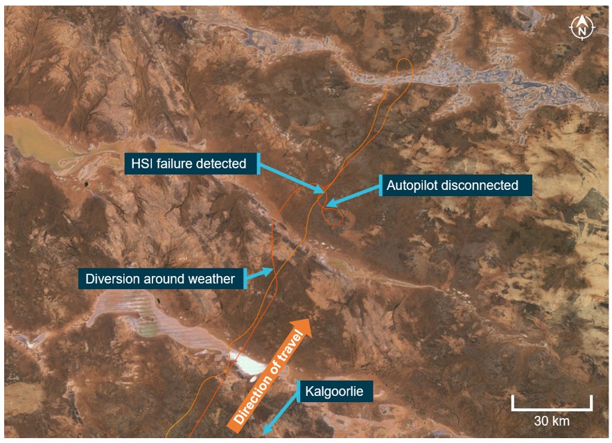
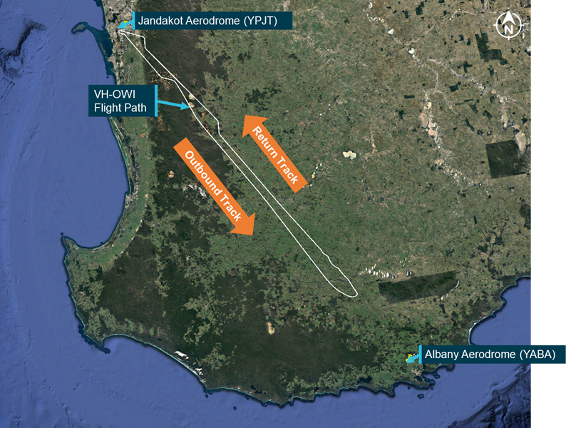
The ATSB is investigating an avionics/flight instrumentation issue involving a Rex Airlines Saab 340B, VH-ZRM, 3 km north-north-east of Townsville Airport, Queensland, on 19 November 2025.
During initial climb, the crew detected a fault with the flight management system (FMS), and the aircraft subsequently did not adhere to the tracking requirements of the standard instrument departure (SID).
The draft report internal review process has been completed. The draft report has been distributed to directly involved parties (DIPs) to check factual accuracy and ensure natural justice. Any submissions from those parties will be reviewed and, where considered appropriate, the draft report will be amended accordingly.
Following the external review process, any submissions and amendments to the draft report are internally reviewed. Once approved, the final report is prepared for publication and dissemination and released to DIPs prior to its public release.
The final report will be released at the conclusion of the investigation. Should a critical safety issue be identified during the course of the investigation, the ATSB will immediately notify relevant parties, so that appropriate safety action can be taken.
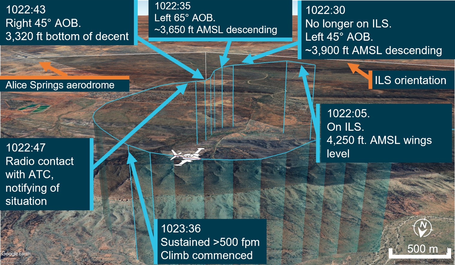
At around 1830 on 10 February 2025, a Sharp Airlines Fairchild SA227, registered VH‑UZN, was being prepared for a freight operations flight from Townsville Airport to Brisbane Airport, Queensland, with 2 crew on board.
The captain conducted an undocumented abbreviated external inspection of the aircraft. Around the same time, the first officer removed engine bungs and static port covers, however, could not reach the pitot tube covers located on the nose of the aircraft. This was communicated to the captain, who advised they would remove them, however, the captain subsequently forgot.
During the take-off run, both crew members recognised that the airspeed indicators were rising slower than anticipated, however, by this time, the captain was uncertain if there was sufficient runway remaining to safely stop the aircraft and elected to continue the take-off. During the climb, the first officer identified that the pitot tube covers have been left installed on the pitot tubes, which they announced to the captain. The crew then returned the aircraft to Townsville for an uneventful landing.
What the ATSB found
The ATSB found that due to a combination of a memory lapse and incorrect assumption the pitot tube covers were not removed prior to departure. It was also identified that the operator’s expectation as to what external aircraft inspection was required prior to this flight was not clearly stated in the procedures. In addition, the operator’s expectation that crews would fit pitot tube covers when the aircraft was unattended on the ground for 60 minutes or longer was inconsistent with its written procedures.
Further, the external security check, required to be completed prior to every flight, did not include ensuring the pitot tube covers had been removed.
Finally, the flight crew did not recognise that slow rising airspeed indications was symptomatic of blocked pitot tubes and, as a result, did not reject the take-off.
What has been done as a result
Sharp Airlines advised that it was reviewing the company standard operating procedures to ensure clarity of process for pre-flight inspections.
Safety message
This occurrence highlights the importance of conducting an airspeed check early in the take-off run and recognising that if this is not as expected that the take-off should be rejected. Flight crews should be aware of the typical symptoms associated with a blocked pitot tube, and that the airspeed may slowly increase.
The occurrence also illustrates the importance of procedures clearly stating what inspections are required and when. Flight crew pre-flight inspections are an important risk control. If inspections are not done correctly, it increases the risk of defects not being identified and/or the aircraft not being correctly configured for flight.
The occurrence
Background
This incident occurred on 10 February 2025, however, due to a reported administrative error, the ATSB was not advised until 18 July 2025. The ATSB subsequently commenced an investigation on that day. As the interviews with the flight crew were conducted 5 months after the occurrence, their recollection of the occurrence was degraded.
Pre-flight
At around 1830 local time on 10 February 2025, a Sharp Airlines Fairchild SA227-DC Metro 23, registered VH-UZN, was being prepared for a freight flight from Townsville Airport to Brisbane Airport, Queensland with 2 crew on board.
The operator’s freight flights were usually conducted as a single-pilot operation, however, due to the aircraft’s autopilot being unserviceable, 2 flight crew were required to operate the aircraft. As such, the captain and first officer (FO), who normally conducted regular public transport operations, were relocated to Queensland for one week, to conduct freight operations.
Both crew members signed on for duty that morning at 0100 in Brisbane and signed off at 0818 in Townsville, where they spent the day resting in a hotel room. They re‑commenced the shift shortly after 1800 to operate the Townville to Brisbane sector. All of the flight planning had been completed during the first duty, so the crew reassessed the conditions to ensure nothing had changed. The preparation for the flight, including the inspection of the aircraft, was conducted just prior to last light with no visibility restriction.
It was the captain’s responsibility to conduct or allocate the pre-flight external inspection (see the section titled External inspections). They advised that, as they had flown the aircraft earlier that day, a daily inspection had already been completed, and a crew change inspection (see the section titled Crew change inspection) was not required.
Instead, the captain advised they conducted an abbreviated inspection, which they did not discuss with the FO. The FO advised that they had flown with the captain on a few occasions previously and the captain had always conducted the pre-flight inspection, and they expected this to occur on this day.
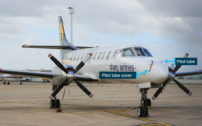
Regardless, to assist the captain, as they had done on previous days, the FO commenced some of the pre-flight tasks by removing the engine bungs and static port covers and preparing the aircraft for the aircraft loaders to arrive. They were unable to reach the pitot tube covers on the top of the nose cowl of the aircraft (Figure 1). The FO reported that they normally used a portable step, that was available in the passenger transport aircraft, to remove the pitot tube covers. However, the step was not available in the freight configuration aircraft.
In addition, they could not reach a ladder that was stowed in the rear locker as it had moved to the far side of the locker during flight. They placed the engine bungs and static port covers into a bag that they then placed on the ground beside the forward cargo hold, to remain until the pitot tube covers were removed and also placed in the bag.
Figure 1: Pitot tubes on Fairchild SA227
Source: EastWest Aviation, annotated by the ATSB
The captain was inside the aircraft completing pre-flight paperwork when the FO entered the aircraft and advised them that they could not reach the pitot tube covers. The captain acknowledged this and advised they would remove them.
There were delays of around 30 minutes while the crew waited for the aircraft loading to be completed. During this time, it had started raining heavily and became dark. The FO noticed that the bag containing the bungs and static covers was filling with water from the rain. In response, they retrieved the bag and placed it into the forward locker, observing ‘remove before flight’ tags in the bag.
Only aircraft operating at the Brisbane base had static port covers that also had ‘remove before flight’ tags attached, which the FO advised were identical to the tags attached to the pitot tube covers. As such, the FO, seeing the ‘remove before flight’ tags, presumed the captain had removed the pitot tube covers and placed them in the bag.
There were then further delays as the aircraft required reloading, and the captain was required to recalculate the manual trim configuration for the aircraft. The captain later stated feeling frustrated by the loading delays and that they likely felt some self-induced time pressure to depart, to avoid the worst of the incoming weather. They also later advised the operator that due to the heat and humidity, they did not wear the rain jacket provided, which may have influenced them not wanting to be outside the aircraft longer than necessary.
Once loading was complete and the aircraft was ready for departure, in accordance with company procedure, the FO commenced the final external security check (see the section titled External security check) which included a ‘4,3,2,1 check’ (see the section titled 4321 check). This check did not require that they inspect the pitot tubes to ensure the covers had been removed.
As the FO returned to the entry door, the captain stepped outside the aircraft. The FO incorrectly presumed that the captain was going to inspect the aircraft. However, neither crew discussed the external inspection, nor the final 4,3,2,1 check, prior to closing the aircraft’s main door.
Flight
The crew reported that as the aircraft commenced taxiing the heavy rain continued and it was very difficult to see out the front of the aircraft, and they did not detect the pitot tube covers. The crew reported that they completed all the required procedures prior to lining up on the runway including, as part of the ice protection and ignition step, selecting the pitot heat to ON.
During the initial stage of the take-off run, the captain set take-off power and then the FO took control of the aircraft (see the section titled Flight crew responsibilities during take‑off). At this time, the FO checked the airspeed, expecting to see it around 80 kt, but noted that it was fluctuating around 60–70 kt. The FO referenced the left side airspeed indicator, which also appeared to be fluctuating below 80 kts, quickly assessed how much runway was remaining, and called words to the effect of ‘Airspeed. Reject’.
Around the same time, the captain had also observed that their airspeed was indicating lower than they expected, and when the FO made the ‘reject’ call, they looked at the GPS unit which was indicating around 100–110 kt groundspeed. Noting there was minimal wind, the captain believed the GPS unit to be reasonably accurate and felt that the aircraft was ready to rotate.
Taking into consideration the wet runaway and not being sure how much runway was left due to the limited visibility, the captain made the decision to continue the take-off as they considered it was safer rather than risk running off the end of the runway. The captain called words to the effect of, ‘too fast, we’re going’.
During the initial climb, the FO heard a flapping noise coming from the front of the aircraft and identified that the pitot tube covers had been left installed on the pitot tubes, which they announced to the captain.
The FO referenced the GPS for speed to continue the climb and, shortly after, the FO’s airspeed indicator appeared to return to normal operation as it was indicating consistent with the GPS speed.
The crew discussed the situation and decided to return to Townsville Airport. The FO remained pilot flying due to having an operable airspeed indicator, while the captain contacted air traffic control (ATC) requesting a return to Townsville due to a technical problem. ATC provided radar vectors for the return, and the FO landed the aircraft uneventfully at 1958.
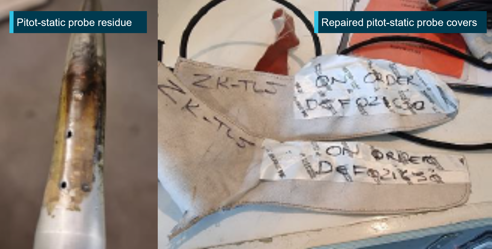
Following the post-flight inspection, the operator reported that the captain’s side pitot cover was mostly intact, and heat fused to the pitot tube. The FO’s side pitot cover had disintegrated, and the remnants of the cover had slid down to the rear of the pitot tube such that it did not obstruct normal operation.
Context
Flight crew details
The captain held a Commercial Pilot License (Aeroplane) and a class 1 aviation medical certificate. They had accumulated 3,642 flight hours, including 3,424 on the SA227‑DC.
The first officer (FO) held a Commercial Pilot License (Aeroplane) and a class 1 aviation medical certificate. They had accumulated around 5,000 flight hours, including 854 hours on the SA227-DC.
Analysis was undertaken to determine if fatigue was a factor which contributed to the captain forgetting to remove the pitot covers prior to departure. The time of day, crew work and rest patterns, and indicators of alertness were considered. The analysis concluded that the captain was unlikely to be experiencing fatigue at the time of the occurrence.
Due to the time that had passed between the incident and the crew being interviewed, the FO was unable to accurately recall their rest patterns in the days leading up to the occurrence. However, they advised that they felt rested and fit for duty.
Aircraft information
The Fairchild Swearingen SA227-DC is a low-wing, pressurised, twin-turboprop aircraft, manufactured in the United States in 1996 and issued serial number DC881B. It was registered in Australia as VH-UZN in 2005. The aircraft was fitted with 2 Garrett turbine TPE3311 engines.
The aircraft was fitted with a flight data recorder; however, the data was not downloaded by the operator at the time and had been overwritten when the ATSB was notified of the occurrence.
External inspections
The operator’s Flight crew operating manual (FCOM) stated there were 3 types of external inspections:
daily inspection (first flight of the day)
crew change inspection
post-flight inspection.
In addition, prior to closing the aircraft’s main door, both crew members were required to conduct a final security check, and the FO was required to do a ‘4321 check’.
Daily inspection
The operator’s Operations manual stated that:
A daily inspection is to be carried out as per the instructions in the Flight Crew Operating Manual for the aircraft type by the Pilot-in-Command or if he / she so delegates to, a person with the appropriate authority … on the first flight of the day for that aircraft.
The FCOM stated that the inspection consisted of an internal and external inspection. Further it stipulated (Figure 2) the path that flight crew should take when conducting the daily walk-around inspection. The numbers represent pause points to inspect a particular section of the aircraft, and each were associated with certain check items. One of the items to be checked was the condition of the pitot probes.
Figure 2: Schematic showing pre-flight walk-around path required prior to the first flight of the day
The crew change inspection was to be conducted whenever crew accepted an aircraft for duty and the aircraft had already flown that day.
The FCOM stated that:
It is not to be confused with a daily inspection. If an aircraft already operated by the crew has been taken offline for maintenance this inspection will be repeated. It consists of a Crew Change External Inspection and a Crew Change Internal Inspection. These inspections are similar to the Daily Inspection but omitting [first flight of the day] FFD items (unless that system had maintenance performed on it) and complete only hash (#) items on the internal component. Certification for the completion of this inspection was not required.
Among other items, the removal of bungs, pitot covers and wing tip flags was required as part of the crew change inspection.
External security check
In addition to the daily inspection (required for the first flight of the day), the FCOM required both crew members to conduct an external security check every flight, immediately prior to the cabin door being closed. This check comprised of the following:
• Check cargo and baggage is secure
• Tail stand (if fitted) is removed, stowed and pin retained
• All hatches, cowls and fuel caps closed
• Rotate the propellors to check for thermal distortion
• Check all ground equipment and the manoeuvring area is clear
4321 check
Prior to the cabin door being closed, the FO was also required to do an extra check, which the operator called a ‘4321 check’, and included:
Whilst standing at the front of the aircraft confirm with the “4,3,2,1 check” the following:
• 4 x doors latched and secure (excluding the main door at this stage)
• 3 x wheel chocks removed
• 2 x engine intakes and area underneath are clear, and 2 x fuel caps secure
• 1 x pogo stick (if fitted) removed.
Whilst this check is the RP [right pilot] responsibility, LP [left pilot] are not absolved from taking due care and diligence in this matter.
Post-flight inspection
The FCOM also set out the requirements for post-flight inspection. This was required to be conducted after each sector, and at the end of a duty period. The FCOM stated that after each sector the flight crew was required to, among other items:
• Ensure engine bungs, pitot covers and tail stand (if applicable) are in place.
An overview of the aircraft was to be conducted, checking the general condition and presence of any fluid (leaks or drips) on the aircraft or the adjacent ground.
Securing the aircraft
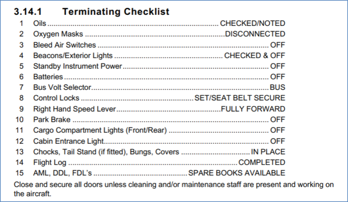
In addition to the post-flight inspection, the FCOM stated that on the last flight of the day, or if the aircraft was to be left unattended for greater than 60 minutes, the crew were required to secure the aircraft and conduct a terminating checklist (Figure 3). Securing the aircraft required the crew to:
• Ensure the A/C is parked correctly and in a safe secure area
• Ensure controls are locked (seat belt on last flight only)
• Chock all 3 landing gears.
• Tail stand in place (if fitted).
• Fit Engine Intake and Pitot covers (last flight only).
• Check cargo compartment lights (nose locker and rear) are off.
• Check for any fluid leaks under the A/C.
• Check tyres for wear and condition.
• Check all Beacons/Exterior Lights are serviceable.
• Complete and secure all Company Documentation (as appropriate).
• Complete a review of spare [Aircraft maintenance logs] AML, [Deferred defect list] DDL, [Flight deck log] FDL & ensure a spare book is available.
• Consult the TERMINATING Checklist when carrying out the above actions (Figure 3)
Despite the above list including the item ‘Fit engine intake and pitot covers (last flight only)’, Sharp Airlines later clarified that engine intake and pitot tube covers were expected to be fitted if the aircraft was left unattended for 60 minutes or more.
Sharp Airlines further advised that, although the first part of the duty was conducted on the same day, it expected that the flight crew should have conducted a full external (preflight) inspection, as a termination check had been completed at the end of the previous flight. However, the procedures did not state what checklist was required in this situation.
Flight crew responsibilities during take‑off
The captain (left pilot (LP)) was responsible for the take-off brief which included stating:
If prior to V1 you see anything that could adversely affect the safety of the flight clearly call “FAILURE” or clearly state “[the condition]”. I will decide whether to continue or reject the take-off by clearly stating either “CONTINUE” or “REJECT”
For a right pilot (FO) take-off the FCOM stated that:
• The LP advances the power levers to approx. 25–40% [torque] TQ whilst holding the aircraft on the brakes (paved surfaces only) and checks the BETA lights are off and calls [continuous alcohol water injection] “CAWI ON” (if CAWI required).
• The LP (Captain) observes the increase in TQ and the AWI pump lights are on (if CAWI required). Sets the power levers at 3% below required TQ calls “HANDING OVER” at approx. 60kts (ensure [nose wheel steering] NWS is released) and then calls “POWER SET” and leaves their hand on top of the power levers until V1.[1]
• RP responds, “TAKING OVER” and his/her hands remain clear of the power levers.
• LP Constantly scans the instruments for an impending failure or abnormality and calls “80kts”.
Sharp Airlines’ policy was that between 80 kt and V1 the take-off would only be rejected if there was an engine failure, a fire or the aircraft was otherwise unsafe or unable to fly.
Pitot static system
Pitot tubes
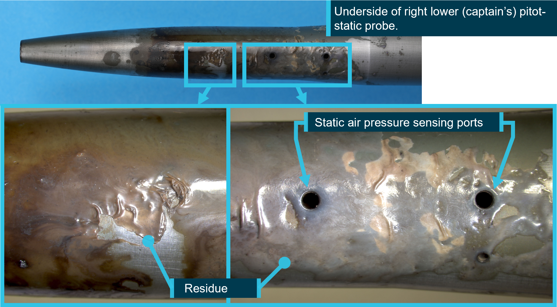
Pitot tubes are components of the aircraft’s pitot-static system. The Fairchild SA227-DC has 2 pitot tubes, which are attached to the upper cowl of the aircraft’s nose (Figure 1). The pitot tubes point directly into the airflow, measuring the total air pressure. This information and the static pressure, delivered by static ports on the fuselage, are used to compute the aircraft’s indicated airspeed. If the pitot tube is partially or completely blocked, airspeed indications will be inaccurate.
The pitot tubes have a heating system to prevent ice build-up. This is required to be selected ON prior to entering known icing conditions. The weather information from the Bureau of Meteorology for the time of the flight indicated that icing conditions were forecast above 10,000 ft. This required that the pitot heat was selected ON prior to take‑off.
Pitot tube covers
Pitot tube covers provide protection from foreign object obstruction when the aircraft is on the ground. They typically incorporate a ‘remove before flight’ warning tag/streamer (also known as a flag or ribbon) intended to alert relevant personnel of their presence.
Flight data
Take-off and landing data was not retained by the crew or the operator post-incident, however, the operator provided a recreated take-off and landing data (TOLD) card, with V1 calculated to be 114 kts.
The ADS-B flight data available to the ATSB had limited data points and parameters. During the take-off run, the recorded data periodicity was approximately 20 seconds, and this restricted an accurate estimation of the take-off location and groundspeed of the aircraft.
This data was compared to historical recorded flight data of 19 take-offs of another SA227-DC aircraft from Townsville Airport runway 01. Comparing the pitch attitude and indicated airspeed parameters in the historical data against the available ADS-B parameters for the flight, the ATSB was able to identify an approximate rotation location on runway 01 during the incident flight (Figure 4).
Figure 4: Estimated rotation location VH-UZN from historical flight analysis
Source: Google Earth using ADS-B exchange data, annotated by the ATSB
The ATSB estimated that the rotation speed (VR)[2] of VH-UZN, based on historical flights, was likely in the lower range of values between 112–130 kt.
Related occurrences
The ATSB has investigated several occurrences where ground use equipment has been left on aircraft due to inadequate flight crew inspections and/or inadequate operator guidance.
Airspeed indication failure on take-off involving Airbus A330 (AO-2018-053)
On 18 July 2018, a Malaysia Airlines Airbus A330, took off on a regular public transport flight from Brisbane, Queensland, to Kuala Lumpur, Malaysia. As the covers had been left on the aircraft’s 3 pitot probes, the instruments showed a red speed flag in place of the airspeed indication from early in the take-off, and unrealistically low airspeeds afterwards. The flight crew did not respond to the speed flags until the aircraft’s speed was too high for a safe rejection of the take-off, and the take-off was continued.
Aircraft preparation event involving Link Airways Saab 340 (AO-2022-055)
A propeller strap became embedded in a Link Airways Saab 340B regional airliner’s cabin on take-off from Canberra in November 2022. The ATSB’s investigation found that several factors contributed to the propeller strap not being noticed or removed by the first officer, captain, or dispatcher, prior to departure, including that the guidance provided by Link Airways for training of Swissport dispatchers did not explain the appearance, function and importance of the propeller strap.
Aircraft preparation event involving Saab 340B (AO-2022-058)
On 16 November 2022, a Regional Express (Rex) Saab 340B, was prepared for a scheduled air transport flight from Cairns Airport to Bamaga, Queensland. As the crew taxied the aircraft to the runway, an engineer on a nearby parking bay noticed something hanging from the aircraft and contacted the tower. The crew returned the aircraft to the bay. Aircraft parked overnight at Cairns were required to be fitted with an operator designed bung installed in the horizontal stabiliser trim actuator cove to prevent bird nesting. The inspection revealed the horizontal stabiliser bungs had not been removed and were still installed in the left trim actuator cove.
Aircraft preparation event involving a Hawker Beechcraft Corporation B200 (AB-2024-025)
On 8 May 2024, a Hawker Beechcraft B200 was being prepared for an air transport flight at Darwin Airport. Prior to departure, the pilot completed the preflight inspection, confirmed that both red flags were in their possession, and secured these items along with the propeller covers inside the aircraft. However, the pilot did not detect that the flag for the right-side cover had detached from the cover, nor that the cover was still attached to the pitot tube.
During the take-off, the pilot detected a speed discrepancy on their cockpit instrumentation. They continued the climb to 3,000 ft before returning via a visual approach to Darwin Airport.
During the post-flight inspection, the pilot identified that the right-side pitot cover was still in place, covering the pitot tube.
Aircraft preparation event involving Saab 340B (AO-2024-059)
On 19 November 2024, the aircraft was prepared for departure from Melbourne Airport. After the pilots started the engines, a passenger told the flight attendant they had seen a strap restraining the left propeller before it began to spin. The propeller strap was then found attached to the propeller, with the pins that connect it to the engine cowling broken on start‑up.
The report noted the final external walkaround check of the aircraft required the first officer to remove the propeller strap from the propeller, before rotating the propeller to a required position. However, the first officer inadvertently left the propeller strap attached, instead only disconnecting and removing the strap extension, which connected the propeller strap to the aircraft stairs to prevent them from being retracted while the strap is in place.
Once the first officer was in the flight deck, the ground handler assigned to the dispatch, who was a trainee, did not detect the propeller strap from their position at the nose of the aircraft, and provided the crew with a signal to start the engine.
Meanwhile, the pilots conducted the engine start checklist, which included a requirement for the captain to check that the left engine was clear. The captain also did not detect the propeller strap and proceeded to start the engine.
Safety analysis
A Sharp Airlines Fairchild SA227 departed Townsville Airport with pitot tube covers fitted. This analysis will discuss the pre-flight actions of the flight crew regarding the pitot tube covers and consider the operator’s procedures for pre-flight inspections. It will further examine the crew’s decision to take-off with unreliable airspeed.
Pre-flight inspection
The captain considered that the daily inspection had already been completed in the early hours of the morning on the previous sector, and therefore, it was not required to be completed prior to this flight. They also did not consider that a crew change external inspection was required. Consequently, they reportedly conducted an abbreviated walk‑around inspection prior to the incident flight but did not reference any aircraft or operator checklist.
The first officer (FO) assisted the captain by removing the engine bungs and static port covers. However, they were unable to reach the pitot covers on the nose of the aircraft and asked the captain to remove them. The captain advised that they would do so, but subsequently forgot. Additionally, the FO did not confirm with the captain that the pitot covers had been removed, likely due to seeing ‘remove before flight’ tags in the bag and incorrectly assuming those were attached to the pitot covers.
There was no further discussion between the captain and the FO regarding the external aircraft inspection, and the pitot covers were not removed prior to departure.
Contributing factor
Due to the combination of a memory lapse and incorrect assumption, the aircraft’s pitot covers were not removed prior to departure.
Operator’s guidance
The operator’s Flight crew operating manual (FCOM) required flight crews to secure the aircraft and conduct a terminating check if the aircraft was to be unattended for more than 60 minutes. While it was the operator’s expectation that a full daily inspection of the aircraft was required once a termination check had been completed; the procedures did not clearly state this, and it did not occur on this occasion.
The operator did have an abbreviated checklist, the crew change checklist, and it is possible some flight crew were conducting this checklist on returning to the aircraft after completing the terminating check, however, the procedures also did not specify that this was required.
In addition, the operator also expected that engine bungs and pitot covers would be fitted when the aircraft was on the ground for periods over 60 minutes; however, the procedure (securing the aircraft) specifically stated that they should be fitted only after the last flight. This created the potential for confusion among flight crew as to when they should be fitted.
Further, while the final ‘4321’ visual check was designed for quick turnarounds, it required that the engine intakes were checked, and although engine bungs were only required to be installed when the pitot tube covers were installed, it did not require that the pitot tube covers were checked.
a terminating check be completed if the aircraft was unattended for more than 60 minutes, but did not specify what checks were to be completed on return to the aircraft
pitot covers should be installed after the last flight of the day only, where the operator required that they be installed if the aircraft was unattended for longer than 60 minutes.
In addition, the final visual check, completed by the first officer prior to closing the doors, did not include checking that pitot covers had been removed. (Safety issue)
Poor visibility
It is likely that due to the night‑time conditions and heavy rain, neither flight crew detected the pitot covers in place, as they would have during the day, while taxiing the aircraft.
Similarly, there was no opportunity for air traffic control, other pilots or ground staff to visually observe the pitot tube covers in place. As such, the pitot tube covers remained in place undetected.
Contributing factor
Likely due to poor visibility, the flight crew did not detect the pitot tube covers were still in place prior to commencing the take-off.
Airspeed indications during take-off
The captain's decision to take off once the crew recognised that the airspeed was unreliable was understandable in the circumstances, and probably at, or close to V1. However, there was opportunity for the crew to have recognised earlier in the take-off run that the airspeed indicators were not functioning correctly, as the speeds were slowly increasing. Continuation of the take-off was likely due in part to neither crew realising that airspeed could still increase with pitot covers on.
Contributing factor
During the take-off run, the crew did not detect that the airspeed indicators were not indicating correctly, likely due to observing that they were slowly increasing, resulting in the crew not rejecting the take-off.
Findings
ATSB investigation report findings focus on safety factors (that is, events and conditions that increase risk). Safety factors include ‘contributing factors’ and ‘other factors that increased risk’ (that is, factors that did not meet the definition of a contributing factor for this occurrence but were still considered important to include in the report for the purpose of increasing awareness and enhancing safety). In addition ‘other findings’ may be included to provide important information about topics other than safety factors.
Safety issues are highlighted in bold to emphasise their importance. A safety issue is a safety factor that (a) can reasonably be regarded as having the potential to adversely affect the safety of future operations, and (b) is a characteristic of an organisation or a system, rather than a characteristic of a specific individual, or characteristic of an operating environment at a specific point in time.
These findings should not be read as apportioning blame or liability to any particular organisation or individual.
From the evidence available, the following findings are made with respect to the unreliable airspeed indications on 10 February 2025:
Contributing factors
Due to the combination of a memory lapse and incorrect assumption, the aircraft’s pitot covers were not removed prior to departure.
- a terminating check be completed if the aircraft was unattended for more than 60 minutes, but did not specify what checks were to be completed on return to the aircraft
- pitot covers should be installed after the last flight of the day only, where the operator required that they be installed if the aircraft was unattended for longer than 60 minutes.
In addition, the final visual check, completed by the first officer prior to closing the doors, did not include checking that pitot covers had been removed. (Safety issue)
Likely due to poor visibility, the flight crew did not detect the pitot tube covers were still in place prior to commencing the take-off.
During the take-off run, the crew did not detect that the airspeed indicators were not indicating correctly, likely due to observing that they were slowly increasing, resulting in the crew not rejecting the take-off.
Safety issues and actions
Central to the ATSB’s investigation of transport safety matters is the early identification of safety issues. The ATSB expects relevant organisations will address all safety issues an investigation identifies.
Depending on the level of risk of a safety issue, the extent of corrective action taken by the relevant organisation(s), or the desirability of directing a broad safety message to the aviation industry, the ATSB may issue a formal safety recommendation or safety advisory notice as part of the final report.
All of the directly involved parties were provided with a draft report and invited to provide submissions. As part of that process, each organisation was asked to communicate what safety actions, if any, they had carried out or were planning to carry out in relation to each safety issue relevant to their organisation.
Descriptions of each safety issue, and any associated safety recommendations, are detailed below. Click the link to read the full safety issue description, including the issue status and any safety action/s taken. Safety issues and actions are updated on this website when safety issue owners provide further information concerning the implementation of safety action.
a terminating check be completed if the aircraft was unattended for more than 60 minutes, but did not specify what checks were to be completed on return to the aircraft
pitot covers should be installed after the last flight of the day only, where the operator required that they be installed if the aircraft was unattended for longer than 60 minutes.
In addition, the final visual check, completed by the first officer prior to closing the doors, did not include checking that pitot covers had been removed.
Glossary
ATC
Air traffic control
FO
First officer
FCOM
Flight crew operating manual
GPS
Global positioning system
TOLD
Take off and landing data
V1
The critical engine failure speed or decision speed required for take-off. Engine failure below V1 should result in a rejected take off; above this speed the take-off should be continued. In this aircraft, V1 and VR are the same value.
VR
The speed at which the rotation of the aircraft is initiated to take-off attitude.
Sources and submissions
Sources of information
The sources of information during the investigation included the:
flight crew of the incident flight and another pilot who conducted flights for the operator
Sharp Airlines
ADS-B data.
References
Sharp Airlines, Metro 3/23 Flight Crew Operating Manual, Issue 09, Revision 2, 24 June 2024
Under section 26 of the Transport Safety Investigation Act 2003, the ATSB may provide a draft report, on a confidential basis, to any person whom the ATSB considers appropriate. That section allows a person receiving a draft report to make submissions to the ATSB about the draft report.
A draft of this report was provided to the following directly involved parties:
flight crew of incident flight
Sharp Airlines
Civil Aviation Safety Authority.
No submissions were received.
Purpose of safety investigations
The objective of a safety investigation is to enhance transport safety. This is done through:
identifying safety issues and facilitating safety action to address those issues
providing information about occurrences and their associated safety factors to facilitate learning within the transport industry.
It is not a function of the ATSB to apportion blame or provide a means for determining liability. At the same time, an investigation report must include factual material of sufficient weight to support the analysis and findings. At all times the ATSB endeavours to balance the use of material that could imply adverse comment with the need to properly explain what happened, and why, in a fair and unbiased manner. The ATSB does not investigate for the purpose of taking administrative, regulatory or criminal action.
About ATSB reports
ATSB investigation reports are organised with regard to international standards or instruments, as applicable, and with ATSB procedures and guidelines.
Reports must include factual material of sufficient weight to support the analysis and findings. At all times the ATSB endeavours to balance the use of material that could imply adverse comment with the need to properly explain what happened, and why, in a fair and unbiased manner.
An explanation of terminology used in ATSB investigation reports is available here. This includes terms such as occurrence, contributing factor, other factor that increased risk, and safety issue.
Publishing information
Released in accordance with section 25 of the Transport Safety Investigation Act 2003
Ownership of intellectual property rights in this publication
Unless otherwise noted, copyright (and any other intellectual property rights, if any) in this report publication is owned by the Commonwealth of Australia.
Creative Commons licence
With the exception of the Commonwealth Coat of Arms, ATSB logo, and photos and graphics in which a third party holds copyright, this report is licensed under a Creative Commons Attribution 4.0 International licence.
The CC BY 4.0 licence enables you to distribute, remix, adapt, and build upon our material in any medium or format, so long as attribution is given to the Australian Transport Safety Bureau.
Copyright in material obtained from other agencies, private individuals or organisations, belongs to those agencies, individuals or organisations. Where you wish to use their material, you will need to contact them directly.
[1]V1: the critical engine failure speed or decision speed required for take-off. Engine failure below V1 should result in a rejected take off; above this speed the take-off should be continued. In this aircraft, V1 and VR are the same value.
[2]VR: the speed at which the rotation of the aircraft is initiated to take-off attitude.
On 18 June 2025, a Beechcraft King Air B200, registered VH-EEL, was on descent into Bankstown Airport, New South Wales, on a passenger transport flight with the pilot and 4 passengers on board when the pilot heard a whistling noise followed by the sound of an impact coming from the rear of the aircraft. There were no abnormal indications and the aircraft was flying normally, so the pilot continued the flight.
Shortly after, the pilot was unable to reach air traffic control via radio and switched to the aircraft’s alternative radio. Communication was re‑established and the aircraft landed safely. An external inspection of the aircraft found that the VHF antenna on top of the fuselage was missing, and the vertical stabiliser was damaged.
What the ATSB found
While the top of the antenna was not recovered, the aluminium antenna base showed evidence of moisture ingress. This resulted in the antenna failing and separating from the aircraft. The exact failure mechanism could not be determined – moisture could have been absorbed by the composite skin of the antenna, reducing its strength. Alternatively, observed corrosion could have weakened the bond between structural components within the antenna, reducing stiffness and allowing cracks to develop.
Safety message
While it is not clear whether pre-existing damage was observable during antenna inspections, this occurrence is a useful reminder on the importance of vigilance while conducting routine maintenance. In addition, it serves to demonstrate the value of redundancy in safety-critical systems.
The investigation
The ATSB scopes its investigations based on many factors, including the level of safety benefit likely to be obtained from an investigation and the associated resources required. For this occurrence, the ATSB conducted a limited-scope investigation in order to produce a short investigation report, and allow for greater industry awareness of findings that affect safety and potential learning opportunities.
The occurrence
On the afternoon of 18 June 2025, a Beechcraft King Air B200, registered VH-EEL, departed from Dubbo Airport, New South Wales, on a passenger transport flight to Bankstown Airport. The flight was operated by CJ Aerospace with the pilot and 4 passengers on board. It was a clear day and the aircraft was flying in visual meteorological conditions.
At approximately 1523, the aircraft was about 30 NM (55 km) from Bankstown Airport and descending through 11,000 ft when the pilot heard a whistling noise coming from the back of the aircraft. After a few seconds, the pilot reported hearing the sound of an impact towards the rear of the aircraft. The aircraft’s airspeed was approximately 280 kt at the time. There were no abnormal indications in the cockpit and the aircraft was flying normally, so the pilot continued with the flight.
The aircraft had been previously cleared by air traffic control (ATC) to descend to 5,000 ft. However, after reaching this altitude it had not been cleared for further descent, which the pilot noted to be unusual. The pilot conducted a radio check with ATC but received no response. The pilot switched the aircraft’s active VHF radio from COM 1 to COM 2, and contact with ATC was subsequently re‑established. The rest of the approach and landing proceeded without incident and the aircraft landed at Bankstown Airport at 1534.
After landing, the pilot conducted an external inspection of the aircraft and found that the VHF antenna on top of the fuselage was missing, and the vertical stabiliser was damaged (Figure 1). Further information on the damage is in Aircraft information and Antenna examination.
Figure 1: Damage to the vertical stabiliser
Source: Jet Aviation
Context
Pilot information
The pilot held a Commercial Pilot (Aeroplane) Licence, issued in December 2019, with a multi‑engine aeroplane instrument rating. At the time of the occurrence, the pilot had approximately 1,980 hours total flying experience, of which 140 hours were accrued on the King Air B200.
Aircraft information
The Beechcraft King Air B200 is a pressurised, low-wing, twin turbine-engine aircraft. It has 2 VHF antennas: COM 1 is fitted on top of the fuselage, and COM 2 is underneath the fuselage (Figure 2). VH-EEL was manufactured in the United States in 2000 and registered in Australia in the same year. CJ Aerospace had been the registered operator of the aircraft since July 2021.
Figure 2: VHF antennas on VH-EEL
Source: CQ Plane Spotting
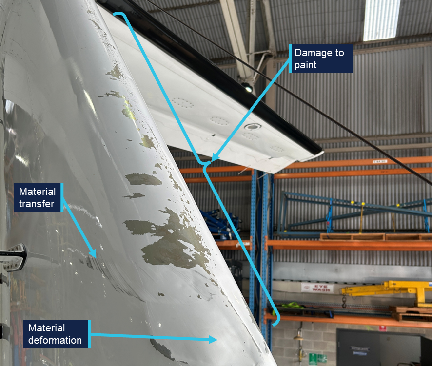
Aircraft examination
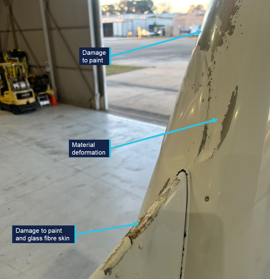
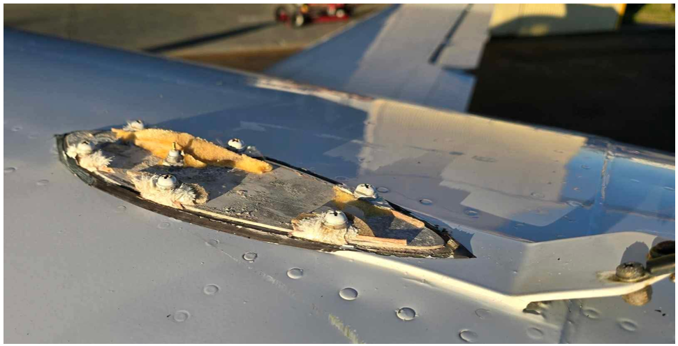
Following the occurrence, the aircraft was sent to a maintenance facility for examination and repair. The examination (not attended by the ATSB) identified that the leading edge of the vertical stabiliser had experienced deformation, and there was damage to the skin and paint on various parts of the empennage (Figure 3 and Figure 4). There also appeared to be some transfer of black material, possibly paint or rubber, onto the right side of the vertical stabiliser. The base of the antenna was still secured to the fuselage by 6 fasteners, but the glass fibre skin of the antenna had failed around each of the fasteners and separated from the aircraft (Figure 5).
Figure 3: Damage on the front of the empennage
Source: Jet Aviation, annotated by the ATSB
Figure 4: Damage on the right side of the empennage
Source: Jet Aviation, annotated by the ATSB
Figure 5: The antenna base still secured to VH-EEL
Source: Jet Aviation
Antenna examination
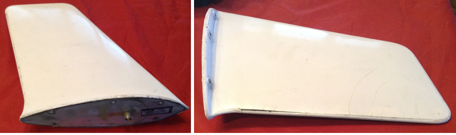
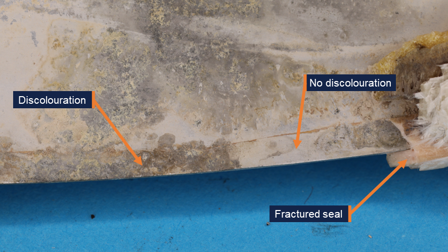
The detached antenna was not located. The antenna base was examined at the ATSB’s engineering facility in Canberra. The manufacturer’s label indicated that it was manufactured by the Trivec-Avant corporation. The part number was 18-40-01 and the serial number was 11514. The antenna was not original to the aircraft, and its installation date could not be determined. The Trivec-Avant corporation ceased operation in about 2011, and no technical drawings or other details could be obtained for the antenna. However, images of an antenna with the same part number were sourced online (Figure 6). It comprised a base and upper structure with an internal electrical antenna.
Figure 6: Exemplar VHF COM antenna
Source: majorjunque (eBay)
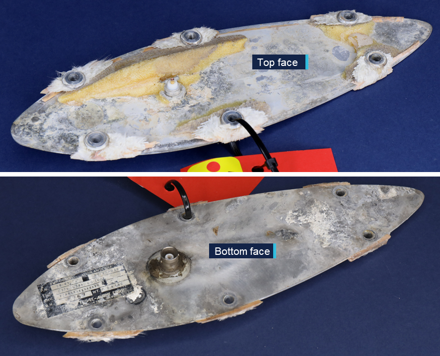
The antenna base from VH-EEL was an aluminium plate with 6 holes for fasteners and a central coaxial connection for the internal electrical antenna (Figure 7). A yellow foam adhered to the top face of the antenna was likely an expanding polyurethane product that was injected into the antenna during its construction in order to increase rigidity (Figure 8). Some fractured glass fibre composite material was observed around each of the fasteners. Fragments of a polymer seal were observed around the edges of the antenna base.
Figure 7: Antenna base from the aircraft
Source: ATSB
Both surfaces of the plate showed discoloration in several locations, identified as deposits on the surface of the metal (Figure 8). The deposits varied in colour. Samples of the dark-coloured and light-coloured deposits were scraped from the antenna using a plastic spatula and analysed for elemental composition using energy-dispersive X-ray spectroscopy (EDS). EDS analysis found that the composition of the light and dark deposits was very similar. Both predominantly contained aluminium, oxygen, and a smaller quantity of chlorine. The presence of chlorine indicated that the plate was exposed to salt water, resulting in corrosion of the aluminium plate, forming aluminium oxide.
Figure 8: Aft end of the antenna base, top face
Source: ATSB
The discolouration was not uniformly distributed over the base, and there were some regions, such as the one shown in Figure 8, where there was no evidence of deposits or discolouration. Similarly, while much of the base’s edge was discoloured, there were some regions underneath the polymer seal that appeared relatively unaffected (Figure 9).
Figure 9: Discolouration under the polymer seal, at the edge of the top face
Source: ATSB
Aircraft maintenance
The aircraft was maintained under a 4-phase inspection program over 800 flight hours or 24 calendar months. Each phase of routine maintenance was conducted sequentially every 200 hours. Inspection of the VHF antennas was conducted in Phase 3. The inspection required personnel to:
…inspect all external antennas for leading edge erosion and condition of base seals.
This was last performed on 18 October 2024 with no relevant findings recorded.
The aircraft manufacturer provided guidelines for corrosion control inspections, which were optional and to be used depending on the operating environment. Regarding antennas, the inspection stated the following:
ANTENNAS - Inspect antenna bases for proper sealing. Inspect antenna leading edges for severe erosion.
These inspections were also last carried out on 18 October 2024 with no relevant findings recorded.
Neither inspection specified whether antenna removal was necessary.
Similar occurrences
The aircraft manufacturer could not identify any previous instances of antenna separation in flight, but noted that ‘while it is rare, it is not unknown for antennas to crack at the fastener holes’.
Safety analysis
Based on the aluminium oxide and chlorine found on the surface of the VHF antenna base – a part of the antenna that should be fully enclosed and sealed – the antenna failed in flight due to pre-existing damage resulting from corrosion. The corrosion was almost certainly due to moisture ingress into the unit.
Since most of the antenna was not recovered, there was no way to determine the pathway through which moisture entered the antenna. Most of the seal surrounding the base had separated with the top half of the antenna. There was evidence of moisture under the seal in some regions, while some parts of the seal appeared to have prevented corrosion. The moisture under the seal could indicate a point of ingress, but it is possible that all the corrosion observed under the seals was due to moisture already inside the antenna, rather than evidence that the seal had been compromised.
Beyond the fact that the antenna cracked around the 6 fastener holes, the exact failure mechanism could not be determined. It is possible that corrosion weakened the bond between the polyurethane core and the base or skin of the antenna. This would have reduced the stiffness of the unit, allowing cracks to develop as it flexed during service. Alternatively, moisture could have been absorbed by the glass fibre composite skin, reducing its strength and increasing susceptibility to cracking.
Without an understanding of the mechanisms that led to moisture entering the antenna and the subsequent in-flight separation, it is not possible to determine whether any damage would have been externally visible during the relevant inspection 8 months before the occurrence. Cracking around the fastener holes might not have commenced at that point. Alternatively, damage could have been too small to detect or obscured by the paint.
One alternative possibility to pre-existing damage could not be entirely ruled out: a birdstrike or collision with a remotely piloted aircraft (RPA) could have resulted in antenna separation. However, very few birdstrikes occur above 10,000 ft, and most RPAs are not certified to fly that high. No in-flight RPA loss was reported. There was also no visual evidence of a birdstrike, and any contact with bird or RPA would likely have resulted in a loud bang precipitating the occurrence, rather than a whistling sound followed by the sound of an impact.
Findings
ATSB investigation report findings focus on safety factors (that is, events and conditions that increase risk). Safety factors include ‘contributing factors’ and ‘other factors that increased risk’ (that is, factors that did not meet the definition of a contributing factor for this occurrence but were still considered important to include in the report for the purpose of increasing awareness and enhancing safety). In addition ‘other findings’ may be included to provide important information about topics other than safety factors.
These findings should not be read as apportioning blame or liability to any particular organisation or individual.
From the evidence available, the following findings are made with respect to the antenna failure involving Beechcraft King Air B200, VH-EEL, 55 km west of Bankstown Airport, New South Wales, on 18 June 2025.
Contributing factors
During flight, pre-existing damage due to moisture ingress resulted in the VHF COM 1 antenna failing and separating from the aircraft.
Sources and submissions
Sources of information
The sources of information during the investigation included:
the pilot
CJ Aerospace
Textron Aviation (Beechcraft)
the aircraft maintenance organisation
the maintenance organisation that examined the aircraft following the occurrence
Civil Aviation Safety Authority
Flightradar24.
Submissions
Under section 26 of the Transport Safety Investigation Act 2003, the ATSB may provide a draft report, on a confidential basis, to any person whom the ATSB considers appropriate. That section allows a person receiving a draft report to make submissions to the ATSB about the draft report.
A draft of this report was provided to the following directly involved parties:
the pilot
CJ Aerospace
the aircraft maintenance organisation
Civil Aviation Safety Authority
Textron Aviation (Beechcraft)
National Transportation Safety Board (United States).
There were no submissions received.
Purpose of safety investigations
The objective of a safety investigation is to enhance transport safety. This is done through:
identifying safety issues and facilitating safety action to address those issues
providing information about occurrences and their associated safety factors to facilitate learning within the transport industry.
It is not a function of the ATSB to apportion blame or provide a means for determining liability. At the same time, an investigation report must include factual material of sufficient weight to support the analysis and findings. At all times the ATSB endeavours to balance the use of material that could imply adverse comment with the need to properly explain what happened, and why, in a fair and unbiased manner. The ATSB does not investigate for the purpose of taking administrative, regulatory or criminal action.
About ATSB reports
ATSB investigation reports are organised with regard to international standards or instruments, as applicable, and with ATSB procedures and guidelines.
Reports must include factual material of sufficient weight to support the analysis and findings. At all times the ATSB endeavours to balance the use of material that could imply adverse comment with the need to properly explain what happened, and why, in a fair and unbiased manner.
An explanation of terminology used in ATSB investigation reports is available here. This includes terms such as occurrence, contributing factor, other factor that increased risk, and safety issue.
Publishing information
Released in accordance with section 25 of the Transport Safety Investigation Act 2003
Ownership of intellectual property rights in this publication
Unless otherwise noted, copyright (and any other intellectual property rights, if any) in this report publication is owned by the Commonwealth of Australia.
Creative Commons licence
With the exception of the Commonwealth Coat of Arms, ATSB logo, and photos and graphics in which a third party holds copyright, this report is licensed under a Creative Commons Attribution 4.0 International licence.
The CC BY 4.0 licence enables you to distribute, remix, adapt, and build upon our material in any medium or format, so long as attribution is given to the Australian Transport Safety Bureau.
Copyright in material obtained from other agencies, private individuals or organisations, belongs to those agencies, individuals or organisations. Where you wish to use their material, you will need to contact them directly.
Occurrence summary
Investigation number
AO-2025-031
Occurrence date
18/06/2025
Occurrence time and timezone
1523 Australian Eastern Standard Time
Location
55 km west of Bankstown Airport
State
New South Wales
Report release date
15/05/2026
Report status
Final
Investigation level
Short
Investigation type
Occurrence Investigation
Investigation phase
Final report: Dissemination
Investigation status
Completed
Mode of transport
Aviation
Aviation occurrence category
Avionics/flight instruments, Objects falling from aircraft
Occurrence class
Incident
Highest injury level
None
Aircraft details
Manufacturer
Raytheon Aircraft Company
Model
B200
Registration
VH-EEL
Serial number
BB-1697
Aircraft operator
C J Aerospace Pty Ltd
Sector
Turboprop
Operation type
Part 135 Air transport operations - smaller aeroplanes
Activity
Commercial air transport-Non-scheduled-Passenger transport charters
On 9 October 2024, VH-ZMW, a Beech Aircraft B200, was conducting an air transport flight with 6 persons on board, from Toowoomba to Normanton, Queensland. The aircraft departed and, approximately 30 minutes into the flight, entered a thunderstorm. The pilot diverted the aircraft to Roma, Queensland, where it was assessed by an engineer. The aircraft sustained minor damage, and the passengers and pilot were uninjured.
What the ATSB found
The ATSB found that although the pilot delayed the initial departure, reviewed the available weather information, and discussed their plan with more experienced colleagues, the aircraft entered a thunderstorm resulting in minor damage to the aircraft.
The ATSB also found that as the airborne weather radar had been incorrectly installed, its effectiveness at detecting cloud was reduced and was providing misleading information, which degraded the pilot's in-flight assessing and planning.
In addition, the pilot’s fuel planning using the company software included a fixed reserve that was less than the value detailed in the company’s exposition.
Finally, prior to departure the pilot informed the passengers of possible turbulence and kept the seatbelt sign on throughout the flight. This briefing and decision‑making likely contributed to the safety of the passengers when turbulence was experienced.
What has been done as a result
The operator rectified the incorrect installation of the weather radar. While the operator already provided weather radar theory training, it was not specific to the device installed on the aircraft. A Garmin training course is now provided to company pilots.
The flight planning software has also been reviewed to ensure the correct parameters are used as per the operator’s exposition.
Additionally, even though fatigue was not considered a safety factor, the operator has introduced a new fatigue reporting tool and monitoring system for rostering.
Safety message
This incident highlights how quickly weather conditions can change and, where possible, remaining visual can provide better identification of the weather. Using equipment such as airborne weather radar, can provide pilots with better situational awareness. However, the equipment is only useful if it is installed correctly, and the pilot has previously used and become knowledgeable with operating it before they’re required to use it to assist with navigating weather.
Areas of known weather should be avoided by 20 NM (37 km) and weather radar should not be used for penetrating areas of known weather. Instead, it should be used at longer range to plan around the precipitation returns.
The ATSB SafetyWatch highlights the broad safety concerns that come out of our investigation findings and from the occurrence data reported to us by industry.
Decisions regarding the scope of an investigation are based on many factors, including the level of safety benefit likely to be obtained from an investigation and the associated resources required. For this occurrence, a limited-scope investigation was conducted in order to produce a short investigation report, and allow for greater industry awareness of findings that affect safety and potential learning opportunities.
The occurrence
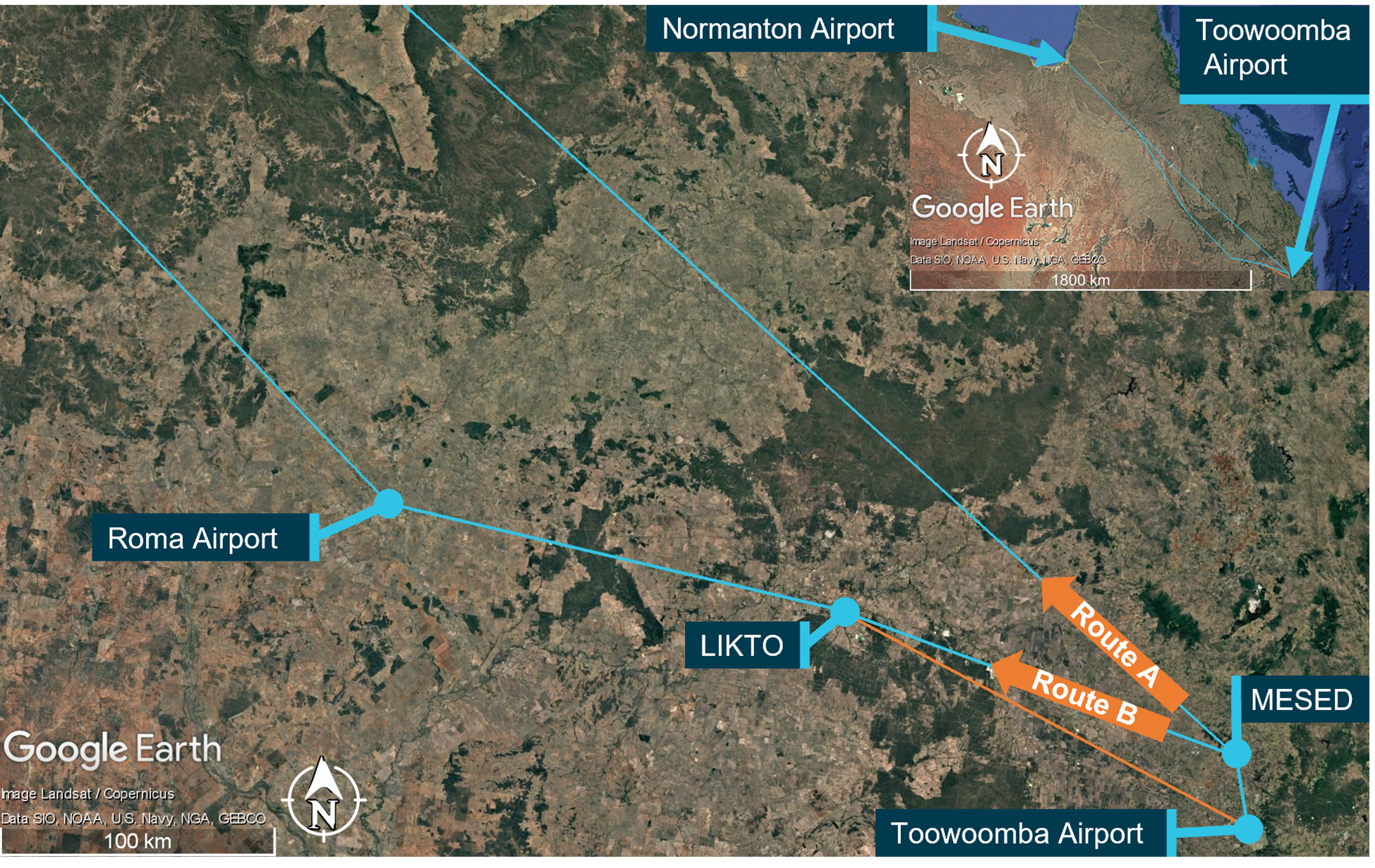
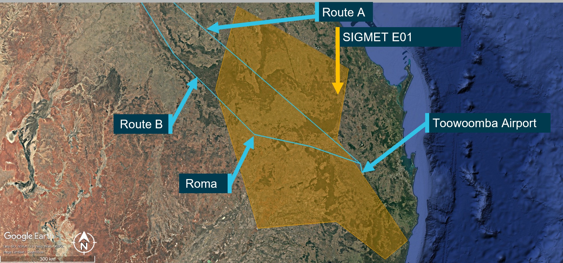
On 9 October 2024, a Beechcraft B200, registered VH-ZMW and operated by Austrek Aviation, was being prepared for a passenger transport flight with a pilot and 5 passengers from Toowoomba Airport to Normanton Airport, Queensland. At 1138 local time, the pilot submitted a flight plan to air traffic services for a direct route to Normanton (route A) (Figure 1), intending to depart at 1600.
During the pilot’s preparations, they identified that thunderstorm activity was likely along the intended flight path. Consequently, they reported accessing multiple weather forecasts and observations via their electronic flight bag (EFB), which was running a flight planning application. Additionally, they used the Bureau of Meteorology weather radar to obtain an indication of likely thunderstorm activity in the area. The pilot also reported discussing the weather with their more experienced colleagues. At 1517, they revised the flight plan to route B, to overfly Roma Airport and then to Normanton, which was assessed as a more suitable route around the thunderstorm activity.
Figure 1: Planned flight routes
Source: Flight route submission provided by AirServices Australia, recreated and annotated by the ATSB overlaid on Google Earth
The pilot delayed departure due to a passing thunderstorm in the vicinity of Toowoomba. The pilot advised that prior to departure at 1620, they provided a briefing to the passengers, which included the possibility of encountering turbulence. Additionally, they kept the seatbelt sign on throughout the flight.
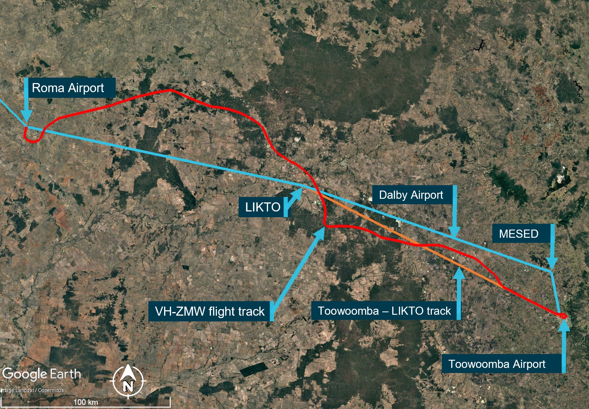
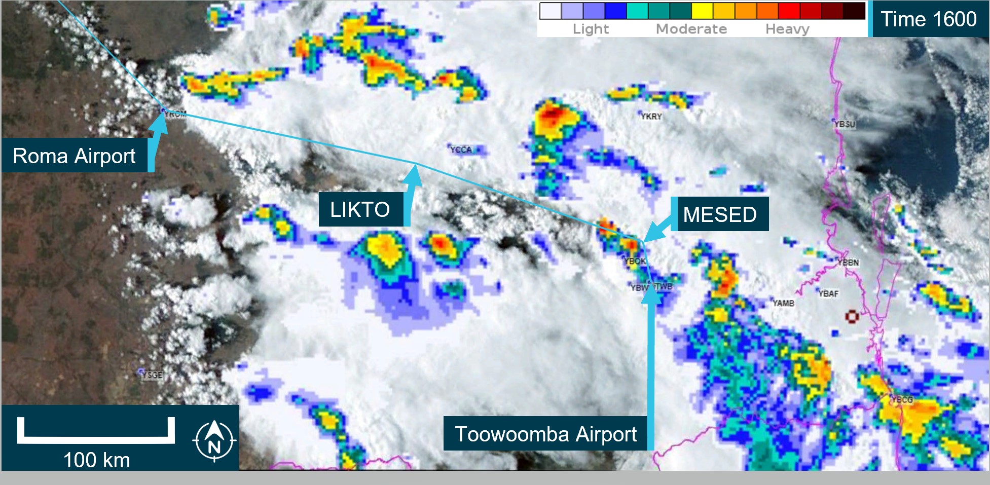
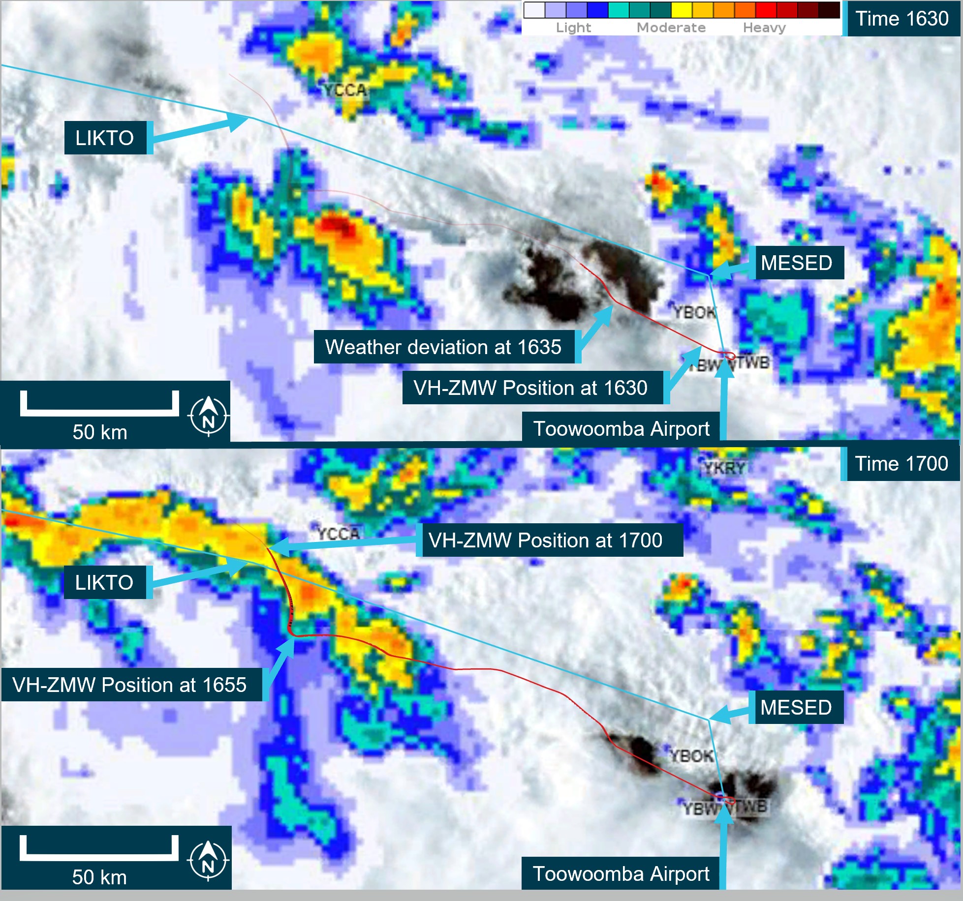
At 1624, the pilot reported to air traffic control (ATC) that they were taxiing for departure at Toowoomba. The controller advised that the pilot of another aircraft, approximately 20 NM (37 km) north‑west of Toowoomba, was currently deviating around multiple cloud build-ups[1] and asked what their intentions on departure were concerning the deteriorating weather in the area. The pilot opted to further revise their flight plan at this time and requested to fly directly to LIKTO waypoint[2] (Figure 1) rather than tracking north to the MESED waypoint as planned. Additionally, they advised that they would initially level at an altitude of 4,000 ft to remain clear of cloud until they could climb without entering it. On departure, the pilot estimated they would reach LIKTO at 1654.
At 1634, approximately 20 NM (37 km) north-west of Toowoomba, passing 10,900 ft on climb and clear of cloud, the pilot requested and received clearance to deviate 10 NM (18.5 km) right and left of the flight plan track to avoid cloud. They then turned onto a more northerly heading (Figure 2). The pilot later reported that they were able to maintain visual conditions up to the intended cruise level of FL 240.[3] Reaching FL 240 at 1645, the pilot observed a return on the weather radar to the right of the aircraft’s intended flight path, which they associated with a thunderstorm cell. Consequently, they deviated to the left toward the Toowoomba to LIKTO direct flight track. At this time another Beechcraft B200 departed Dalby Airport and climbed to an altitude of 4,000 ft, tracking for Roma Airport. This aircraft also reported an expected LIKTO arrival of 1654.
Figure 2: VH-ZMW actual flight track
Source: Google Earth, annotated by the ATSB
Expecting that FL 260 would provide smoother conditions for the passengers, the pilot obtained ATC approval to climb. At approximately 1648, as they captured the new altitude, they entered what the pilot later described as ‘wispy cloud’, which the sun could be seen through.
With the aircraft operating at 150 kt indicated airspeed, the pilot noted that the outside air temperature at this time was −23°C and that the aircraft had begun to accumulate ice (see the section titled Icing). With the ice vanes for the air inlet on the engine cowl open (see the section titled Anti-Icing and de-icing equipment), the aircraft was operating near its altitude limit. As the pilot did not feel comfortable attempting to climb higher to exit the icing conditions, they instead requested to descend.
At about this time, the turbulence increased and the autopilot disconnected showing multiple failure annunciations. In response, the pilot manually flew the aircraft. They also attempted to adjust the weather radar to find the best route. However, due to the turbulence, they had difficulties adjusting the settings using the equipment’s touch screen.
At 1654 on descent and passing through approximately 18,500 ft, and still experiencing turbulence, the pilot of VH‑ZMW contacted the pilot of the other Beechcraft B200, who had deviated to the north of LIKTO due to the weather in that area. Based on the discussion with that pilot, the pilot of VH-ZMW elected to track north. At 1656, the pilot of VH-ZMW contacted ATC and obtained a clearance to divert to Roma Airport to land and assess if they could continue to Normanton safely. They then tracked toward the other B200 location, which they observed on their traffic display.
The pilot later reported that between entering cloud at FL 260 and becoming visual at approximately 1705 at 4,000 ft they encountered turbulence, updrafts, downdrafts, icing, and observed lightning flashes. They also stated that they remained in control of the aircraft at all times.
At 1735, after landing at Roma Airport, the pilot endorsed the maintenance release with a possible lightning strike during a severe weather event. The subsequent engineering inspection did not identify any lightning strike damage however, there was minor damage observed to the leading edges of the aircraft’s wings and radome.[4] There were no injuries to the pilot or passengers.
Context
Pilot
The pilot held a commercial pilot licence (aeroplane) and a valid class 1 aviation medical certificate. They had completed an instrument proficiency check in a multi-engine aircraft and held the required design feature endorsements for the B200 aircraft. They had also completed an operator proficiency check flight on 23 September 2024.
The pilot had a total flight experience of 1,691.3 hours, of which 609.8 were on B200 type aircraft. The pilot had also accrued 190.3 hours of instrument flight experience and had completed a theory course in weather radar principles and operations on 8 August 2023.
Prior to the incident, they reported having 9.5 hours of sleep in the previous 24 hours and described feeling fully alert and wide awake.
Aircraft
VH-ZMW was a Beech Aircraft Corporation B200, manufactured in the United States in 1993 and issued serial number BB1460. It was registered in Australia on 9 June 2010 and registered with the operator on 9 October 2019. The aircraft could be operated by a single qualified pilot and was powered by 2 Pratt & Whitney PT6A-42 turbine engines driving 4‑blade Hartzell propellers.
Weather radar
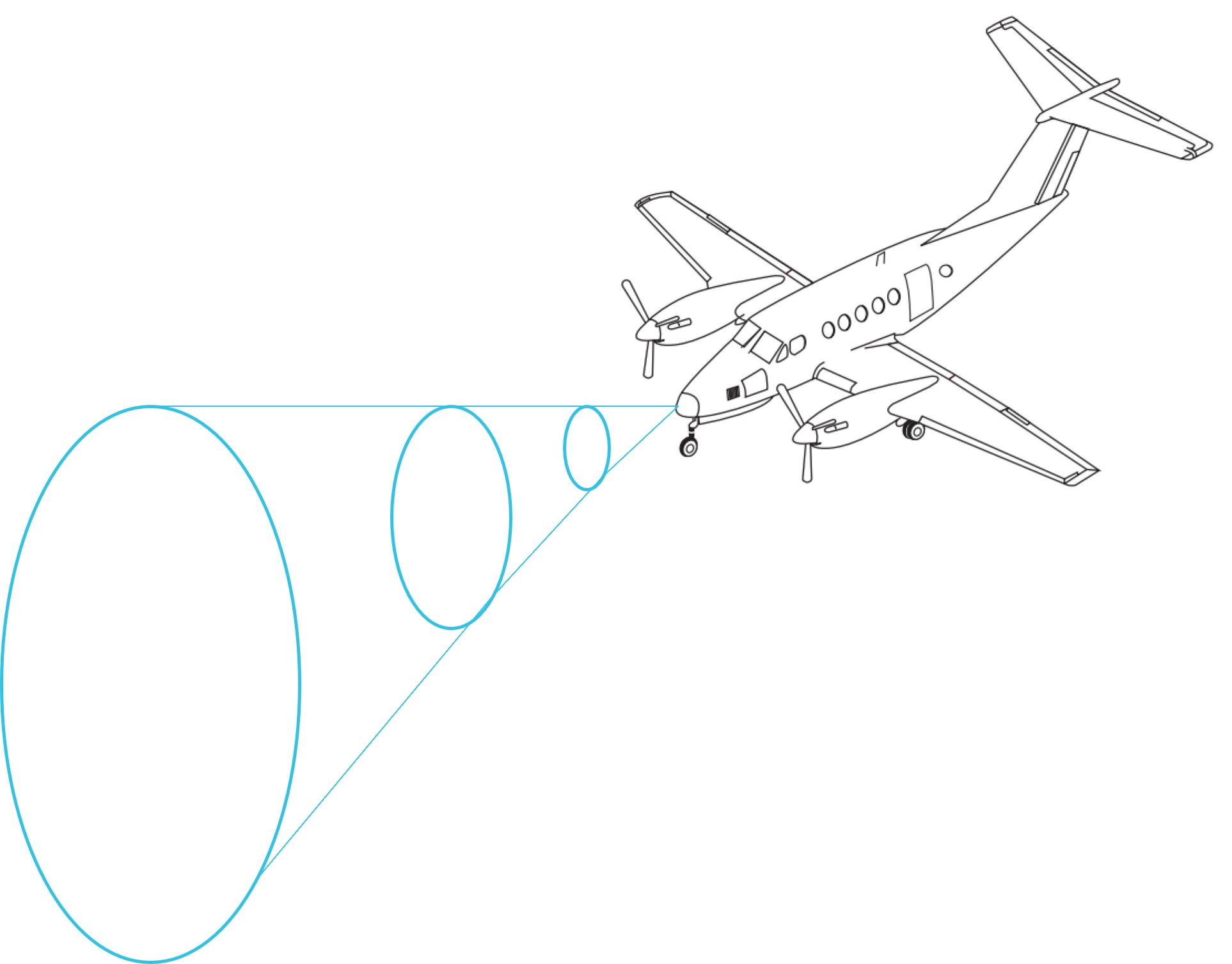
The aircraft was equipped with an airborne weather radar capable of detecting and displaying areas of precipitation along the intended flight path. The device fitted to VH-ZMW had a 12-inch antenna, allowing a maximum weather avoidance range of 320 NM (593 km).
A weather radar detects moisture by sending out a microwave pulse beam that is reflected by moisture such as precipitation, and solid objects such as terrain. The return beam is captured by the weather radar antenna and presented to the pilot. As the initial radar beam leaves the aircraft, it expands the further it is from the aircraft (Figure 3).
Figure 3: Radar beam expansion
Source: Aircraft image from FlightSafety International–Super King Air 200/B200 pilot training manual 2002
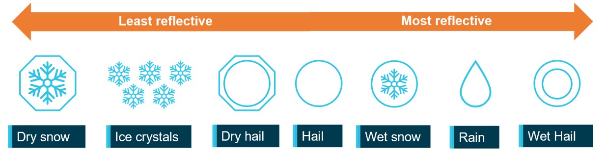
The reflectivity of precipitation is dependent on the type of precipitation, which itself is affected by the outside air temperature (Figure 4). Lower air temperatures, where the precipitation has not yet frozen, results in good reflectivity and useful information presented to the pilot. However, frozen materials are less reflective and can be misrepresented or undetected. The weather radar training course stated that the least reflective areas occur below −20°C.
Figure 4: Reflectivity of precipitation types
ATSB’s recreation of a similar image from the weather radar training video. Source: ATSB
As the temperature of precipitation within a cloud decreases with altitude, the proportion of liquid water in the atmosphere will also decrease. That will generally reduce the reflectivity within the cloud. This means that a thunderstorm does not have the same reflectivity over its altitude range with the lower/middle altitudes of the cloud having much better visibility to weather radar.
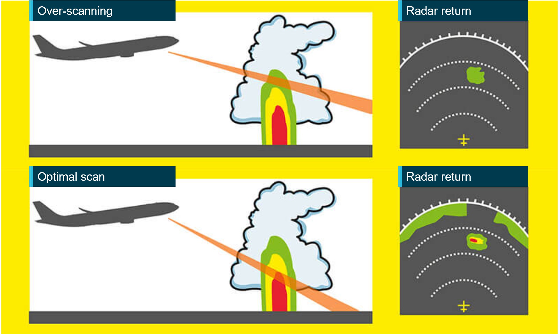
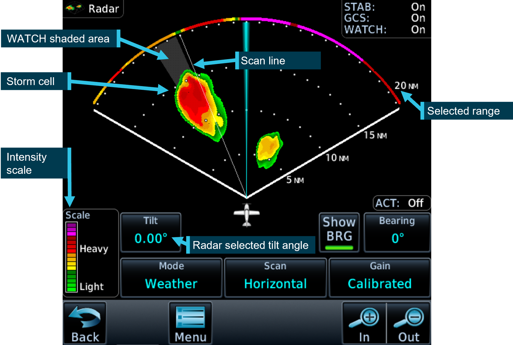
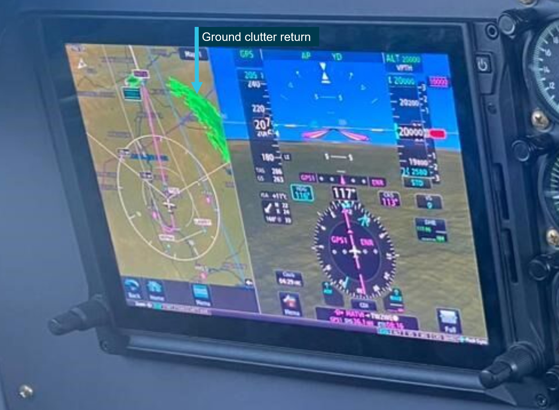
The weather radar automatically pans left and right multiple times per minute to continually refresh the information provided to the pilot. The pilot can adjust the beam position by tilting the antenna up or down, with the maximum tilt angle of 15°, both up and down. If the radar beam is tilted too low, it can return terrain which can be misinterpreted as weather, this is known as ground clutter. To reduce ground clutter, the manufacturer advised the best practise is to set the tilt angle so ground returns are visible, then slowly tilt the radar up until the ground clutter is minimised.
Over-scanning occurs when the weather radar tilt angle is set too high, providing an inaccurate radar return (Figure 5).
Figure 5: Over-scanning
Source: Optimum use of weather radar, Safety first | July 2016 - Airbus S.A.S, annotated by the ATSB
When the pilot in command was asked about their technique for determining the best tilt angle, they described a similar method. They could not recall the exact tilt setting used on the day however, stated that they believed it was set at a 1° up tilt.
If the radar detects a return, it is displayed to the pilot in different colours, dependent on the intensity of the return (Figure 6).
Figure 6: Garmin GTN 700 series weather radar
Source: Garmin GTN700 series manual, annotated by the ATSB
The weather radar has multiple options and settings to assist the pilot under different circumstances. The pilot reported that during the occurrence flight the range was set to 80–100 NM (148–185 km) and the following settings were used:
Table 1: Weather radar settings
Radar optional setting
Active (ON/OFF)
Description
Altitude compensation tilt
ON
Automatically adjusts the tilt during climb and descent to keep centre of beam at same altitude (75% of selected range). The manufacturer recommend turning this setting off once reaching desired altitude.
WATCH
(default position is ON and pilot did not recall changing this setting)
Weather attenuated colour highlight (WATCH), highlights areas that are likely associated with radar shadow.[5]
Weather messages
ON
Provides alerts when presence of heavy precipitation beyond the currently displayed range and 80 to 320 NM from aircraft present position. Messages appear when the detected weather is within 10° of current heading.
Antenna stabilisation
ON
Corrects for pitch and roll changes, it keeps radar beam relative to horizon as aircraft attitude changes.
The pilot’s guide stated the following:
The GWX weather radar should be used to avoid severe weather, not for penetrating severe weather. The decision to fly into an area of radar targets depends on target intensity, spacing between targets, aircraft capabilities, and pilot experience.
The weather radar training video stated that intense returns should be avoided by at least 20 NM (37 km).
The aircraft flight manual made the following statement regarding the use of weather radar:
Airborne weather avoidance radar is, as its name implies, for avoiding severe weather – not for penetrating it… Thunderstorms build and dissipate rapidly. Therefore, do not attempt to plan a course between echoes[6]…Remember that while hail always gives a radar echo, it may fall several miles from the nearest visible cloud and hazardous turbulence may extend to as much as 20 miles from the echo edge, avoid intense or extreme level echoes by at least 20 miles; that is, such echoes should be separated by at least 40 miles before you fly between them…
The operator’s exposition provided similar guidance to company pilots:
To minimise the risk of exceeding aircraft structural limitations due to thunderstorm turbulence,
the pilot in command should:
• ensure the aircraft does not take-off when thunderstorms are active within 10 NM of the aerodrome
• avoid thunderstorms enroute by diverting by a minimum of 10 NM upwind or 20 NM downwind
• the pilot in command must either hold or divert to an alternate aerodrome if a thunderstorm is within 20 NM of the destination aerodrome.
Forecast and reported areas of turbulence should be avoided whenever possible.
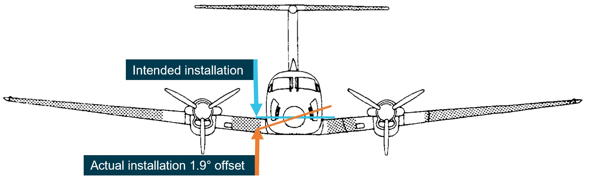
Weather radar installation
The operator advised that, as part of an aircraft upgrade, the weather radar was installed approximately 3 weeks prior to the occurrence. During the installation, it was inadvertently mounted into position offset from the lateral aircraft axis by approximately 1.9° right side low, rather than level (Figure 7).
Figure 7: Installation of the weather radar on VH-ZMW
Source: VH-ZMW flight manual, annotated by the ATSB
This meant that, with the aircraft level, when the radar panned to the maximum left position, it was tilted up 1.9° and at the maximum right position, it was tilted down 1.9°. This resulted in ground clutter appearing on the right side of the radar when the left side was clear (Figure 8).
Figure 8: Weather radar ground clutter on VH-ZMW
Source: Operator, annotated by the ATSB
Effect on the weather radar returns
Using the return from 10 NM (18.5 km) in front of the aircraft as an example, for a correct installation, the beam scanned a vertical range of approximately 8,300 ft. Therefore, if the tilt was 0° approximately 4,150 ft would be scanned below the aircraft and 4,150 ft would be scanned above the aircraft.
Based on the pilot’s recollection that the tilt angle was set at 1° up tilt, the following would be true at approximately 10 NM (18.5 km) from the aircraft’s position at FL 260:
Table 2: Minimum and maximum radar scan altitudes
Aircraft altitude = FL 260
Left scan 1.9° up from centre
Centre scan 1° above aircraft attitude
right scan right 1.9° below centre
Maximum altitude scanned
FL 330
FL 310
FL 290
Minimum altitude scanned
FL 250
FL 230
FL 210
The table shows approximate values for an aircraft at FL 260, a 12-inch antenna, the radar set at a 1° up tilt and does not consider the curvature of the earth.
Autopilot
The aircraft was equipped with an autopilot that could manipulate the aircraft in pitch, roll, and yaw. The autopilot maintained lateral and vertical navigation based on the pilot’s mode selection.
The autopilot could be disconnected by pressing the autopilot ‘AP’ button on the device or by pressing the ’AP DISC / TRIM INT’ on the control yoke. Additionally, the manufacturer’s pilot’s guide stated:
Automatic disengagement may occur due to a failure within the … system, loss of both GPS and air data inputs, strong turbulence, or exceeding the engagement attitude limits.
Anti-icing and de-icing equipment
The aircraft was capable of flying into known icing conditions and was equipped with multiple anti‑icing[7] and de-icing[8] devices. The aircraft limitations required a minimum airspeed for sustained flight in icing conditions of 140 kt.
There was a pitot tube located on each side of the aircraft nose, and they were both equipped with individually‑selectable heating elements. The heated surface prevented ice from building up and blocking the pitot tube. Additionally, the stall warning vane was equipped with a heating element.
The propeller blades were equipped with electrically‑heated de-ice boots that loosened the attachment point of any ice build-up along the propeller blade. The ice was then detached due to forces associated with the rotating propeller. In the ‘AUTO’ position all electrical heating was provided to one propeller for 90 seconds and then cycled to the other propeller for 90 seconds.
De-ice boots were located on the leading edge of the wings and horizontal stabiliser. They were pneumatically inflated by bleed air[9] from the engines. The selector switch was spring loaded to the OFF position and could be selected to either single or manual. With single selected, the distributor valve opened to inflate the wing boots for approximately 6 seconds, it then deflated the wing boots and inflated the horizontal stabiliser boots for approximately 4 seconds, this completed the cycle. With manual mode selected, all boots inflated simultaneously and remained inflated until the switch was released.
There were 2 levels of windshield heat – normal and high. When normal mode was used, heat was applied to the majority of the windshield area. When high was selected, a higher level of heat was applied to a smaller area of the windshield.
Ice vanes in the air inlet of the engine cowl were required to be extended for operations in ambient temperatures of 5°C and below, when flight free of visible moisture could not be assured. When the ice vanes were extended, it introduced a sharp turn in the engine inlet air resulting in any moisture or frozen materials continuing undeflected, due to their momentum, and being discharged overboard. This reduced the amount of moisture entering the engine. When the ice vanes were in their extended position, the aircraft’s engine performance was reduced.
The pilot reported using the available anti-icing and de-icing equipment during the flight due to the accumulation of ice, which was observed to be building rapidly.
Turbulence
The aircraft flight manual specified a turbulence penetration speed of 170 kt. The flight manual also included the following caution for turbulent air penetration:
For turbulent air penetration, use an airspeed of 170 knots. Avoid over-action on power levers. Turn off autopilot altitude hold. Keep wings level, maintain attitude and avoid use of trim. Do not chase airspeed or altitude. Penetration should be at an altitude which provides adequate manoeuvring margins when severe turbulence is encountered.
Weather
Graphical area forecast
At 1417, a graphical area forecast (GAF) was issued for the south Queensland area. It was valid between 1500 and 2300, which included the planned and actual departure time. The GAF predicted occasional[10] cumulonimbus cloud (CB) from 4,000 ft extending above 10,000 ft. It also stated that CB implied severe icing and severe turbulence.
Icing
Ice can accumulate at temperatures below 0°C in visible moisture such as cloud and rain. According to the Bureau of Meteorology, the highest risk of ice accumulation is between 0°C and −15°C. However, ice can accumulate at temperatures as low as −40°C. The Bureau of Meteorology’s–Hazardous Weather Phenomena Airframe Icing stated:
The rate of ice accumulation is directly proportional to the amount of supercooled liquid water present. In clouds, the worst-case scenario is most likely to occur in towering cumulus and cumulonimbus because of their vertical extent, the abundant supply of moisture and the large droplet size found in them.
Severity classification
The Bureau of Meteorology classified icing into different severities, depending on the rate at which it accumulated:
• Trace is used when the rate of accumulation is slightly greater than rate of sublimation (the process of ice changing directly to vapour, bypassing the liquid phase).
• Light means the rate of accumulation may create a problem if flight is prolonged in the environment (i.e more than one hour). Occasional use of de-icing/anti-icing equipment is used.
• Moderate means the rate of accumulation is such that even short encounters become potentially hazardous, and use of de-icing/anti-icing equipment or diversion is necessary.
• Severe means the rate of accumulation is such that de-icing/anti-icing equipment fails to reduce or control the hazard, and thus an immediate diversion is necessary.
The Bureau of Meteorology classified turbulence intensity into categories dependent on perceived effect on the aircraft and occupants:
• Light is associated with momentary slight erratic changes in attitude and/or altitude. Rhythmic bumpiness. Airspeed fluctuations of 5–14 kt. G–loading of 0.15 to 0.49.
• Moderate is associated with appreciable changes in attitude and/or altitude. Pilot remains in control at all times. Rapid bumps or jolts. Airspeed fluctuations of 15–24 kt. G-loading of 0.50 to 0.99.
• Severe is associated with large abrupt changes in attitude and/or altitude. Momentary loss of control. Airspeed fluctuations greater than 25 kt. G-loading of 1.00 to 1.99.
• Extreme is associated with a very difficult to control aircraft. May cause structural damage. Airspeed fluctuations of greater than 25 kt. G-loading of greater than 2.00.
SIGMET
SIGMET[11] E01 was issued at 1416 and was valid between 1416 and 1630. It identified frequent[12] thunderstorms with hail. The top of the storms was stated as FL 450 and the storms were moving east-north‑east at 15 kt. SIGMET E01 covered the area west of Toowoomba Airport and the intended flight path went through the affected area (Figure 9).
Figure 9: SIGMET area
Source: Bureau of Meteorology provided SIGMET E01, ATSB annotated and re-created the SIGMET co-ordinates on Google Earth.
The SIGMET validity period for thunderstorm activity was no longer than 4 hours or the time specified. SIGMET E01 was valid for 2 hours and 14 minutes. The Bureau of Meteorology stated that the shorter validity period was an indication that the forecast weather phenomena was expected to have ceased by the end time stated. The pilot obtained and reviewed this SIGMET, which was available prior to their departure.
A follow-up SIGMET was issued at 1641, 10 minutes after the aircraft became airborne. It also identified frequent thunderstorms with hail in the area. Air traffic control provided the new SIGMET information to the pilot at 1653 after the aircraft had already entered significant weather.
Ground‑based weather radar
The Bureau of Meteorology provided the ATSB with ground-based weather radar images at different intervals throughout the flight. The ground-based weather radar available to the pilot prior to departure, showed that, apart from the storm activity in the vicinity of Toowoomba (that the pilot delayed the departure for), moderate level precipitation could be avoided by 20 NM (37 km) along the planned departure route (Figure 10).
Figure 10: 1600 Ground‑based weather radar
The image shows the route B flight path at 1600 which was the planned departure time. It is a combination of satellite and weather radar. Source: The Bureau of Meteorology provided weather radar and satellite image, ATSB overlaid on Google Earth and annotated.
Flight data
The ATSB obtained flight data information from the aircraft’s on-board recorder, the pilot’s EFB, and third‑party ADS-B recorded information. The ATSB used this data to determine the aircraft’s position, altitude, and speed at different times throughout the flight. This data was overlaid on the weather radar information provided by the Bureau of Meteorology (Figure 11). At 1630, there was less than 20 NM between intense weather returns. However, this was after the aircraft had departed.
Figure 11: Ground - Based weather radar at 1630 and 1700
The image shows the route B flight path in blue with the actual aircraft flight path in red. It is a combination of satellite and weather radar. Source: The Bureau of Meteorology provided weather radar and satellite image, ATSB overlaid on Google Earth and annotated. Flight data provided by ADS-B exchange.
Flight planning
Flight route
The En Route Supplement Australia (ERSA) outlined the flight planning requirements for flights departing from Toowoomba Airport. It stated that when departing west, flights should plan via the MESED waypoint then to LIKTO. This was consistent with the flight plan the pilot submitted to ATC prior to departure.
The pilot later reported to the ATSB that it was normal to request the next tracking point after MESED when there was no requirement for traffic avoidance and Oakey military airspace was not active. Several recent flights completed by VH-ZMW showed that the aircraft did not initially track via the MESED waypoint.
Fuel planning
The company used fuel planning software to plan company flights. The ATSB reviewed the fuel plan calculated for this flight (Table 3).
Table 3: Fuel plan
Phase of flight
Minutes
Litres (lbs)
Climb
20
150 (264)
Cruise
184
1158 (2038)
Alternate
22
188 (331)
Trip fuel
204
1308 (2302)
Contingency fuel
20
130 (230)
Final reserve
30
164 (289)
Additional fuel
0
0
Holding
30
148 (260)
Approach
0
Taxi
51 (90)
Fuel required
307
1990 (3503)
Margin
–8
–42 (–75)
Endurance
300
1947 (3428)
As the aircraft planned to arrive at Normanton after last light, the aircraft was required to carry alternate fuel but was not required to carry both alternate and holding fuel. This was to ensure that if the aerodrome lighting could not be activated, there was sufficient fuel available to divert to a suitable airport.
The company exposition required that the flight plan include contingency fuel[13] and final reserve fuel.[14] The exposition stated that for the B200 aircraft, the final reserve fuel was 198.8 L (350 lbs). However, the software was using an incorrect lesser figure for the final reserve fuel of 164 L. As the pilot had added the extra holding fuel, the deficiency of 35 L was not an issue for this flight.
In addition, the pilot advised that they had planned to fly overhead Hughenden, and if their in-flight fuel replanning indicated that they required more fuel, they had planned that they would land and refuel.
Related occurrence
In-flight break-up involving Cessna 210N, VH-TFT, 237 km east-north-east of Katherine, Northern Territory, on 24 December 2022 (AO-2022-067).
Upon arrival overhead the Bulman region, the aircraft likely entered an area of strong convective activity from a rapidly developing thunderstorm, which probably resulted in exposure to a combination of severe turbulence and reduced visibility for the pilot.
It is probable that a combination of turbulence encountered from the thunderstorm, airspeed, and control inputs led to the excessive structural loading and in-flight separation of the right wing from the fuselage before the aircraft collided with terrain.
Safety analysis
Before departing, the pilot utilised multiple sources of information to assist with their decision‑making, resulting in them delaying their departure to avoid encountering a thunderstorm. The SIGMET received indicated that the forecast frequent thunderstorms were due to dissipate around the aircraft’s departure time. However, the graphical area forecast still showed occasional thunderstorms were forecast. The ground-based weather radar at 1600 showed that moderate precipitation could be avoided by 20 NM (37 km) along the planned route after the thunderstorm overhead Toowoomba had passed. As they taxied at 1620, the pilot was informed that there was significant build-up of cloud in the area they planned to fly through.
The route flown by the pilot took them in a direction towards that developing cloud, the effects of which were also visible on the ground-based weather radar prior to departure. During climb, the pilot remained in visual conditions until FL 260. However, once they entered cloud at FL 260, they were reliant on the weather radar, which had been installed incorrectly, to identify and avoid thunderstorms.
The incorrect installation resulted in increased ground clutter on the right side of the screen. This meant that using the recommended method for setting the tilt resulted in a higher initial baseline tilt angle. This most likely resulted in the radar beam scanning the tops of the clouds rather than the most reflective areas within a storm. This would have been exacerbated on the left side due to the increased tilt on that side.
In addition, the outside air temperature at FL 260 was −23°C, resulting in less reflective precipitation within the clouds. As it was likely that the weather radar was over-scanning and therefore, the weather radar returns presented to the pilot would not have indicated where the most active storms were. This likely resulted in the severity of the storms in the area not being visible to the pilot.
It is likely that the pilot’s in-flight assessing and planning was influenced by the airborne weather radar information, and they did not remain clear of thunderstorms by the recommended 20 NM (37 km). The ADS-B data overlaid on the ground-based radar along with the pilot’s recollection of visible lightning, turbulence, and icing are all consistent with flying into a thunderstorm.
Although the aircraft had sufficient fuel on board for the planned flight, the final reserve figure used during planning was less than the figure stipulated in the operator’s exposition. While it did not contribute to this incident, it did increase the risk of landing below the final reserve fuel.
Finally, the pilot’s pre-flight safety briefing to the passengers, which included the potential for encountering turbulence, and their decision to keep the seatbelt sign on, reduced the likelihood of passenger injuries when the aircraft encountered turbulence.
Findings
ATSB investigation report findings focus on safety factors (that is, events and conditions that increase risk). Safety factors include ‘contributing factors’ and ‘other factors that increased risk’ (that is, factors that did not meet the definition of a contributing factor for this occurrence but were still considered important to include in the report for the purpose of increasing awareness and enhancing safety). In addition ‘other findings’ may be included to provide important information about topics other than safety factors.
These findings should not be read as apportioning blame or liability to any particular organisation or individual.
From the evidence available, the following findings are made with respect to the flight into a thunderstorm involving Beech Aircraft B200, VH-ZMW, 108 km west‑north‑west of Toowoomba, Queensland on 9 October 2024.
Contributing factors
During the cruise the aircraft entered a thunderstorm, resulting in minor damage to the aircraft.
As a result of incorrect installation, the aircraft’s weather radar provided misleading information to the pilot. This reduced its effectiveness at detecting significant weather.
Other factors that increased risk
The pilot’s fuel planning, using the company software, included a final reserve that was less than the operator’s requirement.
Other findings
Prior to departure, the pilot informed the passengers of possible turbulence and kept the seatbelt sign on throughout the flight. This briefing and decision‑making likely contributed to the safety of the passengers when turbulence was experienced.
Safety actions
Whether or not the ATSB identifies safety issues in the course of an investigation, relevant organisations may proactively initiate safety action in order to reduce their safety risk. The ATSB has been advised of the following proactive safety action in response to this occurrence.
Safety action by Austrek Aviation
the operator identified and implemented an enhanced radar manufacturer training course for its pilots, specific to the installed GWX 70 radar
the incorrect antenna installation has been rectified
the flight planning software has been reviewed to ensure that the parameters are as specified in the company exposition
although fatigue was not considered to be a safety factor in the occurrence, the company has adopted the use of the Samn-Perelli Seven Point Scale fatigue reporting tool, for sign‑on and sign‑off to improve monitoring of pilot fatigue due to roster patterns.
Sources and submissions
Sources of information
The sources of information during the investigation included:
the pilot
the operator’s safety manager
Bureau of Meteorology
Garmin manuals and online weather radar training video
Under section 26 of the Transport Safety Investigation Act 2003, the ATSB may provide a draft report, on a confidential basis, to any person whom the ATSB considers appropriate. That section allows a person receiving a draft report to make submissions to the ATSB about the draft report.
A draft of this report was provided to the following directly involved parties:
the pilot
the operator
Civil Aviation Safety Authority
Textron Aviation
United States National Transportation Safety Board
A submission was received from:
the operator
The submission was reviewed and, where considered appropriate, the text of the report was amended accordingly.
Purpose of safety investigations
The objective of a safety investigation is to enhance transport safety. This is done through:
identifying safety issues and facilitating safety action to address those issues
providing information about occurrences and their associated safety factors to facilitate learning within the transport industry.
It is not a function of the ATSB to apportion blame or provide a means for determining liability. At the same time, an investigation report must include factual material of sufficient weight to support the analysis and findings. At all times the ATSB endeavours to balance the use of material that could imply adverse comment with the need to properly explain what happened, and why, in a fair and unbiased manner. The ATSB does not investigate for the purpose of taking administrative, regulatory or criminal action.
Terminology
An explanation of terminology used in ATSB investigation reports is available here. This includes terms such as occurrence, contributing factor, other factor that increased risk, and safety issue.
Publishing information
Released in accordance with section 25 of the Transport Safety Investigation Act 2003
Ownership of intellectual property rights in this publication
Unless otherwise noted, copyright (and any other intellectual property rights, if any) in this report publication is owned by the Commonwealth of Australia.
Creative Commons licence
With the exception of the Commonwealth Coat of Arms, ATSB logo, and photos and graphics in which a third party holds copyright, this report is licensed under a Creative Commons Attribution 4.0 International licence.
The CC BY 4.0 licence enables you to distribute, remix, adapt, and build upon our material in any medium or format, so long as attribution is given to the Australian Transport Safety Bureau.
Copyright in material obtained from other agencies, private individuals or organisations, belongs to those agencies, individuals or organisations. Where you wish to use their material, you will need to contact them directly.
[1]Build-ups: a general term describing convective activity and maturing clouds that are developing into thunderstorms.
[2]Waypoint: a geographical location referenced by a 5-letter identifier used for navigating.
[3]Flight Level: the aircraft altitude above sea level when the atmospheric pressure is equal to 1013 hPa. FL 240 equates to 24,000 ft.
[4]Radome: protective nose area of the aircraft which houses the airborne weather radar.
[5]Radar shadow: when the radar beam encounters precipitation, it is reflected before it can penetrate the weather fully. This leaves some areas unscanned and consequently will appear free of weather to the pilot but have the potential to be areas of heavy precipitation.
[6]Echoes: The radar returns that are displayed to the pilot.
[7]Anti-icing: devices that attempt to prevent the accumulation of ice on the aircraft.
[8]De-icing: devices that attempt to remove accumulated ice from the aircraft.
[9]Bleed air: compressed air taken from the engine to be used for other system purposes.
[10]Occasional: Well-separated features which affect, or are forecast to affect, greater than 50% but not more than 75% of an area.
[11]SIGMET: Significant Meteorological information provides a concise description concerning the occurrence or expected occurrence, in areas over which meteorological watch is being maintained, of en-route weather phenomena that are potentially hazardous to aircraft.
[12]Frequent: An area of thunderstorms with little or no separation between adjacent storms and covering more than 75% of the affected area.
[13]Turbine-engine aircraft – 5% of the flight fuel (not less than 5 minutes at holding speed at 1,500 feet above the destination aerodrome).
[14]Turbine-engine aircraft – fuel required to fly at 1,500 ft above aerodrome elevation for 30 minutes and must be remaining on completion of landing at the destination (or destination alternate).
On 1 July 2024, a Cessna 310R, registered VH-ZMB, was returning to Alice Springs from Willowra aircraft landing area, Northern Territory (NT), with only the pilot on board.
During an instrument approach in instrument meteorological conditions, the pilot reported receiving false indications from the attitude indicator and directional gyroscope. The aircraft deviated from the published approach path and tracked perpendicular to the approach track, below minimum sector altitude (MSA).
The pilot notified air traffic control at Alice Springs tower of the situation, before obtaining a clearance to track from their present position back to the initial instrument landing system approach point, for a subsequent attempt at landing.
A second approach was then flown, followed by a successful landing at Alice Springs Airport.
What the ATSB found
The ATSB found that the pilot, whilst established on the ILS approach to Alice Springs, likely experienced spatial disorientation that led to an undesired flight path, below the MSA.
In their state of distress, the pilot did not broadcast a PAN PAN call notifying air traffic control of their situation. Further, air traffic control did not issue a safety alert, which would have alerted the pilot that they were in unsafe proximity to terrain and needed to climb immediately. This was also influenced by the pilot not broadcasting a PAN PAN, but could have been made independently.
Once the pilot was outside of the required tolerances for the instrument approach and below the MSA, the pilot did not conduct a missed approach, remaining below minimum sector altitude for an extended period.
Other factors that increased the risks identified in this investigation include post‑occurrence fault finding that found the artificial horizon exhibited deviations outside the manufacturer’s required tolerances. Additionally, the pilot’s choice to not make use of the autopilot for the approach may have increased their workload and the subsequent risk of spatial disorientation during the instrument approach procedure.
What has been done as a result
The operator has since introduced an automation policy for the use of autopilot in instrument meteorological conditions and in high workload single-pilot operations.
Safety message
Pilots should not hesitate to report an urgent condition when encountering situations that may not be immediately perilous but significantly increase risk. Broadcasting a PAN PAN call when there is uncertainty about the safety status of the aircraft will alert ATC to the need for immediate assistance.
Air traffic control has a duty of care to provide safety alerts to pilots on becoming aware that an unsafe situation such as proximity to terrain has, or may, occur.
Once an aircraft is no longer on an established approach path and doubt exists as to its lateral position and location, a missed approach should be conducted, including an immediate climb to achieve a safe altitude, clear of terrain.
The investigation
Decisions regarding the scope of an investigation are based on many factors, including the level of safety benefit likely to be obtained from an investigation and the associated resources required. For this occurrence, a limited-scope investigation was conducted in order to produce a short investigation report, and allow for greater industry awareness of findings that affect safety and potential learning opportunities.
The occurrence
On the morning of 1 July 2024, a Cessna 310R, registered VH-ZMB, conducted a passenger transport flight[1] to Willowra aircraft landing area, NT, and was repositioning[2] to Alice Springs, NT, with only the pilot onboard.
At approximately 1020 local time, the pilot commenced an instrument landing system (ILS) approach[3] for runway 12 at Alice Springs Airport. This approach was manually flown (not utilising the autopilot system), in instrument meteorological conditions.[4]
At 1022:05, the aircraft was established at 4,250 ft above mean sea level (AMSL) on the approach into Alice Springs Airport on the published ILS approach profile. About 25 seconds later, the pilot recalled receiving erroneous instrument indications from the artificial horizon (AH). At 1022:30, flight data showed the aircraft departing the ILS to the left, and tracking at a perpindicular direction from the approach path with unusual aircraft bank angles (AOB) (Figure 1).
Figure 1: VH-ZMB flight path
Source: ATC recordings and recorded flight data, overlaid on Google Earth and annotated by the ATSB
At 1022:47, the pilot contacted air traffic control (ATC), using their callsign twice. The pilot reported an issue with the instruments and requested clearance to commence a second approach. The ATC controller observed, and ATC recordings indicate, a level of stress in the voice of the pilot at this time.
ATC subsequetly cleared the pilot to climb to 5,500 ft and to track directly to the initial approach fix for the ILS (position LISZT).
At 1023:36, nearly a minute after obtaining a clearance from air traffic control and over a minute from leaving the ILS profile, the pilot commenced a sustained climb.
Recorded flight data indicated that during this time, the aircraft was below the minimum sector altitude of 4,300 ft and tracking towards rising terrain. The aircraft came within its closest proximity to terrain as it passed the ridgeline at about 810 ft above ground level.
At 1024:30 the pilot acheived an altitude of 4,300 ft enroute to position for a second approach.
A subsequent ILS approach was then flown into Alice Springs, followed by a successful landing.
Table 1: Sequence of events
Time: local
Description of event
1022:05
On ILS, wings level, 4,250 ft. Standard rate of descent (ROD)
1022:30
No longer on localiser (LOC), AOB 45° left, ~3,900 ft, descending
1022:35
Tracking greater the 90° off LOC, AOB 65° left, ~3,650 ft descending
1022:43
Tracking greater than 90°of LOC, AOB 45° right, bottom of descent ~3,320 ft
1022:47
ZMB – Tower broadcast
VH-ZMB: ‘ZMB, ZMB we’ve got incorrect AH [artificial horizon] information we have lost glidepath request tracking direct to LISZT…Currently at 3,700…’
ATC: ‘Climb to 5,500 track direct to LISZT’
1023:16
Closest point of approach to the terrain was approximately 810 ft recorded
1023:36-38
Sustained climb begun with >500 fpm climb. Sustained 15° AOB left (controlled), ~3,800 ft
1024:30
10 NM minimum sector altitude (MSA) achieved 4,300 ft
Source: ATC recordings and recorded positional data tabulated by the ATSB
Context
Pilot qualifications and experience
The pilot held a commercial pilot licence (aeroplane) and a valid class 1 aviation medical certificate. The pilot reported a total flying time of 386 hours with about 66 of those being on the Cessna 310. The pilot obtained a multi-engine aeroplane instrument rating in February 2024. The pilot reported accruing 27.3 total hours of instrument flight time with 5.7 hours being accrued in the last 90 days. The pilot had been employed with the operator since April 2024 and had completed their Operator Proficiency Check – IFR [5], on 17 May 2024.
Aircraft
The Cessna 310R is a twin-engine, low-wing, 6-seat, unpressurised aircraft equipped with retractable landing gear. The aircraft was manufactured in 1976 and had greater than 16,600 hours recorded on the maintenance release. VH-ZMB was fitted with Garmin 430W avionics, coupled with a traditional avionics suite (Figure 2).
Figure 2: Photo of cockpit instruments from perspective of left (pilot) seat
Source: Operator annotated by the ATSB
The pilot reported that placement of the standby artificial horizon on the far right‑hand side of the instrument panel (Figure 2) precludes the pilot from observing angles of bank (especially to the left). However, the pilot also reported utilising the standby AH as the primary means of spatial orientation, both during the occurrence and post‑occurrence to fly the second approach and identified that recovery to a safe altitude was ultimately slowed by the significant workload of stabilising the aircraft on a limited instrument panel.
Weather conditions
Weather conditions in the Alice Springs terminal area at the time of the occurrence were identified as a moderate south-easterly wind of 10 kt, with greater than 10 km of visibility. The cloud was reported as scattered (between 3–4 oktas[6]) at 900 ft, broken (between 5–7 oktas) at 1,300 ft and overcast (8 oktas) at 2,400 ft above ground level. The pilot reported the approach was conducted in instrument meteorological conditions and recalled being in stratiform cloud [7] from 7,000 ft to 2,500 ft AMSL.
Instrument landing system approach
The Alice Springs ILS runway 12 initial approach fix is a waypoint designated as LISZT which is about 15 NM (27.8 km) from the end of runway 12. The approach descent commences at 11.5 NM (21.2 km) from the runway 12 threshold, on a standard 3° descent profile. The missed approach procedure is to track 116° magnetic and climb to 5,500 ft AMSL.
Minimum sector altitude
Minimum sector altitude (MSA) is the lowest altitude which will provide a minimum clearance of 1,000 ft above all objects located within a specified area. This specified area is contained within a circle, or a sector of a circle of 25 NM (46.3 km) or 10 NM (18.5 km) radius centred on a significant point.
In the case for Alice Springs, the significant point being used as the datum reference point is the Alice Springs VHF Omni Directional Range (VOR) station[8].
The 10 NM MSA in the area around Alice Springs Airport is 4,300 ft AMSL.
Missed approach procedures
The missed approach procedure plays a pivotal role in instrument approach safety. It provides a standardised procedure for managing an aborted approach and landing attempt, ensuring appropriate terrain clearance to safely conduct flight operations in diverse environmental conditions.
Section 15.11 of the Part 91[9] Manual of Standards contains specific circumstances where a missed approach must be conducted.
A summary of these circumstances is as follows:
during the final segment of an instrument approach, where the aircraft is not maintained within the applicable navigation tolerance for the aid in use
when the required visual reference is not established at or before reaching the missed approach point from which the missed approach procedure commences
when a landing cannot be made from a runway approach, unless a circling approach can be conducted in weather conditions equal to or better than those specified for circling
when visual reference is lost while circling to land from an instrument approach.
Procedures outlined in the Aeronautical Information Publication (AIP) state that a missed approach must be conducted under certain conditions if the aircraft is below MSA. These conditions include, but are not limited to:
• issues arising with the radio aid,
• visual reference not being established, and
• a landing cannot be effected from the runway approach.
Operational procedures require that during a missed approach manoeuvre, an immediate climb is carried out to achieve an altitude that will remove the aircraft’s exposure to the risks of collision with terrain.
Instrument approach procedures
An instrument approach or instrument approach procedure (IAP) is a series of predetermined manoeuvres for the orderly transfer of an aircraft operating under instrument flight rules from the beginning of the initial approach fix to a landing, or to a point from which a landing may be made visually.
An IAP enables a descent below the MSA, positioning the aircraft to safely approach and land.
Operations below MSA increase the risk of collision with terrain or obstacles which are an immediate threat. Maintaining the published instrument approach path assures the pilot of obstacle clearance below the MSA. Outside of these areas, while below the MSA and in instrument meteorological conditions (IMC), separation from terrain and obstacles cannot be guaranteed and the pilot must conduct a missed approach procedure.
Recorded data
Automatic dependant surveillance broadcast (ADS-B) Exchange and Flightradar24 data was collected by the ATSB and was supplemented with OzRunways data provided by the pilot.
ATSB analysis combined the ADS-B flight data and the OzRunways aircraft track data to ascertain the track position and orientation of the aircraft during the occurrence.
At 1022:30 the aircraft deviated significantly to the left of the approach path resulting in the aircraft no longer being established on the ILS approach. The aircraft was below the MSA at 3,900 ft and continued to descend to the lowest point of 3,320 ft.
About 35 seconds later the aircraft crossed a ridgeline, further reducing the vertical separation with terrain to 810 ft above ground level.
Recorded data indicated (Figure 3) that 30–40 seconds after speaking to ATC and approximately 70 seconds after leaving the ILS approach profile, the pilot commenced a sustained climb and began tracking to the initial approach fix of LISZT. During this time the aircraft was operated below the MSA.
Figure 3: Aircraft vertical profile
Source: ADS-B Exchange, Flightradar24 and OzRunways data analysed and annotated by the ATSB
Recorded data identified a significant left turn, greater than 60° AOB, with a subsequent bank to the right of greater than 40° AOB and a further left correction (Figure 4). These occurred while the aircraft was still descending. The descent was arrested, at an altitude of about 3,320 ft. With minimal climb observed for about 30 seconds before approaching rising terrain, the aircraft then passed over the ridgeline at a height of approximately 810 ft (Figure 3). (Note: Graphical figures contain smoothed data profiles that may not precisely reflect the exact data point at an exact period).
Figure 4: VH-ZMB bank angles
Source: ADS-B Exchange, Flight Radar 24 and OzRunways data analysed and annotated by ATSB
The Cessna 310R is fitted with gyroscopic instruments[10] including an artificial horizon (AH), heading indicators and turn coordinators (turn and bank).
The vacuum system instruments on the Cessna 310R consist of 2 directional gyros, 2 AH gyros and the suction gauge.
The artificial horizon is the main instrument pilots use to fly through IMC. This instrument is considered a master instrument because it presents pitch and bank attitude information directly against an artificial horizon. It is a critical instrument to allow pilots to fly through non-visual and low-visibility conditions. It indicates the aircraft's orientation relative to the earth, expressed in pitch, roll, and yaw.[11]
Figure 5: Generic example of an artificial horizon
Source: Wikipedia
The gyroscopic instruments are powered by the vacuum system, consisting of a vacuum pump on each engine, pressure relief valve for each pump, a common vacuum manifold, vacuum air filter and suction gauge. Air pressure is used to rotate vanes to spin the instrument gyroscopes thus utilising gyroscopic forces as a mechanism that keeps the instrument level with respect to the direction of gravity. The AH gyro is mounted in a double gimbal, which allows the aircraft to pitch and roll as the gyro stays vertically upright.
The pilot reported that during the approach they noticed that the suction gauge was indicating ‘low pressure’. A partial blockage or issue in the pilot suction line, immediately after the air filter, could affect the pilot (left-side) AH and the suction gauge, with nil effect on the copilot (right-side) gauges.
However, post‑occurrence maintenance inspections and ground runs could not identify any abnormalities in the vacuum system.
Figure 6: Example of the suction gauge
Source: ATSB
Post occurrence maintenance testing of the artificial horizon identified a gradual drift in pitch, up to 7°, and up to 4° drift in the roll axis over a period of 20 minutes. The AH deviations were gradual, inconsistent and outside the manufacturer’s required tolerances.
Flight automation and operator policy
Flight automation, such as an approved autopilot, utilises different control systems and technologies that reduce the requirements of human interaction.
An autopilot system can reduce the pilot’s workload. This is achieved by the automation taking over routine tasks such as maintaining altitude, heading, and airspeed. Subsequently allowing the pilot mental capacity to focus on other critical aspects of the flight, such as monitoring systems, flight path, weather conditions and communicating with air traffic control. This is particularly useful in times of a high workload environment.
The operator’s policy did not detail requirements on when it was appropriate or required to use the autopilot.
PAN PAN call
A ‘PAN PAN’ transmission is used to describe an urgent situation, but one that does not require immediate assistance. Examples of such situations include instrument malfunctions, deviation from route or entering controlled airspace without a clearance.
When an air traffic controller receives a PAN PAN call from an aircraft, the controller will declare an alert phase.[12] The Safety bulletin What happens when I declare an emergency, released by Airservices Australia, stated that ATC may provide a range of support services including:
• passing information appropriate to the situation, but not overloading the pilot
• allocating a priority status
• allocating a discrete frequency (where available) to reduce distractions
• notifying the Joint Rescue Coordination Centre (JRCC), appropriate aerodrome or other agency
• asking other aircraft in the vicinity to provide assistance.
An aircraft is in an urgency condition the moment that the pilot becomes doubtful about position, fuel endurance, weather, or any other condition that could adversely affect flight safety. The time for a pilot to request assistance is when an urgent situation may or has just occurred.
No ‘PAN PAN call was made by the pilot during the occurrence.
Air traffic control safety alert
A safety alert issued by air traffic control is instructions prefixed by the phrase 'SAFETY ALERT'. The AIP outlines a safety alert as:
ATC will issue a Safety Alert to aircraft, in all classes of airspace, when they become aware that an aircraft is in a situation that is considered to place it in an unsafe proximity to:
1. terrain;
2. obstruction;
3. active restricted areas; or
4. other aircraft.
A safety alert should trigger an appropriate response from the pilot to address and resolve the undesirable state.
When the pilot made contact with ATC, the controller reported observing a level of stress in the pilot’s voice and noticed the pilot tracking perpendicular to the approach path for the runway 12 ILS, below the MSA, towards rising terrain.
No safety alert was made by air traffic control during the occurrence.
Spatial disorientation
Spatial disorientation (SD) occurs when a pilot has a false perception of the motion or orientation of the aircraft with respect to the Earth (Ledegang & Groen, 2018), subsequently incorrectly interpreting the aircraft attitude, altitude or airspeed.
The ATSB publication Accidents involving Visual Flight Rules pilots in Instrument Meteorological Conditions (AR-2011-050) explains the basis of SD.
In order to correctly sense the orientation of the body relative to its environment, a pilot relies on a number of sensory systems in order to establish or maintain orientation: » the visual system » the vestibular system, which obtains its information from the balance organs in the inner ear » the somatic sensory system which uses the nerves in the skin and proprioceptive senses in our muscles and joints to sense gravity and other pressures on the body.
The visual system is by far the most important of the three systems, providing some 80 per cent of the raw orientation information. In conditions where visual cues are poor or absent, such as in poor weather, up to 80 per cent of the normal orientation information is missing. Humans are then forced to rely on the remaining 20 per cent, which is split equally between the vestibular system and the somatic system. Both of these senses are prone to powerful illusions and misinterpretation in the absence of visual references, which can quickly become overpowering.
Pilots can rapidly become spatially disoriented when they cannot see the horizon. The brain receives conflicting or ambiguous information from the sensory systems, resulting in a state of confusion that can rapidly lead to incorrect control inputs and resultant loss of aircraft control.
The ATSB research report, An overview of spatial disorientation as a factor in aviation accidents and incidents (B2007/0063)identified that spatial disorientation is a very common problem and estimates that the chance of a pilot experiencing SD during their career is in the order of 90 to 100%. This report also detailed several international studies showing that SD accounts for some 6 to 32% of major accidents, and some 15 to 26% of fatal accidents. The report also identified that the true prevalence of SD events is almost certainly underestimated.
The FAA Advisory Circular, Pilot’s spatial disorientation (FAA AC60-4A) discussed the challenges associated with recovering from spatial disorientation. The results of a test conducted with qualified instrument pilots found that it took as much as 35 seconds to establish full control by instruments after a loss of an applicable visual reference.
Safety analysis
This analysis will explore the factors that involved aircraft directional changes, resulting in the aircraft deviating from the published ILS approach. The deviations occurred whilst the pilot was manually flying, in instrument meteorological conditions. The consequence of this deviation led to extended flight below the minimum sector altitude with increased pilot workload prior to recovering to a safe altitude.
The pilot reported being concerned with the aircraft’s location in relation to terrain, however, believed the aircraft was under control, attributing the unusual attitudes indicated on the artificial horizon to an instrument error rather than the aircrafts attitude.
The pilot reported that, at the time, false indications by the vacuum instruments were incorrectly indicating a turn to the right, which the pilot believed to be a consequence of erroneous instrument indications. The pilot recalled that their initial response to correct this was a turn to the left and believed that the vacuum instruments were still incorrectly indicating a level of bank even though the aircraft was level.
ATSB analysis of the recorded data reviewed the aircraft pitch and bank angles, descent and climb profiles, and aircraft tracks and timings confirmed that the instrument indications (at this time) correlated with high levels of bank and the aircrafts track.
Furthermore, although the pilot remembered observing a low vacuum pressure indication, a post‑incident system inspection indicated no identified problems with vacuum pumps or the check valves.
As such, it is almost certain that there was no instrument malfunction to the extent believed by the pilot. Rather, with no visual cues due to the IMC, the pilot likely became spatially disorientated and interpreted the real instrument indications as false as they mismatched the pilot’s sensed orientation.
As is common in spatial disorientation, the pilot likely followed their sense of direction rather than the (perceived faulty) instruments, leading to directional changes of up to 90° from the approach track as well as left and right angles of bank up to 65°, whilst continuing to descend.
However, post‑occurrence maintenance fault‑finding of the artificial horizon did identify a gradual drift in pitch, (up to 7°) and roll, (up to 4°) over a period of 20 minutes. While this may have indicated a degree of unserviceability of the instrument, this was not consistent with the reported sudden and absolute failure reported by the pilot.
Prior to the deviations on approach in IMC, the pilot descended below the minimum sector altitude. However, after deviating from the approach and no longer meeting approach tolerances, the pilot did not conduct a missed approach as quickly as practicable to achieve an altitude that would remove the aircraft’s exposure to the risks of collision with terrain.
Subsequently, the pilot was below MSA and no longer offered the protection of being on the approach. This situation was further exacerbated by the aircraft being in unusual attitudes and tracking perpendicular to the approach path, without intent. If this high-risk situation had been identified either by ATC issuing a safety alert or the pilot issuing a PAN PAN call, (a PAN PAN call should have triggered a safety alert to climb), a climb could have been expedited and the risk of proximity to terrain removed sooner than was the case.
Pilots should not hesitate to report an urgent condition when encountering situations that may not be immediately perilous but significantly increase risk.
ATC recordings indicated that the pilot notified ATC that they had incorrect artificial horizon information and had lost glidepath guidance. The pilot used their callsign twice, (which can often precede a distress call), and other verbal cues were also identified by the controller to indicate the pilot was under a level of stress. Being below the MSA and off the ILS, with indications of stress, was an opportunity for the controller to issue a safety alert to the pilot to climb immediately.
In an urgent situation such as this where the safety of the aircraft was uncertain, the broadcast of a PAN PAN call would have been appropriate. Had a PAN PAN call been broadcast, ATC would have almost certainly issued a safety alert. This would have required the pilot to conduct an immediate climb, removing their subsequent risk exposure to collision with terrain.
Flight data and recordings indicated that the aircraft was below MSA, from leaving the approach profile to commencing a sustained climb to a safe altitude, for greater than one minute. Additionally, the time elapsed from notifying ATC (below MSA), to commencing a sustained climb to a safe altitude, was greater than 30 seconds. During this time, in IMC, the aircraft came within 810 ft of terrain.
Instrument flight can be considered one of the more challenging operational environments to which a pilot can be exposed. Single-pilot operations have the potential to increase pilot workload (ALPA 2019).
Manually flying a single pilot approach in IMC increases the workload of any pilot. In this occurrence, the suspected loss of a primary instrument during an instrument flight rules approach, departing the ILS approach, experiencing unusual aircraft attitudes in IMC, and subsequently conducting a second approach all increased the workload of the pilot. Use of the autopilot system has the potential to significantly reduce the workload on pilots during this approach. This is achieved by the autopilot taking over routine tasks such as maintaining altitude, heading and airspeed. Thus, allowing the pilot to focus on other critical aspects of the flight. Whilst compliant with operator procedures at the time, use of the autopilot may have reduced the risk of spatial disorientation of the pilot on approach. The pilot reported that the autopilot could not be engaged post the occurrence, when positioning for the second approach.
Use of automation can afford the pilot spare mental capacity to recognise and address navigational deviations and tolerances. Thus, aiding the pilot to respond to the operational demands of the flight in a correct and timely manner.
Findings
ATSB investigation report findings focus on safety factors (that is, events and conditions that increase risk). Safety factors include ‘contributing factors’ and ‘other factors that increased risk’ (that is, factors that did not meet the definition of a contributing factor for this occurrence but were still considered important to include in the report for the purpose of increasing awareness and enhancing safety). In addition ‘other findings’ may be included to provide important information about topics other than safety factors.
These findings should not be read as apportioning blame or liability to any particular organisation or individual.
From the evidence available, the following findings are made with respect to the flight below minimum sector altitude involving Cessna 310R, VH-ZMB, 14 km west-north-west of Alice Springs Airport, Northern Territory, on 1 July 2024.
Contributing factors
At about 8 NM from Alice Springs whilst established on the ILS approach in instrument meteorological conditions, the pilot likely experienced spatial disorientation that led to directional changes of up to 90° from the approach track as well as left and right angles of bank up to 65°, whilst continuing to descend.
The pilot did not maintain track or glidepath and deviated from instrument landing system below the minimum sector altitude. Once outside of the required tolerances, the pilot did not conduct a missed approach, which increased the risk of collision with terrain.
Air traffic control did not issue a safety alert. This would have alerted the pilot that they were in unsafe proximity to terrain and needed to climb immediately.
The pilot did not broadcast a PAN PAN call notifying air traffic control and other traffic of their situation, leading to the pilot remaining below minimum sector altitude for an extended period without air traffic control instruction to climb.
Other factors that increased risk
Post occurrence fault‑finding of the artificial horizon, identified gradual and inconsistent deviations outside the manufacturer’s required tolerances.
The pilot did not utilise the autopilot for the approach even though they were in a high workload environment. The appropriate use of autopilot can reduce workload and subsequent risk of spatial disorientation such as during an instrument approach.
Safety actions
Safety action by Avcharter
The operator has since introduced an automation policy for the use of autopilot in conditions applicable to instrument meteorological conditions (IMC) and in high workload single-pilot environments.
Sources and submissions
Sources of information
The sources of information during the investigation included:
the pilot of the flight
the head of flight operations for the operator
Civil Aviation Safety Authority
the aircraft manufacturer
the maintenance organisation for VH-ZMB
independent avionics specialists
Airservices Australia
recorded data from the GPS unit on the aircraft.
References
Airservices Australia. (2024) Aeronautical Information Publication Australia.
Airline Pilots Association International (ALPA) (2019) The dangers of single pilot operations Retrieved from
Bailey, R. E., Kramer, L. J., Kennedy, K. D., Stephens, C. L., & Etherington, T. J. (2017, September). An assessment of reduced crew and single pilot operations in commercial transport aircraft operations. InN2017 IEEE/AIAA 36th Digital Avionics Systems Conference (DASC) (pp. 1‑15). IEEE.
Barnum, F., & Bonner, R. (1971). Epidemiology of USAF spatial disorientation aircraft accidents, 1 Jan 1958-31 Dec 1968. Aerospace Med, 42, 896-898.
Braithwaite, M., Durnford, S., & Crowley, J. (1998b). Spatial disorientation in US Army rotary-wing operations. Aviation Space Environ Med, 69, 1031-1037.
Cessna 1976, Pilot’s Operating Handbook, Cessna 310 Skyhawk, model C310R
Cheung, B., Money, K., Wright, H., & Bateman, W. (1995). Spatial disorientation implicated accidents in the Canadian forces, 1982-92. Aviation Space Environ Med, 66, 579-585.
Civil Aviation Safety Authority. (2020) Part 91 (General Operating and Flight Rules) Manual of Standards.
Federal Aviation Authority. (1983). Advisory Circular AC60-4A: Pilot’s spatial disorientation
Gillingham, K., & Previc, F. (1996). Spatial orientation in flight. In R. DeHart (Ed.), Fundamentals of aerospace medicine (2nd ed., pp. 309-397.). Baltimore: Williams & Wilkins
Hixson, W., Niven, J., & Spezia, E. (1972). Major orientation error accidents in regular Army UH-1 aircraft during FY 1969. Accident factors report namrl1169. Pensacola, FL: Naval Aerospace Medical Research Laboratory.
Knapp, C., & Johnson, R. (1996). F-16 class a mishaps in the U.S. Air Force, 1975- 93. Aviat Space Environ Med, 67, 777-783
Ledegang, W. D., & Groen, E. L. (2018). Spatial disorientation influences on pilots’ visual scanning and flight performance. Aerospace medicine and human performance, 89(10), 873-882.
Lyons, T., Ercoline, W., O’Toole, K., & Grayson, K. (2006). Aircraft and related factors in crashes involving spatial disorientation: 15 years of U.S. Air Force data. Aviat Space Environ Med, 77, 720-723.
Moser, R., Jr. (1969). Spatial disorientation as a factor in accidents in an operational command. Aerospace Med, 40, 174-176.
Singh, B., & Navathe, P. (1994). Indian Air Force and world spatial disorientation accidents: A comparison. Aviation Space Environ Med, 65, 254-256.
Submissions
Under section 26 of the Transport Safety Investigation Act 2003, the ATSB may provide a draft report, on a confidential basis, to any person whom the ATSB considers appropriate. That section allows a peon receiving a draft report to make submissions to the ATSB about the draft report.
A draft of this report was provided to the following directly involved parties:
The pilot of the flight
The operator
Air traffic controller
Airservices Australia
Civil Aviation Safety Authority
Purpose of safety investigations
The objective of a safety investigation is to enhance transport safety. This is done through:
identifying safety issues and facilitating safety action to address those issues
providing information about occurrences and their associated safety factors to facilitate learning within the transport industry.
It is not a function of the ATSB to apportion blame or provide a means for determining liability. At the same time, an investigation report must include factual material of sufficient weight to support the analysis and findings. At all times the ATSB endeavours to balance the use of material that could imply adverse comment with the need to properly explain what happened, and why, in a fair and unbiased manner. The ATSB does not investigate for the purpose of taking administrative, regulatory or criminal action.
Terminology
An explanation of terminology used in ATSB investigation reports is available here. This includes terms such as occurrence, contributing factor, other factor that increased risk, and safety issue.
Publishing information
Released in accordance with section 25 of the Transport Safety Investigation Act 2003
Ownership of intellectual property rights in this publication
Unless otherwise noted, copyright (and any other intellectual property rights, if any) in this report publication is owned by the Commonwealth of Australia.
Creative Commons licence
With the exception of the Commonwealth Coat of Arms, ATSB logo, and photos and graphics in which a third party holds copyright, this report is licensed under a Creative Commons Attribution 4.0 International licence.
The CC BY 4.0 licence enables you to distribute, remix, adapt, and build upon our material in any medium or format, so long as attribution is given to the Australian Transport Safety Bureau.
Copyright in material obtained from other agencies, private individuals or organisations, belongs to those agencies, individuals or organisations. Where you wish to use their material, you will need to contact them directly.
[1]Flight operated under Part 135 of the Civil Aviation Safety Regulations. Part 135 of the Civil Aviation Safety Regulations (CASR) covers the air transport rules for smaller aeroplanes.
[2]Flight was operated under Part 91 of Civil Aviation Safety Regulations. Part 91 of the Civil Aviation Safety Regulations (CASR) – General operating and flight rules, sets out the general operating rules for all pilots and operators. It consolidates all of the general operating and flight rules for Australian aircraft.
[3] Instrument Landing System (ILS) approach is defined as a precision runway approach aid based on two radio beams which together provide pilots with both vertical and horizontal guidance during an approach to land.
[4]Instrument meteorological conditions (IMC) means meteorological conditions other thanvisual meteorological conditions.
[5] Instrument proficiency check means an assessment, against the standards mentioned in the Part 61 Manual of Standards, of a pilot’s competency to pilot an aircraft under the IFR
[6] Total cloud amount measured visually by the fraction (in eighths or oktas) of the sky covered by clouds.
[7] Stratus clouds tend to be featureless, low altitude clouds that cover the sky in a blanket of white or grey.
[8] VHF Omni Directional Range (VOR) navigation consists of a ground-based component, called VOR stations, (as well as receivers installed in the aircraft). VOR stations are infrastructure, often located at terminal areas, to aid in navigation and approaches.
[9] Part 91 of Civil Aviation Safety Regulations, General operating and flight rules.
[10]Gyroscopic flight instruments are instruments which have a mechanical gyroscope incorporated into their design.
[11]Rotation around the front-to-back axis is called roll. Rotation around the side-to-side axis is called pitch. Rotation around the vertical axis is called yaw.
[12]Alert phase: a situation where apprehension exists as to the safety of an aircraft and its occupants (this generally equates to a PAN PAN).
On 25 January 2024, at 0640 local time, a Raytheon Aircraft Company C90A aircraft, registered VH-JEO and operated by Goldfields Air Services, departed Kalgoorlie-Boulder Airport (Kalgoorlie), Western Australia (WA) on a commercial passenger transport flight to Warburton Airport, WA with one pilot and 2 passengers on board.
About half an hour into the flight, while operating in instrument meteorological conditions, an avionics failure resulted in the aircraft commencing an uncommanded turn to the right. In response, the pilot disengaged the autopilot and repositioned the aircraft back onto the correct heading. During this manoeuvring, altitude variations between −400 ft and +900 ft were recorded on ADS‑B tracking services.
Having observed the aircraft deviate laterally and vertically, the monitoring air traffic controller queried the pilot’s intentions several times. The combination of manually flying in IMC, troubleshooting and the interactions from ATC resulted in a high workload situation for the pilot.
The pilot elected to return to Kalgoorlie and the aircraft landed around 0800 local time.
What the ATSB found
The ATSB identified that the remote gyroscope failed, resulting in erroneous indications on the horizontal situation indicator while the aircraft was being operated with the autopilot engaged in heading mode. This resulted in a sustained, uncommanded right turn.
Contrary to the guidance in the pilot operating handbook, the pilot did not deselect the autopilot and continued to operate the autopilot in heading mode, which led to them experiencing high workload and sustained control issues.
Finally, although probably influenced by their focused attention on the malfunction, the pilot did not make a PAN PAN broadcast to ATC, reducing the opportunity for the controller to provide appropriate assistance.
What has been done as a result
Since the incident, the operator has:
issued a notice to aircrew reminding pilots to disengage the autopilot and hand fly the aircraft any time there are failure modes indicated on the autopilot annunciator
added training exercises relating to horizontal situation indicator and artificial horizon instrument failures in the line-oriented flight training phase of all pilots’ training.
Safety message
This incident highlights the value of aircraft system knowledge and pilot operating handbook familiarity in resolving malfunctions. Additionally, pilots should utilise all options to reduce their workload, including requesting assistance from air traffic services (ATS) when they recognise an emergency situation developing, to allow the appropriate support measures to be activated.
Controllers are reminded that a pilot in difficulty may not immediately alert ATS if they are disoriented or focused on maintaining aircraft control. If a controller assesses they may be able to assist, this should be communicated proactively.
The investigation
Decisions regarding the scope of an investigation are based on many factors, including the level of safety benefit likely to be obtained from an investigation and the associated resources required. For this occurrence, a limited-scope investigation was conducted in order to produce a short investigation report, and allow for greater industry awareness of findings that affect safety and potential learning opportunities.
The occurrence
At 0640 local time on 25 January 2024, a Raytheon Aircraft Company C90A aircraft, registered VH-JEO and operated by Goldfields Air Services, departed Kalgoorlie-Boulder Airport (Kalgoorlie), Western Australia (WA) on a commercial passenger transport flight to Warburton Airport, WA (Figure 1). On board were the pilot and 2 passengers.
Figure 1: Flight track from Kalgoorlie to Warburton
Source: Google Earth overlaid with Flight Radar 24 data, annotated by ATSB
Around half an hour after departure, while maintaining flight level (FL) 210[1] and tracking to waypoint[2] KAPSU in instrument meteorological conditions (IMC)[3] with the autopilot engaged (altitude hold and navigation mode), the pilot requested and received a clearance from air traffic control (ATC) to divert left of track due to a storm ahead. The pilot changed the mode in the autopilot from navigation (tracking to waypoint KAPSU) to heading. They then set an initial target heading of around 350° using the heading bug[4] on the horizontal situation indicator (HSI)[5] (Figure 2), to track left of the storm before flying parallel to the original track to KAPSU. Once past the storm, the pilot changed the heading to around 030°, to re‑intercept the original track (Figure 3).
Figure 2: Horizontal situation indicator
Photo taken by the pilot during the flight showing the heading flag, the heading bug and the instrument indicating the aircraft heading was 027˚. Source: The pilot, annotated by the ATSB
The aircraft commenced the right turn, but it continued to turn through the selected heading. In response, the pilot moved the heading bug left, but observed that the aircraft was very slow to respond.
Still in IMC and now heading towards the storm and associated severe turbulence that the pilot had diverted to avoid, the pilot completely disconnected the autopilot, and manually manoeuvred the aircraft away from the storm and towards the planned track. During the turn, uncommanded altitude variations between −400 ft and +900 ft were recorded on ADS‑B tracking services.
Figure 3: VH-JEO flight path
Source: Google Earth overlaid with Flight Radar 24 data, annotated by the ATSB
The controller observed the aircraft deviating from the cleared track and questioned the pilot as to their intentions. The pilot responded that they were ‘having some issues with the avionics’. The controller subsequently observed the aircraft descending and asked the pilot if they ‘were descending as well?’. The pilot then requested a block level from FL 210 to FL 100, which the controller advised they were unable to accommodate, due to class E airspace[6] below. The controller instead issued a descent clearance to FL 190, which the pilot acknowledged.
About a minute later the controller observed the aircraft climbing and asked the pilot ‘are you climbing?’ to which the pilot responded, ‘stand by’. Due to the presence of other aircraft, the controller advised that they needed the aircraft to maintain a level and asked the pilot what level they required. The pilot then advised they were descending back to FL 190. A minute later, the controller asked if the pilot would like vectors back to Kalgoorlie, which the pilot replied they were ‘having trouble with the autopilot in IMC’ and to ‘stand by’.
Once the aircraft returned to the planned track, the pilot re-engaged the autopilot and armed the navigation and altitude select mode. The navigation mode normally activated when the aircraft was within 90° of the planned track, but on this occasion it failed to engage and the aircraft recommenced an uncommanded turn to the right.
The pilot then detected that the HDG (heading) red flag was displayed on the HSI, indicating that the magnetic input to the HSI had failed or was unreliable. At this time, the flight director (FD) indicator bars disappeared from the electronic attitude direction indicator (ADI), and a red FD flag was also displayed, indicating that the flight director was no longer reliable.
At 0721, the controller asked if the pilot was intending to hold at their current location. The pilot advised that they were trying to resolve the issues, with a preference to continue to Warburton. Around 3 minutes later, unsure of the cause of the instrumentation issue, the pilot requested a return to Kalgoorlie, which was approved.
The pilot kept the autopilot engaged in heading mode and altitude select, with the intention of reducing their workload while operating in turbulence and IMC. By making continual inputs to the heading bug, the aircraft completed a turn onto the reciprocal track. The pilot assessed that the course deviation indicator on the HSI appeared to be working throughout the reciprocal turn to Kalgoorlie, as it still provided guidance to KAPSU. The pilot then selected the Kalgoorlie VOR[7] to provide directional reference on the left HSI and also monitored the right side HSI and the independent Garmin 600 GPS during the return flight. The aircraft’s system did not permit the right side HSI or Garmin 600 to be coupled to the autopilot (see the section titled Heading failure).
The aircraft landed at Kalgoorlie at 0802. A post-flight engineering inspection found that the left remote gyroscope had failed resulting in the left HSI providing erroneous indications.
Context
Pilot qualifications and experience
The pilot held a commercial pilot licence (aeroplane) with a Class 1 aviation medical certificate and had accrued 1,153 hours of aeronautical experience, 144 of which were on the C90A aircraft type. In May 2023, the pilot completed line-oriented flight training with the aircraft operator, which included knowledge and use of the autopilot.
Aircraft
VH-JEO was a Raytheon Aircraft C90A, twin‑engine turboprop aircraft with Pratt & Whitney PT6A‑21 engines. The aircraft was manufactured in the United States in 1997 and issued serial number LJ-1464. The aircraft was first registered in Australia in 2013. There were no outstanding maintenance items at the time of the incident.
Weather conditions
Data obtained from the Bureau of Meteorology showed that, at the time and location of the occurrence, icing and thunderstorms were forecast and present, with associated severe turbulence. The pilot reported that only light icing was present during the incident, which was appropriately managed by the aircraft’s anti‑icing systems and not considered a factor in the incident.
Heading failure
The C90A pilot operating handbook stated that, in the event of a heading failure on the HSI (indicated by a red HDG flag on the instrument), the pilot was to reference the instrument displaying compass no 2 data – either the opposite HSI or the same side RMI (Figure 4).
The C90A Collins autopilot fitted to the aircraft was unable to be coupled to the copilot’s (right) side instruments.
Figure 4: Compass systems on C90A
Source: King Air C90A/B Pilot training manual
Manufacturer guidance for flight director flag
The Collins FCS-65 autopilot guide stated that a flight director (FD) flag was generated when a system fault, such as a heading failure, warranted disengaging the autopilot. However, by the time the pilot identified the FD flag during this occurrence, they had already disengaged and re‑engaged the autopilot.
Collins Aerospace advised that several inputs to the autopilot computer monitor could activate the red FD flag on the ADI. Therefore, before continuing to use the ADI, if the red FD flag was in view there was a requirement to conduct an airborne self-test to determine the specific cause. The manufacturer further noted that this test is not widely practiced by pilots and was not included in the POH. As such, pilots were unlikely to be able to conduct the self‑test in flight and the POH recommended simply disengaging the autopilot if the red flag was present.
The United States National Transportation Safety Board (NTSB) further advised that both the aircraft manufacturer and the autopilot manufacturer suggested that in the event of any autopilot malfunction (whether due to a failure of the autopilot or a system that feeds the autopilot) the autopilot should not be re-engaged. While there may be some input failure modes that would still allow modes of the autopilot to be useful, this would require the pilots to troubleshoot in flight, which they did not advise.
PAN PAN call
A ‘PAN PAN’ transmission is used to describe an urgent situation but one that does not require immediate assistance. Examples of such situations include instrument malfunctions and deviation from route or track in controlled airspace without a clearance.
According to the Manual of Air Traffic Services, when an air traffic controller receives a PAN PAN call from an aircraft, the controller will declare an alert phase.[8] Safety bulletin What happens when I declare an emergency, released by Airservices Australia, states that ATC may provide a range of support services including:
passing information appropriate to the situation, but not overloading the pilot
allocating a priority status
allocating a discrete frequency (where available) to reduce distractions
notifying the Joint Rescue Coordination Centre (JRCC), appropriate aerodrome or other agency
asking other aircraft in the vicinity to provide assistance.
Safety analysis
In-flight failure of the left remote gyroscope induced a slow, steady erroneous roll of the primary HSI display. As the autopilot was at the time operating in heading mode, the aircraft also began a constant turn to the right, attempting to follow the drifting heading bug.
In response to the observed aircraft turn, the pilot fully disengaged the autopilot (consistent with the guidance in the pilot operating handbook (POH) for an FD flag warning on the ADI) and manually manipulated the aircraft back onto the desired heading. During that manoeuvring, likely due to a combination of turbulence and manually flying in IMC, the aircraft experienced unintended altitude variations and the pilot was subjected to high workload.
While the pilot recognised the HSI was giving spurious readings, contrary to the guidance in the aircraft’s POH, they re‑engaged the autopilot (including heading mode) in an attempt to reduce their workload. Unfortunately, this had the opposite effect as the aircraft recommenced the uncommanded right turn, which the pilot countered by making constant adjustments to the heading bug.
In this instance, disengaging the autopilot and monitoring an alternate (secondary) compass system navigation aid (left RMI or right HSI) would have eliminated the uncommanded turn and enabled accurate instrument navigation.
The pilot reported that the interactions with ATC during this incident further increased workload and stress, but the pilot did not declare a PAN PAN to alert the controller to the extent of the instrument issues. While that omission was probably due to the pilot’s focused attention on the malfunction, it reduced the opportunity for the controller to provide appropriate assistance.
Findings
ATSB investigation report findings focus on safety factors (that is, events and conditions that increase risk). Safety factors include ‘contributing factors’ and ‘other factors that increased risk’ (that is, factors that did not meet the definition of a contributing factor for this occurrence but were still considered important to include in the report for the purpose of increasing awareness and enhancing safety). In addition ‘other findings’ may be included to provide important information about topics other than safety factors.
These findings should not be read as apportioning blame or liability to any particular organisation or individual.
From the evidence available, the following findings are made with respect to the instrument failure andcontrol issues involving Raytheon Aircraft Company C90A, VH-JEO, 170 km north-east of Kalgoorlie-Boulder Airport, Western Australia on 25 January 2024.
Contributing factors
The left remote gyroscope failed resulting in erroneous readings on the horizontal situation indicator while the aircraft was being operated with the autopilot engaged in heading mode, resulting in an uncommanded right turn.
The pilot continued to use the autopilot in heading mode, contrary to the guidance in the pilot operating handbook, which led to them experiencing a higher workload and sustained control issues.
Other factors that increased risk
The pilot did not make a PAN PAN broadcast to ATC, reducing the opportunity for the controller to provide appropriate assistance.
Safety actions
Whether or not the ATSB identifies safety issues in the course of an investigation, relevant organisations may proactively initiate safety action in order to reduce their safety risk. All of the directly involved parties are invited to provide submissions to this draft report. As part of that process, each organisation is asked to communicate what safety actions, if any, they have carried out to reduce the risk associated with this type of occurrences in the future. The ATSB has so far been advised of the following proactive safety action in response to this occurrence.
Safety action by Goldfields Air Services
The aircraft operator:
Since the incident, the operator has:
issued a notice to aircrew reminding pilots to disengage the autopilot and hand fly the aircraft any time there are failure modes indicated on the autopilot annunciator
added training exercises relating to horizontal situation indicator and artificial horizon instrument failures in the line-oriented flight training phase of all pilots’ training.
Sources and submissions
Sources of information
The sources of information during the investigation included the:
incident pilot
air traffic control audio tapes
chief engineer and head of flight operations of Goldfields Air
recorded ADS-B data
Bureau of Meteorology
References
King Air C90A/B pilot training manual, volume 2 aircraft systems, chapter 16, Flight safety international, 2002. P. 333
Manual of Air Traffic Services, version 67.1, 21 March 2024, Airservices Australia and Department of Defence, p.160
Collins FCS-65 Flight Control System (3rd edition) – pilot’s guide, Collins general aviation division/Rockwell international corporation, October 1989, p.26-27.
Raytheon Aircraft Beech King Air C90A Pilot’s Operating Handbook and FAA approved airplane flight manual supplement for the Collins FCS-65H automatic flight control system with Collins EFIS 84 electronic flight instrument system (EFIS), Raytheon aircraft company, 2002, p. 6.
Submissions
Under section 26 of the Transport Safety Investigation Act 2003, the ATSB may provide a draft report, on a confidential basis, to any person whom the ATSB considers appropriate. That section allows a person receiving a draft report to make submissions to the ATSB about the draft report.
A draft of this report was provided to the following directly involved parties:
Airservices Australia
incident pilot
Goldfields Air Services
Civil Aviation Safety Authority
Aircraft manufacturer
Autopilot manufacturer
National Transportation Safety Board.
Submissions were received from:
Airservices Australia
Goldfields Air Services
Aircraft manufacturer
Autopilot manufacturer
National Transportation Safety Board.
The submissions were reviewed and, where considered appropriate, the text of the report was amended accordingly.
Purpose of safety investigations
The objective of a safety investigation is to enhance transport safety. This is done through:
identifying safety issues and facilitating safety action to address those issues
providing information about occurrences and their associated safety factors to facilitate learning within the transport industry.
It is not a function of the ATSB to apportion blame or provide a means for determining liability. At the same time, an investigation report must include factual material of sufficient weight to support the analysis and findings. At all times the ATSB endeavours to balance the use of material that could imply adverse comment with the need to properly explain what happened, and why, in a fair and unbiased manner. The ATSB does not investigate for the purpose of taking administrative, regulatory or criminal action.
Terminology
An explanation of terminology used in ATSB investigation reports is available here. This includes terms such as occurrence, contributing factor, other factor that increased risk, and safety issue.
Publishing information
Released in accordance with section 25 of the Transport Safety Investigation Act 2003
Ownership of intellectual property rights in this publication
Unless otherwise noted, copyright (and any other intellectual property rights, if any) in this report publication is owned by the Commonwealth of Australia.
Creative Commons licence
With the exception of the Coat of Arms, ATSB logo, and photos and graphics in which a third party holds copyright, this publication is licensed under a Creative Commons Attribution 3.0 Australia licence.
Creative Commons Attribution 3.0 Australia Licence is a standard form licence agreement that allows you to copy, distribute, transmit and adapt this publication provided that you attribute the work.
The ATSB’s preference is that you attribute this publication (and any material sourced from it) using the following wording: Source: Australian Transport Safety Bureau
Copyright in material obtained from other agencies, private individuals or organisations, belongs to those agencies, individuals or organisations. Where you wish to use their material, you will need to contact them directly.
[1]Flight level: at altitudes above 10,000 ft in Australia, an aircraft’s height above mean sea level is referred to as a flight level (FL). FL 210 equates to 21,000 ft.
[2]Waypoint: a specified geographical location used to define an area navigation route or the flight path of an aircraft employing area navigation.
[3]Instrument meteorological conditions (IMC): weather conditions that require pilots to fly primarily by reference to instruments, and therefore under instrument flight rules (IFR), rather than by outside visual reference. Typically, this means flying in cloud or limited visibility.
[4]Heading bug: a marker on the heading indicator that can be rotated to a specific heading for reference purposes, or to command an autopilot to fly that heading.
[5]Horizontal situation indicator (HSI): an instrument that combines magnetic heading indication and navigation guidance.
[6]Class E airspace: mid-level en route controlled airspace is open to both IFR and VFR aircraft. IFR flights are required to communicate with ATC and must request ATC clearance.
[7]Very high frequency omnidirectional range station (VOR): transmitters that support non-precision (lateral guidance only) approach and en route navigation.
[8]Alert phase: a situation where apprehension exists as to the safety of an aircraft and its occupants (this generally equates to a PAN PAN).
Occurrence summary
Investigation number
AO-2024-003
Occurrence date
25/01/2024
Location
170 km north-east of Kalgoorlie-Boulder Airport
State
Western Australia
Report release date
17/09/2024
Report status
Final
Investigation level
Short
Investigation type
Occurrence Investigation
Investigation status
Completed
Mode of transport
Aviation
Aviation occurrence category
Avionics/flight instruments
Occurrence class
Incident
Highest injury level
None
Aircraft details
Manufacturer
Raytheon Aircraft Company
Model
C90A
Registration
VH-JEO
Serial number
LJ-1464
Aircraft operator
Goldfields Air Services
Sector
Turboprop
Operation type
Part 135 Air transport operations - smaller aeroplanes
On 6 October 2023, at about 2200 local time, the pilot of a Lancair IV-PT departed Parafield Airport, on a private flight under the instrument flight rules,[1] to Whyalla, South Australia.
The pilot had been awake for 16 hours when they arrived at the airport to collect the aircraft from a maintenance organisation, who had performed maintenance on the aircraft to rectify a hydraulic leak.
The pilot reported they conducted a thorough pre-flight inspection and completed ground runs prior to departure.
During the take-off run, the pilot detected abnormal airspeed fluctuations and rejected the take-off. The pilot backtracked and commenced a second take-off. The pilot noted that the airspeed indications appeared normal, and rotated when the aircraft reached 85 kt.
During initial climb, the pilot observed the airspeed indicator was stuck between 80–90 kt and the altimeter was fluctuating between 300–800 ft. The pilot ensured that they maintained terrain clearance by tracking the assigned standard instrument departure (SID), confirming the engine was set to a known power setting and maintaining a steady attitude.
The pilot contacted the Adelaide approach controller and advised that they had unreliable airspeed and altitude indications and initially requested an immediate return to Parafield. However, recognising the importance of maintaining a higher airspeed to prevent a stall, changed the request to divert to Adelaide Airport which had a longer, wider runway. The pilot was also mindful that there were no emergency services at Parafield, whereas these services would be available at Adelaide, to assist in the event of an accident.
As requested by the pilot, the approach controller provided the pilot with the aircraft’s transponder altitude and the aircraft’s groundspeed,[2] calculated from the secondary radar. However, with no information regarding wind speed or direction, the pilot was unable to determine their indicated airspeed.[3]
As the aircraft approached the Adelaide Hills, the pilot was cognisant that the lowest safe altitude (LSALT)[4] was 3,800 ft in this area. At this point, the pilot recalled having a handheld GPS unit that was independent of the aircraft’s static system, and it indicated that the aircraft was maintaining 4,000 ft. However, when the controller queried if the pilot could see the terrain, the pilot replied that they could not, resulting in the controller offering a coastal visual approach.
The pilot had concerns flying over the ocean as at night they would have no visual cues over the water; however, the controller suggested the city lights could be used as a reference point and another aircraft in the vicinity advised that conditions along the coast were clear. A further aircraft also relayed that the wind conditions were calm, which would aid the pilot in determining an approximate indicated airspeed.
The pilot further considered that they were flying over an urban area and in the event of an accident this may present dangers to people below. Consequently, they elected to fly the coastal approach for runway 12 at Adelaide Airport.
A short time later, the pilot could see Adelaide Airport and recognised they were too high for the approach, which was confirmed by the controller. The pilot conducted an orbit to descend and configured the aircraft for landing.
The pilot established the aircraft on the PAPI,[5] and kept the aircraft’s power higher than normal to maintain a faster airspeed to minimise the risk of a stall. This resulted in a prolonged flare and touching down about one third along runway 12. Emergency services were in attendance but were not required.
Post-flight, the aircraft’s pitot static tubing was found to be cracked, and black debris was also found throughout the system. It was unable to be determined if this was a result of the previous maintenance or an isolated fault.
Safety action
The pilot advised that following this incident, they have added a data field on the aircraft’s Garmin screen that contains the handheld GPS altitude.
Safety message
There are several key safety messages that arise from this occurrence.
If you find a maintenance discrepancy and find yourself saying that it is ‘probably’ okay to fly anyway, you need to revisit the consequences (FAA, 2023). The safest thing to do is have the issue corrected prior to taking off.
However, if you do encounter unreliable airspeed indications during the flight, the immediate response is to maintain control with a known power setting and pitch attitude producing known performance, even if indications of that performance are uncertain (CASA, 2022). There have been a number of reported occurrences where potentially severe consequences were avoided by a pilot’s decision to seek assistance from air traffic control or nearby flight crew.
Fatigue makes a pilot less vigilant and more willing to accept a lesser performance level than normal, and they will often begin to show signs of poor judgement (CASA, 1999). Pilots must manage fatigue risk including not operating an aircraft if they feel that they are unfit due to fatigue or likely to become so (CASA, 2023).
Acknowledgement
The ATSB acknowledges the valuable assistance provided during this occurrence by the Adelaide approach controller, and other aircraft in the vicinity, who relayed information and acted as a calming influence for the incident pilot.
About this report
Decisions regarding whether to conduct an investigation, and the scope of an investigation, are based on many factors, including the level of safety benefit likely to be obtained from an investigation. For this occurrence, no investigation has been conducted and the ATSB did not verify the accuracy of the information. A brief description has been written using information supplied in the notification and any follow-up information in order to produce a short summary report and allow for greater industry awareness of potential safety issues and possible safety actions.
[1] Instrument flight rules (IFR): a set of regulations that permit the pilot to operate an aircraft in instrument meteorological conditions (IMC), which have much lower weather minimums than visual flight rules (VFR). Procedures and training are significantly more complex as a pilot must demonstrate competency in IMC conditions while controlling the aircraft solely by reference to instruments. IFR-capable aircraft have greater equipment and maintenance requirements.
[2] An aircraft’s horizontal speed relative to the ground.
[3] Indicated airspeed is used by pilots as a reference for all aircraft manoeuvres.
[4] The lowest altitude which will provide safe terrain clearance at a given place.
[5] Precision Approach Path Indicator (PAPI): a ground-based system that uses a system of coloured lights used by pilots to identify the correct glide path to the runway when conducting a visual approach.
On the evening of 24 October 2022, a Link Airways Saab 340, registered VH-VEQ, was being operated on an air transport flight from Canberra, Australian Capital Territory to Sydney, New South Wales. As the aircraft approached Sydney, in cloud and at night, with the autopilot engaged, air traffic control cleared the aircraft for the instrument landing system (ILS) approach to runway 34 left.
The aircraft intercepted the ILS localiser at an altitude and distance from the runway that positioned it close to being on the glideslope for the approach. However, as the approach continued, the crew observed that the aircraft did not commence descending as expected, with the cockpit instruments indicating that the aircraft remained on the glideslope. In response, the captain temporarily disengaged the autopilot and manually increased the descent rate. The approach continued until the ground proximity warning system generated a ‘glideslope’ alert. At about the same time, the crew assessed the approach as unstable and commenced a missed approach.
What the ATSB found
The ATSB found that, unknown to the crew and prior to commencing the approach, an unidentified instrumentation fault resulted in erroneous on‑slope indications being presented on the pilot’s instruments without any failure indication. Consequently, the autopilot did not descend the aircraft as expected, resulting in the crew initiating a manual descent. The crew subsequently re-engaged the autopilot as the aircraft descended at a rate exceeding that required for the approach.
The autopilot maintained the excessive descent rate rather than recapturing the glideslope. As the aircraft descended below about 1,000 ft above ground level, the ground proximity warning system activated due to the significant deviation below the glideslope.
What has been done as a result
Although maintenance action could not be linked to the incident, the operator developed and implemented several maintenance‑related safety actions following the occurrence. These included a standardised component reinstallation (re‑rack) procedure based upon aircraft manufacturer guidance. This procedure aimed to reduce faults possibly created during defect troubleshooting. The operator also issued an internal notice to maintenance personnel that provided guidance on the required items to be included in maintenance explanatory text.
Safety message
During this incident, the crew faced a complex scenario where, unknown to the crew, an instrumentation failure presented them with erroneous on-glideslope indications, without any failure indications, while conducting a precision approach at night and in cloud. The absence of any failure indications reduced the ability of the crew to identify the fault, which incorrectly showed the aircraft on the correct and expected approach path.
The incident highlights the importance of assessing all available indications and being ready to initiate a missed approach early should there be a significant exceedance from expected aircraft performance or instrument indications, such as the excessive descent rate during this occurrence.
The value of adherence to operational procedures to ensure safe aircraft operation is also underlined—upon recognising that the approach was unstable and in response to the glideslope alert, the crew correctly conducted a missed approach. The crew then identified the subsequent erroneous glideslope indications and completed a safe landing using a different approach type.
The investigation
Decisions regarding the scope of an investigation are based on many factors, including the level of safety benefit likely to be obtained from an investigation and the associated resources required. For this occurrence, a limited-scope investigation was conducted in order to produce a short investigation report, and allow for greater industry awareness of findings that affect safety and potential learning opportunities.
The occurrence
On the evening of 24 October 2022, a Link Airways Saab 340 registered VH-VEQ, was being operated on an air transport flight from Canberra, Australian Capital Territory to Sydney, New South Wales.[1] The captain was acting as pilot flying, and the first officer as pilot monitoring.[2]
The aircraft departed Canberra at 1910 local time. At 1944, as the aircraft approached Sydney in cloud and at night with the autopilot engaged, air traffic control cleared the aircraft for the instrument landing system (ILS) approach to runway 34 left via the waypoint SOSIJ.
As the aircraft tracked toward SOSIJ, the crew configured the aircraft’s instrumentation and navigation radios for the ILS approach. Unknown to the crew, an instrumentation fault resulted in erroneous glideslope indications (see the section titled Instrument landing system) being presented on the electronic attitude director indicators (EADIs) without any failure indication.
At 1946:11 the aircraft was 13.7 NM from the runway and descending through 5,357 ft above mean sea level (AMSL). Shortly after, the crew used the autopilot global positioning system navigation mode to commence a turn to intercept the localiser track and at 1947:19, the first officer announced that the EADI localiser course bar was active.
The aircraft continued descending and at 1947:58, as the aircraft tracked to intercept the localiser, the cockpit voice recorder captured the first officer asking, ‘What’s it doing with the glideslope?’ (Figure 1).
Figure 1: Flightpath of approach
Source: Recorded flight data and Google Earth, annotated by ATSB
As the descent continued, the autopilot switched automatically to localiser mode and captured the ILS localiser at an altitude and distance from the runway that positioned the aircraft close to being on the glideslope for the approach. The autopilot subsequently captured the glideslope and the crew continued the approach using the autopilot approach mode. The crew observed that the aircraft did not commence descending as expected to maintain the glidepath, despite the EADIs indicating that the aircraft remained on glideslope. The captain assessed that there was probably some lag in the glideslope indication and its input to the autopilot capturing of the glideslope. To progress the aircraft’s descent along the glideslope, the captain disengaged the autopilot and manually increased the descent rate.
The crew continued the approach and when 6 NM from the runway, as the aircraft descended past 2,205 ft AMSL at 1,759 feet per minute (ft/min) and with an indicated air speed of 184 kt, the captain requested a height and distance check. The first officer advised that they should be passing 1,930 ft AMSL and the captain commented that the glideslope indication was ‘way out’.
At 1949:39, the crew selected the landing gear down and 8 seconds later, when the aircraft was approaching 5 NM from the runway, the captain requested another height check. The first officer advised that at 5 NM, they should be passing 1,610 ft and the captain commented ‘It seems as though we’re coming back on’. As the aircraft approached within 5 NM from the runway, it was descending past 1,693 ft AMSL at 1,280 ft/min at a speed of 176 kt.
At 1949:58, the descent rate increased to 1,920 ft/min and 5 seconds later, the aircraft descended through the 3° approach profile at a speed of 171 kt. At about the same time, the crew re‑engaged the autopilot in the glideslope and localiser hold mode. The approach continued and the autopilot maintained the excessive descent rate and the aircraft descended significantly below the glideslope. At that time, the first officer observed that both the glideslope and the localiser indications were centred.
A few seconds later, at 1950:08, the first officer commented that their EADI glideslope indication had commenced moving and was ‘… going way off now’. At the same time, air traffic control cleared the aircraft to land.
The captain then called for the flaps to be extended, but the first officer did not complete the action as they were engaged in trying to resolve the conflicting glideslope indications. A second later, as the aircraft descended below 957 ft AMSL (about 380 ft below the glideslope – full-scale deflection), the ground proximity warning system generated a ‘glideslope’ alert (see the section titled Ground proximity warning system) (Figure 2) and 7 seconds later, the crew commenced a missed approach. At 19:50:36, 10 seconds after the missed approach was commenced, air traffic control issued a safety alert to the crew advising them to check their altitude. The minimum height recorded during the missed approach was 586 ft.
Figure 2: Flightpath of the descent below glideslope
Source: Recorded flight data and Google Earth, annotated by ATSB
After completing the missed approach, air traffic control repositioned the aircraft for another approach. During this repositioning, when the aircraft was 11.6 NM from the runway and flying level at 2,445 ft (1,259 ft below the glideslope – full-scale deflection), the crew re‑selected the ILS and commented that the EADI glideslope indication showed the aircraft to be on glideslope. The crew then completed a required navigation performance approach and landed without further incident.
After the aircraft had landed and the passengers had disembarked, the cockpit voice recorder captured the crew discussing the incident. During this discussion, the captain and first officer both stated that the EADI glideslope indications were constantly on glideslope until just before they commenced the missed approach when the first officer’s EADI indications moved rapidly up to show the aircraft as being very low. The captain’s EADI glideslope indication remained constantly on slope throughout and after the approach. Both crewmembers stated that no ILS or instrumentation failure indications were presented, and the captain also stated that the standby ILS indicator showed a constant on glideslope indication.
Context
Crew details
The captain held an air transport pilot licence (aeroplane) and class 1 aviation medical certificate. The captain had 6,277 hours of flying experience, of which 242 hours were on the Saab 340.
The first officer held a commercial pilot licence (aeroplane) and class 1 aviation medical certificate. The first officer had 455 hours of flying experience, of which 244 hours were on the Saab 340.
The ATSB found no indicators that the flight crewmembers were experiencing a level of fatigue known to affect performance.
Instrument landing system
An instrument landing system (ILS) is an instrument approach procedure that provides lateral (localiser) and vertical (glideslope) position information using angular deviation signals from the localiser antennas (located past the upwind end of the runway) and the glideslope antennas (located approximately 1,000 ft from the runway threshold). Aircraft systems detect these radio signals and provide instrument indications which, when utilised in conjunction with the flight instruments, enable an aircraft to be manoeuvred along a precise final approach path.
The Sydney runway 34L ILS approach included a 3° glideslope to the runway (Figure 3). During the incident approach, when the autopilot was re‑engaged, the groundspeed of the aircraft was 165 kt and the rate of descent required to descend along the glideslope at that groundspeed was about 876 ft/min.
Figure 3: Sydney runway 34 left ILS approach chart
Source: Airservices Australia, annotated by ATSB
The ILS ground equipment can emit false glideslopes at steeper than normal glideslope angles. The lowest of these typically occurs at about 9° to 12°, well above the flightpath of VH-VEQ during the incident approach.
Before and after the incident, a number of other aircraft completed uneventful ILS approaches to runway 34L, with no unusual indications reported by the crews of these aircraft.
Aircraft instrumentation
VH-VEQ was equipped with the Rockwell Collins Pro Line 4 electronic flight instrument system. This system used cathode ray tube displays to present flight and navigation information on the left (captain) and right (first officer) electronic attitude direction indicators (EADIs) and electronic horizontal situation indicators (EHSIs) (Figure 4).
The data presented on each side’s EADI and EHSI was provided by a corresponding display processor unit (DPU). The DPUs received data from numerous aircraft systems, including the navigation radios[3] and used the data to generate the required text and imagery for each display.
Figure 4: Saab 340 left (captain’s) flight instrumentation
Source: Link Airways, modified and annotated by ATSB
The ILS glideslope indication was presented on the right side of each EADI as fly-up or fly‑down commands on the glideslope indicator. Glideslope deviation was displayed with a centre marker and deviation dots (Figure 5). Full-scale deflection equated to about 0.7° of angular deviation from the nominal glideslope.
If the aircraft receiver malfunctioned, or the glideslope or localiser signals were invalid, a red glideslope or localiser indication (flag) should be presented on the respective erroneous EADI and standby ILS indications. If the DPU failed, a DPU fail indication should be presented on the EADI. No failure flags were reported on either EADI or on the standby ILS indicator during this incident.
Figure 5: Electronic attitude direction indicator
Source: Saab, modified and annotated by ATSB
Post incident examination and analysis
On the morning after the incident, an engineer tested the ILS instrumentation in VH-VEQ by simulating ILS data inputs to the DPUs. This testing found that the captain’s EADI presented a constant and erroneous on-glideslope indication while the standby and first officer glideslope indications were presented correctly. The captain and first officer’s DPUs were then removed and reinstalled in opposite positions and were again tested. This second testing found all 3 (captain, first officer and standby) glideslope indications were presented correctly.
Following the testing, the DPU found to be presenting faulty signals to the captain’s EADI during the incident was removed from service and sent to the manufacturer for examination. The examination found several damaged components within the unit, however it was not determined whether this damage contributed to the erroneous glideslope indications.
The manufacturer advised that, provided the signal from the navigation radio was valid, then information and indications derived from that signal would be displayed when that navigation radio was selected as the data source. The absence of any fault indications on the EADI indicates that the navigation radio was providing valid data, but that the data was likely outside of the normal data range scale. The manufacturer advised that the presentation of erroneous glideslope indications without any fault indication suggested an issue with the navigation radio.
Following the incident, the navigation radios were not tested or removed from the aircraft. No similar occurrences were reported in the subsequent operation of VH-VEQ.
The aircraft and avionics manufacturers advised that this incident was the first occurrence of its type on the Saab 340 or on any other Pro Line 4-equipped aircraft.
Ground proximity warning system
The aircraft was equipped with an enhanced ground proximity warning system (EGPWS). This system used aircraft inputs combined with internal terrain, obstacles, and airport runway databases to predict potential conflicts between the aircraft flight path and terrain or an obstacle.
The system also included a mode which detected excessive deviation below an ILS glideslope. The first level alert occurred when the aircraft was below 1,000 ft radio altitude with a deviation greater than 25% below the glideslope. In that case, a ‘glideslope’ aural alert was generated, and the caution light illuminated. Increases in deviation below the glideslope caused additional ‘glideslope’ alerts at increasing frequency. A second level alert occurred when the aircraft was below 300 ft radio altitude with a glideslope deviation of 40% or greater. This level generated a louder ‘glideslope’ alert every 3 seconds, continuing until the deviation was corrected.
Stable approach criteria
The operator’s flight crew operation manual stipulated that all flights must be stabilised by 1,000 ft above airport elevation in instrument meteorological conditions[4] and that flight crew must fly a stabilised approach to land at an aerodrome. The criteria to be met for an approach to be stabilised at 1,000 ft was:
• The aeroplane is either in level flight or on descent with less than 1,000 ft per min sink rate (unless required to meet specific approach criteria), and
• Below first stage flap and/or gear extension speed whichever is higher, and
• Not accelerating.
Note: To be considered stable, ILS approaches must be within one dot[5] of the glideslope and localizer and wings must be level below 300 feet AGL (except for minor corrections of less than 5 degrees angle of bank).
Despite the stabilised approach criteria and the advice on when a missed approach should be conducted, the PIC should go-around whenever they deem a missed approach is necessary.
Meteorology
At 1950, the time of the commencement of the missed approach, the Sydney Airport automated weather information service reported the wind as 7 kt from 330° magnetic. Cloud cover was reported as scattered at 821 ft above mean sea level (AMSL) and broken at 2,121 ft AMSL. Visibility was reported as 25 km.
Recorded data
Analysis of flight data from the flight data recorder showed the glideslope value indication presented on the captain’s EADI was fixed at 0.1 dots below glideslope throughout the occurrence. The glideslope indications presented on the first officer’s EADI and standby ILS indicator were not recorded.
As the aircraft descended below 1,000 ft radio altitude, the activation of the glideslope alert was recorded by the flight data recorder and cockpit voice recorder.
During the flight, no comment was made by either crewmember about the indications on the standby ILS indicator.
Safety analysis
Instrumentation fault
Following the incident, testing found the left (captain’s) display processor unit (DPU) to be faulty and it was removed from the aircraft and replaced. Since replacing the DPU, there have been no additional reports of erroneous glideslope indications on this aircraft. This indicates that the DPU was potentially the source of the false indications, although this could not be conclusively determined. The DPU was shipped to the manufacturer where a teardown of the unit was undertaken, and several failed components identified. However, when analysing the occurrence, the manufacturer reported that the failure indications were more consistent with an issue originating from the navigation radio. Both the aircraft and instrumentation manufacturers reported that this was the only known failure of its kind in the history of the aircraft type or on other aircraft equipped with the Pro Line 4 electronic flight instrument system.
While the precise source of the error could not be determined, it resulted in a constant on‑glideslope indication on the captain’s electronic attitude direction indicator (EADI) regardless of the aircraft's position relative to the glideslope. The indications were presented with no glideslope or DPU failure indication.
The first officer also reported similar erroneous indications on their EADI during the approach and made several comments about the glideslope that were recorded by the cockpit voice recorder. These comments often referred to a glideslope indication that differed from the recorded position of the aircraft. While the first officer’s glideslope indications were not recorded by the flight data recorder, these statements, the first officer’s reported observations and the recorded glideslope values indicated that the erroneous glideslope indications were also, at least intermittently, presented on the first officer’s EADI. However, as the aircraft descended below 1,000 ft, this EADI began presenting a correct fly‑up indication.
After the flight, the captain stated that the indications on the standby ILS indicator were also erroneous. The standby indicator’s input signals were not provided by the faulty DPU, and the glideslope indications displayed were not recorded by the flight data recorder. There was also no comment made by the crew referring to the standby ILS during the flight. Consequently, it could not be determined what indications were present.
Descent below glideslope and recovery
The erroneous on-glideslope indications were presented to the crew without any glideslope fault indications so the crew were not alerted to the instrumentation failure by the system. The aircraft commenced the approach at a position close to the glideslope. This positioned the erroneous indication close to the expected and correct glideslope indication. Furthermore, both EADIs very likely presented similar erroneous glideslope indications and the localiser indications were presented correctly. Therefore, when the autopilot did not descend the aircraft along the glideslope as anticipated, the crew were not immediately alerted to a potential instrumentation failure. Instead, the crew assessed that the autopilot was probably experiencing a lag in capturing the glideslope and the captain responded by disconnecting the autopilot and manually descending the aircraft to follow the glideslope.
The crew subsequently observed unusual glideslope indications and completed several altitude and distance checks in an attempt to understand the conflicting indications. As the aircraft descended close to the glideslope and with an on-glideslope indication, the captain re‑engaged the autopilot. However, this occurred when the aircraft was descending at an excessive rate for the approach, the implication of which did not appear to be recognised by the crew. As the aircraft continued the excessive descent rate, the instruments continued to show erroneous on-glideslope indications and the aircraft subsequently descended below the glideslope.
As the aircraft descended below 1,000 ft AMSL while significantly below the glideslope, the aircraft penetrated the ground proximity warning system warning envelope and a ‘glideslope’ alert sounded. At about the same time, the first officer’s EADI began showing correct glideslope indications. At that point the crew recognised the approach was unstable and immediately commenced a missed approach.
Findings
ATSB investigation report findings focus on safety factors (that is, events and conditions that increase risk). Safety factors include ‘contributing factors’ and ‘other factors that increased risk’ (that is, factors that did not meet the definition of a contributing factor for this occurrence but were still considered important to include in the report for the purpose of increasing awareness and enhancing safety). In addition ‘other findings’ may be included to provide important information about topics other than safety factors.
These findings should not be read as apportioning blame or liability to any particular organisation or individual.
From the evidence available, the following findings are made with respect to the flight instrumentation failure and descent below glideslope involving Saab 340, VH-VEQ on 24 October 2022.
Contributing factors
During an instrument landing system approach, an undetermined instrumentation fault resulted in an erroneous on-glideslope indication being presented constantly on the left electronic attitude direction indicator and intermittently on the right electronic attitude direction indicator.
The erroneous on-glideslope indications were presented without a fault indication and regardless of the aircraft's actual position relative to the glideslope. When the autopilot did not descend the aircraft along the glideslope as expected, the crew initiated a manual descent.
The crew subsequently re-engaged the autopilot as the aircraft descended at a rate exceeding that required for the approach. The autopilot maintained the excessive descent rate, and the aircraft descended significantly below the glideslope.
Other findings
As the aircraft descended below about 1,000 ft above ground level while about 380 ft below the glideslope, the ground proximity warnings system activated, and the crew recognised that the approach was not stabilised. In response, they commenced a missed approach.
Safety actions
Whether or not the ATSB identifies safety issues in the course of an investigation, relevant organisations may proactively initiate safety action in order to reduce their safety risk. The ATSB has been advised of the following proactive safety action in response to this occurrence.
Safety action not associated with an identified safety issue
Proactive safety action by Link Airways
Action number:
AO-2022-050-PSA-01
Action organisation:
Link Airways
Following the occurrence, the operator developed and implemented a standardised component reinstallation (re-rack) procedure based upon aircraft manufacturer guidance. This procedure aimed to reduce faults possibly created during defect troubleshooting.
Action number:
AO-2022-050-PSA-51
Action organisation:
Link Airways
The operator also issued an internal notice to maintenance personnel that provided guidance on the required items to be included in maintenance explanatory text. This notice also highlighted the importance of detailed explanatory information.
Sources and submissions
Sources of information
The sources of information during the investigation included:
Link Airways
the flight crew
the aircraft manufacturer
the instrumentation manufacturer
Bureau of Meteorology
Civil Aviation Safety Authority
Airservices Australia
recorded flight data and cockpit voice data from VH-VEQ.
Submissions
Under section 26 of the Transport Safety Investigation Act 2003, the ATSB may provide a draft report, on a confidential basis, to any person whom the ATSB considers appropriate. That section allows a person receiving a draft report to make submissions to the ATSB about the draft report.
A draft of this report was provided to the following directly involved parties:
Link Airways
the flight crew
Civil Aviation Safety Authority
the United States National Transportation Safety Board
the Swedish Accident Investigation Board
the aircraft manufacturer
the instrumentation manufacturer.
Submissions were received from:
the first officer
the United States National Transportation Safety Board
The submissions were reviewed and, where considered appropriate, the text of the report was amended accordingly.
Purpose of safety investigations
The objective of a safety investigation is to enhance transport safety. This is done through:
identifying safety issues and facilitating safety action to address those issues
providing information about occurrences and their associated safety factors to facilitate learning within the transport industry.
It is not a function of the ATSB to apportion blame or provide a means for determining liability. At the same time, an investigation report must include factual material of sufficient weight to support the analysis and findings. At all times the ATSB endeavours to balance the use of material that could imply adverse comment with the need to properly explain what happened, and why, in a fair and unbiased manner. The ATSB does not investigate for the purpose of taking administrative, regulatory or criminal action.
Terminology
An explanation of terminology used in ATSB investigation reports is available here. This includes terms such as occurrence, contributing factor, other factor that increased risk, and safety issue.
Publishing information
Released in accordance with section 25 of the Transport Safety Investigation Act 2003
Ownership of intellectual property rights in this publication
Unless otherwise noted, copyright (and any other intellectual property rights, if any) in this report publication is owned by the Commonwealth of Australia.
Creative Commons licence
With the exception of the Coat of Arms, ATSB logo, and photos and graphics in which a third party holds copyright, this publication is licensed under a Creative Commons Attribution 3.0 Australia licence.
Creative Commons Attribution 3.0 Australia Licence is a standard form licence agreement that allows you to copy, distribute, transmit and adapt this publication provided that you attribute the work.
The ATSB’s preference is that you attribute this publication (and any material sourced from it) using the following wording: Source: Australian Transport Safety Bureau
Copyright in material obtained from other agencies, private individuals or organisations, belongs to those agencies, individuals or organisations. Where you wish to use their material, you will need to contact them directly.
[1]The flight was operated under Civil Aviation Safety Regulations Part 121 (Air transport operations - larger aeroplanes).
[2]Pilot Flying (PF) and Pilot Monitoring (PM): procedurally assigned roles with specifically assigned duties at specific stages of a flight. The PF does most of the flying, except in defined circumstances; such as planning for descent, approach and landing. The PM carries out support duties and monitors the PF’s actions and the aircraft’s flight path.
[3]The navigation radio is the aircraft instrument that receives the radio signals from the ILS ground stations. The navigation radio interprets the signal information and then provides data to the DPUs for presentation on the EADI and the standby ILS indicator.
[4]Instrument meteorological conditions (IMC): weather conditions that require pilots to fly primarily by reference to instruments, and therefore under Instrument Flight Rules (IFR), rather than by outside visual reference. Typically, this means flying in cloud or limited visibility.
[5]Each dot of glideslope deviation indication equals 20% of angular deviation.
Interim report
Report release date: 23/11/2023
This interim report details factual information established in the investigation’s evidence collection phase and has been prepared to provide timely information to the industry and public. Interim reports contain no analysis or findings, which will be detailed in the investigation’s final report. The information contained in this interim report is released in accordance with section 25 of the Transport Safety Investigation Act 2003.
The occurrence
On the evening of 24 October 2022 a Link Airways SAAB 340, registered VH-VEQ operated an air transport flight from Canberra, Australian Capital Territory to Sydney, New South Wales.[1] The captain was acting as pilot flying, and the first officer as pilot monitoring.[2]
At 1944 local time, as the aircraft approached Sydney, air traffic control cleared the aircraft for the instrument landing system (ILS) approach to runway 34 left via the waypoint SOSIJ. This was the first ILS approach conducted in the aircraft on that day, with the captain acting as pilot flying.
Unknown to the crew, and prior to commencing the approach, a fault within the left (captain’s) display processor unit[3] resulted in the captain’s electronic attitude director indicator (EADI) erroneously presenting a constant ‘on glideslope’[4] indication regardless of the aircraft’s altitude relative to the glideslope and without an EADI glideslope failure indication. Audio from the cockpit voice recorder and flight crew interviews indicated that the first officer’s EADI also probably presented similar erroneous information intermittently and without a failure indication.[5] The EADI localiser[6] course deviation and standby attitude direction indications were not affected.
As the aircraft approached SOSIJ in cloud, at night and with the autopilot engaged, the crew commenced a 90° left turn to intercept the localiser (Figure 1). The aircraft subsequently intercepted the localiser at an altitude and distance from the runway that positioned it close to being on the glideslope for the runway 34 ILS approach. The crew continued the approach using the autopilot and observed that the aircraft did not commence descending as expected to maintain the glidepath. In response, the captain disconnected the autopilot and manually increased the descent rate to that expected for the approach.
Figure 1: Flight path of approach
Source: Recorded flight data and Google Earth, annotated by ATSB
When the aircraft was about 5 nm from the runway, the crew conducted an altitude and distance check which showed that the aircraft was close to the glideslope. As the aircraft descended below 1,373 ft above mean sea level (AMSL) at 1,920 feet per minute, and with the erroneous ‘on‑glideslope’ indication still present, the captain re‑engaged the autopilot. The autopilot maintained this descent rate, resulting in the aircraft deviating significantly below the glideslope.
As the aircraft descended below 1,000 ft AMSL, the crew recognised that the approach was unstable due to the flaps not being in the required position. At about the same time, the ground proximity warning system activated to alert the crew to the glideslope deviation and, in response, the crew commenced a missed approach.
Following the missed approach, the crew carried out a required navigation performance approach to the runway and landed without further incident.
Further investigation
To date, the ATSB has:
interviewed the flight crew
examined operational and maintenance records
undertaken analysis of flight and cockpit voice recorder data
obtained flight data analysis from the aircraft manufacturer
obtained detailed information on the failed display processor unit.
The ATSB is awaiting additional analysis from an external party and is unable to progress the investigation further until that analysis has been received. As a result, the investigation has been deferred. Once that analysis has been received, the ATSB will recommence the investigation.
A final report will be released at the conclusion of the investigation. Should a critical safety issue be identified during the course of the investigation, the ATSB will immediately notify relevant parties so appropriate and timely safety action can be taken.
Purpose of safety investigations
The objective of a safety investigation is to enhance transport safety. This is done through:
identifying safety issues and facilitating safety action to address those issues
providing information about occurrences and their associated safety factors to facilitate learning within the transport industry.
It is not a function of the ATSB to apportion blame or provide a means for determining liability. At the same time, an investigation report must include factual material of sufficient weight to support the analysis and findings. At all times the ATSB endeavours to balance the use of material that could imply adverse comment with the need to properly explain what happened, and why, in a fair and unbiased manner. The ATSB does not investigate for the purpose of taking administrative, regulatory or criminal action.
Terminology
An explanation of terminology used in ATSB investigation reports is available here. This includes terms such as occurrence, contributing factor, other factor that increased risk, and safety issue.
Publishing information
Released in accordance with section 25 of the Transport Safety Investigation Act 2003
Ownership of intellectual property rights in this publication
Unless otherwise noted, copyright (and any other intellectual property rights, if any) in this report publication is owned by the Commonwealth of Australia.
Creative Commons licence
With the exception of the Coat of Arms, ATSB logo, and photos and graphics in which a third party holds copyright, this publication is licensed under a Creative Commons Attribution 3.0 Australia licence.
Creative Commons Attribution 3.0 Australia Licence is a standard form licence agreement that allows you to copy, distribute, transmit and adapt this publication provided that you attribute the work.
The ATSB’s preference is that you attribute this publication (and any material sourced from it) using the following wording: Source: Australian Transport Safety Bureau
Copyright in material obtained from other agencies, private individuals or organisations, belongs to those agencies, individuals or organisations. Where you wish to use their material, you will need to contact them directly.
[1] The flight was operated under Civil Aviation Safety Regulations Part 121 (Air transport operations - larger aeroplanes).
[2] Pilot Flying (PF) and Pilot Monitoring (PM): procedurally assigned roles with specifically assigned duties at specific stages of a flight. The PF does most of the flying, except in defined circumstances; such as planning for descent, approach and landing. The PM carries out support duties and monitors the PF’s actions and the aircraft’s flight path.
[3] The display processor unit receives data from the aircraft’s systems and generates the text, colours, and symbols for presentation on the electronic attitude director indicator.
[4] Glideslope: Electronic signals that provide vertical approach guidance on aircraft instrumentation.
[5] The flight data recorder captured the glideslope indication on the captain’s EADI but did not record those presented on the first officers EADI.
[6] Localiser: Electronic signals that provide lateral approach guidance on aircraft instrumentation.
Occurrence summary
Investigation number
AO-2022-050
Occurrence date
24/10/2022
Location
9 km from Sydney Airport
State
New South Wales
Report release date
23/04/2024
Report status
Final
Investigation level
Short
Investigation type
Occurrence Investigation
Investigation status
Completed
Mode of transport
Aviation
Aviation occurrence category
Avionics/flight instruments
Occurrence class
Incident
Highest injury level
None
Aircraft details
Manufacturer
Saab Aircraft Co.
Model
340B
Registration
VH-VEQ
Serial number
340B-424
Aircraft operator
Vee H Aviation Pty Ltd operating as Link Airways
Sector
Turboprop
Operation type
Part 121 Air transport operations - larger aeroplanes
On 10 June 2022, the flight crew of a Boeing 737-476SF freight aircraft, registered ZK-TLJ, noted a 340 ft discrepancy between the captain’s and first officer’s altitude when operating in reduced vertical separation minimum airspace after departing Perth Airport, Western Australia. They had also observed an airspeed and Mach number difference, but this was within the manufacturer’s stipulated limits. The aircraft was descended, and the flight crew completed the Quick Reference Handbook - Airspeed Unreliable procedure. It was determined that the first officer’s instruments were reliable for a return to Perth. After landing, ground crews found foreign residue adhered to the lower surfaces of all 4 pitot-static probes.
What the ATSB found
The ATSB established that, during an engine ground run 2 days prior to the incident, the pitot‑static probe covers were not removed, and the automatic pitot heat was not isolated as required by the ground run procedures checklist. As a result, the covers melted onto the probes. Although cleaned, residue remained on the probe surfaces, which had the potential to compromise the accuracy of the pitot-static instruments in-flight. It was also established that pitot‑static probe covers made from polyvinyl chloride material were used, which increased the risk of the covers melting onto the probes if left on during engine operation.
Air traffic control were not advised of the altitude discrepancy of 340 ft, which exceeded the maximum allowed altimetry system error for reduced vertical separation minimum airspace of 200 ft. Therefore, adequate vertical separation with other aircraft could not be assured by air traffic control.
What has been done as a result
The maintenance organisation has undertaken several procedural initiatives to reduce the likelihood of melted pitot-static probe covers in the future. The most notable being the use of high temperature resistant Kevlar™ covers replacing the extant polyvinyl chloride covers. They have also ensured that checklists are readily available, and the safety briefing conducted at the start of each day discusses threat and error management, and local hazards.
Safety message
Aircraft barometric air data sensing instrumentation components are extremely sensitive to damage and disruption. This incident highlights the importance of maintaining a high level of attention to damage and contamination when working on, and inspecting these components, particularly on aircraft certified to operate in reduced vertical separation minimum airspace. Where there is doubt, the probes should be removed and tested by an approved facility. Further, it demonstrates the need to appropriately action and complete checklists, and for flight crew to advise air traffic control of altimetry system errors.
The investigation
Decisions regarding the scope of an investigation are based on many factors, including the level of safety benefit likely to be obtained from an investigation and the associated resources required. For this occurrence, a limited-scope investigation was conducted in order to produce a short investigation report and allow for greater industry awareness of findings that affect safety and potential learning opportunities.
The occurrence
On 10 June 2022, an Airwork Boeing Company 737 aircraft, registered ZK-TLJ, was being operated as a freight service from Perth via Port Hedland, Western Australia to Christmas Island. On board were the captain as pilot monitoring, first officer (FO) as pilot flying,[1] an avionics licenced aircraft maintenance engineer (LAME), and load master.
At about 0951 Western Standard Time,[2] the aircraft departed Perth on climb to the designated cruising altitude of flight level (FL)[3] 330, operating in reduced vertical separation minimum (RVSM)[4] airspace. As the FO’s altimeter passed FL 320, the FO called ‘one to go’ in reference to the approaching designated cruise altitude. The captain noted that the call was made early according to their altimeter reading.
The aircraft levelled off at FL 330 (33,000 ft) using the FO’s altimeter coupled to autopilot B.[5] At that time, the flight crew noted the captain’s altimeter displayed 32,660 ft. They also noted differences between the captain’s and FO’s indicated airspeed and Mach number of 265 kt and 269 kt, and 0.745 M, and 0.762 M, respectively.
The flight crew, in discussion with the LAME and Airwork maintenance watch, decided to return to Perth for maintenance. At this stage, they assessed that the aircraft was overweight for a direct return and landing at Perth, so they decided to continue on the current heading and carry out troubleshooting to determine the accuracy of the altimeters. The Quick Reference Handbook (QRH) Airspeed Unreliable procedure was consulted to determine the validity of the displayed airspeed and altitude. The procedure makes use of a table, which required the aircraft to descend to FL 300, the flight crew to set the aircraft pitch attitude and Mach indications against the aircraft weight and adjust the engine N1[6] speed to achieve level flight. By comparing the values displayed against the known configuration, the accuracy of the instruments could be assessed.
An air traffic control (ATC) clearance was requested and provided for a descent to FL 300 and the flight crew completed the QRH procedure. They determined that the FO’s instruments were reliable, and the remainder of the flight was conducted using those instruments.
The flight crew notified ATC that they required a return to Perth for ‘operational reasons’, and a clearance was provided. On descent into Perth, the flight crew noted that the altitude discrepancy on their altimeters began to decrease until about 10,000 ft, from which point they provided consistent indications. The aircraft landed at Perth without further incident.
Post-flight inspection
After landing at Perth, engineering staff inspected the 4 combined pitot-static probes and found residue on all 4 probe surfaces (Figure 1). All of the probes were subsequently removed, and the pitot‑static lines were flushed with nitrogen. This was carried out in accordance with the manufacturer’s maintenance procedures, which did not require a sample of any debris to be collected and analysed. Therefore, the presence of debris in the pitot-static system was not determined.
The probes were replaced with serviceable items, the system was tested, assessed serviceable, and the aircraft returned to service. The pitot-static probe covers onboard the aircraft were also inspected and found to have had a temporary repair applied to them (Figure 1).
Figure 1: Pitot-static probe and covers
Source: Airwork, annotated by the ATSB
Context
Pitot-static system
The pitot-static system is a set of air pressure-sensitive instruments used to measure an aircraft’s airspeed and altitude. Erroneous altimetry indications can be induced by a partial or full blockage of the static air pressure sensing system, or by turbulent air over the static pressure sensing ports.[7] Static pressure sensing instruments are carefully designed to minimise the risk of turbulent air over the sensing ports, however a small amount of contamination or damage to the ports, or area surrounding the ports, can result in turbulent air and a reduction in instrumentation accuracy.
The 737-476SF has 4 combined pitot-static probes fitted to the nose of the aircraft, 2 alternate flush static ports for the standby altimeter, and connecting tubing. The pitot-static lines are self‑draining, and where this is impractical, drain traps are provided. The pitot-static probes are independently connected to the 2 independent air data computers (ADC1 and ADC2), which convert the barometric pitot-static pressures into a digital signal to be displayed on the captain and FO altitude, airspeed, and Mach instruments. The pitot-static probes are electrically heated to prevent the formation of ice on the probes which can disrupt or block the normal flow of air.
In April 2021, the aircraft was made compliant with United States Federal Aviation Administration airworthiness directive[8] 2019-09-10. This required completion of Boeing alert service bulletin SB737-30A-1064, which modified the pitot heat system to energise automatically on engine start to avoid inadvertent flight into icing conditions with pitot-static heat off. The system senses the engine running using the low oil pressure switch on either engine.
Pitot-static probe covers
Pitot-static probe covers are used to provide protection from contamination when on the ground. Covers were not routinely fitted to the aircraft during turn around inspections, except in locations where an increased risk of contamination existed. The covers generally travelled with the aircraft and were fitted and removed by ground crew as required. The covers were to be fitted during extended periods on the ground.
The aircraft maintenance organisation had substituted the Boeing recommended Kevlar™[9] pitot‑static probe covers with locally manufactured items, made from a commercially available polyvinyl chloride material. The Kevlar™ covers were specifically designed to withstand high temperature associated with the inadvertent application of pitot-static heat, without causing damage to the pitot-static probes.
Ground maintenance
On 8 June 2022, a scheduled engine wash was conducted on the right engine by Airwork maintenance personnel, assisted by contract maintenance personnel, at Brisbane Airport. The maintenance personnel comprised of a certifying LAME, a participating LAME, and an AME under supervision. The contract maintenance personnel operated the ground support equipment.
The engine wash procedure required several dry motors[10] of the engine for the introduction of the detergent solution and rinse, followed by operation of the engine at idle for 10 minutes.
The operator’s internal investigation established that the task was completed in stages, alternating between the certifying LAME and the participating LAME. Further, there was limited communications between the LAMEs, and they performed the task from memory without reference to the Airwork 737-300/400 ground run procedures checklist. This checklist required the pitot‑static covers to be removed, and the pitot-static heat circuit breakers to be opened to disable the heat system, prior to motoring or starting the engine.
Following completion of the wash, the participating LAME noticed that all 4 pitot-static probe covers had remained fitted during the dry motor and engine run operations, which resulted in the covers melting onto the probes. The covers were subsequently removed, and the tubes were cleaned using a plastic scraper, a scouring pad and solvent. A detailed visual inspection was carried out on the probes, and they were assessed serviceable. The aircraft was returned to service on 9 June 2022 and completed about 11.5 hours of flying over 7 sectors with no reported incidents, prior to the flight on 10 June 2022.
The damaged covers were hung on a board with a note describing the incident and that replacement covers had been ordered. Later that day, another engineer saw the covers, and put flame proof tape on them so that they could be reused until the replacements arrived.
ATSB examination
The 4 probes were sent to the ATSB’s technical facilities in Canberra for detailed examination. That examination identified varying amounts of foreign residue adhered to the lower surface of all 4 pitot-static probes. The right upper and lower probes presented with foreign object debris in the pitot drain ports. The source of this debris could not be determined.
The depth of the residue varied between almost none on the right upper probe, to a maximum of about 0.4mm in an uneven, rippled profile on the right lower probe (Figure 2). An internal examination was not conducted.
Figure 2: Pitot-static probe residue
Source: ATSB
Recorded information
Quick Access Recorder (QAR) data from the incident and previous flights was analysed by Boeing and the ATSB. By design, the QAR only recorded data from ADC1, which precluded the direct reading of the FO’s altitude indications. However, the QAR also recorded altitude data from the traffic alert and collision avoidance system,[11] which was acquired from the selected transponder. On the incident flight the transponder was set to acquire data from ADC2. From this the FO’s altitude indications were able to be indirectly determined.
The analysed data for the 7 flights between Brisbane and Perth showed minor discrepancies between the captain’s and FO’s altimeter during climb and descent, but no notable discrepancy in cruise flight was recorded. It could not be determined from this data if the transponder/ traffic alert and collision avoidance system was selected to acquire data from ADC1 or ADC2 during these flights. The recorded magnitude of the climb and descent altimetry error was small and unlikely to be noticed by flight crews. The source of these errors could not be determined from the recorded data and could have resulted for various reasons not linked to the ground maintenance incident on 8 June 2022.
The incident flight analysis showed that the FO’s altimeter indicated a higher reading than the captain’s, varying between 300 ft and 390 ft, throughout the cruise portion of the flight. Information regarding the reported airspeed and Mach number discrepancy could not be obtained from the recorded data due to the ADC limitation described above. Using the values provided by the flight crew, the discrepancy was within the 20 kt or 0.030 M requirement specified in the QRH, for the airspeed indicators to be considered reliable.
Reduced vertical separation minimum airspace
The aircraft’s transponder was manually selected to use data from either ADC1 or ADC2. The altitude information passed from the selected ADC to the transponder was also used by ATC and the aircraft’s traffic alert and collision avoidance system to monitor aircraft altitude and maintain safe vertical separation between other aircraft.
During the incident flight, the aircraft was operating in reduced vertical separation minimum airspace (RVSM), which was between FL 290 and FL 410. In RVSM airspace, vertical separation is reduced from 2,000 ft to 1,000 ft. Aircraft are required to meet specified minimum accuracy requirements for airspeed and altitude, as well as a specific RVSM minimum equipment list, prior to being approved to fly in RVSM airspace. Flight crews are also required to closely monitor the altimeters for agreement prior to entering and throughout flight in RVSM airspace.[12] If there is a disagreement of greater than 200 ft and the flight crew believe that one of the primary altimeters is functioning normally, they must couple the autopilot to that altimeter and notify ATC ‘For information, operating on one primary altimeter only’.[13]
According to the International Civil Aviation Organization,[14] altimetry system errors may occur for various reasons including from damage to the pitot-static system. These faults can send incorrect data to ATC and the traffic alert and collision avoidance system, as well as the aircraft’s altimeters. In turn, this could result in a breakdown of vertical separation and increase the risk of collision, as depicted in Figure 3, if the error is not detected by the flight crew and reported to ATC.
Figure 3: Altimetry system error risk
Source: International Civil Aviation Organization
Safety analysis
Altitude discrepancy
The FO’s call of 1,000 ft remaining until the assigned cruising altitude of FL330 differed from what was observed at that time by the captain on their respective altimeter. Likewise, after reaching that altitude, a 340 ft discrepancy was also identified between the FO’s and captain’s altimeters. This was consistent with the recorded flight data, which showed about the same discrepancy at the top of climb. The discrepancy varied during cruise flight between about 300–390 ft and always maintained a FO’s altimeter high indication. At the time, the flight was operating with a reduced vertical separation of 1,000 ft between other aircraft.
While the flight crew also identified slight differences between the indicated airspeeds and Mach numbers, these were within the manufacturer’s stipulated error limits for flight as stated in the Quick Reference Handbook.
Plastic pitot covers
The aircraft manufacturer recommended the use of Kevlar™ pitot-static probe covers as this material could withstand the high temperatures associated with the automatic operation of the pitot heat system at engine start if the covers were inadvertently left fitted. However, the operator had sourced locally made polyvinyl chloride covers, which were less resistant to heat. This increased the risk of the covers melting onto the probes if left on during engine operation.
Covers not removed prior to maintenance
The Airwork 737-300/400 ground run checklist required the removal of the pitot‑static probe covers and isolation of the pilot heat system. However, the operator reported that the checklist was not used when performing the scheduled engine wash 2 days prior to the incident flight. Rather, maintenance personnel completed the task by memory. This resulted in the pitot-static probe covers not being removed and the pitot-static heat circuit breakers not being opened prior to engine motoring and start. The risk of performing a maintenance error was potentially exacerbated by the maintenance personnel carrying out the task in alternating stages, with limited communication between them, as reported by the operator. As a result, the covers melted, and residue was deposited onto all 4 pitot-static probes.
Pitot-static probe residue
After identifying that the pitot-static probe covers had melted, the probes were cleaned and a visual inspection performed, before being returned to service. However, a post-incident inspection of the probes and the ATSB’s examination found residue from the covers remained on the probe surfaces.
Despite this, the analysis of the QAR data showed a stable altimetry system error extending back to the 7 flights after the engine wash. Further, the 7 flights had been completed between the wash and the incident flight with no reported altitude discrepancies from flight crews. Although the decision to not replace the pitot-static probes increased the risk of error resulting from turbulent air over the static pressure sensing ports, the QAR data did not demonstrate a link between the remaining residue and the incident flight.
Altimetry error in RVSM airspace
Consistent with the recorded data, the flight crew noted a 340 ft altitude discrepancy when at FL 330. If the primary altimeters diverged by greater than 200 ft when operating in RVSM airspace, ATC were to be notified. While the captain notified ATC that they required a descent and a subsequent return to Perth for operational reasons, they did not advise them of the discrepancy. This was based on the flight crew’s understanding that they had established the FO’s altimeter was accurate.
Altimetry system errors not only result in erroneous indications to the flight crew, but the protection systems afforded by ATC and the aircraft’s traffic alert and collision avoidance system can also be degraded. Therefore, it is important that flight crews advise ATC of any errors so ATC can assure adequate vertical separation exists with other aircraft.
Findings
ATSB investigation report findings focus on safety factors (that is, events and conditions that increase risk). Safety factors include ‘contributing factors’ and ‘other factors that increased risk’ (that is, factors that did not meet the definition of a contributing factor for this occurrence but were still considered important to include in the report for the purpose of increasing awareness and enhancing safety). In addition ‘other findings’ may be included to provide important information about topics other than safety factors.
These findings should not be read as apportioning blame or liability to any particular organisation or individual.
From the evidence available, the following findings are made with respect to the unreliable altitude indications involving Boeing 737-476SF, ZK-TLJ, about 167 km west of Meekatharra Airport, Western Australia on 10 June 2022.
Contributing factors
While operating in reduced vertical separation minimum airspace, a 340 ft discrepancy between the captain’s and first officer's altitude indication was observed when at the designated cruise altitude.
Other factors that increased risk
The operator used pitot-static probes made from polyvinyl chloride material, which increased the risk of the covers melting onto the probes if left on during engine operation.
During ground maintenance 2 days prior, the pitot-static probe covers were not removed, and the automatic pitot heat was not isolated as required by the Airwork 737-300/400 ground run procedures checklist. As a result, the covers melted onto the probes.
Although cleaned, residue remained on the pitot-static probe surfaces, which had the potential to compromise the accuracy of the pitot-static instruments in-flight.
Air traffic control were not advised of the 340 ft altitude discrepancy between the altimeters, which exceeded the maximum allowed altimetry system error for reduced vertical separation minimum airspace. Therefore, adequate vertical separation with other aircraft was not assured.
Safety actions
Whether or not the ATSB identifies safety issues in the course of an investigation, relevant organisations may proactively initiate safety action in order to reduce their safety risk. The ATSB has been advised of the following proactive safety action in response to this occurrence.
Safety action by Airwork
Airwork advised that they have taken the following safety actions:
Changed all pitot-static probe covers to Boeing ‑approved recommended covers that are made of heat resistant material (Kevlar™).
They will release a safety statement after every potential safety occurrence as an interim measure prior to the completion of a formal internal investigation.
This occurrence will be included in the Airwork engineering human factors training course.
Airwork engineers conduct safety briefing at the start of the day to identify hazards/risks and control measures to prevent harm. The form used for the briefing was reviewed and additional information was included, providing guided cues for discussions regarding threat and error management, and local hazards.
Ensured that checklists are readily available to use before the commencement of engine ground runs.
Reviewed the change and risk management processes when there is an airworthiness directive.
Published a safety alert around the importance of submitting a safety report as soon as practicable after an event has occurred.
Published a safety alert to engineers and all staff about the importance of using checklists.
Sources and submissions
Sources of information
The sources of information during the investigation included the:
captain
Airwork safety and engineering personnel
Boeing Aircraft Company
recorded flight data
Bureau of Meteorology
Airservices Australia.
Submissions
Under section 26 of the Transport Safety Investigation Act 2003, the ATSB may provide a draft report, on a confidential basis, to any person whom the ATSB considers appropriate. That section allows a person receiving a draft report to make submissions to the ATSB about the draft report.
A draft of this report was provided to the following directly involved parties:
the flight crew
Airwork
United States National Transportation Safety Board
New Zealand Transport Accident Investigation Commission
Boeing Aircraft Company
Civil Aviation Safety Authority.
Submissions were received from:
Airwork
Boeing Aircraft Company
the flight crew.
The submissions were reviewed and, where considered appropriate, the text of the report was amended accordingly.
Purpose of safety investigations
The objective of a safety investigation is to enhance transport safety. This is done through:
identifying safety issues and facilitating safety action to address those issues
providing information about occurrences and their associated safety factors to facilitate learning within the transport industry.
It is not a function of the ATSB to apportion blame or provide a means for determining liability. At the same time, an investigation report must include factual material of sufficient weight to support the analysis and findings. At all times the ATSB endeavours to balance the use of material that could imply adverse comment with the need to properly explain what happened, and why, in a fair and unbiased manner. The ATSB does not investigate for the purpose of taking administrative, regulatory or criminal action.
Terminology
An explanation of terminology used in ATSB investigation reports is available here. This includes terms such as occurrence, contributing factor, other factor that increased risk, and safety issue.
Publishing information
Released in accordance with section 25 of the Transport Safety Investigation Act 2003
Ownership of intellectual property rights in this publication
Unless otherwise noted, copyright (and any other intellectual property rights, if any) in this report publication is owned by the Commonwealth of Australia.
Creative Commons licence
With the exception of the Coat of Arms, ATSB logo, and photos and graphics in which a third party holds copyright, this publication is licensed under a Creative Commons Attribution 3.0 Australia licence.
Creative Commons Attribution 3.0 Australia Licence is a standard form licence agreement that allows you to copy, distribute, transmit and adapt this publication provided that you attribute the work.
The ATSB’s preference is that you attribute this publication (and any material sourced from it) using the following wording: Source: Australian Transport Safety Bureau
Copyright in material obtained from other agencies, private individuals or organisations, belongs to those agencies, individuals or organisations. Where you wish to use their material, you will need to contact them directly.
[1] Pilot flying (PF) and pilot monitoring (PM): procedurally assigned roles with specifically assigned duties at specific stages of a flight. The PF does most of the flying, except in defined circumstances, such as planning for descent, approach, and landing. The PM carries out support duties and monitors the PF’s actions and the aircraft’s flight path.
[2] Western Standard Time (WST): Coordinated Universal Time (UTC) + 8 hours.
[3] Flight level: at altitudes above 10,000 ft in Australia, an aircraft’s height above mean sea level is referred to as a flight level (FL). FL 330 equates to 33,000 ft.
[4] In airspace above 29,000 ft, vertical separation requirements are reduced from 2,000 ft to 1,000 ft. For further information, see the section titled Reduced vertical separation minimum airspace.
[5] The autopilot is manually selected by the flight crew to utilise data from air data computer 1 (autopilot A) or air data computer 2 (autopilot B).
[6] N1: Engine fan and low-pressure compressor rotational speed, expressed as a percentage of manufacturer defined revolutions per minute.
[7]Fage, A. (1936). On the Static Pressure in Fully-Developed Turbulent Flow. Proceedings of the Royal Society of London. Series A, Mathematical and Physical Sciences, vol. 155, no. 886, pp. 576–96.
[8] Airworthiness directive: A mandatory regulatory document which requires the registered operator to comply with the requirements to address an unsafe condition on an aircraft
[9] Kevlar: a proprietary high strength, heat resistant synthetic fibre.
[10] Dry motor: turning the engine compressor using the engine starter motor for a defined time, without the introduction of fuel, to prevent engine start.
[11] Traffic alert and collision avoidance system (TCAS): a type of airborne collision avoidance system (ACAS).
[13] Aeronautical Information Publication (AIP) Australia, En Route 1.1 – GENERAL RULES, Section 8 – VERTICAL SEPARATION IN THE AUSTRALIAN FIR, Subparagraph 8.4 – Operational Procedures After Entering the RVSM Flight Level Band – RVSM Approved Aircraft, sub sub paragraph8.4.2 – Failure of One Primary Altimetry System and 8.4.5 – Divergence in Primary Altimetry Systems’ Indication.
On the evening of 22 June 2020, a Royal Flying Doctor Service, Pilatus Aircraft Ltd. PC-12/47E registered VH‑OWI was conducting a positioning flight from Jandakot to Albany, Western Australia. Approximately four minutes into the descent to Albany Airport in instrument meteorological conditions the pilot observed an airspeed miscompare indication on the left primary flight display (PFD).
Having assessed that a blocked pitot tube was the likely cause of the issue, the pilot elected to climb the aircraft in an attempt to get clear of cloud. During this climb the pilot’s indicated airspeed increased and exceeded the aircraft’s maximum allowable speed. The pilot reported also receiving an overspeed alert at this time and consequently elected to discontinue the planned flight and return the aircraft to Jandakot.
When unable to obtain visual conditions, the pilot elected to descend the aircraft. During this descent the left indicated airspeed reduced to zero, however, no stall warning was activated. At 6,000 ft visual conditions were obtained, however, the turbulence at this level was severe. At this time the pilot observed a heading miscompare on both the left and right PFDs. Due to the severity of the turbulence at 6,000 ft the pilot climbed the aircraft first to 8,000 ft and then 10,000 ft on the return to Jandakot.
The pilot reported that on approach to Jandakot all indications had returned to normal and remained that way until short final when an altitude mismatch and low airspeed warning was identified on the PFDs.
What the ATSB found
The ATSB determined that during the flight, water entered the aircraft’s pitot tube either as rain or an accumulation of moisture from flying through cloud. Due to a blockage in the pitot tube drain the water had been unable to escape. This in turn obstructed the flow of air to the aircraft’s air data attitude heading reference system, resulting in an incorrect airspeed being displayed on the left PFD and triggering miscompare indications on both PFDs.
In addition, a heading miscompare was likely caused by the aircraft’s movement through an area of moderate to severe turbulence during the return to Jandakot.
Finally, the ATSB found that recent training that the pilot had undertaken helped them to identify the erroneous airspeed data.
Safety message
Spurious instrument readings can create a more complex scenario for flight crew than an instrument failure.
In this case the pilot’s recent training assisted in effectively assessing the situation, determining the likely failure mode and identifying the most accurate source of available data for a safe return to the departure airport.
The investigation
Decisions regarding whether to conduct an investigation, and the scope of an investigation, are based on many factors, including the level of safety benefit likely to be obtained from an investigation. For this occurrence, a limited-scope investigation was conducted in order to produce a short investigation report, and allow for greater industry awareness of findings that affect safety and potential learning opportunities.
The occurrence
At 2122 Western Standard Time[1] on 22 June 2020, a Royal Flying Doctor Service - Western Operations (RFDS), Pilatus Aircraft Ltd. PC-12/47E, registered VH-OWI (OWI), departed Jandakot Airport, Western Australia (WA) for Albany Airport WA, to collect a patient and transfer them back to Jandakot. The pilot, a doctor and a flight nurse were onboard.
At approximately 2150 the pilot commenced a descent to Albany from flight level[2] (FL) 210. About 4 minutes later, while in icing[3] conditions and passing through FL180, the pilot received an airspeed miscompare,[4] indicated by an amber colouration on the airspeed tape on the primary flight displays (PFD).
At this time the pilot reported that there was a light dusting of ice on the leading edge of the aircraft’s wings and on the radome.[5] The pilot did not deem this level of icing to be a concern and did not observe any issues or receive any alerts from the aircraft’s anti-icing systems.
While continuing the descent the pilot compared the airspeeds displayed on the two PFDs with the airspeed indication on the electronic secondary instrument system (ESIS) (Figure 1). Based on the speed readings from the PFDs and the ESIS the pilot determined that the left PFD was likely displaying incorrect information.
As the descent continued, the pilot observed the airspeed on the left PFD continuing to decrease. The pilot reported to air traffic control (ATC) that a blocked pitot tube was the likely cause of the issue and requested clearance for a climb to FL 230. The pilot believed that this altitude would allow them to establish the aircraft clear of cloud and therefore avoid the worst of the icing conditions.
Source: FlightRadar24 and Google Earth, annotated by ATSB
During the climb, the pilot observed the airspeed displayed on the left PFD increasing. This continued throughout the climb with the pilot observing Vmo[7] and Mmo[8] exceedances on the left PFD and receiving audible overspeed alerts from the aircraft’s avionics. Noting that due to this indicated exceedance the aircraft would need to be grounded for inspection, they elected to discontinue the planned flight and return the aircraft to Jandakot (Figure 2).
Climbing through FL 210, on the return to Jandakot, the pilot reported icing conditions and poor visibility and decided to discontinue the climb. In a further attempt to exit the icing conditions and obtain visual reference, the pilot requested a descent to 8,000 ft. The pilot was advised by ATC, who had been in contact with the Bureau of Meteorology (BOM), that this was the approximate lower limit of cloud. On descent the indicated airspeed on the left PFD reduced to zero, however, the pilot did not observe or hear a stall warning. At 8,000 ft, the pilot indicated to the controller that they had not obtained visual conditions and were encountering moderate turbulence. The pilot requested, and was granted, a further descent to 6,000 ft. During this descent the turbulence increased to severe, and consequently the pilot elected to climb the aircraft back to 8,000 ft.
Throughout the descent to 8,000 ft and then 6,000 ft the pilot noted a difference in the heading data as displayed on the left and right PFDs. The pilot observed that this led to a heading miscompare[9] indication on the left PFD, with the letters ’HDG’ appearing in a yellow box at the top of the compass display. The miscompare continued to increase until there was reported 50‑60° of indicated heading difference between the two PFDs. Further, the pilot also reported that during this sequence the left PFD displayed an incorrect attitude, indicating that the aircraft was level when the nose was approximately 3° below the horizon. This was less than the 5° difference required to trigger a pitch miscompare.
The pilot continued to track to Jandakot, at 8,000 ft with a further climb to 10,000 ft. Approaching Jandakot, the pilot reported that all indications for airspeed, heading and attitude had returned to normal and continued that way until the aircraft was on final approach. During the final approach, the pilot reported a 60 ft mismatch in altitude between the left PFD and the ESIS and a low airspeed warning on the left PFD.
The aircraft was landed and taxied back to the RFDS apron without further incident. The pilot then completed the incident log due to the indicated Vmo and Mmo exceedances.
Context
Aircraft information
The PC-12/47E is a single-engine, turboprop, pressurised aircraft, designed and built by Pilatus Aircraft Ltd in Switzerland. OWI was manufactured as serial number 1232 in 2010 and registered in Australia in January 2011. At the time of the occurrence the aircraft had over 12,600 hours in service and 11,100 flight cycles.
The PC-12/47E pitot tubes[10] are fitted with an electric anti-ice system that uses heating elements to prevent ice build-up. The aircraft is also fitted with an alerting system that activates when the temperature is less than 10 °C and there is visible moisture in the air. In addition, if either system is non-operational a warning will be displayed on the crew alerting system. The pilot did not report receiving any alerts related to the anti-icing system and no errors were recorded in the aircraft data provided to the ATSB.
Post‑flight maintenance
Due to the overspeed reported by the pilot the aircraft was grounded for inspection on its return to Jandakot. RFDS personnel examined the aircraft and reviewed the recorded data.
The initial aircraft examination revealed that a small amount of foreign material was blocking the left pitot tube drain. Following removal of the pitot tube, this material, and a small amount of water, was expelled using compressed air. The composition and source of the material could not be determined as it was not retained for further analysis.
The pitot static and anti-ice systems were inspected, and relevant checks were conducted in accordance with the aircraft’s maintenance manual requirements. No further defects were identified, and the aircraft was returned to service.
The data review performed by RFDS maintenance personnel determined that the overspeed was an instrumentation issue and the aircraft had not actually exceeded its Vmo or Mmo limits. However, several data anomalies were identified. The aircraft was returned to service and RFDS maintenance personnel sent relevant data to the avionics manufacturer for further assessment. The manufacturer identified a number of instances of miscompare in the data. They recommended that the air data attitude heading reference system (ADAHRS) unit be replaced and returned for more detailed examination (see the section titled ADAHRS examination).
Pre-flight inspection procedure
The PC-12/47E standard pre-flight checks required a check of the pitot probes. The requirement was for the pitot cover to be removed and for the pitot tube to be ‘Checked’. There was no stated requirement for the pitot drain to be checked for obstruction.
The operator advised that they had no additional specific requirements relating to the pitot inspection. They advised that the pitot drain hole is visible during the pre-flight inspection, however, a blockage would not be easily identified unless it was external to or protruding from the drain.
Meteorological information
At 1843 on the evening of the incident the Bureau of Meteorology (BOM) issued a SIGMET[11] for severe icing conditions between 1900 and 2300 over a large portion of south‑west WA, for altitudes between 8,000 ft and FL190 (Figure 3). The conditions were predicted to move to the east at approximately 30 kt throughout the forecast window.
A grid point wind and temperature forecast was issued by BOM at 1417 on the day of the incident. The forecast indicated that from 2000, temperatures between Jandakot and Albany would drop to or below 0o C between 7,000 and 10,000 ft.
The relevant graphical area forecasts (GAF) indicated the potential for showers of rain and moderate turbulence. In addition, isolated thunderstorms were forecast with associated severe turbulence and icing.
The terminal area forecasts (TAF) indicated the likely presence of severe turbulence below 5,000 ft at both Jandakot and Albany from the start of the flight reducing to moderate at Jandakot by 2200.
Figure 3: Overlay of SIGMET identified icing area
Source: Bureau of Meteorology and Google Earth, annotated by the ATSB.
Recorded data
The ATSB was provided with aircraft maintenance files (ACMF) data which recorded a range of aircraft parameters for multiple flights, including the incident flight. Only the data feed to the left PFD was recorded. Figure 4 shows the aircraft’s calibrated airspeed[12] and altitude for the incident flight. Also shown on the plot is a red line indicating the Vmo speed of the aircraft.
The indicated airspeed, displayed to the pilot, is calculated by comparing the dynamic air pressure, sensed through the pitot tube, on the aircraft’s wing, with the static air pressure sensed at the static ports on the aircraft’s tail. A blockage of the pitot tube will cause the pressure in the tube (dynamic air pressure) to remain constant while static pressure changes with altitude. This will cause the indicated airspeed to over read during a climb and under read during a descent.
Figure 4: Recorded aircraft altitude and airspeed
Source: ATSB
Air data attitude heading reference system
OWI was fitted with a Honeywell KSG7200 air data attitude heading reference system (ADAHRS). The ADAHRS unit reads data from a range of sensors and inputs throughout the aircraft including aircraft attitude, GPS, magnetometer, air pressure and temperature.
The processed data is then displayed on the relevant PFD. The system consists of two separate units, channel A taking inputs from the sensors on the left of the aircraft for display on the left PFD and channel B, which receives inputs from sensors on the right of the aircraft for display PFD (Figure 5).
Figure 5: ADAHRS unit system schematic
Source: Pilatus, annotated by the ATSB.
The unit has two systems detecting anomalies between channel A and B data. The first system monitors and reviews the input data from the two sources. It identifies differences that fall outside of a certain threshold, flagging these in the maintenance fault log as miscompares for later action by maintenance personnel. This information is not visible to the flight crew.
The second system monitors and reviews the data being displayed on the PFDs. It identifies differences that fall outside of a certain threshold and flags these visibly on the PFD’s for the flight crew. In the case of an identified difference, if the crew identify which data source is incorrect (channel A or B), both PFDs can be selected to the same valid data source.
ADAHRS examination
The ADAHRS unit examination at the manufacturer’s facility did not identify any faults with channel A. Three parameters were identified within the fault log as having miscompared in the manufacturers review, these were pitot pressure, heading and total air temperature (TAT). The pitot pressure miscompare was identified as corresponding with the pilot’s report. The recorded heading miscompare, while significantly smaller than that reported by the pilot, aligned with the timing reported by the pilot. The TAT miscompare that was identified was not deemed to be an issue as TAT data is not used in any calculations within the ADAHRS unit and is not displayed on either PFD.
Crew comment
The pilot advised the ATSB that one of the key things that assisted them in working through the incident was training they had undertaken as part of an operational proficiency check (OPC). As part of the OPC, carried out about a month before the incident, the pilot, under the guidance of a check and training pilot, observed the aircraft’s performance at various engine power setting and aircraft attitude combinations. Their assessment was that this check flight had given them more confidence in the assessment that it was likely a pitot tube blockage and that the right PFD and ESIS were showing the correct information.
Analysis
Pitot tube blockage
Foreign material identified after the occurrence in the left pitot tube drain likely prevented water draining effectively. Consequently, water that entered the pitot tube during flight either as the aircraft was flying through rain, or as water vapour condensing in the tube as it flew through cloud, probably accumulated and blocked the pitot tube.
Both the weather forecasts and the pilot’s report indicate that the aircraft was operating in icing conditions at the time the miscompares and spurious warnings were received. However, as the pitot tubes were fitted with an anti-icing system and the aircraft data indicated that the system was operational anytime the aircraft was operating below 10 °C with visible moisture, it was unlikely that icing contributed to the blockage.
The result of this blockage was that air was unable to flow freely through the pitot tube artificially changing the dynamic pressure recorded by channel A of the ADAHRS unit.
Airspeed miscompare
The incorrect air pressure being fed into the ADAHRS unit from the blocked pitot tube resulted in the airspeed displayed on the left PFD being incorrect. The airspeed over read during climb and under read during descent. The miscompare monitoring functionality of the ADAHRS unit identified the difference between the two displayed airspeeds, triggering miscompare indications on the PFDs.
The manufacturer’s inspection and analysis of the ADAHRS ruled out any technical issues with channel A of the unit causing the erroneous data.
Heading miscompare
Following the airspeed miscompare indication, the pilot detected, and the aircraft’s fault log showed, a heading miscompare. Based on the review of the data and the results of the ADAHRS unit examination no technical reason for the miscompare could be determined.
The miscompare occurred during the aircraft’s descent into increasing turbulence. Based on advice from the avionics manufacturer it is likely that the motion of the aircraft in turbulence caused the unit to miscompare. When the aircraft climbed from 6,000 ft, and exited the worst of the turbulence, the pilot reported that the heading data returned to normal.
Findings
ATSB investigation report findings focus on safety factors (that is, events and conditions that increase risk). Safety factors include ‘contributing factors’ and ‘other factors that increased risk’ (that is, factors that did not meet the definition of a contributing factor for this occurrence but were still considered important to include in the report for the purpose of increasing awareness and enhancing safety). In addition ‘other findings’ may be included to provide important information about topics other than safety factors.
These findings should not be read as apportioning blame or liability to any particular organisation or individual.
From the evidence available, the following findings are made with respect to the unreliable airspeed indication involving Pilatus PC-12/47E, VH-OWI which occurred on descent to Albany Airport, Western Australia on 22 June 2020.
Contributing factors
Water trapped in the left (pilot’s) side pitot system by a blocked pitot drain likely obstructed the airflow through the pitot lines during the flight. This resulted in inaccurate dynamic air pressure information being received by channel A of the air data attitude heading reference system.
Incorrect air pressure data received by channel A of the air data attitude heading reference system resulted in the calculation and display of false airspeed data on the left primary flight display. This triggered an airspeed miscompare, erroneous alerts and resulted in the pilot returning to Jandakot.
Other findings
The heading miscompare detected by the pilot was likely a result of the movement of the aircraft through moderate to severe turbulence.
Sources and submissions
Sources of information
The sources of information during the investigation included the:
pilot of VH-OWI
Bureau of Meteorology
aircraft operator/maintainer and avionics manufacturer.
Submissions
Under section 26 of the Transport Safety Investigation Act 2003, the ATSB may provide a draft report, on a confidential basis, to any person whom the ATSB considers appropriate. That section allows a person receiving a draft report to make submissions to the ATSB about the draft report.
A draft of this report was provided to the following directly involved parties:
pilot of VH-OWI
Bureau of Meteorology
aircraft operator/maintainer and avionics manufacturer.
Submissions were received from:
Bureau of Meteorology
avionics manufacturer.
The submissions were reviewed and, where considered appropriate, the text of the report was amended accordingly.
Purpose of safety investigations
The objective of a safety investigation is to enhance transport safety. This is done through:
identifying safety issues and facilitating safety action to address those issues
providing information about occurrences and their associated safety factors to facilitate learning within the transport industry.
It is not a function of the ATSB to apportion blame or provide a means for determining liability. At the same time, an investigation report must include factual material of sufficient weight to support the analysis and findings. At all times the ATSB endeavours to balance the use of material that could imply adverse comment with the need to properly explain what happened, and why, in a fair and unbiased manner. The ATSB does not investigate for the purpose of taking administrative, regulatory or criminal action.
Terminology
An explanation of terminology used in ATSB investigation reports is available here. This includes terms such as occurrence, contributing factor, other factor that increased risk, and safety issue.
Publishing information
Released in accordance with section 25 of the Transport Safety Investigation Act 2003
Ownership of intellectual property rights in this publication
Unless otherwise noted, copyright (and any other intellectual property rights, if any) in this report publication is owned by the Commonwealth of Australia.
Creative Commons licence
With the exception of the Coat of Arms, ATSB logo, and photos and graphics in which a third party holds copyright, this publication is licensed under a Creative Commons Attribution 3.0 Australia licence.
Creative Commons Attribution 3.0 Australia Licence is a standard form licence agreement that allows you to copy, distribute, transmit and adapt this publication provided that you attribute the work.
The ATSB’s preference is that you attribute this publication (and any material sourced from it) using the following wording: Source: Australian Transport Safety Bureau
Copyright in material obtained from other agencies, private individuals or organisations, belongs to those agencies, individuals or organisations. Where you wish to use their material, you will need to contact them directly.