A recent ATSB / OTSI investigation highlights risks associated with misunderstood functionality of automatic couplers. The correct operation and verification of the locking mechanism after coupling is essential in avoiding train separation events.
What happened
The Office of Transport Safety Investigations (OTSI) has completed an investigation into an accident, on behalf of the ATSB, where 3 locomotives located at the rear of a loaded grain train separated from the lead portion of the train in transit. Shortly afterwards, the lead portion of the train stopped and the 3 now detached locomotives at the rear collided with the stationary lead portion. This resulted in significant damage to the rear wagon and a locomotive.
What increased risk
Three locomotives were coupled to the rear of the loaded grain train for the purposes of banking[1] the train later in the journey. The couplers did not lock correctly and the train separated during transit when it changed from a compressive (bunched) to a stretched state. The investigation found that a positive stretch test was not performed prior to departure. Commonly, a stretch test is performed with a low traction power setting to ensure sufficient tensile pressure is placed on the coupler knuckles to confirm they have locked after coupling.
Safety advisory notice
RO-2022-001-SAN-01: Knowledge of the design features of automatic couplers, their differences and limitations, particularly with regards to locking mechanisms, is key to understanding the importance of conducting a positive stretch test at the conclusion of a coupling manoeuvre. The ATSB advises that rolling stock operators should ensure their operational staff are advised and assessed on coupler locking design features which assist in maintaining a knuckle in an unlocked state and methods required to ensure the knuckle has again locked after coupling has occurred.
Ensure understanding of coupler operation
Understanding the purpose of a procedure is important in assisting recall of critical steps.
In automatic couplers, after being lifted by the control (uncoupling) rod the locking block rests on a set shelf.[2] This allows the knuckle to unlock and remain unlocked during coupling / uncoupling operations, enabling operational staff to release the control rod and move clear of the rolling stock profile during shunting.
To allow the knuckle to re-lock it must first be opened to dislodge the locking block from the set shelf, effectively arming the locking block to automatically drop into place and lock the knuckle again once closed.
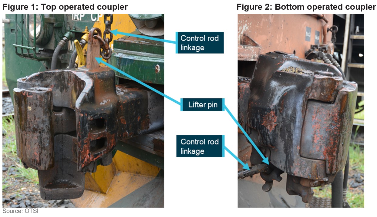
While top operated couplers provide a clear visual cue when the knuckle is unlocked, specifically, the lifter pin is significantly raised above the coupler assembly (Figure 1), the range of movement and vision of a lifter pin on a bottom operated coupler is markedly reduced (Figure 2).
Due to significant limitations in visual cues, a positive stretch test, particularly of bottom operated couplers, is essential for verifying that the knuckle is locked at the conclusion of a coupling manoeuvre.
To registered operators and maintenance organisations ofpiston engine aircraft
A proactive approach to replacing O-ring seals before they deteriorate to the point of failure, may avoid fluid leakage that on this occasion led to an in-flight, fuel-fed, engine fire.
What happened
On 17 October 2022, at about 1345, the pilot of a Mooney Aircraft Corporation M20J aircraft, registered VH‑UDQ, departed Maitland Airport, NSW for a local flight before heading to Luskintyre Airfield, NSW. After the aircraft completed an orbit of the airfield, witnesses reported seeing smoke trailing the aircraft as it descended. VH‑UDQ collided with terrain about 330 metres (0.2 NM) short of runway 30 and burst into flames. The aircraft was destroyed. The pilot survived the collision, but later succumbed to injuries associated with the post‑impact fire.
Why did it happen
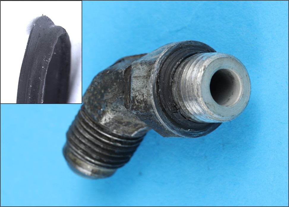
Following the accident, pressure testing of the engine driven fuel pump revealed a fluid leak from the pump outlet fitting that supplied the engine fuel control unit. The ATSB’s analysis indicated that the condition of the O-ring sealing the fitting had deteriorated with age, with evidence of loss of pliability, permanent deformation and the presence of surface defects. Examination of aircraft records revealed that the pump had been in service for just over 29 years, and had likely remained undisturbed for maintenance related purposes throughout that period.
Age-affected O-ring seal of fluid carrying fitting with inset image displaying permanent deformation of the seal
Safety advisory notice
AO-2022-049-SAN-001: A proactive approach to replacing O-ring seals before they deteriorate to the point of failure, may avoid fluid leakage that on this occasion led to an in-flight, fuel-fed, engine compartment fire. The ATSB advises aircraft owners, registered operators and maintenance personnel to consider replacement of the O‑ring seals of fluid carrying components, when examination of aircraft records identify components that have remained undisturbed for significant periods of time.
Advisory material published by the Civil Australian Safety Authority differentiates between ‘on-condition’ and ‘fit‑until-failure’ maintenance principles (Airworthiness Bulletin AWB 02-1) however O‑ring seals may not be specifically identified as a sub-set of elastomer type products requiring periodic attention for potential loss of function (AWB 85-004).
Replacing O-ring seals before they deteriorate
Unlike engine hoses and rubber isolation mounts, some elastomers contained in engine compartments may not be readily inspected for signs of deterioration or degradation due to age, during routine engine maintenance. In practice, reliance on the absence of a leak when inspecting an engine may not be a reliable indicator of O-ring serviceability across all engine power settings.
Although further analysis is required to establish the contributing factors in this accident, the circumstances as far as they are known at this time suggest that the helicopter encountered turbulence, followed by a low‑g condition immediately prior to the in‑flight break‑up. The ATSB therefore considers it prudent to draw attention to Robinson’s advice regarding flight in turbulent conditions and avoidance/recovery from low‑g flight until such time as the factors that contributed to this accident can be fully established.
Awareness of conditions likely to produce turbulence, and slowing down prior to encountering turbulence, could increase the time available to recognise and respond to a low-g condition in Robinson Helicopters.
What happened
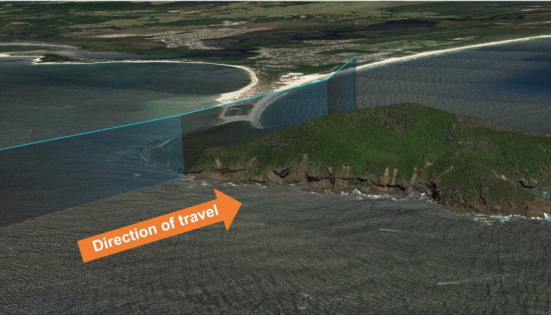
On 26 October 2023, the pilot of a Robinson R66 helicopter encountered mechanical turbulence flying over Yacaaba Headland, NSW, which resulted in a rapid loss of control and subsequent in-flight break-up.
Why did it happen
Prior to encountering turbulence, the aircraft was traveling at an airspeed which may have increased the severity of the aerodynamic effects of the turbulence. This possibly reduced the time available for the pilot to recognise and recover from a low-g condition, and avoid a loss of control.
Safety advisory notice
AO-2023-051-SAN-001: The ATSB advises all operators of Robinson helicopters to be aware of the possibility of mechanical turbulence and avoid it whenever possible. If it is not possible to avoid flying through an area where mechanical turbulence is anticipated, reduce airspeed to 60–70 kt in accordance with Robinson Safety Notice 32, prior to encountering turbulence.
Slow down prior to suspected turbulence
Robinson Helicopters’ handling characteristics in low-g and turbulent conditions are well documented and detailed in Robinson Helicopter Safety Notices SN-11 & SN-32 respectively. In both cases an increased airspeed affects the severity of the resulting aircraft response, and increases the likelihood of mast bumping and in-flight break-up.
It is possible that, at high airspeeds, an encounter with turbulence may produce a reaction that requires an immediate and decisive response from the pilot to ensure the safety of flight. As outlined in Robinson Safety Notice 11, a low‑g (weightless) condition can result in a powerful right roll. In such circumstances, ‘The rotor must be reloaded before lateral cyclic can stop the right roll. To reload the rotor, apply an immediate gentle aft cyclic, but avoid any large aft cyclic inputs.’
As airspeed increases, the time available for the pilot to recognise and respond to undesirable aircraft states is significantly reduced.
Pilots are reminded to remain vigilant at all times and to continuously assess conditions to identify the possibility for turbulence. Where any doubt exists, pilots should reduce airspeed prior to entering an area with potential for turbulence to reduce the effects of, and increase the available response time to, an upset condition.
To Robinson R22 and R44 maintainers, operators, and pilots
More data is needed to understand ongoing engine cylinder issues in R22 and R44 helicopters
What happened
On the morning of 6 August 2022, the pilot of a Robinson R22 Beta II was flying at about 500–600 ft en route to conduct aerial mustering in northern Queensland. After some time in cruise, the helicopter suddenly began to ‘shake and vibrate’. In response, the pilot conducted an autorotation, flaring the aircraft just above the trees in a heavily wooded area. The aircraft collided with trees and was destroyed. The pilot was uninjured, and there was no fire.
Why did it happen
The ATSB found that the engine issues prompting the pilot to attempt a forced landing were likely the result of carbon deposits that had accumulated on the valve stem of the no. 2 cylinder exhaust valve and within its guide, reducing clearance to less than the specified minimum. The reduced clearance likely resulted in the valve binding in the guide, and not fully closing.
R22 and R44 cylinder durability
R22 and R44 series helicopters have been used extensively in northern Australia for the aerial mustering of livestock. From around 2016, some operators reported an increase in engine cylinder failures due to low compression. Undetected loss of compression on one or more cylinders can lead to a reduction in power, and the possibility of an in-flight emergency.
Significant work was undertaken to determine the reasons for these cylinder failures, and multiple factors were identified. However, CASA Airworthiness Bulletins AWB 85-024 – Robinson R22/R44 Engine Exhaust Valve and Valve Guide Distress and AWB 85-025 – Robinson R22/R44 Engine Intake Valve and Valve Seat Distress (Civil Aviation Safety Authority, 2018) noted that:
A clear understanding of all potential causative factors needs to be established before any permanent solutions can be implemented through design, manufacturing, operational or maintenance changes.
In 2019, the Lycoming Cylinder Durability Investigation Group (LCDIG) was formed to gather further information, collecting defect reports though form 1529 that is available at:
AO-2022-038-SAN-01: The ATSB strongly encourages maintainers, operators, and pilots of Robinson R22 and R44 helicopters fitted with Lycoming O-320, O-360 and O-540 series engines to complete a Lycoming cylinder durability investigation group defect report form 1529 any time engine cylinder issues are identified.
To helicopter medical transport operators and hospital helicopter landing site operators
Medical transport operators should engage with the owners and operators of hospital helicopter landing sites to ensure local procedures are sufficient to mitigate the risk of rotorwash associated with larger aircraft.
What happened
The ATSB found that following the introduction of larger helicopters into medical transport operations, there has been an increase in rotor wash related injuries at hospital HLS.
Why did it happen
Flight crew were not aware of pedestrians in the vicinity of the hospital helicopter landing site at the time. If the recommended rotor wash exclusion area had been applied at each HLS, it would have reduced the risk of the pedestrians being injured.
: The Australian Transport Safety Bureau strongly encourages operators of hospital helicopter landing sites, and helicopter medical transport operators using those landing sites, work together to review the adequacy of existing risk controls to ensure pedestrians are adequately protected from the increased rotor wash associated with larger helicopters.
Managing the risk of rotor wash
From the identified common factors associated with rotor wash incidents, the flightpath is the only element that can be managed by the pilot in accordance with the operator’s procedures. However, pilots may be unaware of the presence of pedestrians in the vicinity of a hospital HLS. To enable the continued safe use of these facilities, hospital HLS owners and helicopter operators should ensure pedestrians are not affected by rotor wash by implementing appropriate risk controls for their HLS in addition to the helicopter operating procedures. Controls may include physical barriers, warning devices such as sirens, lights, high visibility warning signs, painted lines on nearby public thoroughfare to alert pedestrians to the rotor wash danger area, an inspection schedule for the HLS facility and surrounding area, and establishing a closed-loop reporting system.
To manufacturers of constant wear lifejackets and certification authorities
Fitment of constant wear lifejackets with seatbelts in aircraft
Constant wear lifejackets, including pouch style lifejackets, must not interfere with the proper fitment of aircraft seatbelts. It is imperative that seatbelts are fitted correctly. Not wearing a seatbelt, or wearing it improperly, can significantly increase the risk of serious or fatal injury in the event of an accident.
What happened
On 2 January 2023, Sea World Helicopters was conducting a series of short scenic flights from its base at Sea World on the Gold Coast, Queensland. The operator was using 2 Eurocopter EC130B4 helicopters which were operating from separate helipads about 220 m apart.
As one helicopter approached the southern helipad to land, another took off from the helipad to the north. The helicopters collided mid-air at about 130 ft. One helicopter proceeded to a controlled landing on a sandbar, the pilot and two passengers were seriously injured. The other helicopter fell uncontrolled to the edge of the sandbar. There were 3 passengers seriously injured and the pilot and three passengers were fatally injured. While some occupants of this aircraft survived, the ATSB would categorise the impact with terrain for that helicopter as likely not survivable (the occupants were not expected to survive the impact).
Safety equipment
Seatbelts
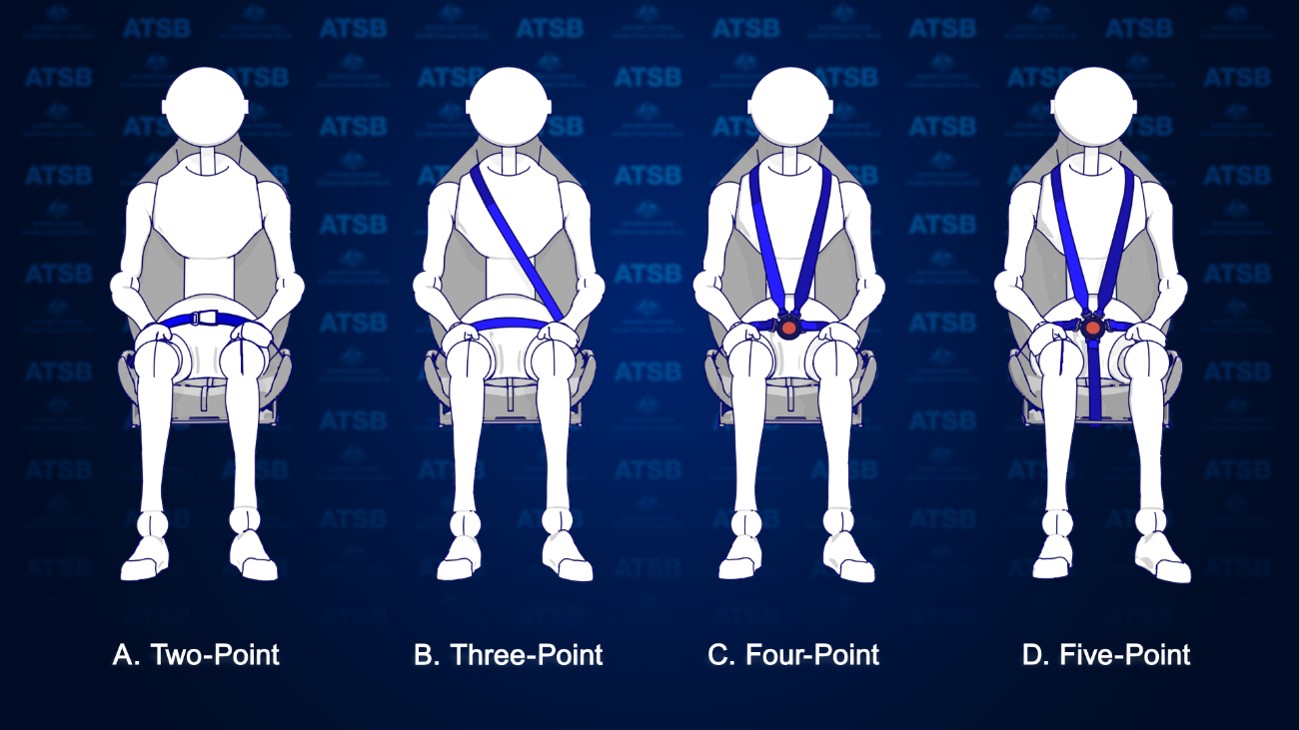
There are several types of seatbelts used to restrain passengers in aircraft. The most common type that passengers are exposed to are lap belts (2-point restraints) like those used on large passenger aircraft. There are also 3-point, 4-point and 5-point restraints, which are more prevalent in light aircraft, that have an added safety harness for the upper body (Figure 1). In the case of the helicopters involved in the accident, all seats were fitted with 4-point restraints.
Figure 1: Types of aircraft seatbelts
Source: ATSB
To be effective in an accident, seatbelts must be fitted correctly. Not wearing a seatbelt or wearing it improperly can result in serious injury or fatalities. For example, the fatality rate in accidents in Canada involving seaplanes has been shown to be 3 to 4 times higher for occupants who don’t wear a restraint system properly over those that do.[1]
For seatbelts to be effective, regulatory and manufacturer guidance advise:[2]
Seatbelts must not be twisted, they must be fitted without slack, and adjusted to fit as tightly as comfort allows.
The lap portion of the seatbelt must be placed low and tight across the hips.
Seatbelts must not be fitted across the abdomen as this can cause internal injuries or result in the person sliding out the bottom of the harness (submarining), nor should they be fitted across the thighs, or the seatbelt will not effectively prevent forward movement.
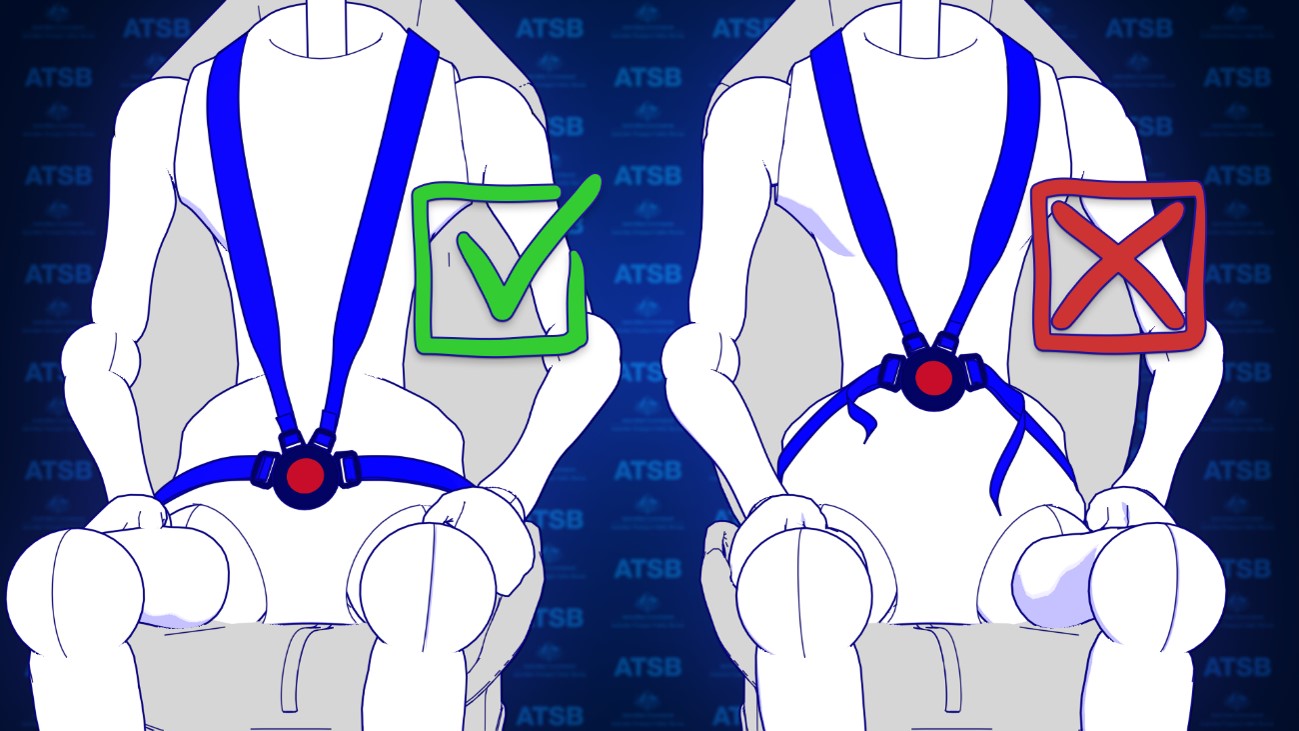
For the fitment of 4-point restraints, the lap belt portion of the restraint should be fitted and adjusted first before the shoulder harness. This is to prevent the shoulder harness from pulling the lap belt off the hips.
Figure 2: Correct and incorrect fitment of 4-point harnesses
Source: ATSB
Constant wear lifejackets
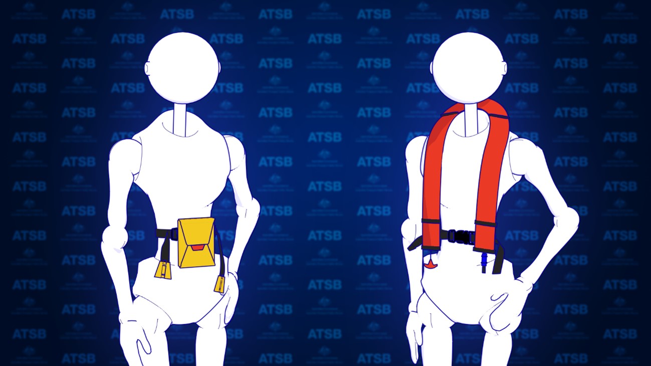
Aviation lifejackets are inflatable and can be packaged in many forms. To ensure passengers have access to a lifejacket in a time limited situation, lifejacket manufacturers have produced lifejackets known as constant wear lifejackets. Constant wear lifejackets come in two packaging forms. There is a yoke style which is worn like a vest (Figure 3, right) and a pouch style which is worn around the waist (Figure 3, left) but readily pulled over the head of the occupant when required. To meet the required aviation standards, operational instructions must be provided in writing and be printed on the lifejacket.
Figure 3: Example of pouch (left) and yoke (right) style constant wear lifejackets
Source: ATSB
What the ATSB found
Passenger photographs and footage from inside both helicopters identified that some passenger seatbelts were not fitted correctly. This was due, in part, to interference caused by the location of the constant wear pouch style lifejackets that were being worn by passengers. The operator’s pre-flight passenger safety briefing video also depicted incorrect use of the 4-point restraint while wearing the lifejacket. The operator’s ground crew, who had been assigned responsibility for the fitment of passenger seatbelts, also indicated in interview that they were not aware that fitting the seatbelt over or above the lifejacket may reduce its effectiveness.
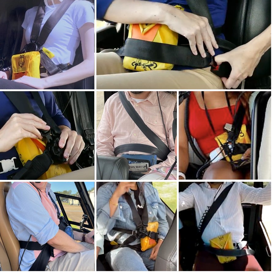
To establish the extent of the issue the ATSB conducted a review of helicopter tourism operations in Australia and around the world through social media. The ATSB found that similar practices of incorrect fitment of seatbelts with constant wear pouch style lifejackets were prevalent. Many relevant social media photos reviewed by the ATSB (see Figure 4 for some examples) showed the seatbelt buckle was positioned above the lifejacket pouch or over it. This meant that the lap belt portion of the seatbelt was not low and tight across the passenger’s hips and the seatbelt buckle was positioned either over the lifejacket (creating slack) or above the lifejacket, close to the passenger’s sternum increasing the risk of injury. This suggests there is a common lack of understanding in the helicopter tourism community about how to integrate constant wear lifejackets with seatbelts, so as not to reduce their effectiveness. Although social media images reviewed by the ATSB predominately showed interference caused by a ‘pouch style’ constant wear lifejacket, the ‘yoke style’ constant wear lifejacket more often used by pilots and commercial passengers, was also shown to have the potential to interfere with the aircraft seatbelt.
For constant wear lifejackets, it is reasonably foreseeable that they would be worn seated in an aircraft and while using the aircraft’s seatbelt. The ATSB reviewed existing guidance from all known manufacturers of aviation constant wear lifejackets, as well as from the Civil Aviation Safety Authority and a range of international aviation regulators. Beyond stating that lifejackets should not interfere with other aircraft equipment, lifejacket manufacturers and regulatory authorities have not provided any readily available guidance to assist helicopter operators on how to position a pouch or yoke style constant wear lifejacket so as not to interfere with an aircraft seatbelt. Additionally, there are no requirements to provide such instructions in the relevant standards.
Figure 4: Examples of lifejacket interference
Sources: Safety briefing videos from YouTube and the operator, and other social media
The ATSB encourages manufacturers of constant wear lifejackets to provide operating instructions and/or guidance material to operators of aircraft on how to wear and use a constant wear lifejacket with a seatbelt (of any configuration) such that it does not interfere with the performance of the seatbelt during an accident.
Further,the ATSB encourages certification authorities to modify lifejacket standards to include the requirement for instructions on how to wear constant wear lifejackets while seated and wearing a seatbelt.
Beechcraft Baron heater fuel supply line inspection
The ATSB is encouraging Baron operators to inspect the heater fuel supply line and nearby wiring in the aircraft cockpit to reduce the risk of an in-flight fire.
What happened
At approximately 0835 on the morning of 16 April 2022, the pilot of a Beechcraft B58 Baron registered VH-NPT commenced an approach to Runway 12 at the East Kimberley Regional Airport near Kununurra. Upon selection of the landing gear to the down position the pilot reported multiple unusual indications, the gear failed to extend and smoke started to emerge from forward of the pilots side circuit breaker panel. By the time the pilot had declared a PAN, flame was emerging from the same location as the smoke. The pilot expended the aircraft’s fire extinguisher but the fire returned. Smoke and flame continued to effect the pilot until the aircraft collided with terrain where it was consumed by a significant post impact fire. The pilot sustained serious injuries and the single passenger onboard was fatally injured.
Related Occurrence
During the initial phase of the investigation the ATSB identified a similar occurrence that had been investigated in 2014 (
). The investigation of the in-flight cockpit fire found that electrical wiring had chaffed through the heater fuel supply line causing it to arc and burn a hole in the fuel line. This provided an ignition source and accelerant for the fire.
Why did it happen
Both the heater fuel line and the aircraft wiring of NPT were consumed by the post impact fire, and an examination was not possible. However, the location, initiation and severity of the fire is similar to the incident detailed in AO‑2014‑040. As such, while the specific circumstances of the fire initiation and acceleration remain under investigation, in the interest of transport safety, the ATSB has issued this safety advisory notice.
Manufacturer Response
In response to the advanced release of this ATSB SAN the manufacturer advised that there is a potential for chafing of wiring across several Beechcraft models including the Baron. Model Communiqué 116 references wire chafing reports in the Beechcraft Bonanza but the communiqué states that the protection of wires from chafing damage is applicable to all Beechcraft models.
Safety advisory notice
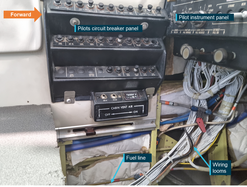
AO-2022-026-SAN-001: The ATSB encourages operators of Beechcraft Baron aircraft to conduct a detailed inspection of the heater fuel supply line and wiring in its vicinity. The examination should focus specifically on the area below the pilot’s circuit breaker panel and areas forward of this under the instrument panel. Any identified issues should be reported to CASA (via the defect reporting system) and the manufacturer.
The ATSB encourages Baron operators to review the Electrical Wire Chafing Protection section in Model Communiqué 116 (See attachment A) put out by Beechcraft in June of 2008, which is applicable to all Beechcraft models.
The ATSB further encourages operators to review the anti-chafing provisions within the relevant aircraft maintenance manual (see 20-04-00-001 – Electrical Wiring – Description and Operation) to ensure serviceability of anti-chafing materials and replace or fit, as necessary. Specific consideration should be given to wiring in the vicinity of lines carrying flammable liquids.
ATSB comment
The ATSB notes similarities in several Beechcraft models, that utilise fuel lines running through the cockpit. While a review of ATSB data does not support the broadening of the SAN to include other aircraft models, chafe protection should be applied to wiring as per the manufacturers' requirements and particular care should be taken when wiring is in the proximity of lines carrying flammable liquids.
Area of concern in an exemplar Baron B58 showing the location of the fuel line and wiring looms. Inspection should encompass any areas along the fuel line where it may contact wiring looms.
All aircraft types do not spin and recover in the same way. Know your aeroplane type, what recovery techniques will work and what recovery techniques will not work.
What happened
On 23 June 2021, while conducting spin entry and recovery training from 5,800 ft above ground level, the Cessna A150M Aerobat did not fully recover from a spin to the left before impacting terrain.
Factors uncovered during the investigation
The aerobatics instructor was experienced in conducting spins, primarily in the Pitts Special aircraft type. However, it was likely that they had no experience in spinning a Cessna A150 Aerobat or any similar variant.
The instructor’s theoretical spin training provided to the aerobatic student pilot (and another student at the same time) did not include instruction on the recovery technique as prescribed in the Aerobat pilot’s operating handbook (POH). Further, the ATSB established that it was likely the instructor intended to practice 2 spin recovery techniques (Mueller/Beggs and PARE). The technique broadly known as the Mueller/Beggs recovery method, has been shown to not recover a Cessna A150 Aerobat established in a spin to the left. However, the PARE method was similar to Aerobat POH method, with less emphasis on the brisk full forward movement of the control yoke.
: The ATSB strongly encourages all aerobatic pilots and aerobatic flight instructors to be aware:
the Mueller/Beggs method of spin recovery does not recover all aircraft types from a spin
the Mueller/Beggs spin recovery method limitations should be emphasised during spin theory training
the Mueller/Beggs method of spin recovery will not recover a Cessna A150 Aerobat or similar variants from a spin in some circumstances
they should review the pilot’s operating handbook of the aircraft type that they intend to operate for the recommended spin recovery technique
prior to doing spins in any model aircraft, pilots should obtain instruction and or advice in spins from an instructor who is fully qualified and current in spinning that model.
On 14 February 2022, the pilot of a Garlick Helicopters UH-1H was providing aerial firefighting support to combat the ‘Labrina’ bushfire that had developed north of Launceston, Tasmania. That afternoon, the pilot was tasked to firebomb a localised hot-spot that had developed within the fireground. Witnesses both on the ground, and within a nearby helicopter, observed the early release of the water load from the underslung bucket, before the UH-1H commenced a left turn and descended toward nearby open terrain. The helicopter was then observed to slow and enter a hover, then rapidly yaw, before descending and impacting terrain. The pilot was fatally injured, and the helicopter was destroyed.
Why did it happen
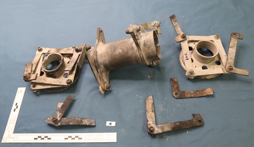
The ATSB’s on-site examination of the wreckage found anomalies with the helicopter’s main drive shaft, identified as a KAflex and manufactured in the United States by Kamatics Corporation (Kamatics), that transmits engine power to the transmission. The shaft was found to have fragmented during the accident sequence, with 4 of the flex-frame attaching hardware (nuts, bolts, and their washers) and portions of the flexible frame elements unable to be accounted at the accident site. The ATSB subsequently commenced a detailed technical examination of the KAflex shaft assembly and importantly, severe frictional and wear damage was identified to have occurred to one portion of the shaft. The results of that work was presented to Kamatics and the Civil Aviation Safety Authority (CASA).
While the ATSB’s investigation of this accident and further technical examination of the KAflex shaft remain ongoing, the manufacturer advised that the presence of the frictional damage was evidence that the shaft had entered fail-safe mode during operation. The frictional damage was consistent with other KAflex shafts that had entered fail-safe mode following the release of flex-frame attaching hardware, or, when one of the flexible frame elements had fractured during operation.
Kamatics further advised that, although the fail-safe feature is intended to allow for uninterrupted drive for up to 30 minutes of helicopter operation, if a flex-frame attachment bolt were to release, the time before complete shaft failure may be significantly reduced. Reports from other UH-1H accidents involving a partial KAflex shaft failure identified that the off-centre operation and corresponding imbalance can produce sudden loud noises, vibrations, and control difficulties for the pilot.
Kamatics also stated that, while the United States Federal Aviation Administration airworthiness directive AD 2021‑26‑16 became effective on 25 February 2022 for the inspection and potential replacement of KAflex shafts installed in UH-1H helicopters, some concern remains for shafts identifed in the serial number ranged 0635 and below. The manufacturer is uncertain of the configuration status of this serial number range, whereby these shafts may be fitted with legacy flex-frame attachment hardware that can exhibit signs of deterioration, increasing the potential for shaft failure.
While the specific circumstances of this accident are still under investigation, the ATSB has issued the following safety advisory notice to advise UH-1H operators and maintainers of the potential safety concern.
The ATSB advises operators of UH-1H helicopters to note the preliminary details of this accident, the content of AD 2021‑26‑16 and CASA Airworthiness Bulletin AWB 63-004, and to look for the presence of:
corrosion
fretting
frame cracking
missing or damaged flex-frame attaching hardware
during all inspections of the KAflex drive shaft. Any identified defects should be notified to the Civil Aviation Safety Authority and the ATSB.
Additionally, operators should be aware of Kamatics concern of a certain serial number range of shafts for the UH‑1H helicopter that may be fitted with legacy flex-frame attachment hardware. Kamatics (chris.prain@kaman.com) should be contacted if a shaft in the affected serial number range (0635 and below) is identified.
Fragmented KAflex from the accident helicopter, source ATSB
To Rollingstock Operators Number: RO-2020-022-SAN-002
Unknown functions in locomotive braking systems
An ongoing investigation, conducted by NSW’s Office of Transport Safety Investigations on behalf of the Australian Transport Safety Bureau, highlights risks associated with misunderstood functionality of locomotive braking systems. Locomotive drivers require a clear understanding of the braking systems on all the locomotives they are operating.
What happened
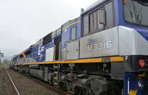
On 15 December 2020 a loaded grain train derailed whilst descending the 1 in 30 grade rail line between Robertson and Unanderra, NSW.
Runaway locomotives (Source: ATSB)
Why did it happen
During the descent, the train driver lost control of the train. As the train continued to increase speed, the driver did not apply the emergency brake, believing an emergency application of the air brake would disengage the dynamic brake.
The ATSB identified that the locomotives involved had an electronic braking system that allowed the dynamic brake to remain active while the emergency brake was applied. This feature was unknown to the operator and the train driver.
While the specific circumstances of this incident and contributing factors are still under investigation, the ATSB has issued this safety advisory notice to advise rolling stock operators and operational staff of a potential broader industry safety concern.
The ATSB identified similar functional changes on locomotive braking systems more broadly across industry that were also unknown to Rollingstock Operators.
Importantly, dynamic brake functionality is not consistent across all locomotives with electronic braking systems. While some locomotives will disengage the dynamic brake when an emergency brake application is made, in other locomotives the dynamic brake remains functional.
Safety advisory notice
RO-2020-022-SAN-002: The ATSB advises that all Rollingstock Operators (RSO) should review specifications and test locomotives under their control to understand how the braking systems are configured. RSOs must communicate this knowledge through their organisation’s procedures and training material to ensure train crew knowledge and competence in operating various locomotive braking systems.
Ensure understanding of locomotive specifications and operation
Rollingstock Operators must have a complete understanding of the operation of their locomotives. Identifying safety critical information from technical specifications and testing locomotive operations must be completed and used to inform the organisation’s procedural and training material.