The Civil Aviation Authority of Vanuatu (CAAV) investigated a fuel starvation and collision with terrain accident involving Britten-Norman Islander BN2A-20, YJ-AT2, 6 km east-south-east of Port Vila International Airport, Vanuatu, on 15 July 2024. The CAAV requested assistance from the Australian Government represented by the ATSB.
To facilitate this support and to provide the appropriate protections for the information, the ATSB appointed an accredited representative in accordance with paragraph 5.23 of the International Civil Aviation Organization Annex 13 and commenced an investigation under the Australian Transport Safety Investigation Act 2003.
On 14 August 2025, the CAAV released its final report into this accident. This report is available here.
Any enquiries relating to the investigation should be directed to the CAAV.
The Transportation Safety Board (Junta de Seguridad en el Transporte - JST) of Argentina requested technical assistance from the ATSB to support its investigation into the collision between 2 trains on the railway bridge over Figueroa Alcorta Avenue, Palermo, Buenos Aires, that occurred at about 1030 local time on 10 May 2024.
Passenger train 3353 and work train T3021 were both operated by the State Railway Operating Company. Train 3353 was made up of locomotive B951 and 7 passenger cars. The T3021 work train consisted of locomotive 1000 and one car without passengers. The collision resulted in damage to the track infrastructure and rolling stock. It was reported by the JST that there were about 90 injuries among passengers and railway personnel.
To facilitate this support and to provide the appropriate protections for the information, the ATSB commenced an investigation under the Transport Safety Investigation Act 2003. At the request of the JST, the ATSB provided feedback in September 2024 on their preliminary investigation report. No further requests for follow-up assistance have been received. The ATSB's support to the JST has now been completed.
The JST is responsible for the investigation and release of the final investigation report regarding this accident. Once completed, a copy of the report can be accessed here.
Any enquiries relating to the investigation should be directed to the JST: info@jst.gob.ar
Occurrence summary
Investigation number
RE-2024-001
Occurrence date
10/05/2024
Location
Palermo, Autonomous City of Buenos Aires, Argentina
On 8 June 2024, a de Havilland Canada DHC-6 Twin Otter, registered P2-BBM, had a runway excursion at Kikori Airstrip, Papua New Guinea.
The Papua New Guinea Accident Investigation Commission (AIC) is investigating the occurrence. AIC has requested assistance from the ATSB to decompress recovered flight data.
To facilitate this support and to provide the appropriate protections for the information, the ATSB appointed an accredited representative in accordance with paragraph 5.23 of the International Civil Aviation Organization Annex 13 and commenced an investigation under the Australian Transport Safety Investigation Act 2003.
The ATSB provided the decompressed file to the AIC on 19 June 2024.
Any enquiries relating to the investigation should be directed to AIC.
Occurrence summary
Investigation number
AA-2024-007
Occurrence date
08/06/2024
Location
Kikori Airstrip, Papua New Guinea
State
International
Investigation type
Accredited Representative
Investigation status
Completed
Mode of transport
Aviation
Aviation occurrence category
Runway excursion
Aircraft details
Manufacturer
De Havilland Canada/De Havilland Aircraft of Canada
On 19 May 2024, a Tecnam P2600T aircraft was being operated on a flight from Salakanagara Tanjung Lesung airfield, Banten, Indonesia to Pondok Cabe Airport, Jakarta, Indonesia, with 3 people on board. At 1344 local time, on approach to Pondok Cable Airport at an altitude of 1,000 ft, the pilot declared a MAYDAY. Shortly after, the aircraft collided with terrain near a main road. All occupants were fatally injured.
The Indonesian National Transportation Safety Committee (NTSC) is investigating this occurrence.
NTSC has requested assistance from the ATSB to recover data from a damaged GPS unit. To facilitate this support and to provide the appropriate protections for the information, the ATSB appointed an accredited representative in accordance with paragraph 5.23 of the International Civil Aviation Organization Annex 13 and commenced an investigation under the Australian Transport Safety Investigation Act 2003.
The ATSB has completed its work recovering the GPS data. A copy of the data and a report detailing the work undertaken by the ATSB was provided to the NTSC on 19 July 2024.
Any enquiries relating to the investigation should be directed to NTSC.
The Transport Accident Investigation Commission (TAIC) of New Zealand has commenced an investigation into a runway excursion involving an Airbus A320, registered VH-VFF, at Christchurch Airport, New Zealand, on 30 May 2024.
During descent while conducting a passenger flight from Auckland, New Zealand, to Christchurch, the crew received a warning for one of the hydraulic systems, affecting the nose wheel steering. On landing, the aircraft had a runway excursion and made contact with a runway sign causing damage to the right engine. There were no reported injuries to crew or passengers and minor damage to the aircraft.
The TAIC requested assistance and the appointment of an accredited representative from the ATSB. To facilitate this support and to provide the appropriate protections for the information, the ATSB appointed an accredited representative in accordance with paragraph 5.23 of Annex 13 to the Convention on International Civil Aviation and commenced an investigation under the Australian Transport Safety Investigation Act 2003.
On 19 March 2026, the TAIC released the final investigation report into this accident. Accordingly, the ATSB has concluded its involvement in the investigation. A copy of the report can be obtained from the TAIC at: https://taic.org.nz/inquiry/ao-2024-004.
Any enquiries relating to the investigation should be directed to the Transport Accident Investigation Commission at https://taic.org.nz/.
Occurrence summary
Investigation number
AA-2024-005
Occurrence date
30/05/2024
Location
Christchurch Airport, New Zealand
State
International
Investigation type
Accredited Representative
Investigation status
Completed
Mode of transport
Aviation
Aviation occurrence category
Runway excursion
Occurrence class
Serious Incident
Aircraft details
Manufacturer
Airbus
Model
A320-232
Registration
VH-VFF
Serial number
5039
Sector
Jet
Operation type
Part 121 Air transport operations - larger aeroplanes
On 18 February 2024, during a winch launch at approximately 700 feet above ground level, the right wing of the LAK-12 glider failed, resulting in a collision with terrain. The pilot was fatally injured.
The New Zealand Civil Aviation Authority (CAA) is investigating this occurrence. CAA has requested assistance and the appointment of an accredited representative from the ATSB.
To facilitate this support and to provide the appropriate protections for the information, the ATSB appointed an accredited representative in accordance with paragraph 5.23 of the International Civil Aviation Organization Annex 13 and commenced an investigation under the Australian Transport Safety Investigation Act 2003.
The ATSB was requested to examine and assess the possibility of recovering data from a damaged memory card. The ATSB x-rayed the memory card to enable an assessment and determined that the internal damage was such that the data was not recoverable by the ATSB.
With the completion of the examination and assessment and the return of the evidence to the CAA, the ATSB has concluded its involvement in the investigation of this accident.
Any enquiries relating to the investigation should be directed to CAA New Zealand.
The United States National Transportation Safety Board (NTSB) is investigating an accident involving an amateur-built Beck Michael J Sonex, registered N920MB, near Auburn Municipal Airport, Washington, United States, at about 1130 local time on 16 January 2024.
The pilot reported that while climbing after take-off, a partial engine power loss occurred, and the aircraft began descending. The pilot then planned to conduct a forced landing on a road straight ahead of the aircraft but several seconds later, the engine regained power enabling a climb. About 40 seconds later, the engine lost all power and the pilot turned the aircraft toward the airport. The aircraft then collided with signage structures and terrain and was substantially damaged. The pilot was not injured.
As part of the investigation, the NTSB identified an Australian-manufactured Rotec Aerosport TBI Mk 1 throttle body in the aircraft wreckage and considered it an item of interest. To support the investigation, the NTSB requested assistance and the appointment of an accredited representative from the ATSB to facilitate manufacturer examination and functional testing of the throttle body.
To facilitate this support and to provide the appropriate protections for any relevant information, the ATSB appointed an accredited representative in accordance with paragraph 5.23 of the International Civil Aviation Organization Annex 13 and commenced an investigation under the Australian Transport Safety Investigation Act 2003.
To ensure the integrity of the material evidence and to provide independent oversight, ATSB personnel were required to be present for the Australian manufacturer’s examination and testing of the throttle body. However, Rotec Aerosport would not permit ATSB personnel to be present and therefore, the NTSB elected not to proceed with the testing.
As no further involvement has been requested, the ATSB has closed this investigation.
On 23 February 2024, an Alliance Airlines Embraer E190-100 aircraft, registered VH-UYI, was operating a scheduled passenger flight, IE700, on behalf of Solomon Airlines, from Honiara, Solomon Islands to Brisbane, Queensland. On board were the captain as pilot monitoring (PM), first officer as pilot flying (PF), 2 cabin crew and 66 passengers.
Prior to conducting the Before-start checklist, the left seat pilot (captain) was required to set the aircraft’s speed mode selector, with flight management system (FMS) mode recommended. While the crew’s intention was to depart in FMS speed mode, undetected by either flight crew, this step was omitted, and the speed selection remained in manual mode.
As the aircraft was climbing through 1,200 ft, vertical flight level change (VFLCH) mode engaged in the FMS. Once in VFLCH, the flight director (FD) commenced targeting the manual target speed which, at that time, was 125 kt.
Over the next 20 seconds, the aircraft’s speed gradually reduced and the pitch gradually increased to target the manual speed. Detecting that the aircraft was not accelerating, the PM assessed there was too much drag on the aircraft and retracted one stage of flap. The flap retraction resulted in a visual low airspeed cockpit alert.
Shortly afterwards, the crew detected the speed mode was incorrectly set, and changed the speed mode to FMS mode, at which time the aircraft commenced accelerating to the correct target airspeed.
What the ATSB found
The ATSB determined that the left seat pilot (captain) unintentionally left the speed selection in manual mode instead of flight management system mode with no manual speed set. The manual speed mode selection was not detected by either flight crew member, resulting in the aircraft decelerating after VFLCH mode engaged.
While the captain was monitoring traffic, weather and making a radio broadcast, the first officer was not effectively monitoring the airspeed and as a result, did not initially detect the aircraft decelerating. Having assessed that the low airspeed was due to excessive drag, the captain retracted one stage of flap while below the minimum flap target speed, resulting in the aircraft entering a low-speed state.
Alliance Airlines’ standard operating procedures manual (SOPM) included a step of initially selecting the speed knob to ‘manual’ in its pre-flight procedures, despite that mode very rarely being used for take-off. This increased the risk of flight crews departing with the manual speed mode unintentionally selected. The ATSB also identified that Alliance’s right seat pilot shutdown flow was undocumented and not in accordance with the manufacturer’s guidance.
Additionally, Embraer's airplane operations manual was inconsistent with its standard operating procedures manual in regard to setting the speed knob to manual in the Before start procedures.
Likely due to a training deficiency, Alliance Airlines flight crews' conduct of the Before startprocedures and Pre-take-off brief review were not being performed effectively to ensure the speed selector knob was correctly set and checked, which increased the risk of a low-speed event after take-off.
A review by the operator of flight data found that in 112 flights operated over a 30-month period, flight crew had also not selected, or detected, the speed selector knob in manual mode prior to commencing the take-off run. In 76 of these events, flight crew were changing the speed selector knob setting during the take‑off run, increasing the risk of distraction during a critical phase of flight.
What has been done as a result
Action was taken by Alliance Airlines to address the safety issues identified in this investigation, including:
E190 SOPM pre-flight procedures have been amended so the left seat pilot selects FMS mode to mitigate unintentionally departing in manual speed mode.
The practice of the right-seat pilot setting manual speed and 80 knots during the after‑shutdown flow will be discontinued. Recurrent training and check events will reinforce compliance with the correct procedure.
Training and procedural guidance to reinforce the correct setting and verification of the speed mode selector knob is being enhanced. Flight crews will receive targeted refresher training through a dedicated simulator training module, emphasising correct procedural discipline for conducting pre-take-off reviews.
Flight crews will receive targeted instruction emphasising that no adjustments to the speed selector knob are to be made during the take-off roll. This will be reinforced during initial, recurrent and line check assessments. Compliance with this policy will be monitored through the collection and analysis of flight data and will be assessed during recurrent simulator training and annual line proficiency checks.
Proactively, Alliance Airlines has also:
Issued an article to flight crew highlighting that at the completion of the before start duties, the left seat pilot should apply the technique of selecting ‘TOGA, TARA, SPEED’, followed by confirmation of the relevant modes and settings on the primary flight display, prior to calling for the completion of the Before start checklist.
Advised that a dedicated training module will be incorporated into recurrent simulator cyclic training exercises commencing 1 January 2025. This module will include a review of this occurrence, its root cause, and a reinforced focus on correct procedures and techniques to prevent reoccurrences.
Advised that during recurrent line check events, there will be an added emphasis on reviewing and ensuring adherence to the correct procedures and techniques.
Finally, Embraer advised that it proposes to align the contents of the AOM and SOPM in the first half of 2025, likely removing reference to selection of manual mode in the Before start procedure.
Safety message
This incident highlights how important continuous attention to the modes displayed on the primary flight display is to situation awareness. An ICAO safety advisory on Mode awareness and energy state management aspects of flight deck automation stated that loss of mode awareness and mode confusion have been identified as factors in several major accidents around the world. Further, that mode confusion can often result in flight crews' mismanagement of an aircraft's energy state, such as the low-speed state that occurred in this incident. The circular recommended that at any time an aircraft does not follow the desired vertical or lateral flight path, or airspeed, flight crew should adapt the level of automation to the task and/or circumstances, or revert to hand flying or manual thrust/throttle control, if required.
The circular also identified inadequate training and system knowledge as a key factor contributing to mode confusion. In this case, training in quick identification of mode indications, including speed display colours during pre-take-off checks, would reduce the likelihood of a similar incident occurring.
The investigation
Decisions regarding the scope of an investigation are based on many factors, including the level of safety benefit likely to be obtained from an investigation and the associated resources required. For this occurrence, a limited-scope investigation was conducted in order to produce a short investigation report, and allow for greater industry awareness of findings that affect safety and potential learning opportunities.
The occurrence
On 23 February 2024, an Alliance Airlines Embraer E190-100 aircraft, registered VH-UYI, was operating a scheduled passenger flight, IE700 on behalf of Solomon Airlines, from Honiara, Solomon Islands to Brisbane, Queensland. On board were the captain as pilot monitoring (PM), first officer as pilot flying (PF),[1] 2 cabin crew and 66 passengers. The flight was scheduled to depart at 1400 local time, but due to several delays (see the section titled Pre-departure delays), departed at 1507.
As the crew were preparing the aircraft, the captain identified that they were likely to encounter a thunderstorm on the track of the planned standard instrument departure (SID). The captain advised that, in order to avoid it, they suggested to the first officer that they conduct a visual departure. However, the first officer reported being ‘comfortable’ with the weather and advised their preference to fly the SID, which was then agreed. The SID required that the aircraft initially climb to 1,000 ft, then conduct a 180° left turn to intercept the outbound track.
The operator’s pre-flight procedures required the left seat pilot (LSP) (captain) to set the speed knob to manual mode (see the section titled The operator split the Before start procedures between Pre-flight and Before start procedures). This resulted in a target speed setting of 80 kt.
Prior to conducting the Before start checklist, the LSP was then required to action the Before start flow[2] which again included setting the speed mode, with the flight management system (FMS) mode recommended. While the crew's intention was to depart in FMS mode, undetected by either flight crew, this step was omitted, and the speed mode selection remained in manual.
The flight crew then configured the aircraft for a flap 4 take-off (see the section titled Flaps) due to the warm, humid conditions and the 2,200 m long runway. The PF armed take-off (TO) mode (see the section titled Vertical modes) in the FMS. In that mode, the flight director (FD) (see the section titled Flight guidance control system) displayed a pitch attitude for the crew to manually follow during rotation and the initial climb.[3]
The PF then commenced the take‑off, selecting TOGA[4] power. After the aircraft rotated, the aircraft’s controller logic (see the section title Controller logic) automatically changed the target speed from 80 kt to V1,[5] which was 125 kt. That change in target speed was displayed on the primary flight display (PFD) (in cyan) but was not detected by either flight crewmember.
The PF manually followed the FD guidance for pitch attitude and the aircraft maintained an airspeed of about V2[6] plus 10 kt (144 kt). In accordance with the operator’s standard operating procedures manual, the PF engaged the autopilot at about 1,000 ft, and subsequently, as the aircraft climbed through 1,200 ft, vertical flight level change (VFLCH) engaged (see the section titled Vertical modes). Once in VFLCH, the FD commenced targeting the target speed, which was 125 kt.
A few seconds later, the aircraft entered a 25° left turn to comply with the SID. At about that time, the PF reduced the power from TOGA power to climb power, and the PM diverted their attention to visually assessing weather on the departure route and monitoring the traffic collision avoidance system for other aircraft. Over the next 20 seconds, the aircraft’s speed gradually reduced while the PM made a departure broadcast on the common traffic advisory frequency (CTAF).[7]
The PM recalled that at that stage of the flight the aircraft felt ‘draggy’. In response, they looked at the PFD and saw the airspeed indicating around 134 kt and recognised that the aircraft was not accelerating. The PM instructed the PF to ‘roll out’ of the banked turn, to reduce drag. However, the PF did not follow that instruction, likely due to believing the call to roll out was regarding the weather ahead, which the PF was not concerned about.
The PM recalled further advising the PF ‘you’re not accelerating’, while also being unsure why the aircraft was not accelerating. Knowing that the landing gear was already retracted, the PM retracted flap from 4 to 3 (slats from 25° to 15°) to further reduce the drag. The PF recalled hearing the PM stating that they were selecting flap 3. After the slats were retracted, the speed further reduced to 131 kt and the PF detected the amber pitch limit indicators (see the section titled Pitch limit indicators) on the PFD and alerted the PM accordingly.
The PF then decided to change the speed mode from FMS to manual, to manually increase the airspeed. However, when they went to change the speed selector knob, they detected that it was already in manual mode and so changed the selection to FMS mode. This occurred 21 seconds after the flap handle was moved to the flap 3 detent. Once the speed mode was in FMS mode, the aircraft accelerated to the correct target speed of 190 kt.
Context
Flight crew information
The captain and first officer both held an air transport pilot licence (aeroplane) and a class 1 aviation medical certificate. The captain had accumulated 17,000 flight hours, and the first officer had about 13,000 flight hours of experience.
Both crewmembers reported feeling well rested prior to the flight, however, the captain reported feeling ‘mentally tired’ prior to take-off, following ground-handling and dispatch irregularities and delays.
Airspace information
Honiara Airport operated a flight information service[8], with the surrounding airspace being non‑controlled. That is, the airspace had no active supervision by air traffic control and pilots were responsible for their own separation from other traffic.
Aircraft information
The aircraft was an ERJ 190-100 IGW, manufactured in Brazil in 2006 and issued serial number 19000053. It was registered in Australia as VH-UYI on 24 January 2022. The aircraft was fitted with 2 General Electric Company CF34-10E5 turbofan engines. It had an integrated avionics system with either ‘load 25’ or ‘load 27’ software installed. VH-UYI had load 27 software.
Flight management system and manual speed modes
Flight guidance control system
According to the E190 maintenance manual, the flight guidance control system (FGCS) has 2 relevant functions:
flight director (FD) guidance: The FGCS calculates the FD guidance commands that show on the primary flight display (PFD). The FD is selected by pressing a button on the guidance panel (GP).
autopilot: this sends automatic pitch and roll guidance to the elevator and aileron servos. Its control authority is limited to keep the aircraft within a safe operating envelope. It is engaged by the AP button on the GP.
The aircraft also had an autothrottle, which the operating policy stated should be used during the entire flight, engaged just prior to take-off and disengaged after touchdown or at the pilot flying (PF) discretion.
The avionics pilot guide stated:
When engaged, the A/T system automatically positions the thrust levers to control the aircraft thrust throughout the flight regime. The A/T system keeps the aircraft within the thrust and speed envelopes and controls the engine thrust modes in synchronization with the active FGCS modes.
Flight management system
According to the avionics pilot guide, the flight management system (FMS) is:
an integrated system providing data for the cockpit displays and flight control system (FCS). The FMS serves as an aid to performance, flight planning, navigation, database, and redundancy management.
The FMS is used for complete flight planning activities… Once programmed, the FMS gives control outputs to the autopilot system to fly the aircraft along the planned route, both laterally and vertically.
Speed modes
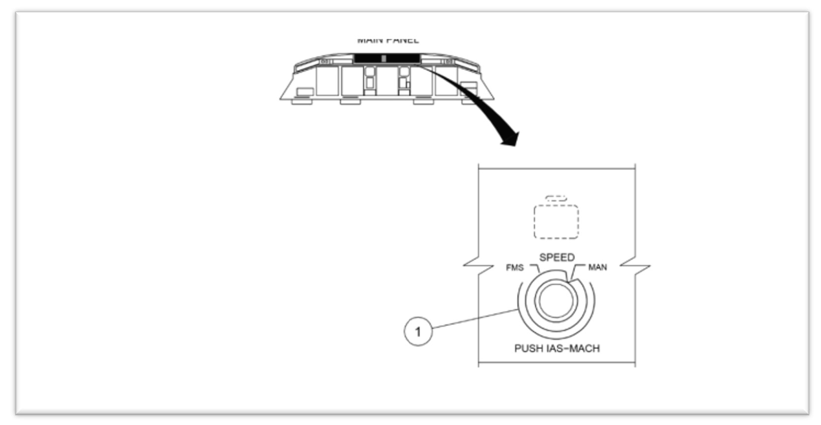
The flight crew had the option of selecting either of 2 speed management modes on the GP – FMS or manual mode (Figure 1).
Figure 1: E190 speed selector knob on guidance panel
Source: Alliance interim safety report
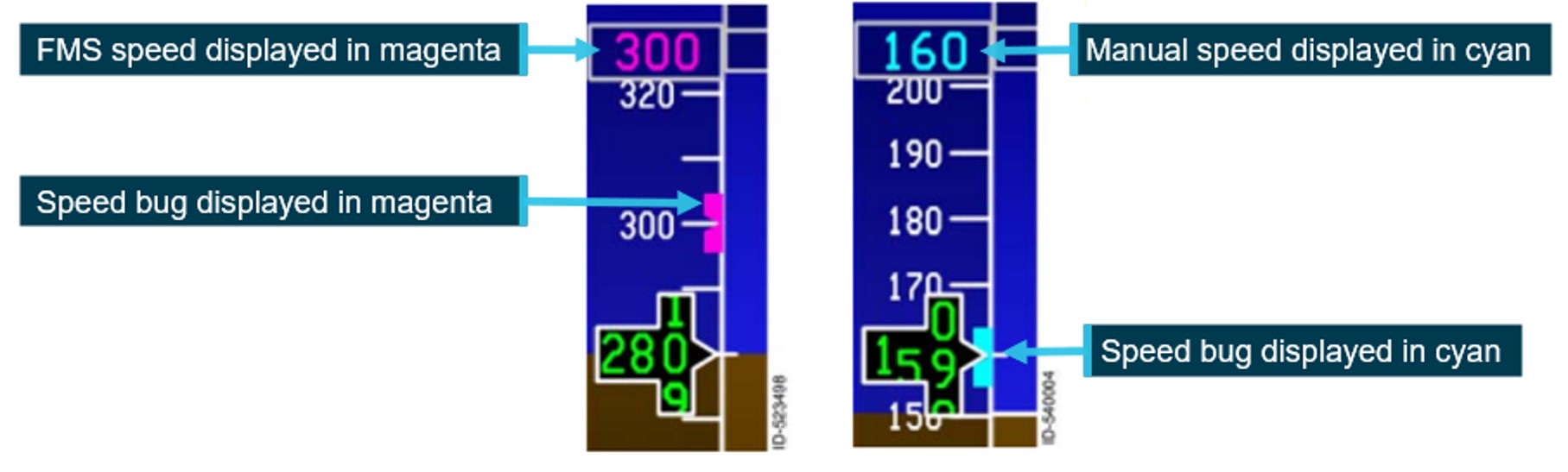
In FMS mode, the airspeed selection was managed by the FMS. The airspeed was displayed on the PFD in magenta (Figure 2).
In manual mode, flight crew retained responsibility for airspeed control, by selecting the airspeed using the SPEED selector knob, which then displayed the selected airspeed on the PFD (Figure 2). This target speed was used by both the autothrottle and the autopilot. A manual selected airspeed was displayed on the PFD in cyan.
Figure 2: FMS and manual speed displays
Example of speed tape showing the different speed modes. FMS mode on the left and manual mode on the right. Source: Honeywell, annotated by the ATSB
Prior to take-off, the pilot entered the required V speeds[9] from the multifunction control display unit (MCDU). These were then displayed on the lower portion of the speed tape.
The operator specified that if manual speed mode was selected for take-off:
when conducting a take-off in flap 1 to 3 configuration, the airspeed was to be set to final segment speed (VFS), which was the speed to be achieved during the final take-off segment, with landing gear up and flaps retracted
when conducting take-off in a flap 4 configuration, the airspeed should be set to 175 kt
when using noise abatement procedures, the airspeed should be set to V2 +10 kt.
The selection of speed mode was referenced in pre-flight, before-start and shutdown procedures (see the section titled Mode selection procedures).
Vertical modes
The autoflight control system (AFCS) has 11 modes to control the aircraft’s flight path. Two modes were relevant to this incident – take-off (TO) and vertical navigation flight level change (VFLCH).
In TO mode, the flight crew fly with reference to the flight director (FD). The flight crew set take‑of/go around (TOGA) power and then manually rotate the aircraft to the displayed pitch attitude on the FD to achieve the required airspeed.
When the mode was changed to a mode other than TO, the AFCS will start using the target airspeed as a reference. In VFLCH, the autothrottle holds the thrust lever at the set thrust value and the FD changes the pitch angle to maintain the airspeed at the target airspeed selected on the PFD. According to the operator’s standard operating procedures manual (SOPM), VFLCH is the preferred climb mode.
Flaps
The E190, has both flaps and slats. With the flap lever in position 4, the flaps extend to 20° and the slats to 25º. Moving the flap lever to position 3 moves the slats to 15º, with the flap position remaining unchanged.
With slats extended, the critical angle of attack (AOA)[10] is increased, enabling the aircraft to operate at a greater AOA. Conversely, once slats are retracted, the critical AOA decreases.
Flap retraction – F-Bug
The PFD shows the ideal flap selection speed using a symbol (green dot) on the speed tape. The flap retraction speed is shown using a magenta bug (F-bug). The flap manoeuvring speed is calculated based on the airplane weight and slat/flap setting and does not change with bank angle or turbulence.
The operator’s E190 aircraft operations manual (AOM) stated that:
During flap retraction, the next flap setting should be selected when the F-Bug is reached.
The F-Bug calculation is designed to meet minimum safe margins to VFE[11] and shaker speed. A minimum margin of 20% above the stall speed[12] is set for the next flap.
F-bug speeds calculated for the flight, provided by the manufacturer:
Flap lever
4
3
2
1
0
F-bug
154
164
174
184
-
Stall warning protection system
Overview
The E190 stall warning protection system (SWPS) is a 2-stage system that warns and protects the aircraft from aerodynamic stall conditions. The first stage warns the pilot of the impending stall by:
showing a low-speed awareness indication on the airspeed tape
showing a pitch limit indication on the attitude direction indicator on the primary flight display
activating the stick shaker motor on each control column results in each control column to shake (simulating the aircraft buffeting).
The second level is an AOA limiter protection system that limits the maximum AOA to a safe value below the predicted aerodynamic stall (preventing a stall).
Low-speed awareness system
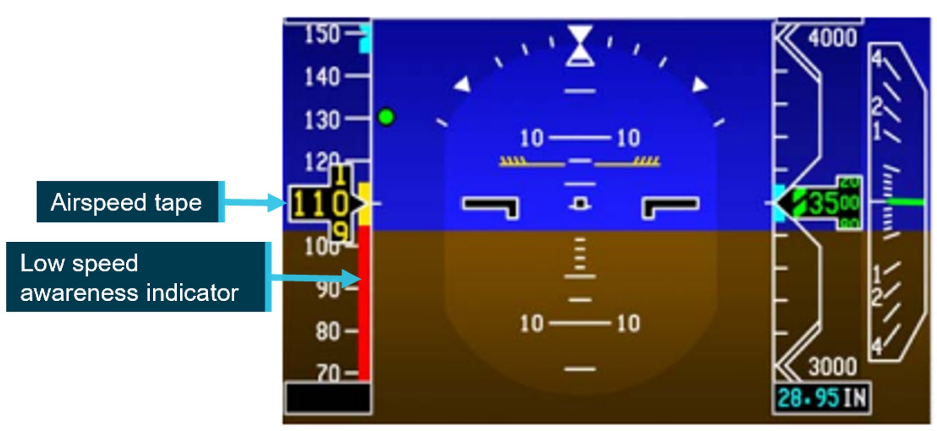
A low-speed awareness (LSA) indicator is displayed along the lower-right side of the airspeed tape (Figure 3Figure 3). LSA varies with the load factor[13] of the aircraft and the bar position is based on airspeed, aircraft configuration and AOA. The bar rises from the bottom of the tape to show both the calculated stall and stick shaker[14] speed (Vshaker) in 2 coloured ranges:
the amber range displays from Vshaker to 1.13 x stall speed
a stall occurs at the top of the red range, when the airspeed drops below Vshaker.
If the speed enters the red range, the stick shaker will activate, and an audible alarm will sound. The speed displayed on the PFD will also change colour to red reverse video.
Figure 3: Low speed awareness indicator
Source: Honeywell, annotated by the ATSB
Controller logic
While in TO mode with the speed control in manual, if the speed set is lower than V1, the controller logic automatically increases the speed to V1, after the ground‑to‑air transition.
Further, the aircraft manufacturer and avionics manufacturer advised that the controller logic ensures that the LSA indicator does not allow the selected speed to stay in the red range. If the manual speed selected on the guidance panel was in the amber band, the LSA automatically increased the speed to target the top of the amber band.
In this instance, the manual speed target initially increased to 125 kt after rotation and then, due to load effects during the climbing turn, the top of the amber band (and the target airspeed) further increased to 131 kt.
The aircraft manufacturer advised that the aircraft’s controller logic would always attempt to avoid unsafe conditions within a given envelope. The protective measures would not stop working unless the limit of conditions were met – in which case they would be announced to the crew by way of speed displayed in amber on the LSA indicator, the activation of pitch limit indicators (PLI) (see the section titled Pitch limit indicators) and eventually a stick shaker.
Autothrottle low speed protection
When the autothrottle was providing speed control, it would ensure both high and low speed envelope protection. The manual target speed was limited to the minimum maneuvering speed, flap/gear placard speed or the low speed awareness speed. The autothrottle lower speed limit was the greater of the manual speed target or 1.2 the stall speed. When flaps were extended, the autothrottle would maintain 1.2 x stall speed.
However, when the system was in VFLCH mode, airspeed was controlled by the elevator, with the autothrottle targeting a fixed thrust setting and therefore not providing low speed protection. The FD pitch controller providing speed control did not contain low speed protection and targeted the selected target speed on the guidance panel.
Pitch limit indicators
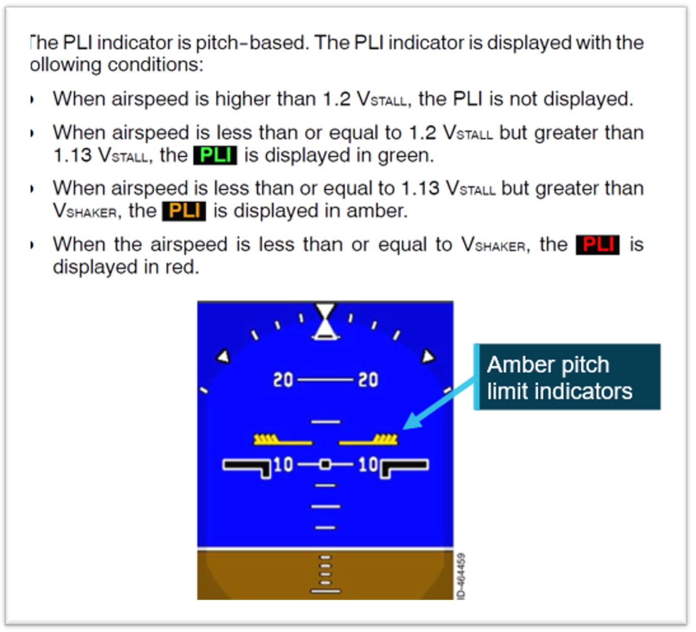
The aircraft’s SWPS computed a pitch limit indicator (PLI). This was a ‘pitch-based indication of the margin (in degrees) between the stick shaker speed and the current airspeed’ (Figure 4). The PLI margin was calculated continuously and displayed on the PFD when the airspeed was less than 1.2 the stall speed.
Figure 4: Pitch limit indicators
Source: Honeywell, annotated by the ATSB
Operational information
Mode selection procedures
The aircraft manufacturer provided operators with an airplane operations manual (AOM) and standard operating procedures manual (SOPM).
Regarding the 2 documents, the aircraft manufacturer stated:
The intention of the AOM is to gather all the information related to the operation of the aircraft, while the Embraer SOP is generated to provide operational guidance (it is ‘our way’ of operating the aircraft).
Both can be used by the operator, who must produce their own procedures (usually, dealing with mixed fleets) … Thus, operators can create their SOP using our SOP as a starting point and can add or change some points using information from the AOM, or even mix some internal operational information, but the final set must be approved.
This is a flexibility that operators can take advantage of. However, in all cases, following the instructions of the Embraer AOM/SOP entirely, as well as the operator’s SOP, should not lead to undesirable conditions.
As long as the Embraer AOM or SOP is followed in full, no undesirable results will occur.
Manufacturer’s airplane operations manual
The manufacturer’s AOM Before start procedures called for the speed selector knob to be set to manual:
SPEED Knob............................................. MAN
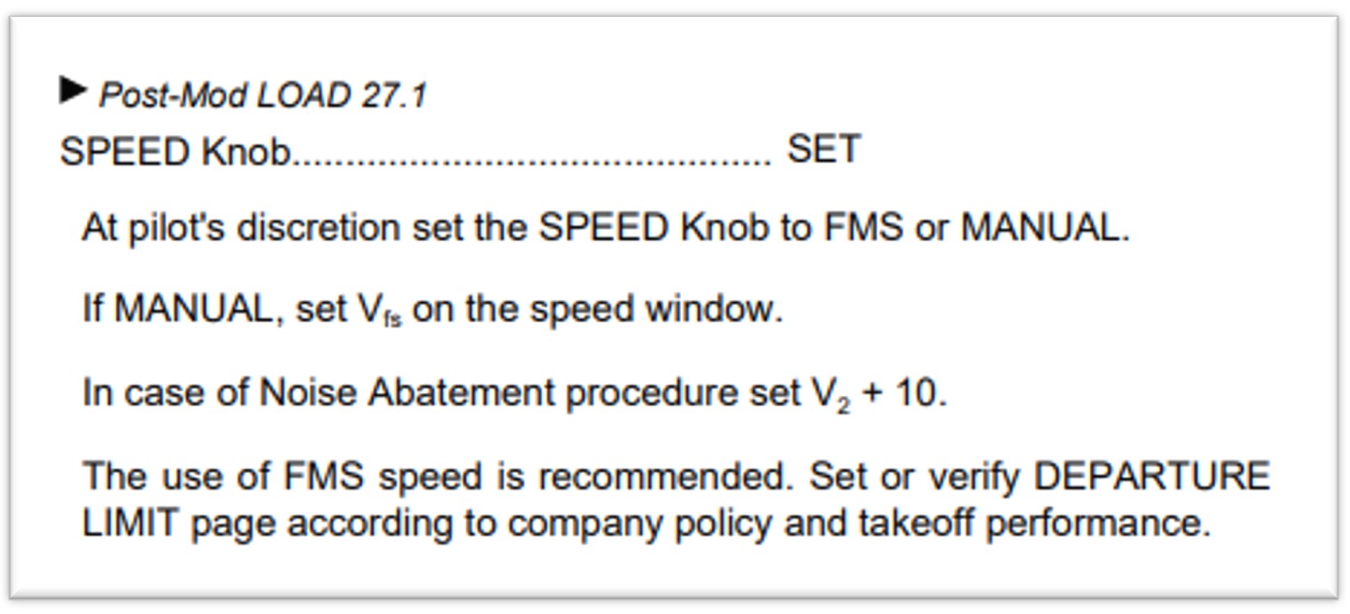
Subsequently, the Shortly before startup procedures (Figure 5), called for the speed selector knob to be set at pilot discretion, with FMS recommended for Load 27 aircraft (including VH-UYI).
Figure 5: Shortly before startup procedures
Source: Embraer E190 airplane operations manual – normal procedures
Manufacturer’s standard operating procedures manual (SOPM)
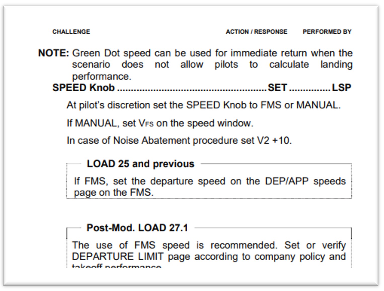
Unlike the AOM, the SOPM did not have a requirement to set the speed selector knob to manual in the Before start procedures. The first reference to speed selector knob was in the Shortly before start procedures (Figure 6), where the left seat pilot (LSP) was required to set it at pilot’s discretion (with FMS speed recommended).
Figure 6: Shortly before start procedures
Source: Embraer E190 standard operating procedures manual – normal procedures
The manufacturer advised that:
There is no need to set the speed to manual in the pre-flight, because once the necessary data is filled in the FMS (via MCDU), the correct speed target will be automatically set, provided that the selector is in FMS SPEEDS.
The step of bringing it [speed] to manual, mentioned in the AOM, is not included in our SOP, and is not taught in our [original equipment manufacturer] OEM training, as the SOP procedures are followed instead.
Operator’s standard operating procedures manual (SOPM)
The operator advised that:
As is industry practice, Alliance Airlines adapted the manufactures E190 manual suite, including the E190 AOM and SOPM to develop SOPs that are suitable for our operation. Like other airlines, Alliance Airlines continuously monitors manufacturers recommendations and conducts ongoing reviews of our SOPs to ensure they are fit for purpose, compliant with regulations and follow industry best practice.
The operator split the Before start procedures between Pre-flight and Before start procedures
Pre-flight procedures
Due to the alignment with the manufacturer’s AOM, the operator’s Pre-flight procedures required the LSP to set the speed selector knob to manual mode.
The operator understood this step was required to clear any previously set FMS speeds. However, the avionics manufacturer advised that:
From the FMS side (Load 27), there is not a mandatory requirement to set it [speed knob] to manual and it does not have logic to reset the previous autospeed target by setting the speed selector to manual. Rather, the previous flight information is cleared 2 minutes after landing.
Although not documented in their SOPM, the operator advised that it was customary for the right seat pilot (RSP) to switch the speed selector knob to manual during a Shutdown flow, which was intended as an additional protection to ensure that the speed selector knob was selected to manual.
Before start procedures
As part of the Before start flow, the operator’s procedures required the LSP to set the speed selector knob to either manual or FMS, and for aircraft running load 27, FMS mode was the recommended mode. This was not required to be stated out loud, nor challenged by the right seat pilot.
The Before start flow was termed ‘TOGA TARA SPEED’ as follows:
The LSP should perform the following actions
• Press the TO/GA [take-off/go-around] button to arm the Flight Director for take-off mode.
• Select TA/RA on the transponder.
• At the pilot’s discretion set the SPEED Knob to FMS or MANUAL. If MANUAL, set VFS on the speed window for Flap 1–3 take-off or 175kts for Flap 4 take-off.
• If required, select NAV for a LNAV [lateral navigation mode] departure.
The crew then performed the Before start procedures, which again called for the speed selector knob to be set, with FMS mode recommended.
The engines were then started, and the relevant checklists completed.
The operator’s procedures subsequently included:
As late as practical approaching the take-off point, the PF for the sector should complete a take-off brief review in accordance with Alliance Airlines [Operations Policy and Procedures Manual] OPPM. This should also include items such as flap setting, runway and intersection, RNP status, assigned altitude setting as applicable and changed weather conditions.
However, the OPPM referred to did not include any information regarding speed settings.
The manufacturer stated that:
while the Embraer [standard operating procedures] SOP did not explicitly mention speeds, it was expected that operators' SOPs cover speeds and cross-check the parameters, which are: V1, VR, V2, VFS values and bugs on the speed tape and V2 magenta or VFS blue on the speed target. In this way, the take-off briefing is a second opportunity to verify the correct value set.
Take-off procedures
The operator’s Take-off procedures stated:
FMA modes are not called until 400 ft to allow the PM to call any abnormal conditions as well as to reduce distraction during the take-off roll.
The manufacturer advised that as the take-off is a critical phase of flight:
Embraer’s SOPs recommend that selections and other heads-down tasks be avoided during this phase. The PF is flying the aircraft even while on the ground, and should be concentrating on maintaining directional control, cross-checking the instruments and alerting for any abnormal conditions. While the PM should be monitoring flight parameters (speed), engine parameters, the engine indicating and crew alerting system (EICAS) and monitoring the actions of the PF. Furthermore, the pilot in command is also monitoring for any abnormalities to make the Go/No-Go decision until V1 is reached.
Speed mode training
The operator advised that, although it was not documented in their training manual:
Thorough simulator type rating training is conducted to consolidate understanding…
the general practice of confirming a selection using the PFD/ND [navigation display], rather than the position of a physical switch/lever, is best practice and a key principle of operating advanced aircraft. This philosophy is integrated into the Alliance E190 Type Rating program, with a strong emphasis on correct technique starting during the ground school phase.
during line operations (and training), the before start procedures (scans), cover the requirement for confirmation that either cyan or magenta, are as anticipated, and that the calculated speeds are accurate.
The captain reported that manual speed would have been displayed in cyan, which should have stood out during the scans. They advised they had not used manual speed mode for take-off other than in the simulator during type rating training.
The FO also reported not having used manual mode previously and had not specifically been told to check for FMS/manual speed displaying in cyan or magenta in the speed window.
The manufacturer did not provide a specific training syllabus, rather expected the aircraft operator to develop the training manual. Therefore, type rating training for the aircraft was operator-specific.
Review of other E190 operator’s procedures
The ATSB conducted a review of another E190 operator’s procedures and found that they did not have a requirement for the speed mode to be set to manual during pre-flight, before start procedures or shut down procedures. That is, the speed mode remained in FMS speed throughout all phases of flight.
In addition, the operator had introduced into their SOPM, a verbal check of speed settings (FMS or Manual) as part of their FMS performance review prior to the flight.
Flight crew roles
The manufacturer established areas in the cockpit that were placed under the responsibility of a specific flight crewmember. Ground operations are divided between the left seat pilot (LSP) and the right seat pilot (RSP) while in-flight operations are divided between pilot flying (PF) and pilot monitoring (PM).
Regarding roles and responsibilities, the operator’s manual stated that:
The PF is responsible for controlling the vertical flight path and horizontal flight path and for energy management by either:
• supervising the auto pilot vertical and lateral modes through awareness of modes being armed or engaged, mode changes and of selected mode targets; or
• hand flying the aircraft, with or without flight director guidance.
The PNF [pilot not flying – same concept as PM] is responsible for:
• systems related monitoring
• monitoring tasks
• performing the actions requested by the PF.
The manufacturer manuals stated that when the aircraft does not perform as expected, the autopilot must be disconnected and manual flight promptly established. The manufacturer further advised it is ‘primary airmanship to monitor airspeed during every phase of flight, especially during take-off and initial climb’.
Pre-departure delays
Prior to departure, there were multiple irregularities involving ground handling, dispatch and loading sheets, passenger boarding and catering that required the captain’s attention. These included:
final loading sheet with a 2-tonne discrepancy from initial loading sheet
flight plan issued for Extended-range Twin-engine Operational Performance Standards (ETOPS) when not an ETOPS flight
final paperwork approximately 50 pages instead of 3–4 pages of relevant information
HF radio failure – requiring extra fuel to hold under 24,500 ft until ATC (Brisbane Centre) could be contacted
requirement to leave the bay due to incoming company aircraft.
Resolution of these issues resulted in the aircraft pushing back 30 minutes later than scheduled and the captain reportedly feeling mentally drained by the time they entered the cockpit. Additional delays due to other traffic, a closed taxiway and a displaced runway threshold resulted in the aircraft departing a further 30 minutes after pushback.
Recorded data
Quick access recorder data
Flight data from the aircraft’s quick access recorder (QAR) for the incident flight and the previous flight was analysed by the ATSB and the aircraft manufacturer.
The data showed that the speed selector knob had been selected to manual after touchdown on the previous flight.
QAR data confirmed that TOGA power was set and LNAV was armed, which were both items on the Before-start ‘TOGA TARA SPEED’ flow, indicating that part of the captain’s flow was conducted. TA/RA, another required item on the flow, was not a recorded parameter.
QAR data also confirmed that the captain was using the push to talk button as the aircraft’s speed decreased.
Stall speed, the low speed awareness (LSA) indicator and the pitch limit indicators (PLI’s) were not recorded by the QAR, however, the manufacturer provided the ATSB with calculations based off the QAR data.
They advised that prior to the flap lever retraction from 4 to 3, the top of the amber band on the LSA was 124.5 kt. When the slats retracted, 20 kts prior to the target speed (F-bug), the upper value of the amber LSA indicator[15] increased to 135.1 kt.
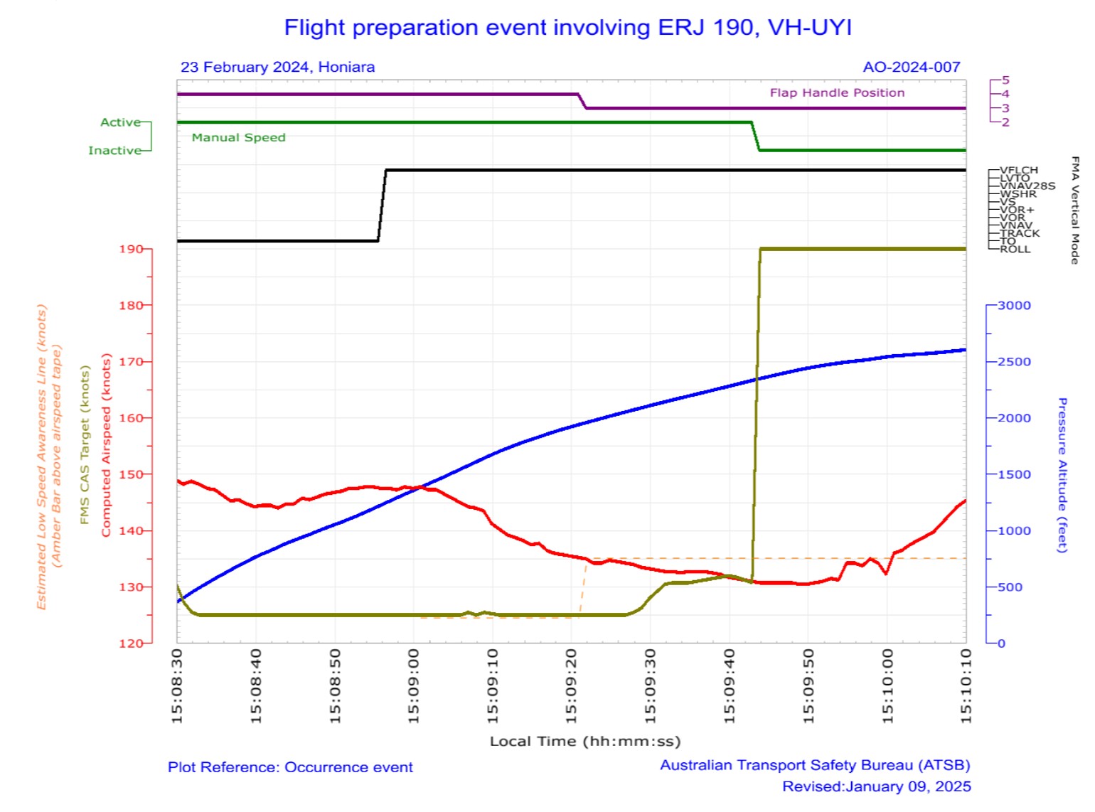
Figure 7: QAR data during initial climb
Source: ATSB
The data showed that once VFLCH was engaged, the airspeed (red line) reduced towards the FMS target speed (green line) at 125 kt. When the flap lever was retracted (purple line), the low speed awareness indicator increased to approximately 135.1 kt (dotted orange line), which was above the current airspeed of 134 kt. The PLIs would have been displayed on the PFD at this stage. The target speed then increased when the speed mode was selected to FMS.
Similar occurrences
As part of the operator’s internal safety investigation into this incident, a review of QAR data was conducted on flights operated in manual speed. From January 2022–July 2024, 254 flights were identified where manual speed setting was used. In 112 of those (including this incident), the flight crew had manual speed selected with no associated target speed set (80 kt).
In 76 of these 112 events, the QAR data showed that flight crew adjusted the speed mode selector to FMS during the take-off run and departed in FMS mode.
The operator advised that a review of the last 50 events where speed had not been set correctly, 38 individual captains were involved, operating from a range of different bases throughout the operator’s network.
Safety analysis
Introduction
During the pre-flight checks, undetected by either flight crew member, the captain unintentionally omitted to select the speed selector knob to flight management system (FMS), and the aircraft departed in manual mode without a target speed set. After take-off, with the airspeed at about 144 kt, vertical flight level change (VFLCH) mode engaged in the FMS, resulting in the flight director targeting the airspeed displayed on the primary flight display, of 125 kt. The aircraft then decelerated while in a banked turn with flap extended. The captain responded by retracting one stage of flap, resulting in a low-speed state. The flight crew then identified and corrected the speed mode selection. The stick shaker did not activate.
This analysis will discuss the flight crew’s actions in setting and monitoring modes and speeds, and flap retraction. The contribution of training and differences between the manufacturer’s and operator’s documentation will also be examined. Finally, other similar occurrences by Alliance Airlines flight crews and their responses will be examined.
Speed mode selection
Recorded flight data showed that the speed selector knob had been set to manual, as per the operator’s procedure for the copilot’s flow at shutdown, following the previous flight and the Pre‑flight procedures. It also showed the selector was not switched to FMS mode, as per the captain’s intention in the Before start procedures. Neither flight crewmember detected the speed selector knob in manual or that the speed colour on the primary flight display (PFD) was cyan (compared to the expected magenta) in the before start scans or during the take-off brief review.
After the aircraft rotated, the controller logic automatically increased the target speed to V1, which was 125 kt. However, at that time, as the aircraft was in take-off (TO) mode, the target speed was not affected, as the pilot flying was following flight director TO mode pitch guidance, and the system was targeting the desired V2 plus 10 kt (about 144 kt) for the take-off, and climb was maintained as expected.
Passing 1,200 ft, vertical flight level change (VFLCH) mode engaged. At this time, the flight director (FD) began to target the selected airspeed (125 kt) by increasing the pitch of the aircraft, and the airspeed gradually began to decrease.
Contributing factor
During the Before start procedure, the captain unintentionally left the speed selector knob in manual mode instead of flight management system mode, with no manual speed set. The manual speed mode selection was not detected by either flight crewmember, resulting in the aircraft decelerating after vertical flight level change mode was engaged.
Not monitoring speed
During the initial climb in non‑controlled airspace, the captain was making the required departure call, and monitoring traffic and weather.
As the aircraft entered a 25° bank turn to comply with the standard instrument departure (SID), the airspeed further decreased. The speed reduction and increased pitch was not detected by the PF, which may have been due to anticipating a slower climb in flap 4 configuration and a banked turn.
Contributing factor
While the captain was monitoring traffic, weather and making a radio broadcast, the first officer was not effectively monitoring the airspeed and, as a result, did not initially detect the aircraft decelerating.
Flap retraction
Although the aircraft was slower and pitched higher than usual at that time, it was operating at a safe speed. Manufacturer calculations showed that the top of the LSA amber band was at approximately 125 kt during this time and the airspeed was decelerating through 134 kt.
However, when the PM detected that the aircraft was not accelerating, they retracted flap from 4 to 3 (slat retraction) to reduce drag. The manufacturer’s calculations showed that this resulted in the upper value of the amber range on the LSA indicator increasing to about 135 kt. When slats were retracted, the airspeed was around 134 kt, therefore within the amber band, before further reducing to 131 kt. During that time, the pitch limit indicators (PLI’s) would have activated and been displayed on the primary flight display.
The manufacturer required that if the aircraft was not performing as expected, the flight crew were required to disconnect the autopilot and manually fly the aircraft.
Contributing factor
Having assessed that the low airspeed was due to excessive drag, the captain retracted one stage of flap while below the minimum flap target speed, resulting in the aircraft entering a low-speed state.
Manufacturer’s airplane operations manual
The manufacturer’s airplane operations manual (AOM) was inconsistent with their standard operating procedures manual (SOPM). Specifically, it required the speed selector knob to initially be set to ‘manual’ in the Before start procedures, which was not an SOPM requirement.
While the use of manual speed was valid, it was unnecessary for the AOM to require initial setting of manual speed in the Before start procedures, as the selection of speed mode was later made in the Shortly before start procedures. It also increased the risk of flight crews not switching the speed selector knob back to the commonly-used FMS speed prior to departure.
Contributing factor
Embraer's airplane operations manual was inconsistent with its standard operating procedures manual in relation to speed mode selection. This increased the risk of flight crews departing with the manual speed mode unintentionally selected. (Safety issue)
Operator’s procedures
While the manufacturer’s AOM was inconsistent with their SOPM, the operator advised that it had reviewed both documents when developing their own SOPM.
Despite manual speed mode rarely being used, the operator included a requirement for it to be initially set to manual, and then selected to FMS prior to take-off, in line with the AOM. The inclusion of this requirement in its SOPM may have also been influenced by an incorrect belief that it was required to clear previous speeds entered in the flight management system (FMS). In that context, while well intentioned, it increased the risk of the aircraft departing with the incorrect speed mode selected.
In addition, the operator also included an undocumented right seat pilot flow at shut down to switch the speed selector knob to manual. This step was not in accordance with the aircraft manufacturer’s AOM or SOPM and similarly increased the risk of the incorrect speed being selected for take-off.
Contributing factor
Consistent with Embraer’s airplane operations manual, the Alliance Airline's pre-flight procedure required flight crew to unnecessarily initially set the speed knob to ‘manual’. That increased the risk of the aircraft departing with the incorrect speed mode selected. (Safety issue)
Other factor that increased risk
Alliance Airlines’ right seat pilot shutdown flow was undocumented and not in accordance with the manufacturer’s guidance.
Training
While the operator stated that the training and line checks ensured that crews were checking that the speeds were displayed in cyan or magenta as expected, these requirements were not documented in the training manual. Additionally, the first officer (FO) reported never having been told to specifically look at the colour (magenta/cyan) of the speed display as part of their scans.
The captain did not ensure the target speed was depicted in the expected colour. They had only conducted a take‑off with the speed selector knob in manual mode once, as part of their initial training in the simulator.
Unlike standard operating procedures, type rating training was not stipulated by the manufacturer, instead was developed by each aircraft operator. The manufacturer was unaware of any other operator having had similar events. Given there were 112 occurrences where the operator’s flight crew had not correctly set the speed selector knob, nor detected the incorrect speed selector knob selection and the speed colour in cyan in the display prior to the take-off run, it is likely that the operator’s training and line checks were not adequate in ensuring flight crew were completing their scans as per the manufacturer’s and operator’s requirements.
Contributing factor
Likely due to a training deficiency, Alliance Airlines flight crews' conduct of the Before start procedures and Pre-take-off brief review were not being performed effectively to ensure the speed selector knob was correctly set and checked, which increased the risk of a low-speed event after take-off. (Safety issue)
Similar incidents
A review of past occurrences identified 112 incidents (including this incident) in the preceding 30 months where flight crews had unintentionally not set the speed selector knob to FMS. In 76 of these events it was identified that the flight crew had adjusted the speed selector knob during the take-off run, a critical stage of flight. The manufacturer’s SOPM recommended that mode selections and other heads-down tasks be avoided during critical phases of flight. To mitigate that risk, the manufacturer’s and operator’s SOPM required that correction to the speed mode selection should be made when passing 400 ft on climb.
Other factor that increased risk
Alliance Airlines flight crews were regularly changing the speed selector knob setting during the take‑off run. This was contrary to Embraer's guidance, and Alliance Airlines’ own standard operating procedures manual. This increased the risk of distraction during a critical phase of flight. (Safety issue)
Findings
ATSB investigation report findings focus on safety factors (that is, events and conditions that increase risk). Safety factors include ‘contributing factors’ and ‘other factors that increased risk’ (that is, factors that did not meet the definition of a contributing factor for this occurrence but were still considered important to include in the report for the purpose of increasing awareness and enhancing safety). In addition ‘other findings’ may be included to provide important information about topics other than safety factors.
Safety issues are highlighted in bold to emphasise their importance. A safety issue is a safety factor that (a) can reasonably be regarded as having the potential to adversely affect the safety of future operations, and (b) is a characteristic of an organisation or a system, rather than a characteristic of a specific individual, or characteristic of an operating environment at a specific point in time.
These findings should not be read as apportioning blame or liability to any particular organisation or individual.
From the evidence available, the following findings are made with respect to the incorrect configuration involving Embraer E190, VH-UYI at Honiara Airport, Solomon Islands on 23 February 2024:
Contributing factors
During the Before start procedure, the captain unintentionally left the speed selector knob in manual mode instead of flight management system mode, with no manual speed set. The manual speed mode selection was not detected by either flight crewmember, resulting in the aircraft decelerating after vertical flight level change mode was engaged.
While the captain was monitoring traffic, weather and making a radio broadcast, the first officer was not effectively monitoring the airspeed and, as a result, did not initially detect the aircraft decelerating.
Having assessed that the low airspeed was due to excessive drag, the captain retracted one stage of flap while below the minimum flap target speed, resulting in the aircraft entering a low‑speed state.
Embraer's airplane operations manual was inconsistent with its standard operating procedures manual in relation to speed mode selection. This increased the risk of flight crews departing with the manual speed mode unintentionally selected. (Safety issue)
Consistent with Embraer’sairplane operations manual, the Alliance Airline's pre-flight procedure required flight crew to unnecessarily initially set the speed knob to ‘manual’. This increased the risk of the aircraft departing with the incorrect speed mode selected. (Safety issue)
Likely due to a training deficiency, Alliance Airlines flight crews' conduct of the Before start procedures and Pre-take-off brief review were not being performed effectively to ensure the speed selector knob was correctly set and checked, which increased the risk of a low-speed event after take-off. (Safety issue)
Other factors that increased risk
Alliance Airlines’ right seat pilot shutdown flow was undocumented and not in accordance with the manufacturer’s guidance.
Alliance Airlines flight crews were regularly changing the speed selector knob setting during the take‑off run. This was contrary to Embraer's guidance, and Alliance Airline’s own standard operating procedures manual. This increased the risk of distraction during a critical phase of flight. (Safety issue)
Safety issues and actions
Central to the ATSB’s investigation of transport safety matters is the early identification of safety issues. The ATSB expects relevant organisations will address all safety issues an investigation identifies.
Depending on the level of risk of a safety issue, the extent of corrective action taken by the relevant organisation(s), or the desirability of directing a broad safety message to the aviation industry, the ATSB may issue a formal safety recommendation or safety advisory notice as part of the final report.
All of the directly involved parties were provided with a draft report and invited to provide submissions. As part of that process, each organisation was asked to communicate what safety actions, if any, they had carried out or were planning to carry out in relation to each safety issue relevant to their organisation.
Descriptions of each safety issue, and any associated safety recommendations, are detailed below. Click the link to read the full safety issue description, including the issue status and any safety action/s taken. Safety issues and actions are updated on this website when safety issue owners provide further information concerning the implementation of safety action.
Safety issue description: Embraer's airplane operations manual was inconsistent with its standard operating procedures manual in relation to speed mode selection. This increased the risk of flight crews departing with the manual speed mode unintentionally selected.
Safety issue description: Consistent with Embraer’s airplane operations manual, the Alliance Airline's pre-flight procedure required flight crew to unnecessarily initially set the speed knob to ‘manual’. This increased the risk of the aircraft departing with the incorrect speed mode selected.
Multiple occurrences of the speed selector knob not being set correctly and flight crews not detecting the incorrect setting
Safety issue description: Likely due to a training deficiency, Alliance Airlines flight crews' conduct of the Before start procedures and Pre-take-off brief review were not being performed effectively to ensure the speed selector knob was correctly set and checked, which increased the risk of a low-speed event after take-off.
Multiple occurrences of speed selector knob being reset during a critical phase of flight
Safety issue description: Alliance Airlines flight crews were regularly changing the speed selector knob setting during the take‑off run. This was contrary to Embraer's guidance, and Alliance Airline’s own standard operating procedures manual. This increased the risk of distraction during a critical phase of flight.
Safety action not associated with an identified safety issue
Additional safety action by Alliance Airlines
In addition to the safety action taken to address the identified safety issues, Alliance Airlines:
Issued an article to flight crew highlighting that at the completion of the before start duties, the left seat pilot should apply the technique of selecting ‘TOGA, TARA, SPEED’, followed by confirmation of the relevant modes and settings on the primary flight display, prior to calling for the completion of the Before start checklist.
Advised that a dedicated training module will be incorporated into recurrent simulator cyclic training exercises commencing 1 January 2025. This module will include a review of this occurrence, its root cause, and a reinforced focus on correct procedures and techniques to prevent reoccurrences.
Advised that during recurrent line check events, there will be an added emphasis on reviewing and ensuring adherence to the correct procedures and techniques.
The sources of information during the investigation included:
flight crew of the incident flight
Alliance Airlines
recorded data from the quick access recorder
Embraer
Honeywell
References
Alliance Airlines, ‘E190 standard operating procedures manual’, Issue 1.2, August 2023.
Embraer S.A., ‘170/175/190/195 Standard Operating Procedures Manual’, Revision 29, June 2024.
Embraer S.A., ‘Embraer E190 Airplane Operations Manual, Volume 1, AOM-1502-047, November 27 2020, Revision 5 – January 31, 2024
Honeywell, Primus Epic pilot’s guide – integrated avionics system for E190 Load 27, October 2023.
Regional Aviation Safety Group-Pan America ‘Mode Awareness and Energy State Management Aspects of Flight Deck Automation’, November 2022
Submissions
Under section 26 of the Transport Safety Investigation Act 2003, the ATSB may provide a draft report, on a confidential basis, to any person whom the ATSB considers appropriate. That section allows a person receiving a draft report to make submissions to the ATSB about the draft report.
A draft of this report was provided to the following directly involved parties:
flight crew of the incident flight
Alliance Airlines
Civil Aviation Safety Authority
Honeywell
Embraer
Brazilian Aeronautical Accidents Investigation and Prevention Center
United States National Transportation Safety Board
Submissions were received from:
the first officer of the incident flight
Alliance Airlines
Embraer
The submissions were reviewed and, where considered appropriate, the text of the report was amended accordingly.
Purpose of safety investigations
The objective of a safety investigation is to enhance transport safety. This is done through:
identifying safety issues and facilitating safety action to address those issues
providing information about occurrences and their associated safety factors to facilitate learning within the transport industry.
It is not a function of the ATSB to apportion blame or provide a means for determining liability. At the same time, an investigation report must include factual material of sufficient weight to support the analysis and findings. At all times the ATSB endeavours to balance the use of material that could imply adverse comment with the need to properly explain what happened, and why, in a fair and unbiased manner. The ATSB does not investigate for the purpose of taking administrative, regulatory or criminal action.
Terminology
An explanation of terminology used in ATSB investigation reports is available here. This includes terms such as occurrence, contributing factor, other factor that increased risk, and safety issue.
Publishing information
Released in accordance with section 25 of the Transport Safety Investigation Act 2003
Ownership of intellectual property rights in this publication
Unless otherwise noted, copyright (and any other intellectual property rights, if any) in this report publication is owned by the Commonwealth of Australia.
Creative Commons licence
With the exception of the Commonwealth Coat of Arms, ATSB logo, and photos and graphics in which a third party holds copyright, this report is licensed under a Creative Commons Attribution 4.0 International licence.
The CC BY 4.0 licence enables you to distribute, remix, adapt, and build upon our material in any medium or format, so long as attribution is given to the Australian Transport Safety Bureau.
Copyright in material obtained from other agencies, private individuals or organisations, belongs to those agencies, individuals or organisations. Where you wish to use their material, you will need to contact them directly.
[1]Pilot Flying (PF) and Pilot Monitoring (PM): procedurally assigned roles with specifically assigned duties at specific stages of a flight. The PF does most of the flying, except in defined circumstances, such as planning for descent, approach and landing. The PM carries out support duties and monitors the PF’s actions and the aircraft’s flight path.
[2]A flow is the basic methodology for running through system checks and setup of the aircraft in varying phases of flight. A flow is meant to be a muscle-memory way to set up the aircraft. Flows are memorised and seen as a quick way to run through all the important checks of an aircraft.
[3]Rotation: the positive, nose-up, movement of an aircraft about the lateral (pitch) axis immediately before becoming airborne.
[4]TOGA power: Take off/Go around power – During take-off, pressing the TO/GA switch or advancing the thrust levers to the TO/GA position will command the engines to increase their RPM to the calculated take-off power setting.
[5]V1: the critical engine failure speed or decision speed required for take‑off. Engine failure below V1 should result in a rejected take‑off; above this speed the take-off should be continued.
[6]V2: The minimum speed at which a transport category aircraft complies with those handling criteria associated with climb following an engine failure. V2 is the take-off safety speed and is normally obtained by factoring the stalling speed or minimum control (airborne) speed, whichever is the greater, to provide a safe margin.
[7]CTAF: VHF radio frequency allocated at an airport for pilots to self-announce their intentions and communicate with one another. It's a basic collision avoidance tool at uncontrolled (non-towered) airports.
[8]Flight information service: A service that provides pilots with advice and useful information such as: meteorological traffic information and aerodrome facilities or hazards.
[9]V speeds: take-off reference speeds or V speeds are provided by the manufacturer to assist pilots in determining when a rejected take off should be initiated, and when the aircraft can rotate, lift off and climb.
[10]Critical angle of attack: as the AOA increases, both lift and drag increase, however, above a wing’s critical AOA, the flow of air separates from the upper surface and backfills and eddies, which reduces lift and increases drag. This condition is a stall, which can lead to loss of control and an abrupt loss of altitude if the AOA is not reduced.
[11]VFE: maximum flap extended speed: the fastest speed at which an aircraft can fly safely with its flaps extended.
[12]Aerodynamic stall: occurs when airflow separates from the wing’s upper surface and becomes turbulent. A stall occurs at high angles of attack, typically 16° to 18°, and results in reduced lift.
[14]Stick shaker: a mechanical warning device that vibrates the aircraft’s control column when it approaches a stall.
[15]Amber band is not a recorded parameter on the QAR. Calculations of amber band values were made by the manufacturer based on the weight and configuration of the aircraft and was estimated to be 1.08 x red band. The calculated value does not consider the aircrafts pitch attitude, which may have induced an even higher LSA value.
Occurrence summary
Investigation number
AO-2024-007
Occurrence date
23/02/2024
Location
Near Honiara International Airport
State
International
Report release date
03/04/2025
Report status
Final
Investigation level
Defined
Investigation type
Occurrence Investigation
Investigation status
Completed
Mode of transport
Aviation
Aviation occurrence category
Incorrect configuration
Occurrence class
Incident
Highest injury level
None
Aircraft details
Manufacturer
Embraer-Empresa Brasileira De Aeronautica
Model
ERJ-190-100 IGW
Registration
VH-UYI
Serial number
19000053
Aircraft operator
Alliance Airlines Pty Limited
Sector
Jet
Operation type
Part 121 Air transport operations - larger aeroplanes
On 6 December 2023, an Airbus A380-842 aircraft, registered VH‑OQI and operated by Qantas Airways Limited, was undergoing a 3-day scheduled maintenance check at Los Angeles International Airport (LAX), United States.
On day one of the maintenance check, during a scheduled borescope inspection of the outboard left engine, a tool was left in the engine inlet. On the evening of 8 December, the aircraft was released to service and departed for Melbourne, Victoria.
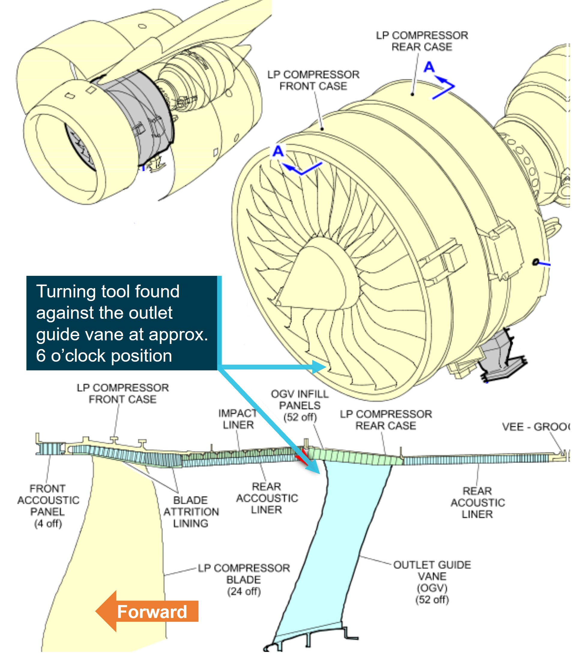
On 1 January 2024, the aircraft returned to the LAX maintenance facility for a 3-day scheduled maintenance check, where the missing tool was discovered in the outboard left engine low‑pressure compressor. The aircraft had flown 34 cycles totalling 293.74 hours with the tool in the outboard left engine.
What the ATSB found
The ATSB found that the tool was not located during the end of task foreign object inspections, which resulted in it remaining in the engine. The Qantas Engineering lost tool procedure was not commenced prior to the aircraft being released to service and the certifying engineer did not follow up on the lost tool, prior to releasing the aircraft to service.
What has been done as a result
On 2 January 2024, a Qantas Engineering internal incident report was raised with an immediate action to brief staff on the importance of ensuring that all tooling is returned and actioned by tool store personnel. A Qantas Engineering internal investigation was completed and on 4 March 2024, the executive manager for Qantas Engineering released an internal safety directive for immediate action requiring all Qantas Engineering employees to meet the company tooling control requirements without exception.
Safety message
Foreign object debris and damage poses a significant threat to the safe operation of aircraft. Regulations, procedures, and training have been put in place and refined to limit the risk of foreign object damage, especially from introduced objects during maintenance. As a result, the correct application of tool control is an important, fundamental, and necessary aspect of the maintenance process to mitigate any human errors that may arise.
The investigation
Decisions regarding the scope of an investigation are based on many factors, including the level of safety benefit likely to be obtained from an investigation and the associated resources required. For this occurrence, a limited-scope investigation was conducted in order to produce a short investigation report, and allow for greater industry awareness of findings that affect safety and potential learning opportunities.
The occurrence
On 6 December 2023, an Airbus A380-842 aircraft, registered VH-OQI and operated by Qantas Airways Limited, was inducted into the Qantas Engineering[1] Los Angeles Line Maintenance facility for scheduled maintenance at Los Angeles International Airport (LAX), United States.
The scheduled maintenance was to be carried out over 3 days and included a borescope inspection of the left outboard engine’s intermediate-pressure compressor. The borescope inspection was to be conducted on day one and was estimated to take approximately 6 hours. The aircraft was located outside of the maintenance hangar, on the hardstand, for the duration of the scheduled maintenance.
Day 1 – 6 December 2023
0700 local time
A licenced aircraft maintenance engineer (LAME 1) assigned 2 aircraft maintenance engineers (AME 1 and AME 2) to the engine borescope inspection task. A support engineer was also assigned to assist AME 1 and AME 2. AME 2 and the support engineer were both unfamiliar with the borescope task and were provided guidance by AME 1.
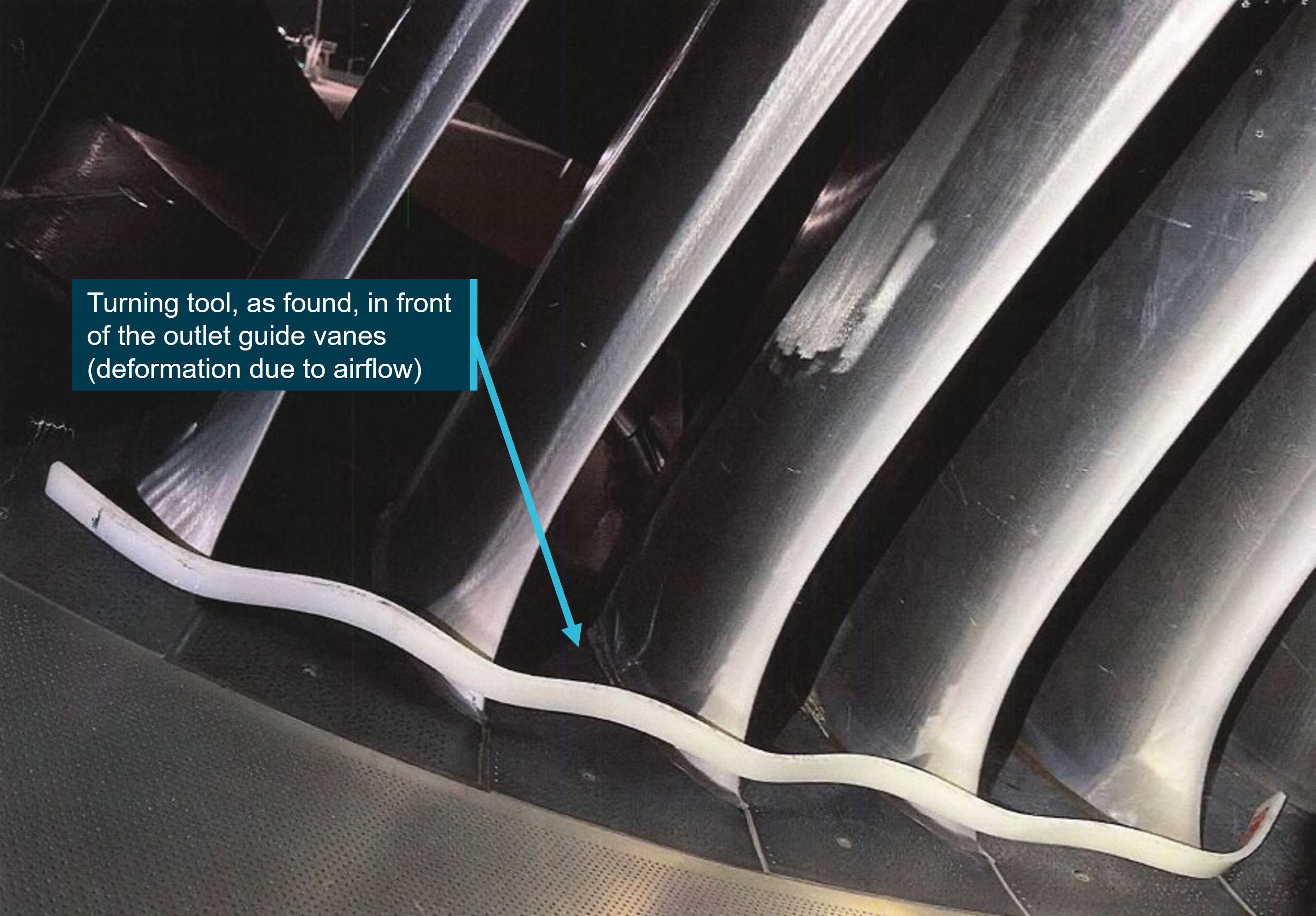
AME 1 and AME 2 collected the required managed tooling[2] from the hangar tool store[3], which included a 1.25 m long by 2.5 cm wide nylon rod, known as a turning tool[4] (Figure 1). The tooling was signed out by AME 1. The engineers placed access stands around the left outboard engine and commenced the task. The support engineer entered the engine inlet via the access stand and rotated the engine’s intermediate-pressure compressor, as required, using the turning tool. AME 1 and AME 2 remained underneath the engine, operating the borescope.
1300
AME 1 left work early for a medical appointment and then proceeded onto 3 rostered days off. The borescope task was only partially completed at this time and the turning tool remained assigned to AME 1.
After the departure of AME 1, AME 2 asked LAME 1 if the tools used on the borescope task required returning to the tool store. LAME 1 advised AME 2 to leave the tools with the aircraft as the afternoon shift, commencing at 1500, would complete the remainder of the task. AME 2 and the support engineer were then reassigned onto other tasks by LAME 1.
1500
The hangar tool store personnel ran a scheduled daily tooling report, [5] which identified that the turning tool was assigned to AME 1 and had not been returned.
Due to the borescope task being unfinished, LAME 1 decided to remain at work until the task was completed and certified in the aircraft’s computer‑based maintenance log (Maintenix).[6]
The afternoon shift, which consisted of 2 aircraft maintenance engineers (AME 3 and AME 4), commenced the remaining steps of the borescope task. AME 3 was experienced in the use of the borescope procedure and AME 4 had not conducted the procedure before.
The support engineer briefly returned to the task and provided guidance to AME 4 on the use of the turning tool prior to departing work for 3 rostered days off. AME 3 operated the borescope and AME 4 operated the turning tool.
AME 3 completed the inspection operating the borescope and asked AME 4 if they wanted to view the images prior to reinstalling the borescope access plugs on the engine. AME 4 left the turning tool in the inlet, as they believed it would be used again later, and proceeded out of the inlet down to the ground to view the borescope images. Neither AME 3 nor AME 4 re‑entered the engine inlet for the remainder of the shift.
1700
Tool store personnel emailed the scheduled daily tooling report, which was run at 1500, to all LAX service engineers, LAMEs, managers, and tooling personnel.
LAME 1 requested AME 2, the only AME remaining at work from the initial borescope tasking, to return the tooling used for the borescope task to the hangar tool store. AME 2 proceeded up to the inlet cowl to visually inspect that all tools were removed. AME 2 identified that an inlet cowling protective mat was still on an access stand. AME 2 removed the mat and conducted a brief visual inspection of the inlet to ensure no foreign objects remained. AME 2 did not use a torch and did not observe the turning tool.
The borescope equipment was returned to the hangar tool store and AME 2 then left work for the day. AME 2 was unaware that the turning tool was still in the low-pressure compressor case.
1830
LAME 1 conducted the first inspection[8] of the completed borescope task, and also conducted a foreign object debris check of the inlet using a torch but did not detect the turning tool. LAME 1 then certified the required tasks in Maintenix prior to proceeding on to 3 rostered days off, unaware that the turning tool had not been returned.
2100
Another licenced aircraft maintenance engineer, LAME 2, conducted the required second independent inspection.[9] LAME 2 inspected the security of the engine borescope access plugs and the engine lower area. They did not conduct an inspection of the inlet cowl.
2130
A third LAME, LAME 3, who was not involved in the task, while performing end-of-shift task closure duties, became aware of the missing turning tool identified in the tooling report. As the turning tool was assigned to AME 1, who was no longer at work, LAME 3 contacted AME 1 who advised that they had finished work at 1300 and that the turning tool was still in use at that time. LAME 3 then informed tool store personnel that the turning tool was still in use by the second shift when the daily tooling report had been run. LAME 3 took no further action.
Day 2 – 7 December 2023
1500
Tool store personnel conducted the daily scheduled tooling report. The report identified that the turning tool was still unaccounted for. The tooling report was not emailed to LAX service engineers, LAMEs, managers, or tooling personnel at this time.
Day 3 – 8 December 2023
1500
The hangar tool store personnel conducted the daily scheduled tooling report, which identified that the turning tool was still unaccounted for.
1840
Tool store personnel emailed the tooling report to all LAX service engineers, LAMEs, managers, and tooling personnel to remind them of the missing turning tool, noting that the aircraft was scheduled to depart at 2235 that night.
1845
The operations manager sent an email to the service engineer, who was certifying the Certificate of Release to Service (CRS)[10] for VH-OQI, reminding them that if the turning tool was still unaccounted for, to ensure that the Qantas Engineering lost tool procedure was carried out prior to aircraft departure (see Context section titled Lost toolprocedure).
2012
The service engineer, aware that the tool had been missing since 6 December and believing that the tool could not be still fitted to the aircraft, replied to the email from the operations manager and the on-duty tool store personnel acknowledging that VH-OQI was leaving at 2235 but also noted that the tool had been missing since 6 December 2023. The service engineer did not view the tooling report and continued with their certification of the CRS for VH-OQI (see the section titled Service engineer comments).
2336
VH-OQI departed LAX for Melbourne, Victoria.
10 December 2023
0700
LAME 1 returned to work after 3 rostered days off and was made aware of the missing turning tool. LAME 1 conducted a search of stores, engine stands, the hardstand (where VH-OQI’s maintenance was conducted) and the hangar, for the missing turning tool. The turning tool was not located.
1700
LAME 1 raised a missing tool report in Maintenix against VH-OQI. Although, the required follow-up process was not commenced and the associated administrative task, UTL-1, was not raised (see the Context section titled Lost tool procedure).
11 December 2023
0758
VH-OQI returned to LAX from Melbourne, on a scheduled passenger flight, but was not inducted into maintenance. The aircraft was not searched for the missing turning tool.
The aircraft returned to LAX on 19 December and again on 28 December. No scheduled maintenance was conducted at either time.
27 December 2023
Qantas engineers in Sydney, Australia, requested that Sydney tool store personnel remove the missing tool report against VH-OQI as it was affecting the issue of a CRS.
28 December 2023
1424
Sydney tool store personnel changed the status of the turning tool in Maintenix to ‘Ready for Issue’. They then sent an email to LAX tool store personnel requesting to change the status of the tool in the LAX tool store to ‘Quarantined’.
1530
LAX tool store personnel set the missing tool to ‘Quarantined’ and created a Maintenix task UTL‑2. As noted above, UTL-1 was not created in Maintenix, as procedurally required, after the missing tool report was raised on 10 December (see the Context section titled Lost tool procedure).
1 January 2024
VH-OQI returned to LAX on 1 January 2024, for a fourth time since the tool was reported missing and was inducted into scheduled maintenance. This scheduled maintenance included a detailed inspection of the low-pressure compressor blades on all 4 engines. During this inspection, the engineers located the missing turning tool in the outboard left engine in the low-pressure compressor and in front of the outlet guide vanes (Figure 1). The turning tool was removed from the engine and returned to the hangar tool store where it was physically placed in quarantine.[11]
Figure 1: Location of the turning tool as found in front of the low-pressure compressor outlet guide vanes
Source: Qantas Airways Limited, annotated by the ATSB
2 January 2024
1420
LAX tool store personnel closed UTL-2 in Maintenix.
Context
Borescope task
The intermediate-pressure compressor inspection task is a routine maintenance procedure in which the condition of the internal components of the engine are visually inspected and recorded using a portable borescope. The engine casing has a series of removable access ports known as borescope access blanking plugs. Once removed, these plugs allow an engineer to insert a borescope camera into the internals of the engine while a second engineer reaches between the low-pressure compressor blades and rotates the intermediate‑pressure compressor with the turning tool. This allows the borescope operator to inspect the rotating components of the engine as they pass by the borescope camera lens.
One of the final procedural steps of the intermediate-pressure compressor borescope inspection is to remove all inspection equipment from the engine.
Turning tool location
The turning tool was found behind the rotating low-pressure compressor blades, in approximately the 6 o’clock position (Figure 1 and Figure 2). It had been deformed by high energy airflow around the low-pressure compressor outlet guide vanes (non-rotating). There was no damage observed to any engine components.
Figure 2: Schematic of the Rolls Royce Trent 972-84 engine identifying the location of the turning tool
Source: Qantas Airways Limited, annotated by the ATSB
Tool issue and control
To facilitate turnaround times, Qantas, like other operators of large, complex aircraft, ran around‑the‑clock maintenance facilities, with teams of engineers working shifts. A single task, such as the borescope task, can take multiple workers and shifts to complete, and required specific tools for the duration. As no personal tools were used in the Qantas Engineering Los Angeles Line Maintenance facility, all tooling was kept in a hangar tool store and was issued to individual maintenance engineers for tasks.
Procedures to control these tools were in place and designed to track where the tool was, what aircraft it was being used on, and who was using it. This was from the time it was issued until it was returned. Any tools then unaccounted for, became ‘lost tools’, and another procedure commenced, this was to reduce the likelihood of tools being inadvertently left in an aircraft (see the Context section titled Lost tool procedure).
Before the end of a shift, or prior to an aircraft departure, tool store personnel conducted a scheduled daily tooling report. This tooling report was a snapshot of the tool store inventory and captured tooling that had not been returned and was still assigned to an individual. If the report identified any unaccounted for tools, the report was sent via email to LAX service engineers, LAMEs, managers, and tooling personnel. The report was also loaded against the aircraft in Maintenix. The on-shift service engineer would determine if that individual was still at work and take the appropriate action.
In interview with the service engineer from day 3, it was stated that no tools were to be passed onto the next shift but, rather, returned and re-issued to the AME continuing the task.
Lost tool procedure
Qantas Engineering tooling and equipment loss procedure outlined actions to be taken when a tool loss had been identified. This procedure was to be commenced before the end of a shift and prior to the certification of the CRS.
Upon identification of a tool loss, a comprehensive search for the tool was to be initiated and the supervisor immediately notified. The loss was then raised in Maintenix against the aircraft. The supervisor /duty maintenance manager would then determine if the tool was lost in a critical[12] or non-critical[13] area.
If the tool was lost in a critical area and unable to be located, the DMM / supervisor in conjunction with the service engineer, were to decide if the aircraft CRS was to be certified and released to flight once the area was thoroughly searched, or if the aircraft should be grounded until the tool was located. The follow-up process was then to be commenced.
If the tool was lost in a non-critical area and was unable to be located, the follow-up process was to be commenced and a CRS was then able to be certified.
The follow-up process was an administrative task, which was entered against the aircraft in Maintenix. The intent of this task was to act as an advisory to any engineer, worldwide, conducting maintenance on that aircraft of the unaccounted tool. The task, titled UTL-1, was renewed monthly, for a maximum of 3 months becoming UTL-2 and UTL-3 respectively. If the tool was still unaccounted for after 3 months, the tool was considered lost, and then the tool was electronically archived from the Maintenix system. If the tool was found the task would be signed off from Maintenix.
Certification responsibilities
To meet the Civil Aviation Safety Regulations for the conduct and certification of maintenance, Qantas Engineering’s internal procedures detailed maintainer responsibilities when maintenance was being certified. This included ensuring all tooling and equipment was located and removed from an aircraft, engine, or component upon task completion.
The documents also detailed the following requirements for the issue of a CRS:
The issuer is to verify[14] that all tools and equipment have been removed from the aircraft and accounted for. Tooling and equipment removal can be confirmed by viewing the tooling report that has been completed daily by tool store personnel. This tooling report is available in Maintenix and should be used. It is not necessary to physically re-inspect a task.
If there is any tooling listed as unaccounted for on the tool store tooling report, then the whereabouts of this tooling needs to be confirmed as not posing a risk. Raise a missing tool report and if the tooling cannot be located then Tooling and Equipment Loss Policy procedure shall be followed.
Service engineer comments
In interview with the ATSB, the service engineer stated that, prior to their certification of the CRS, and upon receiving the email from the operations manager regarding the missing turning tool, they were aware that the tool was identified as missing on day one of the servicing. They further advised that they believed the tool was a larger, gearbox turning tool that required physical fitment to the engine and could not possibly be fitted to the aircraft without being visible. Therefore, the tool could not be on the aircraft. With this incorrect belief, the service engineer certified the CRS and released the aircraft for flight.
Safety analysis
On 6 December 2023, an Airbus A380-842 aircraft, registered VH-OQI and operated by Qantas Airways Limited, underwent a 3-day scheduled maintenance check at Los Angeles International Airport (LAX), United States. During the maintenance check, a 1.25 m long nylon turning tool was left in the outboard left engine. The aircraft flew 34 cycles, totalling 293.74 hours, with the tool in the engine prior to it being discovered on 1 January 2024.
Tool location and visibility
The turning tool was last used by engineering staff to turn the compressor during a borescope inspection and found wedged against the low-pressure compressor outlet guide vanes and deformed by engine airflow. It is likely that this is where the tool was left as, if the turning tool was left in front of the low-pressure compressor, it would likely have displayed more damage from passing through the rotating low-pressure compressor blades during engine operation and been more visible to AME 2 and LAME 1 during their foreign object inspections.
After dark, AME 2 returned the borescope tools to the tool store and inspected the inlet area but did not use a torch and did not observe the turning tool. LAME 1 conducted a foreign object inspection of the inlet area with a torch but did not observe the turning tool either.
The combination of:
AME 2, the support engineer, and AME 4’s unfamiliarity with the task
the requirement of AME 1 to leave the task early with the turning tool assigned to them
the re-tasking of AME 2 and the support engineer to other duties
LAME 1’s advice to leave the tools on the task without a return and re-issue of tooling to the next shift
likely affected all the involved maintainers’ sense of ownership and accountability for the turning tool.
Lost tool procedure
LAME 3 became aware of the turning tool being unaccounted for by the daily tooling report during their end-of-shift task closure actions. After contacting AME 1 at home and being informed that the turning tool was still in use when they had left work for the day, LAME 3 did not check to see if the tool had been returned to the tool store. If LAME 3 had discovered that the tool was still unaccounted for, it is likely that the lost tool procedure would have been commenced at this time.
As this did not occur, the next opportunity to identify that the tool was unaccounted for was the daily tooling report that was conducted on day 2. It could not be determined why this report was not emailed to the required staff, but this action, in conjunction with the LAME and AME that had the initial ownership of the turning tool being on leave, likely resulted in the lost tool procedure not being commenced at this time either.
The email received by the service engineer from the tool store on day 3, along with the prompt from the operations manager, should have flagged that the tool was still unaccounted for, as this was the purpose of the email. The service engineer did not view the tooling report, incorrectly believing it was a larger, more noticeable tool requiring physical fitment to the aircraft, and, as the turning tool was unaccounted for since day one of the servicing, the tool must not be on the aircraft.
If the lost tool follow-up procedure had of been commenced and the tool was unaccounted for, there would have been a UTL-1 entry into Maintenix which would have been visible to the service engineer during their certification of the CRS. The lack of a UTL-1 entry in Maintenix further supported the service engineer’s belief that the tool was not on the aircraft.
The aircraft returned to LAX the day after departure, and as lost tool proceedings had not commenced, the aircraft was not searched. Aside from the tool store having a record of the tool unaccounted for at this time, it is unknown if any other engineering staff were aware that the tool was missing. The lost tool procedure was not commenced until LAME 1 returned to work, 2 days after the aircraft had departed.
Although the task procedure was followed and certified, neither AME 2 nor LAME 1 observed the tool during their foreign object inspections. Upon the initial instance that the tool was identified as missing, the lost tool procedure should have been commenced. The individuals that were directly involved in the task proceeded onto rostered days off without returning the tools; ownership of the tooling and subsequent responsibility for initiating the lost tool procedure did not occur until their return to work.
The service engineer, as required by the internal procedure for the issue of a CRS, was to verify the whereabouts of any tooling listed on the tooling report and, if the tool could not be located, they were to conduct the lost tool procedure. The service engineer did not review the tooling report during CRS certification and did not commence the lost tool procedure.
Findings
ATSB investigation report findings focus on safety factors (that is, events and conditions that increase risk). Safety factors include ‘contributing factors’ and ‘other factors that increased risk’ (that is, factors that did not meet the definition of a contributing factor for this occurrence but were still considered important to include in the report for the purpose of increasing awareness and enhancing safety). In addition ‘other findings’ may be included to provide important information about topics other than safety factors.
These findings should not be read as apportioning blame or liability to any particular organisation or individual.
From the evidence available, the following findings are made with respect to the foreign object debris event involving Airbus Industrie A380-842, VH-OQI, at Los Angeles International Airport, United States, on 1 January 2024.
Contributing factors
An aircraft maintenance engineer and a licenced maintenance engineer did not observe an engine turning tool that was left in the low-pressure compressor case during their foreign object inspections after maintenance on the engine.
The lost tool procedure was not commenced by the involved aircraft maintenance engineers when the tool was identified as missing.
The service engineer certified a certificate of release (CRS) with the tool unaccounted for. As a result, the aircraft flew 34 cycles and 293.74 hours with the turning tool in the outboard left engine low-pressure compressor.
Safety actions
Whether or not the ATSB identifies safety issues in the course of an investigation, relevant organisations may proactively initiate safety action in order to reduce their safety risk. All of the directly involved parties are invited to provide submissions to this draft report. As part of that process, each organisation is asked to communicate what safety actions, if any, they have carried out to reduce the risk associated with this type of occurrences in the future. The ATSB has so far been advised of the following proactive safety action in response to this occurrence.
Safety action by Qantas Engineering
Consistent with the application of its safety management system, Qantas advised that the following actions were taken following this incident.
On 2 January 2024, a Qantas Engineering internal incident report was raised. This advised that staff were briefed on the importance of ensuring that all tooling is returned and actioned by the tool store personnel.
On 4 March 2024, the executive manager for Qantas Engineering released an internal safety directive for immediate action requiring all Qantas Engineering employees to meet the requirements of tooling control without exception.
Sources and submissions
Sources of information
The sources of information during the investigation included the:
Qantas Airways Limited engineering staff.
Submissions
Under section 26 of the Transport Safety Investigation Act 2003, the ATSB may provide a draft report, on a confidential basis, to any person whom the ATSB considers appropriate. That section allows a person receiving a draft report to make submissions to the ATSB about the draft report.
A draft of this report was provided to the following directly involved parties:
Qantas Airways Limited
service engineer
Civil Aviation Safety Authority.
A submission was received from Qantas Airways Limited.
The submission was reviewed and, where considered appropriate, the text of the report was amended accordingly.
Purpose of safety investigations
The objective of a safety investigation is to enhance transport safety. This is done through:
identifying safety issues and facilitating safety action to address those issues
providing information about occurrences and their associated safety factors to facilitate learning within the transport industry.
It is not a function of the ATSB to apportion blame or provide a means for determining liability. At the same time, an investigation report must include factual material of sufficient weight to support the analysis and findings. At all times the ATSB endeavours to balance the use of material that could imply adverse comment with the need to properly explain what happened, and why, in a fair and unbiased manner. The ATSB does not investigate for the purpose of taking administrative, regulatory or criminal action.
Terminology
An explanation of terminology used in ATSB investigation reports is available here. This includes terms such as occurrence, contributing factor, other factor that increased risk, and safety issue.
Publishing information
Released in accordance with section 25 of the Transport Safety Investigation Act 2003
Ownership of intellectual property rights in this publication
Unless otherwise noted, copyright (and any other intellectual property rights, if any) in this report publication is owned by the Commonwealth of Australia.
Creative Commons licence
With the exception of the Commonwealth Coat of Arms, ATSB logo, and photos and graphics in which a third party holds copyright, this report is licensed under a Creative Commons Attribution 4.0 International licence.
The CC BY 4.0 licence enables you to distribute, remix, adapt, and build upon our material in any medium or format, so long as attribution is given to the Australian Transport Safety Bureau.
Copyright in material obtained from other agencies, private individuals or organisations, belongs to those agencies, individuals or organisations. Where you wish to use their material, you will need to contact them directly.
[1]Qantas Engineering is the engineering department of the Qantas group.
[2]An item that is administratively allocated to an individual and an aircraft to track its location when in use.
[3]A storage location in the hangar where task specific and specialist tooling is kept and managed by tool store personnel.
[4]A tool designed to pass through the low-pressure compressor blades from the front of the engine allowing the maintainer to manually rotate the intermediate-pressure compressor.
[5]This report is a snapshot of the tool store inventory at the end of the shift, and captures tooling that has not been returned, to whom that tool is assigned and to what aircraft it is assigned to.
[6]A computer-based maintenance management system that is used to schedule and track all aspects of maintenance conducted on company aircraft, including managed tooling.
[7]Last light at Los Angeles on 6 December 2023 was 1710.
[8]Due to the critical nature of certain aircraft systems, such as engine and flight control systems, an inspection is required from a suitably qualified and authorised person.
[9]A second inspection is applied as a further risk control for critical system maintenance from a suitably qualified and authorised person that has not been directly involved in the conduct of the task.
[10]A coordination certification that verifies that any maintenance conducted since the last flight was completed and that the aircraft is ready for flight.
[11]The tool is accounted for but not available for use pending investigation.
[12]An area vital to the conduct of flight, such as flight control areas, engines and landing gear wheel wells. Any tool remaining in that area may impact the safety or controllability of the aircraft.
[13]An area that is not vital to the conduct of flight, such as cabin area and cargo holds. Any tool remaining in that area will not affect the safety or controllability of the flight.
[14]Verify is listed in the procedure as meaning: to confirm that tasks have been completed by sighting evidence, such as certified technical logbooks, electronic logbooks, or task card entries.
Occurrence summary
Investigation number
AO-2024-006
Occurrence date
01/01/2024
Location
Los Angeles International Airport
State
International
Report release date
14/11/2024
Report status
Final
Investigation level
Short
Investigation type
Occurrence Investigation
Investigation status
Completed
Mode of transport
Aviation
Aviation occurrence category
Foreign object damage / debris, Powerplant/propulsion - Other
Occurrence class
Incident
Highest injury level
None
Aircraft details
Manufacturer
Airbus
Model
A380-842
Registration
VH-OQI
Serial number
55
Aircraft operator
Qantas Airways Limited
Sector
Jet
Operation type
Part 121 Air transport operations - larger aeroplanes
At about 0650 local time on 7 February 2024 at Timaru Aerodrome, New Zealand, a Q300 passenger aircraft, registration ZK-NEF, aborted an attempted take-off at speed and stopped at the end of the runway. There were no injuries and there was no reported damage to the plane.
The New Zealand Transport Accident Investigation Commission (TAIC) investigated this occurrence. TAIC requested assistance from the ATSB to download the aircraft’s cockpit voice recorder (CVR) and flight data recorder (FDR) to assist its investigation.
To facilitate this support and to provide the appropriate protections for the information, the ATSB appointed an accredited representative in accordance with paragraph 5.23 of the International Civil Aviation Organization Annex 13 and commenced an investigation under the Australian Transport Safety Investigation Act 2003.
The CVR and FDR were successfully downloaded at the ATSB’s technical facilities in Canberra, Australian Capital Territory, on 14 April 2024. The audio files and flight data were provided to TAIC for use in its investigation.
TAIC published an investigation report on this event on 14 May 2026. The final report is available here.