The ATSB is investigating mast cracking involving a Robinson R44, registered VH-RTB, at Tindal Airport, Northern Territory, on 13 March 2026.
The operator noted balance issues with the helicopter and arranged for corrective maintenance. During balance adjustments, the maintainer observed a crack around the mast’s circumference, just above the main rotor gearbox.
The evidence collection phase of the investigation will involve examining the mast and associated components, interviewing involved parties, examination of maintenance records, and the collection of other relevant information.
A final report will be released at the conclusion of the investigation. Should a critical safety issue be identified during the course of the investigation, the ATSB will immediately notify relevant parties, so that appropriate safety action can be taken.
Occurrence summary
Investigation number
AO-2026-079
Occurrence date
28/04/2026
Occurrence time and timezone
10:00 Australian Central Standard Time
Location
Tindal Airport
State
Northern Territory
Report status
Pending
Anticipated completion
Q4 2026
Investigation level
Short
Investigation type
Occurrence Investigation
Investigation phase
Evidence collection
Investigation status
Active
Mode of transport
Aviation
Aviation occurrence category
Airframe - Other, Transmission and gearbox
Occurrence class
Incident
Highest injury level
None
Aircraft details
Manufacturer
Robinson Helicopter Co
Model
R44
Registration
VH-RTB
Serial number
2246
Aircraft operator
North Star Pastoral Pty Ltd
Sector
Helicopter
Operation type
Part 91 General operating and flight rules
Activity
General aviation / Recreational-Unknown general aviation flying
Occurrence Briefs are concise reports that detail the facts surrounding a transport safety occurrence, as received in the initial notification and any follow-up enquiries. They provide an opportunity to share safety messages in the absence of an investigation. Because occurrence briefs are not investigations under the Transport Safety Investigation Act 2003, the information in them is de-identified.
What happened
On 29 December 2024 at approximately 1350 local time, a Robinson R22 helicopter was being flown on a dual training flight from Bankstown Airport, New South Wales. On board the helicopter were an instructor and student pilot.
While returning to Bankstown with the student pilot flying, and shortly after reporting their position (approximately 6 km to the north of the airport) to air traffic control (ATC), the instructor observed the rotor clutch warning light illuminate and remain on for more than 10 seconds. There were no other indications of a problem with the helicopter.
The Robinson R22 pilot's operating handbook (POH) emergency procedures stated:
The clutch light may come on momentarily during run-up or during flight to retension belts as they warm-up and stretch slightly. This is normal. If, however, the light flickers or comes on in flight and does not go out within 10 seconds, pull CLUTCH circuit breaker and land as soon as practical. Reduce power and land immediately if there are other indications of drive system failure (be prepared to enter autorotation). Have drive system inspected for a possible malfunction.
Accordingly, the instructor took over and pulled the clutch circuit breaker. The instructor contacted ATC requesting a landing on the grass on the western side of Bankstown Airport. The controller responded and asked if emergency services were needed. The instructor replied that emergency services were not required and reiterated the need to expedite landing on the western grass due to a clutch warning light. The controller approved the request and asked the instructor to notify them when on the ground.
After completing the approach and terminating into a low hover over the western grass, the instructor contacted ATC to notify when ‘on the ground’. As there was still no other indication of a drive system issue, the instructor then hover taxied from the grass to a helipad. This was completed without incident.
On inspection of the helicopter, the instructor found the clutch was inoperative. The helicopter was removed from service for repair.
Following the event, the instructor conducted a thorough debrief with the student, reviewing the POH emergency procedures and actions taken.
Safety message
This incident highlights the critical importance of being familiar with, and following, the emergency procedures prescribed by the aircraft manufacturer. These procedures are developed through extensive testing and operational experience to provide pilots with the best guidance to manage challenging situations. Adhering to these procedures helps ensure the safety of the aircraft and its occupants.
In this case, the instructor’s prompt and correct application of the emergency procedure was a key factor in the safe management of the clutch failure and prevented possible further escalation of the situation.
About this report
Decisions regarding whether to conduct an investigation, and the scope of an investigation, are based on many factors, including the level of safety benefit likely to be obtained from an investigation. For this occurrence, no investigation has been conducted and the ATSB did not verify the accuracy of the information. A brief description has been written using information supplied in the notification and any follow-up information in order to produce a short summary report, and allow for greater industry awareness of potential safety issues and possible safety actions.
Occurrence summary
Mode of transport
Aviation
Occurrence ID
AB-2025-002
Occurrence date
29/12/2024
Location
6 km north of Bankstown Airport
State
New South Wales
Occurrence class
Incident
Aviation occurrence category
Transmission and gearbox
Highest injury level
None
Brief release date
14/01/2025
Aircraft details
Manufacturer
Robinson Helicopter Co
Model
R22 Beta
Sector
Helicopter
Operation type
Part 141 Recreational, private and commercial pilot flight training
The ATSB is investigating an accident involving an Airbus Helicopters AS332L1, registration N368EV, 41 km north-north-west of Hay aerodrome, New South Wales, on 22 November 2024.
The aircraft was conducting a ferry flight from Broken Hill to Albury when it collided with terrain. One crew member sustained fatal injuries and the other sustained serious injuries.
The ATSB is conducting the examination and analysis of evidence collected.
To date, the ATSB investigation has:
completed the accident site activities and wreckage assessment
interviewed the flight crew and witnesses
recovered tail rotor components for detailed examination
inspected tail rotor components in conjunction with representatives from the French BEA and Airbus Helicopters
released a preliminary report, which details factual information established in the investigation’s early evidence collection phase - see below.
The tail rotor components recovered from the accident site were assessed by a third party. The work of the external party regarding bearing assessment is complete and a detailed report has been provided to the ATSB.
A final report will be released at the conclusion of the investigation. Should a critical safety issue be identified during the course of the investigation, the ATSB will immediately notify relevant parties, so that appropriate safety action can be taken.
Last updated:
Preliminary report
Report release date: 28/01/2025
This preliminary report details factual information established in the investigation’s early evidence collection phase and has been prepared to provide timely information to the industry and public. Preliminary reports contain no analysis or findings, which will be detailed in the investigation’s final report. The information contained in this preliminary report is released in accordance with section 25 of the Transport Safety Investigation Act 2003.
The occurrence
On 22 November 2024, at about 0828 local time, an Aérospatiale (Airbus Helicopters) AS332L1 Super Puma helicopter, registered N368EV, departed Broken Hill Airport, New South Wales for Albury with one pilot and a passenger on board. The flight was the final leg of a repositioning flight from Kuala Lumpur, Malaysia that started on 17 November 2024. The helicopter was being positioned at Albury for use as an aerial firefighting asset over the summer period.
At about 0955, while cruising at about 3,500 ft above mean sea level, the pilot noted a high frequency vibration through the airframe that was also apparent to the passenger. In response, the pilot lowered the collective control[1] and began a descent, noting that Hay aerodrome was about 22 NM (41 km) from their location. Recorded data showed the helicopter was descended at about 1,500 ft/min with an indicated airspeed of about 115 kt.
In interview with the ATSB, the pilot reported that, during the descent, they heard a loud thud, which was immediately followed by an uncommanded yaw[2] to the left. To control the yaw, the pilot established an autorotation[3] then indicated that they reduced the throttles to idle, however, inadvertently reduced the no 2 engine throttle beyond the idle gate position resulting in the engine shutting down.
With the reduction in power, the uncommanded yaw ceased, and the pilot initiated a straight-in approach towards the open fields below. On approaching the ground, the pilot reported that, during the final flare with reduced airspeed, application of the collective control[4] to cushion the landing resulted in the helicopter yawing again.
At about 0958, the helicopter landed heavily, initially impacting terrain in an upright attitude but facing in the opposite direction of flight, before rolling onto its right side. The emergency locator transmitter was activated in the impact and there was no post-impact fire. The pilot and passenger survived the impact but were seriously injured. The passenger, who was seated in the forward cabin, succumbed to their injuries. The helicopter was destroyed.
Context
Pilot information
The pilot held a United States Department of Transportation - Federal Aviation Administration Airline Transport Pilot Certificate (issued in 2023), with the necessary ratings to fly the helicopter. The pilot also held a Medical Certificate First Class, issued in November 2024. The pilot also held an Australian-issued Commercial Pilot Licence (issued 2016) with an AS322 type rating.
The pilot completed AS332 type rating training in April 2023 and had about 8,000 hours total aeronautical experience at that time. Since completing the training, the pilot had logged about 400 hours flight time on the AS332. The pilot reported completing annual recurrent training on the AS332 in May 2024.
Helicopter information
General information
The AS332L1 Super Puma is a utility helicopter developed and initially produced by Aérospatiale, and subsequently manufactured by successor companies Eurocopter and Airbus Helicopters. N368EV was manufactured in 1988 by Aérospatiale with the serial number 2179. The helicopter was fitted with 2 Turbomeca Makila 1A1 turboshaft engines.
The helicopter was registered in the United States and was issued a Certificate of Airworthiness by the Department of Transportation - Federal Aviation Administration in the transport category on 26 January 2011. The type certificate holder was Airbus Helicopters.
At the time of the accident, the helicopter had accrued about 28,323 hours total time in service.
Tail rotor system
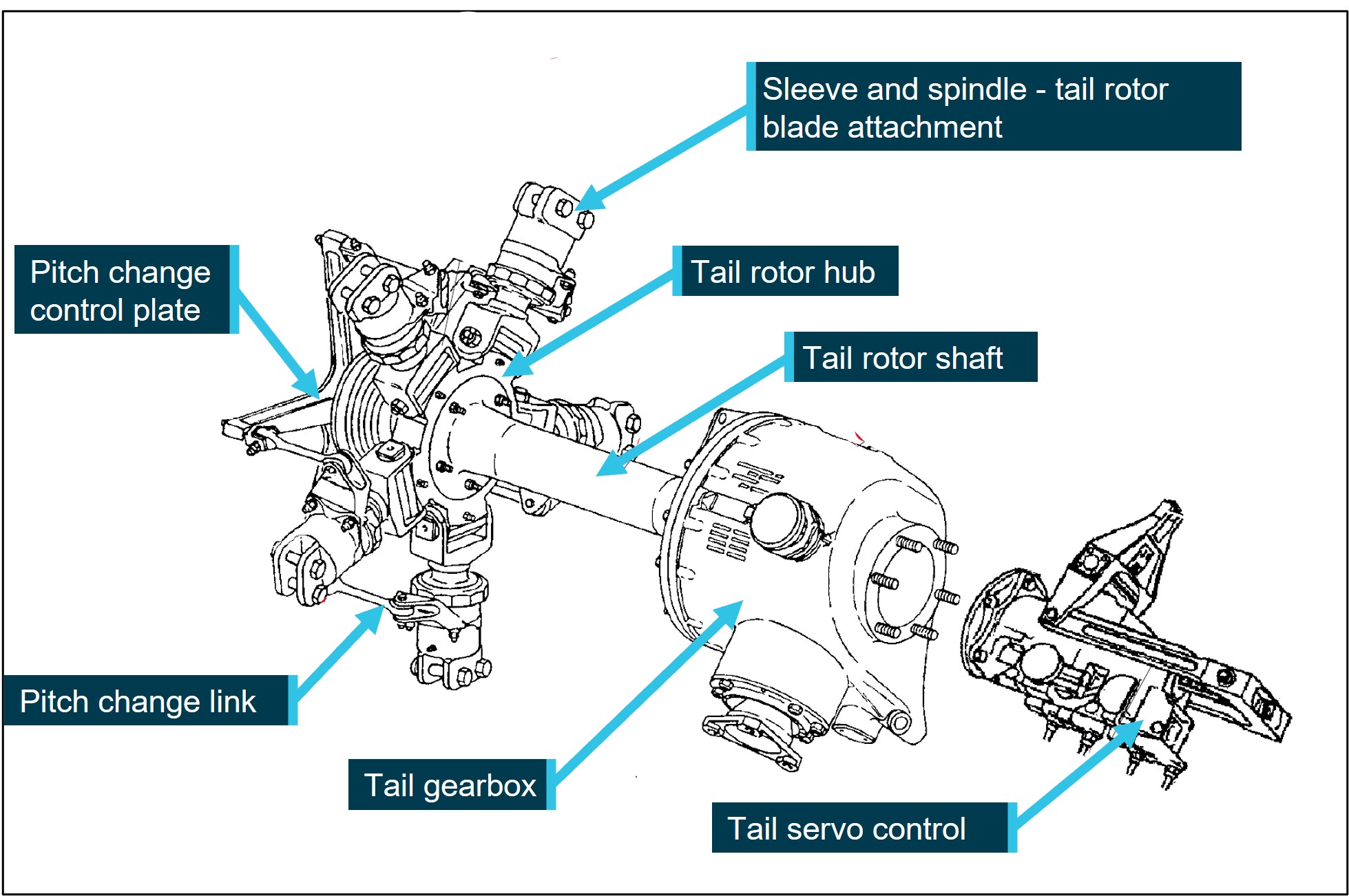
The AS332 tail rotor system comprises a 5-bladed tail rotor assembly that rotates in a counter‑clockwise direction. The tail rotor blades mount to the tail rotor hub and are driven by the tail gearbox via the inclined tail rotor shaft.
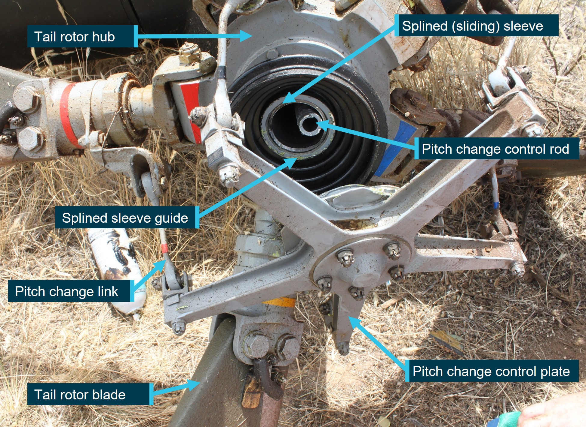
Tail rotor blade pitch control occurs in response to the pilot’s tail rotor pedal inputs via mechanical connection to the servo control. The servo control actuates a pitch change control rod located within the hollow tail rotor shaft and is connected to the pitch change control plate. The pitch change control plate is mounted to and supported by a splined sleeve that slides laterally in a guide located within the tail rotor shaft (Figure 1 and Figure 2).
Figure 1: Tail rotor gearbox and related components
Source: Airbus Helicopters, annotated by the ATSB
Meteorological information
The Bureau of Meteorology’s forecast conditions for Broken Hill and Albury airports were described as CAVOK[5] for the duration of the flight. Recorded weather observations for Hay aerodrome showed the mean wind speed varying between 12 kt and 15 kt from the north around the time of the accident.
The pilot reported that, following the departure from Broken Hill, and while cruising at about 3,500 ft, they were experiencing smooth flying conditions and had a tailwind of about 10–15 kt.
Recorded data
The helicopter was not fitted with a cockpit voice recorder or flight data recorder. A recent modification included the installation of a helicopter usage and monitoring system from which preliminary flight data was extracted by the ATSB.
The helicopter was also equipped with a Tracplus RockAIR portable tracking device. Additional navigational equipment was retained for further examination.
Wreckage and impact information
The helicopter impacted grass covered, flat terrain, in a slight left side down, but generally upright attitude facing about 320° (magnetic). The fuselage and belly sections were heavily compressed during the impact sequence, with the aft fuselage structure collapsing, resulting in the tail boom striking the ground. The tail boom ground strike then resulted in the vertical fin, with the tail gearbox and horizontal stabiliser attached, to separate from the tail boom. Following the ground contact and compression damage to the fuselage and tail boom, the helicopter rolled onto its right side. The wreckage was contained within the immediate area of the impact point and minimal forward projection of debris was noted.
The landing gear was found in the down position with the nose and left main gear sustaining significant damage. The compression of the belly resulted in considerable release of fuel from the fuselage belly tanks. The cabin‑fitted ferry fuel tanks were dislodged from the floor mounts in the impact but remained intact.
During the impact sequence, fractures occurred on the main and tail rotor systems, including an associated loss of blade material consistent with a ground strike. However, each of the blades remained securely attached to their respective attachment point.
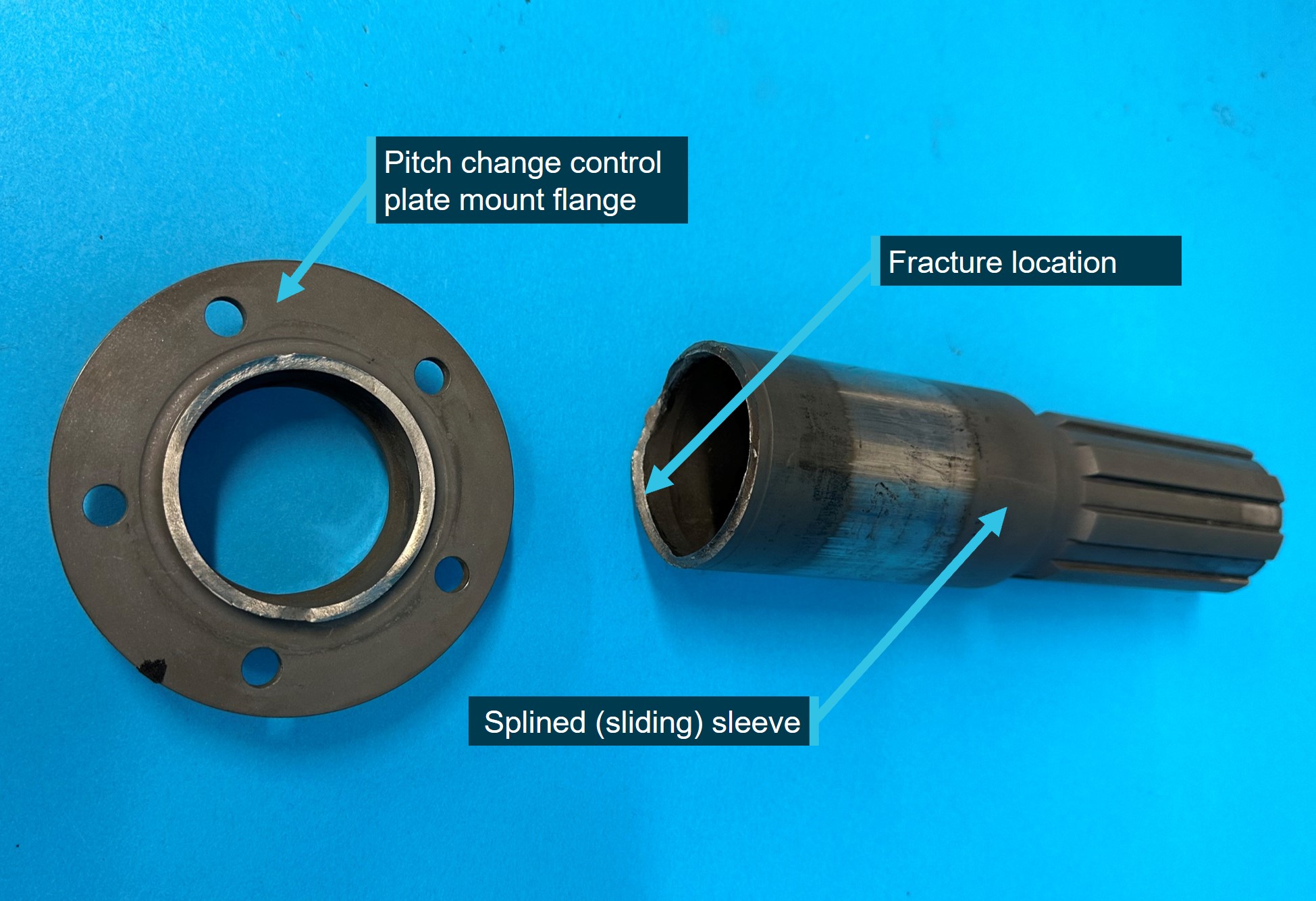
Examination of the wreckage found that the tail rotor pitch change control plate was detached from the tail rotor gearbox assembly and was the likely reason for the uncommanded yaw. Closer examination showed that the splined sleeve supporting the pitch change control plate had fractured at the mounting flange and the pitch change control rod was also fractured (Figure 2).
Figure 2: Tail rotor assembly with separation of pitch change control plate from gearbox
Source: ATSB
Component examination
Introduction
The fractured splined sleeve was examined at the ATSB’s technical facilities in Canberra, in the presence of representatives from the French Bureau d'Enquêtes et d'Analyses and Airbus Helicopters.
The manufacturer advised that the splined sleeve had no safe life limit,[6] and its serviceability was determined by on-condition maintenance requirements. The continuation in service of the component was contingent on the absence of corrosion or surface scratches as determined by visual inspection at specified intervals.
Component examination
Following the removal of its surface protective coating, the splined sleeve was identified as part number AS332A33 0070.20. The sleeve’s serial number was also identified to assist with determining the component manufacturing history.
Initial examinations of the fracture surface found that a fatigue crack had propagated around the majority of the splined sleeve’s circumference, leading to fracture of the sleeve in the section adjacent to the pitch change control plate mount flange. Further examination is to be conducted to determine the crack origin and identify the factors contributing to the cracking (Figure 3).
Figure 3: Separation of the pitch change control plate mount flange from the splined sleeve
Source: ATSB
Safety action
In response to this accident, Airbus Helicopters published safety related information, which included:
Safety Information Notice 4082-S-64 on 29 November 2024 that highlighted tail rotor assembly maintenance tasks, specific to inspection and lubrication requirements.
Alert Service Bulletin ASB AS332-64-20-003 on 23 December 2024 that specified an inspection for defects of the splined sleeve radius area of the control plate mount flange.
Further investigation
To date, the ATSB has:
examined the wreckage
collected items of evidence from the accident site
collected pilot and aircraft records
conducted interviews with relevant parties
liaised with Airbus Helicopters and the French Bureau d'Enquêtes et d'Analyses
conducted a preliminary examination of the splined sleeve.
The investigation is continuing and will include:
a further review and detailed examination of the splined sleeve
examination of the tail gearbox and components
an assessment of accident survivability aspects
a review of helicopter records and loading aspects
a review of the pilot’s qualifications and experience
analysis of recorded data.
A final report will be released at the conclusion of the investigation. Should a critical safety issue be identified during the course of the investigation, the ATSB will immediately notify relevant parties so appropriate and timely safety action can be taken.
Purpose of safety investigations
The objective of a safety investigation is to enhance transport safety. This is done through:
identifying safety issues and facilitating safety action to address those issues
providing information about occurrences and their associated safety factors to facilitate learning within the transport industry.
It is not a function of the ATSB to apportion blame or provide a means for determining liability. At the same time, an investigation report must include factual material of sufficient weight to support the analysis and findings. At all times the ATSB endeavours to balance the use of material that could imply adverse comment with the need to properly explain what happened, and why, in a fair and unbiased manner. The ATSB does not investigate for the purpose of taking administrative, regulatory or criminal action.
Terminology
An explanation of terminology used in ATSB investigation reports is available here. This includes terms such as occurrence, contributing factor, other factor that increased risk, and safety issue.
Publishing information
Released in accordance with section 25 of the Transport Safety Investigation Act 2003
Ownership of intellectual property rights in this publication
Unless otherwise noted, copyright (and any other intellectual property rights, if any) in this report publication is owned by the Commonwealth of Australia.
Creative Commons licence
With the exception of the Commonwealth Coat of Arms, ATSB logo, and photos and graphics in which a third party holds copyright, this report is licensed under a Creative Commons Attribution 4.0 International licence.
The CC BY 4.0 licence enables you to distribute, remix, adapt, and build upon our material in any medium or format, so long as attribution is given to the Australian Transport Safety Bureau.
Copyright in material obtained from other agencies, private individuals or organisations, belongs to those agencies, individuals or organisations. Where you wish to use their material, you will need to contact them directly.
[1]Collective: a primary helicopter flight control that simultaneously affects the pitch of all blades of a lifting rotor. Collective input is the main control for vertical velocity. Raising or lowering the collective also increases or decreases engine power to maintain rotor RPM as the rotor drag changes.
[2]Yawing: the motion of an aircraft about its vertical or normal axis.
[3]Autorotation: Autorotation is a condition of descending flight where, following engine failure or deliberate disengagement, the rotor blades are driven solely by aerodynamic forces resulting from rate of descent airflow through the rotor. The rate of descent determined mainly by airspeed.
[5]Ceiling and visibility okay (CAVOK): visibility, cloud and present weather are better than prescribed conditions. For an aerodrome weather report, those conditions are visibility 10 km or more, no significant cloud below 5,000 ft, no cumulonimbus cloud and no significant weather.
[6]Safe life limit: An airworthiness limitation that is applied to life limited parts, which have a predetermined lifespan after which they must be replaced to ensure safety.
Occurrence summary
Investigation number
AO-2024-060
Occurrence date
22/11/2024
Occurrence time and timezone
11:45 Australian Eastern Daylight Time
Location
41 km north-north-west of Hay Aerodrome
State
New South Wales
Report release date
28/01/2025
Report status
Preliminary
Anticipated completion
Q4 2026
Investigation level
Short
Investigation type
Occurrence Investigation
Investigation phase
Examination and analysis
Investigation status
Active
Mode of transport
Aviation
Aviation occurrence category
Collision with terrain, Loss of control, Transmission and gearbox
Occurrence class
Accident
Highest injury level
Fatal
Aircraft details
Manufacturer
Aerospatiale Industries
Model
AS332L1
Registration
N368EV
Serial number
2179
Aircraft operator
Forest Air Helicopters (Aust) Pty Ltd
Sector
Helicopter
Operation type
Part 91 General operating and flight rules
Activity
General aviation / Recreational-Other general aviation flying-Ferry flights
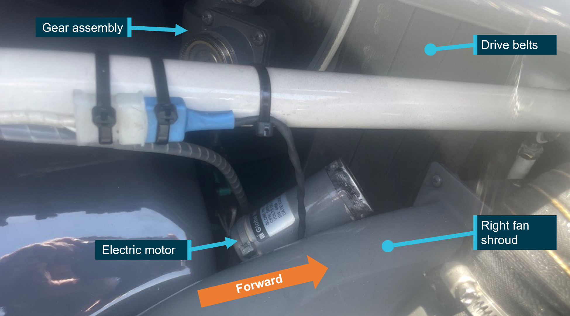
On 8 January 2023, the pilot of a Robinson R44 helicopter, registered VH-ZUJ, noticed a persistent clutch warning light on approach to Hamilton Island Airport, Queensland, and carried out the clutch warning light emergency procedure. The aircraft landed at Hamilton Island Airport, where ground crew found that the clutch actuator electric drive motor had separated from the gearmotor assembly and fallen between the drive belts and the right-hand fan shroud.
What the ATSB found
The ATSB established that during assembly of the gearmotor the required thread adhesive was not applied, or applied in a manner that did not prevent the loosening of the electric motor retaining nut. Consequently, over time, normal aircraft vibrations loosened the retaining nut, resulting in the clutch actuator electric motor separating from the gearmotor assembly in flight.
What has been done as a result
Robinson Helicopter Company advised that they are actively working with the component manufacturer to rectify identified quality issues with the gearmotor assembly and are considering updating the procedures for the inspection of the clutch actuator assembly.
Safety message
Personnel involved in maintenance and operation of R44 helicopters should be aware of the risks posed by the failure of this component, specifically the risk of a loose component interfering with the v-belts and impacting rotor drive. The ATSB encourages pilots and maintenance engineers to physically check the security of the R44 clutch gearmotor assembly on a regular basis.
Hand checking the motor for security, with electrical power off or visual inspection for motor rotation during operation are 2 methods that may detect a loosening motor prior to complete separation.
If a defect is identified, the gearmotor assembly should be replaced and the defect reported to the Civil Aviation Safety Authority and the manufacturer.
The investigation
Decisions regarding the scope of an investigation are based on many factors, including the level of safety benefit likely to be obtained from an investigation and the associated resources required. For this occurrence, a limited-scope investigation was conducted in order to produce a short investigation report, and allow for greater industry awareness of findings that affect safety and potential learning opportunities.
The occurrence
On 8 January 2023 a Robinson R44 helicopter registered VH-ZUJ was being used to conduct a number of local tourist charter flights from Hamilton Island, Queensland. The aircraft completed 7 flights and 6 engine starts that morning without incident, 4 of those flights were passenger‑carrying flights.
At about 1130 local time the aircraft departed Qualia helipad, with no passengers aboard, for a positioning flight to Hamilton Island Airport. On approach to runway 14, at about 300 meters from the threshold, the pilot noted the illumination of the clutch caution light.
The pilot waited for 10 seconds, then, as the light did not extinguish, they pulled the clutch motor circuit breaker in accordance with the clutch warning light emergency procedure in the pilot’s operating handbook. The landing was completed at Hamilton Island Airport and the aircraft was shut down without further incident.
Ground crew visually inspected the drive belt tensioner assembly and found that the clutch actuator electrical drive motor had separated from the gear assembly and was found between the drive belts and fan shroud. The motor was still attached electrically to the aircraft, and the gear assembly was securely attached to the drive belt tensioner assembly. (Figure 1)
Figure 1: Electric motor position
Source: Pilot. Annotated by the ATSB
Context
Drive belt system
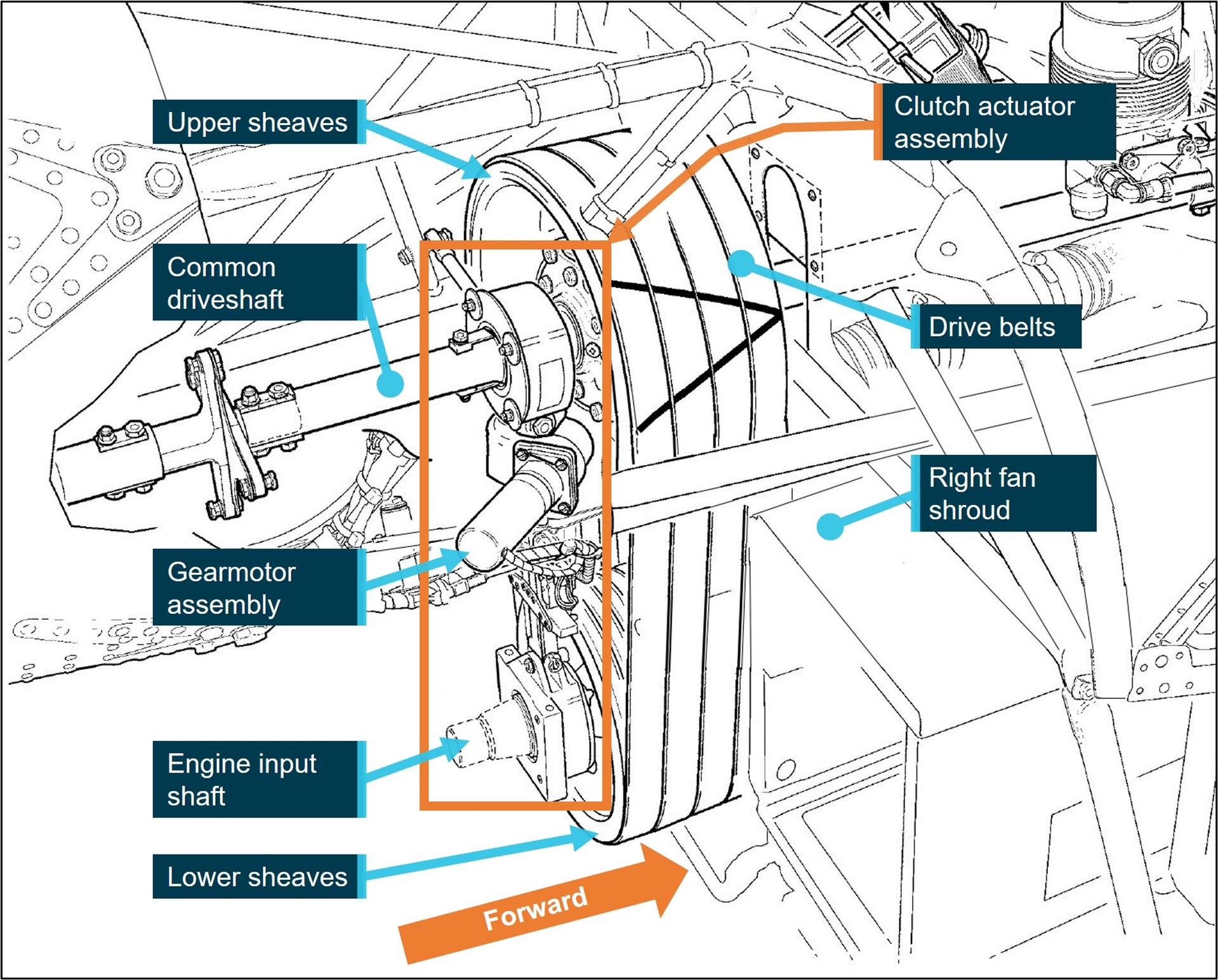
The Robinson R44 helicopter's rotor drive system incorporates a belt driven common shaft for main and tail rotor drive. Power is transmitted from the engine to the main and tail rotors through vertically mounted sheaves (also commonly called drive pulleys) and a v-belt arrangement (Figure 2). The drive assembly carries 4 double‑banded v-belts. Each drive belt consists of 2 single v-belts that are bonded by a common rubber backing (tie-band). The lower drive sheave is bolted to the output flange of the engine crankshaft, while the upper sheave is located immediately above on the common main and tail rotor driveshaft.
Before the engine is started, the clutch actuator is placed in the disengaged position, which leaves the v-belts slack and allows the engine to start and run freely without the load of the main and tail rotors. A pilot-operated, electrically‑driven actuator progressively tensions the drive belts and enables power transfer from the engine to the rotor system.
Figure 2: R44 clutch assembly
Source: Robinson Helicopter Company. Modified for clarity and annotated by the ATSB
Drive belt clutch system
The clutch actuator is vertically positioned between the upper and lower sheaves. When the actuator is engaged, the upper sheave and clutch shaft are moved upward, applying tension to the drive belts. A column spring arrangement within the clutch actuator senses the compressive load caused by increasing belt tension and stops the actuator gearmotor when the tension reaches a pre-set value. The actuator also incorporates up limit switches to prevent over extension due to belt stretching, and a down limit switch to set the clutch disengaged positions. The clutch gearmotor assembly uses an electric motor to drive the actuator, via a worm-drive[1] arrangement, which ensures that belt tension forces are not fed back into the actuator motor; this allows the motor to be de-energised and belt tension to be maintained. The gearmotor assembly is attached to the belt tensioner by 4 corrosion resistant screws. (Figure 2)
A clutch caution light is illuminated in the cockpit whenever the gearmotor is running, either engaging or disengaging the clutch. It is normal for the clutch caution light to illuminate briefly during flight as the actuator re-tensions the drive belts to maintain the correct drive belt tension.
Gearmotor assembly
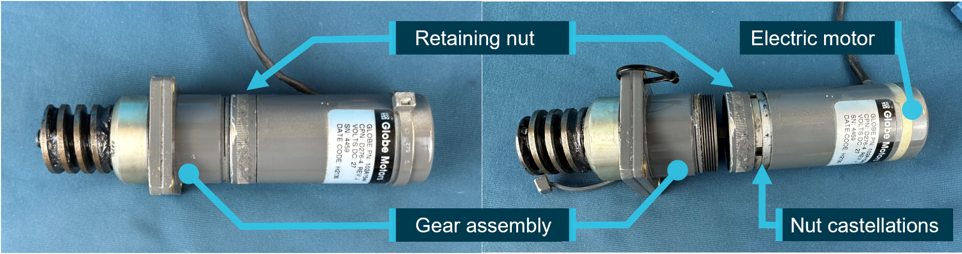
The clutch actuator electrical motor and gear assembly, collectively known as the gearmotor assembly, are factory assembled. The assembly is not field serviceable or repairable, requiring return to the manufacturer if unserviceable. The motor is attached to the drive gear by a threaded, free‑rotating, captive retaining nut. The retaining nut is secured with a commercially available thread locking adhesive and torqued with a c-spanner using castellations built into the nut, The electric motor case is then partially slid over the retaining nut, covering the castellations. (Figure 3) The design does not include a mechanical locking device, and no visual indication of loosening creep is embodied.
Figure 3: Gearmotor assembly
Source: ATSB
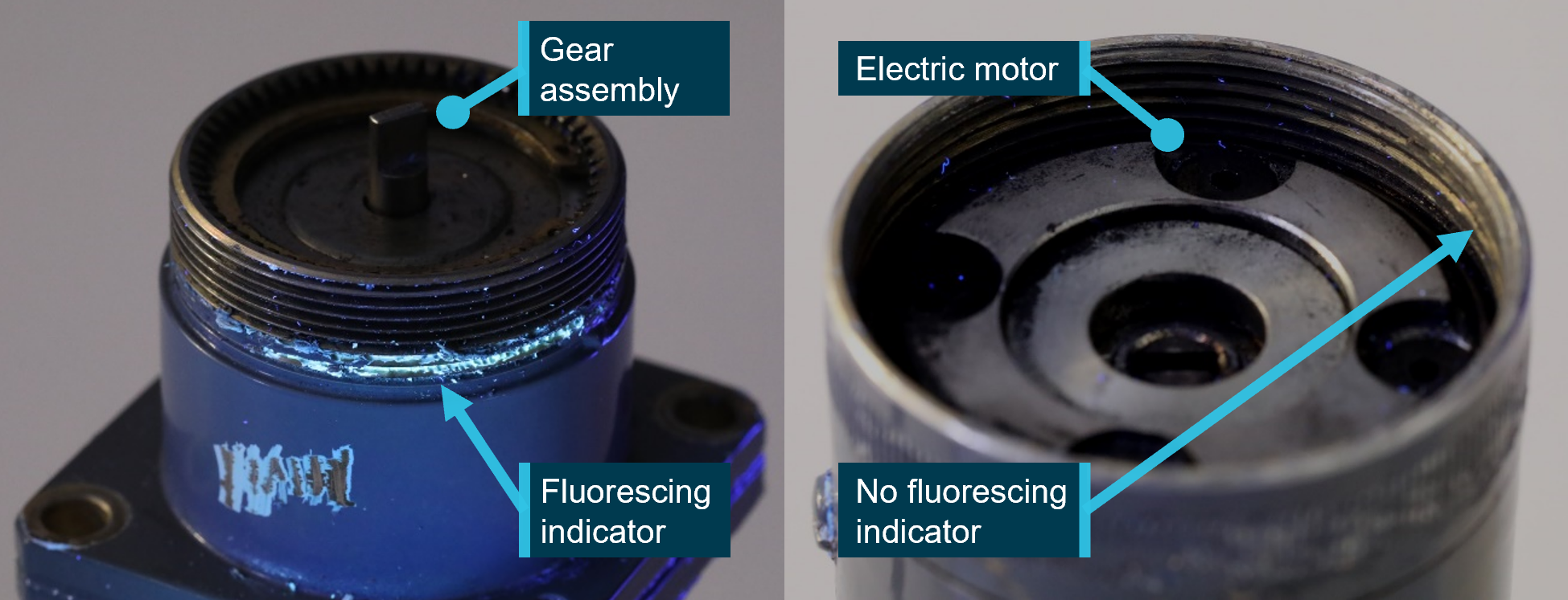
The incident gearmotor assembly was retained and inspected by the ATSB. The inspection noted the following (Figure 4):
No unusual damage to the threads of the electric motor or gear assembly was evident.
A black residue was found in the root of the gear assembly threads. This residue was not chemically identified due to an insufficient amount available for analysis.
The thread locking compound specified was designed to fluoresce in ultraviolet light to enable inspection of the fastener. The ATSB assembled a test piece with the locking compound and when disassembled the compound was evident when examined under ultraviolet light.
No evidence of thread adhesive was found on the engaging threads of either part of the incident gearmotor assembly under ultraviolet, or visible light conditions.
Fluorescent residue was found on a threaded section of the gear assembly, outside of the engaging threads section.
Figure 4: Gearmotor UV light inspection
Source: ATSB
Thread adhesive
Loosening of threaded fasteners subject to vibration or rotation is an established and understood phenomenon of aircraft operation.[2] Secondary locking devices and assembly torque are carefully designed to minimise the risk of the threaded fastener loosening in service. Thread adhesive can be used as a secondary locking mechanism to mitigate vibration‑induced loosening of threaded fasteners.
The thread adhesive specified for the gearmotor is a medium strength adhesive designed for permanent locking and sealing. Once cured, it has a wide operating temperature and requires parts to be heated to 232°C to reduce the adhesive strength for disassembly. The tightening torque applied to a threaded fastener is calculated, in part, by taking into account the opposing friction created between the threads during the torquing process.
Thread locking adhesive can have a secondary effect of lubrication of the threaded fastener during assembly and tightening. This lubrication allows a greater proportion of the torquing force to be converted into clamping force between 2 parts. The increased clamping force contributes to a reduction in vibration induced loosening.[3]
Gearmotor scheduled inspections
Scheduled inspection of the clutch actuator assembly is limited to a visual inspection and functional checking of the assembly during 100-hour/1-year inspections, up to its 2,200-hour overhaul life. The inspection procedure specifies inspections of the upper and lower bearings and testing of the limit switches, among other visual inspections. It does not specify a check for security of the gearmotor assembly, or of the electrical motor.
At the time of the incident the aircraft had a total of 133 flight hours, with the 100-hour inspection certified on 23 December 2022. All the required inspections were carried out on the clutch actuator assembly at this time, and no defects were noted by the certifying licenced aircraft maintenance engineer.
Pilot action
If the clutch caution light illuminates in flight, and does not go out within 10 seconds, the pilot’s operating handbook, clutch caution light emergency procedure, instructed pilots to:
…pull CLUTCH circuit breaker and land as soon as practical. Reduce power and land immediately if there are other indications of drive system failure (be prepared to enter autorotation). Have drive system inspected for possible malfunction.[4]
It is likely that the electric motor separated from the gear assembly sometime between the pilot engaging the clutch after start, and the continuous illumination of the clutch caution light immediately prior to landing. The clutch system attempted to re-tension the belts and as the motor had separated from the gear assembly, the motor ran continuously, illuminating the clutch caution light.
On noticing the clutch caution light and waiting the requisite 10 seconds, the pilot carried out the clutch caution light emergency procedure and was able to land immediately. Had the landing been delayed in this incident it is possible that the position of the electric motor, between the drive belts and right fan shroud, could have caused damage to the drive belts and created a hazard to the safety of flight.
Safety analysis
The gearmotor assembly process incorporated the application of a thread adhesive designed to act as a secondary locking device to prevent the inadvertent loosening of the electric motor due to normal helicopter vibrations in flight. ATSB inspection of the threaded sections of the incident gearmotor under ultraviolet light showed that the thread adhesive was not visible in an area that would reliably ensure the security of the motor. This resulted in loosening of the motor due to normal operating vibrations. The reason for the absence of thread locking adhesive on the mating surfaces of the threads could not be determined.
The absence of thread adhesive during assembly, and its associated lubricating effect, probably reduced the intended design clamping force between the gear assembly and electric motor. It is important to note that the residue found in the gear assembly threads was not chemically identified so the impact it had on adhesion or lubrication, could not be assessed. The extent to which these factors influenced the failure of the gearmotor assembly was not determined, but it is possible that a reduced assembly clamping load contributed to the failure.
The integrity and effectiveness of thread adhesives are difficult to determine by visual inspection alone, and generally require specialised tooling or procedures to accurately assess. It is therefore likely that the inspecting licenced aircraft maintenance engineers would have been unable to have detected the gearmotor defect by visual inspection, had it existed at the time of the last scheduled inspection.
Findings
ATSB investigation report findings focus on safety factors (that is, events and conditions that increase risk). Safety factors include ‘contributing factors’ and ‘other factors that increased risk’ (that is, factors that did not meet the definition of a contributing factor for this occurrence but were still considered important to include in the report for the purpose of increasing awareness and enhancing safety). In addition, ‘other findings’ may be included to provide important information about topics other than safety factors.
These findings should not be read as apportioning blame or liability to any particular organisation or individual.
From the evidence available, the following findings are made with respect to the drive belt tensioning motor failure involving Robinson Helicopter R44, VH-ZUJ, at Hamilton Island Airport, Queensland on 8 January 2023.
Contributing factors
Thread adhesive was not applied to the threads or applied to the threads in a manner that would effectively prevent the in‑service loosening of the motor.
The gearmotor electric motor separated from the gearmotor assembly due to normal aircraft vibrations.
Safety actions
Whether or not the ATSB identifies safety issues in the course of an investigation, relevant organisations may proactively initiate safety action in order to reduce their safety risk. The ATSB has been advised of the following proactive safety action in response to this occurrence.
Safety action by Robinson Helicopter Company
Robinson Helicopter Company advised that they are actively working with the component manufacturer to rectify identified quality issues with the gearmotor assembly and are considering updating the procedures for the inspection of the clutch actuator assembly.
Sources and submissions
Sources of information
The sources of information during the investigation included:
the pilot of the incident flight
Robinson Helicopter Company
Helibiz (VH-ZUJ maintenance provider)
Globe Motors
Submissions
Under section 26 of the Transport Safety Investigation Act 2003, the ATSB may provide a draft report, on a confidential basis, to any person whom the ATSB considers appropriate. That section allows a person receiving a draft report to make submissions to the ATSB about the draft report.
A draft of this report was provided to the following directly involved parties:
United States National Transportation Safety Board
Whitsunday air services (Operator)
Helibiz
Robinson Helicopter Company
Globe Motors
the pilot of the incident flight.
Submissions were received from:
Robinson Helicopter Company
Globe Motors
The submissions were reviewed and, where considered appropriate, the text of the report was amended accordingly.
Purpose of safety investigations
The objective of a safety investigation is to enhance transport safety. This is done through:
identifying safety issues and facilitating safety action to address those issues
providing information about occurrences and their associated safety factors to facilitate learning within the transport industry.
It is not a function of the ATSB to apportion blame or provide a means for determining liability. At the same time, an investigation report must include factual material of sufficient weight to support the analysis and findings. At all times the ATSB endeavours to balance the use of material that could imply adverse comment with the need to properly explain what happened, and why, in a fair and unbiased manner. The ATSB does not investigate for the purpose of taking administrative, regulatory or criminal action.
Terminology
An explanation of terminology used in ATSB investigation reports is available here. This includes terms such as occurrence, contributing factor, other factor that increased risk, and safety issue.
Publishing information
Released in accordance with section 25 of the Transport Safety Investigation Act 2003
Ownership of intellectual property rights in this publication
Unless otherwise noted, copyright (and any other intellectual property rights, if any) in this report publication is owned by the Commonwealth of Australia.
Creative Commons licence
With the exception of the Coat of Arms, ATSB logo, and photos and graphics in which a third party holds copyright, this publication is licensed under a Creative Commons Attribution 3.0 Australia licence.
Creative Commons Attribution 3.0 Australia Licence is a standard form licence agreement that allows you to copy, distribute, transmit and adapt this publication provided that you attribute the work.
The ATSB’s preference is that you attribute this publication (and any material sourced from it) using the following wording: Source: Australian Transport Safety Bureau
Copyright in material obtained from other agencies, private individuals or organisations, belongs to those agencies, individuals or organisations. Where you wish to use their material, you will need to contact them directly.
[1] Worm-drive: Consisting of a worm gear driving a worm wheel oriented with their rotation axes at 90° to each other.
[2] Australian Journal of Mechanical Engineering, Vol 2, No.2. Mechanisms and prevention of vibration loosening in bolted joints. Fernando (2005)
[3] NRP-1228, NASA Reference Publication: Fastener design manual (1990).
[4] Robinson Model R44 pilot operating handbook: Section 3, Emergency procedures. Page 3-9. FAA Approved 21 October 2016.
On 15 July 2022, a Bell Textron 505 helicopter registered VH-VTB was conducting a scenic flight near Double Island, Queensland, with a pilot and 2 passengers on board. About 30 minutes into the flight, the pilot heard 2 brief, loud ‘grinding noises’ and elected to proceed to Cairns Airport.
While over the airfield, the grinding began again and did not stop. After 10-12 seconds, approximately 10 ft off the ground, the pilot heard 2 loud bangs, and the helicopter yawed to the right. In response, the pilot moved the throttle to idle, which stopped the yaw. A run-on landing was performed on the grass short of the assigned helipad. Subsequent inspection of the helicopter revealed that the tail rotor driveshaft had failed.
What the ATSB found
A section of the tail rotor driveshaft failed due to a bearing that seized and overheated in flight. The reason for the bearing seizure could not be determined. An examination of the bearings 2 days previously found no problems, and the adjacent bearing was well lubricated, with some very small points of damage on the bearing race indicating potential contaminants.
The pilot’s decision to adopt a shallow approach into Cairns, and to reduce throttle immediately following the tail rotor failure both assisted in controlling the helicopter following the uncommanded yaw, and allowed a safe landing.
Safety message
Unusual sounds and responses from an aircraft can be an indication of an imminent system failure. In this instance, the pilot’s decision to return to Cairns was probably influenced by the initial short duration of the unusual noises and overwater operation. While a safe landing on an airfield resulted, the occurrence also illustrates how quickly failures can occur.
Therefore, pilots experiencing any unusual vibration or noise should land as soon as possible and have the aircraft inspected prior to further flight. If an immediate landing is not possible then pilot should be prepared to conduct an emergency landing or ditching if the situation deteriorates.
The pilot elected to perform a shallow return approach and, as the aircraft approached overhead the airfield, the grinding noise began again. The noise continued as the pilot neared the designated helipad. After 10-12 seconds, while approximately 10 ft above the ground, the pilot increased the power slightly to transition into a hover for landing and a ‘couple of big bangs’ were heard from the rear of the helicopter. It immediately yawed approximately 45° to the right, and the pilot responded by moving the throttle to idle. The uncommanded yaw stopped as a result, and the helicopter’s forward motion combined with a 10‑12 kt headwind aligned it with the direction of travel.
With the main rotor RPM decreasing, the pilot lowered the collective and executed a run-on[1] landing on a grass strip in the undershoot of the assigned helipad. The passengers disembarked and the helicopter was shut down normally. A subsequent inspection found that the tail rotor driveshaft had failed and separated at a bearing near the aft firewall.
The United States Federal Aviation Administration (FAA) recommends shallow approaches followed by a run-on landing in circumstances where there is insufficient power to hover.[2] This allows the helicopter to gain additional lift from its forward motion up until it touches down.
In the specific event of a tail rotor drive system failure the FAA notes that the severity of the resulting yaw is reduced by low power and high airspeed. Less power means a smaller reaction from the airframe due to main rotor torque, and more airspeed allows the aerodynamics of the fuselage and vertical stabiliser to mitigate the yaw effect. Following an in-flight tail rotor failure, the FAA recommends an immediate reduction of power and lowering of collective to land the helicopter (via an autorotation if necessary).[3]
Component examination
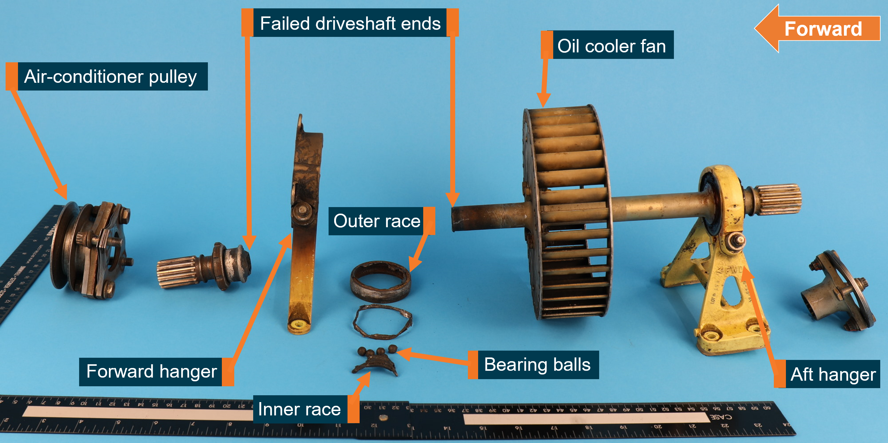
A section of the tail rotor driveshaft assembly known as the fan shaft was sent to the ATSB for detailed technical examination (Figure 1). This section of the driveshaft also drove the oil cooler fan, as well as cabin air-conditioning via a pulley and drive belt. In a functional fan shaft assembly, the engine drives the fan shaft which connects to the rest of the tail rotor driveshaft and ultimately, the tail rotor itself. The forward and aft hangers restrain the fan shaft via ball bearings that are clamped in each hanger using a nut.
Figure 1: The fan shaft and associated components removed from VH-VTB
Source: ATSB
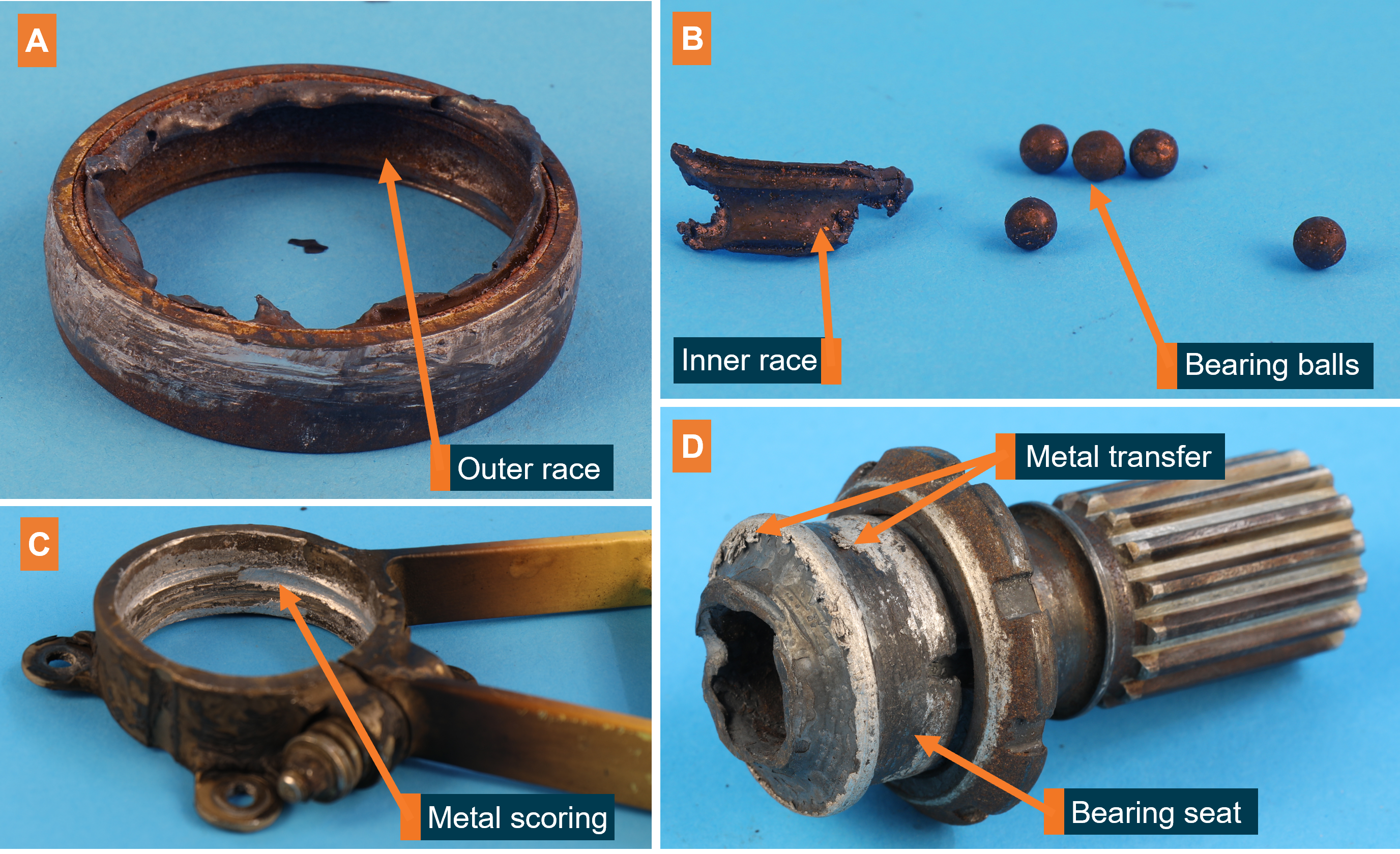
The driveshaft failed adjacent to the bearing seated inside the forward hanger. Blackening of the hanger, shaft and bearing components was present, indicative of exposure to high heat. The fracture surface closest to the bearing also appeared to be deformed due to heat exposure (Figure 2, D). Metal transfer on the bearing seat was likely from the adjacent inner race. No grease was observed in the bearing, though it might have been slung out or dissociated due to the high temperatures.
The outer race of the bearing was intact, but showed signs of corrosion (Figure 2, A). The inner race of the bearing had disintegrated, and only a small portion was found, along with only 5 bearing balls (Figure 2, B). Deep rotational scoring was observed on the inner face of the hanger and the outside of the outer race—normally clamped together during operation (Figure 2, C). The nut used to clamp the hanger to the bearing was still present, and a stripe of torque seal on the nut indicated that it had not backed off since it was last tightened. Metal was transferred onto the surface of the fan shaft, where the inner bearing sat during operation.
Figure 2: Damaged components of the failed bearing (A, B), hanger (C), and fan shaft (D)
Source: ATSB
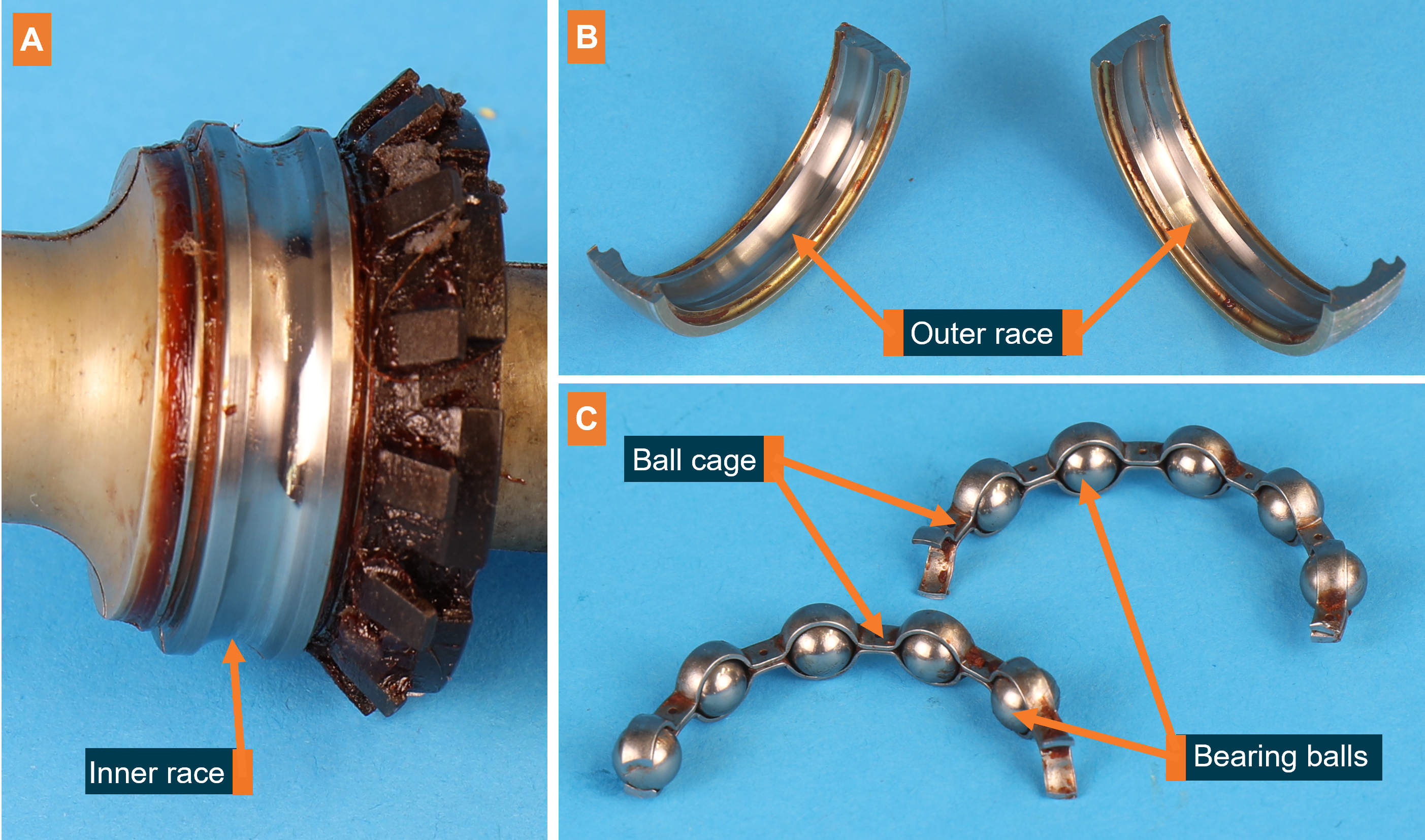
For comparison, the aft bearing was sectioned and examined for signs of damage (Figure 3). There were no signs of rotational scoring between the bearing and the aft hanger. The bearing contained sufficient grease, which had the same appearance as Mobilgrease 28. The grease showed no signs of contamination.
Figure 3: The aft fan shaft bearing, sectioned and disassembled.
Source: ATSB
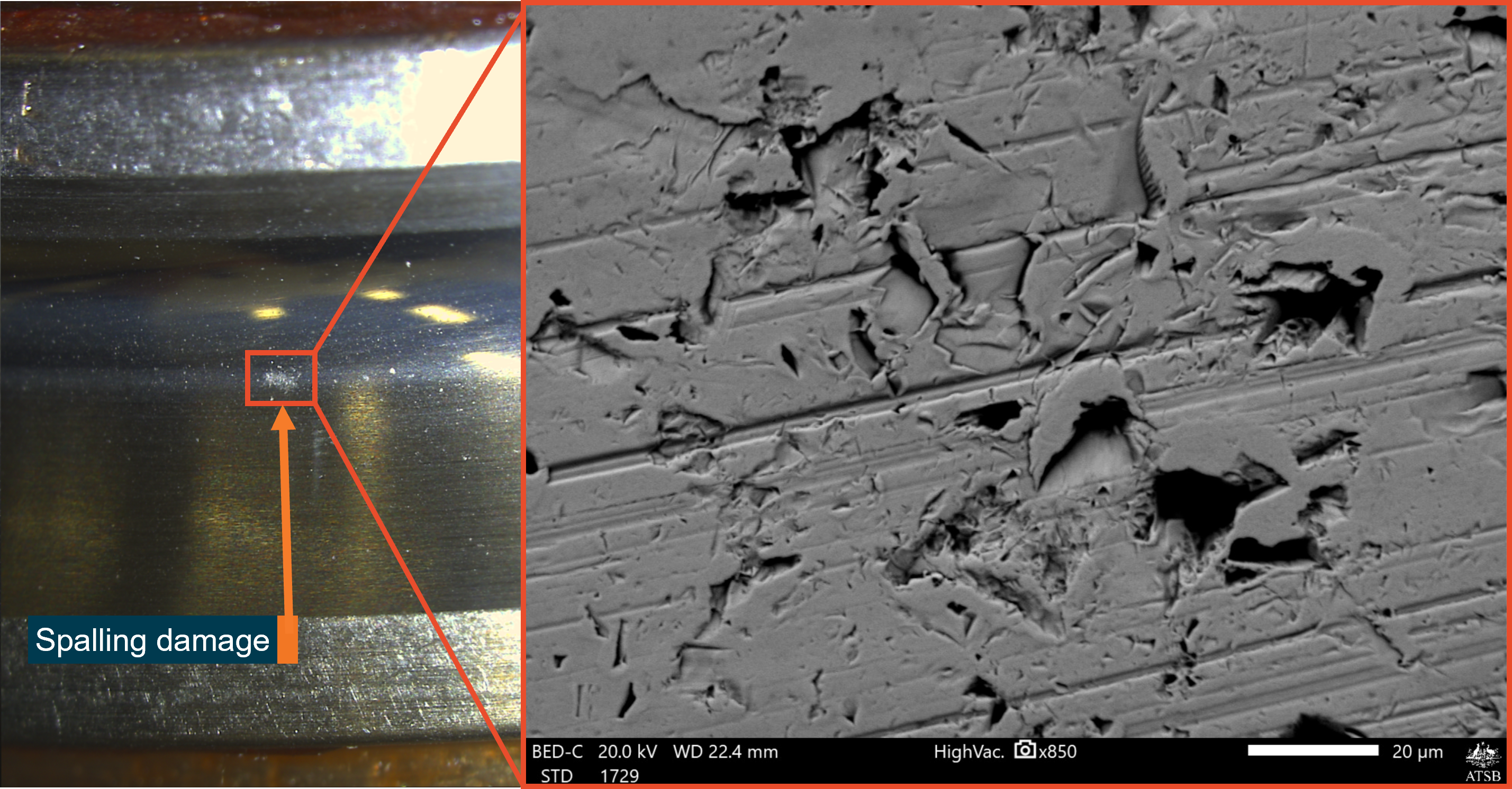
On the aft bearing, surfaces of the inner and outer bearing race were in good condition, with some very small points of spalling damage[4] on the inner race where contact would be made with the balls (Figure 4). No other mechanical damage associated with bearing degradation was observed (Figure 3, A and B). Likewise, there was no damage to the bearing balls or the ball cage retaining them (Figure 3, C).
Figure 4: Inner race spalling damage seen through an optical microscope (left) and electron microscope (right)
Source: ATSB
Aircraft maintenance
At the time of the incident, the helicopter had accrued 1,392.5 hours total time in service. The tail rotor driveshaft and associated bearings were the original parts installed when the operator received the new helicopter from Bell. The forward and aft fan shaft bearings were lubricated 246 flight hours previously using Mobilgrease 28, as part of the helicopters most recent 300-hourly inspection. This was done in accordance with Bell Textron’s maintenance schedule.
Two days before the incident, a different pilot heard a strange noise coming from what was thought to be the engine of VH-VTB. After an engine shutdown and restart the noise persisted. The helicopter was grounded for an inspection by maintenance personnel, but the noise could not be replicated. The helicopter was examined, including the tail rotor driveshaft. Bearings were inspected for signs of heat damage, excessive temperature, or noise, but no abnormalities were found and the helicopter returned to service. The pilot from the incident flight heard a recording of the initial noise, but did not believe it was the same ‘metal-on-metal’ sound heard during the incident, describing it as more of a vibration.
Comments from Bell Textron
Bell was not aware of any previous instances of bearing failure in 505 fan shaft bearings. Nor was it aware of any bearing failures in the 206 model helicopters, which use a similar drivetrain. Bell raised the possibility of air-conditioner belt tension or damage to the air-conditioner pulley splines as potential contributing factors. However, the splines were found to be in good condition and the operator reported that the belt had been installed in accordance with Bell’s maintenance schedule.
Other bearing issues
The failed bearing on VH-VTB associated with this incident was replaced with one from another 505, but after some time in service, maintenance personnel heard a ‘slight rumbling sound’ coming from the replacement bearing. It was subsequently sent to Bell for examination. The bearings and fan shaft assembly from the incident flight were also sent to Bell following the ATSB’s examination. At the time of writing the results of these examinations were not available.
The ATSB was also notified of another instance where an operator informed their maintainer of a strange and intermittent noise coming from one of the forward fan shaft bearings of a 505. Water was also found in the bearing when it was purged. The maintainer replaced the bearing in question, and there was no further examination of the removed bearing.
Safety analysis
During landing, a combination of heat and torque due to a seized forward fan shaft bearing resulted in failure of the fan shaft just aft of the bearing. The bearing seizure was evidenced by the disintegrated inner race, metal deposited on the bearing seat and signs of excessive heat around the bearing components and fan shaft. As a result of the bearing seizure, the fan shaft spun independently of the bearing, resulting in disintegration of the inner race. Scoring on the outer race and hanger indicated that at some stage, the bearing and fan shaft were also spinning together. It could not be determined when the bearing seized, but the noises heard by the pilot were likely either the fan shaft spinning on the bearing, or bearing spinning on the hanger. It could also not be determined whether the noise heard 2 days before the incident was related to the bearing failure.
Due to the amount of damage on the failed bearing, the reasons for its seizure could not be identified. The disintegrated inner race, corrosion within the outer race and damage to the hanger could all have been a result of the seizure, rather than factors contributing to it. No grease was observed following the failure, but it could have been slung out or dissociated due to the excessive heat. If the bearing was not properly greased, it would likely have resulted in abnormal noise or excessive heat when it was visually inspected 2 days previously, but neither were detected.
The aft fan shaft bearing showed no signs of corrosion or damage associated with improper lubrication. The only damage observed were small regions of spalling. Such localised damage was most likely due to a foreign contaminant within the bearing, since other possibilities such as poor tolerances, misalignment or manufacturing defects would have resulted in more widespread damage within the bearing. The forward bearing failure could have resulted from exposure to similar contaminants, but the faces of the inner and outer race were too damaged to permit an assessment of the failure mechanism.
ATSB investigation report findings focus on safety factors (that is, events and conditions that increase risk). Safety factors include ‘contributing factors’ and ‘other factors that increased risk’ (that is, factors that did not meet the definition of a contributing factor for this occurrence but were still considered important to include in the report for the purpose of increasing awareness and enhancing safety). In addition ‘other findings’ may be included to provide important information about topics other than safety factors.
These findings should not be read as apportioning blame or liability to any particular organisation or individual.
From the evidence available, the following findings are made with respect to the control issues involving Bell Textron 505, registration VH-VTB at Double Island, Queensland on 15 July 2022.
A shallow approach combined with timely and appropriate control inputs enabled the pilot to safely perform a run-on landing following the shaft failure.
Under section 26 of the Transport Safety Investigation Act 2003, the ATSB may provide a draft report, on a confidential basis, to any person whom the ATSB considers appropriate. That section allows a person receiving a draft report to make submissions to the ATSB about the draft report.
A draft of this report was provided to the following directly involved parties:
The submissions were reviewed and, where considered appropriate, the text of the report was amended accordingly.
Purpose of safety investigations
The objective of a safety investigation is to enhance transport safety. This is done through:
identifying safety issues and facilitating safety action to address those issues
providing information about occurrences and their associated safety factors to facilitate learning within the transport industry.
It is not a function of the ATSB to apportion blame or provide a means for determining liability. At the same time, an investigation report must include factual material of sufficient weight to support the analysis and findings. At all times the ATSB endeavours to balance the use of material that could imply adverse comment with the need to properly explain what happened, and why, in a fair and unbiased manner. The ATSB does not investigate for the purpose of taking administrative, regulatory or criminal action.
Terminology
An explanation of terminology used in ATSB investigation reports is available here. This includes terms such as occurrence, contributing factor, other factor that increased risk, and safety issue.
Publishing information
Released in accordance with section 25 of the Transport Safety Investigation Act 2003
Ownership of intellectual property rights in this publication
Unless otherwise noted, copyright (and any other intellectual property rights, if any) in this report publication is owned by the Commonwealth of Australia.
Creative Commons licence
With the exception of the Coat of Arms, ATSB logo, and photos and graphics in which a third party holds copyright, this publication is licensed under a Creative Commons Attribution 3.0 Australia licence.
Creative Commons Attribution 3.0 Australia Licence is a standard form licence agreement that allows you to copy, distribute, transmit and adapt this publication provided that you attribute the work.
The ATSB’s preference is that you attribute this publication (and any material sourced from it) using the following wording: Source: Australian Transport Safety Bureau
Copyright in material obtained from other agencies, private individuals or organisations, belongs to those agencies, individuals or organisations. Where you wish to use their material, you will need to contact them directly.
[1] A run-on/running landing is one in which a helicopter lands with significant forward motion, as opposed to landing from a hover, and maintains some forward motion after touching down. It is generally used when there is insufficient power to sustain a hover.
[4] Spalling is the shedding of material, or ‘spall’ from a surface, In a bearing, spalling at a single point is typically due to nicks, dents, or hard-particle contaminants.
On 7 December 2019, at about 1034 Eastern Daylight-saving Time, the pilot of an Overseas Aircraft Support UH-1H helicopter (formally known as Bell UH-1H or ‘Huey’ helicopter), registered VH-OXI, experienced a main driveshaft failure and hard landing near Crawford River, New South Wales, while engaged in fire control aerial work. The pilot was not injured, and the helicopter was substantially damaged.
What the ATSB found
The ATSB found that the pilot elected to abort the fire control aerial work and conduct a precautionary landing as a result of the failure of the driveshaft. While attempting to land, the pilot experienced an uncontrollable yaw to the right, resulting in a hard landing and substantial damage to the helicopter when the main rotor blades struck the ground and forcibly ejected the main gearbox, mast, rotors and KAflex® driveshaft from the airframe.
The helicopter’s KAflex® driveshaft, which transmits power from the engine to the main gearbox, failed due to a fatigue crack prior to the hard landing.
What's been done as a result
Following the accident, the Civil Aviation Safety Authority emailed Australian operators of UH‑1 helicopters a brief on the accident, which included a copy of a previously issued (2007) airworthiness bulletin on the subject of pre-flight inspection requirements for the KAflex® driveshaft. The requirements included checking the condition of all driveshaft hardware in addition to the pre-existing inspection requirements.
As a result of this occurrence, the helicopter operator replaced the KAflex® driveshaft on their other UH-1H helicopter with a new driveshaft. For the new driveshaft, they implemented a maintenance routine to monitor the hours flown and time-in-service and included a scheduled retirement time of 5,000 hours.
Safety message
In 2018, the driveshaft manufacturer provided a position paper to the United States Federal Aviation Administration, which recommended that driveshafts with the same part number as the accident helicopter should be replaced at 5,000-hours service, or, if the time-in-service could not be determined, removed and replaced. Any legacy driveshafts of the accident part number SKCP2281-103 can be sent to the manufacturer for modification to a new ‘safety of flight’ part number SKCP3303-1.
This accident highlighted the importance of pilots operating helicopters in the low-level environment to respond to the early symptoms of a problem immediately, and to be prepared to commit to a precautionary landing before the condition deteriorates to the point of a forced landing. In this case, the pilot responded without delay and was able to reach a safe landing site before a catastrophic failure of the driveshaft occurred.
The investigation
Decisions regarding whether to conduct an investigation, and the scope of an investigation, are based on many factors, including the level of safety benefit likely to be obtained from an investigation. For this occurrence, a limited-scope, fact-gathering investigation was conducted in order to produce a short summary report, and allow for greater industry awareness of findings that affect safety and possible safety actions.
The occurrence
On 7 December 2019, at about 0918 Eastern Daylight-saving Time (EDT),[1] the pilot of an Overseas Aircraft Support (OAS)[2] UH-1H helicopter, registered VH-OXI, departed the town of Wauchope, New South Wales for fire control aerial work 128 km to the south-west. The tasking was for fire-fighting, which involved the helicopter using a 150 ft long-line and a 1,200 L bucket to drop water on the fire grounds under the direction of the ‘air attack’ crew.[3]
On arrival at the fire ground at about 1028, the pilot of VH-OXI made contact with the air attack crew. They directed him to the water source (Crawford River) for the uplifts, and the fire grounds for the drops. The pilot made an approach to the river where the operation of the bucket was tested, and the first water drop on the fire ground was conducted.
On return to the Crawford River for the second uplift, and immediately prior to filling the bucket, the pilot heard a momentary ‘burring’ noise with a ‘buzzing’ vibration through the airframe. The pilot aborted the uplift and started to transition away from the hover when the noise and vibrations resumed. The pilot noted the intensity increased when the collective lever was raised.[4]
The pilot radioed the air attack crew the intention to land, released the bucket, and initially tracked towards a clear area that was not a confined area.[5] However, the continuing noise indicated to the pilot that the condition of the helicopter was deteriorating and the pilot elected to divert to a small clearing, which required an approach to the hover prior to landing. The air attack crew broadcast an emergency radio call for the pilot while the helicopter was tracking to the clearing.
On approach to the hover, at a height of about 10 ft, the helicopter started to yaw to the right, which the pilot was unable to stop with the left pedal. At about 90° rotation to the right, the pilot closed the throttle to idle, which did not appear to slow down the rotation, and then ‘dumped’ the collective lever. The helicopter rotated about 180° from the approach heading before landing hard. The main rotor blades struck the ground in the forward left position (reference to the pilot’s seat), which resulted in the failure of the main gearbox mounts and the ejection of the main gearbox, mast, rotors and driveshaft from the airframe.
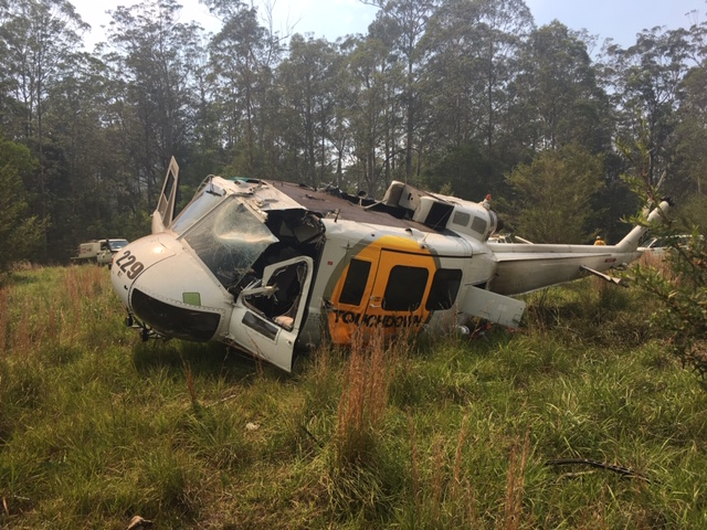
Rural Fire Service and National Parks personnel responded immediately and arrived at the accident site shortly after the pilot had exited from the wreckage (Figure 1). They extinguished a small grass fire that had been started by the helicopter. The pilot was transported to hospital by ambulance for observation and then released with nil injuries. The helicopter was substantially damaged.
Figure 1: Main wreckage site
Source: Operator
Context
Airframe inspection
The ATSB inspected the airframe at one of the operator’s hangar facilities on 20 December 2019. Due to the damage and disassembly for transport, the flight controls and transmission could not be inspected for mechanical continuity and correct operation. The engine could not be rotated and there was evidence of fine metallic particles present on the exhaust and combustion side of the power turbine, which indicated metal debris passed through the engine during the accident sequence.
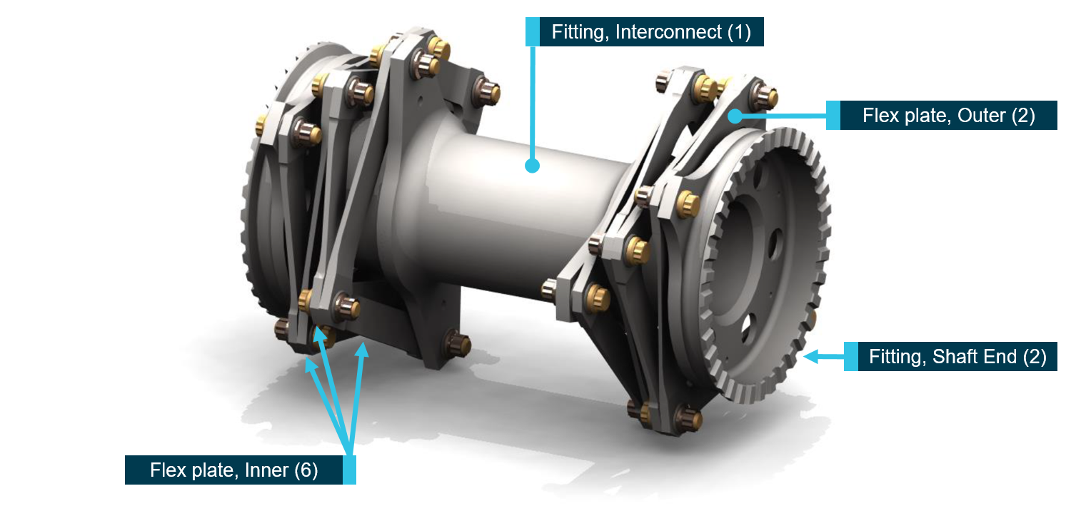
The KAflex® driveshaft (part number: SKCP2281-103), which transmits the drive power from the engine output to the main gearbox input, was found to have fractured into multiple pieces. The driveshaft uses flexible plates (Figure 2) to accommodate relative movement between the engine and gearbox, and was designed with an integral failsafe feature for continued flight in the event of a single flex frame fracture. It will permit a limited continued power operation (20 minutes demonstrated during qualification), enabling pilots to safely land the helicopter.
Figure 2: KAflex® driveshaft – key parts identified with the number of each part fitted annotated in brackets
Source: Kamatics Corporation, annotated by the ATSB
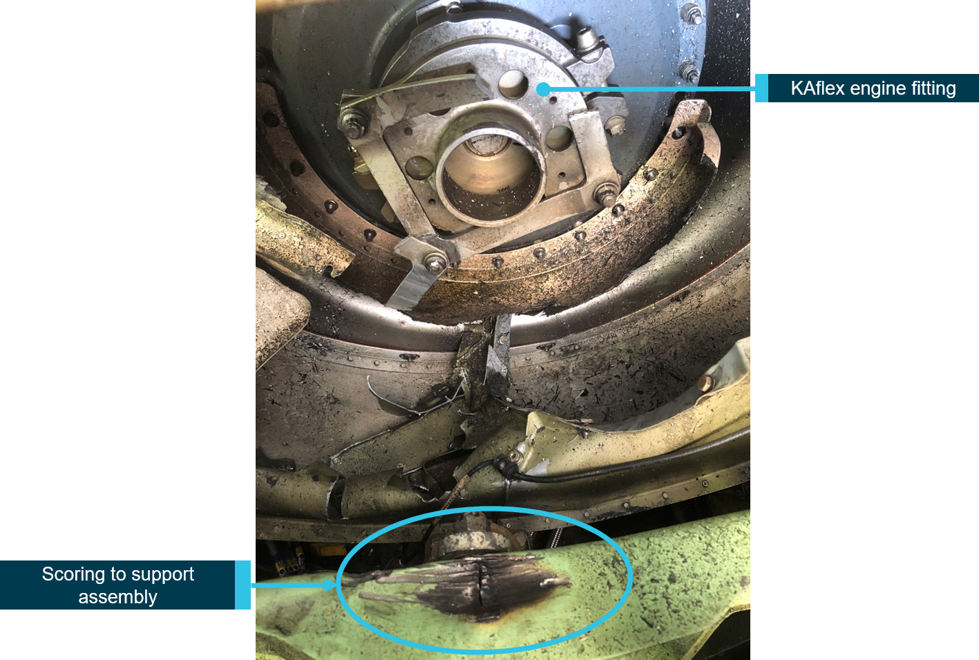
The visual inspection of the driveshaft noted a failure of one of the outer flex plate bolt holes, where the plate was bolted to the main gearbox-end fitting. In addition, there were five recessed washers missing from various fasteners. The rear transmission mount support assembly exhibited scoring below the location of the driveshaft gearbox-end fitting (Figure 3). Discoloration of a section of the failed outer flex plate was consistent with the scoring to the support assembly. The ATSB retained the helicopter’s KAflex® driveshaft (serial number 2136) for materials examination.
Figure 3: Scoring to the rear transmission mount support assembly
Source: ATSB
Materials examination
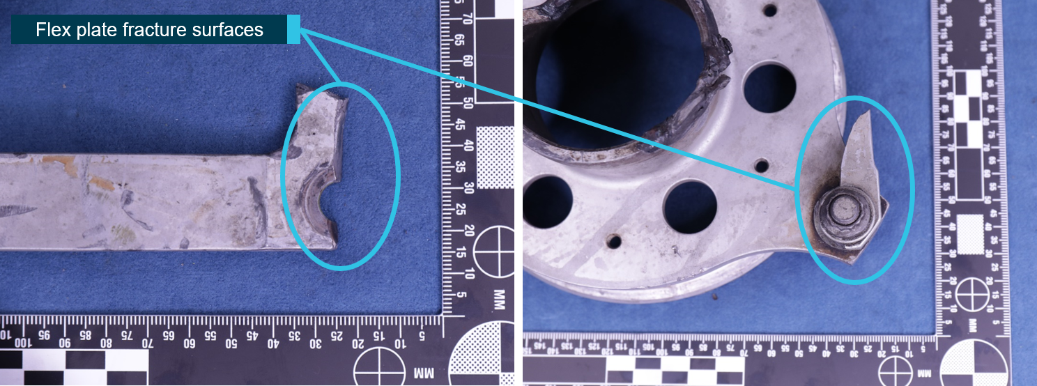
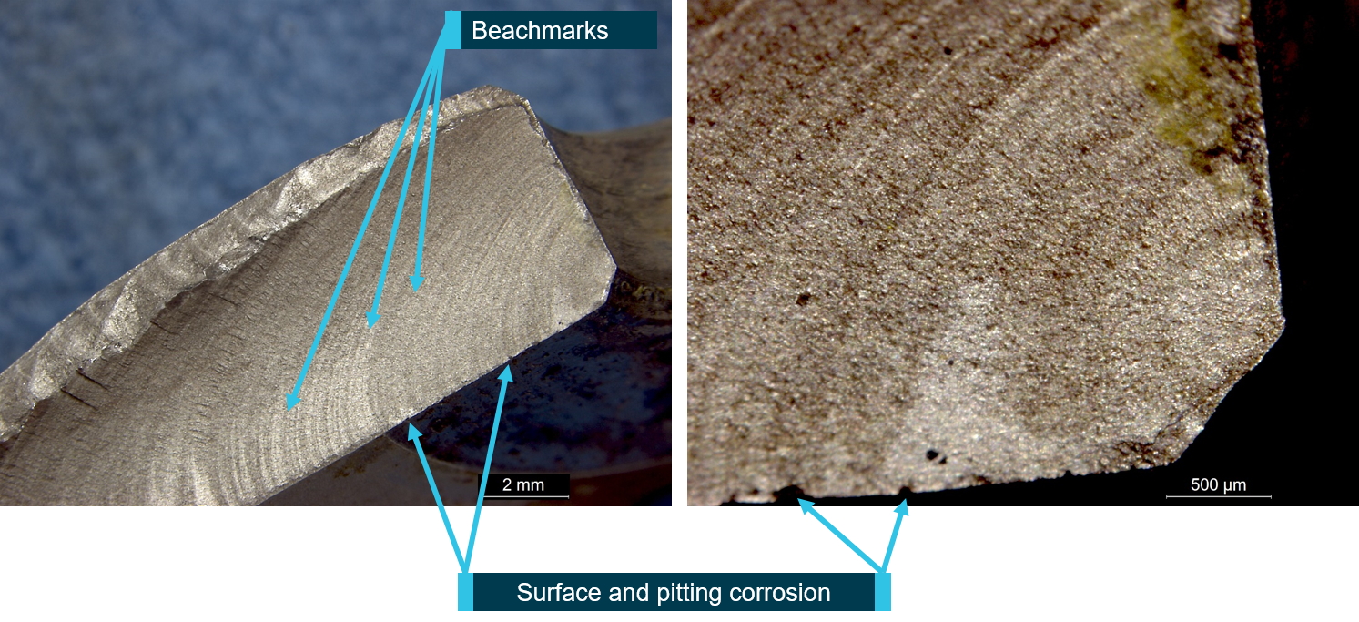
The flex plates from the driveshaft had fractured into multiple segments. The outer flex plate at the main gearbox-end fitting had fractured through the bolt hole, with a small section remaining attached at the join (Figure 4). Examination of the flex plate fracture surfaces revealed evidence of beachmarks, consistent with fatigue crack progression. The fatigue crack had propagated across about 90 per cent of the fractured surface. The surfaces surrounding the fatigue fracture exhibited evidence of surface corrosion and pitting (Figure 5).
Figure 4: Fractured bolt hole (left) and small section remaining attached (right)
Source: ATSB
Figure 5: Fatigue failure of flex plate
Source: ATSB
The five missing washers were from four fasteners, and in each of these locations the fasteners were loose and the flex plates free to move with respect to each other. Damage to the fasteners at these locations precluded any useful information with regard to torque values. A witness mark, consistent with a washer, was observed in all the locations. While some marks were more distinct than others, it was considered very likely that a washer had been present at each location at some stage in the life of the component. Figure 6 depicts the location of one of the missing washers.
Figure 6: Missing washer
Source: ATSB
KAflex® driveshaft overhaul and inspection
The manufacturer (Kamatics Corporation) reported that driveshaft SKCP2281-103, serial number 2136, was purchased in 1980 by the then owner, the United States (US) Army, as part of the UH‑1H driveshaft retrofit program. There was no time-between-overhaul (TBO) or retirement life for the driveshaft. There was a period in which the US Army implemented an overhaul program, but this was discontinued, and the driveshaft TBO/retirement became ‘on condition’. This was the accepted practice when the UH-1H helicopters were transferred to the civilian register in the restricted category.[6]
As the UH-1H was the driveshaft manufacturer’s only program without a TBO or retirement life, they worked with the US Army to develop a new safety of flight part number (SKCP3303-1). These driveshafts have a formal TBO of 5,000-hours, which is in accordance with the manufacturer’s other driveshaft programs. Any legacy driveshafts of part number SKCP2281-103 can be sent to the manufacturer for modification to part number SKCP3303-1.
In 2018, the manufacturer provided a position paper to the US Federal Aviation Administration with their concerns and recommendations for driveshafts in civilian UH-1H helicopters.[7] Their paper identified several different legacy part number driveshafts for the UH-1H. Part number SKCP2281-103 was identified as the only legacy part number that should be remaining in the field, and those with a serial number below 635 should be removed from service. In addition to recommending a ‘thorough Out of Aircraft inspection’, the manufacturer recommended to the FAA a removal from service for part number SKCP2281-103 driveshafts at 5,000-hours, or, if the time cannot be determined from historical records, ‘removal and replacement with a serviceable unit’.
The manufacturer reported that the Federal Aviation Administration has assigned a case number to review the issue of the UH-1H driveshaft in response to the manufacturer’s position paper.
The KAflex® driveshaft should not be disassembled outside of the factory. The manufacturer’s position paper and instructions for continued airworthiness for part number 3303 (Revision B), stated that all inspections should include checking for missing hardware (bolts, nuts, and washers), and a warning not to ‘disturb or tighten flex frame nuts or bolts. Evidence of turning fasteners by wrench or other means is cause for rejection.’
The maintenance organisation reported that the driveshaft was not being tracked as it did not have a service life and was an ‘on condition’ component. It was removed for an engine change about 74.5 hours prior to the accident and received a general visual inspection prior to installation. They reported that disassembly of the KAflex® driveshafts was not permitted and therefore there was no disassembly of it during the engine change.
Maintenance organisation comments
The maintenance organisation reported that they could not explain how the washers came to be missing, but were confident that they were all installed prior to the accident for the following reasons:
Quality pictures of the KAflex® bolts securing the end fittings were taken post-installation after the engine change. As the pictures were focused on the bolt securing the two clamps together, some of the KAflex® fasteners were not visible. However, the fasteners that were visible were all correctly assembled.
During the engine change, the licenced aircraft maintenance engineer, with more than 15 years of experience on the ‘Huey’, was doing some training with another engineer. They focused on the KAflex® and how to inspect the driveshaft correctly, especially when it was removed from the helicopter. During that training, they attempted to turn each fastener by hand to check if any were loose. In addition, they inspected for any evidence of fretting or cracks. No defects were found, and the driveshaft was installed.
The organisation used an unserviceable KAflex® driveshaft to check if it was possible to have one or two washers missing and the nut not be ‘shank bound’.[8] They found that a fastener with one washer removed could be tightened up enough that it could not be turned by hand. However, a fastener with two washers removed was shank bound with about a 10 thousandth of an inch gap between the nut and the flex plate.
In the case of the fastener missing two washers, they considered that the damage caused by a driveshaft having a shank bound bolt would cause a large amount of fretting. That damage would have been easily visible over the past 1,000 hours they had maintained it. In addition, they considered that the flex plate bolt hole would have elongated or caused large amounts of damage to the bolt. This damage was not evident.
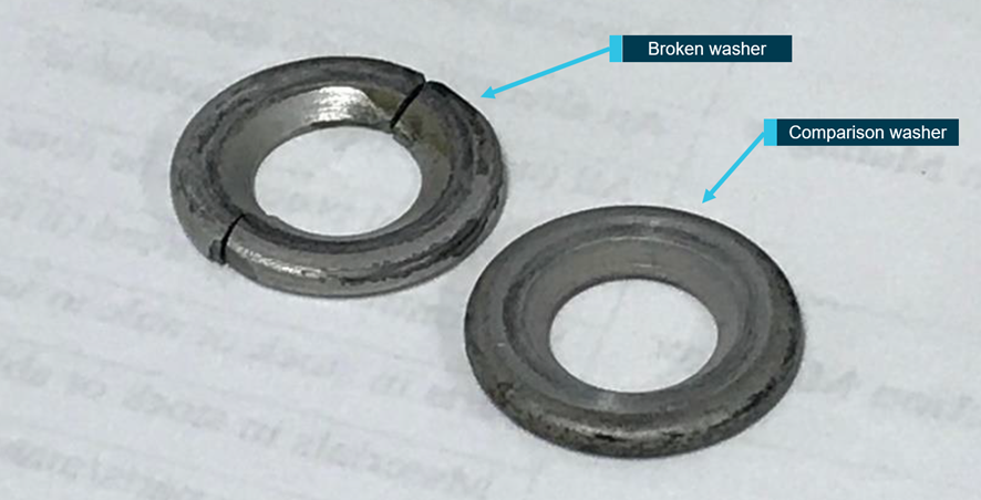
On 14 November 2020, following publication of the ATSB’s investigation report, an aircraft maintenance engineer found a broken washer in the wreckage while removing salvageable parts. The maintenance organisation notified the ATSB of the discovery and the broken washer was sent to the ATSB facilities in Canberra for analysis. In addition, the maintenance organisation provided further details, including photographs, about the maintenance history of the driveshaft.
Based on a photographic review of the broken washer, Kamatics reported the washer was consistent with those used on the KAflex® driveshaft. Analysis conducted by the ATSB revealed a high aluminium content, which was consistent with the SermeTel® coating used on these washers.[9]The dimensions were consistent with those for the KAflex® driveshaft recessed washer part number, the surface exhibited signs of fretting and there was no evidence of fatigue on the fracture surfaces. Kamatics reported that fretting is the usual type of wear found on the washers for driveshafts that have accumulated 4,500-6,000 hours operation, but they have never recorded cracked or broken washers during overhaul. Figure 7 below provides a comparison of the broken washer with a KAflex® driveshaft recessed washer.
The additional maintenance information and analysis of the broken washer suggested the most plausible scenario was that the missing washers failed as a result of the break-up of the driveshaft when the main gearbox was forcibly ejected from the airframe.
Figure 7: Comparison of washers
Source: Maintenance organisation, annotated by the ATSB
Safety analysis
Precautionary landing
As the helicopter approached a high hover over the Crawford River for a water uplift, the pilot experienced a ‘buzzing’ airframe vibration and ‘burring’ noise. The pilot immediately aborted the uplift, released the water bucket and tracked to a nearby clearing for a precautionary landing.
When in a hover position, just prior to landing, the helicopter started to yaw right. Despite the pilot’s attempt to stop the yaw, directional control could not be regained, which resulted in a hard landing. During the landing, the main rotor blades struck the ground, resulting in the failure of the main gearbox mounts and the forced ejection of the main gearbox, mast, rotors and KAflex® driveshaft from the airframe.
Flex plate fatigue failure
An inspection of the airframe revealed the KAflex® driveshaft exhibited a fatigue failure of the outer flex plate at a bolt hole where the plate was fastened to the main gearbox-end fitting. The observed scoring marks to the rear transmission mount support assembly were consistent with the failed driveshaft flex plate striking it during operation. This indicated that the driveshaft failure started before the hard landing and was consistent with the symptoms of noise and vibration reported by the pilot when overhead the Crawford River.
Findings
These findings should not be read as apportioning blame or liability to any particular organisation or individual.
While conducting fire control operations, the pilot detected a 'buzzing' vibration through the airframe with an associated noise, which necessitated a precautionary landing. During the landing directional control could not be maintained, resulting in a hard landing.
The helicopter's KAflex® driveshaft failed as a result of a fatigue failure of the outer flex plate attached to the main gearbox fitting.
Safety action
Whether or not the ATSB identifies safety issues in the course of an investigation, relevant organisations may proactively initiate safety action in order to reduce their safety risk. The ATSB has been advised of the following proactive safety action in response to this occurrence.
Civil Aviation Safety Authority
As a result of this occurrence, the Civil Aviation Safety Authority advised the ATSB that they took the following safety action:
Communication
The Civil Aviation Safety Authority inspected the driveshaft and then distributed an occurrence brief to all Australian operators of the UH-1 helicopters and variants with a copy of Airworthiness Bulletin 63-004: Kamatics Corporation KAflex Drive Shafts – Bell 407. This included the statement that the bulletin for the Bell 407 helicopters ‘is considered equivalent information for all UH-1 rotorcraft.’
Helicopter operator
As a result of this occurrence, the operator advised the ATSB that they took the following safety action:
Replacement part
The operator replaced the KAflex® driveshaft on their other UH-1H helicopter with a new driveshaft. They implemented a maintenance routine to monitor the hours flown and time‑in‑service of the new driveshaft and included a scheduled retirement time of 5,000 hours.
Maintenance organisation
As a result of the occurrence, the maintenance organisation advised the ATSB that they took the following safety action:
Addition of maintenance worksheet line item for all KAflex (and similar) driveshafts over-and-above the maintenance manual data checks. This line item covers a step to check all hardware against IPC [illustrated parts catalogue]/data (i.e. correct quantity and part number for all bolts, washers and nuts) and visual verification by means of applying Torque Sealant specified by KAflex OEM [original equipment manufacturer] as well as signing off the task. Subsequent checks will require that this torque seal is checked and reapplied if required, in order to verify a subsequent check of hardware has been made. This checklist item references Kamatics (OEM) ICA [instructions for continued airworthiness] 3303 Rev. B.
Purpose of safety investigations
The objective of a safety investigation is to enhance transport safety. This is done through:
identifying safety issues and facilitating safety action to address those issues
providing information about occurrences and their associated safety factors to facilitate learning within the transport industry.
It is not a function of the ATSB to apportion blame or provide a means for determining liability. At the same time, an investigation report must include factual material of sufficient weight to support the analysis and findings. At all times the ATSB endeavours to balance the use of material that could imply adverse comment with the need to properly explain what happened, and why, in a fair and unbiased manner. The ATSB does not investigate for the purpose of taking administrative, regulatory or criminal action.
Terminology
An explanation of terminology used in ATSB investigation reports is available here. This includes terms such as occurrence, contributing factor, other factor that increased risk, and safety issue.
Publishing information
Released in accordance with section 25 of the Transport Safety Investigation Act 2003
Ownership of intellectual property rights in this publication
Unless otherwise noted, copyright (and any other intellectual property rights, if any) in this report publication is owned by the Commonwealth of Australia.
Creative Commons licence
With the exception of the Coat of Arms, ATSB logo, and photos and graphics in which a third party holds copyright, this publication is licensed under a Creative Commons Attribution 3.0 Australia licence.
Creative Commons Attribution 3.0 Australia Licence is a standard form licence agreement that allows you to copy, distribute, transmit and adapt this publication provided that you attribute the work.
The ATSB’s preference is that you attribute this publication (and any material sourced from it) using the following wording: Source: Australian Transport Safety Bureau
Copyright in material obtained from other agencies, private individuals or organisations, belongs to those agencies, individuals or organisations. Where you wish to use their material, you will need to contact them directly.
The helicopter was cruising at about 1,500 ft AGL when the pilot heard a loud bang. The helicopter yawed to the left and the pilot noticed that he no longer had pedal control. He commenced an autorotation and turned into wind. The touchdown was relatively heavy, but the helicopter remained upright. After the pilot evacuated the cabin, he noticed that the auxiliary fuel tank had been damaged by the main drive shaft.
He was able to remove an ELT, survival gear and some drinking water before the helicopter caught fire and was destroyed. Wreckage examination found that the main rotor drive shaft forward flexplate had failed and pieces had punctured the auxiliary fuel tank. The examination determined that the forward flex plate had failed under load as a result of metal fatigue. The fatigue cracking had initiated at an area of corrosion pitting on the forward edge of the flex plate.
Areas of corrosion were also observed under sections of blistered paint at several other sites on the flexplate surface. The edges of the flexplate had been painted with a chromate primer and a protective topcoat. The paint had blistered and formed sites that acted to trap moisture next to the metal. Chlorides contained in the moisture then acted as the electrolytic agent that caused the corrosion. The investigation was not able to determine the source of the chlorides.
However, they could have resulted from environmental factors caused by the helicopter operation in coastal areas or over dry salt lakes. A further possibility was that 'hard' water (containing minerals) from artesian or other sources could have found its way on to the plates. The maintenance records indicate that with respect to main rotor drive shaft alignment, the helicopter was maintained in accordance with the manufacturer’s maintenance procedures.
The maintenance documentation indicated that the failed flexplate (p/n A947-1) had been in service for a total of 1,249 hours. Crack initiation to failure occurred over 350 flights on the flex plate. Prior to this accident, a flexplate fitted to VH-HEW (BASI report 9301775) failed in similar circumstances. A similar failure has occurred in New Zealand. In the New Zealand example, the number of cycles to failure was not determined.
However, the total time in service for this component was 1,486 hours. The Bureau recently obtained a flexplate which had been in service for 4,500 hours and which showed no visible evidence of cracking. The manufacturer does not specify a service life for the flexplates.
Significant Factors
1. Localised corrosion pitting was created under regions of blistered and lifting paint on the edge of the flexplate.
2. Fatigue cracking had initiated from one area of pitting.
3. The flexplate failed as a result of fatigue cracking.
Safety Action
Based on preliminary information of this and the similar occurrence (report 9301775) the Bureau of Air Safety Investigation made the following Interim Recommendation which was responded to by the CAA:
Interim Recommendation (IR 930272) The Bureau of Air Safety Investigation recommends that the Civil Aviation Authority advise all R22 operators of these failures to the flexplates, institute fleet inspection for drive shaft flexplate integrity and introduce repetitive inspections for cracking at appropriate intervals considering the crack propagation rate of those items which have been examined. Dependent on the results of fleet examination and in consultation with the manufacturer and industry, consideration should be given to the imposition of flexplate life limitations.
The CAA response, in part, stated: 'Your recommendations are generally accepted, however the exact form of our requirement may vary after discussion with the manufacturer and the FAA.' Interim recommendation IR 930272 suggested that the CAA to consider, amongst other things, the imposition of a service life for flexplates.
In the light of information from the manufacturer, review of other flexplates and specialist report 75-93 this part of that recommendation may no longer be appropriate. Specialist report 75-93 on the failed flexplates from these two aircraft identifies that the deteriorated paint treatment on the edge of the flexplates indirectly contributed to the corrosion and ultimately the fatigue failure. It suggests that prevention could be achieved either by maintaining an adherent paint film on the plate or, alternately, by leaving the plate uncoated, thereby eliminating the possible entrapment of corrosives.
Following these two failures (and another in New Zealand) Robinson Helicopters P/L issued SB No. 73 on 15 March 1994. This SB requires an inspection of the forward flexplate Pt. No. A947-1 for corrosion and cracking and proposes an amendment to the R22 Maintenance Manual procedures in respect to this component. Although the bulletin requires an inspection within 25 hours, the status of the bulletin has not been classified mandatory.
The CAA in response to IR 930272 sent a letter to all Certificate of Registration holders of R22 aircraft advising of the flexplate failures. However, there is no mandatory requirement for R22 operators to have their aircraft inspected to determine flexplate serviceability in respect to these failures or to report findings for those who do have their aircraft inspected. The fleet status therefore remains unknown.
The Bureau of Air Safety Investigation therefore makes the following recommendation:
R940092
1. That the Civil Aviation Authority institutes a mandatory inspection to determine the status and condition of in-service flexplates in respect to deteriorated paint finish or the onset of corrosion. The results of these inspections together with component in-service history should be reported and analysed.
2. That the Civil Aviation Authority in conjunction with the manufacturer, whilst considering the fleet status, analyse all of the information now available, review current inspection periods and formulate inspection procedures which will enable the integrity of the flexplate material to be checked.
The flying instructor advised that at 300 feet, after taking off to the north from the eastern grass at Moorabbin, he first heard an odd noise and then felt a violent vibration through the airframe. He also noticed that rotor RPM had begun to diminish. Immediately he lowered the collective, closed the throttle, and carried out an autorotation into an area just outside the airfield boundary. The engine continued to idle from the moment of closing the throttle.
Engineers found that the aft bearing on the lower pulley assembly had disintegrated internally, and the forward bearing was rough. (This pulley assembly is part of the drive train which transmits engine power to the main gearbox via eight rubber belts.)
The bearing (part number 269A5050-78) which failed was lifed at 1800 hours. It failed at 741 hours total time in service and 246 hours since it was last inspected/greased. There was no evidence of lack of grease or overheating of the bearings.
Significant Factor
The following factor was considered relevant to the development of the incident:
Following lift-off, at approximately 50 ft AGL, the pilot heard a loud bang and drive to the main rotor was lost. In the subsequent heavy landing, the main rotor struck and severed the tail boom. The aircraft remained upright.
Wreckage examination revealed that, while under power, both main rotor drive belts had rolled off the drive pulleys. It was found that both the forward and intermediate flexplates had also failed. The front flexplate had fractured and separated first, causing the intermediate flexplate to fail when it was free to move forward out of alignment. The main rotor drive shaft assembly, including all broken pieces of the forward and intermediate flexplates, was removed from the wreckage and forwarded for specialist metallurgical examination.
The examination determined that the forward flexplate had failed under load as a result of metal fatigue. The fatigue cracking had initiated at an area of corrosion pitting on the forward edge of the flex plate. Areas of corrosion were also observed under sections of blistered paint at several other sites on the flexplate surface. The edges of the flexplate had been painted with a chromate primer and a protective topcoat. The paint had blistered and formed sites that acted to trap moisture next to the metal. Chlorides contained in the moisture then acted as the electrolytic agent that caused the corrosion.
The investigation was not able to determine the source of the chlorides. However, they could have resulted from environmental factors caused by the helicopter operating in coastal areas or over dry salt lakes. A further possibility was that 'hard' water (containing minerals) from artesian or other sources could have found its way on to the plates.
The maintenance records indicate that with respect to main rotor drive shaft alignment, the helicopter was maintained in accordance with the manufacturer's maintenance procedures.
The maintenance documentation indicated that the failed flexplate (p/n A947-1) had been in service for a total of 3,136 hours. Striations in the surface of the fatigue crack indicated that crack growth had occurred over a period of about 180 flights.
Subsequent to this accident, a flexplate fitted to VH-HBO (BASI report 9303302) failed in similar circumstances. Crack initiation to failure occurred over 350 flights on the flexplate which had been in service for a total time of 1,249 hours. A similar failure occurred in New Zealand. In the New Zealand example, the number of cycles to failure was not determined. However, the total time in service for this component was 1,486 hours. The Bureau recently obtained a flexplate which had been in service for 4,500 hours and which showed no visible evidence of cracking. The manufacturer does not specify a service life for the flexplates.
Significant Factors
The following factors were considered relevant to the development of the accident:
1. Localised corrosion pitting was created under regions of blistered and lifting paint on the edge of the flexplate.
2. Fatigue cracking had initiated from one area of pitting.
3. The flexplate failed as a result of fatigue cracking.
Safety Action
The safety deficiencies identified in this investigation were found to be similar to those identified in occurrence 9303302.
The Bureau of Air Safety Investigation issued a recommendation, R940092 with Air Safety Occurrence Report 9303302 and the recommendation is detailed in that report.
The helicopter was hovering about 30 feet over a swamp when the pilot heard a noise and the helicopter began to vibrate. The pilot flew the helicopter towards dry land, but it began to rotate around the main rotor mast. A tail rotor failure procedure was carried out and the machine landed in the water.
The helicopter suffered damage to the tail boom, drive shaft, uprights and cross tubes.
Subsequent examination revealed that the tail rotor extension shaft drive pin had failed at the tail rotor gearbox.
Occurrence summary
Investigation number
199300308
Occurrence date
20/02/1993
Location
7.5 km north-east of Woolner Station
State
Northern Territory
Report release date
11/03/1994
Report status
Final
Investigation type
Occurrence Investigation
Investigation status
Completed
Mode of transport
Aviation
Aviation occurrence category
Forced/precautionary landing, Transmission and gearbox