During a flight on 21 June 2009, a Gippsland Aeronautics GA-8 Airvan aircraft, registered VH-BFS, sustained a fracture of the right main landing gear axle assembly, resulting in separation and loss of the wheel and brake calliper. To assist their investigation of the occurrence, the Civil Aviation Safety Authority (CASA) requested the assistance of the Australian Transport Safety Bureau (ATSB) in the metallurgical examination of the fractured landing gear leg. While the examination provided some information on the nature and location of the failure, the amount of material abraded and lost from the fracture surface (as a result of landing on the fractured leg), precluded a full determination of the fracture mechanism.
______________
Released in accordance with section 25 of the Transport Safety Investigation Act 2003.
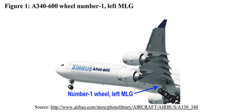
At 1200 Eastern Standard Time (EST) on 26 October 2005, the outboard bead heel of the number-1 wheel tyre on the left main landing gear (MLG) of an Airbus A340-642 aircraft, registered HS-TNA, separated from the outboard rim of the wheel assembly during a landing on runway 16 at Melbourne International Airport, Victoria. The landing was conducted during strong crosswind conditions. The aircraft was on a scheduled passenger service from Bangkok, Thailand, with a crew of 19 and 247 passengers. The copilot was the handling pilot for the flight. There were no reported injuries to any of the aircraft occupants.
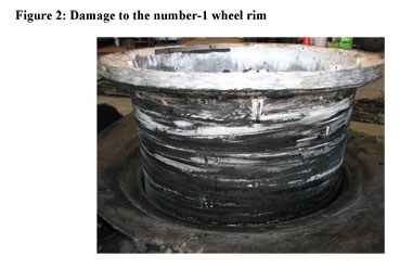
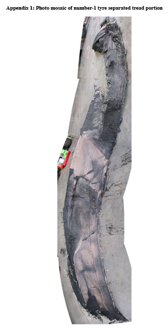
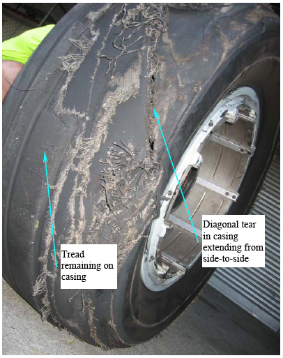
The number 1 wheel tyre deflated immediately after the bead heel separated from the wheel rim. The tyre then partially disintegrated during the remainder of the landing roll, and the tyre tread detached from the tyre casing (see Appendix 1).
Contact with the runway surface scored and scratched the outboard rim of the number 1 wheel assembly after the tyre deflated (see Figure 2).
Fragments of rubber dislodged from the disintegrating tyre resulted in some minor skin damage to the underside of the left wing and the left underside of the fuselage near the left MLG. Rubber fragments also broke off a small portion of the left MLG fairing door and dislodged a small inspection panel on the inboard side of the number 2 engine pylon. The disintegrating tyre also damaged a hydraulic brake line on the left MLG. The heat from the rear left MLG inboard wheel-brake assembly ignited hydraulic fluid, which leaked from the damaged brake line. The airport rescue and fire fighting service rapidly extinguished the fire.
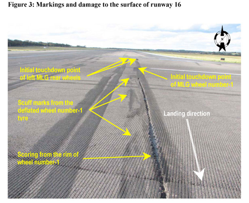
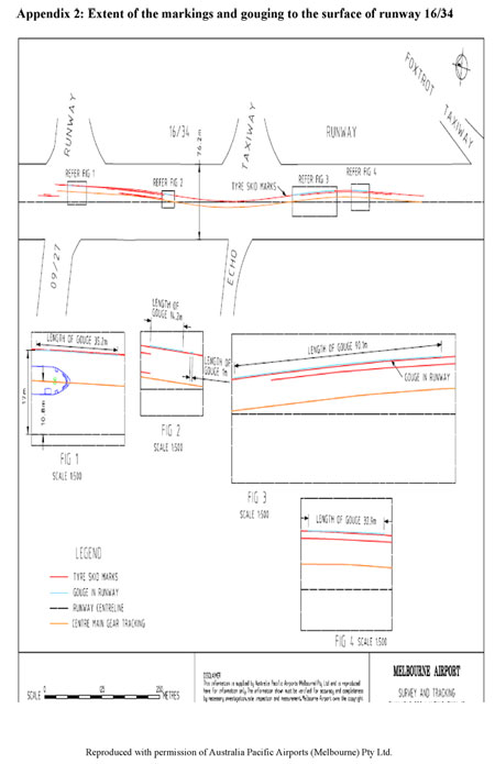
The number 1 wheel rim damaged the surface of runway 16 after the tyre separated from the rim (see Figure 3). Appendix 2 depicts the extent of the markings and gouging to the surface of runway 16/34 as a result of the occurrence.
The Bureau of Meteorology weather radar data indicated that a cold front passed through Melbourne International Airport at about 1130. The 0200 Coordinated Universal Time (1200 EST) aerodrome routine meteorological report for Melbourne Airport included information that the wind direction and speed were 260 degrees true (T) at 23 kts, gusting to 29 kts. Melbourne Airport automatic terminal information service 'Yankee', issued at 1130, included information that the wind direction and speed were 230 to 280 degrees magnetic (M) at 18 to 30 kts, with a maximum crosswind of 14 kts.
The preliminary solid state flight data recorder (SSFDR) parameters examined by the Australian Transport Safety Bureau (ATSB) included:
The data revealed that the wind direction during the landing approach from 850 ft RALT was about 250 degrees T, allowing for some minor variations. Wind speed from between 850 ft and 400 ft RALT was about 22 kts, with a maximum 27 kts occurring at 500 ft RALT. From 400 ft RALT, the wind speed reduced to about 18 kts. About 6 seconds before touchdown, the wind speed began to increase and reached a peak of 40 kts about a 1⁄2 second before the right MLG parameter transitioned from AIR to GROUND.
The aircraft's heading remained relatively constant between 166 and 168 degrees M from 850 ft RALT, then increased to 175 degrees M, coincident with the wind gust encountered just before touchdown. The aircraft touched down with 15 degrees right yaw ('crab'), on a heading of 175 degrees M, and rolled in a 5-degree right wing low attitude.
The right MLG parameter was the first to transition from AIR to GROUND at touchdown, followed by the left MLG, then the centre MLG. The centre MLG parameter then transitioned back from GROUND to AIR, followed by the right MLG, indicating a 'bounced' landing. The right MLG parameter transitioned back to GROUND 1⁄2 second later. The left MLG parameter remained in the GROUND parameter after the initial touchdown.
Touchdown vertical 'g' loading was about 1.6 'g', and lateral 'g' loading was about 0.4 'g' to the left, indicating that the aircraft was in a right sideslip.
The investigation is continuing and will further examine recorded flight and cockpit voice data to better understand the circumstances leading up to the occurrence.
Recorded data covering environmental conditions are also being examined to assess any effect on the aircraft.
Appendix 1
Appendix 2
Summary
At 1200 Eastern Standard Time on 26 October 2005, the outboard bead heel of the number 1 wheel tyre on the left main landing gear (MLG) of an Airbus A340-642 (A340) aircraft, registered HS-TNA, separated from the outboard rim of the wheel assembly during a landing on runway 16 at Melbourne Airport, Vic. The landing was conducted during gusting crosswind conditions.
The number 1 wheel tyre deflated immediately after the bead heel separated from the wheel rim. The tyre then partially disintegrated during the remainder of the landing roll, and the tyre tread detached from the tyre casing. Following the number 1 wheel tyre deflation, the crew-maintained control of the aircraft and, apart from some minor deviations to the left and right of the runway centreline, tracked along the centreline.
The aircraft touched down with 15-degrees of yaw as a result of its handling by the flight crew. That yaw angle was greater than recommended by the aircraft manufacturer and increased the risk of damage to the MLG at touchdown. It also increased the risk that the resultant ground slip angle of the MLG tyres would exceed the saturation point at which they entered a fully skidded state.
The pilot in command made dual side stick inputs during the latter stages of the approach intending to assist the copilot to maintain the attitude and trajectory of the aircraft. Those dual inputs compounded the handling difficulties being experienced by the copilot and increased the associated risks. Those risks could have been mitigated by the pilot in command taking control of the aircraft and pressing the side stick priority pushbutton at the point where he appeared to have become concerned about its attitude and trajectory, instead of making dual side stick inputs.
On 25 July 2009, a Boeing 737-7Q8 aircraft, registered VH-VBA, was taxiing toward the runway for departure at Melbourne aerodrome, Victoria, when the crew reported hearing a loud thud from the airframe. The crew of a passing company aircraft advised the crew of VH-VBA that they had lost a nose wheel tyre. It was subsequently discovered that the right wheel had detached from the nose landing gear (NLG) as a result of a fracture of the axle.
An Australian Transport Safety Bureau investigation of the NLG failure determined that the nose wheel had separated as a result of the initiation and propagation of a fatigue crack through the right, inboard bearing journal. The fatigue crack had originated under the influence of residual stresses in the steel surface associated with grinding damage during manufacture, and its initiation was probably hydrogen-assisted from plating processes applied to the journal bearing surfaces.
As a result of the occurrence, the aircraft operator conducted an immediate, fleet-wide inspection of axles with similar service history. To reduce the likelihood of future possible axle failures, the aircraft manufacturer conducted an audit of the landing gear supplier's processes and production records, in an attempt to establish the extent of the grinding problem. The aircraft manufacturer also released a communication to 737 operators and maintenance providers, detailing enhanced inspection recommendations for the identification of grinding damage.
On 9 April 2007, at 1703 Western Standard Time, the main landing gear of a Beech Super King Air 200 (registered VH-SGT) collapsed on touchdown at Perth airport. The aircraft was extensively damaged as a result of the collapse. No injuries were sustained by the pilot or passengers from the accident.
The Australian Transport Safety Bureau investigation revealed that two major system components had failed which could have prevented the landing gear from properly retracting/extending; the geared components within the right main landing gear actuator had fractured, and the left torque tube support bearing had seized from contamination and lack of lubrication. Although each component failure was apparently unrelated, the examination was not able to conclusively establish which failure had been the primary contributing factor in this landing occurrence. The Super King Air 200 aircraft landing gear system configuration was such that should either one of these component assemblies cease to function, extension or retraction of the landing gear would not have been possible.
As a result of this occurrence, the operator changed their system of maintenance to introduce an inspection interval and replacement schedule for all landing gear torque tube support bearings within their Super King Air 200 fleet.
The Civil Aviation Safety Authority released airworthiness bulletin 32-07 to all operators of Hawker Beechcraft 65, 70, Queen Air 90 and 200-series King Air aircraft that recommended changes to the maintenance schedule for landing gear components.
During the post-flight inspection of a Saab 340B passenger aircraft, the number two outboard main landing gear wheel was observed to have sustained noticeable damage. The flight crew reported that there was no prior indication of the failure, as the aircraft had handled normally during the landing and taxiing phase of the flight.
Subsequent examination found that the wheel inner rim had fractured away from the hub for approximately one-half of the total circumference. A circumferential fatigue crack had initiated at a location at the bead seat radius, and had propagated until a final ductile overload failure caused a section of the wheel rim to separate.
During the course of the investigation, it was found that the particular wheel design was being phased out due to recognised fatigue problems identified at the bead seat area.
Both the manufacturer and operator were aware of the increased fatigue susceptibility of the earlier wheel design and had established increased inspection regimes for those wheels remaining in service.
On 6 July 2008 at 1345 Eastern Standard Time, a SAAB 340B aircraft, registered VH-ZLC, departed the terminal at Orange aerodrome for a scheduled flight to Sydney. At the point of rotation during take-off, the right outboard wheel was observed to have detached from the aircraft. The crew elected to continue the flight to Sydney where the aircraft landed without further incident.
Examination of the components found that the right outboard wheel detachment occurred as a result of the failure of the outboard wheel bearing. It was possible that the failure was related to a lubrication or setting (installation) issue, however this could not be positively determined due to the degree of damage sustained by the bearing components.
As a result of this occurrence, the aircraft operator undertook a thorough internal safety investigation and implemented a range of safety actions, including a review of wheel bearing maintenance procedures, and an audit of main wheel axle nut torques across the fleet.
The aircraft manufacturer has informed the Australian Transport Safety Bureau that they have instigated an internal investigation and intend to publish a Service Bulletin to address the problem. The Service Bulletin will contain "on-wing" inspections and inspection and refinish actions during heavy maintenance.
Aircraft operator
The aircraft operator has informed the Australian Transport Safety Bureau that they have introduced a series of additional one-time and repetitive inspections of the landing gear trunnions on their 747 fleet. These additional inspections are:
A one-time detailed visual inspection of the trunnion at the first maintenance opportunity following the failure of the component on this aircraft.
Repetitive detailed visual inspections of the trunnion either before every international flight, or during the daily check for domestic flights.
A one-time inspection at the first appropriate maintenance opportunity of the following:
Detailed visual inspection of the internal surface of the trunnion bore by borescope.
Eddy current inspection of the external surface of the trunnion.
Eddy current inspection of the internal surface of the trunnion bore.
Ultrasonic inspection from the external surface of the trunnion, around the area in which the fracture originated, to measure the wall thickness and determine if it is less than the 0.180 inches allowable minimum.
Completion of these inspections without detection of a fault cancelled the requirement for the repetitive inspection detailed in item 2.
Repetitive inspections at every 1C Check of the following:
Detailed visual inspection of the external surface of the trunnion.
Detailed visual inspection of the internal surface of the trunnion bore by borescope.
Eddy current inspection of the external surface of the trunnion.
Eddy current inspection of the internal surface of the trunnion bore.
Significant factors
The wing landing gear trunnion did not conform to the design specifications. The component's wall thickness in the region of the failure was less than the allowable minimum and the internal bore had not been adequately shot peened.
Several fatigue cracks developed in the inner bore at the bore transition region.
The fatigue cracks were likely present during the last overhaul, but were not detected during the magnetic particle inspection.
The fatigue cracks developed until the loads during the pushback operation exceeded the residual strength of the component, leading to failure of the trunnion.
Analysis
The left-wing landing gear forward trunnion sustained a complete through-section fracture during the pushback at Sydney International Airport as a result of fatigue cracks in the bore of the trunnion. The fatigue cracks originated at an internal bore diameter transition and developed until they intersected to form a single crack.
The development and growth of the fatigue cracks was attributed to three principal factors:
the wall thickness of the trunnion was below the minimum required by the manufacture specifications
the surface had machining marks in the surface at the radius
the inner surface of the bore had been inadequately shot peened.
The effect of the reduction in wall thickness was to increase the working stress in the component. This increase in working stress reduced the number of cycles required to produce and develop fatigue damage.
The radius at the transition in the trunnion bore diameter is a natural stress concentration point when the item is smooth, but the presence of the machining marks on the surface of this radius provided further stress concentration. This stress concentration further reduced the number of cycles required to produce and develop fatigue damage.
The lack of adequate shot peening likely had a two-fold detrimental effect on the trunnion fatigue life. Firstly, as the smooth regions in the bore showed, effective shot peening obliterated the machining marks. Those marks remained in the unpeened areas and thus presented an additional stress concentration. Secondly, the absence of adequate shot peening denied the component the fatigue life improving qualities that shot peening brings.
Because there were no entries in the maintenance documents regarding repairs in the internal bore and the blending of the shot peened and non-shot peened areas, it is likely that the trunnion wall thickness was below the minimum design limit and was inadequately shot peened during original manufacture.
The presence of multiple secondary fatigue cracks in the component, also emanating from the root of machining marks, further verified that the failure was not due to a single material defect. As such, it would be likely to occur in other trunnions, which do not have the machining marks obliterated by the shot peening process.
The varying nature of the corrosion within the fatigue cracks and the demarcation between the various regions suggested that the cracks had existed during several overhaul cycles of the component. During overhaul, the component was subjected to chemicals that had a corrosive effect on the material, but would not be readily flushed away from a tight crack. Therefore, it is likely that the crack was present in the component at the last overhaul. The fracture surface indicates that the crack was approximately 4mm long and 1.6mm deep at the last overhaul in 2001.
The component had undergone the manufacturer required inspections at overhaul and no cracks were detected. The Magnetic Particle Inspection (MPI) method used to check the item for defects such as cracks is sensitive enough to detect a crack much smaller than the one suspected to have existed at the last overhaul. Possible masking of crack indications by the machining marks or a lack of expectation by the operator to find cracks in the region may have contributed to any cracks not being detected by the MPI operator.
The machining marks in the surface of the part can give non-relevant indications4 of cracks. Those spurious indications may mask true indications of cracks. If the operator was not aware that the machining marks should not be present, they would be likely to discount them and pass the component.
The aircraft manufacturer provided standard practices in relation to the inspection method used. These practices were general and were to be used by maintainers in developing their component specific procedures. Neither the overhaul procedure for the trunnion nor the general MPI process specification directed the MPI operator's attention to the radius in the bore diameter transition. Therefore, the expectation for an operator's repair shop to find cracks in that region would be low.
Because the manufacture documentation for the particular component was destroyed in 1994, the investigation could not determine how the trunnion was manufactured and released in a state that did not conform to the manufacture drawings. The overhaul and service instructions for the trunnion did not provide a mechanism by which the non-conformances could be detected.
Non-relevant indications are indications that are defect-like in appearance, but are due to the local geometry and features of the component. Heavy machining marks are one such
Factual Information
Sequence of events
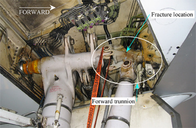
At about 1200 Eastern Standard Time on 30 May 2005, a Boeing Co 747-300 (747), registered JA8184, was being pushed back from its gate at Sydney International Airport for a scheduled passenger flight to Osaka, Japan. During pushback, the ground staff heard a loud cracking noise. The pushback was stopped and an inspection by the ground crew identified a structural failure in the left wing landing gear forward trunnion fork (trunnion), as shown in Figure 1 and 2. After an on-site inspection by the Australian Transport Safety Bureau (ATSB), the aircraft was moved to a hangar for maintenance and the fractured component was removed from the aircraft and sent to the ATSB for a detailed examination.
Figure 1 : Left wing landing gear
Figure 2: Looking up and outboard into wing landing gear well
Examination of fractured trunnion
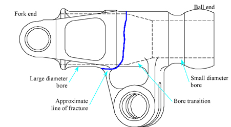
The trunnion had sustained a complete through-section fracture, located approximately mid-way between the ball-end and the fork-end (Figure 3).
Figure 3 : Fracture location on trunnion
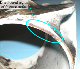
A general inspection of the fractured trunnion revealed a discoloured (orange/brown) region on the fracture surface (Figure 4) in the upper outboard region. The corroded nature of that region, compared with the adjacent bright fracture surfaces, indicated the presence of a pre-existing defect, and that the trunnion had been cracked for a period of time prior to the final failure during the pushback.
Figure 4 : Fracture surface
The fractured component was examined in a metallurgical laboratory under the supervision of the ATSB. Chemical analysis of a sample taken from the trunnion near the fracture showed that the material met the specification for AISI/SAE 4340M alloy steel. Metallographic examination confirmed a fine-grained lightly tempered martensitic microstructure, typical of the 4340M alloy in the hardened and tempered condition. The inner and outer surfaces were also observed to have been finished with a metallic type plating and painted with a surface primer and topcoat.
Hardness measurements taken indicated that the material had an ultimate tensile strength of approximately 275,600 psi (1900 MPa).
Wall thickness measurements taken around the fractured trunnion circumference showed that the minimum local wall thickness of 0.137 inches (3.48 mm) corresponded with the corroded and discoloured area of cracking.
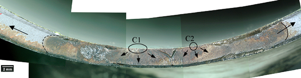
A detailed technical examination of the corroded region identified two transverse fatigue cracks originating at the inner surface of the trunnion bore (noted as C1 and C2 in Figure 5). The cracks had initiated approximately 11mm apart and had joined to form a single crack. This crack continued to grow until the final fracture occurred during the pushback.
Figure 5 : Fatigue crack development
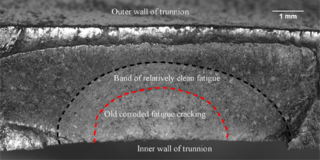
Crack C2 presented well defined fatigue progression marks, including several distinct regions of fatigue and corrosion (Figure 6). The region bounded by the red dotted line was a distinct region of heavily corroded fatigue cracking and was about 4 mm long and 1.6 mm deep.
Figure 6 : Fatigue progression and corrosion marks
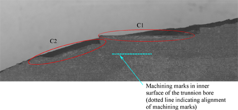
Close examination of the origins in the inner wall of the trunnion found that crack C1 had initiated from multiple closely spaced origins at the root of a machining groove, giving the appearance of a longer crack following the machining groove (or mark). Crack C2 had also originated at the root of a machining groove from multiple closely spaced origins, but over a much smaller distance before aligning with the principal stress plan1, resulting in the apparent difference in the planes of the cracks as shown in Figure 7. The plane of the initial cracks in both C1 and C2 were approximately parallel and were aligned with the machining grooves in the inner surface.
Figure 7 : Plane of crack origins
The inner and outer surfaces did not have a consistent surface roughness. Well defined machining marks were observed in the large diameter bore and to a lesser extent on the small bore. However, the outer surface and the taper region in the bore were relatively smooth without defined machining marks. The well-defined machining marks on the large and small diameter bore blended into the smoother surface of the taper region (that is, there was no abrupt change in surface roughness).
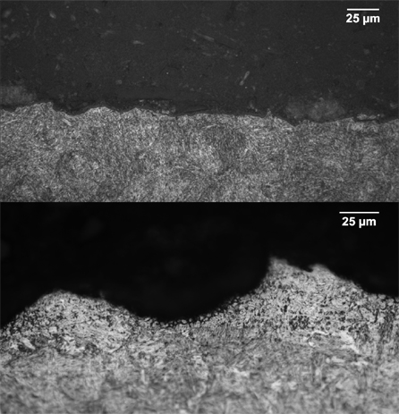
Examination of the surface microstructure in the region of the cracks revealed that the smooth regions (outer surface and taper section) had a thin layer of deformed material typical of a cold working process such as shot peening2. The area of surface deformation in the taper region ran out just before the radius (a few millimetres from the cracks). Figure 8 shows the differences in the surface roughness at a microscopic level (scale is 25µm, or 0.025 mm).
Figure 8 : Smooth surface (upper); surface with distinct machining marks (lower)
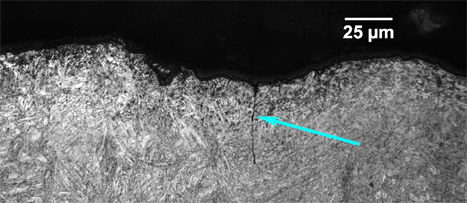
The sections taken from adjacent to the primary cracks for micrographic examination contained multiple independent fatigue cracks of various sizes. One example is shown in Figure 9. Each of these cracks originated in the root of the machining groove and were associated with shallow intergranular penetrations, which also existed in the roots of the machining grooves (Figure 8).
Figure 9 : Secondary fatigue crack indicated by arrow
Component manufacture
The landing gear trunnion was manufactured to the aircraft manufacturer's specifications by an approved external supplier. Both the supplier and the aircraft manufacturer informed the ATSB that the trunnion was manufactured at some time prior to 1975; however, the original manufacture documentation (including the manufacture plan and conformance records) was destroyed in 1994. The trunnion specifications were supplied by the aircraft manufacturer. Those documents included construction drawings and process specifications.
In the trunnion specifications, the aircraft manufacturer specified the use of 4340M steel, heat treated to an ultimate tensile strength of 275,000 to 300,000 psi. Therefore, the material used in the manufacture of the failed component met the steel alloy and strength requirements of the design.
The minimum allowable wall thickness specified3 for the trunnion at the location of the failure was 0.180 inches (4.57 mm). Therefore, the minimum wall thickness measured at the crack of 0.137 inches (3.48 mm) was 0.043 inches (1.09 mm) thinner than the design allowed.
Component maintenance
The maintenance documents supplied by the aircraft operator indicated that the trunnion had been fitted to five aircraft and had amassed a total of 25,095 landing cycles during its service life. The records also showed that the trunnion had been overhauled by the operator's component repair workshop on four occasions (Table 1). The landing gear assembly had an overhaul interval of 8 years or 12,000 cycles, whichever occurred first. Therefore, the landing gear was not due for overhaul for another 4 years, or 9,509 cycles.
Table 1 : Overhaul history
Overhaul
Date
Total cycles at overhaul
1
October 1979
3,517
2
November 1987
14,069
3
March 1992
16,508
4
October 2001
22,604
The overhaul records showed that on each occasion, the trunnion had undergone repair work. The documents indicated that the repairs were limited to the lugs and were within the repair limits permissible by the aircraft manufacturer. There was no record of any repair work carried out in the bore of the trunnion or on the outer surface in the region of the bore diameter transition.
Comparison of the overhaul instructions maintained by the operator with those supplied by the aircraft manufacturer confirmed that the operator's workshop maintained the correct instructions for the overhaul. The overhaul instructions for the component did not require a dimensional check for wall thickness or a specific check for surface finish (roughness) in the bore.
As one of the first processes in the overhaul, the protective finishes (including metallic plating) were removed from the surface of the trunnion. These finishes are removed using a chemical process, some of which, including water for cleaning, can have a corrosive effect on the trunnion material.
The overhaul procedure for the landing gear components required that the component undergo a magnetic particle inspection (MPI) to detect any defects, including cracks, that may have developed during service. The manufacturer did not provide specific instructions on how to perform the MPI on this particular component but provided a general process that the operator was to use as the basis for a component specific process. Neither the overhaul procedure nor the MPI process directed the MPI technician's attention to the radius in the bore diameter transition as a possible location for cracking. The MPI process used was capable of highlighting cracks of less than 0.5mm.
The overhaul records provided by the operator indicated that an MPI of the component was carried out at each overhaul. The MPI procedure defined by the operator was in accordance with the aircraft manufacturer's recommended procedure. It used the equipment and materials recommended by the manufacturer and specified sufficient examinations to highlight any cracks in the component. The overhaul records indicated that the item had been found satisfactory on each occasion, suggesting that no cracks had been detected.
The component maintenance manual for the repair of high-strength steel landing gear parts directed the operator to obtain advice from the manufacturer if cracks were detected during the MPI. The manufacturer did not have a record of any request for advice relating to the failed component.
The crack was in a location that was not readily viewable during a normal visual ground check. There was no requirement to perform a detailed inspection for cracks in the body of the trunnion between overhauls.
The principal stress plane is a plane that the stress in the part acts perpendicular to. In this case, the principal stress plane was not aligned with the machining marks.
Shot peening is a process where small 'shot' beads are fired against the surface of a component producing a residual compressive surface stress and a thin layer of deformed material. This process has been demonstrated to increase the fatigue life of high-strength steel components.
In the manufacture drawings for the component.
Summary
At about 1200 Eastern Standard Time on 30 May 2005, a Boeing Co 747-300, registered JA8184, was being pushed back from its gate at Sydney International Airport for a scheduled passenger flight to Osaka, Japan. During pushback, the ground staff heard a loud cracking noise. The pushback was stopped and an inspection by the ground crew identified a structural failure in the left-wing landing gear forward trunnion fork.
Examination of the trunnion fork revealed that it had failed due to fatigue cracking that had originated on the inner surface of the trunnion fork bore. It was found that the wall thickness at the crack origin was below the minimum allowed by the design and that the inner surface of the bore did not meet the specifications of the design. These factors contributed to the formation and development of the fatigue crack, which lead to the final failure on pushback.
The trunnion fork had amassed a total of 25,095 landing cycles and had been overhauled by the operator on four occasions. During the overhaul the item was inspected for cracks and on each occasion the item was passed. The inspection procedure was general for the item and did not specifically indicate that the area where the cracking originated required particular attention. The surface finish of the inner surface of the bore may have masked indications of any cracks that may have been present.
As a result of this occurrence, the aircraft manufacturer and the aircraft operator have commenced actions to determine the extent of the problem in the remaining fleet and improvements in the inspection of items during maintenance.
On 20 December 2004, ground engineers noticed that the number-2 tyre of the Boeing 737-800 aircraft was damaged, showing sidewall separation and shredding of tyre shoulders.
The ATSB commenced a category 4 investigation to determine if safety was compromised, as this tyre damage was similar to that being investigated in occurrence 200405118, which occurred on the previous day. The 20 December 2004 occurrence is being investigated as part of the previous day’s occurrence investigation.
Status: Downgraded the occurrence to category 5 and investigation discontinued as a separate investigation.
On 23 December 2004 the Australian Transport Safety Bureau issued safety recommendation R20040093. That recommendation stated:
The Australian Transport Safety Bureau recommends that Australian operators of Boeing 737-800 series aircraft review the practice of fitting retread tyres of R4 (fourth retread) or above, until their serviceability limitations can be identified.
In response to the safety recommendation, the ATSB was advised that the following actions were taken:
The operator of VH-VOH limited their in-service retread level to R3 on the 737-800 series fleet.
The other operator with 737-800 series aircraft performed a visual inspection of all in-service tyres and instigated a more stringent inspection of the tyres by maintenance and flight crews as part of the pre-flight checks.
The retread facility limited the maximum retread level for the H44.5x16.5-21 28 PR tyre to R3.
Aircraft manufacturer
The aircraft manufacturer noted a worldwide increase in 737 tyre failures, particularly in the 737NG (600, 700, 800, 900 and BBJ series). As a result, they conducted a study of the failures and released a Flight Team Digest in January 2005. Although their study found that no particular root cause for the failures was apparent, they were able to make some recommendations to improve the operation of the tyres. These recommendations included:
Inflate tires to the high end of the allowable ranges shown in AMM [Aircraft Maintenance Manual] 12-15-51. This reduces the sidewall deflection of the tire and therefore reduces the heat generated by the tire.
It is important to check inflation pressures frequently.
If a tire is identified as a leaker (as evidenced by two successive pressure checks where pressure is more than 5% low), it should be removed from the airplane immediately. Note that tires which are leaking gas through their inner-liner pose an imminent threat of a tread loss.
Operators should require that their retreaders perform the more complete bead-to-bead NDT checks (holography/shearography) on their tires as opposed to just checking the crown area. This appears to be especially important on 737NG tire sizes and is most critical when the tires reach high retread levels.
On 28 June 2005, the Boeing Commercial Airplane Company released Service Letter 737-SL-32-128-A 'Tire Retreading Recommendations' to 737-600/-700/-800/-900/BBJ operators. This Service Letter provided guidance on retreading NDI, retread limits and frequent and thorough pressure checks.
Operator of VH-VOH
On 1 June 2005, the aircraft operator released a General Engineering Notice (GEN) regarding tyre pressure checking and discrepancy recording. This GEN was associated with a change to the daily Task Card and provided more detailed guidance on the pressure maintenance of the tyres in the fleet and actions to be taken when a tyre pressure is found to be low. The GEN and daily Task Card included the following improvements:
Tyres are to be maintained in the upper end of the pressure range (i.e. nominal pressure +5/-0 psi).
Any tyre requiring a pressure top-up during the daily check is to be recorded in the Flight Technical Log (with pre- and post-inflation pressures) and the pressure re-checked on the next daily check.
The allowable pressure range (+5/-0 psi) has been listed with the nominal pressure for each aircraft variant in the fleet.
Expanded maintenance actions from the AMM for under-inflated tyres.
A note to ensure that the gauge used to check pressures is within calibration prior to use.
Tyre retread facility
On 9 September 2005, the Australian tyre retread facility included in their CASA approved Process Specification, bead-to-bead shearography inspections on all 737NG main gear tyres of retread level R3, and above.
United States Federal Aviation Administration
On 9 March 2006, the United States Federal Aviation Administration advised the Australian Transport Safety Bureau that they are currently reviewing and revising Technical Standard Order TSO-C62 and Advisory Circular AC 145-4. The changes to AC 145-4 are to include the recommendation for a reliability program and the increased use of shearography at increasing retread levels.
Significant Factors
Flexing of the tyre sidewalls in operation resulted in fatigue damage in the inner casing plies.
The fatigue damage was possibly present at the last retread process, but was not detected by the non-destructive inspection used in the process.
The fatigue in the plies allowed cracks to develop and grow in the inner liner, allowing high-pressure air to leak into the casing.
Maintenance crews did not detect an increase in the rate of pressure loss in the days leading up to the tyre failure.
The pressure leakage into the casing increased to the point that exceeded the capacity of the in-built venting and, combined with operational loads, resulted in the failure of the tyre structure.
Analysis
Tyre failure mechanism and detection during maintenance and retread
Each of the tyres examined sustained a casing break-up event as a result of fatigue damage in the sidewall of the tyre. These failures occurred at a similar retread level (R4 and R5), but occurred well before the tread was due for replacement.
Aircraft tyres of this type had several operational measures to prevent premature failure. These included non-destructive inspection (NDI) during the retread process, inflation pressure maintenance, and aircraft weight and speed limitations.
Examination of the failed tyres found that the fatigue damage was quite extensive and was considered to be possibly present at the last retread. Because the shoulder-to-shoulder NDI used by the tyre retread facility was limited to the crown (tread area) of the tyre, it could not detect damage in the sidewall unless the extent of the damage breached the inner or outer surface of the tyre resulting in a leak. The NDI technique utilised by the retread facility was physically capable of inspecting the sidewall of the tyres, but neither the Civil Aviation Safety Authority (CASA) nor the Federal Aviation Administration (FAA) required sidewall inspection for bias-ply tyres.
Diffusion of the air through the inner liner of tubeless aircraft tyres resulted in the slow loss of pressure. Thus, it is vitally important to regularly check and maintain the tyre inflation pressures. The normal practice was a daily check on cold loaded tyres. This not only ensured that the tyres were operated in the correct pressure range but also allowed maintenance engineers to determine if a tyre was leaking at an abnormal rate.
An excessive leakage rate is a strong indication of imminent tyre failure and so it is critical that it is identified as soon as possible. The survey conducted by the operator indicated that only about one third of the low-pressure events were being recorded by the engineers. For those events that were not recorded, the only way to identify a 'leaker' (a tyre with pressure leakage in excess of the normal limits) was for a maintenance engineer to remember that the same tyre on the same aircraft was topped up on the previous day. As the operator had 45 aircraft, each with six tyres (four main and two nose) and operated from different ports around Australia, the detection of a 'leaker' was very unlikely.
The maintenance Task Card used by the operator during the daily check listed procedures for all of the 737 variants in their fleet. This was particularly evident for the tyre inflation checks where there were three possible nominal inflation pressures. This Task Card did not directly indicate the inflation pressure range for each aircraft variant but contained a note to refer to the Aircraft Maintenance Manual (AMM) if the pressure was below nominal by more than 5%. Although the abbreviated data on the Task Card provided the correct nominal pressure, it left the appropriate inflation pressure range open to some level of interpretation and possible confusion, as the limit for the inflation pressure in the AMM was the nominal ±5 psig, but the special maintenance procedures started at 5% (i.e. 10 psig) below the nominal pressure.
Until 2004, when the task card had the tyre nominal service pressure increased from 200 psig to 205 psig, the tyres had been operated at or below the lower limit of the normal service pressure range for extended periods. Under-inflation is a well-known factor in the development of fatigue in the sidewall of tyres resulting in reduced life performance.
The examination of the incident flight data did not show any single event that would have resulted in the failure. However, a review of the taxi speed data from two aircraft that had tyre failures, indicated that they were occasionally turned at speeds approaching, or exceeding, that recommended by the aircraft manufacturer. Considering the examination of the failed tyres and the analysis presented above, the damage to the tyres was not due to a single event, but an accumulation of damage during normal operations. The effect of turning at taxi speeds above that recommended by the manufacturer would further reduce the life expectancy of the tyre casing.
Certification of tyres and qualification for retread
The basic design standard for the tyres (FAA TSO-C62d) required requalification for a tread design change. This applied to each manufacturer. If a manufacturer changed their basic tread design, such that it was the same as a retread package, they would be required to retest to show compliance with the TSO. However, the practice for retread qualification accepted by both CASA and the FAA, required only one brand of tyre to be fully tested (overpressure and dynamometer). This testing may verify the retread package but does not capture the effect that the tread design, which may be different to the original tread design on the tyre, has on the performance of the casing of the non-tested brands.
Because the tyres were originally approved to Technical Standard Order TSO-C62d and had lasted for more than three retread lives, it was clear that there was no immediate weakness inherent in the original tyre design. As the aircraft type was fitted with several tyre brands, but only developed similar fatigue flaws in one brand, it appears that there were performance differences between the brands that the retread qualification testing of a single brand at R1 could not identify. There was no apparent compliance substantiation for the untested brands to the original design standard (i.e. TSO-C62), other than historical acceptance of similarities in the construction of bias-ply tyres.
Factual Information
History of the flight
On 19 December 2004, a Boeing Company 737-86N aircraft, registered VH-VOH, was being operated on a scheduled passenger flight from Melbourne, Victoria to Canberra, ACT. At about 1655 Eastern Daylight-saving Time, while landing on runway 35, the right inboard (No. 3) main landing gear tyre failed. The aerodrome controller reported hearing a loud bang, then a piece of rubber was seen 'flying from under the aircraft'. The controller advised the crew that the right inboard tyre had failed. The crew completed the landing roll and stopped the aircraft on the adjacent taxiway.
The airport Rescue and Fire Fighting Service (RFFS) attended the aircraft and confirmed that the other three tyres appeared to be undamaged. The crew then elected to taxi the aircraft to the terminal with the RFFS following. Approximately 20 pieces of rubber ranging in size from several centimetres to over a metre and a half in length were subsequently recovered from the runway.
The Australian Transport Safety Bureau (ATSB) attended the scene to inspect the damage to the tyre and aircraft. The ATSB retained the pieces of rubber for further examination. The operator's maintenance facility removed the tyre from the wheel rim for later examination by the ATSB.
Damage to aircraft
The aircraft structure sustained minor damage, which consisted of several dents in the lower surface of the right wing and flap, and deformation and cracking of a bracket in the right wheel well. A hydraulic line running through the wheel well also sustained a small dent. The number 3 tyre had shed a significant portion of the tread and had a diagonal tear through the casing1 (Figure 1). The diagonal tear ran continuously from one sidewall to the other. There was also scuffing running circumferentially around the shoulders of the tyre.
Figure 1: Failed number 3 tyre
Aircraft operation
A review of the recorded data from the flight indicated that the landing was within the operating limitations. The take-off and landing weights were within the allowable limits, as was the aircraft's centre of gravity. Examination of the taxi speed data recorded over a set of previous flights from VH-VOH and another 737-800 series aircraft in the operator's fleet (that also had a tyre failure), indicated that the straight-line taxi speeds were not exceeded, but a number of turns were recorded slightly above the manufacturer's recommended 10 kt maximum taxi speed whilst turning through 30º or more.
Meteorological information
At the time of the occurrence, the Terminal Area Forecast (TAF) for Canberra indicated moderate to severe turbulence below 5000 ft AGL. The Canberra Automatic Terminal Information Service (ATIS) reported the wind as 280 degrees at 25 kts with turbulence over the runway. A maximum gust of 32 kts was reported 5 minutes prior to the landing. However, the approach and landing was within the allowable wind limits for the aircraft.
Similar occurrences
Between early October and late December 2004, the ATSB noted an increase in the number of tyre failures on Boeing 737 aircraft in Australia. In this 3-month period, the ATSB received seven reports from operators of Boeing 737 aircraft, as compared with four reports in the preceding 21 months.
Six of the seven failures had occurred on the High Gross Weight variant of the Boeing 737-800 series aircraft and with tyres on the fourth (R4) and fifth (R5) retread. As a result, the ATSB issued safety recommendation R20040093 on 23 December 2004, recommending that operators of Boeing 737-800 series aircraft review the practice of fitting retread tyres of R4 (fourth retread) or above, until their serviceability limitations could be identified.
There were two commercial operators of Boeing 737-800 aircraft in Australia. Of the six failures on these aircraft, five were from one operator.
The ATSB obtained five of the failed tyres for further examination. All tyres were tubeless H44.5x16.5-21 28 PR2 tyres, which were approved by the aircraft manufacturer for use on the aircraft type and met the applicable US Federal Aviation Administration (FAA) Technical Standard Order, TSO-C62d. All failed tyres were from the same original manufacturer (or brand) and retreaded by the same retread facility. Both operators had about 50% of this brand in their tyre pool. The other two brands used on this aircraft type making up about 30% and 20% of each pool. All brands had representative tyres at retread levels R4 and R5.
Each operator had separate tyre pools that had operated since new and were of about the same age and R-level distribution. All of the tyres in these pools had been retreaded by the one retread facility since new.
The failures were not common to any position on the main landing gear, phase of flight, location, or retread date.
Examination of failed tyres
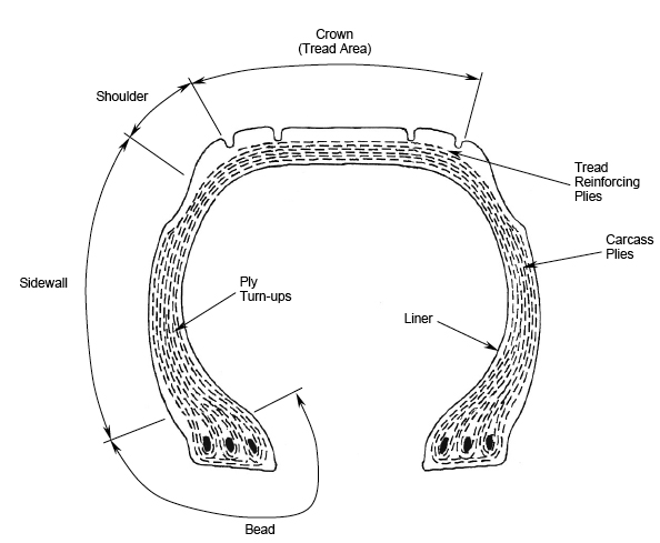
Five of the failed tyres were examined by the ATSB and by the tyre manufacturer in the United Kingdom (UK). The ATSB performed a visual examination and took fibre samples for detailed laboratory examinations, prior to shipping the tyres to the manufacturer. The tyre manufacturer examined the tyres under the supervision of a representative from the UK Air Accidents Investigation Branch (AAIB). A description of the tyre section components is contained in Figure 2.
Figure 2: Tyre section components
Examination by the ATSB
All tyre failures were similar in respect to the manner of casing break-up, with all presenting transverse ruptures along the sidewall ply axes. The stripping and loss of the tread from the tyre crown was limited to the two tyres that had failed at higher rotational speeds (landing and take-off) and was attributable to the effects of centrifugal forces on the tread belts as fracture and tearing progressed across the tyre crown. Bulk tread separation was not evident on the three tyres that had failed at lower (taxi) speeds.
Examination of the sampled fibres showed a combination of failure modes, attributable to tensile overload and possible cyclic loads stemming from structural flexure.
The failures were all consistent with the effects of a progressive failure and breakdown within the sidewall structure of the tyres. There was no evidence of the involvement of individual events such as foreign object impact, wheel skidding, or similar damage.
Examination by the tyre manufacturer
The tyre manufacturer's examinations found that the five tyres had failed in a similar manner. The conclusion made for each of the items examined was:
Cyclic fatigue in the inner ply turn-ups 3, leading to casing break-up, fracturing of the inner liner construction, ply separation and a localised sidewall rupture along the bias angle of the cord layers.
The tyre manufacturer also indicated that the fatigue in the inner ply turn-ups was due to cyclic flexing of the inner plies, which created a local looseness and reduction in strength. This led to a small fracture in the inner liner, resulting in a slow loss of pressure. The rate of pressure loss increased as the fracture in the inner liner grew, until it reached a point where, when combined with the operational loads, exceeded the venting capacity 4 of the casing and a rupture occurred.
A review of the original manufacture records for each of the tyres indicated that all had been manufactured from the correct material that were checked and passed laboratory sample testing. The destructive examination confirmed that the tyres were constructed to the approved design and process specifications.
Due to the extent and severity of the fatigue damage in the sidewall, and the low number of landing cycles accumulated by some of the failed tyres since the last retread, the manufacturer considered that the damage was possibly present, to some degree, during the last retreading process.
Approved tyres
At the time of the failures there were three tyre manufacturers approved to produce H44.5x16.5-21 28 PR tyres for the Boeing 737-800 series aircraft. A review of the specifications found that all three complied with the requirements of FAA Technical Standard Order TSO-C62d. The only notable difference between the brands was the average weight. The average weight for the tyres was 85.7 kg, 90 kg and 93 kg. The failed tyres were from the brand having the higher average weight.
TSO-C62d prescribed the minimum performance standard that aircraft tyres must meet to be identified with the applicable TSO marking. This performance standard included an overpressure and a dynamometer test 5. The TSO also dealt with changes to the tyre design with the following statement:
7.0 Requalification tests. A tire shall be requalified unless it is shown that changes in materials, tire design, or manufacturing processes could not affect performance. Changes in material, tire design, or manufacture processes that affect performance or changes in number or location of tread ribs and grooves or increases in skid depth, made subsequent to the tire qualification, must be substantiated by dynamometer tests in accordance with paragraph 6.0.
Retreading of tyres
Operational experience has shown that the tread of an aircraft tyre wears away at a much higher rate than the basic casing of the tyre and can be safely replaced multiple times before the casing reaches its service limits. As with all aircraft components, a controlled and regulated process was required to retread tyres. The FAA required a retread facility to have an approved process to both qualify tyres for retread, and for physically performing the retread. In 1982, to assist retread facilities in producing a process specification, the FAA released guidance material in the form of Advisory Circular AC 145-4.
In 1985, the Australian Civil Aviation Authority (the predecessor to the Civil Aviation Safety Authority, CASA) mandated the use of the guidance material in FAA AC 145-4 for the retreading of aircraft tyres, through the release of Airworthiness Directive AD/WHE/3 Amendment 1. The Australian retread facility responsible for the retreading of the occurrence tyres had a process specification approved by CASA that corresponded to AC 145-4.
Retread qualification requirements
For the speed rating 6 of the occurrence tyres, AC 145-4 required that the retread process specification included overpressure and dynamometer testing 7. Although not clearly stated in AC 145-4, the FAA and CASA have accepted that the retread process for a tyre of a particular size, speed rating and load rating shall be qualified by overpressure and dynamometer testing to R1 (first retread) level. To qualify for higher R-levels, the retreader need only perform a set of ply adhesion tests to check the strength of the rubber bond.
For bias-ply tyres 8, the FAA and CASA have also accepted that the overpressure and dynamic testing need only be carried out on one brand representing the size, speed rating and load rating, as 'Many years of evolution have resulted in a nylon bias tire having a casing structure that is essentially the same, irrespective of the manufacturer'. The tyres that were the subject of this investigation had not come from the brand of tyre that had been used in the qualification testing for this tyre range. The ATSB has had no reports of the observed type of failure in the brand used to qualify the retread process for the H44.5x16.5-21 28 PR tyre on the 737-800 series aircraft.
The retread facility noted some small differences to the profile between the subject brand and the other brands approved for use on 737 series aircraft.
Retread process
During retreading, before any physical work was carried out, the casing was subjected to a non-destructive inspection (NDI) process to determine if it was suitable for retread. The NDI process consisted of visual, shearography, and casing leak inspections. The visual inspection was a check by a trained technician to determine if there was any obvious damage in the surface of the tyre casing. The technician assessed any damage found to determine if it was within the limits allowed for the tyre, or if it was suitable for repair.
The shearography was a computer-based inspection system that compared the tyre under atmospheric pressure and a reduced pressure to determine if there were any separations within the ply structure. Tyres with separations exceeding preset limitations were rejected and destroyed. At the time the occurrence tyres were retreaded, only a shoulder-to-shoulder (crown area) shearography inspection was carried out. However, radial ply tyres 9 required a bead-to-bead (which included sidewalls) shearography inspection.
The final check was a casing leak check. Pressurised air was injected into the casing plies and soapy water sprayed over the tyre. Any leaks found were either accepted, or repaired if they were within the allowable limits, or the tyre was rejected and destroyed. After successful completion of all tests, the facility carried out the physical retreading process. A visual and dimensional check completed the retread process. Since the facility had been operating the shearography equipment (early 2004), they have included an additional, post-retread, shearography.
A review of the process documentation for each of the tyres examined found that all applicable inspections had been certified as having been completed before the tyre was released for service.
The area of the sidewall where the fatigue occurred was not subject to the pre- or post-retread shearography inspection on any of the tyres examined, nor was it required by their approved process specification.
Aircraft tyre maintenance
A review of the tyre pressure maintenance practices found that once fitted to the aircraft, the tyres were subject to a condition and inflation pressure check as part of the daily inspection. However, except for a layover in excess of 4 hours, there was no requirement to examine the tyres in detail on a normal turn-around pre-flight check. In that instance, only a condition check was required.
The operator with the five failures had a fleet of 45 737-700 and -800 series aircraft, including low, medium and high gross weight variants of each model. Each of the variants in the fleet (five in total) had their own nominal pressure requirements of 190, 200 or 205 psig 10 and were all listed on the same daily check Task Card. The Boeing Maintenance Manual inflation pressure check required that 'all tyres on the same gear are inflated to the selected nominal service pressure +/-5 psig'. The operator's Task Card did not present this range, but did contain the statement 'NOTE: If any tyre is below the nominal pressure by more than 5%, review the Aircraft Maintenance Manual for further requirements.' The Aircraft Maintenance Manual required that if the tyre pressure was 5% to 10% below the nominal service pressure, the tyre was to be reinflated to the nominal service pressure then checked again 24 hours later. If the tyre pressure was again more than 5% below the nominal service pressure, it was to be removed. If the tyre was found at any stage to be more than 10% below the nominal service pressure, it was to be removed from the aircraft immediately.
A review of a small sample of the operator's Maintenance Discrepancy Reports indicated that some of the engineers that checked tyre pressures had reinflated the tyres to 200 psig (the lower limit for the aircraft model), rather than the nominal service pressure of 205 psig. On one occasion, a tyre was found to be 180 psig, which is 12% below the nominal service pressure of 205 psig, but was reinflated to 200 psig and rechecked 24 hours later. The operator provided a revision of the Task Card that was reported to be applicable at the time of these Maintenance Discrepancy Reports that indicated that the nominal service pressure for the tyres was 200 psig. A revision of the task card in 2004, prior to the tyre failures, increased the nominal service pressure to 205 psig.
The operator carried out a survey of tyre pressures on a portion of their fleet over an eleven-day period and found that about 1% of tyres were 5% or more below the nominal service pressure. Of these low-pressure events, about one third were recorded in accordance with the operator's procedures.
Although both operators selected the same nominal main landing gear tyre pressure (in accordance with the Boeing maintenance instructions), the operator with the low number of failures had opted to avoid the lower end of the normal service pressure range and utilised the upper end of the pressure range (205 to 210 psig) for inflation pressure servicing.
Factors affecting tyre fatigue life
The heat generated by operation of aircraft tyres is a well-documented factor affecting tyre life. The heat in the tyres may be from an external source, such as the brakes, however the heat generated from flexing of the tyres is generally considered the primary source of temperature rise in aircraft tyres.
Studies carried out by various tyre manufacturers (presented in their tyre care and maintenance documentation) show that the effects of taxi speed, taxi distance and inflation pressure on the internally generated heat can be quite dramatic. The general effects are:
Increased taxi speed leads to increased tyre temperature
Increased taxi distance leads to increased tyre temperature
Decreased inflation pressure leads to increased tyre temperature.
The most significant increase in temperature was identified in the tyre bead/sidewall area.
The FAA provided guidance on the effects of turns on tyre temperature in AC 20-97B. The guidance to operators in this AC is:
Aircraft tires generate internal heating during normal operations. Under high aircraft loads (particularly under sideloading conditions), heat build-up is accelerated by excessive taxi speed and/or excessive taxi distances. Tire integrity and reliability may be compromised when a combination of these conditions occur.
Studies by tyre manufacturers have found that the performance of a tyre casing reduced by more than 50% when run continuously under-inflated by only 5%.
The casing is the body of the tyre consisting of the nylon structural cords embedded in a rubber compound.
H44.5x16.5-21 defines the size of the tyre. In this case, the tyre has an outer diameter of 44.5 inches, a width of 16.5 inches and fits on a 21-inch wheel rim. PR is the ply rating and is an indicator of the load capability of the tyre.
The inner ply turn-ups are the tail ends of the plies after they have wrapped around the bead and are located in the mid-sidewall region.
Tubeless aircraft tyres are designed with small vent holes in the outer sidewall. These vents release air pressure from the plies that has leaked or diffused through the inner liner.
The dynamometer test is a dynamic test that cycles a tyre through a range of operational speeds and loads to simulate a series of take-off and taxi cycles.
Because the tyres are designed to a performance specification for the tyre as a stand-alone item (TSO-C62d) and not to a particular aircraft, they are approved to a maximum speed and load. These limits are referred to as the 'speed rating' and 'load rating'.
AC 145-4 had additional qualification requirements for tyres with a speed rating above 160 mph.
Bias-ply tyres are also known as cross ply tyres. They are constructed from layers of rubber-coated nylon ply cords that extend around the beads and are oriented at alternating angles to the tread centreline.
Radial ply tyres are constructed from nylon and rubber cords, however, the cords are oriented differently to bias ply tyres. A set of cords run from one bead, across the crown and to the opposite bead. Another set of cords lie around the circumference of the tyre under the tread area.
The indicator reading, in pounds per square inch, showing the amount by which the tyre pressure exceeds atmospheric pressure.
ANALYSIS
Tyre failure mechanism and detection during maintenance and retread
Each of the tyres examined sustained a casing break-up event as a result of fatigue damage in the sidewall of the tyre. These failures occurred at a similar retread level (R4 and R5), but occurred well before the tread was due for replacement.
Aircraft tyres of this type had several operational measures to prevent premature failure. These included non-destructive inspection (NDI) during the retread process, inflation pressure maintenance, and aircraft weight and speed limitations.
Examination of the failed tyres found that the fatigue damage was quite extensive and was considered to be possibly present at the last retread. Because the shoulder-to-shoulder NDI used by the tyre retread facility was limited to the crown (tread area) of the tyre, it could not detect damage in the sidewall unless the extent of the damage breached the inner or outer surface of the tyre resulting in a leak. The NDI technique utilised by the retread facility was physically capable of inspecting the sidewall of the tyres, but neither the Civil Aviation Safety Authority (CASA) nor the Federal Aviation Administration (FAA) required sidewall inspection for bias-ply tyres.
Diffusion of the air through the inner liner of tubeless aircraft tyres resulted in the slow loss of pressure. Thus, it is vitally important to regularly check and maintain the tyre inflation pressures. The normal practice was a daily check on cold loaded tyres. This not only ensured that the tyres were operated in the correct pressure range but also allowed maintenance engineers to determine if a tyre was leaking at an abnormal rate.
An excessive leakage rate is a strong indication of imminent tyre failure and so it is critical that it is identified as soon as possible. The survey conducted by the operator indicated that only about one third of the low-pressure events were being recorded by the engineers. For those events that were not recorded, the only way to identify a 'leaker' (a tyre with pressure leakage in excess of the normal limits) was for a maintenance engineer to remember that the same tyre on the same aircraft was topped up on the previous day. As the operator had 45 aircraft, each with six tyres (four main and two nose) and operated from different ports around Australia, the detection of a 'leaker' was very unlikely.
The maintenance Task Card used by the operator during the daily check listed procedures for all of the 737 variants in their fleet. This was particularly evident for the tyre inflation checks where there were three possible nominal inflation pressures. This Task Card did not directly indicate the inflation pressure range for each aircraft variant but contained a note to refer to the Aircraft Maintenance Manual (AMM) if the pressure was below nominal by more than 5%. Although the abbreviated data on the Task Card provided the correct nominal pressure, it left the appropriate inflation pressure range open to some level of interpretation and possible confusion, as the limit for the inflation pressure in the AMM was the nominal ±5 psig, but the special maintenance procedures started at 5% (i.e. 10 psig) below the nominal pressure.
Until 2004, when the task card had the tyre nominal service pressure increased from 200 psig to 205 psig, the tyres had been operated at or below the lower limit of the normal service pressure range for extended periods. Under-inflation is a well-known factor in the development of fatigue in the sidewall of tyres resulting in reduced life performance.
The examination of the incident flight data did not show any single event that would have resulted in the failure. However, a review of the taxi speed data from two aircraft that had tyre failures, indicated that they were occasionally turned at speeds approaching, or exceeding, that recommended by the aircraft manufacturer. Considering the examination of the failed tyres and the analysis presented above, the damage to the tyres was not due to a single event, but an accumulation of damage during normal operations. The effect of turning at taxi speeds above that recommended by the manufacturer would further reduce the life expectancy of the tyre casing.
Certification of tyres and qualification for retread
The basic design standard for the tyres (FAA TSO-C62d) required requalification for a tread design change. This applied to each manufacturer. If a manufacturer changed their basic tread design, such that it was the same as a retread package, they would be required to retest to show compliance with the TSO. However, the practice for retread qualification accepted by both CASA and the FAA, required only one brand of tyre to be fully tested (overpressure and dynamometer). This testing may verify the retread package but does not capture the effect that the tread design, which may be different to the original tread design on the tyre, has on the performance of the casing of the non-tested brands.
Because the tyres were originally approved to Technical Standard Order TSO-C62d and had lasted for more than three retread lives, it was clear that there was no immediate weakness inherent in the original tyre design. As the aircraft type was fitted with several tyre brands, but only developed similar fatigue flaws in one brand, it appears that there were performance differences between the brands that the retread qualification testing of a single brand at R1 could not identify. There was no apparent compliance substantiation for the untested brands to the original design standard (i.e. TSO-C62), other than historical acceptance of similarities in the construction of bias-ply tyres.
SIGNIFICANT FACTORS
Flexing of the tyre sidewalls in operation resulted in fatigue damage in the inner casing plies.
The fatigue damage was possibly present at the last retread process but was not detected by the non-destructive inspection used in the process.
The fatigue in the plies allowed cracks to develop and grow in the inner liner, allowing high-pressure air to leak into the casing.
Maintenance crews did not detect an increase in the rate of pressure loss in the days leading up to the tyre failure.
The pressure leakage into the casing increased to the point that exceeded the capacity of the in-built venting and combined with operational loads, resulted in the failure of the tyre structure.
SAFETY ACTION
Australian Transport Safety Bureau
On 23 December 2004 the Australian Transport Safety Bureau issued safety recommendation R20040093. That recommendation stated:
The Australian Transport Safety Bureau recommends that Australian operators of Boeing 737-800 series aircraft review the practice of fitting retread tyres of R4 (fourth retread) or above, until their serviceability limitations can be identified.
In response to the safety recommendation, the ATSB was advised that the following actions were taken:
The operator of VH-VOH limited their in-service retread level to R3 on the 737-800 series fleet.
The other operator with 737-800 series aircraft performed a visual inspection of all in-service tyres and instigated a more stringent inspection of the tyres by maintenance and flight crews as part of the pre-flight checks.
The retread facility limited the maximum retread level for the H44.5x16.5-21 28 PR tyre to R3.
Aircraft manufacturer
The aircraft manufacturer noted a worldwide increase in 737 tyre failures, particularly in the 737NG (600, 700, 800, 900 and BBJ series). As a result, they conducted a study of the failures and released a Flight Team Digest in January 2005. Although their study found that no particular root cause for the failures was apparent, they were able to make some recommendations to improve the operation of the tyres. These recommendations included:
Inflate tires to the high end of the allowable ranges shown in AMM [Aircraft Maintenance Manual] 12-15-51. This reduces the sidewall deflection of the tire and therefore reduces the heat generated by the tire.
It is important to check inflation pressures frequently.
If a tire is identified as a leaker (as evidenced by two successive pressure checks where pressure is more than 5% low), it should be removed from the airplane immediately. Note that tires which are leaking gas through their inner-liner pose an imminent threat of a tread loss.
Operators should require that their retreaders perform the more complete bead-to-bead NDT checks (holography/shearography) on their tires as opposed to just checking the crown area. This appears to be especially important on 737NG tire sizes and is most critical when the tires reach high retread levels.
On 28 June 2005, the Boeing Commercial Airplane Company released Service Letter 737-SL-32-128-A 'Tire Retreading Recommendations' to 737-600/-700/-800/-900/BBJ operators. This Service Letter provided guidance on retreading NDI, retread limits and frequent and thorough pressure checks.
Operator of VH-VOH
On 1 June 2005, the aircraft operator released a General Engineering Notice (GEN) regarding tyre pressure checking and discrepancy recording. This GEN was associated with a change to the daily Task Card and provided more detailed guidance on the pressure maintenance of the tyres in the fleet and actions to be taken when a tyre pressure is found to be low. The GEN and daily Task Card included the following improvements:
Tyres are to be maintained in the upper end of the pressure range (i.e. nominal pressure +5/-0 psi).
Any tyre requiring a pressure top-up during the daily check is to be recorded in the Flight Technical Log (with pre- and post-inflation pressures) and the pressure re-checked on the next daily check.
The allowable pressure range (+5/-0 psi) has been listed with the nominal pressure for each aircraft variant in the fleet.
Expanded maintenance actions from the AMM for under-inflated tyres.
A note to ensure that the gauge used to check pressures is within calibration prior to use.
Tyre retread facility
On 9 September 2005, the Australian tyre retread facility included in their CASA approved Process Specification, bead-to-bead shearography inspections on all 737NG main gear tyres of retread level R3, and above.
United States Federal Aviation Administration
On 9 March 2006, the United States Federal Aviation Administration advised the Australian Transport Safety Bureau that they are currently reviewing and revising Technical Standard Order TSO-C62 and Advisory Circular AC 145-4. The changes to AC 145-4 are to include the recommendation for a reliability program and the increased use of shearography at increasing retread levels.
Summary
On 19 December 2004, a Boeing Company 737-86N aircraft, registered VH-VOH, was being operated on a scheduled passenger flight from Melbourne, Victoria to Canberra, ACT. At about 1655 Eastern Daylight-saving Time, while landing on runway 35, the right inboard main landing gear tyre failed.
In December 2004, the Australian Transport Safety Bureau (ATSB) noted an increase in the rate of tyre failures on Boeing 737 aircraft in Australia. It was noted that all of the failed tyres were at retread level (the number of times it had been retreaded) 4 and 5. The ATSB investigated the VH-VOH tyre failure in conjunction with these other recent failures.
Examination by the ATSB and the tyre manufacturer found that all the tyres had failed by fatigue in the sidewall. That fatigue was a result of cyclic flexing of the sidewall and was possibly present to some degree, but not detected, at the last retread.
Aircraft tyres of this type had several operational measures to prevent premature failure. Those included non-destructive inspection during the retread process, inflation pressure maintenance, and aircraft weight and speed limitations. The ATSB found that changes could be made by the aircraft operator and retread facility to improve the pressure maintenance and inspections during retread.
As a result of this investigation, safety improvements have been made by the aircraft manufacturer, aircraft operator and tyre retread facility to improve the life and reliability of the retreaded tyres. The United States Federal Aviation Administration is reviewing the certification requirements for the tyres and retread packages to include improved reliability programs.
The Australian Transport Safety Bureau did not conduct an on-scene investigation of this occurrence. The report presented below was derived from information supplied to the Bureau.
The pilot of the Cessna 210 aircraft, registered VH-UPN, reported that during the landing roll at Cockatoo Island, Western Australia, the wheel separated from the nose landing gear strut. The aircraft nosed-over and came to rest inverted. All occupants evacuated the aircraft without injury.
The operator examined the aircraft and found that the self-locking nut and through bolt for the nose landing gear wheel axle had separated from the nose landing gear, either prior to, or during, the take-off at Broome. The bolt and a washer were subsequently found on the runway at Broome. During the landing, the wheel became loose when the axle moved from the landing gear forks.
As a result of this occurrence, the operator has initiated an immediate inspection of its aircraft to ensure that only new through bolt retaining nuts are installed.