During the take-off run on runway 34 the first officer, who was flying the aircraft, called "failure" at approximately 120 knots. This was below V1, and the captain rejected the take-off. The Master Caution Air Conditioning lights were illuminated. The auxiliary power unit bleed air was supplying the left pack which was running in high mode. The pack tripped off as a result of high temperatures.
Autobrake was used in the rejected take-off selection and operated until down to a slow speed in the deceleration. The outboard left main wheel tyre deflated due to overheating. Both left main gear wheels and the left outboard brake unit were subsequently changed. Take-off should not be rejected from high speed for a Master Caution. However, when the first officer responded by calling "failure" the captain was obliged to reject the take-off.
Significant Factors
1. Master Caution Air Conditioning lights illuminated during the take-off roll.
2. The first officer incorrectly called "failure" for the caution light illumination.
3. The captain was obliged to reject the take off on the basis of the first officers call.
As the aircraft became airborne at Adelaide Airport, air traffic controllers observed a tread separating from a main landing gear tyre.
The pilot was advised and confirmed an abnormal landing gear indication. Most of the tread of a main gear tyre was found on the runway and emergency services were placed on full alert.
The aircraft was operated clear of the circuit to reduce landing weight and to allow emergency services to be made ready. Later, after an inspection fly-past was carried out, the aircraft landed safely.
There have been other tread losses from the same type of re-treaded tyre. As a result, the operator has reduced the number of times this type of tyre will be re-treaded and has also stopped the purchase of this type of tyre.
During the landing roll the right wheel brake failed to function. The pilot was unable to maintain directional control, resulting in a ground loop, during which slight damage to the left landing gear strut and right wingtip occurred.
Air in the right brake line rendered the right brake ineffective. It was not determined how the air was admitted to the system as no maintenance had been performed on the system since the aircraft had been delivered from the factory.
On selecting the landing gear up after take-off, the pilot reported hearing an unusual noise from the nose gear area. Cockpit gear position indicators did not illuminate and the nose gear mechanical indicator showed the gear leg to be in the three-quarter down position. The position of the landing gear was checked from the ground on arrival overhead the destination and the observer advised the pilot that the nose gear appeared to be trailing, and the main gear legs did not appear to be fully extended.
The pilot elected to divert to Weipa to avail himself of emergency services at that location. The aircraft was subsequently landed with the landing gear retracted. All the occupants evacuated the aircraft uninjured.
Subsequent inspection of the aircraft, by a company engineer, found that all three legs of the landing gear were in the up position. The nose gear actuator rod-end fitting was broken (the failure of the rod-end probably caused the noise heard by the pilot on gear retraction). The gear was cycled several times using both the normal and emergency systems, but no fault was found with the main gear or the position indicators when the gear lever and gear position were the same.
It would appear possible that the pilot inadvertently raised the gear using the emergency extension system prior to landing at Weipa.
Occurrence summary
Investigation number
199300238
Occurrence date
03/01/1993
Location
Weipa
State
Queensland
Report release date
23/08/1994
Report status
Final
Investigation type
Occurrence Investigation
Investigation status
Completed
Mode of transport
Aviation
Aviation occurrence category
Diversion/return, Landing gear/indication, Wheels up landing
On 1 February 2015, at about 0800 Western Standard Time (WST), a Cessna 210 aircraft, registered VH-SMP (SMP), departed from Kununurra Airport, Western Australia, for a scenic flight over King George falls with the pilot and five passengers on board.
The pilot returned to Kununurra after about 2 hours. During the approach, the pilot selected the landing gear selector to the down position. However, the green landing gear down indicator light did not illuminate. In addition, the landing gear pump continued to operate until the landing gear pump circuit breaker popped. The pilot observed that the right and left main landing gear appeared to be in the down and locked position. However, the pilot was unable to observe the nose landing gear.
As he was unable to verify the position of the nose landing gear, the pilot conducted a missed approach and held at about 1,500 ft above the ground level to investigate the reason for the malfunction. The pilot also broadcast on the common traffic advisory frequency (CTAF) his intentions and briefed the passengers.
The pilot selected the landing gear down and up another two times. However, in the down selection, there was no green landing gear down light and the landing gear pump continued to operate until the circuit breaker popped. The pilot inspected the landing gear down light globe and determined it was operational.
The pilot then used the ‘landing gear fails to extend’ and ‘manual gear extension’ checklists, and conducted a manual gear extension. The main landing gear was observed to be in the down position, but there was still no landing gear down green light.
The pilot contacted the operator first via a text message using a mobile phone, and then on the company radio frequency. After consulting with the operator, the pilot conducted a low-level pass over the runway to enable the operator to observe the landing gear position from the ground.
During the low-level pass, the operator observed the landing gear and reported to the pilot that the landing gear appeared to be in the down position. The operator told the pilot that it was likely to be an indication problem. The pilot returned SMP for a landing on runway 12 and briefed the passengers for the landing.
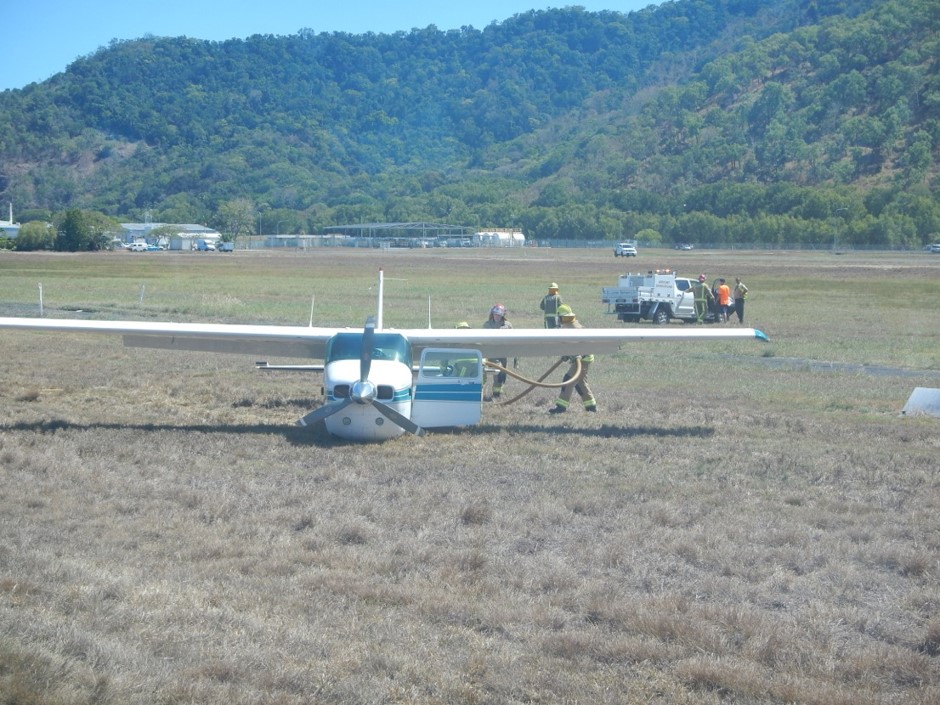
At about 1020, SMP landed, with the main landing gear wheels touching down first. The pilot held full back pressure on the elevator controls to hold the nose wheel off the runway for as long as possible. After about 100 m, the nose of the aircraft sank on to the runway. At this point, the nose wheel collapsed, the propeller struck the runway, and the aircraft came to a stop. Once the aircraft was stationary, the pilot completed the shutdown checks. The pilot and passengers then exited the aircraft through the two front doors.
The pilot and five passengers were uninjured. The aircraft sustained minor damage, including damage to the propeller, nose wheel, and engine cowling.
Pilot comment
The pilot reported that when the manual gear extension hand pump was used to pump the gear down, and was pumped until it could not be pumped further, it felt just like when the gear is in the down and locked position.
The pilot indicated that SMP last flew on 12 January 2015, about 3 weeks before the incident flight, and that there was no outstanding maintenance.
Owner investigation
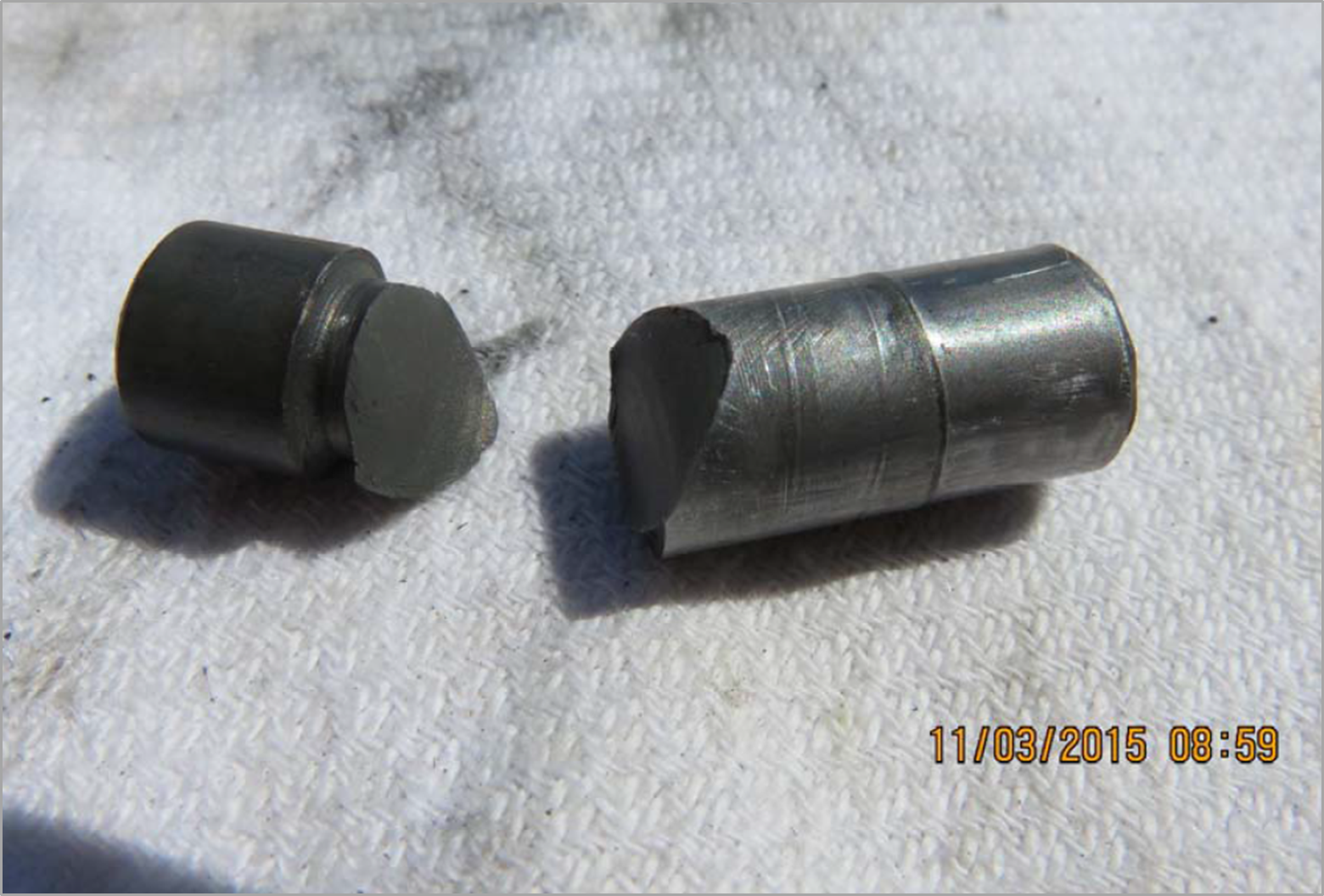
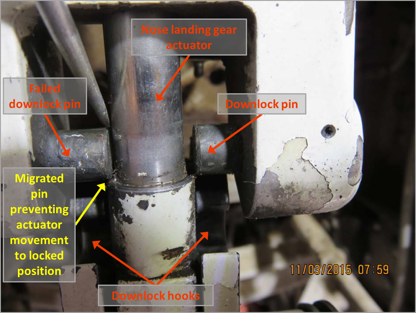
The owner of the aircraft conducted an investigation into the incident. As part of their investigation, they determined that one of the nose landing gear down lock pins had failed. The pin had failed in the area of the machined groove for the pin retention roll pin (Figure 1). The failed down lock pin migrated out and interfered with the nose landing gear actuator. This movement prevented the nose landing gear down lock mechanism from engaging in the down and locked position (Figure 2). The other down lock pin was serviceable.
Figure 1: Failed nose landing gear downlock pin
Source: Aircraft owner
Figure 2: SMP nose landing gear downlock assembly, showing the failed downlock pin preventing actuator movement to the locked position
Source: Aircraft owner, modified by the ATSB
Cessna Service Bulletin
Cessna Service Bulletin SEB95-20Nose Landing Gear Actuator Downlock Inspection dated 29 December 1995, recommended the inspection of the nose landing gear downlock actuator pins to determine the security of the pins.
Cessna had introduced the service bulletin as they had received reports that the nose landing gear actuator downlock pins had cracked and failed. It was found that the pins had failed at a circumferential groove that was used to secure the pin in the actuator bearing end. The service bulletin indicated that non-compliance could result in failure of the nose landing gear to lock in the down position and possibly collapse.
The recommended inspection was to be carried out initially within the next 200 hours operation or 12 months, whichever occurred first. Subsequent inspections at each landing gear retraction check were not to exceed 200 hours of operation thereafter. After the installation of the downlock actuator pin replacement, the repetitive inspection was not required.
Aircraft maintenance
SMP was manufactured in 1976 and, at the time of the incident, the aircraft had 9,965 hours total time in service. The aircraft was maintained under the Civil Aviation Safety Authority (CASA) maintenance schedule (Civil Aviation Regulations 1988 (CAR) Schedule 5). As the nose landing gear was inspected in accordance with Schedule 5, the operator reported that they did not need to comply with Cessna SEB95-20.
The periodic (100 hourly or 12-month) maintenance inspections were carried out in August 2014 at 9,871 hours total time in service (94 hours prior to the accident). This maintenance was conducted in accordance with the CASA maintenance schedule (Schedule 5). Schedule 5 did not include a specific inspection requirement to determine the security of the down lock pins.
NTSB investigation into similar failures
The US National Transport Safety Board (NTSB) investigated an accident involving a Cessna R182 aircraft, registered N6149S at Allegheny County Airport, West Mifflin, Pennsylvania on 18 May 2005 where the nose landing gear collapse during the landing.[1]
The NTSB determined that one of the downlock actuator pins (the same part number as SMP) on the nose landing gear actuator had failed and migrated out. The pin contacted the actuator arm piston, and prevented the full travel of the nose landing gear to the down and locked position. The NTSB examined the downlock pin and found that it had failed due to a fatigue crack. The investigation also found that the Cessna Service Bulletin SEB95-20Nose Landing Gear Actuator Downlock Pin Inspection had not been carried out. The investigation found over 30 other nose landing gear collapses that were attributed to the actuator down lock pins on similarly equipped Cessna aircraft.
The NTSB also investigated another similar accident involving a Cessna R182 aircraft, registered N5274S, at Ames Municipal Airport, Ames, Iowa, on 22 October 2006 where the nose landing gear collapse during the landing.[2]
The NTSB determined that one of the downlock actuator pins (the same part number as SMP) on the nose landing gear actuator assembly bearing end had failed and migrated out. The pin contacted the actuator arm piston, and prevented the full travel of the nose landing gear to the down and locked position. Both downlock pins were found to have fatigue cracks. Again, there was no evidence that Cessna Service Bulletin SEB95-20 had been complied with.
ATSB comment
On 12 September 2011, a flight control system event occurred involving Cessna 210N, VH-JHF, 48 km West of Bourke Airport, NSW. The ATSB investigation (AO-2011-115) found that reported elevator control input difficulties resulted from the fracture of the aircraft’s two horizontal stabiliser rear attachment brackets. The nature of the failures was typical of the damage sustained by aircraft as they age and move beyond the manufacturer's originally intended design life.
The investigation identified that maintaining class B aircraft in accordance with the Civil Aviation Safety Authority (CASA) maintenance schedule, without due regard to the manufacturer’s or other approved data, does not adequately provide for the continuing airworthiness of those aircraft.
As a result of the investigation the ATSB issued CASA a Safety Recommendation AO-2011-115-SR-050:
The Australian Transport Safety Bureau recommends that CASA proceed with its program of regulatory reform to ensure that all aircraft involved in general aviation operations are maintained using the most appropriate maintenance schedule for the aircraft type.
Safety action
Whether or not the ATSB identifies safety issues in the course of an investigation, relevant organisations may proactively initiate safety action in order to reduce their safety risk. The ATSB has been advised of the following proactive safety action in response to this occurrence.
Aircraft owner
As a result of this occurrence, the aircraft operator has advised the ATSB that the aircraft owner has taken the following safety actions:
Aircraft maintenance
Subsequent to the incident, the aircraft owner replaced the landing gear down lock pins with updated pins on two other aircraft that the owner is responsible for, and found no abnormalities with the removed pins or the nose landing gear actuator bearing ends.
Safety message
This accident highlights the importance of comprehensive, periodic maintenance inspections and the role manufactures continuing airworthiness instructions in maintaining ageing aircraft. As aircraft age, the original maintenance schedules may not be sufficient to ensure the aircraft’s ongoing safety. As a result of investigation report AO-2011-115 the ATSB encourages registration holders of class B aircraft to review their aircraft’s maintenance schedule to determine if it is the most appropriate for their aircraft and to ensure that it adequately provides for the continuing airworthiness of the aircraft.
In 2007, the ATSB released research report B20050205 - How Old is Too Old? The impact of ageing aircraft on aviation safety and is available from the ATSB website. The report found that some aircraft manufacturers have recognised that the original maintenance schedules may not be sufficient to ensure the aircraft’s (ongoing) safety. Those manufacturers have developed additional continuing airworthiness information. The report concluded that adequate maintenance of ageing aircraft requires the participation and ongoing cooperation of aircraft manufacturers, regulatory authorities, owners, operators, and maintainers.
In 2012, in recognition of the Australian general aviation aging aircraft fleet, CASA released a discussion paper Ageing Aircraft Management Plan (AAMP). The discussion paper makes the following relevant points:
As an aircraft ages up to and beyond its original design assumptions, the nominated maintenance program needs to be modified to take into account ageing issues. In particular, inspections of key areas or components not usually accessed.
CASA and Authorised Persons are obliged to take into account all relevant maintenance data or information pertinent to a particular aircraft type. This includes manufacturer’s data, Airworthiness Directives, Service Bulletins and other continuing airworthiness information.
CASA Maintenance Schedule 5 was originally conceived as a minimum schedule of maintenance activities, to be undertaken on a very limited range of relatively simple, ‘orphan’ aircraft
CASA Maintenance Schedule 5 was not originally intended to address ageing aircraft related issues. The literal application of this schedule on its own was not intended to replace the manufacturer’s instructions for continued airworthiness, where available.
The adequate maintenance of ageing aircraft requires the participation and ongoing cooperation of aircraft manufacturers, regulatory authorities, owners, operators, and maintainers.
The objective of a safety investigation is to enhance transport safety. This is done through:
identifying safety issues and facilitating safety action to address those issues
providing information about occurrences and their associated safety factors to facilitate learning within the transport industry.
It is not a function of the ATSB to apportion blame or provide a means for determining liability. At the same time, an investigation report must include factual material of sufficient weight to support the analysis and findings. At all times the ATSB endeavours to balance the use of material that could imply adverse comment with the need to properly explain what happened, and why, in a fair and unbiased manner. The ATSB does not investigate for the purpose of taking administrative, regulatory or criminal action.
Terminology
An explanation of terminology used in ATSB investigation reports is available here. This includes terms such as occurrence, contributing factor, other factor that increased risk, and safety issue.
Publishing information
Released in accordance with section 25 of the Transport Safety Investigation Act 2003
Ownership of intellectual property rights in this publication
Unless otherwise noted, copyright (and any other intellectual property rights, if any) in this report publication is owned by the Commonwealth of Australia.
Creative Commons licence
With the exception of the Coat of Arms, ATSB logo, and photos and graphics in which a third party holds copyright, this publication is licensed under a Creative Commons Attribution 3.0 Australia licence.
Creative Commons Attribution 3.0 Australia Licence is a standard form licence agreement that allows you to copy, distribute, transmit and adapt this publication provided that you attribute the work.
The ATSB’s preference is that you attribute this publication (and any material sourced from it) using the following wording: Source: Australian Transport Safety Bureau
Copyright in material obtained from other agencies, private individuals or organisations, belongs to those agencies, individuals or organisations. Where you wish to use their material, you will need to contact them directly.
On 11 November 2014, at about 1130 Eastern Standard Time (EST), a Cessna 210 aircraft, registered VH-JGA (JGA), departed from Cairns Airport, Queensland, for a scenic flight over Green Island and Arlington Reef with the pilot and four passengers on board.
After about half an hour of local flying, the pilot returned JGA to Cairns Airport. During the approach, at about 1,000 ft above ground level, the pilot selected the landing gear down, however, the green landing gear down indicator light did not illuminate. The pilot observed via an inspection mirror that the left main landing gear was just out of the landing gear recess and not in the down and locked position. The nose landing gear and right main landing gear appeared to be in the down position. The pilot advised the Cairns Tower air traffic controller that JGA would conduct a missed approach and requested a clearance to hold over the sea to determine the reason for the malfunction.
While holding over the sea, in the vicinity of Cairns Airport, at about 1,000 ft, the pilot conducted a landing gear emergency extension, but the left main landing gear still did not lock in the down position. The pilot contacted the operator and maintenance organisation via a mobile phone and conducted extensive troubleshooting, but was unable to get the left main landing gear to lock in the down position.
JGA was then returned to Cairns Airport and the pilot conducted a low level pass over the runway so that the landing gear could be observed. The nose landing gear and right main landing gear were observed to be in the down position, while the left main landing gear was observed to be out of the landing gear recess and only extended to about a 45 degree angle. The pilot elected to hold over the sea and reduce the amount of fuel on board, before conducting a landing. The pilot consulted with the operator and the maintenance organisation and decided to land on the grass area, abeam runway 33, with the landing gear retracted.
The pilot of JGA conducted two practice approaches to assess the aircraft configuration and landing area before beginning the approach for a wheels-up landing. The pilot extended the flaps to help slow the aircraft and, after turning onto a long final, briefed the passengers for the landing and instructed them to take up the brace position. Just prior to touchdown, the pilot turned off the master switch and moved the engine mixture control to the cut-off position. At about 1416, the aircraft landed on the fuselage underside on the grass area abeam runway 33 and came to a stop. The pilot and four passengers were uninjured and the aircraft was substantially damaged (Figure 1).
Figure 1: Damage to JGA
Source: Aircraft operator
Pilot comment
The pilot had flown the aircraft on a previous flight that day and had not noticed anything unusual. The pilot commented that there was sufficient fuel on board the aircraft so that there was time to investigate the malfunction and to plan and prepare for the landing.
When conducting the emergency extension, the nose and right main gear went straight to the down and locked position before the emergency extension hand pump was used. The hand pump had no effect on moving the left main landing gear.
Operator comment
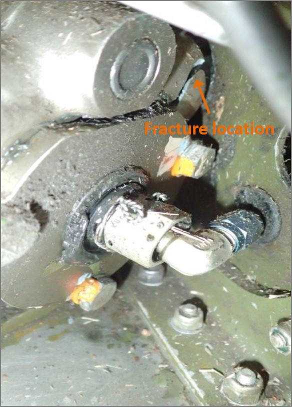
The operator conducted an investigation into the accident and determined that the housing of the left main landing gear had fractured (Figure 2), resulting in the gear not extending to the down and locked position. The operator reported that they conducted a visual inspection of the left and right main landing gear actuators for cracks and checked the tightness of the actuator mounting bolts at the periodic (100 hourly or 12-month) maintenance inspections with the actuator in-situ. The last inspection was conducted about 50 hours prior to the accident, with no defects found.
JGA was manufactured in 1981 and, at the time of the accident, the aircraft had about 12,882 hours total time in service. The aircraft was maintained under the Civil Aviation Safety Authority (CASA) maintenance schedule (Civil Aviation Regulations 1988 (CAR) Schedule 5). The left main landing gear was a non-lifed component and had been on the aircraft since new. There was no record that the actuator had been overhauled.
Figure 2: JGA left main landing gear actuator showing the fractured housing
Source: Aircraft operator
Cessna service manual
The Cessna 210 aircraft service manual contained a Supplemental Inspection Document (SID) 32-10-01 (temporary Revision Number 10 dated 1 August 2011) with a compliance date by 31 December 2013 that directly related to the removal and detailed inspection of the main landing gear retraction system. The inspection was to be carried out initially every 3,000 hours total time in service or 10 years whichever occurred first and repeated every 500 hours or 5 years whichever occurred first (JGA was manufactured in 1981 and had about 12,882 hours total time in service). The SID also required verification that Cessna Service Bulletin SEB01-2 Main Landing Gear Actuator Inspection has been accomplished. The Cessna 200 series SIDs were introduced in August 2011 and the CASA current compliance dates have been extended until 30 June 2015 for aerial work and charter operations and 31 December 2015 for private operations to allow for sufficient time for full compliance.
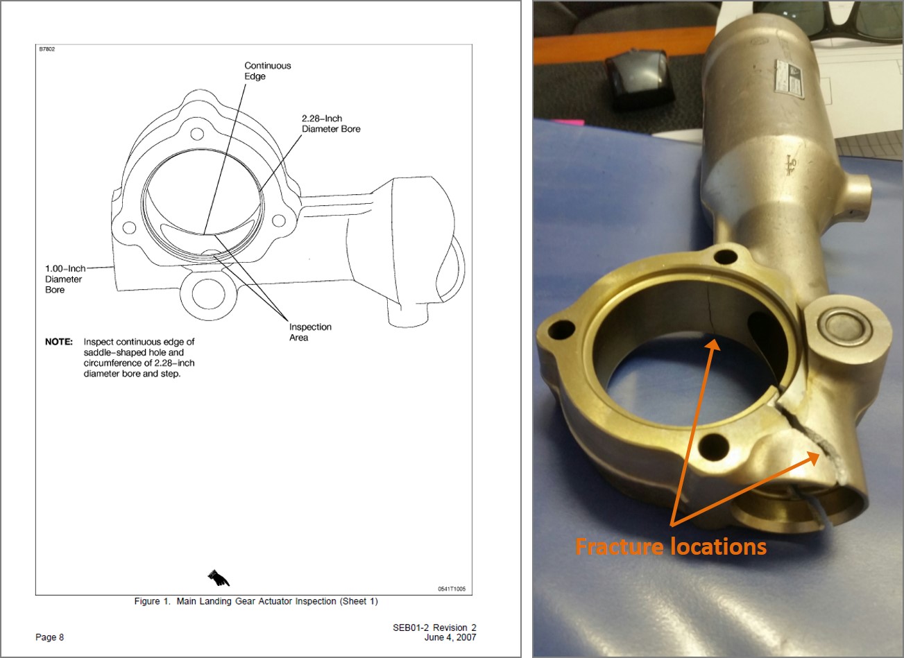
Cessna Service Bulletin SEB01-2 Main Landing Gear Actuator Inspection revision 2 dated 4 June 2007, required the inspection of the main landing gear actuators for the presence of cracks. Indicating that non-compliance with the service bulletin could result in failure of the main landing gear actuator. The service bulletin required the removal and disassembly of the main landing gear actuators and a fluorescent penetrant inspection of the actuator body to be carried out using black light and a magnifying glass to detect any cracks (Figure 3). The inspection was to be carried out initially every 3,000 hours total time in service within the next 100 hours operation and subsequent inspections every 500 hours total time in service thereafter.
Figure 3: Cessna Service Bulletin SEB01-2 Fracture located in JGA main main landing gear actuator inspection area landing gear actuator
Source: Cessna Aircraft operator
Aircraft maintenance
The aircraft operator reported that all Service Letters and Service Bulletins are reviewed by the maintenance organisation and implemented based on experience and at their request.
Information provided to the operator by the aircraft maintenance organisation was that the actuator fractured in what appeared to be one clean break and not a crack that slowly progressed, and that type of crack could occur in a sudden overload situation during the take-off when the landing gear is selected up and the wheels contact the ground. The maintenance organisation also recommended that the Service Bulletin requirements be carried out on aircraft that have exceeded 5,000 airframe hours.
The ATSB investigation AO-2011-115 Flight control system event involving Cessna 210N, VHJHF, 48 km West of Bourke Airport, NSW, 12 September 2011 found that reported elevator control input difficulties resulted directly from the fracture of the aircraft’s two horizontal stabiliser rear attachment brackets. The nature of the failures was typical of the damage sustained by aircraft as they age and move beyond the manufacturer's originally intended design life.
The investigation found at the time, that some aircraft registration holders believed that their aircraft was exempt from the manufacturer’s supplemental inspections, such as the Cessna SIDs when their aircraft was maintained using the CASA maintenance schedule (Civil Aviation Regulations 1988 (CAR) Schedule 5). While the CASA maintenance schedule did not make any specific reference to the incorporation of the manufacturer’s supplemental inspections, it was a CAR requirement that all aircraft be maintained in accordance with approved maintenance data that, by definition, included those inspections.
The ATSB investigation report AO-2011-115 is available at the ATSB website.
CASA issued Airworthiness Bulletin (AWB) 02-048 Compliance with Cessna Supplemental Inspection Documents (SIDs) on 7 April 2014 to clarify the requirement to comply with Cessna SIDs. The AWB comprised Aviation Ruling 01/2014, which stated that compliance with the Cessna SIDs was mandatory, irrespective of the category of operation or the elected maintenance schedule for the aircraft, be it:
CAR 42A Manufacturer’s Maintenance Schedule,
CAR 42B CASA Maintenance Schedule (Schedule 5), or
CAR 42C Approved System of Maintenance.
The AWB also stated that:
Significantly, the SIDs were developed on the assumption that the aircraft had been maintained using the Manufacturer’s Maintenance Schedule, or equivalent (including the incorporation of all applicable Service Bulletins), and do not necessarily take into account modifications or repairs made to the aircraft since manufacture. Therefore, all relevant Service Bulletins need to be incorporated to be in compliance with the SIDs inspections.
Since the accident involving JGA, CASA released Issue 2 to AWB 02-048, dated 10 April 2015, to clarify that those service bulletins listed in the SIDs are required to be incorporated and confirmed that, where specified in the SIDs, on-going inspections are also required to be complied with.
The AWB further stated that:
Therefore, all Service Bulletins that directly relate to the structural integrity of the aircraft need to be incorporated to be in compliance with the SIDs inspections. Please note that some Service Letters and other information referred to in the SIDs requirements were originally discretionary in nature. These documents are now considered mandatory if referred to as part of the SIDs inspections requirements in relation to [principal structural elements (PSEs)] PSEs.
US Federal Aviation Administration (FAA) Service Difficulty Reporting (SDR) database
A search of the US Federal Aviation Administration (FAA) Service Difficulty Reporting (SDR) database found about 65 entries dated from 1995 to 2014 of reported crack or cracks in the main landing gear actuator/s, in the same crack location as specified in the service bulletin or in that area and with the same part number as JGA’s actuator or one of the actuator part numbers listed in the service bulletin. Five entries had originated from Australia. About 20 reports resulted in an inflight incident and eight mentioned landing with the landing gear in the up position or without both main landing gear in the down position.
Although most reports indicated that the crack or cracks were located in the same area specified in the service bulletin, about 15 indicted they originated from one or more of the actuator attachment bolt holes. About 13 cracks had been located while carrying out the requirements of the service bulletin and the same number again were located while conducting a fleet inspection of the actuator. Several mentioned that this is an ongoing issue and suggested that the actuator be redesigned. One report mentioned a loose actuator attachment bolt, while two mentioned that the bolts were correctly torqued.
Although some entries lacked details, about seven specifically mentioned they were found during a scheduled inspection. One mentioned that the actuator had failed 25 hours after a 100 hourly inspection, which specifically checked the actuators externally for cracks. About three entries reported that the actuator had failed subsequently from conducting the requirements of the service bulletin. One reporter indicated that an inspection should be conducted on the actuator any time that the landing gear contacts the ground in other than the fully extended or fully retracted position.
Safety action
Whether or not the ATSB identifies safety issues in the course of an investigation, relevant organisations may proactively initiate safety action in order to reduce their safety risk. The ATSB has been advised of the following proactive safety action in response to this occurrence.
Operator
As a result of this occurrence, the aircraft operator has advised the ATSB that they are taking the following safety actions:
Maintenance action
The operator’s Cessna 210 aircraft fleet will undergo further examination to see if there is any evidence of other potential failures within the fleet.
Safety message
This accident highlights the importance of comprehensive, periodic maintenance inspections and the role of supplemental inspections in maintaining ageing aircraft. As aircraft age, the original maintenance schedules may not be sufficient to ensure the aircraft’s ongoing safety. It is important to review the aircraft’s maintenance schedule to ensure it is appropriate for the aircraft and that it adequately provides for the continuing airworthiness of the aircraft.
In 2007, the ATSB released research report B20050205 - How Old is Too Old? The impact of ageing aircraft on aviation safety. The report found that some aircraft manufacturers have recognised that the original maintenance schedules may not be sufficient to ensure the aircraft’s (ongoing) safety and have developed supplementary inspection programs (such as the Cessna SIDs); other aircraft do not have the same level of airworthiness support. The report concluded that adequate maintenance of ageing aircraft requires the participation and ongoing cooperation of aircraft manufacturers, regulatory authorities, owners, operators and maintainers.
In addition, further information is detailed in CASA’s Ageing Aircraft Management Plan (AAMP).
The objective of a safety investigation is to enhance transport safety. This is done through:
identifying safety issues and facilitating safety action to address those issues
providing information about occurrences and their associated safety factors to facilitate learning within the transport industry.
It is not a function of the ATSB to apportion blame or provide a means for determining liability. At the same time, an investigation report must include factual material of sufficient weight to support the analysis and findings. At all times the ATSB endeavours to balance the use of material that could imply adverse comment with the need to properly explain what happened, and why, in a fair and unbiased manner. The ATSB does not investigate for the purpose of taking administrative, regulatory or criminal action.
Terminology
An explanation of terminology used in ATSB investigation reports is available here. This includes terms such as occurrence, contributing factor, other factor that increased risk, and safety issue.
Publishing information
Released in accordance with section 25 of the Transport Safety Investigation Act 2003
Ownership of intellectual property rights in this publication
Unless otherwise noted, copyright (and any other intellectual property rights, if any) in this report publication is owned by the Commonwealth of Australia.
Creative Commons licence
With the exception of the Coat of Arms, ATSB logo, and photos and graphics in which a third party holds copyright, this publication is licensed under a Creative Commons Attribution 3.0 Australia licence.
Creative Commons Attribution 3.0 Australia Licence is a standard form licence agreement that allows you to copy, distribute, transmit and adapt this publication provided that you attribute the work.
The ATSB’s preference is that you attribute this publication (and any material sourced from it) using the following wording: Source: Australian Transport Safety Bureau
Copyright in material obtained from other agencies, private individuals or organisations, belongs to those agencies, individuals or organisations. Where you wish to use their material, you will need to contact them directly.
The pilot taxied the aircraft for departure, back tracking to the north-west end of the runway. While turning right to line up for take-off, the left main landing gear collapsed, allowing the left propeller to strike the ground, stopping the engine.
The eye bolt attaching the landing gear side brace strut to the spar fitting was found to have suffered a corrosion fatigue failure allowing the gear to collapse inwards, i.e. in the direction of retraction. As this did not effect the downlock latching mechanism or micro switch at the strut elbow joint, all three green gear down lights in the cockpit remained on.
The operator had previously experienced this problems with similar type aircraft, and as the bolt is difficult to see during inspections, he instigated a program to replace it with a modified type. This aircraft had only recently been acquired, and the bolts would have been replaced at the first service by the operator.
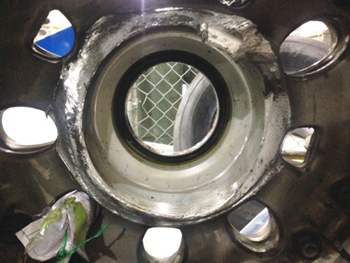
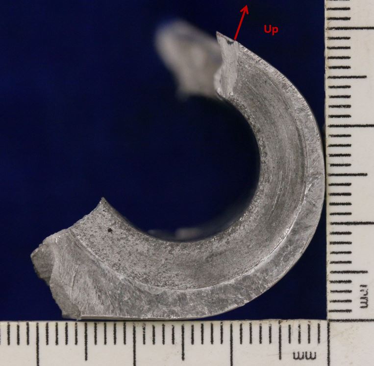
On 10 June 2014, a Boeing 737 aircraft, registered ZK-ZQB and operated by Jetconnect Limited landed at Sydney Airport, New South Wales. During taxiing, the crew felt a slight shuddering from around the main landing gear; they also observed that they required a higher-than-normal thrust to taxi the aircraft. At the crew’s request, personnel in the Air Traffic Control tower and a passing aircraft observed ZK-ZQB, but did not see anything abnormal. The crew then requested that Rescue and Fire Fighting Services conduct a close-up inspection. They advised the crew that pieces of metal had fallen onto the runway and that the right, outer main wheel was leaning over. After parking the aircraft, an examination by Licenced Aircraft Maintenance Engineers confirmed that the inboard wheel half-hub had fractured into several pieces and that the wheel bearings were intact.
Inboard wheel half remnant
Source: Aircraft operator
Wheel hub failure
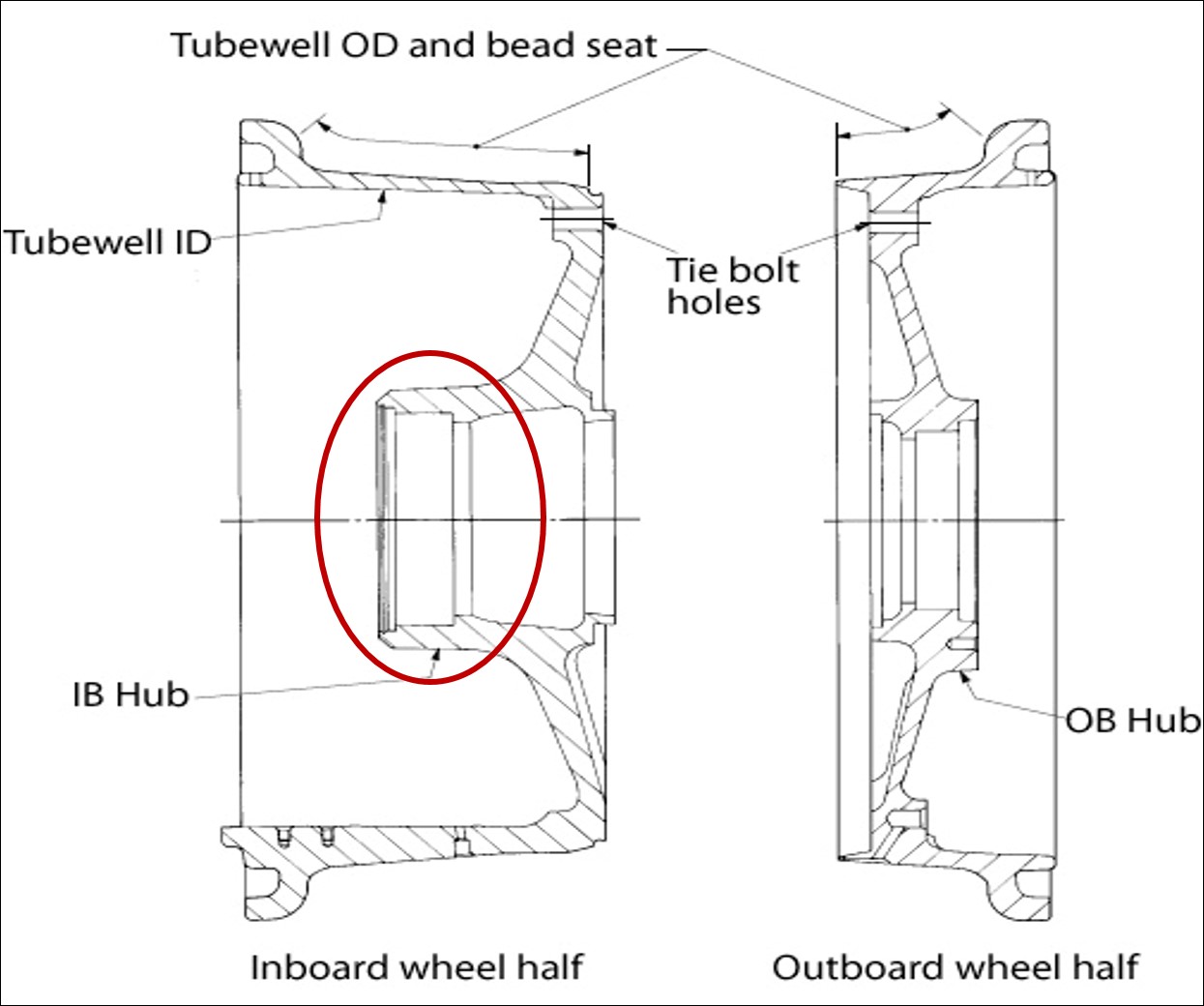
The wheel hub consisted of an inboard and outboard section (Figure 1).The inboard wheel half on ZK-ZQB was part number 2612462 and serial number B3902.
Figure 1: Schematic diagram of wheel hub with the failure location circled
Source: Honeywell
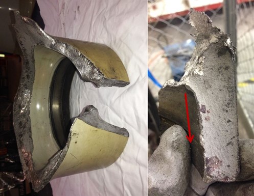
After removal of the bearing cup, the aircraft operator inspected the bore and reported that there was no sign of bearing cup rotation. A visual inspection of the fracture surfaces was then performed by the operator’s maintenance organisation that indicated the origin of the failure to most likely be in the area of the bearing bore radius (Figures 2a and b). However, that area had been damaged, following the final fracture. From the point of origin, a series of cracks grew both axially (Figure 2b) and circumferentially around the inboard hub (Figure 3). In the axial direction, chevrons on the fracture surface radiated from the radius area. Circumferential crack growth occurred partly by joining a series of smaller, tertiary cracks on the hub’s outer diameter. The surfaces of that circumferential crack showed the joining process as a series of ratchet marks. This earlier part of that fracture surface was burnished as the two faces of the crack had rubbed together over a period of time, obliterating some detail. The crack then became a singular front with beach marks, an indicator of fatigue cracking. The area of ultimate failure changed from fatigue to the more rapid, overload mode.
The wheel manufacturer also examined the failure. They concluded it was likely that the fatigue crack initiated in the stress-concentrated, transition region between the bearing bore wall and the circumferential radius. Ultrasonic testing of this area detected possible small fatigue cracks or origins.
Figures 2a and b: Fractured hub from the inboard wheel half and chevrons leading from the damaged, radius-area origin; the arrow shows the direction of crack growth from that area
Source: Aircraft operator
Figure 3: Secondary, circumferential crack showing, from left to right, the damaged origin area, ratchet marks/burnishing, beach marks and ultimate failure by overload
Source: Aircraft operator
Related manufacturer’s and operator’s service information
Due to previous failures of the wheel hub, service bulletins and requirements for inspection were issued by the aircraft and wheel manufacturers. These included a Boeing Service Letter,[1] which indicated that there was a known failure mode of the wheel hub, which was related to a loose or spinning bearing cup in the hub bore. As noted earlier, inspection of the bore, post-cup removal, found no indication of bearing cup rotation. The Boeing Fleet Team Digest[2] noted that failures could also occur from fatigue initiating in the bearing bore radius area (as was the case in ZK-ZQB); however, those failures had primarily occurred in the redesigned wheel hubs that superseded the 2612462 part number i.e. from PN 2615480.
In 2010, Boeing also issued a Special Attention Service Bulletin[3] covering 737 wheel failures. That bulletin recommended ultrasonic inspection, in accordance with the wheel manufacturer’s service bulletin[4], of relevant part and serial numbers, whenever a wheel was removed from the aircraft. For part number 2612462, the wheel manufacturer recommended non-destructive testing (NDT) at each overhaul interval. In ZQB’s case, this averaged approximately 180 landing cycles per interval. That inspection required[5] visual examination of each component, measurement of specific parts/areas and ultrasonic inspection of the hub outer diameter of both wheel halves to detect bearing-bore cracks at every tyre change and wheel overhaul. However, if the bearing cup had been removed, other NDT methods (eddy current, ultrasound or fluorescent penetrant inspection (FPI)) were to be used to inspect the bearing bore’s internal diameter and corner radius. The component maintenance manual also noted that visual inspection of the wheel halves was to investigate for damage to paint or corrosion-protection coatings, as stress concentrators in corrosion could also initiate fatigue cracking.
In summary, note that for PN 2615480, serial number (SN) B15418 and prior and SN H0483 and prior wheel halves, mandatory annual NDT inspection was required. For PN 2612462 and PN 2615480, SN B15418 and above and SN H0483 and above wheel halves, compliance with the NDT recommendation was optional.
Maintenance
Examination of the maintenance records, from the 15 months before the inboard wheel-half failure, found that the wheel manufacturer’s recommended inspections had been performed whenever the wheel had been removed from the aircraft. Although the March 2013 major service specified non-removal of the bearing cup and, consequently, ultrasonic inspection, all services since then used eddy current inspection. The wheel manufacturer’s service bulletin specified that such a test could only be done if the bearing cup and sleeve assembly had been removed. No discrepancies were reported for the visual, ultrasonic, eddy current and FPI methods used as part of these inspections. The most recent record that included landing cycle data (February 2014), noted that 84 cycles had occurred in the two months since the last service (December 2013) and that the total time since new (TSN)/ time since overhaul (TSO) hours were 22901/1803 respectively. In March 2013, a major service was carried out and the tie bolt hole radii were shot peened. This shot peening was restricted to this area and did not include the bearing bore radius.[6]
Safety action
The ATSB was advised by the aircraft operator that they are upgrading their fleet with carbon brakes from a different manufacturer. As a result, all current main wheel assemblies will be replaced with wheels from that manufacturer; hence, those wheels will have a different part number. The modification program of fitment with new wheels and brakes commenced in February 2015 and will be completed by the end of May 2015.
The objective of a safety investigation is to enhance transport safety. This is done through:
identifying safety issues and facilitating safety action to address those issues
providing information about occurrences and their associated safety factors to facilitate learning within the transport industry.
It is not a function of the ATSB to apportion blame or provide a means for determining liability. At the same time, an investigation report must include factual material of sufficient weight to support the analysis and findings. At all times the ATSB endeavours to balance the use of material that could imply adverse comment with the need to properly explain what happened, and why, in a fair and unbiased manner. The ATSB does not investigate for the purpose of taking administrative, regulatory or criminal action.
Terminology
An explanation of terminology used in ATSB investigation reports is available here. This includes terms such as occurrence, contributing factor, other factor that increased risk, and safety issue.
Publishing information
Released in accordance with section 25 of the Transport Safety Investigation Act 2003
Ownership of intellectual property rights in this publication
Unless otherwise noted, copyright (and any other intellectual property rights, if any) in this report publication is owned by the Commonwealth of Australia.
Creative Commons licence
With the exception of the Coat of Arms, ATSB logo, and photos and graphics in which a third party holds copyright, this publication is licensed under a Creative Commons Attribution 3.0 Australia licence.
Creative Commons Attribution 3.0 Australia Licence is a standard form licence agreement that allows you to copy, distribute, transmit and adapt this publication provided that you attribute the work.
The ATSB’s preference is that you attribute this publication (and any material sourced from it) using the following wording: Source: Australian Transport Safety Bureau
Copyright in material obtained from other agencies, private individuals or organisations, belongs to those agencies, individuals or organisations. Where you wish to use their material, you will need to contact them directly.
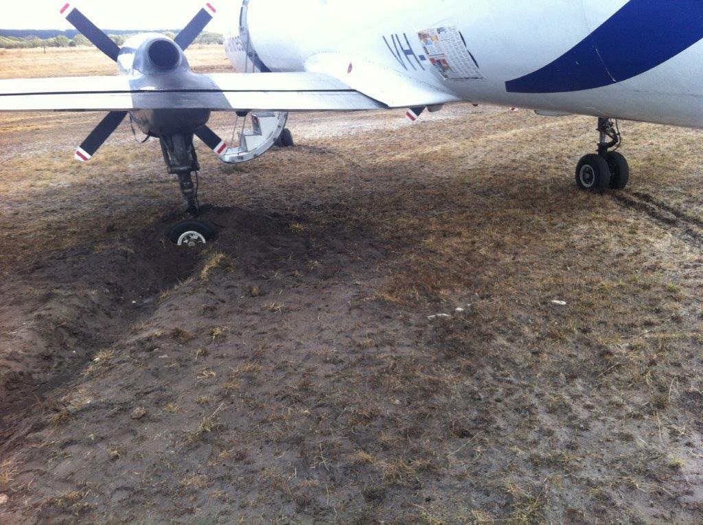
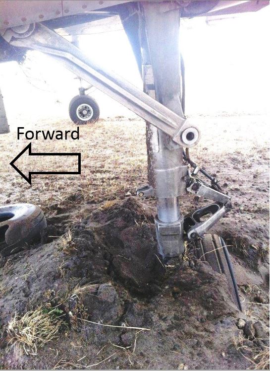
On 20 February 2014 at 1425 EDT, a Fairchild Industries Metro 23 aircraft, registered VH-UUB, was being operated on a charter flight from Avalon to Portland, Victoria with 10 passengers and two crew on board. Shortly after touch-down the torque link on the left, main landing gear (MLG) failed. The aircraft veered left as a result, and came to rest beside the runway. There were no injuries as a result of the occurrence.
What the ATSB found
The runway excursion resulted from failure of the lower torque link attachment lug on the left main landing gear’s yoke. This allowed the wheels to rotate through 90° with respect to the direction of aircraft travel and skid, producing a large braking effect on the left side. The flight crew were unable to counteract this and it resulted in the aircraft veering to the left and off the runway.
The failure of the lug on the yoke resulted from pre-existing cracks that had progressively grown until the part had insufficient strength to support normal landing loads. The cracks initiated principally from areas of pitting corrosion in the lug’s bore and were propagated by cyclic stresses imposed during operation.
The ATSB identified a safety issue whereby the maintenance and inspection program for the aircraft’s landing gear did not adequately provide for the detection of corrosion and cracking in the yoke lug bore.
What has been done as a result
The Civil Aviation Safety Authority (CASA) has released Airworthiness Bulletin AWB 32-023 to alert all Fairchild Swearingen Metro and Merlin operators of the need for detailed inspection of the internal bore of the landing gear torque link lugs for any signs of corrosion or wear outside of the manufacturer’s specified limits and to take appropriate action per the aircraft’s structural repair manual, where necessary.
In addition, the aircraft’s Type Certificate Holder has drafted service bulletins 226-32-083, 227-32-065, CC7-32-030 titled “inspection of Main Landing Yoke for Corrosion and/or Damage” that will significantly increase the effectiveness of maintenance inspections for the affected parts.
Safety message
This occurrence highlights the importance of developing and conducting appropriately detailed maintenance inspections on susceptible parts and assemblies.
UBB after veering off the runway
Source: airline operator
Findings
From the evidence available, the following findings are made with respect to the runway excursion involving a Fairchild Metro 23 aeroplane, registered VH-UUB, which occurred at Portland, Victoria on 20 February 2014. These findings should not be read as apportioning blame or liability to any particular organisation or individual.
Safety issues, or system problems, are highlighted in bold to emphasise their importance. A safety issue is an event or condition that increases safety risk and (a) can reasonably be regarded as having the potential to adversely affect the safety of future operations, and (b) is a characteristic of an organisation or a system, rather than a characteristic of a specific individual, or characteristic of an operating environment at a specific point in time.
Contributing factors
The runway excursion occurred as a result of fracture of the torque-link attachment lug on the aircraft’s left main landing gear yoke, which allowed those wheels to deviate from the normal direction of travel and cause asymmetrical braking forces that could not be countered by the flight crew.
The torque link-to-yoke attachment lug fractured under normal operational loads as a result of the initiation and propagation of fatigue cracks originating at areas of excessive wear and corrosion pitting on the lug bore.
The maintenance program for the aircraft’s landing gear did not adequately provide for the detection of corrosion and cracking in the yoke lug bore. [Safety issue]
Context
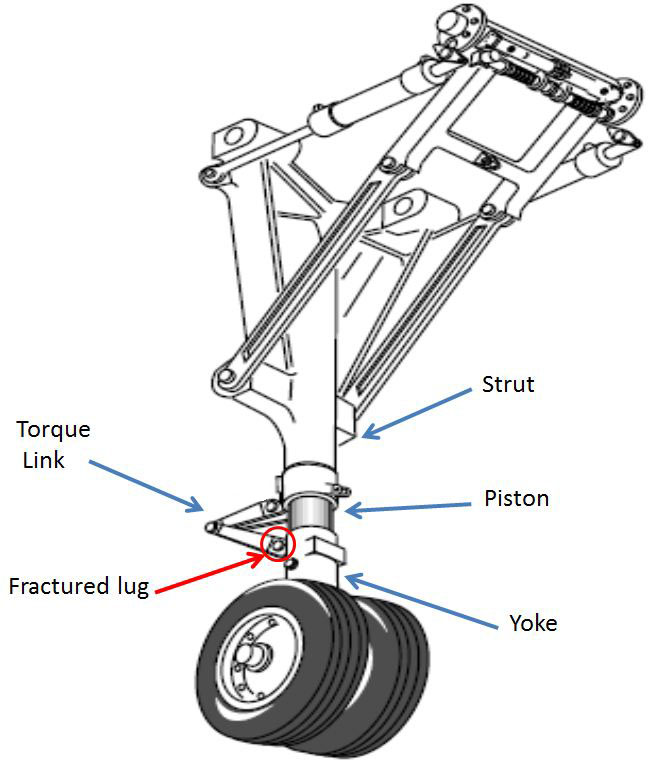
Main landing gear description
The main landing gear assembly is composed of a telescoping upper cylinder (strut), a piston assembly and, at the lower end, the yoke (Figure 3). A torque link assembly connects at lugs on the strut and the yoke, allowing compression of the assembly while preventing rotation of the yoke. In this occurrence, the lug on the yoke had fractured.
Yokes in the MLGs of earlier SA227 models were manufactured by Ozone Industries as part number (P/N) OAS5453005-5[3]. In later models, manufacture was by another landing gear vendor, Klune Industries, and started with the fabrication of the 27-series part numbers. The fractured yoke from VH-UUB was identified as P/N 2751505005, manufactured by Klune Industries.
Source: M7 Aerospace SA227 Maintenance Manual (Modified by ATSB)
Recorded information
The ATSB downloaded and analysed data from the aircraft’s Flight Data and Cockpit Voice Recorders (FDR & CVR, respectively). The data confirmed that following touchdown, the aircraft began veering to the left. Approximately 8 seconds later, the aircraft departed the runway. In addition, the following points were noted:
The vertical speed prior to landing was that of a normal approach.
Vertical decelerations recorded during the touch-down were not excessive.
The airspeed at touch-down was consistent with prior flights.
The aircraft was correctly configured for landing.
Component Examination
Lug Fracture
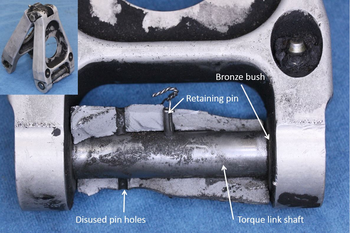
The aluminium torque link and yoke were assembled via a steel torque link shaft (TLS) that mated with bronze bushes in the lower link. It was secured with a single, stainless-steel retaining (spring) pin with stainless steel lockwire in its bore (Figure 4).
The fractured yoke contained four disused retaining pin holes (two each top and bottom) as a result of compliance with a service bulletin (SB) for installing a replacement TLS (CC7-32-012), released in 2002. The SB required drilling of a new pin hole in the lug to secure the replacement TLS and filling of the redundant holes with sealant. As examined, the disused holes in the fractured yoke were not sealed, but instead contained black corrosion/wear product. However, traces of sealant around some of the holes suggested that they had probably been filled at the time of service bulletin compliance.
Figure 4: Lower torque link attachment assembly with fractured lug segment in-situ
Source: ATSB
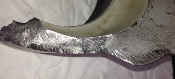
Significant corrosion pitting was evident in the bore of the lug and on the lug flanks, with concentrations around the four disused, spring pin holes (Figure 5). Fatigue crack progression (beach) marks were identified on the lug fracture surfaces with the crack origins located at areas of significant corrosion pitting and wear in the bore. The fatigue cracking progressed across most of the lug cross section before the remaining portion fractured by ductile overstress. The overstress areas were largely defined by a narrow region on the outside radius of the lug (furthest from the bore).
Detailed examination of the corrosion pits adjacent to the fracture surface found evidence of corrosion product as well as a series of crack progression marks radiating outwards from the edge of the corroded areas.
Figure 5: Yoke lug exhibiting corrosion pitting, wear in the bore and fatigue crack progression on the fracture surfaces (main crack origins arrowed)
Source: ATSB
Lug dimensions
The bronze bushes installed in the lower torque link had worn against the yoke’s lug flanks during normal operation such that, in the areas of greatest wear, the width of the lug was now 66.03mm (2.6”) which was 0.26mm (0.01”), below the minimum dimension of 2.61” (66.294mm) specified in the structural repair manual (Figure 5).
Material properties
The material properties were correct for the specified 7075-T73 aluminium alloy. Electrical resistivity testing showed that a majority of the chromic acid anodised coating, applied to the component during manufacture, had worn away, increasing the component’s susceptibility to corrosion and wear, particularly in an aqueous environment of metals dissimilar to aluminium.
Figure 6: Flank of the fractured yoke lug showing surface wear from mating bush
Source: ATSB
Yoke maintenance requirements
The Fairchild MLG yokes were maintained on condition and were not subject to any maximum service life restrictions. At the time of the occurrence, the SA227 Phase Inspection Manual (SA227 CC/DC Commuter Category, Rev 19, Sept 28, 2012) included requirements for inspection of the aircraft structure and components. The definitions section of the manual stated that;
A routine inspection – Visual inspection not requiring removal of access panels or fairings.
A detailed inspection – Detailed inspection requiring removal of access panels, doors, fairings, covers, upholstery and components for inspection.
The aircraft was maintained using a 6-phase inspection program with an interval of 900 hours; this included a detailed inspection of the main landing gear at a phase 3 inspection (450 hours) and a routine inspection at a phase 6 inspection (900 hours).
The phase inspection manual also included a section which included a list of requirements for the routine and detailed inspections. The detailed inspection included the requirement to inspect struts for damage, evidence of leakage, condition and security, and to inspect scissors and bushings for wear, condition and security. The manufacturer advised that in order to perform these inspections, the shaft attaching the scissor links to the yoke lug should be removed and the condition of the components checked, as well as the wear limits.
The most recent detailed (Phase 3) inspection was 436.5 hours prior to the occurrence, and a routine (Phase 6) inspection 37.3 hours prior to the occurrence. The operator’s inspection procedures followed the guidelines in the inspection manual and there was no record of the components being disassembled at either inspection. The operator advised that they performed a torque link freeplay inspection at the detailed inspection and if excessive freeplay was evident, then the components would be disassembled for further inspection.
In August and September 1995, Fairchild issued two service bulletins to cover six of the earlier SA227 models equipped with Ozone MLG & NLG (Nose Landing Gear) yokes. This was due to failures initiated by stress corrosion cracking and corrosion fatigue. In those occurrences, the failure origin was at the forging die parting (flash) line in the upper yoke area, where the piston was shrink-fitted. Both the Federal Aviation Administration and the Civil Aviation Safety Authority issued airworthiness directives a month later.
Other occurrences
On 10 June 2007, an SA227-DC, registered VH-HPE, sustained a left MLG yoke lug failure during post-landing taxiing at Tennant Creek Aerodrome. The ATSB did not investigate that occurrence, however a report provided to the ATSB indicated that the fracture similarly related to fatigue crack progression precipitated by wear, corrosion pitting and stress corrosion cracking in the yoke lug bore.
The Civil Aviation Safety Authority (CASA) were aware of four Australian-registered, SA227 MLG torque link lug failures, as well as cracking of a yoke lug, found during daily inspection, on a Canadian-registered aircraft.
The manufacturer advised they were aware of two cracked yoke lugs, which were found by the same Canadian operator in 2012. A failure analysis report for one of the failures showed similar cracking to that identified on UUB. The report stated that the failure occurred as a result of cracking that had initiated at multiple corrosion pits on the inner surface of the lug. In this case however, the cracking had propagated to the external surface, which allowed it to be identified during a daily maintenance inspection. The same Canadian operator also experienced a third failure in December 2015, which was identified by the flight crew after landing.
Sources of information used during the investigation included:
the aircraft’s type certificate holder
the aircraft operator
the Civil Aviation Safety Authority
the operating flight crew
the aircraft’s flight data recorders.
Submissions
Under Part 4, Division 2 (Investigation Reports), Section 26 of the Transport Safety Investigation Act 2003 (the Act), the Australian Transport Safety Bureau (ATSB) may provide a draft report, on a confidential basis, to any person whom the ATSB considers appropriate. Section 26 (1) (a) of the Act allows a person receiving a draft report to make submissions to the ATSB about the draft report.
A draft of this report was provided to the operator, the aircraft maintenance provider, M7 Aerospace and CASA.
Submissions were received from the operator, M7 Aerospace and CASA. The submissions were reviewed and where considered appropriate, the text of the report was amended accordingly.
The occurrence
On 20 February 2014, a Fairchild Industries SA227-DC ‘Metro 23’ aircraft, registered VH-UUB, had been flown from Avalon to Portland, Victoria on a charter flight. On board were two flight crew and 10 passengers. A normal approach was conducted and the aircraft touched down at 1425 EDT[1]. During the landing roll, the flight crew noted the aircraft began veering to the left. The flight crew attempted to counteract the movement, using rudder inputs, reverse thrust on the engines and the right brake, but the aircraft subsequently departed the runway at a speed of 75 to 80 knots and began to slide sideways. The left main landing gear (MLG) dug into the ground and the nose of the aircraft swung sharply to the left as it came to a stop. The flight crew shut the aircraft down and disembarked the passengers when it was safe to do so. There were no reported injuries as a result of the occurrence.
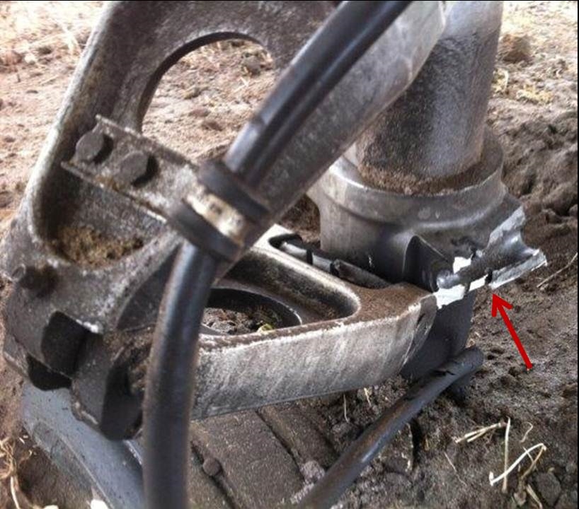
Subsequent inspection of the aircraft found that the torque link[2] had detached from a fractured lug on the lower section of the left MLG (arrowed in Figure 1b), allowing the wheel assembly to rotate through 90° w.r.t. the direction of aircraft travel. This resulted in skidding wheels, producing a significant braking effect on the left main gear and causing the aircraft to veer to left and depart the runway (Figure 2).
Figure 1: Damage to the left MLG
Source: Airline operator
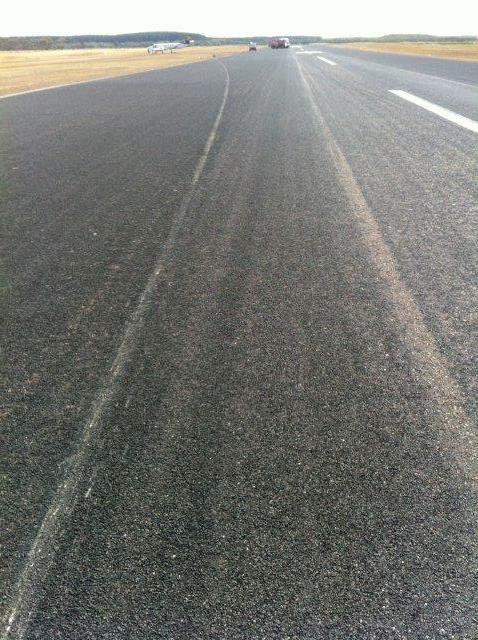
Figure 2: Damage to runway as a result of contact with the left main landing gear following failure
The runway excursion involving Fairchild Industries Metro 23 VH-UUB at Portland, Victoria, on 20 February 2014, was the result of the failure of a lug on yoke of the wheel assembly on the left main landing gear (MLG) during the landing roll. The failure of the lug disconnected the torque link between the upper MLG strut and the lower wheel assembly; this allowed the wheel assembly to rotate through 90° with respect to the direction of travel. This effectively resulted in a large braking force on the left side of the aircraft. The flight crew were unable to counteract that asymmetric braking force and as a result, the aircraft veered off the runway
Failure of the MLG yoke lug
The yoke lug fractured as a result of a fatigue cracking mechanism with crack initiation points located in the bore of the lug at areas of significant wear and corrosion pitting. The fatigue crack progressed through most of the lug cross section before final fracture during the occurrence landing.
Corrosion pits act as stress concentrators and significantly reduce both the fatigue crack initiation life of the component as well as the crack initiation threshold stresses. The corrosion, wear and cracking had likely been present in the lug bore for a significant period of time prior to failure occurring. Early indications of corrosion and cracking on the lug bore would not have been visible during the inspections prescribed in the inspection manual, without first disassembling the affected parts. Neither the detailed nor routine inspections explicitly required an inspection of the lug bore, although the manual contained a general definition of a detailed inspection that required components to be disassembled for examination. The list of required inspection items also implied that some disassembly would be required to adequately inspect various components. The operator indicated that while no disassembly was performed, a torque link freeplay inspection was performed which would have led to further examinations if anomalies, such as excessive movement, were found.
There were several factors that influenced corrosion of the yoke lug bore. Sealing of the disused pin holes in this occurrence was not adequate as the sealant had either broken down over time or otherwise disbonded and come loose during service, providing additional entrance routes for moisture or other corrosives. Another entrance route was associated with wear on the yoke lug flanks where significant pitting was identified. Wear on the flanks and in the bore of the lug was sufficient to remove the protective anodic coating, which increased the susceptibility of the parts to corrosion. With corrosion pitting being a precursor to the fatigue failure of the component, improvement of corrosion protection in the affected areas would further reduce the likelihood of this type of occurrence.
Safety issues and actions
The safety issues identified during this investigation are listed in the Findings and Safety issues and actions sections of this report. The Australian Transport Safety Bureau (ATSB) expects that all safety issues identified by the investigation should be addressed by the relevant organisation(s). In addressing those issues, the ATSB prefers to encourage relevant organisation(s) to proactively initiate safety action, rather than to issue formal safety recommendations or safety advisory notices.
Depending on the level of risk of the safety issue, the extent of corrective action taken by the relevant organisation, or the desirability of directing a broad safety message to the aviation industry, the ATSB may issue safety recommendations or safety advisory notices as part of the final report.
Where relevant, safety issues and actions will be updated on the ATSB website as information comes to hand. The initial public version of these safety issues and actions are in PDF on the ATSB website.
Safety issue title – Inadequate inspection procedures
The maintenance program for the aircraft’s landing gear did not adequately provide for the detection of corrosion and cracking in the yoke lug bore.
Purpose of safety investigations & publishing information
Purpose of safety investigations
The objective of a safety investigation is to enhance transport safety. This is done through:
identifying safety issues and facilitating safety action to address those issues
providing information about occurrences and their associated safety factors to facilitate learning within the transport industry.
It is not a function of the ATSB to apportion blame or provide a means for determining liability. At the same time, an investigation report must include factual material of sufficient weight to support the analysis and findings. At all times the ATSB endeavours to balance the use of material that could imply adverse comment with the need to properly explain what happened, and why, in a fair and unbiased manner. The ATSB does not investigate for the purpose of taking administrative, regulatory or criminal action.
Terminology
An explanation of terminology used in ATSB investigation reports is available here. This includes terms such as occurrence, contributing factor, other factor that increased risk, and safety issue.
Publishing information
Released in accordance with section 25 of the Transport Safety Investigation Act 2003
Ownership of intellectual property rights in this publication
Unless otherwise noted, copyright (and any other intellectual property rights, if any) in this report publication is owned by the Commonwealth of Australia.
Creative Commons licence
With the exception of the Coat of Arms, ATSB logo, and photos and graphics in which a third party holds copyright, this publication is licensed under a Creative Commons Attribution 3.0 Australia licence.
Creative Commons Attribution 3.0 Australia Licence is a standard form licence agreement that allows you to copy, distribute, transmit and adapt this publication provided that you attribute the work.
The ATSB’s preference is that you attribute this publication (and any material sourced from it) using the following wording: Source: Australian Transport Safety Bureau
Copyright in material obtained from other agencies, private individuals or organisations, belongs to those agencies, individuals or organisations. Where you wish to use their material, you will need to contact them directly.
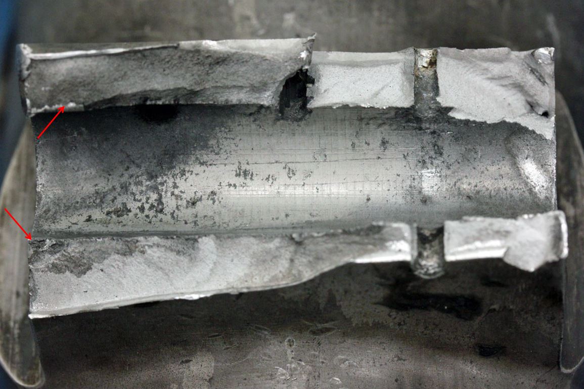
On 31 March 2013, a Cessna Aircraft Company 441 aircraft, registered VH-XBC, arrived at Coonawarra Airport, SA, following a charter flight from Adelaide, SA. The pilot reported that the initial flare and touchdown was normal, however during the landing roll, he heard a distinct ‘pop’ or ‘bang’ sound, after which the aircraft began veering to the left. Initially the pilot was able to maintain directional control and keep the aircraft on the runway, however as it slowed, it began pivoting around the left landing gear and came to rest to the left of the paved runway surface. There were no injuries to passengers or crew.
What the ATSB found
The runway excursion resulted directly from the failure of the left main landing gear trunnion, which allowed the left main wheel to displace upward and contact the wing underside – producing an asymmetric and uncontrolled braking effect. Both the ATSB and component manufacturers’ laboratory examinations attributed the trunnion failure to the development and growth of progressive fatigue cracking through the horizontal beam and central gusset section, with cracking propagating to the point where nominal landing loads produced the final overstress fracture and collapse of the assembly. Due to the extent of post-failure damage sustained by the fracture surfaces, neither laboratory examination was able to specifically identify the factors behind the initial development of the fatigue cracking.
The ATSB’s research of Australian and international air safety records did not identify any other instances of this specific mode of failure within the trunnion type, nor was the manufacturer aware of any known cracking or related problems with the trunnion in the affected areas. As such, it is likely that the event was an isolated occurrence, and consequently, the likelihood of similar occurrences in the future is low.
What's been done as a result
In response to this occurrence, the aircraft operator undertook a targeted, one-off non-destructive inspection of the trunnions from the four other aircraft in its fleet. All were found to be defect free. Additionally, the operator’s maintenance schedule has been extended to include the eddy-current inspection of the trunnion gusset/web regions concurrently with the routine 2000-cycle periodic inspections specified by the aircraft manufacturer.
Safety message
While the failure sustained in this instance was an unusual and isolated case, it does highlight the necessity of general vigilance and attention to detail during general visual inspections, or during other examinations of structures and components. Such activity can present opportunities for the detection of emerging or unknown airworthiness issues that may not have otherwise been identified during prescribed maintenance programs.