The ATSB is investigating a flight control issue involving a Beech Aircraft Corp 35-B33, registered VH-NEW, at Griffith Airport, New South Wales, on 11 May 2026.
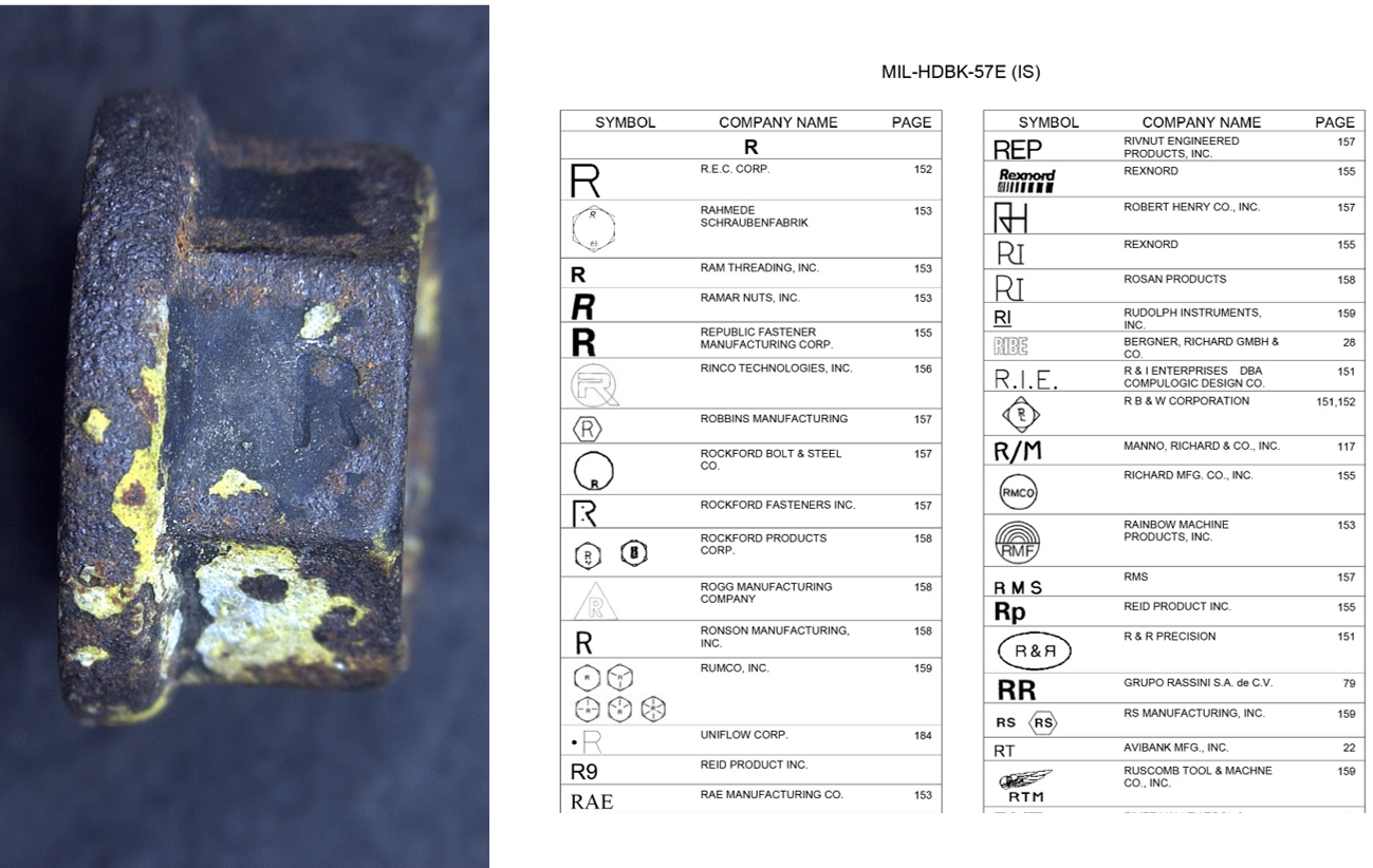
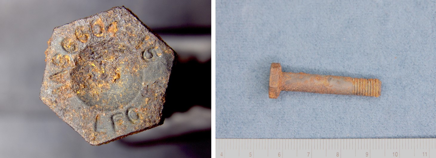
It was reported that, during the initial climb the instructor and student on board the aircraft detected a reduction of aileron and elevator effectiveness. The student held the control yoke stable while the instructor controlled the aircraft with elevator and rudder inputs and conducted a successful return to Griffith Airport. An engineering inspection later revealed a bolt had been liberated from the control torque link due to a missing split pin.
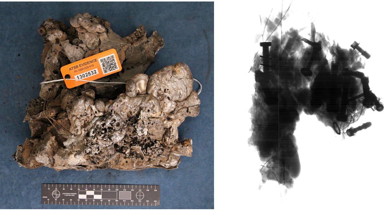
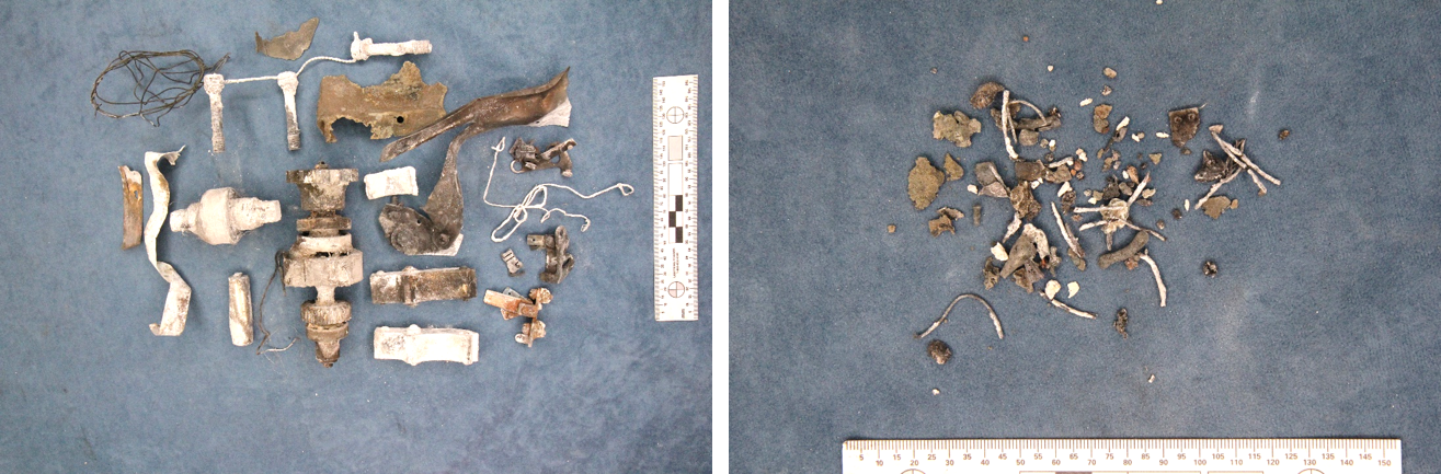
The evidence collection phase of the investigation will involve examining the recovered components, interviewing witnesses and involved parties, examination of maintenance records, retrieving and reviewing recorded data, and the collection of other relevant information.
A final report will be released at the conclusion of the investigation. Should a critical safety issue be identified during the course of the investigation, the ATSB will immediately notify relevant parties, so that appropriate safety action can be taken.
Occurrence summary
Investigation number
AO-2026-078
Occurrence date
11/05/2026
Occurrence time and timezone
14:30 Australian Eastern Standard Time
Location
Griffith Airport
State
New South Wales
Report status
Pending
Anticipated completion
Q4 2026
Investigation level
Short
Investigation type
Occurrence Investigation
Investigation phase
Evidence collection
Investigation status
Active
Aviation occurrence category
Control issues, Flight control systems
Occurrence class
Serious Incident
Highest injury level
None
Aircraft details
Manufacturer
Beech Aircraft Corp
Model
35-B33
Registration
VH-NEW
Serial number
CD-615
Sector
Piston
Operation type
Part 141 Recreational, private and commercial pilot flight training
Activity
General aviation / Recreational-Instructional flying-Instructional flying - dual
Occurrence Briefs are concise reports that detail the facts surrounding a transport safety occurrence, as received in the initial notification and any follow-up enquiries. They provide an opportunity to share safety messages in the absence of an investigation. Because occurrence briefs are not investigations under the Transport Safety Investigation Act 2003, the information in them is de-identified.
What happened
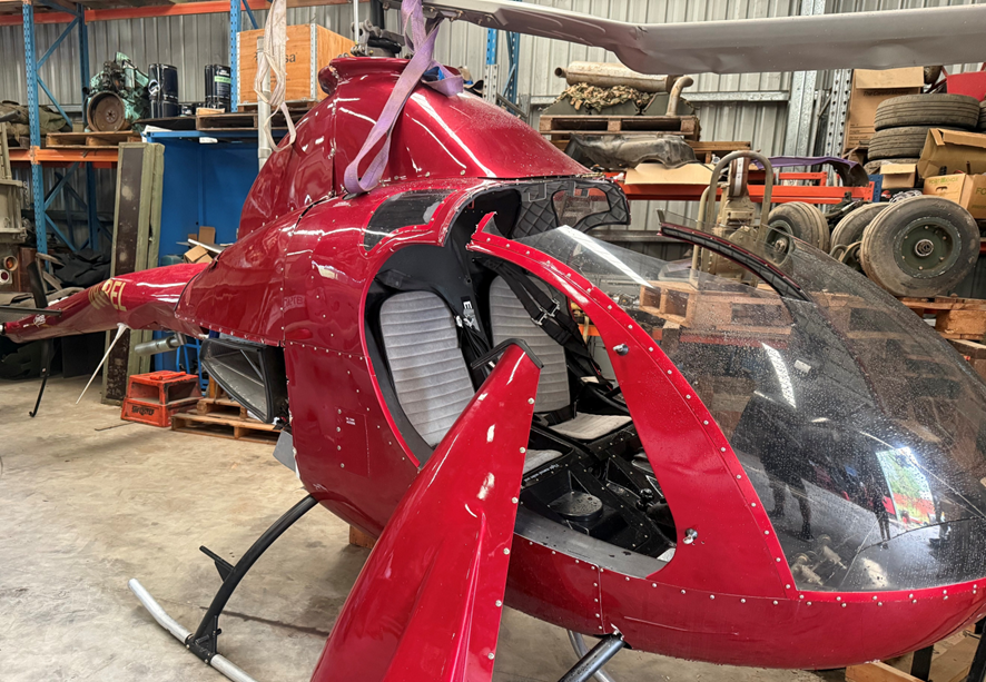
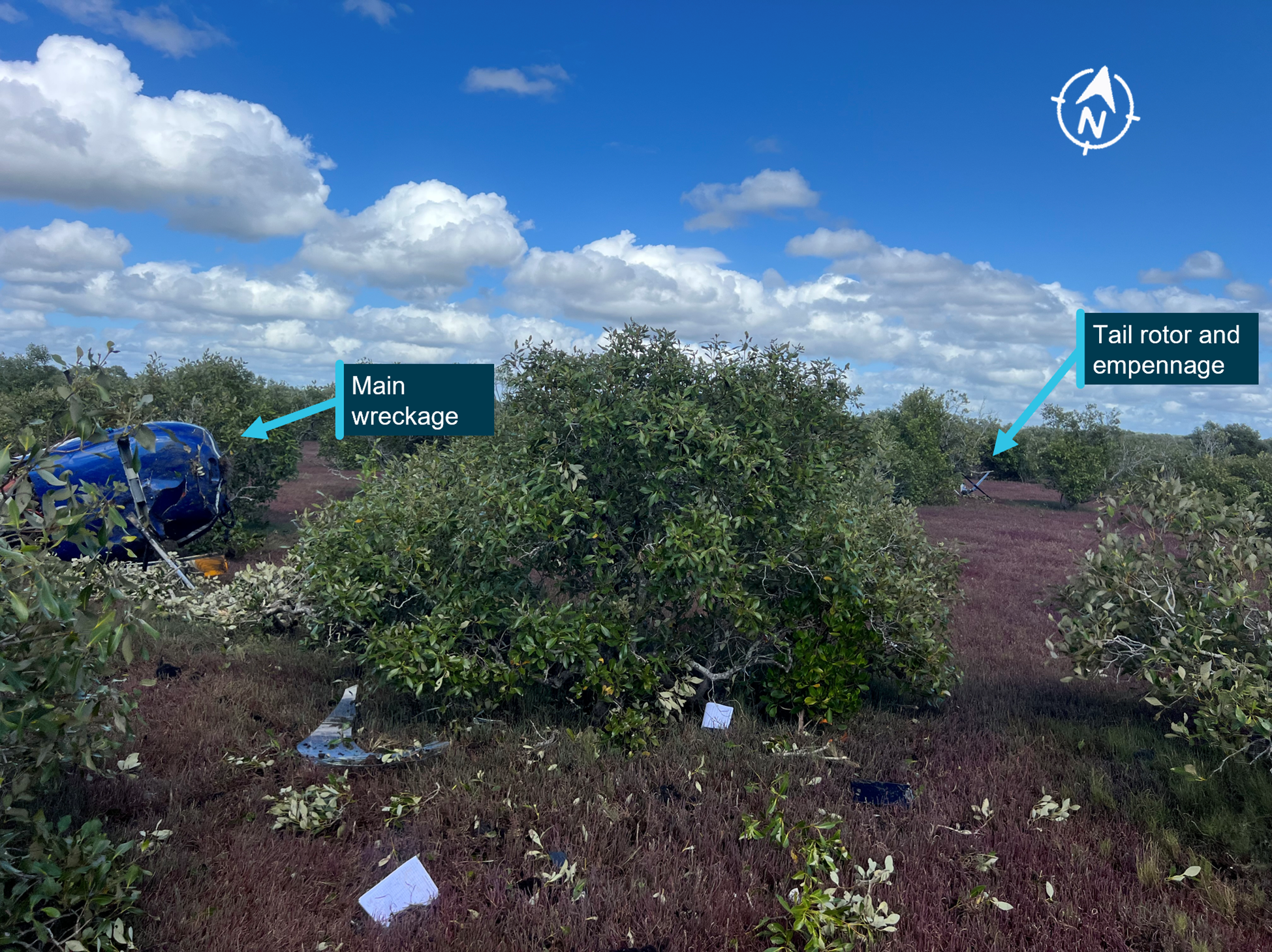
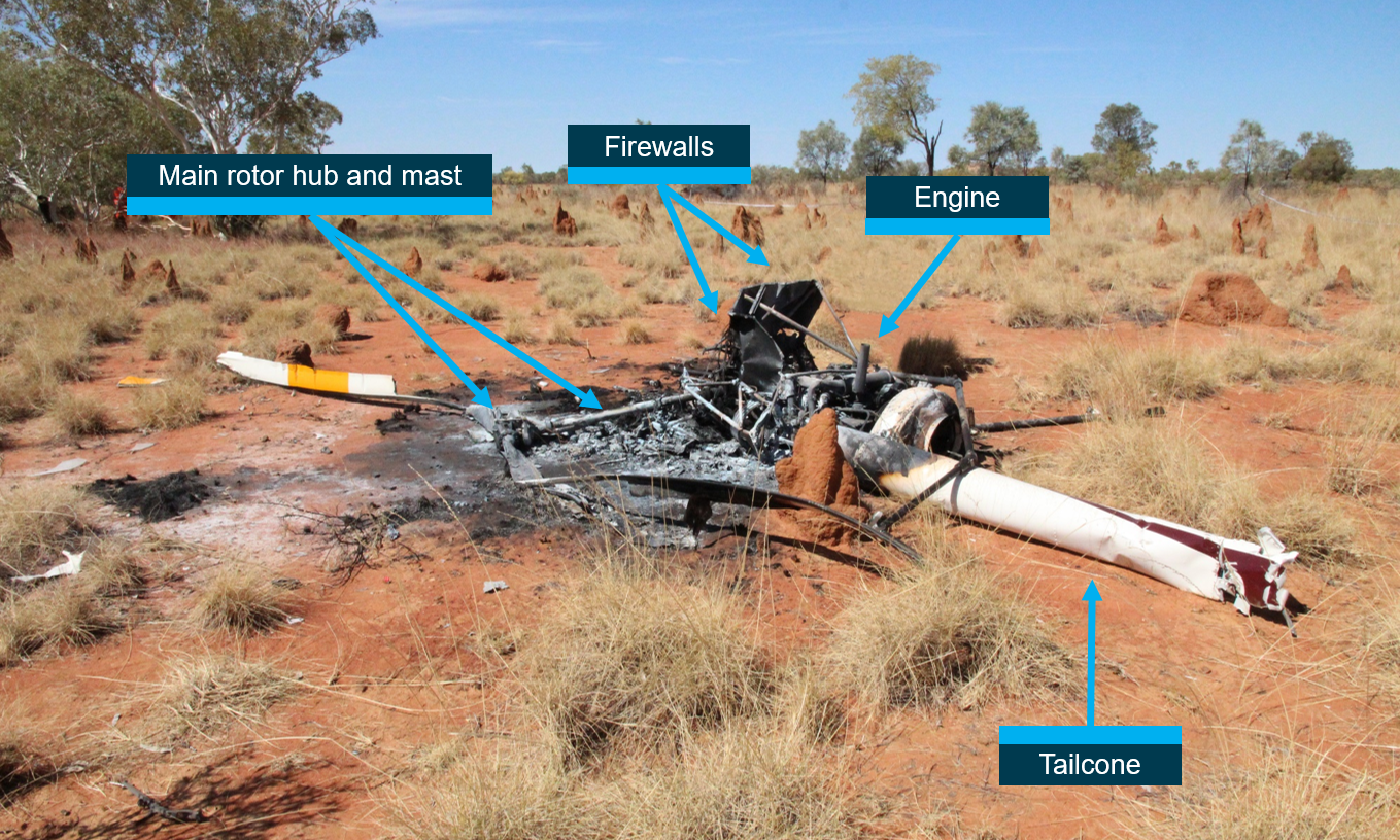
On the morning of 18 January 2026, the pilot of a RotorWay Exec 90 amateur-built light helicopter was conducting a local flight from a private property near Tamborine, Queensland, with one passenger on board. The pilot reported that during the hover, in preparation for landing, they experienced a sudden loss of tail rotor authority, followed by the onset of uncontrolled yaw[1] and rotation. To counter, the pilot lowered the collective[2] and set the helicopter down, however the helicopter’s rotation as it contacted the ground caused it to roll over and sustain substantial damage. Neither the pilot nor passenger were injured.
Figure 1: Damaged helicopter after recovery
Source: Operator supplied
Engineering information
The RotorWay Exec 90 is a kit-produced light utility helicopter manufactured by the RotorWay Helicopter Manufacturing Company (formerly RotorWay International) and intended for amateur construction. As-designed, the helicopter has a maximum take-off weight (MTOW) of 680 kg (1,500 lb) and is powered by a horizontally opposed 4-cylinder piston engine delivering 112 kW (150 hp).
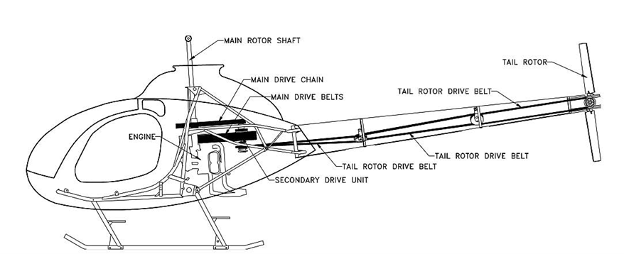
The Exec 90 powertrain employed a v-belt system that transferred drive to the tail rotor through a series of 3 belts and 2 idlers, extending from the secondary drive unit adjacent to the engine, through the tail boom, to the tail rotor pulley (Figure 2).
Source: UK Air Accidents Investigation Branch report AAIB-27186 (AAIB Bulletin 8/2022)
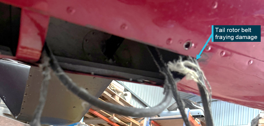
At the time of the accident, the helicopter had accumulated 64 hours total time in service. Upon inspection after the accident, evidence of the failure of the centre tail rotor belt was found within the tail boom structure – consistent with the loss of tail rotor effectiveness experienced by the pilot prior to the ground contact. The pilot reported that the tail rotor belt had operated for approximately 30–40 hours since new.
Figure 3: Remnants of a loose / fractured tail rotor drive belt found within the tail boom
Source: Operator supplied, annotated by ATSB
Inspections and service bulletins
The pilot reported that tail rotor belt tension had been checked with the manufacturer’s recommended tool before the flight, and noted that there were no indications of imminent belt failure leading up to the loss of tail rotor drive.
Section 3 (D) of the RotorWay Exec 90 flight manual requires a pre-flight inspection of the tail rotor drive components, including the condition and tension of the drive belts, and includes the caution:
IMPORTANT: New belts will tend to stretch and become loose. Belt tension must be monitored and adjusted frequently until stretching has stopped.
Further, the helicopter kit manufacturer has published several mandatory and advisory service bulletins applicable to the Exec 90 helicopter tail rotor drive system.
Bulletin number
Publication date
Subject
M-07 (mandatory)
8 September 1992
Prohibition of certain tail rotor belt makes
M-20 (mandatory)
4 April 2002
Inspection for proper tail rotor belt routing
A-20 (advisory)
28 November 1994
Inspection and importance of tail rotor belt tension
A-21 (advisory)
12 May 1995
Tail rotor belt inspection, tensioning, and temperature monitoring
A-25 (advisory)
21 December 1995
Cold weather inspection of tail rotor belt tension
A-36 (advisory)
4 April 2002
Inspection for proper tail rotor belt routing
Most of these bulletins centred on the importance of regular inspection and checking of tail rotor belt tension, and bulletin A-21 further noted:
Advisory Bulletin A-20 (dated November 28, 1994) stressed the importance of checking the condition and tension of the belts before every flight. Although this may be time consuming, these pre-flight checks are essential to the continued safe operation of your helicopter.
Safety message
RotorWay Exec 90 helicopters (and related types with belt-driven tail rotor systems) have an established sensitivity to tail rotor belt tension, with an operational history of failures associated with improperly tensioned belts.
Pilots, owners and operators of these helicopters are reminded to ensure that all applicable checks, inspections and maintenance activities are carried out on the tail rotor drive system, with particular attention to the tension, condition and service life of the belts.
About this report
Decisions regarding whether to conduct an investigation, and the scope of an investigation, are based on many factors, including the level of safety benefit likely to be obtained from an investigation. For this occurrence, no investigation has been conducted and the ATSB did not verify the accuracy of the information. A brief description has been written using information supplied in the notification and any follow-up information in order to produce a short summary report, and allow for greater industry awareness of potential safety issues and possible safety actions.
[1]Yaw: the motion of an aircraft about its vertical or normal axis.
[2]Collective: a primary helicopter flight control that simultaneously affects the pitch of all blades of a lifting rotor. Collective input is the main control for vertical velocity.
Occurrence Briefs are concise reports that detail the facts surrounding a transport safety occurrence, as received in the initial notification and any follow-up enquiries. They provide an opportunity to share safety messages in the absence of an investigation. Because occurrence briefs are not investigations under the Transport Safety Investigation Act 2003, the information in them is de-identified.
What happened
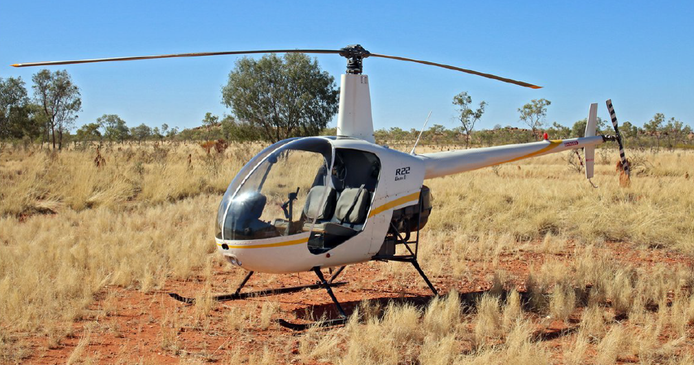
On 21 October 2025, a Robinson R22 helicopter with one pilot on board was conducting a private flight from Jimboomba to Southport, Queensland.
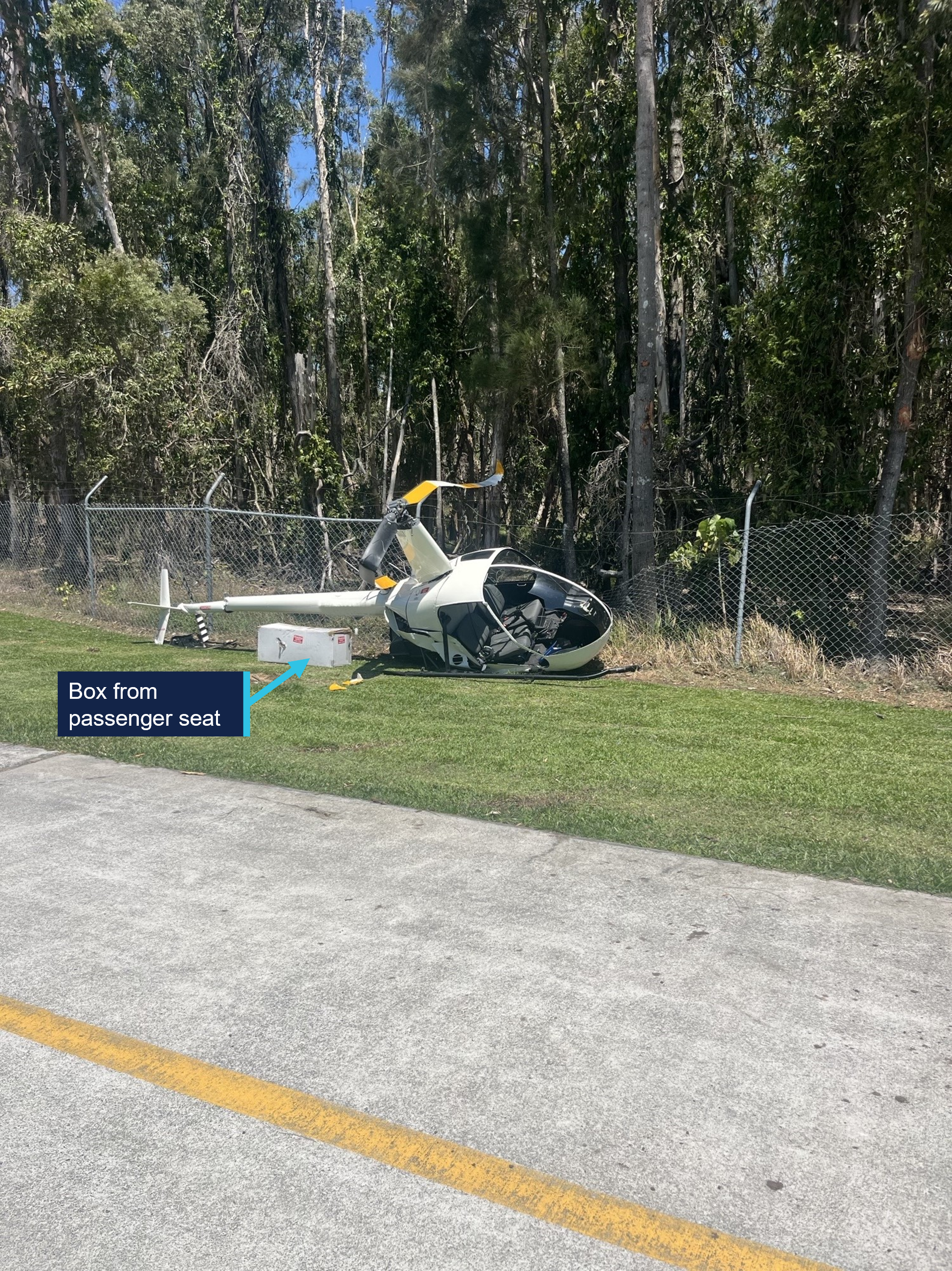
Prior to departure, the pilot loaded a box of freight, approximately 1,000 mm long, 350 mm wide and 400 mm deep, weighing 10 kg, onto the passenger seat and secured it by wrapping the seatbelt around the box. The flight departed Jimboomba at 1033 local time with a flight time of approximately 12 minutes.
As the pilot turned onto the base leg for final approach to runway 01 at Southport, the box on the passenger seat shifted and interfered with the cyclic[1] control resulting in the helicopter being unable to turn left. The helicopter then veered to the right and as the pilot focused their attention on moving the box, they lost control of the helicopter which came into contact with trees before colliding with terrain, resulting in substantial damage (Figure 1). The pilot sustained serious injuries in the accident.
Figure 1: Post-impact damage
Source: Queensland Police, annotated by the ATSB
Safety message
Pilots must adhere to CASA Regulation 91.610 (2) (b) Carriage of cargo – unoccupied seats, which states that the cargo, and the means of restraint of the cargo, must not interfere with the safe operation of the aircraft.
The ATSB has had 3 occurrences reported in a 15-year period involving Robinson R22 helicopters carrying cargo on the passenger seat which has interfered with the helicopter’s flight controls. All 3 of these occurrences resulted in a collision with terrain and substantial damage.
About this report
Decisions regarding whether to conduct an investigation, and the scope of an investigation, are based on many factors, including the level of safety benefit likely to be obtained from an investigation. For this occurrence, no investigation has been conducted and the ATSB did not verify the accuracy of the information. A brief description has been written using information supplied in the notification and any follow-up information in order to produce a short summary report, and allow for greater industry awareness of potential safety issues and possible safety actions.
[1]Cyclic: a primary helicopter flight control that is similar to an aircraft control column. Cyclic input tilts the main rotor disc, varying the attitude of the helicopter and hence the lateral direction.
Occurrence summary
Mode of transport
Aviation
Occurrence ID
AB-2025-057
Occurrence date
21/10/2025
Location
Southport Aerodrome
State
Queensland
Occurrence class
Accident
Aviation occurrence category
Collision with terrain, Flight control systems, Loading related, Loss of control, Unrestrained occupants/objects
On 15 April 2025, an Embraer ERJ 190-100, registered VH-UZD, was conducting a passenger transport flight from Sydney, New South Wales, to Launceston, Tasmania. After commencing approach to Launceston, the flight crew received multiple caution messages including a SLAT FAIL caution. The flight crew discontinued their approach and after completing the relevant checklists elected to divert to Melbourne, Victoria, as it was the longest available runway in the region. The remainder of the flight was uneventful, and the aircraft landed safely.
Post-flight troubleshooting determined that a torque tube in the left wing slat drive system had disconnected as it had been incorrectly assembled when it was last refitted.
What the ATSB found
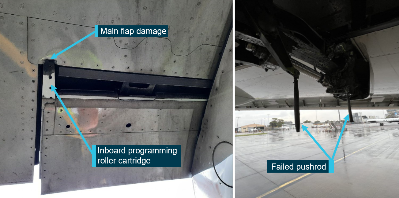
The ATSB identified a similar occurrence with another of the operator’s Embraer ERJ 190‑100 aircraft, VH-UYB, where a torque tube in the left wing flap drive system had disconnected as it had been incorrectly assembled when it was last refitted.
The occurrences were similar in that the locking bolts that secured the torque tubes to their actuators had not been fitted correctly into the holes of the splined shafts, since the torque tubes had been incorrectly positioned during installation.
In both occurrences, those carrying out and certifying for the torque tube installations did not identify that they had been incorrectly assembled.
These errors occurred at different maintenance providers, and reportedly from January 2005–August 2011 in the worldwide fleet of Embraer 170, 175, and 190 aircraft (all sharing similar componentry), there have been 5 similar occurrences related to incorrect torque tube installation.
What has been done as a result
The operator, Alliance Airlines, issued a maintenance notice that detailed the flap torque tube disconnect affecting VH-UYB and the slat torque tube disconnect affecting VH-UZD. This notice reiterated the aircraft maintenance manual information for the correct installation of flap and slat torque tubes.
The maintenance organisation added an additional task card that is automatically issued when work is scheduled on the E190 slat system torque tubes that provides guidance in addition to the aircraft maintenance manual to mitigate the incorrect assembly of torque tubes on their splines. A similar additional task card was being developed for the E190 flap system torque tubes.
Safety message
Historical occurrence and technical information provide an opportunity to review known errors prior to commencing particular maintenance activities, thereby reducing the possibility of further errors occurring. When an error does occur, this information also provides a means to bolster the actions taken to prevent re-occurrences.
This information can be available from multiple sources including the manufacturer, national aviation authorities (such as CASA or the FAA), accident investigation authorities, and the safety management systems of operators and maintenance organisations.
The investigation
The ATSB scopes its investigations based on many factors, including the level of safety benefit likely to be obtained from an investigation and the associated resources required. For this occurrence, the ATSB conducted a limited-scope investigation in order to produce a short investigation report, and allow for greater industry awareness of findings that affect safety and potential learning opportunities.
The occurrence
Previous maintenance
In November 2024, an Embraer ERJ 190-100 aircraft, registered VH-UZD and operated by Alliance Airlines, commenced a heavy maintenance[1] check by Rockhampton Aviation Maintenance in Rockhampton, Queensland. A team comprising 2 aircraft maintenance engineers (AMEs) was tasked with inspecting and lubricating the leading-edge slat drive system (see Embraer E190 slats and flaps). This involved removing, cleaning, lubricating, and refitting each slat torque tube in turn. A licensed aircraft maintenance engineer (LAME) briefed the AMEs on what was required.[2] The LAME was familiar with the task but was unaware of any historical issues with the task (see Maintenance requirements). The work was carried out in a new facility with good lighting. Access to the components was good, and a purpose-built platform allowed the work to be carried out with the relevant components at eye level.
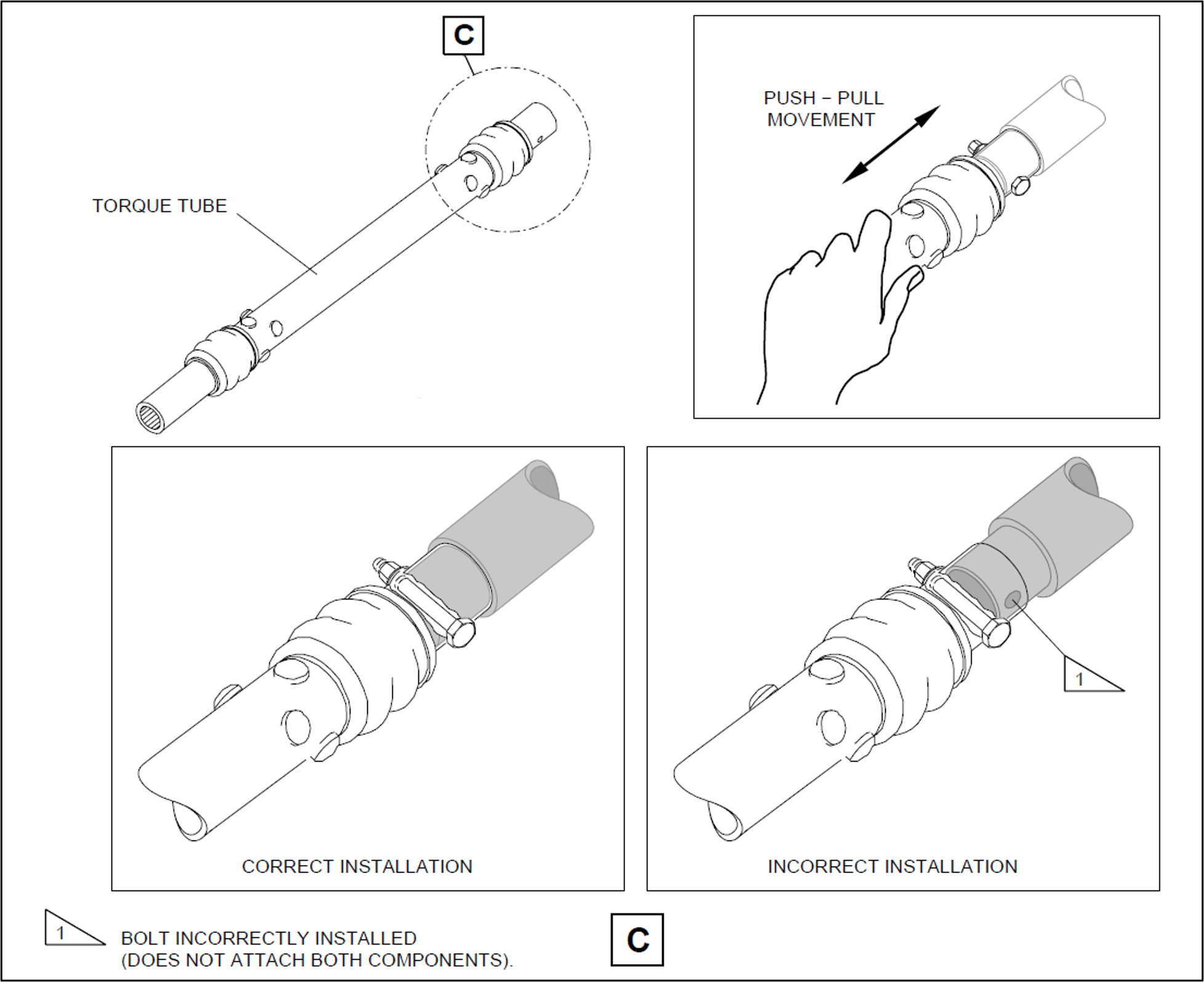
Prior to commencing work, brakes internal to the power drive units (PDUs) (which drive the flap and slat torque tubes) were electrically released as required by the aircraft maintenance manual (AMM) procedure. The AMEs printed a copy of the relevant AMM procedure, and worked together on the torque tube driving the left-wing outboard actuator for slat number 4. The PDU brakes were also required to be released prior to installing the torque tubes, however, it could not be established whether this took place (the PDU brakes reapply when power is removed). After refitting the outboard actuator torque tube, a push-pull check was carried out to ensure it was locked in place, as required by the AMM. Unknown to the AMEs, when this torque tube was refitted, it had not been positioned far enough onto the actuator’s splined shaft for the locking bolt to secure it (Figure 1, lower right). The locking bolt was inadvertently installed beyond the end of the spline (shown in grey) rather than through the hole as required.
One AME then continued work on the left wing and the other moved to the right wing slat drive system to work alone. The remaining slat torque tubes were correctly fitted.
After this work was completed, the LAME inspected the installation of the torque tubes and their locking bolts, and a second LAME carried out an independent inspection[3] of the work. The heavy maintenance check was completed in March 2025, and the aircraft was returned to service.
On 15 April 2025, 50 flights after returning to service from heavy maintenance, the aircraft was being operated on a passenger transport flight from Sydney, New South Wales, to Launceston, Tasmania, by Alliance Airlines for QantasLink. After commencing approach to Launceston, the flight crew received multiple caution messages[4] on the aircraft’s engine indicating and crew alerting system (EICAS) including a SLAT FAIL caution. The flight crew discontinued the approach and requested clearance from air traffic control for vectors[5] so they could action the relevant quick reference handbook (QRH) checklists for the caution messages.
The flight crew completed the QRH checklist. As the slat failure would require landing with the slats and flaps up, the flight crew elected to divert to Melbourne Airport, Victoria, as it had the longest available runway in the region. The flight crew declared a PAN PAN[6] and commenced the diversion to Melbourne. After climbing to 19,000 ft the aircraft was flown to Melbourne at 220 kt as required by the QRH because of the slat failure. The aircraft landed at Melbourne without further incident.
Post-flight inspection
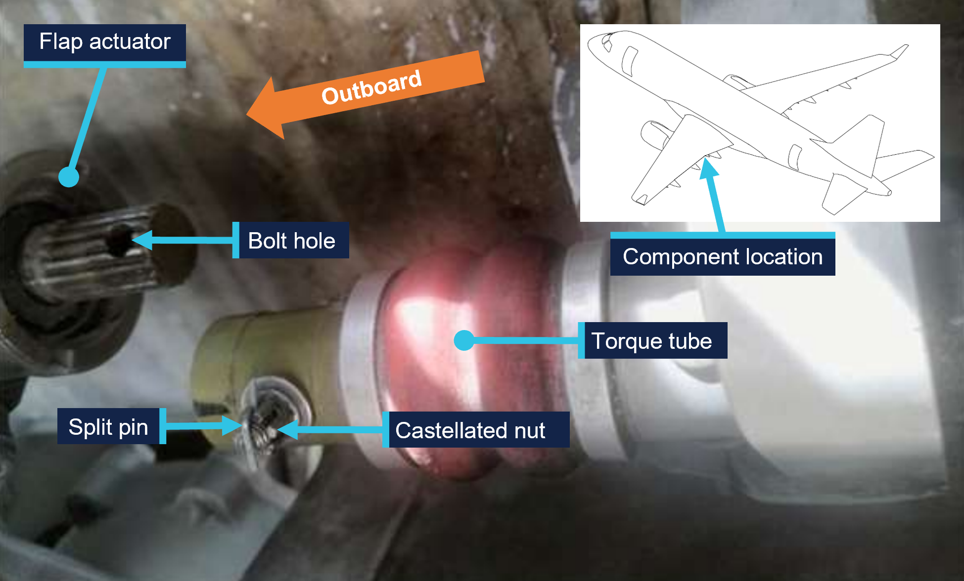
Post-flight inspection determined that the torque tube for the left wing slat number 4 outboard actuator had disconnected as the locking bolt fitted to the torque tube had not passed through the corresponding hole in the actuator’s splined shaft when it was last refitted (Figure 2).
Figure 2: VH-UZD left wing outboard actuator for slat number 4 and torque tube, shown disconnected after the occurrence flight
Source: Alliance Airlines, annotated by the ATSB
Context
Aircraft information
The Embraer ERJ 190-100 IGW (E190) is a narrow-body aircraft used for air transport operations and powered by 2 General Electric CF34-10E5 turbofan engines. VH-UZD was manufactured in Brazil in 2008 and registered in Australia on 31 January 2022.
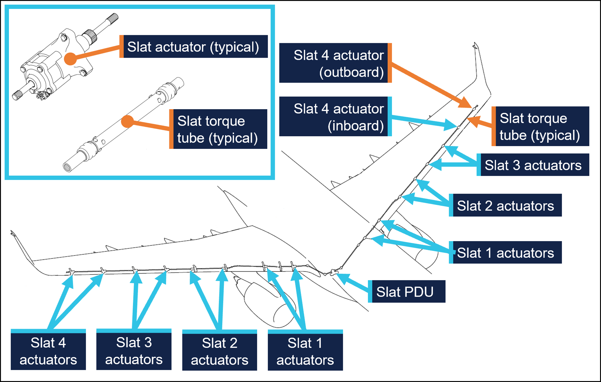
Embraer E190 slats and flaps
The E190 is fitted with devices to increase the lift produced by its wings during take-off and landing. On the leading edges of the wings there are 8 slat panels and on the trailing edges of the wings there are 4 flap panels (Figure 3), where each set (slats/flaps) extends and retracts together.
Figure 3: Embraer E190 slats and flaps
Source: Embraer, annotated by the ATSB
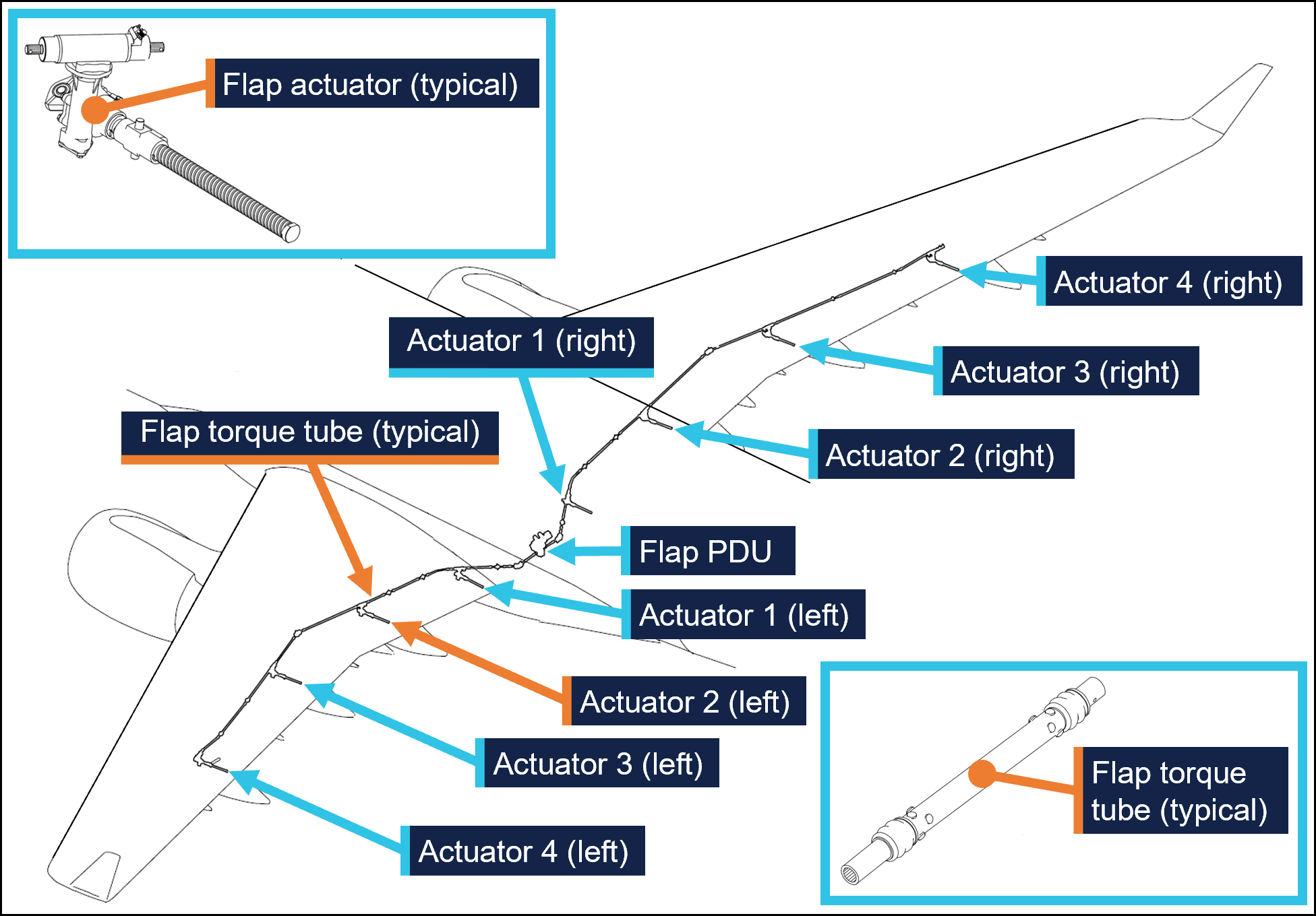
Slat and flap extension and retraction is controlled from the cockpit by using the slat/flap control lever (SFCL). When the SFCL is moved from its 0 (up) position,[7] the flap and slat power drive units (PDUs) drive torque tubes which in turn drive actuators, transferring the rotary motion of the torque tubes to linear motion that extends the slats and flaps (Figure 4 and Figure 5).
Each PDU has 2 internal brakes that are engaged under spring force and released electrically, such that the brakes would re-engage when power is removed. There are 26 torque tubes in the slat drive system and 22 torque tubes in the flap drive system.
In the event of a slat or flap failure, redundant detection and protection systems prevent them operating in such a way that may compromise safety of flight.
Figure 4: Embraer E190 slat drive system
Source: Embraer, annotated by the ATSB
Figure 5: Embraer E190 flap drive system
Source: Embraer, annotated by the ATSB
Maintenance requirements
The slat and flap torque tubes are removed periodically for the actuator splines to be lubricated with grease. They may also need to be removed to replace associated components. A detailed visual inspection of the slat and flap drive system is also carried out periodically and includes a requirement to check that the torque tubes are correctly secured in place by their locking bolts. No detailed visual inspections of the slat system had been required between the heavy maintenance in November 2024 and the occurrence flight.
The procedure to remove and install the slat and flap torque tubes is detailed in the aircraft maintenance manual (AMM). As part of this procedure, the slat or flap PDU brakes are disengaged electrically to eliminate any residual torque in the system that may impede (through friction) the removal of the torque tubes. For the same reason, the brakes must also be disengaged for their installation.[8] Embraer advised the ATSB of the importance of removing residual torque for the installation.
Rockhampton Aviation Maintenance noted during its investigation into the occurrence that excessive amounts of grease on the actuator splines can produce hydraulic resistance to re-assembly of the torque tube and therefore no more than what is required to lubricate the splines should be applied. It could not be determined whether this occurred during the maintenance of VH-UZD. The installation procedures for torque tubes in the AMM requires the old grease to be removed, new grease to be applied, and any unwanted grease to be removed prior to assembly.
The torque tubes interface with other components via splined shafts and are secured by locking bolts in conjunction with castellated nuts and split pins to prevent their inadvertent disconnection. There are 24 locking bolts in the slat drive system and 18 locking bolts in the flap drive system, all with this configuration.
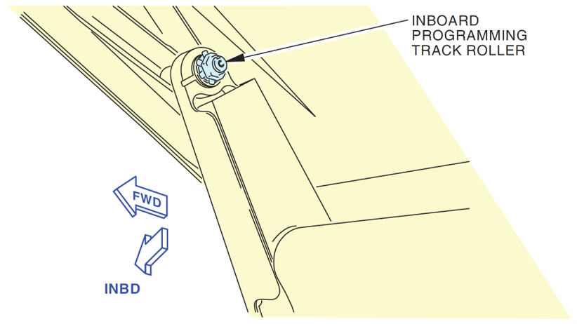
The AMM describes and illustrates a ‘push-pull’ check to determine the locking bolt has been correctly installed and had showed representative examples of correct and incorrect installation (Figure 1).
The torque tube locking bolts pass through holes close to the end of each actuator’s splined shaft. A correctly installed torque tube is visually apparent by less exposed splines (Figure 6). If a slat torque tube is incorrectly positioned[9] on a slat actuator the locking bolt will not capture the splined shaft and can lead to the torque tube disconnecting and slat failures.
Figure 6: Exemplar slat torque tube correctly fitted (upper image) and incorrectly fitted (lower image) to a slat actuator
A slat actuator and torque tube were correctly and incorrectly assembled on a workbench to create these images. Source: The maintenance organisation, annotated by the ATSB
Actions taken to prevent installation errors
In 2010 the AMM was amended to include the previously mentioned illustration (Figure1) showing the correct and incorrect installation of slat and flap torque tubes along with the push-pull test. This revision also added the requirement to release the PDU brakes.
Embraer communicated these changes by publishing a service newsletter SNL 190‑27‑0050 noting reports of incorrect slat or flap torque tube installation, advising that the AMM had been revised to mitigate future occurrences, and provided an overview of the revisions. This information was also published in Embraer’s safety magazine[10] (available to operators of E190s) and was contained in a document[11] published by the National Civil Aviation Agency of Brazil.
In October 2017 Embraer published an update on the issue in a document[12] that reiterated the previous actions taken to mitigate these occurrences. This document noted that from January 2005–August 2011 in the worldwide fleet of Embraer ERJ170, 175, 190, and 195 aircraft[13] there were 483 reports of slat or flap system failures. Of these, 5 were occurrences related to incorrect torque tube installation. Additionally, the document stated that the subject of incorrect torque tube installation was presented to civil aviation authorities in Europe and the Americas. It was concluded that no additional actions were required, as there were a small number of exposed aircraft, and there had been no reported events since the AMM was revised in 2010, and the manufacturer considered the issue closed.
Related occurrences
Incorrect flap torque tube installation
In late 2024, an Embraer ERJ 190-100 aircraft, registered VH-UYB and operated by Alliance Airlines for QantasLink, commenced a heavy maintenance check at a facility in Singapore. The torque tube driving the left wing flap actuator number 2 (see Embraer E190 slats and flaps) was removed to carry out flap actuator torque limiter checks. When fitted, the torque tube had not been positioned far enough onto the actuator’s splined shaft for the locking bolt to secure it.
On 10 November 2024, 35 flights after returning to service from heavy maintenance, the aircraft departed for a passenger transport flight. After take-off, the flight crew received a FLAP FAIL caution on the EICAS as the flaps were retracting. The flight crew initiated a turnback and the aircraft landed safely.
Engineering personnel later found that the locking bolt for the left wing flap actuator number 2 torque tube had not passed through the corresponding hole in the actuator splined shaft when it was last refitted (Figure 7).
Figure 7: VH-UYB left wing flap actuator 2 and torque tube
Source: Alliance Airlines, annotated by the ATSB
Other flight control event involving VH-UZD
On 18 April 2025, VH-UZD was operating from Adelaide, South Australia, to Canberra, Australian Capital Territory. When flaps were selected down, the slats began to extend but the flaps did not deploy, and the crew received multiple failure warnings. The flight crew diverted to Melbourne. Post-flight troubleshooting determined that the flap power drive unit (PDU) torque limiter had tripped, which is a problem unrelated to the investigation occurrence or the recent heavy maintenance check.
Safety analysis
Incorrect fitment of actuator torque tubes
When the torque tube for the left wing slat number 4 outboard actuator was refitted to VH-UZD in November 2024, it had not been positioned far enough onto the actuator’s splined shaft for the locking bolt to secure it in place. After re-entering service and conducting 50 flights, the torque tube disengaged from the actuator, and the slat system failed. Protection systems ensured the safety of flight was minimally affected.
Similarly, when another E190, VH-UYB, was under heavy maintenance at a different facility at around the same time, the torque tube driving the left wing flap actuator number 2 was incorrectly assembled in that the locking bolt had not passed through the hole in the actuator’s splined shaft. The torque tube disengaged 35 flights after the aircraft re-entered service and the flap system failed.
Non-detection of the error
The 2 AMEs who fitted the torque tube in VH-UZD did not identify that the torque tube had been incorrectly fitted. Further, the LAME checking this work and the second LAME carrying out the independent inspection of this work did not identify that it had been incorrectly assembled. The similar error affecting VH‑UYB also apparently remained undetected by those carrying out and certifying for the work.
As far as could be established, there were no physical or environmental factors that may have influenced the incorrect assembly of the torque tube. The work on VH-UZD was carried out in a new facility with good lighting, and access to the work area was good and could be carried out with the relevant components at eye level.
Ultimately, it is likely that not knowing the subtle difference in appearance of an incorrectly assembled slat torque tube (that is, as little as about 6.35 mm more of the actuator spline visible) contributed to the error not being detected by the 2 AMEs and the 2 LAMEs involved. Further, the remaining torque tubes in the slat drive system were correctly assembled, however their subtly different appearance did not trigger recognition that the original torque tube had been incorrectly assembled.
Available relevant information
Installation of the slat and flap drive system torque tubes is a simple task, but errors have occurred. Embraer noted that from January 2005–August 2011 in the worldwide fleet of Embraer 170, 175, 190 aircraft (all sharing similar componentry) there were 5 occurrences related to incorrect torque tube installation. The Embraer 190 has 24 locking bolts in the slat drive system and 18 in the flap drive system representing a total of 42 opportunities to incorrectly secure the torque tubes.
In 2010, Embraer made amendments to the aircraft maintenance manual to reduce the possibility of assembly errors. These were intended to remove any residual torque loads during removal and installation (by releasing the PDU brake), highlight the possibility of error with an illustration, and through the addition of the push-pull check, provide a means to detect an installation error.
These changes were communicated in multiple documents, such as a service newsletter, that were available to operators and maintainers of E190s. Review of such documents can assist in highlighting known issues and thereby prevent reoccurrence.
Findings
ATSB investigation report findings focus on safety factors (that is, events and conditions that increase risk). Safety factors include ‘contributing factors’ and ‘other factors that increased risk’ (that is, factors that did not meet the definition of a contributing factor for this occurrence but were still considered important to include in the report for the purpose of increasing awareness and enhancing safety). In addition ‘other findings’ may be included to provide important information about topics other than safety factors.
These findings should not be read as apportioning blame or liability to any particular organisation or individual.
From the evidence available, the following findings are made with respect to the flight control event involving Embraer E190, VH-UZD, 29 km south-east of Launceston Airport, Tasmania, on 15 April 2025.
Contributing factors
During scheduled maintenance, the locking bolt for the left outboard slat torque tube was not passed through the hole in the actuator’s splined shaft as the torque tube had been incorrectly positioned. The aircraft was released from maintenance, and 50 flights later, the torque tube disconnected, causing the slat system to fail.
Both licensed aircraft maintenance engineers inspecting the left outboard slat torque tube did not identify that it had been incorrectly assembled.
Safety actions
Whether or not the ATSB identifies safety issues in the course of an investigation, relevant organisations may proactively initiate safety action in order to reduce their safety risk. The ATSB has been advised of the following proactive safety action in response to this occurrence.
Safety action taken by Alliance Airlines
On 17 April 2025, Alliance Airlines issued a maintenance notice that detailed the flap torque tube disconnect affecting VH-UYB on 11 November 2024 and the slat torque tube disconnect affecting VH-UZD on 15 April 2025. This notice reiterated the aircraft maintenance manual information for the correct installation of flap and slat torque tubes.
Safety action taken by Rockhampton Aviation Maintenance
The maintenance organisation added an additional task card that is automatically issued when work is scheduled on the E190 slat system torque tubes. This task card provides guidance in addition to the aircraft maintenance manual to highlight the possibility of hydraulic lock caused by lubricant and the importance of releasing the PDU brake. Additionally, this task details a dimensional check to confirm the correct installation of torque tubes on their splined shafts. A similar additional task card was being developed for the E190 flap system torque tubes.
Sources and submissions
Sources of information
The sources of information during the investigation included:
Alliance Airlines
Centro de Investigação e Prevenção de Acidentes Aeronáuticos (Brazil)
Civil Aviation Safety Authority
Embraer
Rockhampton Aviation Maintenance
licenced aircraft maintenance engineer that made the final certification of the work
both aircraft maintenance engineers.
Submissions
Under section 26 of the Transport Safety Investigation Act 2003, the ATSB may provide a draft report, on a confidential basis, to any person whom the ATSB considers appropriate. That section allows a person receiving a draft report to make submissions to the ATSB about the draft report.
A draft of this report was provided to the following directly involved parties:
Alliance Airlines
Centro de Investigação e Prevenção de Acidentes Aeronáuticos (Brazil)
Civil Aviation Safety Authority
Embraer
Rockhampton Aviation Maintenance
licenced aircraft maintenance engineer that made the final certification of the work
both aircraft maintenance engineers.
Submissions were received from:
Embraer
Rockhampton Aviation Maintenance.
The submissions were reviewed and, where considered appropriate, the text of the report was amended accordingly.
Purpose of safety investigations
The objective of a safety investigation is to enhance transport safety. This is done through:
identifying safety issues and facilitating safety action to address those issues
providing information about occurrences and their associated safety factors to facilitate learning within the transport industry.
It is not a function of the ATSB to apportion blame or provide a means for determining liability. At the same time, an investigation report must include factual material of sufficient weight to support the analysis and findings. At all times the ATSB endeavours to balance the use of material that could imply adverse comment with the need to properly explain what happened, and why, in a fair and unbiased manner. The ATSB does not investigate for the purpose of taking administrative, regulatory or criminal action.
About ATSB reports
ATSB investigation reports are organised with regard to international standards or instruments, as applicable, and with ATSB procedures and guidelines.
Reports must include factual material of sufficient weight to support the analysis and findings. At all times the ATSB endeavours to balance the use of material that could imply adverse comment with the need to properly explain what happened, and why, in a fair and unbiased manner.
An explanation of terminology used in ATSB investigation reports is available here. This includes terms such as occurrence, contributing factor, other factor that increased risk, and safety issue.
Publishing information
Released in accordance with section 25 of the Transport Safety Investigation Act 2003
Ownership of intellectual property rights in this publication
Unless otherwise noted, copyright (and any other intellectual property rights, if any) in this report publication is owned by the Commonwealth of Australia.
Creative Commons licence
With the exception of the Commonwealth Coat of Arms, ATSB logo, and photos and graphics in which a third party holds copyright, this report is licensed under a Creative Commons Attribution 4.0 International licence.
The CC BY 4.0 licence enables you to distribute, remix, adapt, and build upon our material in any medium or format, so long as attribution is given to the Australian Transport Safety Bureau.
Copyright in material obtained from other agencies, private individuals or organisations, belongs to those agencies, individuals or organisations. Where you wish to use their material, you will need to contact them directly.
[1]Heavy maintenance is typically when an aircraft is removed from service for a period of time for more extensive inspections, checks, servicing, and modifications to be carried out.
[2]One of the AMEs had carried out this task previously. The other had experience maintaining E190s including slat and flap drive systems however had they had not previously removed and installed slat and flap torque tubes.
[3]Civil Aviation Regulation (CAR) 42G required independent inspections to be carried out on flight control systems when they were disturbed during maintenance.
[4]The caution messages presented were SLAT FAIL, SHAKER ANTICIPATED, and AOA [angle of attack] LIMIT FAIL.
[5]In this context, a vector is a heading given by air traffic control to a flight crew for navigation guidance.
[6]PAN PAN: an internationally recognised radio call announcing an urgency condition which concerns the safety of an aircraft or its occupants but where the flight crew does not require immediate assistance.
[7]The SFCL has 7 positions ranging from up (retracted) to fully extended slats and flaps.
[8]Embraer advised the ATSB that in a scenario where the PDU brakes had been released, and power was subsequently removed from the aircraft (thus reapplying the PDU brakes) this would not be expected to generate any residual torque in the slat or flap drive system. However, Embraer reiterated the importance of the PDU brakes being released when carrying out these tasks.
[9]These dimensions are for the slat actuator and torque tube interface. Dimensions vary for other components in the slat and flap systems.
On 26 February 2025, a Robinson Helicopter Company R22, with an instructor and a student on board, departed Archerfield Airport, Queensland, to conduct advanced emergency training at Pannikin Island in Moreton Bay, Queensland.
After practising emergency procedures and low-level flying, the student pilot performed several low-level torque turns, a manoeuvre not originally included in the lesson plan. During the final turn, the helicopter entered a low nose attitude and descended rapidly. The instructor attempted to recover, but due to the low height, was unsuccessful. The helicopter impacted the ground and skidded for some distance before rolling and coming to rest on its left side. The instructor sustained serious injuries and the student sustained minor injuries. The helicopter was destroyed.
What the ATSB found
Low‑level torque turns that were not part of the lesson plan, nor a requirement for commercial licence training, were conducted by a student pilot without a formal pre-flight briefing or guidelines. As the manoeuvre fell outside of the syllabus the ad hoc nature of its inclusion and conduct at the end of the lesson relied on an inflight briefing by the instructor to prepare the student for the exercise. Beginning the low-level torque turn exercise at 50 ft AGL rather than starting higher and working down as the student’s capability improved increased operational risk. Due to the low-level conduct of the exercise, this reduced the available safety margin and placed reliance on the instructor as the only risk control to recover from any unexpected mishandling of the sequence.
Although the instructor immediately identified that the helicopter was descending rapidly, and took the controls, their actions were unable to recover the helicopter before colliding with terrain. Environmental conditions may have further reduced the safety margin and complicated the low-level recovery.
The operator had no formal process for monitoring the return of training flights. This would likely delay any search and rescue response and reduce post-impact survivability of the helicopter occupants in the event of life-threatening injuries.
What has been done as a result
The operator reported that SARTIME procedures for the flying school have been revised.
Safety message
Ensuring and maintaining sufficient height for recovery is vital in a training environment when a student has limited experience to manage unexpected aircraft or helicopter behaviour.
All aspects of the lesson should be clearly briefed before flight including planned sequence, risks and hazards to ensure an understanding between instructor and student.
Instructors must rely on conservative in-flight decision‑making to manage risk during flight training operations and to anticipate and be ready to intervene quickly, especially during low-level, or elevated risk manoeuvres.
The investigation
The ATSB scopes its investigations based on many factors, including the level of safety benefit likely to be obtained from an investigation and the associated resources required. For this occurrence, the ATSB conducted a limited-scope investigation in order to produce a short investigation report, and allow for greater industry awareness of findings that affect safety and potential learning opportunities.
The occurrence
On 26 February 2025, an instructor and a pilot under instruction (student) were conducting an advanced emergency training exercise in a Robinson Helicopter Company R22 (R22), registered VH-8BW, operated by Utility Helicopters, leased from Heliflite. The training commenced from the operator’s company base at Archerfield Airport, Queensland.
At about 0700, the student conducted a daily inspection of the helicopter under the supervision of the instructor. The intended training flight formed part of the requirements for a commercial helicopter pilot licence and the lesson plan intended to cover advanced emergency procedures.
At about 0730 the helicopter, with the student flying, departed Archerfield Airport to the south‑east for a designated training area located in Moreton Bay. After reaching the uninhabited Pannikin Island training area, the emergency training commenced with autorotation[1] and tail rotor failure practise. After about 45 minutes, the student then commenced low-level flying practise, completing several clockwise laps around the island. These were completed between 50–100 ft above ground level (AGL) and at a speed of between 60–70 kt.
Toward the end of the lesson, the instructor recalled that the student requested to practise some agricultural flying operations, which included torque turns.[2] These manoeuvres were not on the lesson plan for the flight, or part of the commercial flight training syllabus, and there had been no plan to conduct them until this point. The instructor demonstrated the manoeuvre before the student took control and successfully completed 4 torque turns. The instructor reported these were conducted at a height of about 50 ft AGL.
The instructor stated that the low-level turns were conducted across the island roughly in an east–west direction. The exercise was conducted across the prevailing wind direction to avoid a downwind component on each low-level manoeuvre. Torque turns were performed on the eastern side of the island and procedural turns on the western side, with about 4 turns completed at each location. These were executed at a height of about 50 ft AGL.
As the lesson neared completion, they elected to do one more torque turn before returning to base. The instructor recalled noticing the wind had increased a little and had started gusting but stated that these were not considered abnormal conditions and that both he and the student had flown in these conditions before.
The instructor described that at the top of the last torque turn, they were at a height of 100–150 ft AGL when they began to descend to build airspeed and return to level flight. During the recovery, the instructor noticed that the nose of the helicopter was pointing slightly down toward the ground at a height of about 20 ft. The instructor recalled that they were about to correct the student when a sudden gust of wind increased the rate of descent. Aware of the ground proximity,the instructor immediately took over the controls and recalled moving the cyclic[3] aft to arrest the rate of descent. The instructor reported the helicopter shuddering, shaking, and experiencing a jolt in the collective but was unable to prevent the helicopter impacting the ground.
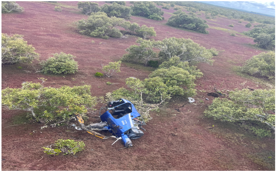
Both occupants recalled that everything happened quickly prior to ground contact and that the estimated speed at impact was about 60–70 kt. The instructor recalled that the helicopter impacted hard in a flared nose high attitude and that the stinger[4] contacted the ground first. The helicopter slid along the ground on its skids for about 40–50 m between mangrove bushes before the left skid dug into the muddy ground and dynamically rolled over.[5] The helicopter came to a stop on its left side after numerous rotations and was destroyed (Figure 1). The instructor recalled that the student remained in the helicopter momentarily after impact and then managed to exit and appeared to have had less injuries than themselves so was able to follow instructions to shut down the machine.
Figure 1: Accident site
Source: Student
The student turned off the battery master and assisted the instructor to exit the helicopter. The instructor was unsure if any staff would be in the office and recalled asking the student to use their mobile phone to call for help. They stated that calling the office would not be as effective as calling their partner, as they were aware that several of the staff were away on business. The company was contacted and another helicopter from the base at Archerfield Airport was then dispatched to collect both occupants. About 25 minutes later they were rescued by a colleague who arrived in another helicopter.
Emergency services were contacted, and an ambulance met the retrieval helicopter on arrival back at Archerfield Airport. Post-accident medical assessment determined that the instructor had sustained serious injuries and the student only minor injuries, both were taken to hospital for treatment.
Context
Aircraft information
The Robinson R22 is a 2-seat, 2-bladed, single-engine, light utility helicopter manufactured by Robinson Helicopter Company in the United States. It has a maximum all up weight of 622 kg. The R22 is powered by a Lycoming O-360 4-cylinder piston engine that is derated to 131 horsepower for take-off and 124 horsepower for cruise at 2,652 RPM. The R22 is mostly used for private operations, rotary wing flight training and agricultural operations.
The instructor reported that there were no mechanical issues identified with the helicopter during the daily inspection and pre-flight that would have precluded normal operation.
Flight controls
The helicopter was fitted with conventional light helicopter flight controls, such as dual cyclic controls for each seat, and a centre‑mounted collective.[6] The engine throttle is connected to collective inputs through a mechanical linkage; when the collective is raised, the throttle is opened and when lowered, the throttle is closed.
Pilot information
Instructor
The instructor held a commercial pilot licence (CPL-H) helicopter and had been an instructor with the operator for 3 years and 3 months. They began as a grade 3 instructor and progressed to a grade 1 instructor during their employment, logging about 2,800 flying hours. The instructor’s last proficiency check was 29 November 2024. The instructor obtained a low-level rating in 2021 and their low-level flight review for the R22 was valid until 13 November 2025. The instructor held a current Class 1 medical certificate.
Student pilot
The student pilot had been conducting training with the operator for about 3.5 years. Initially training for a private pilot licence (PPL-H) helicopter, they had not finalised the required ground theory or conducted a flight test. Although they did not hold a PPL-H, they continued training to obtain the required flight hours for a CPL-H.
Nearing completion of the commercial flight training, the student scheduled their lessons to coincide with their work commitments and they were not regular, but rather when time permitted. Their last lesson before the accident was conducted on 29 January 2025, about 4 weeks prior. They had previously completed advanced emergency training and the intention was to use the lesson as a refresher for CPL-H competency elements. The student reported they wanted to consolidate their low-level flying skills with a goal of working in the agricultural sector.
At the time of the accident the student had accrued 89 hours of pilot training with the operator. The student reported that about two thirds of all the lessons had been taken with the instructor involved in the accident and the remainder with head of operations (HOO) and one other instructor.
Meteorological information
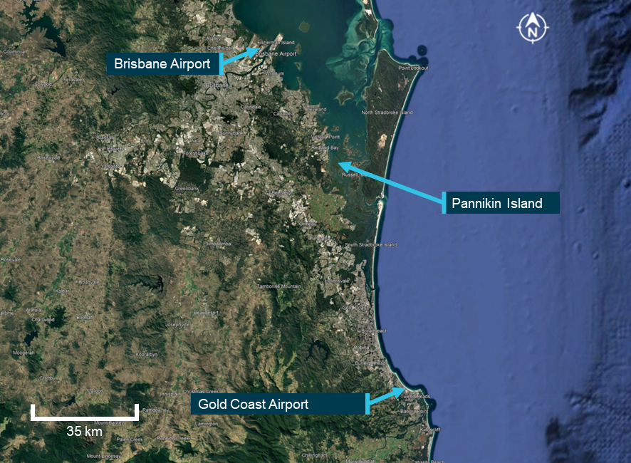
Minute-by-minute wind data from the Bureau of Meteorology around the time of the accident indicated generally moderate winds with some directional variability.
Brisbane Airport observations recorded winds at 126°–143° with wind speeds of 9–13 kt, gusting to 18 kt. Similarly, Gold Coast Airport recorded winds at 150°– 208° with wind speeds of 9–14 kt, gusting to 18 kt. The accident site which was located between these two reporting stations (Figure 2) was likely subject to similar wind conditions.
Figure 2: Map showing location of weather stations and Pannikin Island
Source: Google Earth, annotated by the ATSB
The instructor stated that they checked the weather conditions before departing, and that the wind direction indicated a south‑easterly wind at about 15 kt. On arrival at Pannikin Island, they recalled that the surface wind was observed to be more southerly in direction and felt slightly stronger than 15 kt.
Downdraught
Downdraught is a vertical atmospheric condition where a current of air sinks rapidly, leading to sudden changes in conditions at ground level and can produce strong surface winds. Downdraughts can pose a significant threat to rotary aircraft, particularly while manuevering at low level. The most common causes of downdraught experienced by helicopter pilots are due to irregular terrain when combined with strong surface winds, mechanical turbulence,[7] temperature inversions or thermal convection movements.
Accident site and wreckage
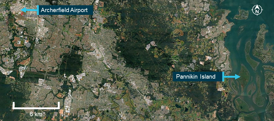
The operator conducted training over Pannikin Island, a designated training area to the south-east of Archerfield Airport. The island is one of several uninhabited islands located in southern Moreton Bay, about 56 km south-east of Brisbane (Figure 3).
The instructor recalled that the Pannikin Island training area extended from sea level to 3,500 ft. The vegetation on the island is mainly mangrove shrubland, with no buildings or power lines in the vicinity, and for this reason was used for low-level training.
Figure 3: Google Earth image of location of Pannikin Island, Queensland
Source:Google Earth, annotated by the ATSB
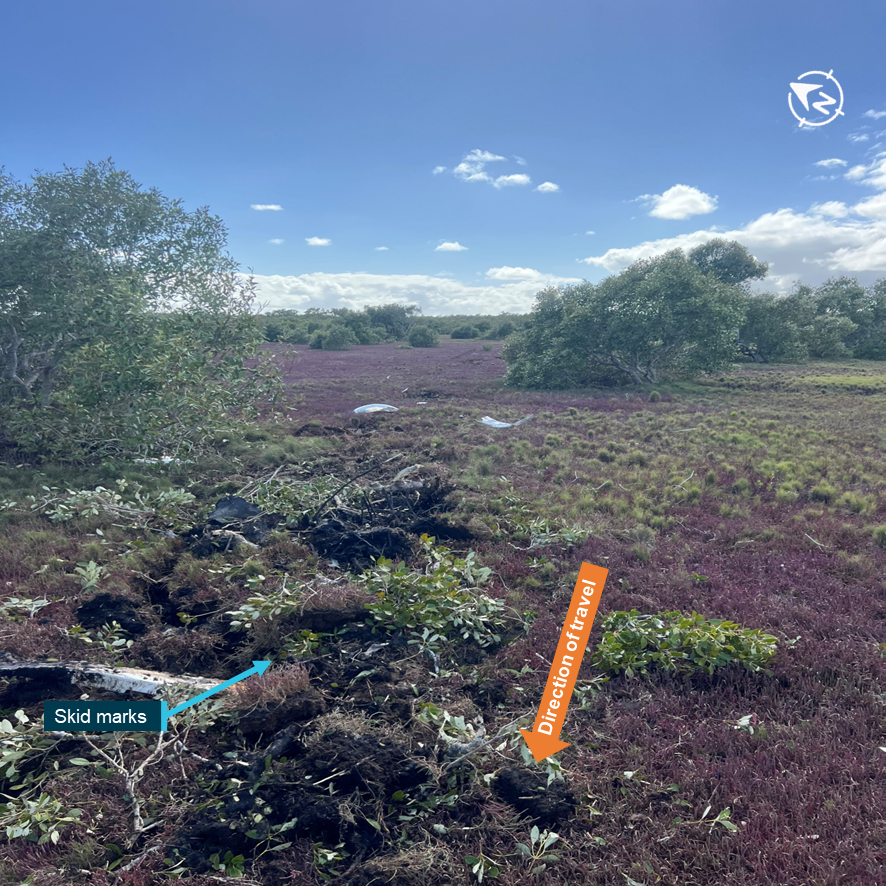
The initial ground contact of the helicopter indicated a high‑speed, upright skid contact before further loss of directional control and impact (Figure 4). The student and instructor reported that the speed on touchdown of the helicopter was about 70 kt and was consistent with the skid mark length.
Figure 4: Photograph of impact site
Source: Student
After further impacting mangrove trees, the tail rotor assembly, including tail rotor, gearbox vertical and horizontal stabiliser, separated from the cabin and was reported as being located about 15 m north of the wreckage (Figure 5) and was largely intact.
Figure 5: Photograph of main and tail rotor wreckage at accident site
Source: Student
Post-accident aircraft examination
The operator’s chief engineer carried out an inspection of the helicopter at the accident site before the wreckage was removed. The engineer reported that their examination found no evidence of mechanical issues that could have led to the accident.
Recorded data
There was no onboard data recording on the helicopter to determine the flight control inputs and their effect on the helicopter during the accident.
Recorded radar data was available of the helicopter in the training area, however due to the low-level nature of the operation, this was intermittent.
Helicopter exercises and operator’s procedures
Helicopter pilots are taught a range of manoeuvres as part of their training and licensing requirements. These are typically categorised as either normal, advanced or emergency procedures and are detailed by the Civil Aviation Safety Authority (CASA) for different licence levels and ratings.
In addition to the standard syllabus for advanced emergencies (e.g. autorotation, tail rotor failure), advanced procedures that are not required for the CPL-H may be introduced by flight instructors to extend a student’s capability and confidence. The approved Civil Aviation Safety Regulation (CASR) Part 141 operator exposition did not include torque turns as a requirement to obtain a CPL-H.
Pre-flight briefing
Briefings prior to a flying lesson are an essential part of flight preparation and represent an opportunity to gather, mentally prepare and organise the structure of the upcoming training flight. It is also an opportunity to assess the potential risks and hazards that might arise during normal and emergency operations. Discussion on the procedures to be used in the case of unexpected events disrupting the planned flight operations are also covered, and this prepares and sets student expectations for the lesson.
While pre-flight briefings were normally conducted before each lesson covering the intended lesson sequences, on this occasion the instructor considered a detailed briefing was unnecessary due to the student’s previous experience. Before departure, the instructor and student recalled a brief discussion focused primarily on the weather, but this did not include a formal briefing covering the planned exercises and potential risks.
The intent of the lesson was to consolidate the student’s prior training and both pilots recalled that the session was to refresh and consolidate advanced emergency procedures.
Low-level operations
A low-level operation is defined by regulation 61.010 of CASR as flight at a height lower than 500 ft AGL, other than when taking off or landing, and is not permitted unless the circumstances outlined in sub regulation 91.267(3) of CASR apply to the flight and the pilot is authorised under Part 61 to conduct the operation. Low‑level operations can introduce increased risk for all pilots as the proximity to terrain and reduced margin for recovery intensify the consequences of any deviation from the expected performance. There is also an increased susceptibility to adverse environmental conditions for students with less experience.
Torque turns
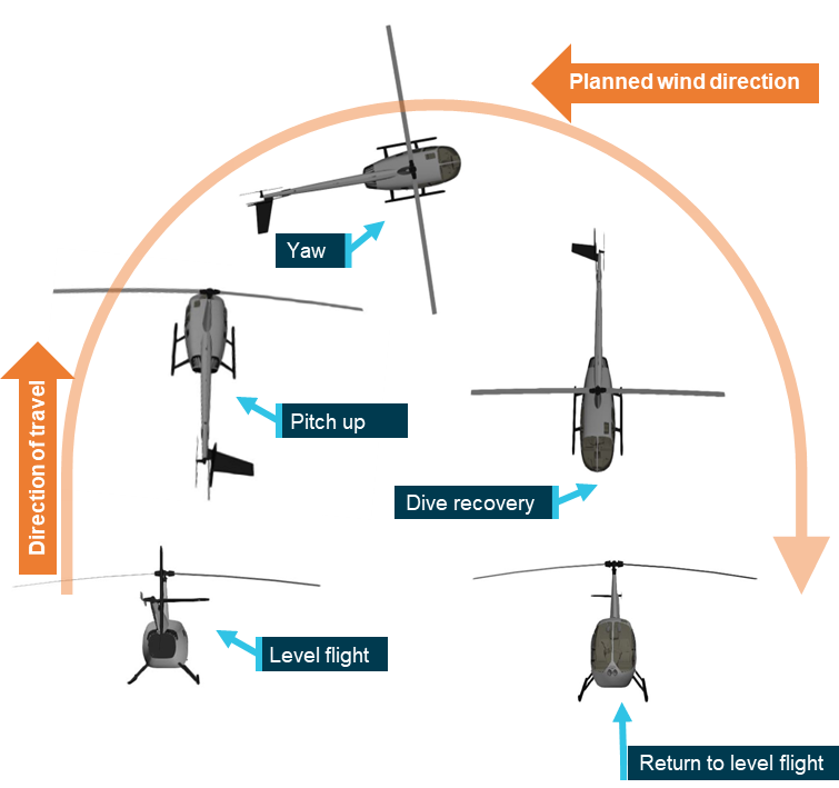
A torque turn is an advanced manoeuvre to quickly complete a 180° change in direction of flight (Figure 6). The manoeuvre begins with a pitch upwards to reduce forward airspeed followed by an application of power to increase altitude. As airspeed decreases, aerodynamic stability is reduced and the increased torque induces yaw.[8] This yaw is used to initiate the turn which continues until the helicopter is facing the opposite direction. Once the turn is complete, the pilot regains airspeed, eases out of the dive and resumes level flight in the new direction.
Figure 6: Helicopter torque turn flight sequence
Source: ATSB
The student reported that their request to conduct the torque turn training was driven by their desire to seek employment in the agricultural domain (aerial application and dispensing operations) after obtaining their commercial licence. They recalled completing several turns successfully before the accident turn.
However, in response to the draft report, CASA stated that torque turns are not common and are actually avoided in rotorcraft aerial application and dispensing operations, in favour of accurately flown and coordinated procedure turns (see below).
No official height for conducting torque turns in training is provided by CASA, however general guidance provided for starting more advanced or complex manoeuvres is to begin at higher altitudes and reduce once competence is gained.
Procedure turns
A procedure turn is a standard course reversal manoeuvre used to change the helicopter’s direction. ICAO defines the manoeuvre as a turn made away from a designated track followed by a turn in the opposite direction to permit the aircraft to intercept and proceed along the reciprocal of the designated track. Procedure turns may be designated as being made either in level flight or while descending, according to the circumstances of each individual approach procedure. To commence the turn the aircraft would turn off track, maintain airspeed, conduct the turn and turn onto the reverse of the original course. They are sometimes referred to as ‘P turns’ as the flight track looks like a ‘P’ from above.
The Part 61 Manual of Standards competency standards for unit AA2 – Helicopter aerial application operation, specifically requires procedure turns in element AA2.6 – Manipulate helicopter at low level:
(a) manoeuvres helicopter at all speeds below 500 ft AGL, up to and not beyond the limits of the flight-manoeuvring envelope, without exceeding the operating limitations of the helicopter;
(b) conducts coordinated, smooth procedure (P) turns with varying power settings.
Operator low-level training
In line with the CASA requirements, the operator’s exposition stated that procedure turns were required for advanced low-level training and detailed amongst other manoeuvres that the height range for the conduct of these was between 200 ft and 5 ft AGL. However, no specific minimum height was declared for procedure turns.
There was no reference for torque turns in the operator’s exposition.
Search and rescue
Search and rescue time (SARTIME) is the time nominated by a pilot for the initiation of search and rescue action. Any person deemed to be a responsible person can hold SARTIME for a pilot’s safe arrival.
There was no regulatory requirement for the operator’s local training flights under CASR Part 91 for a SARTIME, however the absence of a formal flight following process during flight training may have implications for the operator’s duty of care during the operation.
The operator’s head of operations (HOO) reported that a range of tracking systems were used across the operator’s fleet, including satellite trackers and transponders. These devices allowed staff to monitor the location of helicopters during flight and, if a helicopter did not return within an expected time, its position could be quickly determined. A television screen located in the operator’s office displayed tracking data, however, no personnel were specifically assigned to monitor return times or to observe the radar feed.
Many of the flight training lessons were conducted from the operator’s base at Archerfield Airport, where staff could maintain direct visual oversight of helicopter movements. However, as the accident flight was early in the morning, there was only one other instructor conducting flight training and the office staff were not yet on duty.
Some helicopters in the fleet were fitted with electronic locator transmitters and others with personal locator beacons. Under CASR regulations these are mandated for flights greater than 50 NM from the departure aerodrome. The accident helicopter was fitted with a manually‑activated personal locator beacon, however the instructor reported that they were dazed immediately after the accident and did not prioritise the activation.
Safety analysis
Introduction
An instructor and a student were conducting advanced emergency training in a Robinson Helicopter Company R22 (R22) helicopter, registered VH-8BW, at Pannikin Island in Moreton Bay, Queensland. Near completion of the commercial helicopter pilot lesson, the instructor and student agreed to conduct torque turns, an advanced helicopter handling manoeuvre that was outside of the training syllabus. After conducting several torque turns, the helicopter entered an increased low nose attitude during recovery at low altitude which resulted in a collision with terrain and dynamic rollover.
This analysis will consider decision‑making of the instructor and student and the instructor’s recovery as factors in the accident.
Decision-making
Instructing is a complex task and flight instructors must balance the benefit to the student’s learning and experience with safe margins of operation in a dynamic and sometimes rapidly changing environment.
The decision to conduct torque turns was only discussed between the instructor and the student during the flight.
Instructors consider several factors such as student performance, recent progress and training objectives when making in‑flight decisions to alter or vary the training flight plan. While instructors can adapt lessons to suit the student’s progress, deviations from planned activities should be underpinned by clear safety considerations, briefings and effective risk management.
Effective instructional decision-making balances educational value with operational risk. The instructor assessed the student to be capable of performing the manoeuvres based on their recent progress and performance during the lesson and having completed many previous training hours together. However, this assessment was done during the training flight, limiting the time available for the instructor to fully consider the benefits and risks (including height to conduct the training – see below).
The benefits of conducting a pre-flight brief of the lesson, especially where training operations are conducted in emergencies is well-established. Such a briefing reaffirms standard operating procedures, promotes predictable behaviour, and sets expectations (Sumwalt and others, 2010).
The torque turns were not part of the syllabus and were not necessary for the lesson. However, if the decision to conduct them had been agreed before flight, this would have allowed for a full ground briefing to establish the torque turn procedures, discuss the conduct of the manoeuvre and ensure a common understanding of how the practise turns would be conducted.
Manoeuvre height
Torque turns were outside of the advanced emergency lesson for the operator’s commercial pilot training syllabus and consequently no procedure was identified in the training materials for conducting them during training. The absence of a defined procedure places the reliance on the instructor to become the risk control. In this case there was an increase in risk as the manoeuvre was conducted at a height that reduced the available safety margin and limited the opportunity for recovery when the helicopter entered an undesired state. By contrast, if the manoeuvre had been initiated at a higher altitude, the increased height would have provided more time for the student and instructor to identify, intervene and recover from the undesired aircraft state. Increased altitude when practising a high-risk manoeuvre with a student would allow time for corrective control inputs from the instructor to avoid collision with terrain.
Beginning the low-level torque turn exercise at 50 ft AGL, rather than starting higher and working down as the student’s capability improved, increased operational risk.
Instructor recovery
During the torque turn, the helicopter exited the manoeuvre in a lower than expected nose attitude. Instructor intervention is a critical control in flight training and is often the final opportunity to regain control of the helicopter. Although the instructor took over control as soon as they recognised the rapid descent rate, the low height on exiting the torque turn limited the time available to arrest the descent before ground contact occurred. Environmental conditions may have further reduced the safety margin and complicated the low-level recovery.
Due to the high speed of the helicopter and approaching vegetation, the instructor likely attempted to slow the helicopter using rear cyclic (as would be normal practice when airborne), however, after skid contact with the ground in an upright attitude, this likely resulted in the main rotor disk flexing and making contact with the tail boom. This resulted in the severing of the tail boom by the main rotor blades, loss of torque control and the front left skid digging into soft soil, leading to a dynamic rollover.
SARTIME
The operator had no formal process for monitoring the return of training flights. While many operations were conducted within line-of-sight or in close proximity to the operator’s base, this informal system provided limited assurance that an overdue returning training flight outside of the airport vicinity would be identified. In this case, had the crew been more seriously injured or rendered unconcious, the lack of formal SARTIME and flight following would likely have delayed the initiation of search and rescue efforts and substantially reduced survivability.
Findings
ATSB investigation report findings focus on safety factors (that is, events and conditions that increase risk). Safety factors include ‘contributing factors’ and ‘other factors that increased risk’ (that is, factors that did not meet the definition of a contributing factor for this occurrence but were still considered important to include in the report for the purpose of increasing awareness and enhancing safety). In addition ‘other findings’ may be included to provide important information about topics other than safety factors.
These findings should not be read as apportioning blame or liability to any particular organisation or individual.
From the evidence available, the following findings are made with respect to the collision with terrain involving Robinson R22 Beta, VH-8BW, 29 km north of Southport Aerodrome, Queensland, on 26 February 2025.
Contributing factors
While conducting commercial training consolidation for low‑level and emergency procedures, the instructor and student agreed to conduct torque turns, which were outside the lesson plan and training syllabus.
Without a procedure, the instructor conducted the exercise at an inappropriate low height, which increased risk and did not allow for a margin of error.
During the torque turn exercise the helicopter exited the turn in a lower than expected attitude. The instructor assumed control but was unable to prevent a collision with terrain.
Other findings
The operator had no formal process for monitoring the return of training flights. This would delay search and rescue response and reduces post-impact survivability of aircraft occupants in the event of life-threatening injuries.
Safety actions
Whether or not the ATSB identifies safety issues in the course of an investigation, relevant organisations may proactively initiate safety action in order to reduce their safety risk. All of the directly involved parties are invited to provide submissions to this draft report. As part of that process, each organisation is asked to communicate what safety actions, if any, they have carried out to reduce the risk associated with this type of occurrences in the future. The ATSB has so far been advised of the following proactive safety action in response to this occurrence.
Safety action addressing SARTIME
The operator has implemented a SARTIME procedure using an application for shared messaging between instructors and staff. For each flight, the instructor records the helicopter registration, flight details and estimated time of arrival back at base. Any delays are communicated through the group and landings are confirmed upon arrival at base or the intended destination. The procedure is documented on the pre-flight board.
Sources and submissions
Sources of information
The sources of information during the investigation included the:
instructor of the accident flight
student pilot
operator CEO and HOO
Civil Aviation Safety Authority
Bureau of Meteorology.
References
Sumwalt, R. L. Lemos, K. A., & McKendrick, R. (2019). The accident investigator’s perspective. In Crew resource management (pp. 489-513). Academic Press.
Submissions
Under section 26 of the Transport Safety Investigation Act 2003, the ATSB may provide a draft report, on a confidential basis, to any person whom the ATSB considers appropriate. That section allows a person receiving a draft report to make submissions to the ATSB about the draft report.
A draft of this report was provided to the following directly involved parties:
instructor of the accident flight
student pilot
operator CEO and HOO
Civil Aviation Safety Authority.
Submissions were received from:
instructor of the accident flight
operator CEO and HOO
Civil Aviation Safety Authority.
The submissions were reviewed and, where considered appropriate, the text of the report was amended accordingly.
Purpose of safety investigations
The objective of a safety investigation is to enhance transport safety. This is done through:
identifying safety issues and facilitating safety action to address those issues
providing information about occurrences and their associated safety factors to facilitate learning within the transport industry.
It is not a function of the ATSB to apportion blame or provide a means for determining liability. At the same time, an investigation report must include factual material of sufficient weight to support the analysis and findings. At all times the ATSB endeavours to balance the use of material that could imply adverse comment with the need to properly explain what happened, and why, in a fair and unbiased manner. The ATSB does not investigate for the purpose of taking administrative, regulatory or criminal action.
About ATSB reports
ATSB investigation reports are organised with regard to international standards or instruments, as applicable, and with ATSB procedures and guidelines.
Reports must include factual material of sufficient weight to support the analysis and findings. At all times the ATSB endeavours to balance the use of material that could imply adverse comment with the need to properly explain what happened, and why, in a fair and unbiased manner.
An explanation of terminology used in ATSB investigation reports is available here. This includes terms such as occurrence, contributing factor, other factor that increased risk, and safety issue.
Publishing information
Released in accordance with section 25 of the Transport Safety Investigation Act 2003
Ownership of intellectual property rights in this publication
Unless otherwise noted, copyright (and any other intellectual property rights, if any) in this report publication is owned by the Commonwealth of Australia.
Creative Commons licence
With the exception of the Commonwealth Coat of Arms, ATSB logo, and photos and graphics in which a third party holds copyright, this report is licensed under a Creative Commons Attribution 4.0 International licence.
The CC BY 4.0 licence enables you to distribute, remix, adapt, and build upon our material in any medium or format, so long as attribution is given to the Australian Transport Safety Bureau.
Copyright in material obtained from other agencies, private individuals or organisations, belongs to those agencies, individuals or organisations. Where you wish to use their material, you will need to contact them directly.
[1]Autorotation is a condition of descending flight where the main rotor of a helicopter is driven only by aerodynamic forces with no power from the engine due to engine failure or deliberate disengagement.
[2]A torque turn is an advanced manoeuvre involving rapid yaw using engine torque to change direction.
[3]Cyclic: a helicopter control used to tilt the rotor disc allowing the aircraft to move in a particular direction.
[4]A stinger, otherwise known as the tail skid, is a protrusion at the rear of a helicopter that is intended to protect the tail boom when landing.
[5]Dynamic rollover: a helicopter is susceptible to a lateral rolling tendency. It begins when the helicopter starts to pivot laterally around its skid or wheel while in contact with the ground. Once the critical angle, typically around 5–8° is exceeded, the helicopter rolls over, often too quickly for any corrective pilot action.
[6]Collective: a primary helicopter flight control that simultaneously affects the pitch of all blades of a lifting rotor. Collective input is the main control for vertical velocity.
[7]Mechanical turbulence occurs when wind flows over obstacles like mountains or buildings, disrupting smooth airflow and creating bumpy flight experiences.
[8]The motion of an aircraft about its vertical or normal axis.
Occurrence summary
Investigation number
AO-2025-011
Occurrence date
26/02/2025
Location
29 km from Southport Aerodrome
State
Queensland
Report release date
04/11/2025
Report status
Final
Investigation level
Short
Investigation type
Occurrence Investigation
Investigation status
Completed
Mode of transport
Aviation
Aviation occurrence category
Collision with terrain, Flight control systems, Loss of control, Weather - Other
Occurrence class
Accident
Highest injury level
Serious
Aircraft details
Manufacturer
Robinson Helicopter Co
Model
R22 Beta
Registration
VH-8BW
Serial number
4200
Sector
Helicopter
Operation type
Part 141 Recreational, private and commercial pilot flight training
On 27July 2024, the pilot of a Eurocopter AS350 departed a mining airport in Western Australia. The helicopter flew about 10 NM to the east and landed at a pre-determined location to collect a team of surveyors. On landing, the pilot of the helicopter received a message from the surveyors who advised they required another hour at the site, the pilot then shut the helicopter down. Noting the strong and gusting wind conditions, they tied the main rotor blades down to prevent blade sailing or bouncing, they also noticed the tail rotor was “see-sawing” aggressively. The pilot then installed the tail rotor gust lock pin, which dampens the movement of the tail rotor when the aircraft is stationary and prevents any damage, and conducted their usual turnaround inspection of the helicopter.
Once the survey team had returned to the helicopter, the pilot untied the main rotor tie‑downs and stored them in the helicopter’s rear locker. From the rear locker the pilot conducted a pre-flight walk-around to the front of the aircraft, however did not inspect the tail rotor or remove the tail rotor gust lock pin. The pilot reported they had not previously installed the gust lock pin in the field and the deviation from their standard aircraft configuration contributed to the occurrence.
The pilot conducted normal pre-start and pre-departure checks, they noted an unusual, mild vibration from the main rotor and tail rotor which they presumed to be caused by the strong gusting wind from the 3 o’clock position. The pilot took off and immediately became aware that the pedals were jammed in a neutral position and determined the cause to be the tail rotor gust lock pin still being in place.
The pilot then briefed the passengers regarding the nature of the emergency and the plan to divert back to the original take-off airport. The pilot telephoned the airport reporting officer via the Bluetooth in their helmet to advise of the emergency.
They then conducted the emergency procedure for jammed pedals and landed on the runway without incident. The pilot reported the landing was a gentle zero speed, no hover landing.
The helicopter was positioned on the runway preventing any further arrivals or departures until it could be removed. There was no operational impact to the airport whilst the helicopter was positioned on the runway.
The pilot advised the ATSB that there was no visual damage to the structure of the aircraft or to the tail rotor assembly. An engineering inspection confirmed no damage to the aircraft; however the gust lock pin was deformed in the horizontal axis. Due to this deformation, the manufacturer requested that the following parts be replaced:
tail rotor pitch change spider bearing
tail rotor control lever
all tail rotor control attaching hardware aft of the tail rotor control rod (long shaft) for pitch links, lever etc.
Safety action
The pilot’s awareness in determining the cause of the jammed pedals and their following actions to conduct a safe emergency landing at the airport, prevented the loss of control of the aircraft and potential injuries or fatalities to the occupants.
Safety message
This incident highlights the importance of a thorough pre-flight inspection, ensuring pilots follow a systematic procedure as per the aircrafts flight manual. If interrupted, it is best practice to start again from the beginning of the inspection to ensure nothing is missed.
As per the flight manual pilots should always check flight controls for free movement prior to engine start.
Further, anytime a pilot detects an unusual control feedback prior to take-off, it is recommended that pilots shut down the aircraft, complete a thorough inspection and contact the operators engineering provider to discuss the issue.
The operator reported that they have sought a customisation of the “remove before flight” tapes used on the tail rotor gust lock pin to increase their length and therefore visibility.
About this report
Decisions regarding whether to conduct an investigation, and the scope of an investigation, are based on many factors, including the level of safety benefit likely to be obtained from an investigation. For this occurrence, no investigation has been conducted and the ATSB did not verify the accuracy of the information. A brief description has been written using information supplied in the notification and any follow-up information in order to produce a short summary report, and allow for greater industry awareness of potential safety issues and possible safety actions.
On the morning of 27 April 2022, a Boeing 737-800 registered VH-YFZ and operated by Virgin Australia Airlines departed from Gold Coast Airport, Queensland. Immediately after take-off, the pilot noticed the aircraft tended to roll to the right, and trimmed the rudder to keep wings level. The aircraft no longer required trim when the flaps were retracted for cruise, but the issue returned when the flaps were extended for landing. There were no warnings of flap skew or asymmetry provided to the flight crew.
A walk-around inspection following the flight revealed that left outboard aft flap had not completely retracted. A subsequent engineering inspection found several components in the aft flap actuation system had failed.
What the ATSB found
The ATSB determined that a pre-existing fatigue crack progressed through the aft flap’s inboard programming roller cartridge resulting in component failure. This cartridge held a roller that guided the aft flap during extension and retraction. The failed cartridge affected aft flap performance when flaps were deployed, and resulted in the aircraft’s tendency to roll to the right. While it could not be determined precisely when the cartridge failed, it likely occurred at some point following touchdown during the previous flight, but before take-off on the incident flight.
Boeing specified a general visual inspection of the left outboard flap. On VH-YFZ, this inspection last occurred in October 2020, with no defects found. It could not be determined whether the fatigue crack was present at the inspection. Ten other instances of cracking and/or failure at the programming roller were reported to Boeing between 2017 and 2022. At least 6 of these were old enough to have been inspected several times prior to failure. Significantly, the area in which the fatigue cracks developed was not included in a detailed inspection that Boeing specified for the flap actuation system.
What has been done as a result
While it was identified that failure of this component would not significantly affect the controllability of the aircraft, the ATSB issued a safety recommendation to The Boeing Company that it take safety action to increase the detection of fatigue cracks in the roller cartridges of 737‑800 prior to failure.
Safety message
While modern aircraft provide pilots with detailed system information, certain malfunctions can still occur without detection, such as in this occurrence. While the flight crew were not able to determine the root cause of the roll tendency during flight, they maintained continual awareness of the issue, reacting quickly and appropriately to maintain control of the aircraft.
The occurrence
At 0706 local time on 27 April 2022, a Virgin Australia Airlines Boeing 737-800 registered VH-YFZ departed from Gold Coast Airport en route to Sydney. It was the first flight of the day for both the aircraft and flight crew. As per normal operating procedures, the aircraft took off with flaps partially deployed. Shortly after take-off, the pilot flying noticed that the aircraft had a tendency to roll to the right and added 1.5° of left rudder trim[1] to keep the wings level. When the flaps were retracted during climb, the rudder was trimmed back to 0°.
As the aircraft climbed through 10,000 feet, the cabin manager mentioned to the flight crew that a ‘muffled rumble’ could be heard coming from the left side of the aircraft. In the cockpit, the captain could perceive a sound, but thought it to be more of a ‘whine’. The flight crew discussed potential sources for the noise, and attributed it to some slight damage on one of the engine fan blades that had been previously identified and logged for maintenance.
The autopilot was engaged for most of the flight, including during flap deployment for the first portion of the approach into Sydney Airport. As the aircraft intercepted the localiser[2] track and the wings levelled out, the pilot flying noticed that the control column was substantially laterally displaced. The pilot disengaged the autopilot and immediately felt the aircraft rolling to the right. The pilot used the aileron to keep wings level as the rudder was trimmed back to 1.5° to the left. The flight crew landed the aircraft without further incident.
Once the passengers had disembarked, one of the flight crew conducted a walk-around inspection of the aircraft and noticed that part of the left outboard aft flap had not completely retracted after landing, resulting in a skew (Figure 1). The flight crew received no flap asymmetry or flap skew warnings throughout the flight. A subsequent engineering inspection identified component failures in the left outboard aft flap actuation system.
Figure 1:The skewed left outboard aft flap of VH-YFZ after landing in Sydney
Source: Flight crew, annotated by the ATSB
Context
Flap actuation system and damage description
The aircraft’s trailing edge flap system contains an outboard aft flap nested within a larger main flap when fully retracted. Upon extension, a ball screw and gimbal transmit forces into pushrods rods to deploy the aft flap. The aft flap is guided by several rollers along tracks connected to the main flap. The roller on the inboard edge of the flap is known as the inboard programming track roller. In this occurrence, a component known as a ‘cartridge’ securing this roller to the aft flap failed (Figure 2).
Figure 2: The failed cartridge (left) and example cartridge highlighted in blue (right)
When the damaged programming roller cartridge was found, the section still attached to the aft flap had caught on the underside of the main flap, damaging the skin (Figure 3, left). This contact with the main flap prevented the aft flap from retracting correctly. The other section of the cartridge, including the roller, detached from the aircraft and was not recovered. In addition to the damaged programming roller cartridge, one of the pushrods in the flap actuation system was also found to have failed (Figure 3, right).
Figure 3: The programming roller cartridge obstructed by the main flap (left) and the failed pushrod (right)
Source: Virgin Australia, annotated by the ATSB
The flap skew sensor—responsible for detecting asymmetry or skew in the flaps—tracked the position of the gimbal as the flaps extended and retracted. However, the failed cartridge and pushrod had no effect on the gimbal, so asymmetry or skew in the aft flap could not be detected.
Component examination
The failed inboard programming roller cartridge and pushrod were sent to the ATSB for detailed technical examination. Two regions of fatigue cracking were identified in the cartridge (Figure 4). These were separated by deformation resulting from contact with the main flap. Outside of these two regions, the fracture surfaces appeared to be consistent with overstress, with no evident fatigue cracking.
Figure 4: The fracture surface of the cartridge, with the entire component inset
Source: ATSB
The two fatigue regions were examined using optical microscopy (Figure 5). Red arrows indicate the most obvious beachmarks—evidence of crack progression. The orientation of the beachmarks suggest the crack propagated in the direction indicated by the orange arrows. The crack origin was likely near the bottom of fatigue region 1. It was either obscured by smearing of the metal, or was on the section of cartridge that was not recovered. Blackening and corrosion pitting on the lower half of fatigue region 1 indicate that this portion of the crack had been present for some time.
Figure 5: Fatigue regions 1 (left) and 2 (right) on the failed programming roller cartridge
Red arrows point to observed beachmarks. Orange arrows indicate the direction of crack propagation.
Source: ATSB
A visual examination of the pushrod revealed no evidence of pre-existing damage. Localised deformation at the fractured ends was indicative of buckling/bending failure (Figure 6). This was consistent with the compressive forces it would have experienced as the aft flap become stuck during retraction.
Figure 6: Both halves of the failed pushrod
Source: ATSB
Maintenance history
The programming roller cartridge, pushrod and associated aft flap actuation system were the original parts installed when VH-YFZ was manufactured in 2017. They had acquired 6,377 flight cycles since their installation. Inspection of the roller cartridge was conducted as part of a general visual inspection of the left flap. This was scheduled every 6,000 flight cycles or every 36 months. Guidance from Boeing described this type of inspection as:
A visual examination of an interior or exterior area, installation or assembly to detect obvious damage, failure or irregularity. This level of inspection is made from within touching distance, unless otherwise specified. A mirror may be necessary to enhance visual access to all exposed surfaces in the inspection area.
This inspection was performed on-wing with flaps deployed, and last occurred on VH-YFZ in October 2020, with no defects identified.
A more detailed on-wing inspection was specified for the flap actuation system, which Boeing recommended every 12,000 flight cycles. In the associated task card, the engineer was required to perform ‘a detailed visual inspection of… inboard and outboard programming rollers’, and a diagram was provided (Figure 7). The roller cartridge was not an intended part of the inspection. This inspection had not been carried out on VH-YZF as it was not was not yet due.
Figure 7: Reference diagram for inspection of the inboard programming roller
Prior to the occurrence flight, there were no reports of aircraft handling issues related to VH-YFZ, and recorded data from the previous flight showed no significant rudder input required to keep the wings level. Walk-arounds were conducted by the captain and an engineer before the flight and no abnormalities with the flaps were reported.
Similar occurrences
At the time of writing, Boeing had received 10 reports of similar occurrences in which a skewed flap resulted from similar cracks and/or failures at the aft flap programming roller during flight operations. All of these reports were received between 2017 and 2022. In the reports where the failure mechanism was provided, some described cracking through the roller cartridge, while others reported failure of the roller itself. Six of these reports included flight cycles and, in every instance, the number of flight cycles prior to failure was between 14,000 and 29,000.
As a result of these reports, Boeing performed a safety analysis of this condition to determine whether the event presented a potential safety issue to the affected 737 fleet. As part of the study, Boeing performed an aerodynamic review of worst-case-scenario events involving the loss of different sections of trailing edge flaps, and the effect those losses would have on the pilot’s ability to control the aircraft in the roll axis. For each of the studied events involving skews or losses of the outboard aft flap, Boeing found that the aircraft remained well within the bounds of controllability by pilots, and the issue was evaluated to result in a slight increase in workload for the pilot in the worst possible case. Based on prior occurrences, Boeing determined that fleet experience aligned with that severity study, and that the rate of occurrence was less than that required by the United States Federal Aviation Administration for the level of hazard presented.
Safety analysis
Flap component failure
Detailed technical examination identified that a fatigue crack propagated through the inboard programming roller cartridge on the left outboard aft flap, eventually resulting in failure of the cartridge. It is not clear exactly when this failure occurred, although the absence of any handling issues in the previous flight suggests that the failure was likely at some point after the previous flight’s touchdown at Gold Coast Airport.
It is also likely that the aft flap was fully and properly retracted following the previous flight. As, if it had not retracted properly—due to a failed cartridge caught on the main flap—the resulting skew would probably have been detected on at least 1 of the 2 walk-around inspections conducted prior to the occurrence flight. Additionally, any degree of cartridge damage that still permitted full flap retraction would likely have been obscured by the flap mechanism and therefore not identifiable during a walk‑around. Finally, the right-rolling tendency observed while the flaps were deployed indicates that the roller cartridge failed prior to take-off, noting that no parts of the roller cartridge were found at the airport.
The failure changed the position of the aft flap, resulting in the described asymmetric performance. When the flaps were retracted for cruise, it is possible the failed cartridge caught on the main flap, preventing compete retraction. This would explain the noise heard by the cabin manager; however, the aircraft handled normally, suggesting either the flap retracted correctly or retracted sufficiently to not affect handling.
Scheduled component inspection
Blackening and pitting of the roller cartridge fracture surface suggests that the crack might have been present for some time, but it could not be determined whether any cracking was present at the last general inspection of the left outboard flap in October 2020. The cracking observed was predominantly on the side of the cartridge that abutted the roller track. It would therefore have been very difficult to observe on-wing. There have been 10 similar occurrences involving cracking and/or failure at the aft flap programming roller during flight operations. Of the 6 occurrences where the component age was reported, the aft flap actuation system was old enough to have been inspected for fatigue cracks several times prior to failure, as part of the general visual flap inspection.
The more detailed inspection for the flap actuation system was not due on VH-YFZ for another 5,600 cycles; however, on each of the 6 aircraft mentioned above the programming rollers would have been inspected at least once prior to failure. As with the general visual inspection, this detailed inspection was performed on-wing, restricting observation of the cartridge. Additionally, while the task card specified an examination of the programming rollers, the cartridges that housed them were not included.
Findings
ATSB investigation report findings focus on safety factors (that is, events and conditions that increase risk). Safety factors include ‘contributing factors’ and ‘other factors that increased risk’ (that is, factors that did not meet the definition of a contributing factor for this occurrence but were still considered important to include in the report for the purpose of increasing awareness and enhancing safety). In addition ‘other findings’ may be included to provide important information about topics other than safety factors.
Safety issues are highlighted in bold to emphasise their importance. A safety issue is a safety factor that (a) can reasonably be regarded as having the potential to adversely affect the safety of future operations, and (b) is a characteristic of an organisation or a system, rather than a characteristic of a specific individual, or characteristic of an operating environment at a specific point in time.
These findings should not be read as apportioning blame or liability to any particular organisation or individual.
From the evidence available, the following findings are made with respect to the flight control event involving Boeing 737-800, registered VH-YFZ at Gold Coast Airport, Queensland on 27 April 2022.
Contributing factors
Failure of the inboard programming roller cartridge was due to undetected fatigue cracking that occurred in an area that was not included in the detailed flap actuation system inspection. (Safety Issue)
The failed roller cartridge affected aft flap performance when flaps were deployed, resulting in a tendency for the aircraft to roll to the right.
Safety issues and actions
Central to the ATSB’s investigation of transport safety matters is the early identification of safety issues. The ATSB expects relevant organisations will address all safety issues an investigation identifies.
Depending on the level of risk of a safety issue, the extent of corrective action taken by the relevant organisation(s), or the desirability of directing a broad safety message to the aviation industry, the ATSB may issue a formal safety recommendation or safety advisory notice as part of the final report.
All of the directly involved parties were provided with a draft report and invited to provide submissions. As part of that process, each organisation was asked to communicate what safety actions, if any, they had carried out or were planning to carry out in relation to each safety issue relevant to their organisation.
Descriptions of each safety issue, and any associated safety recommendations, are detailed below. Click the link to read the full safety issue description, including the issue status and any safety action/s taken. Safety issues and actions are updated on this website when safety issue owners provide further information concerning the implementation of safety action.
Safety issue description:Failure of the inboard programming roller cartridge was due to undetected fatigue cracking that occurred in an area that was not included in the detailed flap actuation system inspection.
Sources and submissions
Sources of information
The sources of information during the investigation included:
the flight crew
Virgin Australia Airways
The Boeing Company.
Submissions
Under section 26 of the Transport Safety Investigation Act 2003, the ATSB may provide a draft report, on a confidential basis, to any person whom the ATSB considers appropriate. That section allows a person receiving a draft report to make submissions to the ATSB about the draft report.
A draft of this report was provided to the following directly involved parties:
the flight crew
Virgin Australia Airways
The Boeing Company
the Civil Aviation Safety Authority
the United States National Transportation Safety Board.
Submissions were received from:
Virgin Australia Airways
The Boeing Company.
The submissions were reviewed and, where considered appropriate, the text of the report was amended accordingly.
Purpose of safety investigations
The objective of a safety investigation is to enhance transport safety. This is done through:
identifying safety issues and facilitating safety action to address those issues
providing information about occurrences and their associated safety factors to facilitate learning within the transport industry.
It is not a function of the ATSB to apportion blame or provide a means for determining liability. At the same time, an investigation report must include factual material of sufficient weight to support the analysis and findings. At all times the ATSB endeavours to balance the use of material that could imply adverse comment with the need to properly explain what happened, and why, in a fair and unbiased manner. The ATSB does not investigate for the purpose of taking administrative, regulatory or criminal action.
Terminology
An explanation of terminology used in ATSB investigation reports is available here. This includes terms such as occurrence, contributing factor, other factor that increased risk, and safety issue.
Publishing information
Released in accordance with section 25 of the Transport Safety Investigation Act 2003
Ownership of intellectual property rights in this publication
Unless otherwise noted, copyright (and any other intellectual property rights, if any) in this report publication is owned by the Commonwealth of Australia.
Creative Commons licence
With the exception of the Coat of Arms, ATSB logo, and photos and graphics in which a third party holds copyright, this publication is licensed under a Creative Commons Attribution 3.0 Australia licence.
Creative Commons Attribution 3.0 Australia Licence is a standard form licence agreement that allows you to copy, distribute, transmit and adapt this publication provided that you attribute the work.
The ATSB’s preference is that you attribute this publication (and any material sourced from it) using the following wording: Source: Australian Transport Safety Bureau
Copyright in material obtained from other agencies, private individuals or organisations, belongs to those agencies, individuals or organisations. Where you wish to use their material, you will need to contact them directly.
[1] In a 737-800, rudder trim makes a small change to the rudder position in order to maintain coordinated flight without constant pilot input.
[2] The localiser is part of the Instrument Landing System and provides lateral position necessary to align with the runway centreline.
Section 21 (2) of the Transport Safety Investigation Act 2003 (TSI Act) empowers the Australian Transport Safety Bureau (ATSB) to discontinue an investigation into a transport safety matter at any time. Section 21 (3) of the TSI Act requires the ATSB to publish a statement setting out the reasons for discontinuing an investigation.
The ATSB commenced an investigation into a flight control system event that occurred on 25 May 2017 involving a Boeing Company 737-800, registered VH-YIJ and operated by Virgin Australia International, on a flight from Brisbane, Queensland to Wellington, New Zealand.
The captain was the pilot flying, and he was conducting the night arrival into Wellington. The weather conditions were fine, and the descent (below flight level 250) and approach were briefed to be flown with the autopilot and autothrottle disengaged for practice.
During the approach to runway 34, the flight crew progressively selected flaps 1 then flaps 15. The landing gear was selected down and then flaps 25. The right flap moved to flap 25 but the left flap initially remained at flap 15, before moving very slowly to flap 25, which was not initially detected by the flight crew. Flap 40 was then selected, however, the flaps remained in the 25 and 15+ positions.
While carrying out the landing checklist, the flight crew detected the flap asymmetry. The flight crew attempted to rectify the problem with various flap lever selections, which were unsuccessful. Approaching 1,000 ft, the aircraft did not meet the operator’s stable approach criteria, so the flight crew initiated a missed approach.
During the missed approach, the left flap slowly extended to flap 25, correcting the initial ‘Trailing Edge Flap Asymmetry’ to a ‘Trailing Edge Flap Disagree’ condition. The aircraft, still being manually flown, subsequently climbed above the cleared altitude of 5,000 ft (reaching 5,340 ft) and the flap limit speed was marginally exceeded on two occasions. The flight crew positioned the aircraft into a holding pattern, completed the ‘After Takeoff’ checklist and ‘Trailing Edge Flap Disagree’ non-normal checklist and briefed for a second approach to runway 34 with flaps 25.
Prior to leaving the holding pattern, the captain briefed the cabin supervisor about the situation. However, the format of that briefing was the same as what the cabin supervisor would expect for an emergency. As a result, the cabin supervisor perceived that the cabin needed to be prepared for an emergency landing, which was not the captain’s intention.
A second approach was conducted with the autopilot and autothrottle engaged to 136 ft. The aircraft landed without further incident.
Engineers later performed the required aircraft inspections. They could not reproduce the flap fault, however, replaced the left-hand trailing edge flap position transmitter as a precaution.
The ATSB obtained the operator’s investigation report, and interviewed the flight crew and the cabin supervisor. The ATSB also obtained data from the aircraft’s flight data recorder, aircraft maintenance records and relevant sections of the operator’s operations manual. Based on its review of this information, the ATSB concluded that the operator had conducted a detailed investigation and it was unlikely that further ATSB investigation would identify any systemic safety issues.
The ATSB noted that, although there were flight crew errors made during the approach and the subsequent missed approach, the missed approach was conducted at an appropriate time. In addition, while the cabin crew conducted the cabin preparation drill for a non-normal landing when it was not required, doing so was an example of the operation ‘failing safe’ rather than increasing risk.
The operator has subsequently used this incident as a basis for some recurrent training for its flight crew and cabin crew. Consequently, the ATSB has discontinued this investigation.
On the morning of 2 August 2017, the pilot of a Robinson R22 Beta II helicopter, registered VH‑HGU and operated by Cloncurry Mustering Company, departed Cloncurry Airport, Queensland, on a ferry flight in preparation for an aerial mustering operation. About 3 minutes after take-off, the pilot experienced a loss of control and the helicopter broke-up in-flight. The helicopter collided with terrain about 7 km north-north-west of Cloncurry. The pilot, who was the only occupant, was fatally injured and the helicopter was destroyed.
What the ATSB found
The ATSB found that the helicopter had recently undergone a 2,200-hour overhaul and this was the first commercial flight since that time.
The on-site examination established that the bellcrank in the helicopter cyclic control assembly was missing a fastener, which allowed the assembly to disconnect in-flight. The ATSB concluded that it was likely that the fastener’s self-locking nut was either not reinstalled or it was inadequately torqued during the overhaul. While it could not be determined what had occurred to result in this condition, it was noted that Cloncurry Air Maintenance (CAM) did not use the work-pack to record and track all maintenance activities during the overhaul, which extended over a period of almost 4 months.
The ATSB noted that, in the years leading up to the accident, the CAM workforce structure had changed in a manner that reduced the levels of its qualifications and experience. In the month leading up to the accident, the CAM workforce was operating at a very high workload, which likely exceeded their workforce capability and reduced the chief engineer's capacity to oversight maintenance activities.
Cloncurry Air Maintenance (CAM) had limited internal independent oversight of maintenance activities to evaluate its quality performance. The organisation was subject to both contracted and regulator audit activities in the years leading up to the accident. The ATSB reviewed two of the work-packs sampled during the audits and noted that discrepancies in their maintenance documentation practices were visible to the auditors. However, the auditors had not identified any issues associated with those practices, and therefore, the audits were of limited benefit to CAM.
It was also established that CAM were re-using the MS21042L-series nuts on critical fasteners without replacing them with D210-series corrosion resistant nuts in accordance with the manufacturer's instructions. However, the ATSB also found that the re-use of self-locking nuts was a common and accepted industry practice.
What's been done as a result
Cloncurry Air Maintenance have improved their maintenance practices, which has included progressive certification for tasks, adopting the helicopter manufacturer’s checklists for their inspections, removing all untracked MS-series self-locking nuts from stores, and completing inspections of the flight controls on all the Cloncurry Mustering Company helicopters with nil defects reported.
In March 2019, the Australian Transport Safety Bureau issued a safety advisory notice advising all Australian maintenance personnel for Robinson helicopters to ensure that before re-using a self‑locking nut, that the correct part number is fitted, and that the D210-series corrosion-resistant nuts are used for reassembly of critical fasteners in accordance with the Robinson Helicopter Company instructions for continued airworthiness.
As a result of this accident and other investigations by the Civil Aviation Safety Authority, the regulator issued airworthiness bulletin 67-005: Robinson Helicopter Flight Controls – Independent Inspections. The bulletin highlighted the need for independent inspections to be conducted and ‘recorded consecutively with each adjustment made during rotor tracking and balancing’ activities. In addition to several recommendations, the bulletin identified several human factor elements that could impact maintenance inspection performance, and highlighted the need for extra caution to be exercised during post-maintenance flights as per the guidance provided by Robinson.
Safety message
Although verbal communications are an important method of explaining and understanding problems, they are not a reliable means for capturing essential tasks over an extended time‑period. This accident highlights the importance for maintenance organisations to consider the human factors elements associated with their practices, capture them in their documented quality control procedures, and ensure they are complied with.
Audits are essential for independently verifying the effectiveness of an organisation's processes and procedures. This accident reinforces the importance of auditors inspecting the evidence collected during an audit to ascertain whether or not the requirements are being met, specifically conformance with the relevant standards. Audits may also be used to identify potential underlying human factors issues, which may be raised as an opportunity for improvement to inform the auditee of best industry practices.
Context
Pilot information
The pilot started flying training in 2002, and had been employed by the Cloncurry Mustering Company (CMC) since 2004, and held a Commercial Pilot Licence (Helicopter) with a flight instructor rating for low‑level helicopter operations and aerial-mustering. The pilot’s most recent flight review was on 15 November 2016 in an R22 helicopter. The pilot held a Class 1 Aviation Medical Certificate with no restrictions and an expiry date of 2 February 2018. On 6 January 2017, 10,000 flying hours experience was recorded on the pilot’s medical examination questionnaire.
On 1 August 2017, the night before the accident flight, the pilot went to bed at about 2000. The next morning, the pilot left home for work at about 0530. Several colleagues spoke with the pilot between 0600 and 0700 at the company’s hangar facility at Cloncurry Airport and reported the pilot’s demeanour as normal.
From the operator’s records, the accident occurred on the pilot’s third consecutive day of flying, which included 12.2 hours flying in the previous 2 days. Prior to that period, the pilot had not flown for 8 days. The time of the accident was not in the circadian low period and did not include an extended period of duty.
Helicopter information
General information
VH-HGU was a two-seat Robinson Helicopter Company (RHC) R22 Beta II helicopter, serial number 4335, powered by a 4-cylinder, carburettor Textron Lycoming O-360-J2A engine (Figure 2). It was manufactured in 2008 and registered in Australia in July of the same year. The helicopter was added to the CMC fleet on 16 February 2017.
Figure 2: Example R22 helicopter
Source: Queensland Police Service
Drive system
Engine power is transmitted to a V-belt sheave bolted to the engine output. The V-belts transmit power to the upper sheave, which transmits power forward to the main rotor and aft to the tail rotor. Flexible couplings[2] are located at the main gearbox input (forward flexible coupling) and at each end of the tail rotor drive shaft (intermediate and aft flexible couplings).
Rotor systems
The main rotor has two blades mounted to the main rotor hub by coning hinges.[3] The hub is mounted to the main rotor shaft by a teeter hinge. Droop stops for the main rotor blades, mounted near the top of the main rotor mast, provide a teeter hinge friction restraint, which normally prevents the rotor from teetering (rocking) while stopping or starting. Elastomeric teeter stops,[4] mounted in brackets in-line with the main rotor blades, limit the teetering during normal flight conditions and will provide a damage witness mark if there is excessive teetering of the main rotor system in-flight. The main and tail rotor systems are fitted with pitch links to transmit the flight control inputs to the rotor blades.
Flight controls
Primary controls are actuated through push-pull tubes and bellcranks. Flight control operation is conventional. The tail rotor pedals change the pitch of the tail rotor blades, and therefore the thrust, of the tail rotor system, which provides directional control. The collective[5] lever controls the amount of thrust (lift) produced by the main rotor disc. Raising or lowering the collective lever will raise or lower the swashplate,[6] which will alter the pitch on both main rotor blades to increase or decrease the main rotor thrust. The collective lever also incorporates a twist grip to provide the pilot with full manual control of the engine throttle.
The cyclic[7] control tilts the main rotor disc to point the rotor thrust in the desired direction of flight. Fore-aft movement of the cyclic provides the longitudinal (pitch) control of the main rotor disc. Forward movement will tilt it down at the front and up at the back, and aft movement will tilt it up at the front and down at the back. There is a single push-pull tube connection to the swashplate at the rear of the main rotor mast to provide the pitch control. Left-right movement of the cyclic provides lateral (roll) control of the main rotor disc. There are two push-pull tubes connected to the swashplate, either side of the main rotor mast, to tilt the disc left or right.
Recent maintenance history
The helicopter had accumulated about 4,365 hour’s total time-in-service at the time of the accident. When CMC acquired VH-HGU, in February 2017, it had about 80 hours remaining before it was due for its second 2,200-hour overhaul. Therefore, the operator’s maintenance organisation, Cloncurry Air Maintenance (CAM), completed a 100-hour inspection at the time of the acquisition and the helicopter was operated by CMC until the 2,200-hour overhaul was started on 12 April 2017.
The 2,200-hour overhaul involved the disassembly, inspections, reassembly and checks of the helicopter. All flight control push-pull tubes were sent for non-destructive testing and found serviceable. The helicopter was reassembled and a weight and balance, and fuel calibration was completed. The flight controls were rigged and then the helicopter was subject to a 100-hour inspection before a ground run, track and balance[8] of the main rotors, and autorotation RPM check were completed on 28 July 2017.
On 31 July 2017, a 15-minute local area flight was conducted to confirm the serviceability of the helicopter. Following that flight, CAM staff certified for all the tasks in the 2,200-hour overhaul work-pack, including independent inspections[9] of the engine and flight controls, and issued the maintenance release.[10]
The next time the helicopter was operated was the accident flight.
Loading and performance
The ATSB’s calculations indicated the helicopter was within the prescribed weight and balance limits for the flight. Using the local environmental conditions, the out-of-ground‑effect[11] hover performance weight was within limits at the helicopter’s certified maximum all-up-weight of 622 kg.
Meteorological information
The weather conditions recorded at Cloncurry Airport at 0700 included a wind speed of 1 kt from 100°, a temperature and dewpoint[12] of 14 °C and 5 °C respectively, and a QNH[13] of 1015 hPa. The Cloncurry aerodrome forecast[14] for the period from 0400 to 1600 included a wind speed of 6 kt from 170° and CAVOK[15] conditions. Given the insignificant conditions, the ATSB determined that it was very unlikely that the weather contributed to the circumstances of the accident.
Global positioning system data
The pilot’s Garmin GPSMAP196 navigation device was recovered from the wreckage for examination and analysis by the ATSB. The global positioning system (GPS) had several track logs, which included the accident flight and a previous mustering flight.[16]
Figure 3 depicts the helicopter’s GPS track from take-off to the accident site, and Figure 4 depicts the position of the main wreckage relative to the last reliable GPS data point and vicinity to the powerlines. Table 1 provides the data points for the accident flight. The ATSB considered the final data point (14), which was beyond the accident site, to be an unreliable point for the purpose of analysis as it very likely represented a predictive point.[17]
Figure 3: Accident flight GPS track
Source: Google Earth, annotate by the ATSB
Figure 4: Accident site datum relative to the last reliable GPS data point
Source: Google Earth, annotated by the ATSB
From Table 1, the changes in altitude and vertical speed were all positive from the departure point to the last reliable data point (13). In addition, the average ground speeds between the data points were relatively stable leading up to point 13. This suggested the helicopter had a reasonably steady climb flight profile. At point 13, the helicopter was about 279 ft above the local terrain, and about 82-148 ft above the height of the Ernest Henry powerline towers.[18]
The pilot was a patient of the Cloncurry Flinders Medical Centre since 2005, which included flight crew medical examinations by the local designated aviation medical examiner (DAME). In 2011, after a diagnosis of mild hypertension, the pilot started a prescribed daily dose of 150 mg Irbesartan.[20]
Post-mortem and toxicology results
The post-mortem examination established that the pilot received extensive injuries associated with a rapid deceleration and the cause of fatality was ruled as multiple injuries as a result of the accident. The examination also found 75 per cent eccentric stenosis[21] in the mid segment of the left anterior descending artery of the pilot’s heart. This was characterised as severe atherosclerosis.[22] The forensic pathologist reported:
It is theoretically possible that this may have precipitated abnormal heart rhythm leading to pilot incapacitation and subsequent accident. This scenario can be neither confirmed nor excluded on the basis of autopsy examination.
A low concentration of alcohol was detected in the blood, which was considered to be ‘likely post‑mortem contamination, probably due to decomposition’. No drugs, including Irbesartan, were detected.[23]
Specialist advice
In consideration of the forensic pathologist’s scenario, the ATSB conducted a follow-up on the pilot’s health with the Cloncurry DAME, the CASA Principal Medical Officer (PMO) and the Director of the Clinical Forensic Medicine Unit for the Queensland Department of Health.
The PMO noted the other arteries and heart were found with no discernible abnormality, therefore, the conditions had not dispersed through the cardiovascular system. The PMO also reported that it could not be determined with certainty if the pilot experienced abnormal heart rhythm unless the heart was being actively monitored. Queensland Health reported that the ‘consequences of high blood pressure as a clinical issue were not noted in the autopsy report. In particular, there was no evidence of a stroke and no indication of a heart attack’.
The Cloncurry DAME reported the dosage of Irbesartan was moderate and that it ‘would have been unlikely to cause any symptoms of hypotension causing dizziness or disorientation’. Queensland Health and the PMO reported that missing a single dose of Irbesartan would not be likely to cause any issues clinically.
Wreckage and impact information
The wreckage examination included an initial on-site inspection, followed by a review of the accident site images. The photographic review resulted in a second accident site visit to excavate the wreckage and retrieve a component of interest, which was the bellcrank from the cyclic control assembly.
Initial on-site examination
The helicopter wreckage was located amongst termite mounds, in a sparsely treed area. The main wreckage had been subject to a significant post-impact fire, which had reduced the cabin area to ash, molten aluminium, and fibreglass mat. The airframe was oriented south-east on a heading of about 140°, which was in the opposite direction to the helicopter’s recorded flight path. Small pieces of debris were scattered around the wreckage in a radius of about 20 m in most directions. The windscreen perspex was unburnt, shattered into small pieces and contained in an area of about 2 m2 just forward of the cabin area. All the major components were identified within the debris field (Figure 5).
Figure 5: Main wreckage
Source: ATSB
The airframe impacted the ground on the front left. Compression damage to the forward vertical firewall of the helicopter indicated that it impacted with a high rate of descent.
The helicopter’s main rotor disc had severed the tailcone and tail rotor driveshaft, leaving paint transfer on the driveshaft and tailcone. There were multiple strikes to tail components, which included the tail rotor hub and vertical stabiliser, generating a pattern of tail strike debris. The pattern was noted to be in a semi-circular arc on the right side of the main wreckage with respect to the direction of the GPS track. This was consistent with the helicopter tracking away from the airport and towards the powerlines at the time of the tailcone strike.
The main rotor blades exhibited rearward and upward bending, and there was no evidence of rotor blade ground strike marks or damage to the surrounding termite mounds. This was consistent with a significant loss of main rotor energy before ground impact, which was a near vertical impact. The teeter stops were destroyed by fire, but one teeter stop bracket was damaged and the associated main rotor blade spindle tusk[24] had a slight bend. This indicated the teeter stop bracket was struck by its respective main rotor blade spindle.
There was no evidence of any significant tension on the tail rotor driveshaft aft flexible coupling and little evidence of bending on the severed aft section of driveshaft (Figure 6). This indicated it was likely a power-on, high energy, main rotor strike to the tail.[25] The section of driveshaft forward of the severed section exhibited elongation and a bending overload, which indicated it was rotating during the break-up sequence. Therefore, the damage to the driveshaft was consistent with the main rotor disc striking the tail under normal engine power and rotor speed conditions.
Figure 6: Severed tail rotor driveshaft
Source: ATSB
The forward flexible coupling of the driveshaft exhibited significant tension. According to RHC, flexing of the main rotor mounts will change the angle of the input yoke of the main gearbox, which will cause the yokes at the flexible couplings to move apart. The tension on the forward flexible coupling, damage to the teeter bracket, and angle of the tailcone strike were consistent with a large rearward tilt of the main rotor disc in-flight past its normal limits.
On completion of the ATSB’s initial onsite inspection, the operator and next-of-kin buried the wreckage adjacent to the impact site.
Excavation
During the photographic review of the wreckage after the initial on-site inspection, the ATSB noted an anomaly with a flight control bellcrank (part number A958-1) in the cyclic control assembly. The fastener,[26] which attached the horizontal push-pull tube (part number A121-1) to the bellcrank, was missing. The remaining bellcrank fasteners were all attached. The missing fastener was part of the longitudinal cyclic control, which controls the fore-aft tilt of the main rotor disc (Figure 7). The RHC R22 Illustrated Parts Catalog (IPC) showed that the flight controls should be secured at the bellcrank with a National Aerospace Standard (NAS) 6604-15 bolt and D210-4 self-locking nut.[27]
Figure 7: Longitudinal cyclic control
Source: Robinson Helicopter Company, modified by the ATSB
The ATSB returned to Cloncurry in February 2018, and with the assistance of the pilot’s next‑of‑kin, the next of kin’s support persons, and the Cloncurry State Emergency Service personnel, excavated the majority of the buried wreckage and retrieved the bellcrank minus the missing fastener hardware. In addition to the bellcrank, the ATSB retrieved several pieces of resolidified metal to examine for the presence of hardware (bolt, standard washer, lockwasher, rod-end and self-locking nut).
In May 2018, the next-of-kin, who had continued excavating the remainder of the wreckage, sent a bolt with the same part number as the missing bolt (NAS6604-15) to the ATSB.[28] Following receipt of the bolt, the ATSB, in consultation with RHC and the next-of-kin, verified that all the remaining NAS6604-15 bolts were still attached to their respective assemblies.[29] This included the bolts not identified in the IPC as they are not normally accessible. As such, the bolt recovered from the excavated wreckage was considered very likely to be from the missing fastener. Figure 8 depicts the bellcrank and bolt.
Figure 8: Bellcrank with missing fastener (left) and bolt (right)
Source: ATSB (left) and next-of-kin (right)
Effect of loss of longitudinal cyclic control
The ATSB enquired with RHC about the expected response of the main rotor system to a disconnection of longitudinal cyclic control. They advised that:
During straight and level flight the A121-1 push-pull tube is under compression load. This pushes the cyclic aft [pilot’s cyclic stick]. A bungie cord is attached to the forward end of the tube (pulling aft, below the cyclic pivot point) to counteract the forces and neutralizes the loads felt by the pilot. The loads increase with airspeed.
With reference to Figure 7, a compression load on the A121-1 push-pull tube is consistent with a force tilting the main rotor disc aft and pushing downwards on the aft vertical push-pull tube. In forward flight, the advancing main rotor blade is at a higher airspeed than the retreating blade, which increases the lift on the advancing blade relative to the retreating blade. The reaction to this dissymmetry of lift is that the advancing blade flaps up and the retreating blade flaps down, which the pilot corrects with forward cyclic input as airspeed increases (Wagtendonk, 2011). Therefore, a disconnection of the longitudinal cyclic control in forward flight will result in the rotor disc tilting aft, potentially striking the tailcone.
Tests and research
Following identification that the rear fastener for the cyclic assembly horizontal push-pull tube was missing from the bellcrank, a number of items were recovered from the accident site and retained for further examination at the ATSB’s technical facilities in Canberra. The items included:
the bellcrank – part number A958-1
a bolt – part number NAS6604-15 (recovered by the next-of-kin on 16 May 2018)
metallic debris (that had melted during the post-accident fire then resolidified on cooling)
a number of loose nuts and washers
a jackshaft – part number A337-1 – including attachment nuts and bolts
the forward support assembly – part number A014-6.
A summary of the main findings from the examination is provided here, for full details of the examination refer to Appendix A – Materials examination report. The scope of the examination was to analyse the bellcrank and related components to determine how the fastener came to be missing. In addition, the metallic debris recovered from site was examined to determine if any additional fastener parts were entrapped within the solidified mass.
Bellcrank and related components
The bellcrank and torque tube yoke assembly had been subject to significant mechanical damage such that the rod ends had fractured in overstress and the left side of the yoke assembly and bellcrank plate had significantly distorted. While the distortion of the plates was similar where the fasteners remained in position, the plates had been pushed together where the fastener was missing (Figure 9). The yoke assembly also exhibited heat damage in this area, with the left side moulding around the bellcrank plate. The combination of mechanical and heat damage meant that an exemplar bolt could not be reinserted through the bellcrank.
Figure 9: Bellcrank showing deformation observed on the torque tube yoke assembly and bellcrank plates
Source: ATSB
The bolt holes where the fastener was missing did not exhibit gross deformation or elongation of the holes to indicate that the fastener assembly had been forcibly removed during the accident sequence. Yellow colouration was observed around the other bolt holes where the fasteners had remained in position. While some yellow colouration was observed around the bolt hole of the missing fastener, it was much less than for the other holes, and none was observed around the internal surfaces of the hole (Figure 10).
Figure 10: Bellcrank internal surfaces with yellow colouration
Source: ATSB
Robinson reported that the yellow residue surrounding the fasteners was from the cadmium plating on the bolts, washers and screws.[30] The remnants of cadmium plating from the fastener assembly components had melted and subsequently oxidised during the post-accident fire. The residue surrounding the bolt hole for the missing fastener indicated the missing bolt was previously torqued, resulting in a transfer of cadmium from the washer to the bellcrank. However, as there was no outward flow, or streaking, as per the remaining fasteners, RHC considered it ‘highly unlikely that the missing bolt was present during the fire’.
The combination of the above observations indicated that the missing bolt was not fitted to the bellcrank at the time of the impact with terrain and post-impact fire.
The remaining two bolts installed on the bellcrank were identified as NAS6604-15 bolts and the nuts were consistent with the MS21042L4/NAS1291 nut-type with manufacturer markings consistent with Ronson Manufacturing Inc.
Metallic debris
The metallic debris was dissolved, and a number of fasteners and other components were recovered. However, examination of the pieces did not identify any parts from the missing fastener.
Recovered bolt
The solitary bolt found on 16 May 2018 by the next-of-kin was identified as a NAS6604-15 bolt. The bolt had the same manufacturer identification (‘LFC’) as the other two bolts fitted to the bellcrank, but exhibited greater fire damage (Figure 11).
Figure 11: Comparison between the bolts removed from the bellcrank (left and centre) and the fire damaged bolt (right) subsequently recovered from the accident site
Note: The recovered bolt is shown after it had undergone ultrasonic chemical cleaning.
Source: ATSB
The recovered bolt was thermally damaged from the post-accident fire, but was otherwise in good condition with no evidence of distortion along its length or to the threads. A small groove was identified on the thread flank, which was likely from contact with a self-locking nut during installation (Figure 12).
Figure 12: Magnified image of the bolt found 16 May 2018 showing thread groove
Source: ATSB
Jackshaft
Examination of the jackshaft assembly recovered from the wreckage found that three of the four self-locking nuts had the same manufacturer markings as the nuts fitted to the bellcrank. Fire damage precluded identification of the markings on the fourth nut.
Semi-quantitative chemical analysis of the nuts was conducted using a scanning electron microscope equipped with an Oxford energy dispersive x-ray spectrometer. The analysis confirmed that all four nuts were consistent with a carbon/alloy steel. While the spectrometer cannot determine the exact amount of alloying additions, the spectrographs for the four nuts were inconsistent with the CRES (corrosion resistant – stainless steel) D210-4 nuts specified to be used by RHC. Specifically, the nickel, chromium and molybdenum additions, where detected, were not of sufficient quantities to designate the nuts as stainless steel (see Previous safety issues - self-locking nuts).
Maintenance of the cyclic control assembly
During their interviews with the ATSB in 2018, the CAM staff[31] could not recall the specific details of the work they individually performed on the cyclic control system of VH‑HGU during the 2,200‑hour overhaul. However, they were able to provide a description of the normal process they followed for the removal, inspection, installation and inspection of the cyclic control assembly. The physical process, as described by CAM staff, was consistent with the process published and described by RHC.
Removal
The removal process involved the vertical push-pull tubes being unscrewed from the bellcrank and yoke rod-ends, then the remaining components from the cyclic stick through to the bellcrank would be removed from the airframe as a single unit. After removal from the airframe, the length between the bolt holes for the horizontal push-pull tube would be measured for use during reassembly. There was no record of this measurement in the work-pack for VH-HGU, however, the maintenance manual provided a standard length that could be used for the installation.
The horizontal push-pull tube forward fastener would then be disconnected from the cyclic stick and the horizontal push-pull tube unscrewed from the bellcrank rod-end. Therefore, the bellcrank fasteners were not required to be disassembled during this part of the process. The cyclic stick is separated from the torque tube, but the bellcrank can remain attached to the torque tube with the fasteners and rod-ends fitted, as neither of these components required non-destructive testing.
Inspection
The bellcrank is inspected for cracks and corrosion, and the rod-ends are tested for axial and radial play (Figure 13). According to RHC, the play in the rod-ends can be checked without removal from their respective fastener. The CAM staff reported that the rod-ends would initially be checked for play without their removal, and then only removed for measurement with a dial test indicator if there was doubt. The chief engineer reported that the rod-end would be replaced if it had reached half the permitted tolerance as the wear will accelerate and it was preferable to replace them at the 2,200-hour overhaul, rather than at a 100-hour inspection.
Figure 13: Rod-end and spherical bearing play limits
Source: Robinson Helicopter Company, annotated by the ATSB
There was no record in the work-pack to indicate that any of the bellcrank rod-ends were replaced or disturbed for inspection. However, other than what the maintenance manual specified for the overhaul, disturbances of the flight controls were not recorded in the work-pack unless a part was replaced. Several rod-ends from other assemblies were replaced during the overhaul, and they were accounted for by a cross-check between the ‘parts list’ and ‘aircraft worksheet’ sections of the work-pack.
Installation
After removal and disassembly, the push-pull tubes and cyclic stick would then be stripped of their paint and sent for non-destructive testing. All parts for VH-HGU were found serviceable from non‑destructive testing, and on return, they were painted and re-assembled. One of the apprentices reported the cyclic assembly could be removed and installed by an individual, but it was more common to use two persons, ‘depending on what was going on’. In August 2017, the chief engineer could not recall who refitted the parts returned from non‑destructive testing. The installation was certified as having been performed by the AME (aircraft maintenance engineer). However, in February 2018, the AME could not remember anything about this work.
The AME reported that the chief engineer would normally inspect the cyclic when re‑assembled, and again when it was installed. After installation, the chief engineer would assist the AME with the rigging process and then perform an ‘inspection and make a list and get them to fix it… and then get [head engineer] in to check’. The fourth year apprentice was reportedly involved in the disassembly, reassembly and rigging, but was unsure about the first year apprentice’s involvement. The first year apprentice was reportedly involved in the disassembly, but was at trade school 1–13 July 2017, and missed some of the reassembly.
According to RHC, if the cyclic assembly is installed and the horizontal push-pull tube has the incorrect length between bolt holes, then it is easier to remove the aft rod-end (bellcrank fastener) to make the length adjustment. However, this is most likely to be discovered during the rigging process and compensated for by adjusting the vertical push-pull tube lengths or pitch links, unless it is excessively far from the specified dimension. The chief engineer reported that for the rigging adjustments they ‘generally do it on the upper push-pull tubes—wind them all the way in and then adjust at the top—sometimes the lower push-pull tube, but don’t recall having any trouble with the accident helicopter’.
The head engineer reported that the cyclic assembly fasteners are torqued and torque striped[32] before the assembly is installed, which is when the independent inspections for correct assembly would be performed. After installation, the head engineer would perform an independent inspection for correct fitment and clearances. The head engineer would then provide a list of discrepancies to the chief engineer, and then re‑inspect after any adjustments had been made. As the work-pack was not used to record discrepancies and adjustments, it could not be determined if any discrepancies were found or if any adjustments were performed.
100-hour inspection
After the helicopter had been assembled and the flight controls rigged, the next step in the overhaul procedure was for a 100-hour inspection to be performed. For VH-HGU, this inspection was certified by the AME and chief engineer using a CAM form, which was a one-page abbreviated checklist. The CAM checklist condensed the RHC R22 maintenance manual certification requirements from 226 items to 19 items. Consequently, each item in the CAM checklist accounted for between 1-30 separate inspection items. However, the CAM checklist specifically stated that the 100-hour inspection checklist was to be used in conjunction with RHC maintenance manual.
Figure 14 shows a comparison of the CAM checklist item (left) with the RHC R22 maintenance manual (right) for the removal of the horizontal cover cyclic box cover, belly panel and vertical panel. The depiction below of the maintenance manual is one of three pages under the heading 4 task certifications. Inspection of the cyclic push-pull tubes, bellcrank and fasteners were items 19, 20 and 26. These items were covered as item 4 in the CAM abbreviated checklist.
Figure 14: Comparison of the CAM 100-hour inspection checklist (left) and the R22 maintenance manual (right)
Source: Cloncurry Air Maintenance (left) and Robinson Helicopter Company (right), annotated by the ATSB
Certification for the work
Item 18 of the CAM checklist was for the installation and closure of all access panels on completion of the 100-hour inspection. At interview in August 2017, the chief engineer reported that the certification for independent inspections was after the rigging, but before the panels were installed and the fuel tanks calibrated. However, the work-pack suggested that the fuel calibration was recorded before certification for independent inspections, which was the last entry in the ‘aircraft work-sheets’ section of the work-pack.
At the completion of the 100-hour inspection, the helicopter was to undergo a ground run, track and balance of the main rotors, autorotation RPM check and flight check. The work-pack showed that the AME certified for the ground check and run-up, a fanwheel and tail rotor balance, the track and balance of the main rotor and autorotation RPM check.
Of note, the AME was not qualified to ground run the helicopter, and the pilot for the track and balance flights was reportedly following the chief engineer’s instructions for the flights, not the AME. The pilot and chief engineer both reported that several flights were required for the track and balance of the main rotor, with adjustments made between the flights.
No entries in the work-pack were found for any track and balance adjustments, or for the check flight, which was required to follow the track and balance, and autorotation RPM check flights. The chief engineer reported that they were not using the maintenance manual checklists for these steps of the overhaul procedure. Instead, loose paper was used, which was not retained in the work-pack. Therefore, it was unknown what adjustments were made to the helicopter.
The work-pack showed that the AME certified for all the tasks in the aircraft work-sheets on 31 July 2017 and the chief engineer certified for the supervision on the same date.[33] Although there was no date recorded for the certification for independent inspections, it was considered likely that it was on the same date as this was the last entry in the work-sheets. Similarly, the 100‑hour inspection certification was also not dated, but considered likely to have also occurred on the same date.
The ATSB noted that the single date certification at the end of the overhaul was not in accordance with the CAM Maintenance Procedures Manual (MPM). The MPM Part 6.10: Scrutiny of Work and Certification, required progressive certification for each ‘item as it is completed on the work package’.
Organisational and management information
Organisational structure
Cloncurry Mustering Company’s primary operations were cattle mustering and other airwork from their main base at Cloncurry Airport. The majority of maintenance conducted on their fleet of 23 R22 and four R44 helicopter’s was performed by CAM, which was an associated company. In addition to this, CAM also performed work on external helicopters for other operators.
The facilities in Cloncurry were used by both CAM and CMC, and they had the same managing director (MD) and shareholders. The shareholders included the MD, chief engineer and several of the CMC senior pilots, including the accident pilot. The chief engineer for CAM also held the position of maintenance coordinator [34] for CMC.
One of the key positions in an operator’s organisational structure is the Head of Aircraft Airworthiness and Maintenance Control (HAAMC). The position of HAAMC provides an interface with maintenance organisations for the planning and preparation of maintenance activities, and an independent check of the completion of those activities when an aircraft is returned to service.
The MD was issued with the CMC HAAMC approval by CASA in June 2005. According to the letter of approval, the HAAMC ‘has the responsibility for all airworthiness matters relating to the aircraft operated under the AOC [Air Operator Certificate]’. Within the CMC operations manual, the responsibilities of the HAAMC were delegated to the maintenance coordinator (chief engineer). The ATSB considered this a pragmatic decision, as the chief engineer was the individual most suitably qualified and experienced for the role and responsibilities. However, it resulted in the two key positions of interface between CAM and CMC for maintenance and airworthiness matters being held by the same person.
Cloncurry Air Maintenance
Maintenance approval
Cloncurry Air Maintenance had a Certificate of Approval for the maintenance of piston-engine helicopters with a maximum take-off weight not exceeding 3,175 kg. Their approval included the maintenance of airframe, engines, engine components, and electrical components fitted to, or eligible to be fitted to, R22 and R44 helicopters. In accordance with Civil Aviation Regulation1988, Section 30, CAM had a documented set of quality control procedures, published as their Maintenance Procedures Manual (MPM).
Workforce
In 2013, the CAM workforce comprised of four licenced aircraft maintenance engineers (LAMEs) and two apprentices. By the time of the accident, in August 2017, the workforce structure had changed to two LAMEs (the chief engineer and head engineer), one AME and three apprentices. All of these employees had been trained by CAM from the time of their apprenticeships.
The division of work for CAM required the chief engineer to manage the CMC helicopters, while the head engineer managed the external helicopters. The two LAMEs would support each other for independent inspections, with the chief engineer certifying for the independent inspections of external helicopters, and the head engineer certifying for the independent inspections of CMC helicopters. The AME and two apprentices were allocated to the CMC helicopters and the third apprentice allocated to support the head engineer working on the external helicopters. The two apprentices working on the CMC helicopters were a first year and fourth year apprentice. The first year apprentice was required to attend trade school and therefore not always present.
The chief engineer reported that it was difficult to recruit a LAME workforce into Cloncurry, due to its remote locality, and that alternative apprenticeship schemes might be perceived as less demanding with more attractive remuneration. The MD believed that the LAME recruitment problem was not limited to their business and that it was a wider problem, which also affected businesses on the east coast.
Workload
The cattle mustering season from April to September required an increase in the maintenance workload through the middle of the year to keep the CMC helicopters operating. The CAM hangar space facility was divided between a main area, where several helicopters could be parked for 100-hour inspections, and two separate 2,200-hour overhaul rooms dedicated for one CMC helicopter and one external helicopter.
At interview, none of the maintenance staff could recall any specific details associated with the disassembly and reassembly of the cyclic control assembly during the overhaul on VH-HGU. All staff reported it was a busy period and that the overhaul was routinely interrupted for 100-hour inspections. In the month of July 2017, 21 100-hour inspections were commenced on CMC helicopters and 20 were completed, in addition to progressing the overhaul of VH-HGU to completion on 31 July (plus one external helicopter in overhaul).
Robinson reported that a 100-hour inspection should take about 24 labour-hours to complete. Therefore, to complete 20 inspections in the month of July would require about 480 labour‑hours. This would have required about three qualified staff (LAME/AME) working full time on the 100 hour-inspections for CMC helicopters, plus additional staff to progress the overhaul of VH-HGU. A calendar break-down of the 100-hour inspections and 2,200-hour overhauls for the CMC helicopters over the months of July and August is provided at Appendix B – Maintenance workload.
Quality assurance
Internal audits
Part 8 of the CAM MPM described the purpose of their internal audit program was:
…to ensure that the effectiveness and performance of the Company and the procedures documented in the Maintenance Procedures Manual are continually being measured and assessed.
As they did not have a quality manager position, and none was required, CAM contracted an external auditor to perform their internal audits. The ATSB reviewed the two internal audit reports produced for CAM in 2015 and 2016, and noted that each had been performed by a different auditor.
The December 2015 audit included a review of three work-packs and ‘nil findings’ were recorded against them. The November 2016 audit included a review of one work-pack and ‘nil defects’ were recorded. Both audit reports concluded with ‘nil non-conformances’, ‘nil requests for corrective action’ and ‘nil suggestions for system improvement’.
The work-pack sampled for the 2016 audit was for an R22 100-hour inspection. The ATSB reviewed this and noted the CAM 100-hour inspection abbreviated checklist was used and that all work was certified on the same day as performed by one LAME. In this instance, a single certification was provided for the ground check, run up and all 19 items on the abbreviated checklist.
Civil Aviation Safety Authority oversight
The CASA Cairns office was responsible for oversight of CAM. In the period from June 2013 to January 2018, 22 entries were made in the CASA database for their oversight of CAM. They included nine references to ‘nil’ or ‘no major issues’ and five references to CAM as a ‘compliant organisation’
On 13 May 2015, an audit was conducted on CAM by one CASA airworthiness inspector for one day. On 22 June 2015, the auditor entered into the database for CAM ‘recent audit carried out on Western Planes [plains] Sweep – compliant organisation’. The May 2015 visit was their last audit of CAM prior to the accident on 2 August 2017.
2015 audit
In the May 2015 CASA audit report summary, the auditor reported that CAM ‘was assessed against the regulatory requirements within the system listed below (scope)’. The elements included:
maintenance activity
data and documents
tooling and equipment
stores and distribution.
The auditor assessed CAM compliance against the MPM and did not identify any breaches of the regulations. Two observations were issued as opportunities for improvement.[35]
The audit report stated that:
Control of Maintenance Activity was assessed compliant when audited against Chapter 6 of the MPM. The Chief Engineer is conducting all duties as detailed in the MPM and controls the company workpacks and maintenance activities.
Sampling was conducted on three workpacks…with no issues identified.
The ATSB obtained a copy of the 2,200-hour overhaul work-pack sampled by the auditor. This was for an R22 helicopter, for which the overhaul was completed in 2015. The work-pack omitted several steps of the overhaul procedure, specifically, there were no entries for the 100-hour inspection, ground run, run up and check flight. While the track and balance was recorded and certified in the work-pack, there were no records for any adjustments. The entire work-pack was certified with a single date, which indicated progressive certification was not employed as required by the CAM MPM.
The auditor’s notes did not reveal any further information about the CAM audit than what was recorded in the report. However, of note, the auditor did not retain copies of the work-packs sampled. Instead, the auditor’s notes included photographs of the front pages of the work-packs. The report was certified by the auditor and approving officer on 25 May 2017.
2018 audit
After the accident, on 10–11 April 2018, CASA conducted an unscheduled Level 1 surveillance audit of CAM. The team comprised one airworthiness inspector and one engineering officer. During the course of the CAM audit, several findings were identified as airworthiness matters. This resulted in the expansion of the scope of the audit to include CMC.
The expansion of the scope resulted in CASA issuing two reports, one for CAM (the maintenance organisation) and one for CMC (the operator). The audit sampled several work-packs, which included the 2,200-hour work-pack for the R22 helicopter that started overhaul on 1 August 2017. The auditors made similar findings to what the ATSB noted for the work-pack for VH-HGU and the CASA 2015 audit of CAM. They included the following issues:
Use of abbreviated checklists: The certification points in the company abbreviated 100-hour inspections checklists did not reflect the content of the inspection items listed under them in accordance with the RHC R22 maintenance manual. The use of abbreviated checklists relied on the maintenance staff continually referring to the maintenance manual to identify all the inspection items under each heading. The inspectors recommended CAM review the suitability of using abbreviated inspection checklists.
Independent inspections: The 2,200-hour work-packs sampled found one independent inspection performed at the end of the overhaul. Given the scope of the overhaul and level of disassembly, reassembly and adjustments required, the auditors recommended that independent inspections are certified progressively and noted that additional inspections would be required for each adjustment of flight control components during the tracking and balancing procedure.
Flight without a maintenance release: The chief engineer confirmed that it was their standard procedure to complete the flying tasks within the 2,200-hour overhaul before issuing a new maintenance release. Therefore, the helicopters were being flown without a valid maintenance release.
Maintenance coordinator responsibilities: A number of helicopters were released to service without complying with their approved maintenance program. The CMC operations manual required the maintenance coordinator check all maintenance was completed before an aircraft was returned to service.
Previous occurrences involving fasteners
CASA R44 service defect report
On 17 May 2018, another operator’s Robinson R44 helicopter completed a 2,200-hour overhaul, which included the replacement of the flight control hydraulic servo assemblies. The overhaul was certified by a LAME and with an accompanying independent inspection certification. On 26 February 2019, the operator submitted a service defect report to CASA following a pilot report of ‘deterioration of flight control inputs along with banging sound coming through airframe’.
On inspection, the bolts used to secure the hydraulic servos to the support bracket were found to have insufficient torque. The MS21042L-series nuts had not been replaced with D210-series nuts (see Re-use of self-locking nuts below), and no Palnuts®[36] were fitted as secondary locking devices in accordance with the instructions for continued airworthiness. The inadequate torque allowed movement of the servos, which resulted in elongation of the NAS6600-series bolts and the bracket bolt holes. Of note, despite the insufficient torque and elongation of the bolts, the MS21042L-series self-locking nuts fitted to the bolts had not failed or undone.
United States National Transportation Safety Board (NTSB/AAR-13/01)
On 7 December 2011, a Eurocopter AS350-B2 helicopter, operating as a ‘Twilight tour’ sightseeing trip, crashed in mountainous terrain about 14 miles east of Las Vegas, Nevada. The pilot and four passengers were fatally injured, and the helicopter destroyed. The United States National Transportation Safety Board (NTSB) found that the accident was a result of an in-flight disconnect of the flight controls, specifically, the separation of the servo control input rod from the main rotor fore-aft servo, which rendered the helicopter uncontrollable. The bolt, washer, self‑locking nut, and split pin that normally secured the input rod to the fore-aft servo were not found. It was concluded that the hardware had been improperly secured during maintenance the day before the accident
The NTSB found there was inadequate maintenance of the helicopter, including (1) the improper reuse of a degraded self-locking nut, (2) the improper or lack of installation of a split pin, and (3) inadequate post-maintenance inspections. They reported the contributing factors included personnel fatigue for the mechanic and inspector, and the lack of clearly delineated maintenance task and inspection steps.
On 12 October 2011, the pilot of a Robinson R22 helicopter, registered VH-JNP, was performing aerial work near Saxby Downs, Queensland, when a rattling noise from behind the cabin was heard by the pilot, who also noted the clutch light had illuminated. The pilot opened the clutch actuator circuit breaker and, at the same time, noted a burning rubber smell. The pilot made an immediate precautionary landing and shut down the helicopter.
The problems with the helicopter’s drive system were traced to the clutch assembly where a group of MS21042L-4 self-locking nuts on the drive belt upper sheave had cracked and fractured. This premature nut failure had stemmed from the likely embrittling effect of residual hydrogen generated during the cadmium electroplating process applied during manufacture. All of the affected self-locking nuts were identified as Airfasco Industries Fastener Group (affected batches identified as 12 June 2009, 23 October 2009 and 19 October 2010). They were fitted in April 2011, at the last 2,200-hour overhaul. Since that time, the helicopter had operated for a further 408 hours and was subject to four 100-hour inspections during that period.
On 4 February 2011, a Robinson Helicopter Company R44 Astro helicopter, registered VH‑HFH, commenced circuit operations at Cessnock Airport, New South Wales. Following a landing as part of a simulated failure of the hydraulic boost system for the helicopter’s flight controls, the instructor elected to reposition the helicopter to the apron. As the helicopter became airborne, it became uncontrollable and collided with the runway and caught fire. The pilot survived, but the instructor and a passenger were fatally injured.
The ATSB found that a fastener had detached from a hydraulic-boost servo, rendering the helicopter uncontrollable. The hydraulic-boost servo was repaired and functionally tested by the manufacturer in February 2009. The servo spent the majority of its time as a spare in storage before it was installed on VH-HFH in October 2010 during the last 100-hour inspection. The helicopter accrued 93.6 hours in-service prior to the accident. The bolt was recovered and noted that there was no distortion, and its threads and shank were visually undamaged. However, the remaining fastener parts were not recovered.
Previous safety issues – self-locking nuts
Hydrogen embrittlement
In the final investigation report of AO-2011-016, as mentioned above, the ATSB examined three cracked self-locking nuts from other R22 helicopters, of the same specification as that fitted to the detached fastener on the accident helicopter. These nuts were found to have cracked due to hydrogen embrittlement. Specifically, the report stated that:
When high-strength steel, which has been exposed to hydrogen is sufficiently stressed, it can fail prematurely in a sudden, brittle manner. In the case of the examined self-locking nuts, the source of hydrogen was likely to have been from the cadmium plating process that was specified during manufacture for corrosion resistance. Under conditions of sustained stress, such as that associated with an assembled fastener, plus any residual tensile stresses from manufacturing, the presence of hydrogen can result in brittle cracking, typically less than 1 week from the time of application of the sustained stress.
In response to the identification of the hydrogen-embrittled self-locking nuts, the ATSB raised the following safety issue (AO-2011-016-SI-01 – Self-locking nut failure) on 30 April 2012, affecting owners and operators of RHC helicopters:
A number of self-locking nuts from other aircraft, of the same specification as that used to secure safety-critical fasteners in VH-HFH, were identified to have cracked due to hydrogen embrittlement.
During the course of the investigation the ATSB was provided with three self-locking nuts from other aircraft that had cracked in service. Detailed examination of those nuts identified that they had failed due to hydrogen embrittlement. In response to that finding, the ATSB notified the helicopter manufacturer, the Civil Aviation Safety Authority (CASA) and the United States National Transportation Safety Board and Federal Aviation Administration.
At the time of publishing that investigation report and safety issue, RHC had reported the following proactive safety action in response to the safety issue:
In response to the identification of hydrogen-embrittled self-locking nuts during this investigation, the helicopter manufacturer issued service letters (SL-58, SL-38 and SL-01),[37] which detailed the hydrogen-embrittlement risk, including the expected failure characteristics.
The Civil Aviation Safety Authority also reported the following proactive safety action at the time of publishing:
In response to the identification of hydrogen-embrittled self-locking nuts, CASA issued Airworthiness Bulletin 14-002, on 12 October 2011, alerting aircraft owners, operators and maintenance personnel to the possibility of in-situ failures of MS21042 and NAS1291-series self-locking nuts. The bulletin provided background information on previous occurrences and the mechanism and hazards associated with hydrogen embrittlement, and recommended that:
Pilots and maintenance personnel closely monitor the occurrence of hydrogen-induced delayed cracking in high-strength steel standard aircraft hardware, such as nuts via close inspection following installation and thereafter at Daily / Preflight and periodic inspections.
Before simply replacing cracked/failed nuts with new items, consider contacting the manufacturer for advice regarding replacement of associated fasteners which may have suffered over-loading as a result of the failure of one of more nuts.
Report all MS21042 and NAS1291-series nut failures to CASA via the SDR [Service Difficulty Reporting] system.
Re-use of self-locking nuts
As explained above, cracking from hydrogen embrittlement of nuts fitted to Robinson helicopters has been previously identified.[38] In October 2014, RHC published service letters for the R22 (SL‑64), R44 (SL-50) and R66 (SL-09) helicopters on the subject of D210 Corrosion-Resistant (CRES) Nuts.[39] The service letters stated that, whenever maintenance that involves the disassembly and reassembly of a critical fastener is performed, the MS21042L or NAS1291-series nut should be replaced with a D210-series nut. The R22 maintenance manual was amended in October 2014 to incorporate what was stated in SL-64. For specific instances of cracked nuts, RHC have published service bulletins for their replacement within a compliance period.[40]
The R22-series maintenance manual included the following information under section 1.300 Fastener Torque Requirements:
D. Critical Fastener: A critical fastener is one which, if removed or lost, would jeopardize safe operation of the helicopter. This includes joints in the primary flight control system, and non-fail-safe structural joints in the airframe, landing gear, and drive system.
CAUTION: D210-series nuts, which supersede MS21042L-series and NAS1291-series nuts, are required on critical fasteners.
In the course of interviewing maintenance personnel employed by CAM, the ATSB noted a low‑level of awareness of the need to replace self-locking nuts with the D210-series nuts when critical fasteners were reassembled. However, the staff were aware of the limitation on the re-use of them, specifically, that they could not be reused if they had lost their friction torque. It is a standard practice within sectors of the aviation industry to re-use self-locking nuts provided the nut cannot be turned onto the bolt thread by hand and the published torque value for the fastener is achieved.[41]
During the course of the investigation, the ATSB spoke with another maintenance organisation, who reported that they employ the same practice of re-using self-locking nuts, and RHC confirmed that the described practice was considered acceptable. The United States NTSB reported on this practice as accepted by the manufacturers of light helicopters in their accident report AAR‑13/01.[42] They noted that guidance on the re-use of self-locking nuts was provided by Eurocopter (now Airbus Helicopters), Sikorsky, Bell and the United States Federal Aviation Administration.
In December 2018, the ATSB received the accident helicopter’s jackshaft, which had the fasteners attached. The jackshaft was one of a number of parts within the flight control system that was disassembled and sent for non-destructive testing during the 2,200-hour overhaul. The bellcrank was not subject to non-destructive inspection and therefore not required to be disassembled. In late January 2019, the ATSB completed semi-quantitative chemical analysis of the nuts fitted to the jackshaft and found they were consistent with a carbon/alloy steel, and therefore not consistent with D210-series stainless steel corrosion-resistant nuts. The nuts fitted to the jackshaft had similar markings to the nuts fitted to the bellcrank, which were consistent with MS21042L/NAS1291-series nuts.
At the time of the reassembly of the accident helicopter, the current R22 Illustrated Parts Catalog listed the part number D210-4 for the nuts fitted to the jackshaft, and RHC confirmed there were no alternate part numbers to the D210-series nuts.
In consideration of the evidence, the ATSB concluded that the industry practice of re-use of self‑locking nuts on Robinson helicopters may result in the omission to install D210-series nuts when critical fasteners are reassembled. Therefore, as part of this investigation, the ATSB issued a safety advisory notice (AO-2017-078-SAN-001) on 28 March 2019.
Memory-related errors
In the 2008 ATSB research report An Overview of Human Factors in Aviation Maintenance (AR-2008-055), it was noted that ‘poor maintenance procedures can lead to a range of errors including memory lapses, technical misunderstandings, and rule violations’.
Certification for a task after an extended period of time, in which multiple similar tasks were performed, can result in the misattribution of the source of memory at the time of certification. Misattribution of the source of a memory occurs when an individual recalls an item or fact from a past experience, but attributes it to an incorrect source of experience (Schacter, 1999). In the case of aviation maintenance, certifying for an inspection on aircraft A, when in fact it was performed on aircraft B, would be an example of possible source misattribution.
Closely related to source misattribution is the phenomena of suggestibility. The difference is that suggestibility includes an overt suggestion (Schacter, 1999). Presenting maintenance staff with a work-pack of recorded tasks for certification may introduce the suggestion of work completed, particularly if this is associated with the knowledge of a serviceable assessment from an operational check. This could result in staff certifying for tasks because they are listed on the work-pack for certification, rather than because they remember performing them.
Source misattribution and suggestibility are examples of retrospective memory errors at the time a certification is made. However, maintenance documentation is also important for prospective memory, which is remembering to complete a task in the future. According to Dismukes and Nowinski (2007), prospective memory is distinguished by three features: (1) an intention to perform an action at some later time when circumstances permit; (2) a delay between forming and executing the intention, typically filled with activities not directly related to the deferred action; and (3) the absence of an explicit prompt indicating that it is time to retrieve the intention from memory.
If an inspection of a system identified a requirement for re-work, and the re-work was completed at a time that the inspector was not available to re-inspect the work, then an omission to re-inspect would be an example of a possible prospective memory error. In this case, recording the disturbance (re-work) in the work-pack would provide a prompt to all relevant staff members that an independent inspection is required before the aircraft can be released from maintenance.
On the morning of 2 August 2017, the pilot of a Robinson R22 Betta II helicopter, registered VH‑HGU and operated by Cloncurry Mustering Company (CMC), departed Cloncurry Airport, Queensland on ferry flight in preparation for aerial mustering operations at various stations. About 3 minutes after take-off, the pilot experienced a loss of control and the helicopter broke-up in-flight. The helicopter collided with terrain about 7 km north-north-west of Cloncurry. The pilot, who was the only occupant, was fatally injured and the helicopter was destroyed. The accident flight was the first commercial flight of the helicopter after completing its second 2,200-hour overhaul.
While the pilot’s post-mortem examination identified coronary atherosclerosis, there was no evidence of a heart attack or stroke. Although it was noted that any conclusions could not be based on the examination alone. Despite this, the witnesses who encountered the pilot on the morning of the accident reported the pilot’s demeanour as normal. Further, a review of the GPS data did not find any indication of the pilot operating the helicopter erratically or attempting a descent to land. Therefore, it was unlikely that the pilot had experienced a medical event during the flight.
This analysis will discuss the likely reasons for the accident, the maintenance human factors issues of tracking tasks and workload, and organisational factors related to the quality assurance of the maintenance practices.
Loss of control and in-flight break-up
The condition of the tail rotor driveshaft indicated the tailcone was severed under normal engine power and rotor speed conditions. During a photographic review of the wreckage evidence, the ATSB noted the rear fastener for the cyclic assembly horizontal push-pull tube, which connected it to the bellcrank, was missing. All other bellcrank fasteners were in situ, and correctly assembled. The bellcrank and a bolt, believed to be from the missing fastener, were then recovered from the wreckage for examination.
The heat damage to the bolt, and lack of cadmium residue surrounding the bellcrank bolt hole, indicated the fastener was not fitted during the fire. In addition, the deformation of the bellcrank plates at the location of the missing fastener indicated the fastener was not fitted when the yoke and bellcrank were bent. Further, there was no damage to the bolt or bellcrank bolt holes to indicate the bolt was forcibly removed during the accident sequence. Therefore, it was concluded the bolt had separated from the bellcrank before impact. The absence of the fastener would have resulted in a disconnection of the longitudinal cyclic control. This in turn would have allowed the main rotor disc to tilt aft beyond the normal operating limits (rigging limits), striking the tailcone. Therefore, the severed tailcone was consistent with the separation of the longitudinal cyclic control in forward flight conditions.
The separation of the longitudinal cyclic control would result in the pilot losing pitch control of the main rotor disc. It was very likely that this occurred with little or no warning to the pilot, as there was no indication in the GPS data of an attempted landing. In addition to the loss of pitch control, the severed tail rotor driveshaft would have resulted in the pilot losing directional control. The impact damage and lack of ground witness marks from the main rotor blades, indicated that the helicopter broke-up in-flight.
Therefore, the loss of cyclic control was considered unrecoverable and was consistent with the helicopter colliding with the ground with a very high deceleration after the tailcone was severed.
Separation of the bolt
On consideration as to why the bolt had separated from the cyclic control bellcrank assembly, the ATSB had considered that the self-locking nut failed due to (1) over-torqueing, (2) fatigue cracking, (3) hydrogen embrittlement, (4) loosening, or (5) it was either not installed or was inadequately torqued. The most likely scenario was that the self-locking nut was either not reinstalled or was inadequately torqued.
Over-torqueing
The recovered bolt did not exhibit any damage (elongation) to the grip or threads to indicate it was exposed to excessive torque. Therefore, failure of the nut from over-torqueing was considered very unlikely.
Fatigue cracking
For the bellcrank, the design of the assembled joint is such that loads experienced by the fastener are predominantly a combination of tension within the bolt from axial preload of the joint as the nut is torqued to specification, shear loading of the bolt from operation of the cyclic, and high and low frequency dynamic loading from the rotor system, engine and other rotating components. In each case, the nut is under compression, rather than tension, predicating the likelihood of a nut failure by fatigue to be unlikely.
Hydrogen embrittlement
There have been several previous instances of self-locking nuts found cracked due to hydrogen embrittlement. In 2014, Robinson Helicopter Company released a service letter, which introduced the replacement by attrition of existing MS21042L-series and NAS1291-series nuts with D210‑series corrosion‑resistant nuts. However, in this case the evidence did not support hydrogen embrittlement as a failure mechanism of the missing nut due to the following:
The known batches of affected nuts were Airfasco, and the markings on the nuts installed on VH-HGU were not consistent with this manufacturer.
VH-HGU had been manufactured in 2008, prior to the manufacture of the affected batches of nuts in 2009 and 2010.
The nuts fitted to the bellcrank of VH-HGU had been in service for many years. Delayed hydrogen embrittlement generally occurs in the order of days and weeks, not years. In this time, the maintenance schedule meant there were many opportunities where the nuts would have been visible for inspection.
None of the remaining nuts on the bellcrank, or from the same manufacturer in other locations, exhibited any evidence of cracking associated with hydrogen embrittlement.
Therefore, failure of the self-locking nut from hydrogen embrittlement was considered very unlikely.
Loosening
While the repeated re-use of a self-locking nut could result in degradation and loss of its self‑locking capability, Cloncurry Air Maintenance (CAM) staff were aware of the limitation on their re-use, specifically that they could not be re-used if they had lost their friction torque. Previous work by the ATSB found that a MS21042L-series self-locking nut could be re-used up to 15 times without compromising the friction torque. The cyclic control is not disassembled during the 100‑hour inspection as the non-destructive inspection of parts is only performed at the 2,200-hour overhaul. If the bellcrank was disassembled at each 2,200-hour overhaul, then the nut would only have been re-used twice since production. So while it is possible that the nut had been re-used during the service life of the helicopter, separation of the bolt from the bellcrank from loosening of the nut as a result of a loss of torque in-service was considered unlikely.
Not installed or inadequately torqued
The bolt and bellcrank were found at the accident site and neither exhibited any physical evidence to indicate the fastener may have been predisposed to premature failure. The evidence indicated that the bolt was not installed in the bellcrank at the time of impact, which was about 3 minutes after take-off. It was therefore likely that the self-locking nut was either not installed, or that it was inadequately torqued, at the time of take-off. As it is not possible that there could have been ongoing operation of the helicopter with the nut not attached to the fastener, the most likely reason that the nut was either not installed or inadequately torqued on the accident flight, was due to the maintenance activities that were conducted during the previous 2,200-hour overhaul, completed 2 days prior to the accident.
The maintenance personnel could not recall the details of their work performed on the helicopter. However, they indicated that the bellcrank fasteners would not normally be disturbed when removing the cyclic assembly. Further, although there was no maintenance recorded to indicate that the fastener was disturbed during the overhaul, there were several reasons why the fastener may have been disturbed.
The possible reasons for disturbance of the fastener included inadvertent disassembly to separate the horizontal push-pull tube from the bellcrank, disassembly to measure play in the rod-end with a dial test indicator, or disassembly to adjust the length of the horizontal push-pull tube during the flight control rigging process. There were no records of any of these disturbances in the work‑pack. However, the ATSB noted that disturbances of the flight controls were not recorded in the work-pack, except for the standard overhaul requirements and for the replacement of parts.
The work-pack recorded several certifications for inspections. These inspections would have provided maintenance personnel with the opportunity to observe the bellcrank assembly. It could not be determined why none of these inspections detected an anomaly with the bellcrank fastener.
However, it was noted that the organisation’s maintenance practices relied significantly on human memory. The chief engineer and the head engineer both reported that after they conducted their inspections, they would provide a list of corrective actions. As these defects and corrective actions were not being tracked in the work-pack, and the maintenance staff were carrying a significant workload in the month leading up to the accident, their practices were considered to be conducive to a memory-related error event. These factors are discussed further in the following sections.
Maintenance practices
The 2,200-hour overhaul was the largest scope of maintenance activity for an R22 helicopter. It involved the disassembly of the helicopter, inspections and replacement of a significant number of parts with new or overhauled parts, and reassembly of the helicopter. A ground check and run up is required before the disassembly to capture any additional work for the overhaul. A 100-hour inspection, ground check, run up, track and balance, flight check, and weight and balance are conducted after reassembly and before return to service.
In order to track the progress of work, the CAM Maintenance Procedures Manual (MPM) required all tasks to be progressively certified. That is, certified at the time each item of work was completed. For VH-HGU, the aircraft worksheets were all certified at the end of the overhaul period, on 31 July 2017. Additional disturbances of the flight controls for adjustments and inspections were not recorded. Therefore, without recording all tasks and practicing progressive certification, the work‑pack was not an accurate record of the condition of the helicopter while under maintenance, or of all the work performed on completion of the overhaul.
In addition to the normal certification, any disturbance of the flight controls required an independent inspection. This required the inspector to verify that the work was carried out in accordance with the approved maintenance data and check that the system functioned correctly. The certification for independent inspections was not dated, but considered likely to be 31 July 2017 as it was the last entry in the aircraft worksheets. If it was on this date, then the helicopter was operated for the track and balance, autorotation RPM check and local area flight, without certification for independent inspections. As the disturbances of the flight controls for adjustments were not recorded in the work-pack, the integrity of the independent inspection process was reliant on informal methods of communicating additional work requirements and reporting their completion for re-inspection.
The work-pack included the 100-hour inspection, for which CAM had introduced an abbreviated checklist where a single certification could apply up to 30 separate inspection items. There were no dates recorded for the certifications, but they likely occurred on 31 July 2017. This suggested the checklist was not used to track the 100-hour inspection tasks and manage any interruptions during the process.
When the ATSB reviewed work-packs from other maintenance activities in 2015 and 2016, and the observations made by the Civil Aviation Safety Authority (CASA) audit of 2018, it was apparent that the maintenance documentation practices for VH‑HGU were not an isolated case. The evidence suggested a systemic issue within CAM of not using the maintenance documentation to track the condition of helicopters while under maintenance and to record all maintenance activities.
The use of work-packs at CAM was consistent with the culture of recording and certifying for maintenance for oversight purposes, rather than for quality control in accordance with their MPM. Circumventing the quality control procedures may render them ineffective as a means for ensuring all tasks have been completed correctly.
Extended periods of time between performing and certifying for tasks increased the likelihood of an individual’s memory being subject to source misattribution or suggestibility, or combination of both, when the certification was made. Omissions to record and capture all flight control disturbances in the work-pack increased the likelihood of a prospective memory error during the overhaul period. Therefore, the maintenance practices at CAM exposed the organisation to an increased risk of memory‑related errors and the omission of tasks.
Organisational structure and workload
In the period 2013 to 2017, the CAM workforce structure changed from a majority of licenced aircraft maintenance engineers to three apprentices with one aircraft maintenance engineer and two licenced aircraft maintenance engineers. CAM undertook maintenance for CMC helicopters as one part of its operation, as well as maintenance of helicopters from external operators as another part. With one licenced aircraft maintenance engineer and apprentice assigned to the external helicopters, and one apprentice attending trade school in the period leading up to the accident, there were effectively three members of staff for the CMC helicopters (chief engineer, aircraft maintenance engineer and a fourth-year apprentice).
Further, the structure of the workforce required the chief engineer to assume responsibility for the planning, supervision and coordination of maintenance for the CMC jobs. When the ATSB attempted to obtain details about the maintenance of the cyclic assembly on VH-HGU, the staff consistently reported that they could not recall specific details, and that it was a busy period with the overhaul constantly interrupted for 100-hour inspections. The month leading up to the accident included 20 100-hour inspections on CMC helicopters, which was consistent with the staff reports of it being a busy period.
The ATSB used a labour-hour plan to review the CAM staffing levels over this period and established that 100-hour inspections should have taken about 480 labour-hours. This equated to a requirement for three full-time qualified staff members, in addition to what was required to progress the overhaul for VH-HGU.
The volume of work and turn-around times were consistent with the peak mustering season and the staff reports of regular interruptions to the overhaul for other jobs. If the workforce structure does not change as the production requirements increase, it is likely that junior personnel will be allocated more responsibilities. This may occur concurrently with less supervision if the supervisor’s workload must also increase to deliver the production goals.
Therefore, the volume of work and interruptions to the overhaul in the month of July 2017, combined with the low levels of staff experience and qualifications, and maintenance practices, increased the risk of a maintenance error event. In addition, the intensity of the work likely reduced the chief engineer’s capacity to effectively supervise all the activities related to the CMC helicopters.
Internal independence
The CMC-CAM managing director was the CASA approved Head of Aircraft Airworthiness and Maintenance Control. This position is intended to provide an interface with maintenance organisations for the planning and preparation of maintenance activities, and an independent check of the completion of those activities.
The managing director, who had a pilot background, had delegated the Head of Aircraft Airworthiness and Maintenance Control responsibilities to the position of maintenance coordinator, which was filled by the chief engineer at the time of the accident. This decision resulted in the same individual holding the two key positions of airworthiness and maintenance management within CMC and CAM. As a result of this structure, the chief engineer had a considerable number of responsibilities and there was no independent assurance of maintenance quality from the Air Operator Certificate holder. In addition, there was no requirement for CAM to have a quality manager to routinely monitor, measure and evaluate the organisation’s performance, and advise the managing director and chief engineer of the results.
In the absence of an independent maintenance coordinator or quality manager, the organisation was operating with very few checks and balances. In addition, the ATSB noted that all maintenance staff, including the chief engineer, were trained through their apprenticeships at CAM. The home‑grown workforce, combined with no permanent internal independent oversight, limited CAM’s exposure to alternative maintenance practices and continuous improvement.
Audit oversight
In the absence of a quality manager for CAM, the role of internal audit was managed by contracting an external auditor. The ATSB reviewed the two internal audits performed in 2015 and 2016, and noted there were no findings, no requests for corrective action and no suggestions for improvements. Upon review of the work-pack sampled in the 2016 audit, the ATSB noted there was no evidence of progressive certification, an abbreviated 100-hour inspection checklist was used, and a single certification was made for the entire 100‑hour inspection on the airframe, ground check and run up.
The observations of the sampled work-pack suggested it was not used to track the progress of maintenance, which presented the risk of the omission of inspections during periods of interruptions. In contrast, the Robinson Helicopter Company maintenance manual checklist for the 100-hour inspection provided points of certification for each item. Chapter 6 of the CAM MPM included the requirements to conduct maintenance in accordance with approved data and to progressively certify for each item as it is completed. Use of the Robinson Helicopter Company checklist would have provided the auditor with evidence that approved data was used and current, and that it facilitated progressive certification, thereby demonstrating that requirements were being met.
Similarly, in 2015, CASA performed their last system-based audit of CAM prior to the accident. The auditor sampled three work-packs, which included a 2,200-hour overhaul for an R22, with no issues identified. The reported criteria for the sampling was Chapter 6 of the CAM MPM. The ATSB’s review of that work-pack found that it did not capture all the requirements of the overhaul procedure or progressive certification. Therefore, it did not conform to Chapter 6 of the MPM. However, a post-accident audit conducted by CASA identified a number of findings similar to those observed by the ATSB.
From the ATSB’s review of the sampled work-packs, it was noted that the maintenance practices employed by CAM during the overhaul of VH-HGU were present before the helicopter was acquired by CMC in February 2017 and entered overhaul. These practices were visible to auditors engaged in internal and external audits of CAM and indicated that the work-packs were not being used for progressively recording and tracking tasks. Consequently, the audits were missed opportunities to identify and recommend improvements to the practices employed by CAM staff, which limited their benefit to CAM as a quality assurance tool.
Re-use of self-locking nuts
In the course of interviewing personnel employed by CAM, the ATSB noted a low level of awareness of the need to replace MS21042L/NAS1291-series nuts with the D210-series nuts when critical fasteners were reassembled. In accordance with the R22 maintenance manual, critical fasteners include a self-locking nut in their assembly. It is a standard practice within sectors of the aviation industry to re-use self-locking nuts provided the nut cannot be turned onto the bolt thread by hand and the published torque value for the fastener is achieved.
In December 2018, the ATSB received the accident helicopter’s jackshaft, which had the fasteners attached. The jackshaft was one of a number of parts within the flight control system that was disassembled and sent for non-destructive inspection during the 2,200-hour overhaul. In late January 2019, the ATSB completed semi-quantitative chemical analysis of the nuts fitted to the jackshaft and found they were consistent with a carbon/alloy steel, and therefore not consistent with D210-series stainless steel corrosion-resistant nuts.
At the time of the reassembly of the accident helicopter, the current R22 Illustrated Parts Catalog detailed the part number D210-4 for the nuts fitted to the jackshaft, and RHC confirmed there was no alternate part number to the D210-series nuts. Therefore, the ATSB concluded that the industry practice of re-use of self‑locking nuts on Robinson helicopters may result in the omission to install D210-series nuts when critical fasteners are reassembled.
Safety issues and actions
The safety issues identified during this investigation are listed in the Findings and Safety issues and actions sections of this report. The Australian Transport Safety Bureau (ATSB) expects that all safety issues identified by the investigation should be addressed by the relevant organisation(s). In addressing those issues, the ATSB prefers to encourage relevant organisation(s) to proactively initiate safety action, rather than to issue formal safety recommendations or safety advisory notices.
Depending on the level of risk of the safety issue, the extent of corrective action taken by the relevant organisation, or the desirability of directing a broad safety message to the aviation industry, the ATSB may issue safety recommendations or safety advisory notices as part of the final report.
All of the directly involved parties were provided with a draft report and invited to provide submissions. As part of that process, each organisation was asked to communicate what safety actions, if any, they had carried out or were planning to carry out in relation to each safety issue relevant to their organisation.
Descriptions of each safety issue, and any associated safety recommendations, are detailed below. Click the link to read the full safety issue description, including the issue status and any safety action/s taken. Safety issues and actions are updated on this website when safety issue owners provide further information concerning the implementation of safety action.
Safety issue description: Cloncurry Air Maintenance had adopted a number of practices, which included using abbreviated inspection checklists, not recording all flight control disturbances and not progressively certifying for every inspection item as the work was completed, which increased the risk of memory-related errors and the omission of tasks.
Additional safety action
Whether or not the ATSB identifies safety issues in the course of an investigation, relevant organisations may proactively initiate safety action in order to reduce their safety risk. The ATSB has been advised of the following proactive safety action in response to this occurrence:
Australian Transport Safety Bureau
ATSB safety advisory notice to maintenance personnel for Robinson helicopters
In March 2019, the Australian Transport Safety Bureau issued a safety advisory notice advising all Australian maintenance personnel for Robinson helicopters to ensure that before re-using a self-locking nut, that the correct part number is fitted, and that the D210-series corrosion-resistant nuts are used for reassembly of critical fasteners in accordance with the Robinson Helicopter Company instructions for continued airworthiness.
On 5 June 2019, the Civil Aviation Safety Authority released airworthiness bulletin (AWB) 67-005 Issue 1: Robinson Helicopter Flight Controls – Duplicate Inspections [independent inspection]. The purpose of AWB 67-005 was to advise all operators and maintainers of the need to replace MS2104 hardware during removal or replacement of such hardware and the requirement to complete a duplicate inspection of each stage of maintenance on the primary flight controls.
On 20 June 2019, the Civil Aviation Safety Authority released AWB 67-005 Issue 2: Robinson Helicopter Flight Controls – Independent Inspections. Issue 2 highlighted the need for independent inspections to be conducted and ‘recorded consecutively with each adjustment made during rotor tracking and balancing’ activities. In addition to several recommendations, Issue 2 identified several human factor elements that could impact inspection performance, and highlighted the need for extra caution during post-maintenance flights in accordance with Robinson Helicopter Company safety notice SN-43:
…any work completed on the flight control system deserves special attention because a flight control disconnect is almost always catastrophic.
Sources and submissions
Sources of information
The sources of information during the investigation included the:
Civil Aviation Safety Authority
Cloncurry Air Maintenance
Cloncurry Flinders Medical Centre
Cloncurry Mustering Company
Ergon Energy
Pilot’s next-of-kin
Queensland Department of Health
Queensland Police Service
Robinson Helicopter Company
United States National Transportation Safety Board.
References
Australian Transport Safety Bureau 2019, AO-2016-156: In-flight break-up involving Robinson R44, VH-ZNZ, 41 km NW Mossman, Queensland, 18 November 2016, ATSB, Canberra.
Australian Transport Safety Bureau 2014, AO-2011-135: Embrittled nut and related failures Robinson R22 Beta helicopter, VH-JNP, 22 km N of Saxby Downs, Queensland, 12 October 2011, ATSB, Canberra.
Australian Transport Safety Bureau 2012, AO-2011-016: Loss of control, Robinson Helicopter R44 Astro, VH-HFH, Cessnock Airport, New South Wales, 4 February 2011, ATSB, Canberra.
Australian Transport Safety Bureau 2008, AR-2008-055: An Overview of Human Factors in Aviation Maintenance, report prepared by A Hobbs, Canberra.
Dismukes, K and Nowinski, J 2007, ‘Prospective memory, concurrent task management, and pilot error’. In AF Kramer, DA Wiegmann and A Kirlik (Eds.), Series in human-technology interaction. Attention: From theory to practice (pp. 225–236), Oxford University Press.
National Aerospace Standard, NAS6603 thru 6620, Bolt, tension, hex head, close tolerance, alloy steel, long thread, reduced major dia., self-locking and non-locking, 160 KSI Ftu, Revision 8, June 12, 2009.
Schacter, LD 1999, ‘The seven sins of memory: Insights from psychology and cognitive neuroscience’, American Psychologist, vol. 54, no. 3, pp. 182-203.
United States National Transportation Safety Board 2013, NTSB/AAR-13/01: Loss of Control, Sundance Helicopters, Inc. Eurocopter AS350-B2, N37SH, Near Las Vegas, Nevada, December 7, 2011, NTSB, Washington.
Under Part 4, Division 2 (Investigation Reports), Section 26 of the Transport Safety Investigation Act 2003 (the Act), the Australian Transport Safety Bureau (ATSB) may provide a draft report, on a confidential basis, to any person whom the ATSB considers appropriate. Section 26 (1) (a) of the Act allows a person receiving a draft report to make submissions to the ATSB about the draft report.
A draft of this report was provided to the Civil Aviation Safety Authority, Cloncurry Air Maintenance and Cloncurry Mustering Company personnel, pilot’s next-of-kin, pilot’s designated aviation medical examiner, Queensland Department of Health, Queensland Northern Coroner, Robinson Helicopter Company and the United States National Transportation Safety Board.
Submissions were received from the Civil Aviation Safety Authority, Cloncurry Air Maintenance and Cloncurry Mustering Company, pilot’s next-of-kin, pilot’s designated aviation medical examiner, Queensland Northern Coroner and the Robinson Helicopter Company. The submissions were reviewed and where considered appropriate, the text of the draft report was amended accordingly.
Findings
From the evidence available, the following findings are made with respect to the loss of control and in-flight break-up involving the Cloncurry Mustering Company Robinson R22 helicopter, registered VH-HGU, 7 km north-north-west of Cloncurry Airport, Queensland, on 2 August 2017. These findings should not be read as apportioning blame or liability to any particular organisation or individual.
Safety issues, or system problems, are highlighted in bold to emphasise their importance. A safety issue is an event or condition that increases safety risk and (a) can reasonably be regarded as having the potential to adversely affect the safety of future operations, and (b) is a characteristic of an organisation or a system, rather than a characteristic of a specific individual, or characteristic of an operating environment at a specific point in time.
Contributing factors
About 3 minutes after take-off, a bolt separated from the cyclic control bellcrank, which resulted in an unrecoverable loss of control, in-flight break-up and collision with terrain.
The bolt separated from the bellcrank during flight, likely due to either the self-locking nut not being reinstalled or inadequate torque of the nut on completion of the 2,200-hour overhaul. The accident flight was the first commercial flight after the 2,200-hour overhaul.
Other factors that increased risk
Cloncurry Air Maintenance had adopted a number of practices, which included using abbreviated inspection checklists, not recording all flight control disturbances and not progressively certifying for every inspection item as the work was completed, which increased the risk of memory-related errors and the omission of tasks. [Safety Issue]
The number of helicopters for which maintenance was performed in the month leading up to the accident likely exceeded the workforce capability, given the staffing levels and qualifications. This likely reduced the capacity of the chief engineer to conduct oversight activities and increased the risk of a maintenance error not being captured.
Cloncurry Air Maintenance had limited internal independent oversight and increased reliance on audits for the evaluation of its quality performance. This was partly due to:
the absence of an independent maintenance coordinator or quality manager, and
all maintenance staff had worked almost exclusively for Cloncurry Air Maintenance, which limited the organisation's exposure to other maintenance practices.
The most recent contracted audit of Cloncurry Air Maintenance, performed as part of the organisation's quality activities, and the previous audit conducted by the Civil Aviation Safety Authority, did not provide any observations of error-conducive maintenance practices, although they were present at the time. These were missed opportunities to identify and recommend improvements to the tracking and certification of maintenance tasks.
During reassembly of the helicopter after the 2,200-hour overhaul, self-locking nuts, consistent with MS21042L-series nuts, were re-used on critical fasteners without replacing them with D210-series corrosion resistant nuts in accordance with the manufacturer's instructions for continued airworthiness. The D210-series nuts were introduced to reduce the risk of hydrogen embrittlement cracking from the MS21042L-series and NAS1291-series nuts.
Other findings
There was no recorded maintenance on the helicopter to indicate that the bellcrank fastener was removed, and it was not always necessary to disassemble it during the 2,200-hour overhaul. However, there were several reasons why it could have been disturbed. These included disturbance as part of the disassembly of the cyclic control assembly, disassembly to inspect the attached rod-end with a dial test indicator, or disassembly to adjust the length of the horizontal push-pull tube as part of the main rotor rigging process. However, based on the evidence available, the ATSB could not establish if any of these tasks were performed.
On completion of the helicopter's 2,200-hour overhaul, there were several certifications for inspection of the cyclic control assembly. The reason why these inspections did not detect an anomaly with the cyclic bellcrank fastener could not be determined.
Appendices
Appendix A – Materials examination report
Introduction
Following a review of the site images for the wreckage of VH-HGU and impact information, a critical fastener from the cyclic control system was identified to be missing. The cyclic is one of the primary controls that a pilot must use during flight. It allows flight to be controlled in any direction of travel by tilting the main rotor disc. The cyclic stick within the R22 cabin was coupled to a non‑rotating swashplate by a mechanical linkage comprising push-pull tubes, pivots, a bellcrank and its associated fasteners (e.g. bolts and nuts, rod ends, spacers and washers). The underfloor bellcrank provided the linkage between the horizontal and vertical push‑pull tubes. It transmitted horizontal push-pull tube movement to vertical movement that tilted the swashplate, producing an associated tilting of the main rotor disc.
The missing fastener was normally installed in the bellcrank, connecting through the rod end of the horizontal push-pull tube (Figure A1). Due to the criticality of this fastener in relation to the operation of the cyclic control and its absence predicating an in-flight loss of control, several items from the wreckage were recovered from the accident site. The retained items were examined in closer detail at the ATSB’s technical facilities in Canberra. They included:
bellcrank (part number A958-1) and associated componentry
recovered pieces of metallic debris
jackshaft (part number A337-1) and associated componentry
a single NAS6604-15 bolt
additional loose nuts and washers
forward support assembly (part number A014-6).
Figure A1: View looking upwards of an exemplar R22 control system, showing the bellcrank and location of the missing fastener
Source: ATSB
Scope
The scope of the examination was to analyse the bellcrank, yoke, and related components to determine how the fastener came to be missing, and to examine the pieces of metallic debris to determine if any additional components could be recovered. The jackshaft shared the same fastener type as the bellcrank assembly and was examined for comparative purposes. Additionally, the forward support assembly was used to verify the presence and security of NAS6604-15 bolts.
Examination
Bellcrank fasteners
The missing bellcrank fastener was an assembly of components comprised of the following (Figure A2):
NAS6604-15 bolt
NAS1149F0432P washer
A115-1 spacer
B332-441 lockwasher
D210-4 nut
rod-end.
Figure A2: Modified image from the R22 Illustrated Parts Catalog showing missing fastener assembly components and location
Source: Robinson Helicopter Company, annotated by the ATSB
Specified bolt
The current Robinson Helicopter Company (RHC) R22 Illustrated Parts Catalog (IPC) showed that the horizontal and vertical push-pull tubes from the cyclic control assembly were required to be attached to the bellcrank with a National Aerospace Standard (NAS) 6604-15 bolt[43] and D210-4 nut. The NAS specification listed the material type as alloy steel, grade 4140, 4340, or 8740. Table A1 provides the bolt dimensions from that specification.
Table A1: NAS6604-15 bolt specifications
Bolt
Thread UNJF-3A
Width (flats) (in)
Shank diameter (in)
Thread length (in)
Grip length (in)
Length (in)
Height (head) (in)
NAS6604-15 bolt
0.2500-28
0.429- 0.439
0.2485- 0.2495
0.425
0.938
1.363
0.125
Specified nut
Prior to 2014, the specified nut was an MS21042L-series or NAS1291-series. However, RHC issued a R22 service letter SL-64, D210 Corrosion-Resistant (CRES) nuts, on 13 October 2014, which addressed potential cracking of MS21042L-series nuts.
The D210-series CRES nuts, which supersede MS21042L-series and NAS1291-series nuts, are not susceptible to cracking. The service letter directed that when performing maintenance that involved disassembly of a critical fastener (joints with a secondary lock), the fastener should be reassembled using a D210-series nut. The IPC was updated in February 2017 to reflect these changes. Table A2 provides the dimensions of the nuts.
The recovered bellcrank remained attached to the torque tube yoke assembly, which had fractured at the termination of the attached stiffening brackets. The submitted assembly exhibited significant damage as a result of mechanical and heat effects. All remaining rod ends, including those attached to the vertical push-pull tubes and collective fork assembly, had fractured in overstress (Figure A3).
Figure A3: Side view of the bellcrank as received, location of missing fastener circled
Source: ATSB
The torque tube yoke assembly had separated from the bolt for the lateral cyclic vertical push-pull tube rod end on the left side, and was distorted from a combination of mechanical impact and heat. The left side of the yoke assembly exhibited significant distortion, and had been plastically deformed inward, towards the right side. The left bellcrank plate had been distorted in a similar way, causing the two plates to come together at the location of the missing fastener. The yoke assembly also exhibited heat damage in this area, with the left side moulding around the bellcrank plate (Figure A4).
Figure A4: Side view of the bellcrank as received showing deformation of yoke and plate
Source: ATSB
Following initial visual examination and photography, the bellcrank was removed from the torque tube yoke assembly for further examination. The bellcrank exhibited distortion from a combination of mechanical stress and heat effects. The two plates of the bellcrank had been deformed along the length between the vertical push-pull tube and torque tube attachment ends (Figure A5). Where the fasteners remained in position, the two plates had deformed in parallel. However, as above, where the fastener was missing, the two plates of the bellcrank had been pushed closer together.
Figure A5: Bellcrank following removal from the torque tube and showing parallel deformation of both plates
Source: ATSB
Closer examination of the bellcrank plates showed that a yellow residue had been deposited around the holes where the bolts had been in position. However, there was minimal residue around the hole where the fastener was missing (Figure A6). The manufacturer advised the residue was likely cadmium plating from components within the fastener assembly that had melted during the fire. They were also of the opinion that the minimal residue observed around the hole where the fastener was missing was likely from cadmium plating transfer from a previous installation. The presence of cadmium within the residue was confirmed by semi-quantitative chemical analysis using a scanning electron microscope (SEM) equipped with an Oxford energy dispersive x-ray spectrometer (EDS).
Figure A6: Bellcrank internal surfaces showing the cadmium plating residue
Source: ATSB
There was no evidence of deformation or elongation of the bellcrank fastener hole to suggest that the nut and bolt had detached forcefully during the collision. The surface of the bellcrank in the region adjacent to the missing bolt, and the internal surface of the bolt hole, was rippled as a result of high temperatures associated with the fire. Minor damage in the form of scrapes and dents were observed in the region adjacent to the bolt hole of the missing fastener, coincident with where it had been in contact with the torque tube yoke assembly (Figure A7).
Figure A7: Comparison between the bolt hole where the fastener was missing (left) showing deformation due to heat and a bolt hole where a fastener remained in position (right)
Source: ATSB
An exemplar bolt could not be inserted through the bellcrank bolt holes where the fastener was missing. This was due to a combination of misalignment of the two plates as a result of impact damage, and the heat damage observed on the internal surfaces of the holes.
Remaining bellcrank bolts
Markings on heads of the two remaining bolts from the bellcrank indicated they were a NAS6604‑15 bolt. The marking ‘LFC’ stamped on the bolt head identified the manufacturer (Figure A8). As per United States Department of Defence Handbook, MIL-HDBK-57G (IS) 16 October 2012, Listing of Fastener Manufacturer’s Identification Symbols, the manufacturer was likely to be: LFC Industries, Texas, USA.
Figure A8: Bolt head markings from one of the remaining bellcrank bolts
Source: ATSB
Remaining bellcrank nuts
The nuts of the two remaining fasteners were stamped with an ’R’ symbol on two of the hexagon flats on opposite sides. As per United States Department of Defence Handbook, MIL-HDBK-57E Listing of Fastener Manufacturer’s Identification Symbols, the nuts were most likely manufactured by Ronson Manufacturing Inc. (Figure A9). The two remaining nuts were in relatively good condition, with no evidence of any cracking or damage observed. The chemical analysis results, provided in Table A3, confirmed the nuts were manufactured using 4037 alloy steel. Measurements and chemical analysis confirmed that they were consistent with MS21042‑L4/NAS1291-series nuts.
Figure A9: Nut markings from one of the remaining fasteners (left) and relevant page from MIL-HDBK-57 showing manufacturers marks (right)
Source: ATSB
Table A3: Chemical analysis results for a nut removed from the bellcrank
Specification
Fe
C
Mn
Si
S
P
Ni
Cr
Mo
Cu
V
Al
Bellcrank nut
Bal
0.39
0.75
0.26
0.01
0.01
0.05
0.19
0.23
0.12
0.01
0.023
Alloy 4037
-
0.35-0.40
0.70-0.90
0.15-0.35
0.04
0.35
-
-
0.20-0.30
-
-
-
Units are weight %
Additional recovered bolt
The bolt found on 16 May 2018 by the pilot’s next-of-kin displayed the same markings as those that remained in position on the bellcrank (NAS6604-15 manufactured by LFC) (Figure A10). The surfaces of the bolt were severely heat affected, with areas of material loss and areas where additional material had adhered to the surface. Ultrasonic chemical cleaning of the bolt was unable to remove much of the adhered material. There was no damage observed to the head, shank or threads of the bolt. A dial indicator was used to check the bolt run-out, which confirmed it to be straight without significant distortion along the length.
Figure A10: NAS6604-15 bolt found 16 May 2018
Source: ATSB
Closer examination of the bolt threads confirmed significant heat damage, and a small groove located on the second to third threads from the end of the bolt (Figure A11). Other than the small groove, the bolt threads did not show any other markings such as grooves, score marks or galling.[44] A similar marking was observed on the other bellcrank bolts. This indicated that a nut had been installed at some point on the examined bolt. The bolt was examined using a scanning electron microscope equipped with an Oxford energy dispersive x-ray spectrometer. No evidence of remnant cadmium plating was detected on the bolt surfaces.
Figure A11: Magnified image of the NAS6604-15 bolt found 16 May 2018 showing thread groove
Source: ATSB
Radiography of metallic debris
Aluminium alloy portions of the helicopter had melted during the post-accident fire and then resolidified into blobs of metallic debris. The debris was gathered from the wreckage and submitted to the Australian National University for radiography[45] to determine the presence of entrapped hardware (e.g. nuts, bolts, washers) that may have been similar in size or shape to the components from the fastener assembly missing from the bellcrank.
While some samples did show evidence of steel componentry, including nuts and bolts, within the solidified metallic debris, nothing was identified that was similar in size or shape to a NAS6604-15 bolt, D210-4 nut, or MS21042-L4/NAS1291-series nuts. The fasteners identified were too long or short, threaded the entire length, were a complete assembly (nut was still attached), had a different shaped head or were attached to other componentry (Figure A12).
Figure A12: One of the metallic pieces recovered from the accident site and the corresponding radiograph that highlighted the presence of entrapped steel hardware
Source: ATSB (left) and Australian National University (right)
Dissolution of metallic debris
Following the suspected recovery of the missing bolt from the bellcrank, an internal technical review of the radiography questioned if that technique was capable of resolving a small part, such as a D210-4 or MS21042-L nut. When taking into account potential for hydrogen embrittlement and cracking of the MS21042-L series nuts, it was considered that, if the nut had fractured into thirds, it may not have been visible on the radiographs. As such, the metal pieces were dissolved in a caustic soda (sodium hydroxide) solution. The resulting solution was sieved using a 352 mesh (minimum captured particle size of 1.5 mm) to recover the entrapped hardware.
A number of fasteners and other components were recovered following dissolution of the aluminium (Figure A13). The missing nut to the bellcrank fastener was not amongst the entrapped hardware. Neither a D210-4 nor MS21042-L series (whole or in part) nut was among the recovered items.
Figure A13: Recovered items following dissolution of the metallic debris
Source: ATSB
Additional hardware
Additional hardware was received in June 2018 by the ATSB, which included:
additional fastener parts (four small bags of nuts and washers)
forward support assembly (part number A014-6) with two NAS6604-15 bolts.
The samples were examined to identify the fastener designations, verify that the NAS6604-15 bolts were installed and to determine if any of the nuts may have been the missing nut.
The received nuts were examined in the ATSB laboratories with the measurements and observations recorded (Table A4). Due to fire damage, some of the markings on a number of the nuts were unable to be determined.
‘c’ and ‘k’ on basevertical line on opposite flats
The forward support assembly (A014-6) was part of the landing gear, and the IPC showed that it should contain two NAS6604-15 bolts.[46] Due to fire damage, the markings on the heads of the two bolts from the forward support assembly were illegible. However, the bolts were measured and the results consistent with the requirements for a NAS6604-15 bolt Table A5.
Table A5: Results from bolt examinations
Width (flats) (in)
Shank diameter (in)
Thread length (in)
Grip length (in)
Length +/-0.015 (in)
Height (head) (in)
NAS6604-15 bolt
0.429- 0.439
0.2485- 0.2495
0.425
0.938
1.363
0.125
A014-6 bolts
11.16mm (0.439in)
0.249
0.429
0.935
34.74mm (1.368in)
0.126
Jackshaft
Maintenance records showed that the jackshaft had undergone maintenance, including non‑destructive testing, on or around 25 May 2017 during the 2,200-hour overhaul. The testing involved the removal of the fasteners, and as per the R22 service letter SL-64, updated IPC and maintenance manual, the nuts on the jackshaft should have been changed to the new D210‑series nuts at this time.
Examination of the four nuts showed them to be similar to those remaining in the bellcrank. Specifically, they were of a similar size, and three of them exhibited the same markings ‘R’ on the flats (Figure A14). Due to heat damage, no markings were able to be resolved on the fourth self-locking nut. Analysis of the four nuts from the jackshaft assembly was performed using the EDS and showed that all four nuts were consistent with a carbon/alloy steel, not stainless steel. The geometry, markings and chemistry indicated they were MS21042-L4/NAS1291-series nuts.
Figure A14: Jackshaft assembly (left) and magnified view of one of the nuts (right)
Source: ATSB
Discussion
Separation of the fastener from the bellcrank
The investigation considered when separation of the fastener from its installed position within the bellcrank was likely to have occurred. A number of observations indicated that the fastener was not in position at the time of the impact with the ground:
There was an absence of significant physical damage to the bolt holes where the bolt was missing and surrounds. That is, no gross deformation or elongation of the holes to indicate that the fastener assembly had been forcibly removed during the accident sequence.
The bellcrank and torque tube fork assembly had been subject to significant mechanical damage such that the rod ends had fractured in overstress and the left side of the yoke assembly and bellcrank plate had significantly distorted. While the distortion of the plates was similar where the fasteners remained in position, the plates had been pushed together where the fastener was missing.
Rippling was observed on the internal surfaces of the bolt hole, considered to be evidence of heat damage, and the bellcrank was twisted/distorted such that a new bolt was unable to be inserted into the hole. The two remaining bolts could be easily reinserted into their respective holes following removal.
Yellow colouration was present on the inside of the bellcrank around the two fasteners that had remained in position. This was likely from the oxidised cadmium plating from the installed hardware including nuts, bolts and washers. No such colouration was observed around the internal surfaces of the bellcrank holes where the fastener was missing. This indicated that the bolt and associated hardware was not in position at the time of the post-impact fire. A minimal amount of residue was observed around the hole on the nut side of the bellcrank, likely from material transfer from the lock washer. This suggested the fastener had been previously installed.
Bellcrank – the missing fastener
A solitary bolt excavated from the accident site and submitted by the next-of-kin exhibited the markings of a NAS6604-15 bolt. It also exhibited the same manufacturing mark as that on the other bolts fitted to the bellcrank. As all the other NAS6604-15 bolts were accounted for—on the bellcrank, forward support assembly, main rotor head yoke assembly and inside main rotor blades —it was very likely that this was the missing bolt from the bellcrank. The bolt was in relatively good condition, and except for thermal effects from the post-accident fire, it showed no damage on the head, shank or threads. One small groove was observed on the second to third thread flank, which was potentially from engagement with a self-locking nut during assembly. There did not appear to have been any galling or thinning of the threads, which is damage that would be expected from multiple installations of a MS21042-L4 nut.
Jackshaft
Examination of the jackshaft assembly recovered from the wreckage of VH-HGU showed that three of the four nuts had the same manufacturer markings to the nuts in position on the bellcrank. There were no discernible markings on the fourth nut. The same manufacturer’s mark was also observed on the forward support assembly, and it was considered very likely that the nuts were original from manufacture.
The ATSB’s chemical analysis of the nuts confirmed that all four were consistent with a carbon/alloy steel. Though the analysis was semi-quantitative, the spectrographs of the four nuts were inconsistent with the CRES (corrosion resistant – stainless steel) D210-4 nuts specified in the Robinson R22 IPC. The nickel, chromium and molybdenum additions, where detected, were not of sufficient quantity to designate the nuts as stainless steel. The nuts fitted to the jackshaft were therefore likely MS21042-L4/NAS1291-series nuts.
Conclusion
The following is a summary of the main findings made during examination of the bellcrank and associated components, other recovered items and the jackshaft from VH-HGU:
Due to the observed damage on the bellcrank and torque tube fork assembly, the horizontal push-pull tube fastener assembly was not in position at the time of the impact with terrain.
The remaining bolts from the bellcrank were consistent with a NAS6604-15 bolt and the nuts were consistent with an MS21042L4/NAS1291-series nut.
The solitary bolt found on 16 May 2018 was consistent with an NAS6604-15 bolt, and had the same manufacturer mark as the bolts that had remained in position. As the other NAS6604-15 bolts were accounted for, it was very likely that this was the missing bolt from the bellcrank.
The self-locking nut from the missing bellcrank fastener assembly was not recovered in the wreckage, including in the pieces of metallic debris when dissolved.
The nuts on the jackshaft assembly were not changed to D210-4-series nuts as per the Robinson instructions for continued airworthiness when they were removed to perform non‑destructive testing on the jackshaft (part number A337-1) during the 2,200-hour overhaul.
Appendix B – Maintenance workload
Figure B1 and Figure B2 depict the progression of the 100-hour inspections (yellow) and 2,200‑hour overhauls (green) by Cloncurry Air Maintenance for the Cloncurry Mustering Company in the month prior to and following the accident (red).
Figure B1: CAM maintenance jobs for CMC in July 2017
Source: ATSB
Figure B2: CAM maintenance jobs for CMC in August 2017
On the morning of 2 August 2017, the pilot of a Robinson R22 Beta II helicopter, registered VH‑HGU and operated by the Cloncurry Mustering Company (CMC), was conducting a ferry flight from Cloncurry Airport, Queensland in preparation for an aerial mustering operation at a station to the north of Cloncurry.
The helicopter had departed from Cloncurry Airport just after first light, at about 0659 Eastern Standard Time.[1] The pilot’s colleagues reported observing the pilot warming up the engine and then take-off with a normal profile to the north. They also stated that the helicopter sounded normal on departure.
Shortly after the helicopter departed, staff from CMC and their maintenance organisation, Cloncurry Air Maintenance (CAM), observed a plume of smoke to the north. A company pilot noted that the smoke was in the general direction of VH-HGU’s track and was drifting towards the west. The pilot attempted to contact the accident pilot via mobile phone at 0713, but the call went to message bank. The company pilot departed with a colleague in another R22 towards the smoke.
The helicopter wreckage was located about 7 km north-north-west of Cloncurry Airport at about 0718 (Figure 1). The pilot was fatally injured and the on board global positioning system device indicated the accident occurred at about 0702.
Figure 1: VH-HGU accident site
Source: ATSB
On landing near the wreckage, the company pilot made a phone call to report the accident, and activated an emergency beacon to assist the emergency services with locating the site. The pilot noted there was very little soil disturbance, normally associated with main rotor blade strikes to the ground during an accident sequence. The pilot also considered the location of the accident site was consistent with the track the accident pilot would have flown to the station for the contracted work. Soon after, the emergency services arrived at the accident site and took control of the scene. The accident was not considered survivable.
Another company pilot, who departed Cloncurry just prior to the accident pilot, reported hearing no communications on the company’s mustering radio frequency. At 0702:29, an unidentified transmission occurred on the Cloncurry Airport common traffic advisory frequency. However, it was only momentary (about 1 second duration) and did not contain any voice data.
Powerline inspection
The most significant feature near the accident site was the Ernest Henry Mine high voltage powerlines, about 70 m to the west of the accident site. The first responders from CMC noted the powerlines were intact and that no other aircraft were known to be in the area at the time. Staff from the powerline company attended the site with a remotely piloted aircraft to inspect the pylons and lines. On completion of that inspection, they concluded there was no evidence of impact damage.
Purpose of safety investigations & publishing information
Purpose of safety investigations
The objective of a safety investigation is to enhance transport safety. This is done through:
identifying safety issues and facilitating safety action to address those issues
providing information about occurrences and their associated safety factors to facilitate learning within the transport industry.
It is not a function of the ATSB to apportion blame or provide a means for determining liability. At the same time, an investigation report must include factual material of sufficient weight to support the analysis and findings. At all times the ATSB endeavours to balance the use of material that could imply adverse comment with the need to properly explain what happened, and why, in a fair and unbiased manner. The ATSB does not investigate for the purpose of taking administrative, regulatory or criminal action.
Terminology
An explanation of terminology used in ATSB investigation reports is available here. This includes terms such as occurrence, contributing factor, other factor that increased risk, and safety issue.
Publishing information
Released in accordance with section 25 of the Transport Safety Investigation Act 2003
Ownership of intellectual property rights in this publication
Unless otherwise noted, copyright (and any other intellectual property rights, if any) in this report publication is owned by the Commonwealth of Australia.
Creative Commons licence
With the exception of the Coat of Arms, ATSB logo, and photos and graphics in which a third party holds copyright, this publication is licensed under a Creative Commons Attribution 3.0 Australia licence.
Creative Commons Attribution 3.0 Australia Licence is a standard form licence agreement that allows you to copy, distribute, transmit and adapt this publication provided that you attribute the work.
The ATSB’s preference is that you attribute this publication (and any material sourced from it) using the following wording: Source: Australian Transport Safety Bureau
Copyright in material obtained from other agencies, private individuals or organisations, belongs to those agencies, individuals or organisations. Where you wish to use their material, you will need to contact them directly.
On 25 October 2016, at about 0640 Central Daylight-saving Time (CDT), an Embraer-120 ER aircraft, registered VH-YEI (YEI), departed from Adelaide Airport, South Australia (SA), for a chartered passenger flight to Challenger, SA with 4 crew and 29 passengers on board.
During the initial climb, the pilot attempted to fully retract the flaps (flaps 0) from their take-off position (flaps 15). The crew received a flap disagreement warning from the outboard pair of flaps. The other two pairs of flaps (inboard and nacelle) retracted without issue. A flap disagreement fault is triggered when one flap within a pair is unable to move to its selected position. To prevent wing asymmetry and control issues, the pairing flap will also not move. The crew reported no noticeable aircraft handling or control issues as a result.
The crew contacted air traffic control (ATC) to notify them of the fault and requested a climb to 4,000 ft on their current heading. After levelling off and reducing power to a cruise setting, the crew consulted the quick reference handbook, which advised cycling the flaps to their original position and back again. The fault cleared when the flap control was lowered to 15 degrees but occurred again upon retraction.
The captain and first officer discussed the situation and agreed to return to Adelaide. The crew then informed ATC. The first officer continued flying the aircraft, burning off fuel to reduce landing weight. The captain conducted the landing calculations and determined that they had sufficient runway to land with flaps 15, in case they were unable to deploy further.
During approach, the flaps fully extended (flaps 45) and the aircraft landed without further incident. The flaps were retracted after landing, and all three pairs moved to flaps 0 without the fault reoccurring. The crew visually inspected the flap and immediately identified a damaged bracket and fibreglass shroud.
There were no injuries as a result of the occurrence and the aircraft sustained no damage beyond the fractured bracket and shroud.
Component Failure
The failed bracket secured a roller to the underside of the wing. This roller supported the inboard side of the left-hand outboard flap shroud and was used to guide the flap shroud as it was deployed and retracted. Figure 1 shows failed the bracket, still fixed to the aircraft after it was identified by the flight crew.
The support of the roller pictured was not required for the flaps to actuate. This was apparent after landing, when the flaps were successfully retracted, despite the bracket fracture. It is likely that a portion of the bracket or its fibreglass housing obstructed the flap, preventing it from fully retracting during flight.
Figure 1: Bracket on the aircraft after it had failed. Most of the bracket is obscured by the fibreglass housing. Its outline is shown by the dotted red line.
Source: Flight crew
Figure 2 shows the failed component after it was removed from the aircraft. Figure 3 shows the fracture surface on the smaller of the two fragments. Two distinct regions were visible on the fracture surface. The upper region was tarnished and had likely been exposed to the atmosphere for a longer period of time. It was probable that this was the result of a pre-existing crack, and the stress in the remaining section resulted in failure of the component during normal operation.
Figure 2: The failed bracket after it had been removed from the aircraft.
Source: ATSB
Figure 3: Fracture surface illustrating the pre-existing crack and the overstress region, which fractured when the bracket finally failed.
Source: ATSB
Aircraft Maintenance
YEI was manufactured in 1992 and, at the time of the incident, had accumulated 41,961 hours total time in service. The aircraft was being maintained by a Civil Aviation Safety Regulations (CASR) approved maintenance organisation and the most recent comprehensive inspection was approximately 600 service hours prior, in November 2014. No problems with the outboard flap shroud or bracket were identified at that time.
Similarly, no problems were identified during the more recent line checks and daily inspections. However, the maintainer believes that the location of the bracket and the positioning of the shroud would make it difficult to see any cracks during this type of inspection.
Similar Occurrences
The CASA Service Difficulty Report (SDR) database shows two other reports of unserviceable flaps on EMB-120s. Both involved the left-hand outboard flap, however the fault in both cases was unrelated to the inboard bracket or flap track. Likewise, no reports of issues with this part could be found in the US Federal Aviation Administration (FAA) SDR database.
Safety analysis
A pre-existing crack on a partially concealed bracket propagated to the point where it failed in overstress during normal operation. The origin and age of the crack could not be determined, so it is not known whether there was an opportunity for it to have been detected during a base check conducted in 2014.
As a result of the bracket failure, the left-hand outboard flap could not be fully retracted during climb and a flap disagreement warning occurred. It was unclear exactly how the failed bracket prevented the flap from retracting, but it may have been caused by a bracket fragment physically obstructing the flap.
While there were no adverse control or handling issues, the flight crew returned the aircraft to Adelaide Airport. The flaps extended for landing without any further problems.
All risk controls during this incident worked well. The aircraft’s flap monitoring system identified the misalignment of the outboard flaps and prevented an asymmetry occurring. The crew were then adequately warned of the fault and advised ATC of the situation. The crew followed the quick reference handbook in an attempt to rectify the problem, but when the fault could not be cleared, returned the aircraft to Adelaide Airport. A contingency plan was formulated in the event the flaps could not be extended, but ultimately it was not necessary.
Findings
These findings should not be read as apportioning blame or liability on any organisation or individual.
Pre-existing cracking and subsequent fracture of a bracket supporting the left, outboard flap shroud prevented the flap from being fully retracted during climb and resulted in a flap disagreement warning.
Safety action
Whether or not the ATSB identifies safety issues in the course of an investigation, relevant organisations may proactively initiate safety action in order to reduce their safety risk. The ATSB has been advised of the following proactive safety action in response to this occurrence.
The Operator
Following the identification of the failed bracket, the operator inspected similar parts on YEI as well as the rest of their Embraer-120 fleet. No further damage or signs of cracking were identified.
Safety message
This incident highlights the importance of comprehensive maintenance inspections in maintaining aircraft airworthiness. However, when technical failures occur in spite of rigorous maintenance procedures, it is important to have adequate risk controls in place, as well as trained crew capable of adjusting plans to account for unforeseen circumstances. In such an event, a positive outcome can be achieved by maintaining composure, planning ahead, and communicating with other crewmembers, ATC.
The objective of a safety investigation is to enhance transport safety. This is done through:
identifying safety issues and facilitating safety action to address those issues
providing information about occurrences and their associated safety factors to facilitate learning within the transport industry.
It is not a function of the ATSB to apportion blame or provide a means for determining liability. At the same time, an investigation report must include factual material of sufficient weight to support the analysis and findings. At all times the ATSB endeavours to balance the use of material that could imply adverse comment with the need to properly explain what happened, and why, in a fair and unbiased manner. The ATSB does not investigate for the purpose of taking administrative, regulatory or criminal action.
Terminology
An explanation of terminology used in ATSB investigation reports is available here. This includes terms such as occurrence, contributing factor, other factor that increased risk, and safety issue.
Publishing information
Released in accordance with section 25 of the Transport Safety Investigation Act 2003
Ownership of intellectual property rights in this publication
Unless otherwise noted, copyright (and any other intellectual property rights, if any) in this report publication is owned by the Commonwealth of Australia.
Creative Commons licence
With the exception of the Coat of Arms, ATSB logo, and photos and graphics in which a third party holds copyright, this publication is licensed under a Creative Commons Attribution 3.0 Australia licence.
Creative Commons Attribution 3.0 Australia Licence is a standard form licence agreement that allows you to copy, distribute, transmit and adapt this publication provided that you attribute the work.
The ATSB’s preference is that you attribute this publication (and any material sourced from it) using the following wording: Source: Australian Transport Safety Bureau
Copyright in material obtained from other agencies, private individuals or organisations, belongs to those agencies, individuals or organisations. Where you wish to use their material, you will need to contact them directly.