Flap cable failure and ground strike involving Airparts NZ FU-24, VH-TTD, 50 km east-south-east of Tamworth Airport, New South Wales, on 26 June 2016
Final report
What happened
On 27 June 2016, the pilot of an Airparts (NZ) FU-24-950 aircraft, registered VH-TTD, was conducting agricultural operations from an airstrip about 50 km east-south-east of Tamworth Airport, New South Wales. The pilot was the only person on board the aircraft.
The airstrip elevation was about 3,200 ft and sloped downhill in the direction used for take‑off, with a steep slope at the end of the runway. The surrounding terrain was below the elevation of the airstrip and the first obstacle in the take-off direction was a fence at the end of the runway.
At about 1130 Eastern Standard Time (EST), after having completed about 35 flights for that morning, the pilot started their next take-off run with the flaps[1] in the normal take-off setting of 20°. The aircraft handled normally until shortly after lift-off, when at an airspeed of about 60 kt, the pilot heard a ‘bang’. The aircraft sank rapidly and the tail struck the runway surface. As the runway sloped steeply downhill, the aircraft became airborne again. Due to the proximity of the fence at the end of the runway, the pilot elected to continue the take-off and dump the fertiliser load. As the load was being dumped, the aircraft struck the fence, but continued to fly.
The pilot quickly detected that there was no response from the elevator[2] to their control inputs. They could move the control column fore and aft, but the aircraft pitch[3] did not respond. They also observed that the flap was fully retracted even though the cockpit flap lever was still set to 20°. The pilot elected to divert to Tamworth Airport, which was below the elevation of the airstrip. The pilot used engine power and elevator trim[4] to control the pitch of the aircraft.
The pilot contacted Tamworth air traffic control (ATC) and informed them that they had a ‘bit of an issue’. They also advised that they had no elevator control, but still had the aircraft under control (Figure 1). ATC cleared the pilot to manoeuvre as required to approach and land on the main runway at Tamworth.
The pilot conducted a long and low straight-in approach to runway 12 left at Tamworth with the aircraft trimmed in the approach attitude, which was slightly nose up. At about 10 ft above the runway, the pilot reduced the throttle to idle for the landing. The aircraft then pitched nose down and the nose wheel contacted the runway first and burst the nose wheel tyre. The aircraft stopped on the runway with minor damage and the pilot was not injured.
Figure 1: VH-TTD flying towards Tamworth Airport on the incident flight
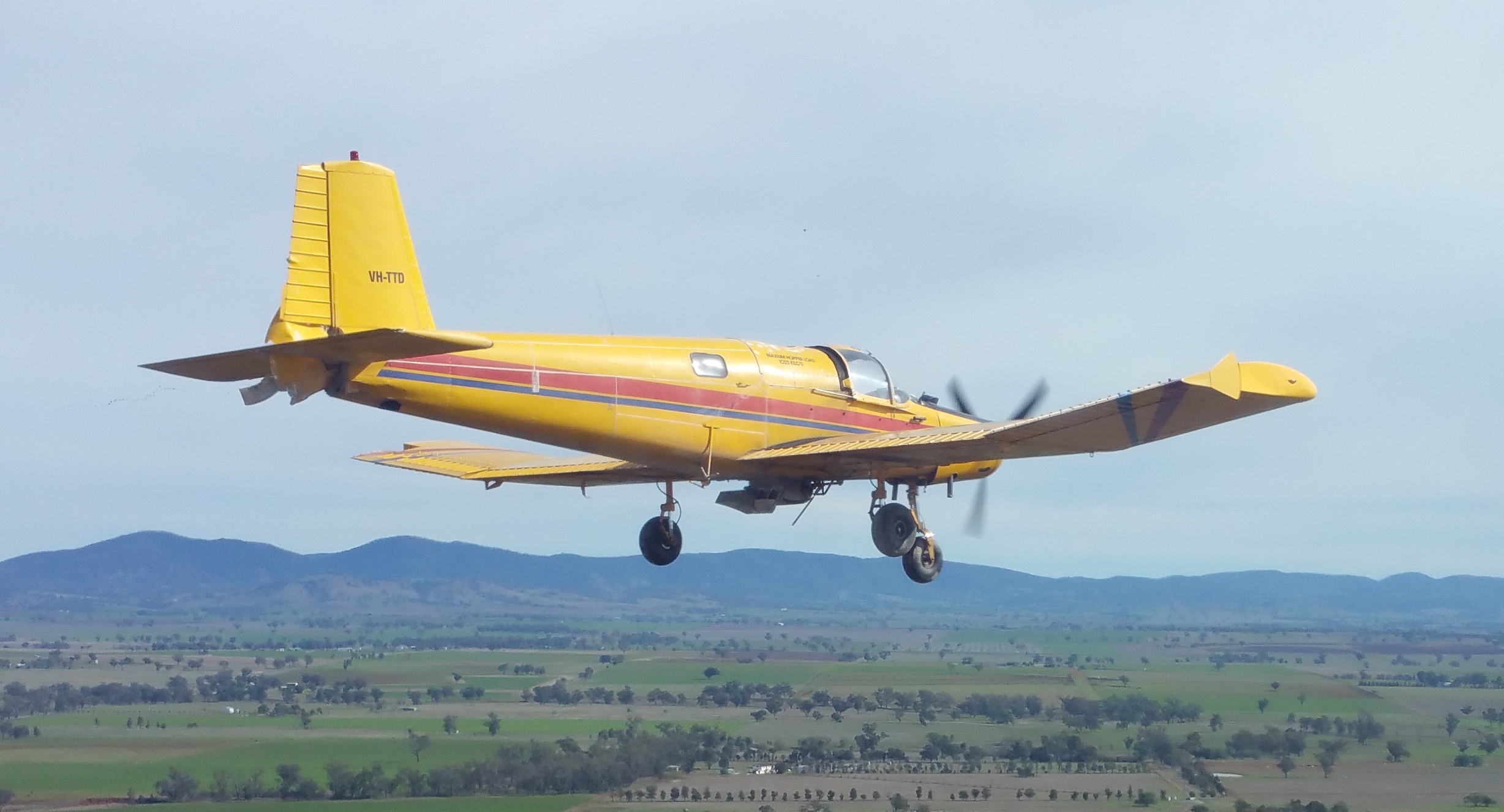
Source: BAE Systems Flight Training Tamworth
Repair organisation findings
The repair organisation that performed the post-incident inspection found damage to the propeller, tailplane and underside of aircraft consistent with impact with the runway and fence during the take-off. A detailed inspection inside the airframe revealed the following:
- The structural frame supporting the lower elevator control cable pulley was pushed up about 10 cm (Figure 2).
- The centre section just aft of the hopper (Figure 3) had about 12 mm of water in it and the drain hole for the centre section was blocked by fertiliser. The repair organisation assessed that the size of the drain hole was inadequate and that a larger hole with a removable bung would be preferable.
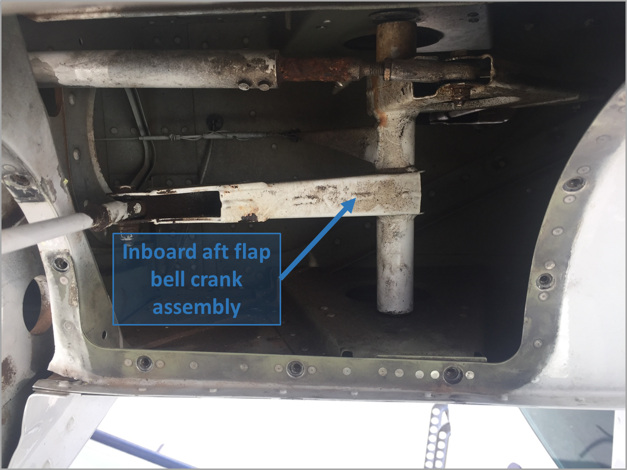
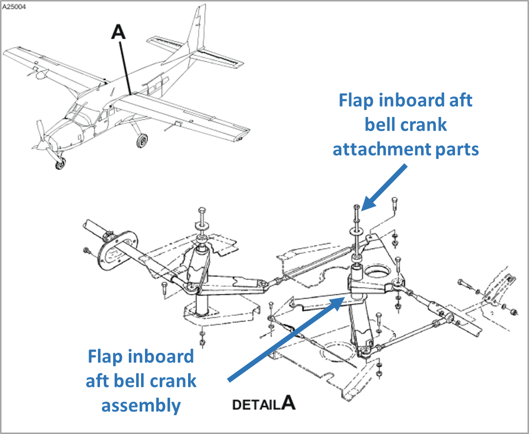
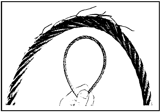
- The flap control cable had failed at the rear flap pulley and the failure appeared to be due to corrosion (Figure 4).
Figure 2: VH-TTD elevator control cable pulley
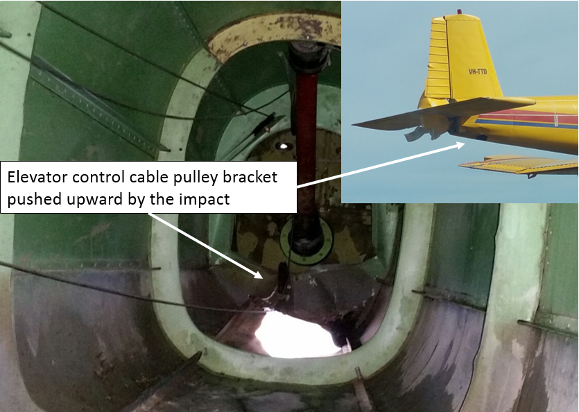
Source: Repair organisation and BAE Systems Flight Training Tamworth annotated by ATSB
Figure 3: VH-TTD centre section
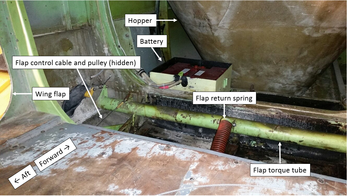
Source: Repair organisation annotated by ATSB
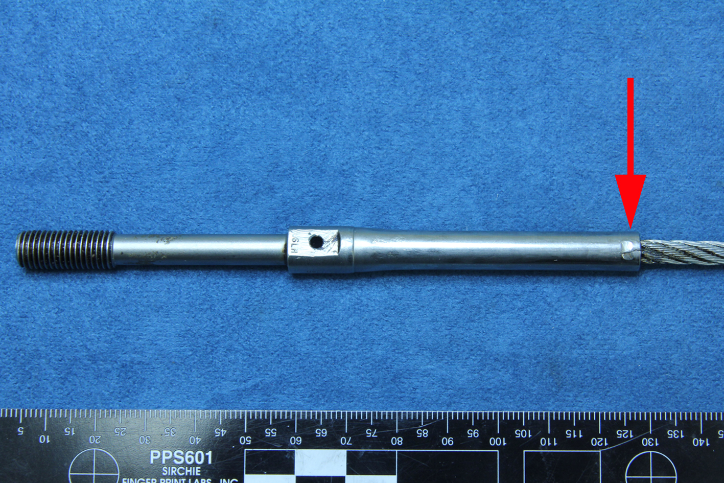
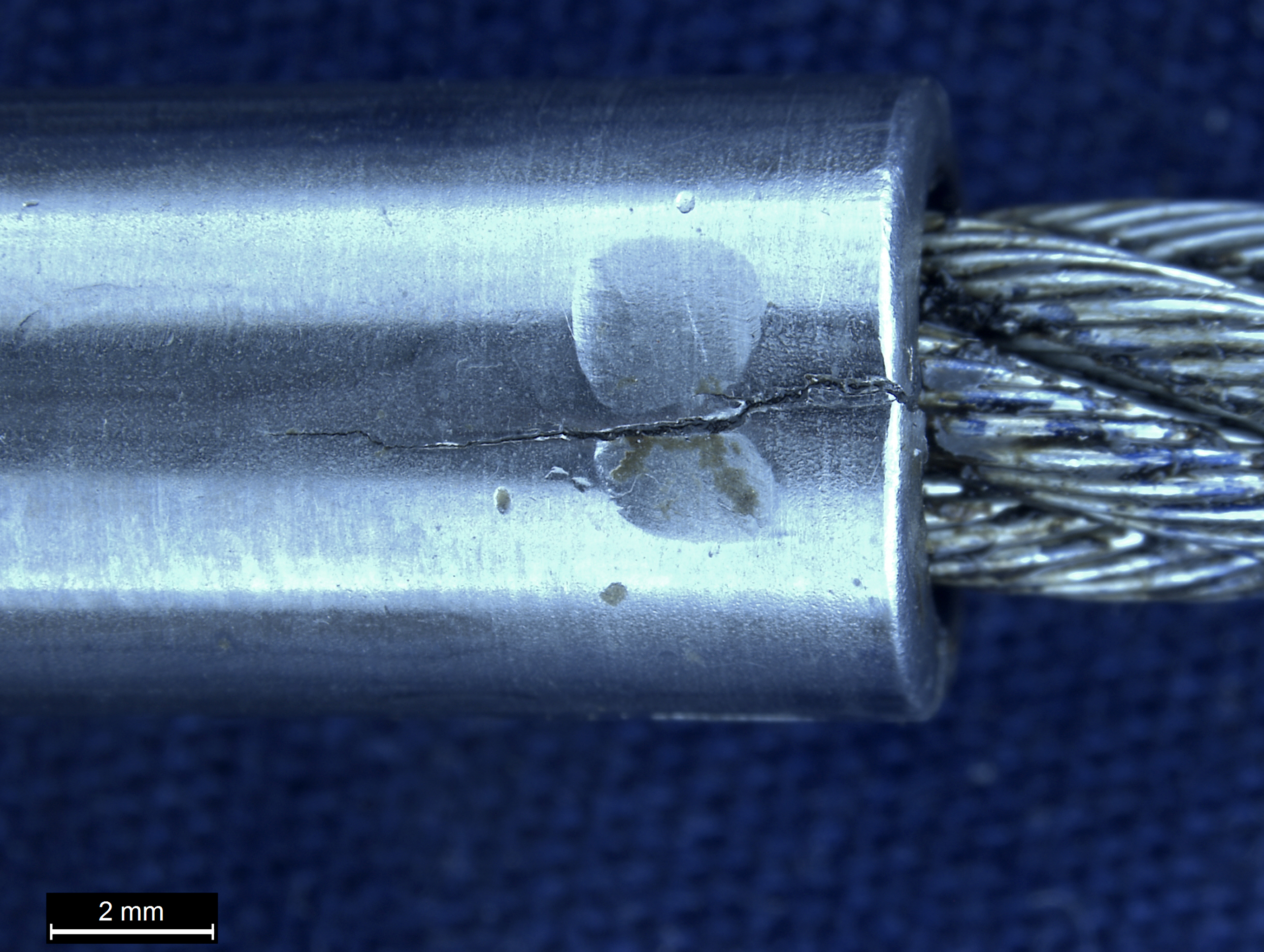
Figure 4: VH-TTD broken flap cable
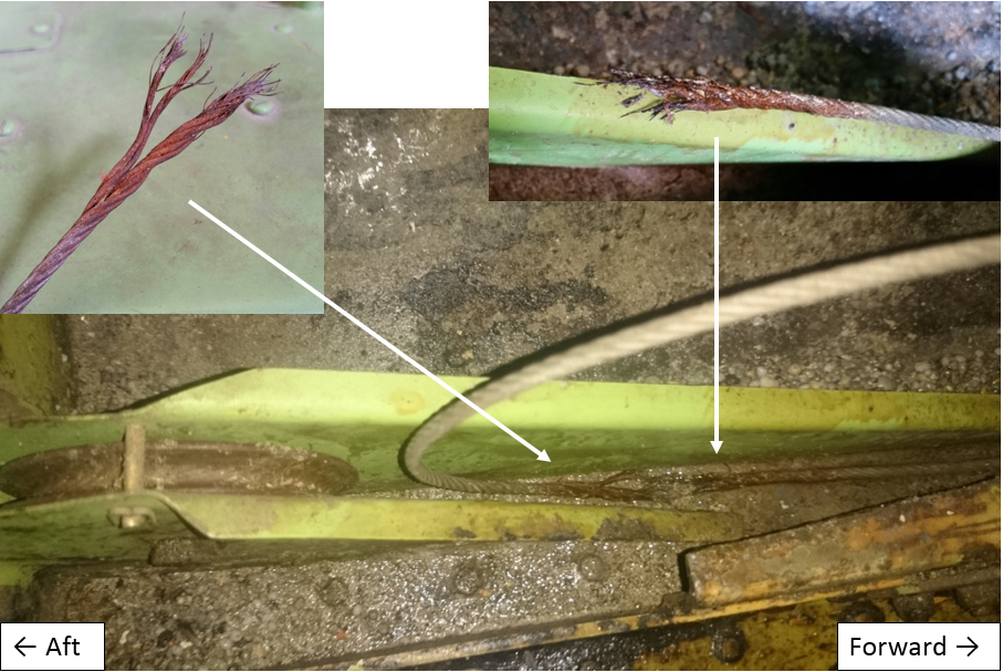
Source: Repair organisation annotated by ATSB
Maintenance schedule
The aircraft system of maintenance used was the Civil Aviation Safety Authority (CASA) Schedule 5 with 100-hourly periodic inspections. CASA Schedule 5 includes the following inspections relevant to this incident:
- Item 3 (j) for the airframe periodic inspection: ‘inspect the control wheels, control columns, rudder pedals, control levers, control system bellcranks, push pull rods, torque tubes and cables.’
- Item 17 for the daily inspection: ‘check that the drain holes are free from obstruction.’[5]
Previous maintenance inspections
The last 100-hourly periodic inspection was certified on 19 May 2016 in accordance with CASA Schedule 5. The previous periodic inspection was on 21 April 2016, and a corrosion inspection was performed on 23 November 2015, which included CASA Airworthiness Directive
. No findings were recorded against the flap control cable for these inspections. During the periodic inspections, the flap cable was inspected by moving a cloth along the cable and no broken strands were detected, and there was no water present in the centre section of the aircraft aft of the hopper. However, the maintenance organisation indicated that they did not remove the flap cable for inspection, nor apply corrosion protection to the flap cable during the inspections.Recommended practices
CASA Airworthiness Bulletin 27-001 issue 7 includes the following recommendation:
…flight control cables should be periodically inspected in accordance with manufacturer’s data and FAA AC 43-13-1B Chapter 7, AIRCRAFT HARDWARE, CONTROL CABLES AND TURNBUCKLES, section 8, paragraph 7.149d. To inspect all surfaces of a cable throughout its entire length for wear and fatigue (broken wires) usually requires that the cable be disconnected and removed...
United States Federal Aviation Administration Advisory Circular 43-13-1B chapter 7, section 8, paragraph 7.149 states that: ‘deterioration, such as corrosion, is not easily seen, therefore, control cables should be removed periodically for a more detailed inspection and any cable with a broken strand in a critical fatigue area[6] must be replaced.’ See Figure 5 below.
- Paragraph 7.149i states that: ‘Areas especially conducive to cable corrosion are battery compartments…etc.; where a concentration of corrosive fumes, vapours, and liquids can accumulate.’
- Paragraph 7.152 states that where control cables pass over pulleys: ‘Provide corrosion protection for these cable sections by lubricating with a light coat of grease or general purpose, low-temperature oil.’
Figure 5: Cable inspection technique
Source: FAA AC 43.13-1B page 7-35
ATSB comment
The ATSB notes that the corrosion present on the flap control cable at the location of the failure takes a considerable amount of time to develop. The corrosion was confined to the working length of the cable that was in contact with the flap control system rear pulley, which is considered to be a critical fatigue area. The failed cable was comprised of woven steel wires plated with zinc or tin. The cable was confirmed to be the correct type for the application.
Over time, in the absence of a suitable lubricant, the plating can wear due to frictional contact with the pulley. This will render the cable susceptible to corrosive attack and elevate the likelihood of a fatigue failure. The flap control cable was not removed during the last periodic inspection, which could have detected the corrosion damage. Nor was grease applied to the working length of the cable, or the rear flap pulley, during the last few inspections to mitigate against the development of corrosion.
Entrapped water, fertiliser and potentially, the previous use of an unsealed lead-acid battery,[7] all contributed to a corrosive environment within the centre section of the aircraft, and corrosion of the flap cable.
Safety action
Whether or not the ATSB identifies safety issues in the course of an investigation, relevant organisations may proactively initiate safety action in order to reduce their safety risk. The ATSB has been advised of the following proactive safety action in response to this occurrence.
Maintenance organisation
As a result of this occurrence, the maintenance organisation has advised the ATSB that they are taking the following safety actions:
Maintenance practices
The FU-24 rear flap control system pulley will be removed during CASA Schedule 5 periodic inspections to facilitate inspection of the flap control cable.
Safety message
This incident highlights the need for maintenance organisations to periodically review the recommended practices published by both the manufacturer and the regulatory authorities. The Schedule 5 system of maintenance details what inspections are required, but does not prescribe how they should be performed. Reference to the relevant industry standard practices can improve the quality of maintenance conducted and ensure an organisation’s practices remain up-to-date with the respective standards, which are periodically updated to incorporate new knowledge.
For further background information on flight control cables and terminals and their failure modes, refer to CASA
(AD/General/87).Aviation Short Investigations Bulletin - Issue 53
Purpose of safety investigationsThe objective of a safety investigation is to enhance transport safety. This is done through:
It is not a function of the ATSB to apportion blame or provide a means for determining liability. At the same time, an investigation report must include factual material of sufficient weight to support the analysis and findings. At all times the ATSB endeavours to balance the use of material that could imply adverse comment with the need to properly explain what happened, and why, in a fair and unbiased manner. The ATSB does not investigate for the purpose of taking administrative, regulatory or criminal action. TerminologyAn explanation of terminology used in ATSB investigation reports is available here. This includes terms such as occurrence, contributing factor, other factor that increased risk, and safety issue. Publishing informationReleased in accordance with section 25 of the Transport Safety Investigation Act 2003 Published by: Australian Transport Safety Bureau © Commonwealth of Australia 2016

Ownership of intellectual property rights in this publication Unless otherwise noted, copyright (and any other intellectual property rights, if any) in this report publication is owned by the Commonwealth of Australia. Creative Commons licence With the exception of the Coat of Arms, ATSB logo, and photos and graphics in which a third party holds copyright, this publication is licensed under a Creative Commons Attribution 3.0 Australia licence. Creative Commons Attribution 3.0 Australia Licence is a standard form licence agreement that allows you to copy, distribute, transmit and adapt this publication provided that you attribute the work. The ATSB’s preference is that you attribute this publication (and any material sourced from it) using the following wording: Source: Australian Transport Safety Bureau Copyright in material obtained from other agencies, private individuals or organisations, belongs to those agencies, individuals or organisations. Where you wish to use their material, you will need to contact them directly. |
__________
- Movable surface forming part of trailing edge of wing, able to hinge downwards to alter wing camber to exert a powerful effect on low speed lift and drag.
- Movable control surface for governing aircraft in pitch.
- The term used to describe motion of an aircraft about its lateral (wingtip-to-wingtip) axis.
- The elevator trim tab is a small hinged portion of the trailing edge of elevator control surface whose setting relative to the elevator surface is set by the pilot and whose effect is to hold the elevator in the desired position for trimmed flight.
- The pilot indicated that they did not believe there were any drain holes in this section of the aircraft.
- A critical fatigue area includes the working length of a cable where the cable runs over, under, or around a pulley.
- VH-TTD was previously fitted with an unsealed battery, which can vent corrosive fumes. A sealed battery was installed at the last periodic inspection.
Occurrence summary
| Investigation number | AO-2016-067 |
|---|---|
| Occurrence date | 26/06/2016 |
| Location | 50 km ESE of Tamworth Airport |
| State | New South Wales |
| Report release date | 14/10/2016 |
| Report status | Final |
| Investigation level | Short |
| Investigation type | Occurrence Investigation |
| Investigation status | Completed |
| Mode of transport | Aviation |
| Aviation occurrence category | Flight control systems |
| Occurrence class | Serious Incident |
| Highest injury level | None |
Aircraft details
| Manufacturer | Airparts NZ Ltd |
|---|---|
| Model | FU-24-950 |
| Registration | VH-TTD |
| Serial number | 186 |
| Sector | Piston |
| Operation type | Aerial Work |
| Damage | Minor |