Descent below minimum descent altitude involving a Boeing 737-300, VH-NLK, Kosrae International Airport, Federated States of Micronesia, on 12 June 2015
Final report
What happened
On 12 June 2015, the crew of a Boeing B737-300, registered VH-NLK, were conducting a non-directional beacon/distance measuring equipment (NDB/DME) approach into Kosrae Airport in the Federated States of Micronesia. The flight was the inaugural regular public transport (RPT) flight for Nauru Airlines into Kosrae. During the approach, at night and in instrument meteorological conditions, the aircraft descended below the minimum descent altitude and three enhanced ground proximity warning system (EGPWS) ‘too low terrain’ alerts were triggered. A go-around was performed prior to the aircraft reaching the missed approach point. During the go-around, the airspeed decayed and required the pilot to use full thrust. The flight crew identified and corrected the barometric pressure setting and the subsequent approach and landing into Kosrae were uneventful.
What the ATSB found
The flight crew did not complete the approach checklist before commencing the non-precision NDB approach into Kosrae, resulting in the barometric pressure setting on the altimeters not being set to the local barometric pressure. This resulted in the aircraft’s altitude being lower than what the pressure altimeter was indicating to the pilots. The aircraft descended below the EGPWS terrain clearance floor profile for the Kosrae runway, resulting in three separate EGPWS alerts.
Terrain clearance assurance was eroded further after receiving the first two EGPWS alerts by the flight crew not correcting the flight profile. The crew's belief that the EGPWS alerts were due to a decreased navigational performance and not terrain proximity led to the crew’s decision to inhibit the first EGPWS alert and not correct the flight path.
The flight crew initiated a missed approach when they lost visual contact with the runway. The captain was experiencing fatigue and the flight crew had an increased workload and stress due to the inaugural RPT flight into Kosrae at night in rapidly deteriorating weather. As a result, the crew’s decision making and task execution on the missed approach were affected, and the aircraft state, airspeed and attitude were not effectively monitored by either crew member.
The ATSB also found that there were established risk factors associated with Kosrae at the time the operator commenced regular public transport operations into Kosrae. The only instrument approach available for use was an offset procedure based on a non-precision navigation aid. The risk associated with this type of approach was amplified due to the need to use a 'dive and drive' style technique instead of a stable approach path, and that it required low level circling manoeuvring from the instrument approach to align the aircraft with the runway. Furthermore, there was very high terrain in close proximity to the runway and the airport did not have a manned air traffic control tower.
What's been done as a result
Following this occurrence, the operator has reviewed and changed procedures relating to:
- increased time for flight crew on non-standard/non-routine activities during their cyclic training program
- reviewed and included control column checklists, which includes the descent and approach checklist, with tactile indicators
- included two-engine go-arounds in simulator sessions
- reviewed and improved awareness of QNH setting procedures and human factors aspects of briefings and line checks.
Safety message
This occurrence highlights the importance of flight crews declaring any instances of acute fatigue and stress-inducing circumstances that may have an impact on their flying performance. Operators also need to remind flight crew of the importance of their decisions with regards to their fitness to fly. For flight crews, the importance of completing approach checklists and monitoring the approach at safety critical times is emphasised. For operators, the occurrence highlights the importance of incorporating dual-engine go-arounds into simulator training sessions.
Findings
From the evidence available, the following findings are made with respect to the Enhanced Ground Proximity Warning System (EGPWS) alerts involving a Boeing 737-300, VH-NLK, at Kosrae International Airport, Federated States of Micronesia, on 12 June 2015. These findings should not be read as apportioning blame or liability to any particular organisation or individual.
Safety issues, or system problems, are highlighted in bold to emphasise their importance. A safety issue is an event or condition that increases safety risk and (a) can reasonably be regarded as having the potential to adversely affect the safety of future operations, and (b) is a characteristic of an organisation or a system, rather than a characteristic of a specific individual, or characteristic of an operating environment at a specific point in time.
Contributing factors
- The flight crew did not complete the approach checklist before commencing the non-precision NDB approach into Kosrae. As a result, the altimeters' barometric pressure settings remained at the standard setting of 1013 hPa instead of being set to the reported local barometric pressure of 1007 hPa. The flight crew descended the aircraft to the minimum descent altitude of 500 ft as indicated by the altimeters, however, due to the barometric pressure setting not being reset, the aircraft descended to a height significantly below 500 ft.
- The crew descended the aircraft in IMC and at night below the approach profile for the Kosrae runway, resulting in EGPWS alerts. Terrain clearance assurance was eroded further by the flight crew not correcting the flight profile until the flight crew lost visual contact with the runway.
- The flight crew's belief that the EGPWS warnings were due to a decreased navigational performance and not terrain proximity led to their decision to inhibit the first EGPWS warning and not correct the flight path.
- Due to the captain’s fatigue and the increased workload and stress associated with the inaugural regular public transport flight into Kosrae at night in rapidly deteriorating weather, the crew’s decision making and task execution on the missed approach were affected.
Other factors that increased risk
- The crew’s recurrent training had not included B737-300 full thrust go-around simulations.
- The operator commenced regular public transport operations into Kosrae with the only instrument approach available for use being an offset procedure based on a non-precision navigation aid. The risk associated with this type of approach was amplified due to the need to use a 'dive and drive' style technique instead of a stable approach path, and that it required low level circling manoeuvring from the instrument approach to align the aircraft with the runway. Furthermore, there was very high terrain in close proximity to the runway and the airport did not have a manned air traffic control tower. For this occurrence, the risk was further elevated as a result of the approach being conducted at night-time in poor weather conditions. [Safety issue]
Sources and submissions
Sources of information
The sources of information during the investigation included the:
- flight crew and operator of VH-NLK
- aircraft enhanced ground positioning warning system (EGPWS)
- EGPWS manufacturer
- The US Federal Aviation Administration
- Airservices Australia
- Civil Aviation Safety Authority.
References
Battelle Memorial Institute. (1998). An Overview of the scientific literature concerning fatigue, sleep, and the circadian cycle, Report prepared for the Office of the Chief Scientific and Technical Advisor for Human Factors, US Federal Aviation Administration.
Bureau d’Enquêtes et d’Analyses pour la sécurité de l’aviation civile (BEA). (2013). Study on aeroplane state awareness during go-around. Available from www.bea.aero/etudes/asaga/asaga.php
Dawson, D., & McCulloch, K., (2005). ‘Managing fatigue: It’s about sleep’, Sleep Medicine Reviews, vol. 9, pp. 365-380.
Dismukes, K. (2006). Concurrent task management and prospective memory: pilot error as a model for vulnerability of experts. In Proceedings of the Human Factors and Ergonomics Society 50th Annual Meeting – 2006, pp. 909-913.
Dismukes, R.K. and Berman, B. (2010). Checklists and monitoring in the cockpit: Why crucial defences sometime fail. National Aeronautics and Space Administration Technical Memorandum NASA/TM-2010-216396. Ames Research Centre: Moffett Field, US.
Flight Safety Foundation (FSF) (1998). Flight Safety Digest, November 1998—February 1999: “Killers in Aviation”. Available from flightsafety.org
Gaillard, A.W.K. (2001). Stress, workload and fatigue as three biobehavioural states: A general overview. In P.A. Hancock, & P.A. Desmond (Eds.), Stress, workload, and fatigue. Mahwah, NJ: L. Erlbaum.
Gawron, V.J., French, J., & Funke, D. (2001). An overview of fatigue. In P.A. Hancock, & P.A. Desmond (Eds.), Stress, workload, and fatigue. Mahwah, NJ: L. Erlbaum.
Orlady, H.W., & Orlady, L.M. (1999). Human factors in multi-crew flight operations. Ashgate: Aldershot, UK p.203.
Thomas, M.J.W., & Ferguson, S.A., (2010). Prior sleep, prior wake, and crew performance during normal flight operations, Aviation, Space, and Environmental Medicine, vol. 81, pp. 665-670.
Staal, M.A. (2004). Stress, cognition and human performance: A literature review and conceptual framework. National Aeronautics and Space Administration Technical Memorandum NASA/TM–2004–212824. Ames Research Centre: Moffett Field, US.
Williamson, A., Lombardi, D.A., Folkard, S., Stutts, J., Courtney, T.K., & Connor, J.L., (2011). The link between fatigue and safety, Accident Analysis and Prevention, vol. 43, pp. 498-515.
Submissions
Under Part 4, Division 2 (Investigation Reports), Section 26 of the Transport Safety Investigation Act 2003 (the Act), the Australian Transport Safety Bureau (ATSB) may provide a draft report, on a confidential basis, to any person whom the ATSB considers appropriate. Section 26 (1) (a) of the Act allows a person receiving a draft report to make submissions to the ATSB about the draft report.
A draft of this report was provided to the flight crew, Nauru Airlines, the Federated States of Micronesia, and the Civil Aviation Safety Authority.
Submissions were received from the Civil Aviation Safety Authority and Nauru Airlines. The submissions were reviewed and where considered appropriate, the text of the report was amended accordingly.
Safety analysis
Introduction
While positioning the aircraft to commence the non-directional beacon/distance measuring equipment (NDB/DME) approach into Kosrae airport, Federated States of Micronesia, the approach checklist was not completed and so the altimeters were not set to the local barometric pressure. This resulted in the aircraft’s actual altitude being180 ft lower than the pressure altimeter’s reading. Three enhanced global positioning warning system (EGPWS) ‘Too Low Terrain’ alerts were triggered due to the aircraft's altitude being below the minimum terrain clearance.
The flight crew believed that the EGPWS alerts were due to decreased navigational performance and not terrain proximity. This led to the flight crew’s decision to inhibit the first EGPWS alert and not correct the flight path prior to their deciding to perform a go-around manoeuvre.
The captain stated that he was fatigued and the crew stated that they were experiencing increased workload. This appears to be due to the flight being the inaugural regular public transport flight into Kosrae, conducted at night in rapidly deteriorating weather. Fatigue, workload and stress appear to have affected the crew’s decision making and task execution on the missed approach.
This analysis will examine the type of approach procedure available to the flight crew for Kosrae, the operator’s operational procedures, the conduct of the go-around manoeuvre and the effects of fatigue, workload and stress on the occurrence.
Level of risk associated with the approach
The Flight Safety Foundation’s Approach and Landing Accident Reduction task force provided a number of focal points that were present in the occurrence approach into Kosrae, which in turn indicated an elevated level of risk associated with that approach.
Risk associated with the localised high terrain was mitigated by the aircraft having EGPWS based warning systems fitted. Risk factors of a night-time approach into an airport without a manned tower were the result of delays encountered over the previous sectors, issues that should be considered by the operator in a risk analysis for operations into Kosrae before commencing these operations. A further risk factor necessary for consideration prior to commencing operations into Kosrae was that there were only two types of instrument approaches: runway aligned GPS-based approaches, and the offset non-precision approach. As the occurrence aircraft was not fitted with equipment required for GPS based approaches, and the operator not approved to conduct them, the only option for operations into Kosrae was to conduct a non-precision approach. This elevated the risk associated with the approach, and that risk was further amplified by:
- the approach necessitating a ‘dive and drive’ profile due to:
- the offset of the final approach course from the runway heading
- the location and height of the missed approach point, which was well below a normal 3 approach profile.
- the need to conduct low level manoeuvring from the missed approach point to enable the aircraft to align with the runway.
The aircraft’s navigation system also represented a significant risk factor in the conduct of this approach. While the operator’s procedure required the use of raw navigational data for the approach, the use of an NDB as a primary approach aid is subject to several effects that can result in error, including the night effect, thunderstorm activity and localised high terrain, which were all potential sources of navigation error in this occurrence.
Further, due to the limited number of navigation aids available on the occurrence sector, the navigation system was dependent on inertial reference for position data. This will often result in the ‘map shift’ error being presented to the pilots, where the pilot’s navigation displays are significantly ‘shifted’ from the actual real-world position of the displayed data, and can contribute flight crew error. With respect to the occurrence flight, the flight crew incorrectly believed that the initial EGPWS alerts were the result of a ‘map shift’ error; however, a comparison between the aircraft’s quick access recorder data and the EGPWS GPS data identified a map shift error of about 1 NM seawards of where the aircraft’s actual position was.
The flight crew’s conduct of a briefing for the approach, and decision to perform a go-around when visual contact with the runway was lost, mitigated the risks to some extent.
Approach checklist
Prospective memory can be defined as the intention to perform an action in the future, coupled with a delay between recognising the need for action and the opportunity to perform it. A distinguishing feature of prospective memory is the need for an individual to remember that they need to remember something. Researchers (Dismukes, 2006) have identified that prospective memory issues may result in a failure to return to a task or procedure that has been interrupted, even when the task or procedure is habitual.
The crew had briefed the new transition level at top of descent and had briefly discussed the need to conduct the approach checklist on passing through the transition level when they were descending through FL 130 (the usual transition level). The crew had put a plan in place to complete the checklist. However, as they were flying over the non-directional beacon at FL 050 and were looking at the runway in preparation for the commencement of the approach, workload began to rise and they forgot to return to the approach checklist and complete it, as per a prospective memory error. Thus, as the aircraft descended through the transition level, the altimeters were not set to the local barometric pressure from the standard pressure setting of 1013 hPa and, as a result were over-reading the aircraft’s altitude by 180 ft. The aircraft’s actual height was, on average, 120 ft lower than the aircraft’s indicated altitude.
EGPWS warnings and crew response
The EGPWS issued a series of Terrain Clearance Floor (TCF) alerts during the NDB/DME approach into Kosrae. The EGPWS recorded data for a period around the EGPWS events. At the beginning of recording, the aircraft was 5.1 NM from the runway, with landing gear down, at a radio altimeter height of 663 feet and a vertical speed of -1,011 fpm. At approximately 19, 25 and 61 seconds after the commencement of the EGPWS recording, the EGPWS issued a ‘TOO LOW TERRAIN’ alert due to the aircraft’s penetration of the TCF envelope.
The EGPWS also recorded a ‘terrain inhibit’ parameter which corresponded to the pilot selection of the terrain inhibit feature. In the recorded data, the terrain inhibit was activated for two seconds, occurring four seconds after the beginning of the first TCF alert.
The flight crew stated that they heard the EGPWS warning prior to their reaching the missed approach point (MAP) and that they had the runway lights in sight although the visibility was fluctuating, and decided to keep going because they had a visual reference for the runway. Furthermore, the flight crew thought the warnings were due to map shift. Therefore, the flight crew believed the warnings were false and inhibited the first warning due to this belief.
The operator’s operations manual stated that, in instrument meteorological conditions (IMC), all EGPWS alerts were to be treated as genuine and flight crew must take rectification or avoidance action immediately. The operator’s flight crew operations manual stated that if positive visual verification was made that no obstacle or terrain hazard existed when flying under daylight VMC conditions prior to a terrain or obstacle warning, the alert could be regarded as cautionary and the approach continued.
The investigation found that the approach was being conducted at night in intermittent visual conditions prior to the aircraft going into IMC conditions just prior to the MAP. In these conditions, the EGPWS warnings should have been treated as genuine and action taken immediately rather than the crew inhibiting the alert.
Fatigue, workload and stress
The captain’s mother had become ill and her health had severely degraded by the time the captain arrived in Nauru from Brisbane. The captain stayed with her at the hospital for as long as possible before returning to his hotel where he had a disrupted night’s sleep of less than 6 hours. At the time of the EGPWS warnings, the captain had been awake for about thirteen hours and reported feeling fatigued.
The crew reported that their workload increased following the EGPWS alerts due to the deteriorating weather and distraction of the Kosrae flight information service (FIS) providing wind velocity change and visibility updates. The first officer stated that the FIS updates interrupted the crew’s working through checklists, as they needed to listen and respond. The effect of the increased workload would have been exacerbated by the stress of flying the operator’s inaugural RPT flight into Kosrae with Nauruan dignitaries on board.
For the captain, the workload would have been further exacerbated by the stress of his mother’s illness and the fatigue of a disrupted night’s sleep. The captain stated that in hindsight, he should have removed himself from the flight but didn’t want to as he was only one of two Nauruan captains employed by the operator and it was his turn to fly an important flight. He did not inform the operator of his mother’s illness.
On the decision to go-around, the captain pressed the takeoff/go-around button only once instead of twice, which resulted in a reduced thrust rather than a full power go-around. The aircraft was pitched up initially to 15° but was then pitched back down to increase the decaying airspeed. Soon after, the aircraft was at its lowest height of 200 ft by the radio altimeter. Given the increased workload of the crew, and the effects of stress and fatigue on the captain, the aircraft state, airspeed and attitude was not effectively monitored by either crew member following the go-around decision. Therefore, the execution of the go-around task and its attendant decision making was not performed effectively.
The go-around manoeuvre and recurrent training
The survey on the conduct of the go-around manoeuvre by the Bureau d’Enquêtes et d’Analyses (BEA, 2013) identified that it was common for the pilot flying to experience aircraft handling difficulties during the initial phase of the all-engine go-around manoeuvre, and that there was a general lack of training for the all-engine go-around manoeuvre.
With respect to the incident pilot’s handling issues during the go-around, these may have been affected by fatigue, workload and stress. However, it is also likely that these handling issues were contributed to by the limited training for the all-engine full-thrust go-around. The development of a recurrent training syllabus is a complex process and, as well as meeting specific regulatory requirements, involves operators making decisions about which of many important tasks and situations need to be included in each session. Go-arounds with one engine inoperative are typically conducted in every recurrent training session, and there has been increasing recognition that regularly practicing all-engine go-arounds is also important (BEA, 2013). Although the procedural steps are fundamentally the same, the increase in energy and time pressure associated with an all-engine go-around provides different challenges.
There are many permutations of the go-around task that need to be covered in recurrent training. A lesson from this occurrence and many similar occurrences is that flight crews should be regularly exposed to the time pressure and challenge of conducting full thrust go-arounds.
At the time of the occurrence, the operator did not include full-thrust go-arounds as part of their simulator-based recurrent training for their pilots. Although the inclusion of more go-around training including these aspects will reduce the overall risk associated with go-arounds, it is difficult to conclude that they would necessarily have reduced the likelihood of this occurrence.
The occurrence
On 12 June 2015, a Nauru Airlines[1] Boeing 737-300 aircraft, registered VH-NLK, operated a scheduled passenger flight originating in the Republic of Nauru and transiting Tarawa, Republic of Kiribati, and Marshall Islands Airport, Majuro atoll, Republic of the Marshall Islands, to Kosrae Airport and finally Pohnpei Airport, both in the Federated States of Micronesia (FSM). This was the operator’s inaugural scheduled regular public transport service to Kosrae and Pohnpei. Travelling on-board were the Nauruan President, the Nauruan Minister of Aviation, and the Chairman of the Board of Directors of Nauru Air Corporation. In the six weeks preceding this flight, the operator had flown three charter flights to the FSM airports. The captain also stated that he had flown a couple of charter flights (during the day) into Kosrae before this inaugural scheduled service.
The flight was originally scheduled to leave Nauru at 0230 Coordinated Universal Time (UTC) (1430 Nauru Time).[2] However, a technical issue with the original aircraft led to a change to VH‑NLK. This resulted in the aircraft departing 60 minutes late. The flight crew, comprising of a captain and first officer, originated in Nauru having been positioned there from their base in Brisbane, Queensland, the day before.
The sector from the Marshall Islands to Kosrae was delayed a further 17 minutes due to ground handling issues. The flight departed after last light at 0740 and the planned flight time was 1 hour 19 minutes. The approach and landing at Kosrae was at night.
For this sector, the captain was the pilot flying, and the first officer was the pilot monitoring.[3] During the climb to the planned cruising altitude of flight level (FL)[4] 360, in accordance with standard procedures, the flight crew selected the standard atmospheric pressure of 1013 hPa on the altimeters.
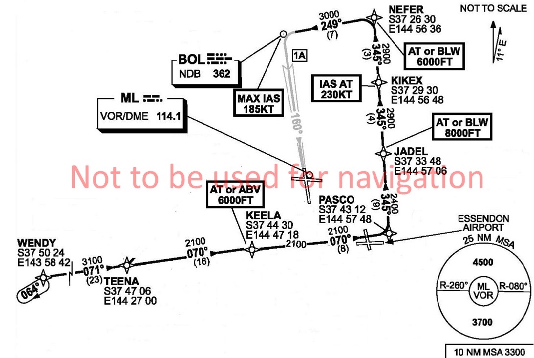
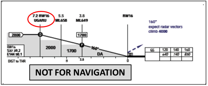
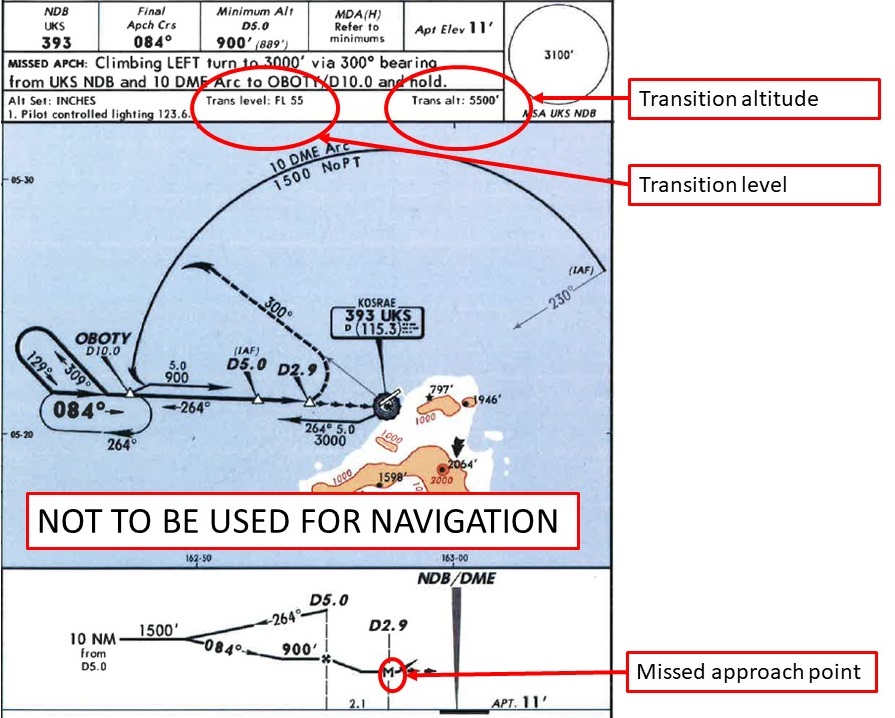
The flight crew stated that, prior to commencing the descent for Kosrae, they obtained the weather and the local QNH.[5] The weather had deteriorated from that forecast (see section titled Meteorological information). The flight crew also stated that, during the descent and approach, the local flight information service radio operator[6] provided a considerable number of weather updates on the local airport conditions at Kosrae. Visibility was around 3 NM, rain showers were in the area with low cloud and wind ‘pretty much straight down the strip for (runway) 05’. The captain, as pilot flying, conducted the briefing for the non-directional beacon (NDB)[7]/distance measuring equipment (DME)[8] approach to runway 05 (Figure 1). The captain stated that, at this time, they had made special mention of the unusually low transition level[9] of FL 55. The captain stated that at most airports they operated into, the transition level was between FL 110 and FL 130.
The crew then completed the descent checklist. They had decided that, based on the expected weather conditions, they would make two approach attempts, and if they could not land, would divert to Nauru Airport, the nominated alternate airport. Prior to descending below the transition level, the crew did not complete the approach checklist, which consisted of one item: set the altimeters to the local QNH and crosscheck them. Leaving the altimeters’ subscale set to the standard atmospheric pressure setting of 1013 hPa, and not setting the subscale to the local barometric pressure of 1007 hPa, resulted in the indicated altitude over-reading, such that when the altimeter indicated 500 ft, the aircraft’s actual altitude was about 320 ft above the mean sea level.
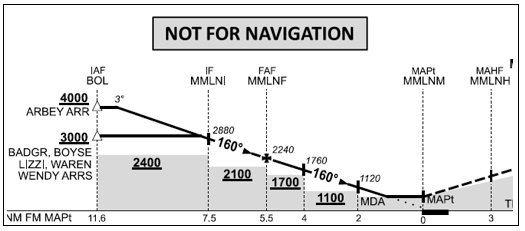
Figure 1: Kosrae NDB/DME-A approach chart with the transition altitude and level, and missed approach point highlighted
At about 0856, the aircraft passed overhead the NDB at 5,000 ft, and continued the descent, tracking outbound on a heading of 300°, to about 10 NM from the NDB (10 DME). The flight crew were controlling the aircraft through the auto-flight systems, with an autopilot and the autothrottle engaged. At this point, the crew turned the aircraft left, and at 0901, the aircraft intercepted the inbound track to the NDB at about 1,800 ft. The crew selected the landing gear down at 1,500 ft, and flap 15 at 1,250 ft.
The crew stated that they established visual contact with the runway as the aircraft passed through 900 ft indicated altitude, about 5 NM from the DME. At about 740 ft indicated altitude, the crew selected flap 25. The crew elected to delay selection of the nominated landing flap of 40 degrees until they made positive visual contact with the runway. They did not subsequently select flap 40 on that approach.
As the aircraft descended to the minimum descent altitude for the approach of 500 ft, the captain selected the altitude hold (ALT HOLD) mode to level the aircraft at 500 ft indicated altitude. At 0903:13, an Enhanced Ground Proximity Warning System (EGPWS) Terrain Clearance Floor (TCF) alert (see section titled EGPWS alerts) sounded, and lasted for 5 seconds (Figure 2). The aircraft was over water, at 368 ft radio altitude.[10] The crew reported that they were in visual meteorological conditions (VMC) at night, with the runway lights in sight. The crew stated that, at the time, they believed the EGPWS alert was due to a ‘map shift’ in the aircraft’s navigation position (see section titled The navigation function of the flight management system). The flight crew selected ‘terrain inhibit’, which cancelled the current EGPWS TCF alert. The crew were not aware that the EGPWS had its own internal GPS.
At 0903:19, the aircraft was at 4.31 DME, 480 ft indicated altitude and 340 ft radio altitude, and descending at about 313 fpm, when the EGPWS TCF alert again sounded, and lasted for 12 seconds. The aircraft maintained 480 ft indicated altitude for about 12 seconds, before descending again.
Figure 2: Approach profile annotated with indicated and radio altimeter readings highlighting the difference between the displayed and actual altitudes plus the three EGPWS Terrain Clearance Floor alerts and the Terrain Inhibit alert cancellation activation
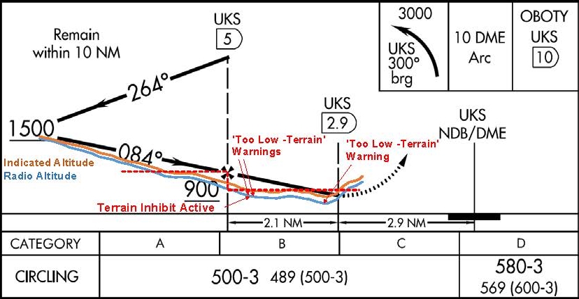
Source: FAA and ATSB
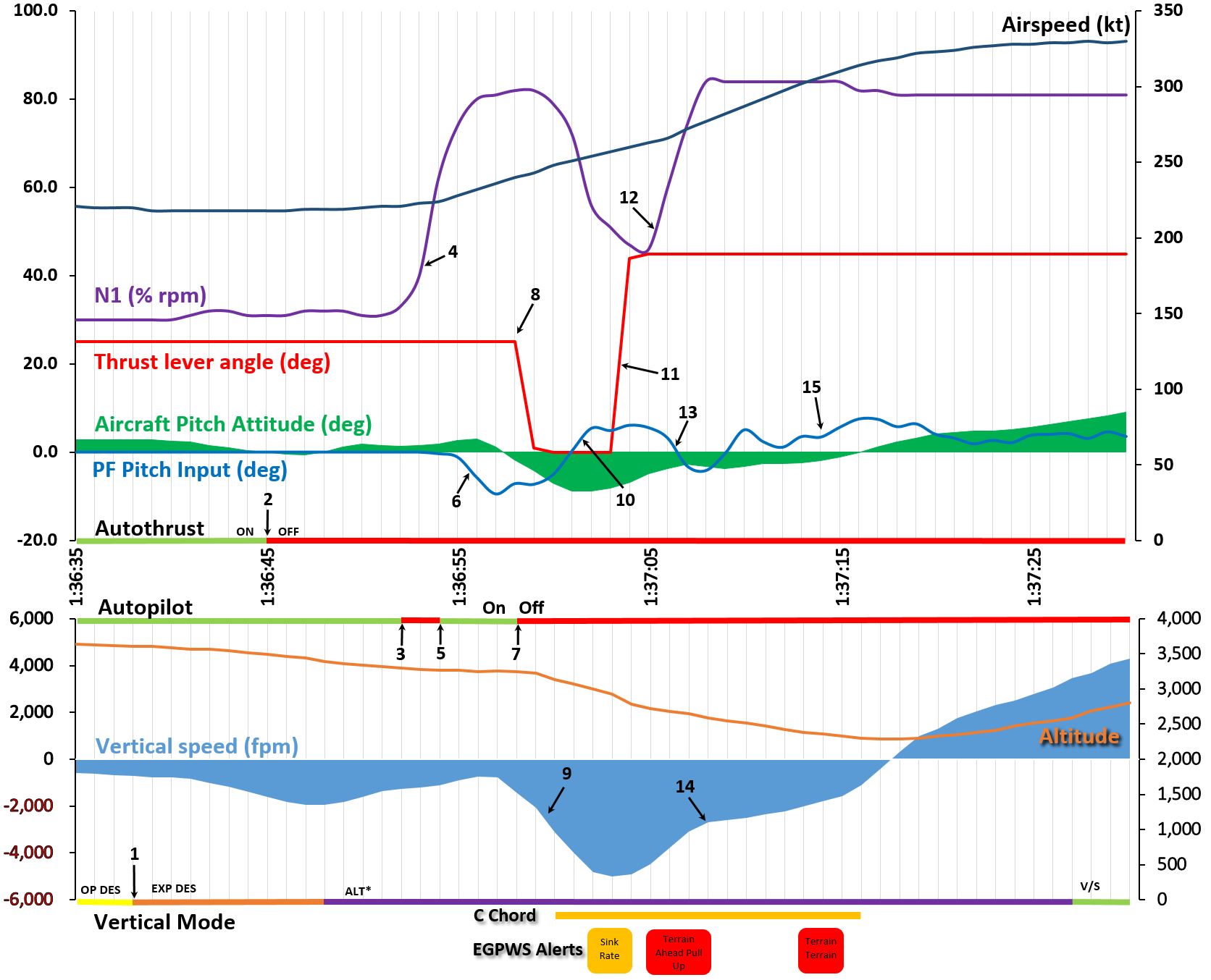
The crew reported losing visual reference with the runway when the aircraft was about 3 NM from the DME. In response to losing visual reference, the captain disconnected the autopilot and autothrottle and pressed the take-off/go-around (TOGA) switches on the thrust levers. At this time the recorded aircraft pitch angle was 9.5°. The flight data recorder data showed that TOGA was selected at 0903:47, at 448 ft indicated altitude, or 304 ft radio altitude (see Figure 3), and the aircraft was about 3.5 NM from the DME. At this time, the aircraft’s computed airspeed reduced to 129 kt.
The captain stated that he pressed the TOGA switches on the thrust levers once. In the Flight Director engaged go-around mode, one TOGA switch press results in a reduced thrust autothrottle setting, and two presses of the TOGA switch advances the autothrottle to full go-around thrust (see section titled Autothrottle go-around modes). The crew stated that the aircraft pitch angle was initially raised to 15°, however, the captain observed the airspeed decay and pitched the aircraft down to increase the airspeed. The first officer stated he called ‘sink rate’ twice. The captain then realised and rectified the situation, depressing the TOGA switch a second time commanding full go-around thrust.
At 0903:53, the aircraft was at 3.3 DME, and the third EGPWS TCF alert sounded, which lasted for 10 seconds. The aircraft was then at 384 ft indicated altitude, or 244 ft radio altitude, and descended 5 seconds later to its lowest radio altitude of 200 ft before climbing.
At 0904:04, the flaps were retracted to 15° and the aircraft reached its maximum pitch up angle of 16°. Two seconds later, the flaps were retracted to 10°. From the time the captain set the thrust to TOGA until the aircraft was stabilised on the missed approach path (at about 0905), the recorded aircraft pitch angle varied from -0.35° to +16°.
Figure 3: Selected flight data recorder data plot
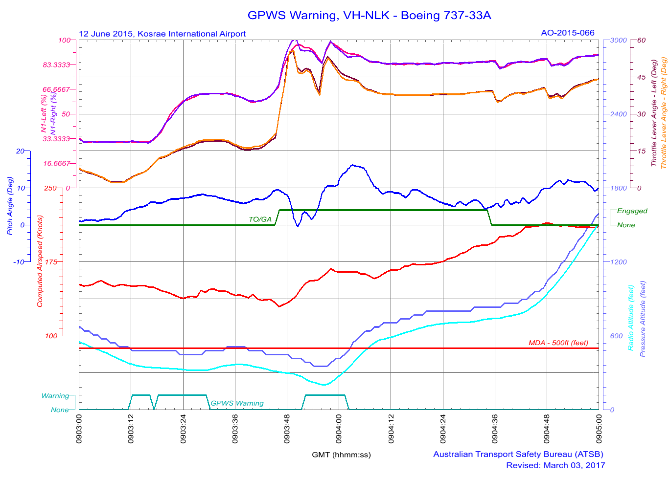
Source: ATSB
When the aircraft was established on the missed approach heading, the captain continued a climb to 4,000 ft. After stabilising the aircraft in the missed approach, the crew identified that the altimeters were still set to 1013 hPa and corrected them to the local area QNH. After repositioning overhead, the NDB at 4,000 ft, the crew then conducted a second approach and the aircraft landed at Kosrae without further incident.
__________
- The operator’s Air Operator’s Certificate was issued to Nauru Air Corporation, trading as Nauru Airlines (also known as Our Airline). The airline is the flag carrier airline of the Republic of Nauru. Since 1996, the airline has been operating under Australian civil aviation regulations with an Australian Air Operators Certificate.
- Coordinated Universal Time is the time zone used for civil aviation. Nauru local time was UTC + 12 hours and Kosrae local time was UTC + 11 hours. UTC will be used for the remainder of this report unless otherwise stated.
- Pilot flying and pilot monitoring are procedurally assigned roles with specifically assigned duties at specific stages of a flight. The PF does most of the flying, except in defined circumstances; such as planning for descent, approach and landing. The PM carries out support duties and monitors the PF’s actions and aircraft flight path.
- Flight level: at altitudes above 10,000 ft in Australia and 5,000 ft in FSM, an aircraft’s height above mean sea level is referred to as a flight level (FL). FL 360 equates to 36,000 ft.
- The altimeter barometric pressure subscale setting used to indicate the height above mean sea level.
- Kosrae airport did not have an air traffic control tower. The airport operated a common traffic advisory frequency, which included a flight information type service that was located at the airport.
- A non-directional beacon is an automatic direction-finding radio transmitter at a known location, used as a navigational aid.
- Distance measuring equipment is a transponder-based radio navigation technology that measures slant range distance, or the distance between two points not at the same level – for example, the distance from an aircraft at altitude to a radar antenna.
- Flight above the transition layer is flown at an altimeter setting of 1013 hPa, and flight below transition level is flown by reference to the local QNH.
- Radio altitude is measured by the radio altimeter, an airborne electronic device capable of measuring the height of the aircraft above terrain immediately below the aircraft.
Context
Flight crew information
The captain
The captain held an Air Transport Pilot (Aeroplane) Licence, a multi-engine command instrument rating and a Class 1 Aviation Medical Certificate. The captain had a total of 16,600 hours of aeronautical experience, of which 16,100 hours were on the Boeing 737.
The captain’s last instrument rating had been completed on 14 January 2015 and the last flight review line check completed on 14 February 2015.
The captain reported sleeping well on the nights of 9 and 10 June 2015, obtaining 9.5 and 7 hours on the respective nights. On arriving at Nauru (11 June), he discovered that his mother was very ill. The night prior to the Kosrae duty, he had spent a significant amount of time at the hospital with his mother. The captain stated that he tried to get a few hours decent sleep prior to going to work, achieving five to six hours sleep between 0100 and 0700 local.
In interview, the captain stated that he had not informed the company of the situation with his mother. Some of his colleagues knew that his mother was sick, but not the extent of her illness. The captain stated that he believed it might have led to fatigue because he did not have a good sleep the night prior.
The captain stated that, in hindsight, it would have been better to remove himself from duty, but stated that it was his turn (to be the Nauruan captain flying for Nauruan dignitaries). He saw his mother every time he flew to Nauru and took the opportunity to go see her when he was requested to captain the inaugural Nauru Airlines scheduled service into the Federated States of Micronesia.
The first officer
The first officer held an Air Transport Pilot (Aeroplane) Licence, a multi-engine command instrument rating and a Class 1 Aviation Medical Certificate. The first officer had a total of 3,300 hours of aeronautical experience, of which 1,600 hours were on the Boeing 737.
The first officer’s last instrument rating had been completed on 8 October 2014 and the last line check completed on 3 March 2015.
The first officer reported obtaining 8 hours sleep on the night of 9 June 2015 and 5 hours on the night of 10 June. He reported getting a 2-hour nap as a passenger during the positioning flight from Brisbane to Nauru on 11 June and then obtained 12 hours sleep the night prior to the occurrence flight. The first officer reported feeling well rested.
Recent duty
The captain and first officer were based in Brisbane. The captain had not had a duty period since 5 June and had time off for the days prior to the positioning flight to Nauru on 11 June. The first officer had not had a duty period since 8 June and flew a positioning flight as a passenger from Nauru to Brisbane on 9 June, had 10 June off, and flew on the positioning flight to Nauru on 11 June.
Relevant aircraft systems
The navigation function of the flight management system
The aircraft was equipped with a flight management system (FMS) to assist the flight crew in managing the aircraft’s automatic navigation systems, and associated flight management functions. Inputs from two inertial reference systems (IRS) and specific ground-based radio navigation aids, through a number of FMS controlled radio navigation receivers,[11] enabled the FMS to determine the aircraft’s position. The aircraft was not fitted with a global positioning system (GPS) navigation unit. The accuracy of the FMS navigation data was dependent on the types of navigation aids used to generate navigation fixes, with specific combinations of radio navigation aids providing the most accurate data. However, when these were not available the FMS used IRS position information only. Due to the nature of the IRS, the accuracy of this source of position information decreased with elapsed time.
As FMS navigation accuracy decreased, an effect known as ‘map shift’ became prevalent. Map shift is where the navigation data presented to the pilot on the navigation display shifts from their actual positions as a result the inaccuracy of the FMS derived navigation position. Map shift is a common symptom of the FMS having an extended period of being reliant on IRS for navigation data. With respect to the occurrence, the positional data from the FMS was probably IRS based for the entire flight, due to the absence of the required navigation aids for that sector.
The flight data recorder’s recorded position information was sourced from the FMS derived aircraft position. There were inaccuracies identified in the FMS position from the commencement of the flight, with the runway position at take-off being about 810 m to the south-west of the actual runway threshold.
Enhanced ground proximity warning system (EGPWS)
VH-NLK was fitted with a ‘Class A’ terrain awareness and warning system that provided a terrain awareness display as well as the functions and features of a ground proximity warning system (GPWS). The unit, designated as being an enhanced ground proximity warning system (EGPWS), provided two types of alerts:
- Look-ahead terrain alerts: the EGPWS function monitored the aircraft’s position, acquired through a self-contained global positioning system (GPS) receiver, against terrain proximity using an internal worldwide terrain database. If there was a potential terrain conflict, alerts were provided based on estimated time to impact.
- GPWS type alerts: based on radio altimeter height and combinations of barometric altitude, airspeed, glide slope deviation, and aircraft configuration.
The look-ahead terrain alerts and radio altimeter height-based alerts were prioritised based on the level of hazard and the required crew reaction time.
The EGPWS recorded a significant selection of aircraft data associated with an alert, including GPS position and radio altimeter height, as well as the type of alert triggered. The EGPWS unit triggered three ‘TOO LOW TERRAIN’ alerts during the approach into Kosrae, at 0903:13-17, 0903:19-29 and 0903:54 to 0904:02. These alerts were terrain clearance floor (TCF) alerts. The data also identified a ‘terrain inhibit’ parameter following the first alert.
The EGPWS based TCF function used a terrain clearance envelope around the airport runway to provide protection against controlled flight into terrain situations where the existing GPWS unsafe terrain clearance protections provide limited or no protection. TCF alerts are based on current aircraft location, destination runway centre point position, and radio altimeter height. TCF is active during take-off, cruise, and final approach.
When an aircraft penetrates the TCF alert envelope, the aural message ‘TOO LOW TERRAIN’ will occur. The initial penetration of the TCF alert envelope was the trigger for the first EGPWS alert. This aural message will also occur post the initial envelope penetration for each 20 per cent degradation in height. This was the trigger for the second EGPWS alert. EGPWS cockpit alert annunciations remain illuminated until the alert envelope is exited. The EGPWS data indicates that the aircraft exited the TCF envelop after the second alert, but then re-entered the envelope after the flight crew had commenced the missed approach manoeuvre. This was the trigger for the third EGPWS alert. At the time of the three alerts, the aircraft configuration was gear down with flap 25. This was considered to be a landing configuration.
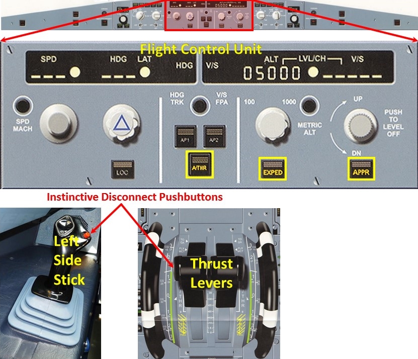
There were two EGPWS indicators and controls relevant to the unit’s operation. The instrument panel (Figure 4) includes the PULL UP warning light in the field of vision of both pilots.
Figure 4: B737-300 flight deck instrument panel EGPWS indicators and controls
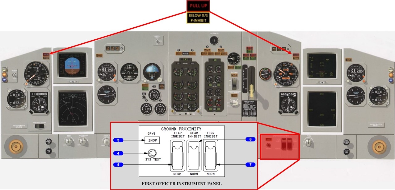
Source: Boeing, modified by the ATSB
The lower right section of the instrument panel included the GPWS controls. The terrain inhibit switch (7) in the NORM (guarded position) enabled EGPWS features. When selected to TERR INHIBIT, terrain/obstacle alerting was inhibited. Aircraft flight data identified that the first EGPWS alert had an associated inhibit signal. This inhibit signal was due to the flight crew selecting the terrain inhibit switch to ON following the first warning alert.
The Boeing 737 flight crew operations manual, which was the company’s approved reference, stated that the response for the TCF alerts was to correct the flight path, aircraft configuration, or airspeed. The manual also stated:
If a terrain caution occurs when flying under daylight VMC, and positive visual verification is made that no obstacle or terrain hazard exists, the alert may be regarded as cautionary and the approach may be continued.
The flight crew’s response to the first two EGPWS alerts did not appear to comply with the procedural requirements. The alerts did not occur in daylight VMC conditions and the crew’s visual reference with the runway or terrain was reported as intermittent. The crew’s response was stated to be due to the belief that the alert was the result of map shift issues and not because of ground proximity.
Comparison of FMS vs EGPWS position
The FMS did not have access to the EGPWS GPS information. The FMS recorded position of the aircraft at the time of the EGPWS alerts was compared against the position data recorded by the EGPWS. From the image below (Figure 5), it is evident that there was an FMS position error (approximately 1,065 m NW of the GPS position) at the time of EGPWS alerts. After the go-around, the FMS data appears to drift significantly (2,090 m north-north-west at landing), providing less reliable position information. It is important to note that the FMS derived position data was not required for the approach that was undertaken.
Figure 5: The flight data recorder data is shown below in blue and the EGPWS data is in red showing that, prior to the go-around, there was a 1.0 NM positional error to the flight management computer determined position
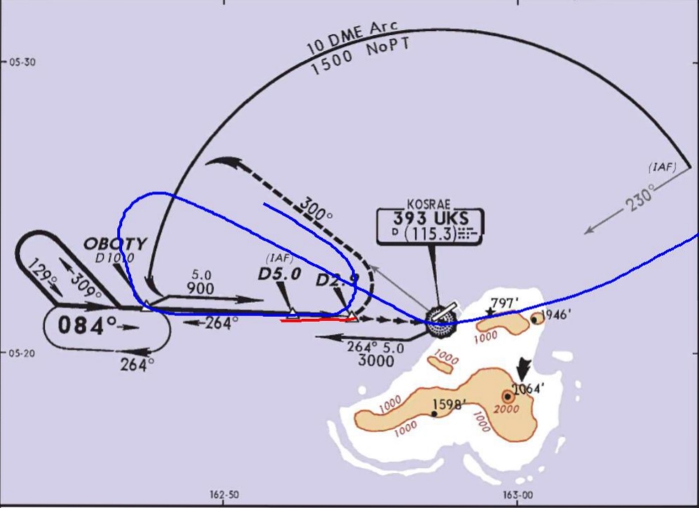
Source: Jeppesen, modified by the ATSB
Autothrottle go-around modes
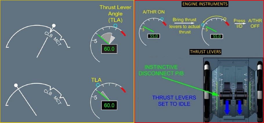
There were two autothrottle go-around modes, the autopilot (AP) go-around (which required dual AP operation) and Flight Director (FD) go-around (which is the reversion mode when both APs were not engaged). The FD go-around required the aircraft to be in flight and below 2,000 feet radio altitude, and not in the take-off mode. The flight crew operations manual included the following discussion concerning the FD go-around mode:
- With the first push of either take-off/go-around (TOGA) switch, the:
- autothrottle (if armed) engages in go-around and advances thrust toward the reduced go-around N1[12] to produce 1,000 to 2,000 fpm rate of climb
- autothrottle engaged mode annunciation on the flight mode annunciator (FMA) indicates go-around
- AP (if engaged) disengages
- pitch mode engages in TOGA and the pitch engaged mode annunciation on the FMA indicates TOGA
- FD pitch commands 15 degrees nose up until reaching programmed rate of climb, and thereafter commands manoeuvring speed for each flap setting based on maximum weight calculations.
- With the second push of either TOGA switch (if autothrottle engaged and after autothrottle reaches reduced go-around thrust), the autothrottle advances to the full go-around N1 limit.
The captain stated that he was not used to conducting a reduced thrust two engine go-around because he had always practiced a one-engine go-around in the simulator, which automatically provided full engine thrust from a single TOGA switch push. The captain stated that he had conducted a few full thrust go-arounds previously but in VMC conditions.
The Kosrae NDB/DME approach
The instrument approaches available for Kosrae were RNAV (GPS) approaches to runways 23 and 05, and the non-directional beacon (NDB) /distance measuring equipment (DME) approach. As VH-NLK was not fitted with GPS navigational equipment, the only instrument approach available to the flight was the NDB/DME approach.
The NDB/DME approach was classified as a circling approach only, due to the final approach course being offset from runway 05 heading by more than 30°. The missed approach point for this approach was at 2.9 DME with a minimum descent altitude of 500 ft.
According to the recorded data, prior to becoming established on the instrument approach, the aircraft overflew the NDB, turned onto the missed approach heading of about 300°, and then tracked outbound to the 10 DME arc before turning inbound on the 264° radial (see Figure 5). The recorded flight data identified that the aircraft descended below the published profile of 900 ft at 6.7 DME rather than 5 DME. The aircraft was required to remain at 500 ft until established on the final approach path for landing. However, the altimeter recorded 432 ft (radio altitude height of 306 ft) when the captain commenced the go-around.
Nauru Airlines procedures
Transition level
The flight crew reported that the transition level of FL 55 at Kosrae was lower than other ports in their network, which were typically FL 110 to FL 130. The crew stated that they had briefed the lower transition level prior to top of descent and had reminded themselves of the lower level while passing through FL 130. They also stated that the lower transition level, combined with increased crew workload on the approach due to deteriorating weather, led to the crew forgetting the approach checklist, therefore not setting the correct QNH.
The operator’s flight crew operating manual stated that setting the QNH during the descent required the local QNH to be set as the aircraft approached the transition level. Each pilot was required to call the exact altimeter indications and compare the indications to detect any discrepancy between instruments. Positive altimeter calls were also required to be carried out during the descent at FL 150, the transition level, and at 5,000 ft above aerodrome elevation.
As the local QNH was reported to be 1007 hPa and the crew left the QNH set at the standard pressure of 1013 hPa, the pilots’ altimeters were over-reading by 180 ft during the approach.
Instrument approach criteria
The company’s operations manual stated that ‘all approaches are to be flown in a stabilised manner with the aircraft established in the correct configuration no later than 1,000 ft above ground level for instrument approaches and 500 feet above ground level for visual approaches’.
The operations manual also required an NDB/DME approach to be flown using raw data.[13] A runway aligned GPS-based approach was available at Kosrae. At the time of the occurrence, the operator had established operational procedures for the use of GPS as the primary navigational aid for GPS-based approaches,[14] but the Civil Aviation Safety Authority had not authorised the operator to conduct RNAV (GPS) approaches.
The flight crew training manual (FCTM) specified that an approach was considered stabilised only when a number of criteria were met. Notably, these included:
- the aircraft requiring only small changes in heading and pitch to maintain the correct flight path
- the aircraft being in the correct landing configuration
- all briefings and checklists having been conducted.
It also stated that unique approach procedures or abnormal conditions resulting in a deviation from the above elements required a special briefing. This was the case with the Kosrae approach, which required the flight crew to use a ‘dive and drive’[15] technique due to the unique structure of the approach, and then circling to align the aircraft to the landing runway.
The FCTM also contained recommended procedures for the conduct of circling approaches. The FCTM procedures included that the circling approach be conducted with the aircraft configured with landing gear down and flap 15 selected. The aircraft was required to be in the final landing configuration before the aircraft was established on final approach.
The captain assessed that, due to the need to conduct circling manoeuvring following the approach, there was a need for a special briefing. The approach required pitch and power changes due to the need to manoeuvre the aircraft from the missed approach point of the instrument approach to a point where the aircraft would be aligned with the runway for the final approach to landing. The manoeuvring was the result of the offset between the instrument approach course and the runway. There was also the requirement that this manoeuvring be conducted as a visual segment, and the consideration that the visual slope guidance would only provide useable information once the aircraft was aligned with the runway.
The circling approach procedure resulted in the delayed selection of flap 25 until the aircraft was at 740 ft (altimeter) and landing flap not being selected during the approach. The crew reported initially gaining visual reference with the runway environment at 900 ft. While the aircraft did not meet the operator’s stabilised approach criteria, the unique nature of the circling approach and the captain’s special briefing removed the need for strict compliance with these requirements.
Meteorological information
Sunset at the Marshall Islands Airport (departure aerodrome) was 0652 with the end of civil twilight at 0715. Sunset at Kosrae Airport was 0723 with the end of civil twilight 0745.
The terminal forecast for Kosrae held by the flight crew was issued on 11 June at 2339 UTC. It covered the period of 12 June from 0000 to 2400 UTC and stated the wind direction as 80° at 7 kt, visibility greater than 6 statute miles and showers in the vicinity of the aerodrome (not at the aerodrome, but between 5 to 10 statute miles from the aerodrome). The weather forecast provided to the flight crew did not require an alternate to be planned; however, the flight crew reported carrying sufficient fuel for a diversion to Nauru.
An aerodrome weather report (METAR) for Kosrae was issued on 12 June at 0750 UTC, approximately 70 minutes prior to the aircraft arriving overhead Kosrae. It stated the wind direction as 80° at 10 kt, visibility greater than 10 statute miles. It also stated that cloud was scattered at 1,500 ft and broken at 13,000 ft. The METAR did not include a trend forecast and there was no other indication that the local weather conditions would deteriorate.
The flight crew stated that, as they approached Kosrae, the weather deteriorated rapidly. They received regular updates on the changes from the Kosrae flight information services (FIS). During the approach, visibility began to fluctuate at or below 3 to 3.5 NM, the crew lost visual reference with the runway necessitating a missed approach. The flight crew reported that the FIS advised that the local barometric pressure was 29.74 in Hg (1007 hPa).
Flight data recorder information
The aircraft’s quick access recorder provided data regarding the aircraft’s pressure altimeter and the radio altimeter readings. Pressure altimeter information was sourced from the aircraft’s air data computer and was based on the standard pressure altimeter setting of 1013 hPa. A comparison of this pressure altitude information with the recorded radio altimeter information indicated that, on average during the approach, the aircraft’s height was about 120 ft lower than the pressure altimeter’s altitude reading.
Fatigue, workload and stress
Fatigue
Fatigue can have a range of adverse influences on human performance, such as slowed reaction time, decreased work efficiency, reduced motivational drive, increased variability in work performance, and more lapses or errors of omission (Battelle Memorial Institute 1998). Gawron, French, and Funke (2001) contend mental, or cognitive, fatigue is more central to performance degradation than physical fatigue. They state that cognitive fatigue can be ‘inferred from decrements in performance on tasks requiring alertness and the manipulation and retrieval of information stored in memory.’ (p. 581).
Researchers (see Staal, 2004, for a review) have identified that visual scanning and attentional processes have been shown to be particularly sensitive to disruption from performance degradation due fatigue. In addition, most people generally underestimate their level of fatigue.
Sleep is vital for recovery from fatigue, with both the quantity and quality of sleep being important. It is generally agreed that most people need at least 7 to 8 hours of sleep each day to achieve maximum levels of alertness and performance. Some research has concluded that less than 5 hours sleep in the previous 24 hours is inconsistent with a safe system of work (Dawson and McCullough 2005) whereas other research has shown that having less than 6 hours sleep affects performance (Thomas and Ferguson 2010, Williamson and others 2011).
At the time of the occurrence, the operator managed fatigue through the processes of flight hour and duty time limitations as required under Civil Aviation Orders 48.0 and 48.1. The operator had developed a fatigue risk management system, however, it was in a draft stage and not approved for use by the Civil Aviation Safety Authority.
Workload and stress
Dismukes and Berman (2010) conducted research on flight crew checklist use and monitoring behaviour. These researchers found that most instances of failure to monitor the aircraft state or position resulted from competing concurrent task demands on the crew’s attention. Humans have a limited ability to divide attention among tasks and generally have to switch attention back and forth between tasks. This leaves an individual vulnerable to losing track of the status of one task while being engaged in another.
Workload has been defined as ‘reflecting the interaction between a specific individual and the demands imposed by a particular task. Workload represents the cost incurred by the human operator in achieving a particular level of performance’ (Orlady and Orlady, 1999, p.203). An individual has a finite set of mental resources they can assign to a set of tasks. These resources can change given the individual’s experience and training and the level of stress being experienced at the time. An individual will seek to perform at an optimum level of workload by balancing the demands of their tasks. When workload becomes excessive the individual must, as a result of their finite mental resources, shed tasks.
Under conditions of stress, an individual’s attention will channel or tunnel. Focus on peripheral tasks will be reduced and centralised on to main tasks. What differentiates a main task from a peripheral task depends on what the individual perceives to be of greatest importance or greatest salience. Tunnelling of attention can result in either enhanced performance or reduced performance, depending on the nature of the task and the situation. ‘When peripheral cues are irrelevant to task completion the ability to tune them out is likely to improve performance. On the other hand, when these peripheral cues are related to the task and their incorporation would otherwise facilitate success on the task, performance suffers when they are unattended’ (Staal, 2004, p.31).
Emotional states have been described as providing a third processing layer on top of cognitive and physiological levels. ‘Emotions play an important role in motivating people to initiate and maintain a task in the first place, but they may also interfere with cognitive processing. In particular, under time pressure or threatening conditions, the regulation of our emotions is critical for efficient task performance’ (Gaillard, 2001, p.626).
Research on risk associated with approach and landing
In the late 1990s, the Flight Safety Foundation established the Approach and Landing Accident Reduction (ALAR) task force. The task force was commissioned to, among other things, identify common factors in approach and landing accidents and serious incidents involving turbine powered aircraft of a weight greater than 5,700 kg, and develop processes and guidance to aid operators in the reduction of these types of occurrences.
The ALAR task force identified a number of factors that were significant and common to approach and landing accidents and serious incidents. Some of these factors were also present in this occurrence, including an approach in instrument meteorological conditions (IMC), at night, in an environment where radar was not available, and where the flight crew use a non-precision instrument approach procedure.
The guidance material produced by the task force included the ALAR Risk Awareness Tool (RAT). Designed to increase flight crew’s awareness of factors that can increase the risk of an accident during approach and landing, the RAT is designed to be integrated into the approach briefing normally conducted before commencement of the descent. There were a number of factors from the RAT that identified an elevated level of risk associated with the occurrence approach. These included:
- no ATC approach service or airport tower service
- non-precision approach, especially with a step down procedure or circling procedure
- visual approach in darkness
- hilly or mountainous terrain
- visibility restrictions, such as darkness or instrument meteorological conditions.
The RAT also makes the following point:
Greater risk is associated with conducting a nonprecision approach rather than a precision approach, and with conducting an approach in darkness and in IMC rather than in daylight and in VMC. The combined effects of two or more of these risk factors must be considered carefully.
The RAT also promotes the use of the missed approach or go-around manoeuvre when the safety of the approach or landing has become marginal, stating that ‘[f]ailure to recognize the need for a missed approach and to execute a missed approach is a major cause of approach-and-landing accidents’.
Related occurrences
ATSB investigation AO-2014-065 - incorrect configuration
On 31 March 2014, an Airbus A320 departed Auckland, New Zealand for a scheduled passenger flight to Gold Coast, Queensland. On departure from Auckland, where the local QNH was 1025 hPa, the crew selected the standard atmospheric pressure of 1013 hPa on the altimeters during climb to flight levels.
During the cruise, about 15 minutes prior to commencing the descent for the Gold Coast, the crew obtained the automatic terminal information service (ATIS) for Gold Coast and the captain wrote the details onto the take-off and landing data (TOLD) card, including the local barometric pressure of 1018 hPa. The crew then conducted the approach briefing, including a review of this information, which was entered into the flight management guidance computer (FMGC) for the approach.
Approaching transition altitude, the ‘BARO REF’ warning flashed, however, the captain was communicating with ATC, hence the page in the FMGC with the QNH displayed was not selected.
The captain then completed the communication with ATC and commenced the transition check by stating ‘transition’. At this time, the captain omitted to select the FMGC onto the flight plan page to display the QNH that had been entered. The first officer stated ‘set QNH 1025’ and the captain entered that into the second altimeter and the first officer entered the same value into the standby altimeter and a cross check confirmed that all three altimeters matched.
Passing about 1,000 ft AMSL, as the first officer completed the turn onto final approach, he observed the T-VASIS indicating a ‘fly-up’ profile. The radio altitude callout of 500 ft sounded and the first officer realised that the approach path was incorrect. When at about 159 ft above ground level, the EGPWS ‘TERRAIN’ warning sounded, and the first officer commenced the missed approach. The crew checked the QNH on the TOLD card and realised an incorrect QNH had been set.
International overview of go-around events
Although most go-arounds are conducted without significant problems, difficulties are experienced. As part of its detailed review of go-around issues, the French Bureau d’Enquêtes et d’Analyses pour la sécurité de l’aviation civile (BEA) (2013) conducted a survey of flight crews from several French and British airlines. Key results included:
- About 60 per cent of pilots indicated that they had encountered difficulties during the conduct of a go-around manoeuvre. The most common difficulties were capturing the go-around altitude, auto-flight system management, aircraft configuration management, coping with modifications to the flight path on ATC request and visual scan management.
- About 85 per cent of pilots reported that they were adequately trained in go-arounds with one engine inoperative but almost half the pilots indicated that they were not sufficiently trained for go-arounds with all engines operating.
The BEA’s analysis of the survey results stated that a key problem was:
The sudden onset of new tasks, the need to perform vital, rapid and varied manoeuvres, and the rapid changes in the numerous parameters to be managed (controlled) in a limited period of time combine to make it difficult for a crew to perform a go-around that is not controlled right from the start.
In its conclusions, the BEA stated that ‘aeroplane state awareness during go-around’ type events involved a combination of factors, including time pressure and a high workload; and the low number of go-arounds with all engines operating performed by crews, both in-flight and in the simulator. The BEA issued a significant number of recommendations to the European Aviation Safety Agency relating to go-around issues.
__________
- The aircraft was fitted with multiple Distance Measuring Equipment (DME) and Very High Frequency Omni Range (VOR) receivers that were able to be auto-tuned and used by the FMS for determining aircraft position.
- The rotational speed of the low-pressure compressor in a turbine engine.
- Aircraft navigation was to be made by sole reference to the NDB bearing and distance information from the DME. The operations manual also contained a requirement that, where the approach procedure was not contained within the flight management computer’s database, both pilots’ navigation displays were to be in the manual mode (a basic compass type display with limited navigational information from the flight management computers). The procedure used during the incident flight was contained within the database, and this requirement was not applicable.
- Although VH-NLK did not have GPS navigation equipment, two other aircraft in the operator’s fleet had been retro-fitted with navigation GPS equipment.
- Refers to the method by which an approach is flown where there are one or more stepdown fixes with minimum descent altitudes before the aircraft arrives at the missed approach point. The ‘dive and drive’ technique involves descending the aircraft to the segment’s lowest altitude then levelling off until the next stepdown point is reached. The technique involves multiple attitude and power changes during the approach, and is not consistent with the stabilised approach criteria, which can be achieved using a continuous descent profile.
Safety issues and actions
The safety issues identified during this investigation are listed in the Findings and Safety issues and actions sections of this report. The Australian Transport Safety Bureau (ATSB) expects that all safety issues identified by the investigation should be addressed by the relevant organisation(s). In addressing those issues, the ATSB prefers to encourage relevant organisation(s) to proactively initiate safety action, rather than to issue formal safety recommendations or safety advisory notices.
Depending on the level of risk of the safety issue, the extent of corrective action taken by the relevant organisation, or the desirability of directing a broad safety message to the [aviation, marine, rail - as applicable] industry, the ATSB may issue safety recommendations or safety advisory notices as part of the final report.
The initial public version of these safety issues and actions are repeated separately on the ATSB website to facilitate monitoring by interested parties. Where relevant the safety issues and actions will be updated on the ATSB website as information comes to hand.
Elevated risk from non-precision approach with low-level circling and non-stabilised approach procedure
Safety issue: AO-2015-066-SI-01
The operator commenced regular public transport operations into Kosrae with the only instrument approach available for use being an offset procedure based on a non-precision navigation aid. The risk associated with this type of approach was amplified due to the need to use a 'dive and drive' style technique instead of a stable approach path, and that it required low level circling manoeuvring from the instrument approach to align the aircraft with the runway. Furthermore, there was very high terrain in close proximity to the runway and the airport did not have a manned air traffic control tower. For this occurrence, the risk was further elevated as a result of the approach being conducted at night-time in poor weather conditions.
Additional safety action
Whether or not the ATSB identifies safety issues in the course of an investigation, relevant organisations may proactively initiate safety action in order to reduce their safety risk. The ATSB has been advised of the following proactive safety action in response to this occurrence.
Proactive safety action taken by: Nauru Airlines
On 18 September 2017, Nauru Airlines stated that they had addressed the recommendations they had made as part of their internal investigation report into the occurrence. The actions taken appear below:
- A review of the cyclic training program was undertaken by the Flight Standards Manager (FSM) with a focus on providing more flight crew training time to enable skill levels associated with non-standard/non-routine activities to be enhanced. The FSM has re-written the simulator program, changing it to two days twice a year in lieu of one day four times a year. This will provide flight crew with at least two full days of training instead of trying to fit training and checking in during a four-hour session. The training program has been drafted, but not yet implemented.
- A review of the descent and approach checklist card type, content and location was completed. A control column checklist incorporating tactile indicators was put into operation within weeks of the event.
- Two engine go-around training was included in the first simulator session following the event. This continues to be covered regularly.
- Performance based navigation (PBN) ground schools have reminded crew of QNH setting requirements. In addition, a pilot notice was issued to remind crew of the QNH validity period (15 minutes).
- A review of the options available for the most appropriate time to set the transition altitude QNH setting was undertaken soon after the event. The review identified that there is no foolproof method, and that this was a problem with most airlines. It was decided to stay with the current policy but increase training and checking of this procedure.
- For all flight standards meetings conducted after the event, discussions on events that could arise from not setting QNH at the transition altitude have been included. Also included are, discussions of different transition altitudes on the company network and the different types of terrain that could be encountered in the airline’s current and future network of operations. Terrain considerations are now mentioned in the operations manuals and will be incorporated in the new route manual.
- A review of the human factors and non-technical skills (HF-NTS) course content to include relevant points from this event into the applicable modules has been assigned.
- Soon after the event, additional emphasis was placed on the importance of correct briefing and NTS in line checks. This is now being carried out during line and simulator checks.
Purpose of safety investigations & publishing information
Purpose of safety investigationsThe objective of a safety investigation is to enhance transport safety. This is done through:
It is not a function of the ATSB to apportion blame or provide a means for determining liability. At the same time, an investigation report must include factual material of sufficient weight to support the analysis and findings. At all times the ATSB endeavours to balance the use of material that could imply adverse comment with the need to properly explain what happened, and why, in a fair and unbiased manner. The ATSB does not investigate for the purpose of taking administrative, regulatory or criminal action. TerminologyAn explanation of terminology used in ATSB investigation reports is available here. This includes terms such as occurrence, contributing factor, other factor that increased risk, and safety issue. Publishing informationReleased in accordance with section 25 of the Transport Safety Investigation Act 2003 Published by: Australian Transport Safety Bureau © Commonwealth of Australia 2018

Ownership of intellectual property rights in this publication Unless otherwise noted, copyright (and any other intellectual property rights, if any) in this report publication is owned by the Commonwealth of Australia. Creative Commons licence With the exception of the Coat of Arms, ATSB logo, and photos and graphics in which a third party holds copyright, this publication is licensed under a Creative Commons Attribution 3.0 Australia licence. Creative Commons Attribution 3.0 Australia Licence is a standard form licence agreement that allows you to copy, distribute, transmit and adapt this publication provided that you attribute the work. The ATSB’s preference is that you attribute this publication (and any material sourced from it) using the following wording: Source: Australian Transport Safety Bureau Copyright in material obtained from other agencies, private individuals or organisations, belongs to those agencies, individuals or organisations. Where you wish to use their material, you will need to contact them directly. |
Occurrence summary
| Investigation number | AO-2015-066 |
|---|---|
| Occurrence date | 12/06/2015 |
| Location | Kosrae International Airport, Federated States of Micronesia |
| State | International |
| Report release date | 16/03/2018 |
| Report status | Final |
| Investigation level | Systemic |
| Investigation type | Occurrence Investigation |
| Investigation status | Completed |
| Mode of transport | Aviation |
| Aviation occurrence category | Flight below minimum altitude |
| Occurrence class | Serious Incident |
| Highest injury level | None |
Aircraft details
| Manufacturer | The Boeing Company |
|---|---|
| Model | 737-33A |
| Registration | VH-NLK |
| Serial number | 23635 |
| Aircraft operator | Air Nauru |
| Sector | Jet |
| Operation type | Air Transport High Capacity |
| Departure point | Majuro, Republic of the Marshall Islands |
| Destination | Kosrae, Federated States of Micronesia |
| Damage | Nil |