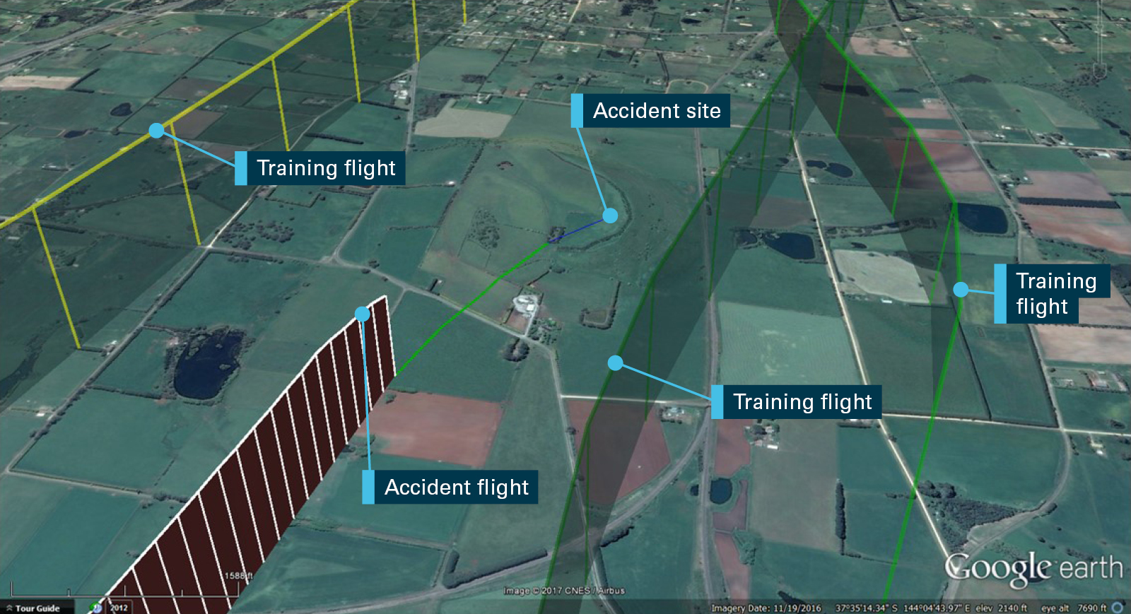
On 6 November 2015, at about 1829 Eastern Daylight Saving Time, the pilot of a Cessna Aircraft Company 310R registered VH‑BWZ, on a private flight from Moorabbin to Mildura, Victoria lost control of the aircraft near Mildura Airport and collided with terrain. The pilot was fatally injured and the aircraft destroyed.
What the ATSB found
Witnesses reported that when on final approach to land at Mildura, at low altitude, the aircraft yawed to the left, dropped its left wing and rapidly lost altitude. A number of factors contributed to the loss of control. The aircraft’s left engine was found to have been starved of fuel and at the time of the accident was not producing power. The left propeller was found to be towards fine pitch, not feathered (rotation of propeller blades to an edge-on angle to the airflow to minimise aircraft drag following an in-flight engine failure or shutdown), and the flaps and landing gear were fully extended, consistent with a normal landing configuration. In that configuration with the engine not producing power, the aircraft’s performance would have degraded to the extent that altitude could not be maintained.
The ATSB was unable to ascertain why the left engine was starved of fuel, nor could it be determined when the engine was starved of fuel. The ATSB did establish that it was likely the aircraft was carrying a substantial amount of fuel on board for continued flight and that the left engine and left propeller were capable of normal operation.
Several components recovered from the aircraft were tested. Some abnormalities were identified, however, it was unlikely that these contributed to the accident. No mechanical defects were identified that may have contributed to the accident. However, examination of the aircraft was limited due to the extent of the damage resulting from the post-impact fire.
It was likely that the combination of the inoperative left engine with the propeller in the fine pitch and the right engine at high power resulted in asymmetric thrust. Whilst at low altitude in a landing configuration with asymmetric thrust, the pilot lost control of the aircraft.
Safety message
In situations such as an inoperative engine condition, the aircraft’s landing gear, flaps and or propeller management can potentially impose increased drag impacting significantly on the aircraft’s performance. Low airspeed in critical phases of flight such as take-off and landing can further exacerbate the situation. Pilots need to train, maintain their skills and constantly monitor aircraft systems to be prepared for abnormal flight situations, especially during critical phases of flight where greater attentional focus is required.
While ATSB research has found that the rate of power loss accidents in multi-engine aircraft occur less than that in single-engine aircraft, they are more likely to be fatal and overwhelmingly due to the potential for loss of control. In particular, the approach phase of flight is considered riskier due to lower altitudes and lower available aircraft energy.
This accident has emphasised the adverse consequences of aircraft configuration on performance with one-engine inoperative, particularly when at low altitudes. It reinforced the importance of pilots remaining well versed in engine failure response procedures and being aware of the drag penalties associated with varying configurations. It also highlighted the challenges associated with recognising an asymmetric condition when in a descent or at a low power setting. When faced with an inoperative engine in a multi-engine aircraft, attention to both aircraft control and performance is crucial for safe flight.
The occurrence
On 3 November 2015, the pilot of a Cessna Aircraft Company 310R, registered VH-BWZ, departed Mildura, Victoria on a private flight to Latrobe Valley. The pilot had intended to return to Mildura the next day, however, due to poor weather, he elected to fly to Moorabbin. On 5 November, the pilot was again unable to return to Mildura due to poor weather and took the opportunity to have some minor maintenance performed on the aircraft while at Moorabbin where a wire was repaired to the tachometer.
On 6 November, at about 1650 Eastern Daylight-saving Time,[1] the pilot departed Moorabbin for Mildura, operating under instrument flight rules.[2] Despite the pilot having some difficulties shortly after departing, including a transient transponder code issue, navigating in poor weather and reporting a ‘downward force on the aircraft’, the pilot appeared to resolve these issues and stated to air traffic control (ATC) an intention ‘to continue to Mildura’. ATC subsequently issued vectors to depart Melbourne airspace for Mildura.
The flight between Melbourne and Mildura appeared to continue uneventfully. Airservices Australia surveillance radar data showed the aircraft tracking direct from Melbourne to Mildura at an altitude of 6,000 ft until radar services were no longer available.
While en route, the pilot sent several text messages, and telephoned the Mildura automatic weather information service and a family member. During this latter communication, the pilot indicated that he experienced difficulties while departing Moorabbin, however, the pilot did not state any specific mechanical defects or problems with the aircraft. The pilot was reported to have sounded normal during that conversation.
At about 1814, the pilot made a broadcast on the Melbourne Centre ATC frequency that the aircraft was 38 NM (70 km) from Mildura, at top of descent. No further broadcasts were made by the pilot on this frequency. It was unknown if the pilot made a call on the Mildura common traffic advisory frequency as broadcasts were not recorded.
Several witnesses situated to the south and east of Mildura Airport observed the aircraft approaching from the north, consistent with being on final approach to runway 18. One witness described the aircraft to be flying ‘in a nose-up attitude or yawing’.[3] At about 1829, when about 1.9 km north-north-east from the runway at low altitude, several witnesses described the aircraft as yawing left, the left wing dropping, the aircraft then rotating in an anti-clockwise direction and rapidly lose altitude before colliding with terrain.
The aircraft collided with steel trestles mounted on wooden poles that were strung with heavy gauge single strand wires, used to support grape vines. The aircraft came to rest on four strands of 11,000 volt high tension (HT) power lines that were strung across the property from the road. A post impact fuel-fire ensued. The pilot, the sole occupant, was fatally injured and the aircraft destroyed.
Pilot information
The pilot held a Private Pilot (Aeroplane) Licence issued on 25 June 2006. The pilot was endorsed on the Cessna 310 in September 2012 and last completed a multi-engine flight review in December 2013, valid until December 2015. The pilot was also the owner of VH-BWZ.
Extracts from the pilot’s logbook found at the accident site showed a total flying experience of about 511 hours. The pilot’s experience on the Cessna 310 was estimated at about 113 hours, based on a combination of entries on the aircraft’s maintenance release and the pilot’s logbook. It appeared that the pilot had not flown in the period February to October 2015. However, on 14 October 2015, the pilot completed an instrument landing system endorsement for the private instrument rating with a Civil Aviation Safety Authority (CASA) approved testing officer. During the endorsement, the pilot was subjected to several simulated one-engine inoperative exercises in the approach phase-of-flight. The testing officer reported that the pilot’s response to these exercises were considered ‘normal’.
The pilot held a valid Class 2 Medical Certificate with the requirement for reading correction to be available while exercising the privileges of the licence. While a post-mortem medical examination found that the pilot had a mild heart enlargement, there was no evidence of any pre-existing conditions identified that may have contributed to the accident.
The investigation included an assessment of whether the pilot may have been experiencing a level of fatigue known to have an effect on performance. Consideration was made of the pilot’s sleep obtained, time awake at the time of the occurrence, time on task, potential workload and environmental factors. However, given the limited data available in relation to the pilot’s sleep history in the 72 hours prior to the accident and the nature of the individual actions leading up to the accident, there was insufficient evidence to determine whether fatigue contributed to the accident.
Aircraft information
The aircraft was maintained by a provider approved by CASA. About 4 months prior to the accident, a periodic inspection was conducted and the aircraft was released to service. The maintenance provider reported that during the pre-maintenance engine run check the autopilot was operated while holding the elevator trim wheel. This test established that, while the autopilot was operating the trim could be arrested manually, establishing that the elevator trim could be overridden if unintentionally activated.
The aircraft’s fuel system consisted of two main tanks located on the tip of each wing and two auxiliary tanks located within each wing. The combined usable capacity was about 100 US Gallons (378 L) for the two main tanks, and 63 US Gallons (238 L) for the auxiliary tanks. The main tanks were integrally sealed aluminium tanks, which were vented to the atmosphere. Each auxiliary fuel tank consisted of two interconnected bladder-type fuel cells that were located between the wing spars in the outboard section of each wing.
Two fuel selectors, one for each engine, were located on the floor in between the pilot and co-pilot seats. These allowed selection of main tank fuel, auxiliary fuel, cross-feed and no fuel through the wing selector valves located in each respective wing.
Meteorological information
The Mildura aerodrome forecast, issued at 1613 and valid between 1700 on 6 November to 0500 on 7 November 2015 indicated that conditions were forecast as CAVOK[4] with a wind direction of 210° at 10 kt. The Bureau of Meteorology provided the ATSB with data recorded by the automatic weather station at Mildura which indicated at the time of the accident (1829), the wind was 220° at 11 kt gusting to 12 kt.
Wreckage and impact information
The aircraft was found in a left-wing, nose-down attitude and had come to rest on four strands of 11,000 volt HT power lines that were strung across the nearby property from the road. Ground scars of ruts, and soil and vegetation built up on one side of the landing gear and wings, indicated that the aircraft was rotating in an anti-clockwise direction during the impact sequence. The aircraft was destroyed by the impact forces and a post impact fuel-fed fire. The ATSB examined the wreckage and found:
The landing gear was down and flaps fully extended.
Continuity of all flight controls was established.
The elevator, rudder and aileron trims were found in the neutral position.
There was nil evidence of a pre-impact structural failure or in-flight fire.
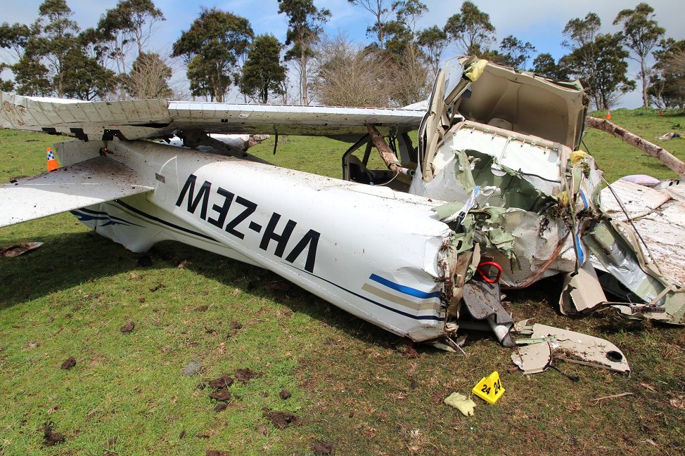
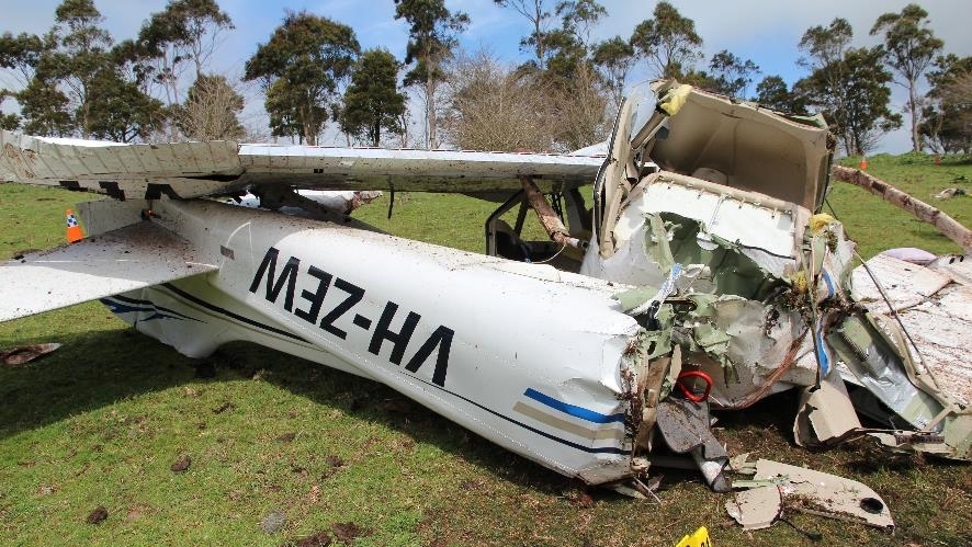
All fuel caps were identified in the wreckage in a closed locked position. The left wing main fuel tank was found attached to the left wing tip, while the right main tank had separated from the wing and had been thrown forward about 10 m. Both were significantly melted, consistent with the fuel-fed fire. The outer section of the right auxiliary fuel tank had fractured and separated due to the impact forces, and was found forward of the main wreckage, also significantly melted (Figure1). The inner section of the right wing auxiliary fuel tank did not burn and contained an adequate quantity of fuel to obtain a sample. That sample was field tested and found to be consistent with aviation fuel of a suitable quality. In contrast, the left auxiliary fuel tank displayed only some degree of melting. In consideration of the left wing-down attitude at the time of impact, it was unlikely that the left auxiliary fuel tank contained a significant quantity of fuel.
Figure 1 : Aircraft wreckage with evidence of fire and right wing auxiliary fuel tank in the foreground
Source: ATSB
The right engine propeller blades were towards the fine pitch[5] and displayed significant bending, torsional twisting and chord wise (across the width of the blade) scratching. The bolt holes of the engine crankshaft propeller flange, where the propeller mounted to the crankshaft with bolts and locating dowels, were elongated opposite to the direction to the crankshaft rotation. This was consistent with the right engine producing significant power when colliding with terrain.
The left engine propeller displayed no evidence of torsional bending or chord wise scoring, nor was the engine crankshaft propeller mount flange distorted. The angle of the propeller blades were consistent with being towards the fine pitch. In addition, one HT power line was found routed through the left propeller arc and engine cowling, then under the wing and through the landing gear. There was no evidence of the HT power line or the single strand wires used to support the grape vines being wrapped around the engine crankshaft. Similarly, there was evidence of arcing and mechanical abrasion on one of the propeller blades from contact with a HT power line while in-flight. This was limited to the leading edge of the propeller blade only. Collectively, these elements indicated that at the time of the collision the left engine was not producing power nor was the propeller producing thrust.
The cockpit and cabin were severely fire damaged, consistent with a significant fuel-fed fire supplied from the right inboard section of the auxiliary fuel tank.
The fuel selectors located in the cockpit were melted. Examination of the wing fuel selector valves, operated through push pull rods from the cockpit, showed that the right valve was selected to the right main fuel tank. In that position, the right engine received fuel from the right main fuel tank. The left wing fuel selector valve was in between the left auxiliary and cross-feed positions. The ATSB could not establish if that valve position was:
representative of the tank selection during normal operations,
selected in response to a left engine issue, or
a result of the impact sequence.
For each engine, the fuel line between the engine and fuel control unit and the engine and the wing were disconnected by the ATSB. The right engine fuel lines contained fuel. In contrast, no fuel was observed in the fuel lines of the left engine. No mechanical defects were identified that may have prevented normal operation of the left engine.
The source of ignition that led to the fire could not be established, however, the aircraft battery, damaged aircraft electrical wiring, hot engine and turbo charger, HT power lines and collision with steel were all possible sources of ignition. No mechanical defects were identified that may have contributed to the accident.
The left engine and propeller were recovered from the wreckage and transported to a CASA approved overhaul facility for detailed inspection under the supervision of the ATSB. The autopilot pitch and roll servos, and elevator trim actuator were also removed and sent to the United States for inspection under the supervision of the Federal Aviation Administration (FAA) and aircraft manufacturer. These components were tested in accordance with the manufacturer’s system of maintenance (refer to section titled Test and research).
Test and research
Left engine fuel system
The left engine fuel control fuel filter and fuel manifold top cap were removed and examined. No foreign object debris or fuel was identified in either component.
Left engine and propeller examination
Left engine internal components used to achieve normal engine operation, including the crankshaft, connecting rods, pistons, pushrods, cylinders, valves, camshaft, bearings and gears were inspected and found to have continuity. External accessories such as the fuel pump, magnetos, propeller governor and fuel injector were inspected and tested for correct operation. Other components such as the turbo charger and associated components were visually inspected.
The left propeller was also disassembled and inspected. Witness marks of the propeller blade situated in the cuff and bearing race damage found within the propeller established that, at the time of the collision, the propeller was towards the fine pitch position. Nothing was identified from those inspections or tests that may have prevented normal engine or propeller operation.
Autopilot pitch and roll servo, and elevator electric trim actuator
The servo drive motor for the autopilot pitch mode operated when power was applied. When an over voltage is detected in the system, the unit should trip the autopilot off-line and stop the motor; this function was inoperative. The motor clutch assembly was tested and slipped at 17 in lb in the clockwise direction and 21 in lb in the anti‑clockwise direction. The specification for this unit is 14 ±1 in lb in either direction. The actuator mount clutch on the capstan did not breakaway until 70 in lb in both directions. The specification for this clutch to slip is 20 ±2 in lbs.
The servo drive motor for the autopilot roll mode and the electric elevator trim actuator were also tested. Some minor breakout torque discrepancies were identified, however, were not considered significant.
Operational information
Fuel quantity
The pilot’s personal fuel records showed that 219.69 L was uplifted at Latrobe Valley on 4 November. The ATSB could not determine if that fuel was placed in the main and/or auxiliary fuel tanks. However, a witness at Latrobe Valley reported observing the main fuel tanks full. There were no fuel records identified to indicate any fuel uplift at Moorabbin.
The combined flight time from Latrobe Valley to Moorabbin and Moorabbin to Mildura was about 110 minutes, excluding taxi time. A pilot that had previously flown the aircraft reported that it had an average fuel burn rate of 60 litres per hour per engine (120 litres per hour total).
The Cessna Aircraft Company’s Pilot Safety and Warning Supplements, dated 1 June 1998, stated that:
Many twin engine Cessna airplanes incorporate auxiliary fuel tanks to increase range and endurance. These tanks are usually bladder type fuel cells located symmetrically in the outboard wing areas and contain no internal fuel pumps. When selected, the fuel from these tanks is routed to the engine driven fuel pump.
If the auxiliary fuel tanks are to be used, the pilot must first select main tank (tip tank) fuel for at least 90 minutes of flight with use of 63-gallon auxiliary fuel tanks. This is necessary to provide space in the main fuel tanks for vapour and fuel returned from the engine driven fuel pumps when operating on the auxiliary fuel tanks. If sufficient space is not available in the main tanks for this returned fuel, the tanks can overflow through the overboard fuel vents. Since part of the fuel from the auxiliary fuel tanks is diverted back to the main tanks instead of being consumed by the engines, the auxiliary tanks will empty sooner than may be anticipated. However, the main tank volume or quantity will be increased by the returned fuel.
As the ATSB was unable to establish the amount of total fuel on-board the aircraft when it departed Latrobe Valley or Moorabbin, or the pilot’s fuel management practices, the fuel remaining in each tank at the time of the accident could not be determined.
Asymmetric operations
The aircraft was fitted with two Teledyne Continental IO-520-MB piston engines and two three‑bladed McCauley propellers. Both engines rotated clockwise as viewed from the pilot’s seat.
When discussing the differences between single-engine and multi-engine aircraft, the FAA Airplane Flying Handbook (2016) stated that:
The basic difference between operating a multiengine airplane and a single-engine airplane is the potential problem involving an engine failure. The penalties for loss of an engine are twofold: performance and control. The most obvious problem is the loss of 50 percent of power, which reduces climb performance 80 to 90 percent, sometimes even more. The other is the control problem caused by the remaining thrust, which is now asymmetrical. Attention to both these factors is crucial for safe OEI [one-engine inoperative] flight.
The majority of light multi-engine aircraft such as the Cessna 310 have two wing-mounted engines that produce symmetrical propeller thrust during normal operation. One-engine inoperative operations on these aircraft result in asymmetric thrust and drag due to the offset position of the engines from the aircraft’s centreline. This results in a tendency for the nose of the aircraft to yaw in the direction of the inoperative engine. The extent of the yaw may vary depending on which engine becomes inoperative. The engine whose failure would most adversely affect an aircraft’s performance and handling qualities is termed the ‘critical’ engine. As the Cessna 310 engines turn in a clockwise direction, the left engine is the critical engine.
The asymmetric yawing tendency may be countered through the application of rudder and aileron control inputs. However, the minimum control speed of 80 kt[6] for the Cessna 310 must be achieved to ensure that the rudder and aileron retain sufficient control authority to maintain directional control of the aircraft. The Cessna 310 Pilot’s operating handbook stated that, the aircraft is controllable at this speed, but performance is so far below optimum that continued flight near the ground is improbable. Consequently, the handbook indicated that a more suitable recommended safe single-engine speed was 92 kt. At this speed, altitude could be maintained more easily with the landing gear retracted and the propeller feathered[7]. This speed is similar to the all engines landing approach speed of 93 kt with full flaps selected.
In addition, the CASA Civil Aviation Advisory Publication 5.23-1(2) stated that the majority of engine failures were not instantaneous. For example, if an engine failed as a result of fuel starvation or low fuel pressure, the engine will usually cough and splutter before stopping. However, the FAA recognised that:
An engine failure in a descent or other low power setting can be deceiving. The dramatic yaw and performance loss will be absent. At very low power settings, the pilot may not even be aware of a failure.
Pilot actions
The Cessna 310 Pilot’s operating handbook states that, following an engine failure, the pilot’s first consideration is to maintain control of the aircraft and ensure the airspeed remains above the minimum control speed. It then states that the pilot needs to identify the inoperative engine, adjust the operative engine as required, and perform a number of checks relating to fuel flow, tank selection and quantity; engine oil pressure and temperatures; magneto switches and mixture. If the engine does not re-start, the pilot must ‘secure’ or shutdown the engine, which includes feathering the propeller. The FAA flying handbook highlighted that completely securing a failed engine may not be necessary or even desirable depending upon the failure mode, altitude, and time available.
Aircraft performance degradation
The aircraft manufacturer advised that the Cessna 310 had a single-engine climb rate of about 375 feet per minute (at sea level and at maximum landing weight). However, with drag penalties of an unfeathered windmilling[8] propeller, landing gear extended and full flap, the aircraft’s single-engine climb performance would degrade. Under these conditions, one-engine inoperative performance would result in a descent at 875 feet per minute.
Various other sources have also highlighted these adverse consequences on aircraft single-engine performance. For example, Multi-Engine Pilot Manual by Jeppesen Sanderson (1992) stated:
It is important that the pilot be familiar with the correct order for drag reduction following an engine failure. Normally, a windmilling propeller contributes the greatest amount of drag, followed by full flaps, extended landing gear, and the control deflections required to stop the airplane from turning. Since it is considered unwise to immediately feather an engine before it has been positively identified, drag is normally reduced by first retracting flaps and gear. Next, the failed engine is identified and the propeller is feathered. However, the specific order of drag reduction may vary between types of twin‑engine airplanes, so the manufacturer’s recommendations should be followed.
Generally, the landing gear is not extended during the approach until the airplane is established at approach airspeed and the pilot is positively assured of reaching the desired runway. This timing is important since the extension of the landing gear adds sufficient drag to create a 300 to 500 f.p.m. [feet per minute] rate of descent without power reduction.
The wing flaps should be used as little as possible, preferably not at all until the landing gear is extended and the landing is assured.
The FAA Airplane Flying Handbook (2016) stated:
A single-engine go-around must be avoided. As a practical matter in single-engine approaches, once the airplane is on final approach with landing gear and flaps extended, it is committed to land on the intended runway, on another runway, a taxiway, or grassy infield. The light-twin does not have the performance to climb on one engine with landing gear and flaps extended. Considerable altitude is lost while maintaining VYSE[9] and retracting landing gear and flaps. Losses of 500 feet or more are not unusual. If the landing gear has been lowered with an alternate means of extension, retraction may not be possible, virtually negating any climb capability.
The CASA Civil Aviation Advisory Publication 5.23-1(2) stated:
A windmilling propeller causes the largest component of drag on an aircraft that suffers an engine failure. If the propeller is not feathered following an actual failure…the aircraft’s climb performance cannot be guaranteed. In many cases, it is likely that the aeroplane will only be able to maintain a descent.
Multi-engine power loss accidents
An ATSB research report, Power loss related accidents involving twin-engine aircraft (Research and analysis report B2005/0085), found that power loss accident rates in twin-engine aircraft were almost half of the rate for single-engine aircraft.[10] However, a power loss accident in a twin‑engine aircraft was more likely to be fatal and overwhelmingly the result of in-flight loss of control. Of the 58 accidents identified between 1993 and 2002 that resulted in damage following the power loss, seven accidents occurred during the approach phase of flight. Three of these involved a loss of control, including one fatal accident. Given the approach phase was a relatively small portion of the overall flight, this was considered a more risky time, with low altitude and only a little more energy available than during the take-off phase.
When on final approach to runway 18 at Mildura, witnesses reported seeing the accident aircraft at low altitude yaw to the left, followed by the left wing drop where the aircraft rapidly lost altitude. The aircraft subsequently impacted powerlines before colliding with terrain. The pilot was fatally injured, and the aircraft destroyed. The ATSB examined air traffic control recorded data, the aircraft wreckage, the pilot’s training and medical records, postmortem and toxicology reports, aircraft maintenance history and witness interviews. Aircraft components, including the left engine, left propeller and aircraft auto-pilot servo units were recovered from the wreckage for further examination.
The pilot was appropriately qualified to conduct the flight and was declared medically fit. Despite having relatively low flying hours on the aircraft type and twin-engine aircraft operations, the pilot demonstrated proficiency about one month prior to the accident where he completed an instrument landing system endorsement for the private instrument rating in the accident aircraft. During that endorsement he was subject to several simulated one-engine inoperative exercises during the approach phase for the ILS endorsement.
Four months prior to the accident, the maintenance provider performed a simple operational test of the autopilot and held the elevator trim wheel, proving that the elevator electric trim could be overridden manually. The ATSB did identify some anomalies with the auto-pilot elevator clutch assembly but could not determine if those abnormalities were pre-existing or were a result of the collision with terrain The ATSB did not consider the identified abnormalities factors contributing to the accident.
Examination of the left engine and propeller determined the engine was not producing power nor was the propeller producing thrust. This was most likely due to fuel starvation to that engine. No mechanical defects were identified that may have contributed to the occurrence. However, the examination of the wreckage was limited due to the extent of the fire damage sustained to the aircraft.
The following analysis will examine fuel starvation of the left engine and the subsequent power loss. The adverse consequence of this on aircraft performance, combined with the aircraft’s configuration, will also be discussed.
Left engine and fuel
Disassembly, inspection and examination of the left engine, left engine accessories and the left propeller at the accident site and during the post onsite detailed examination did not identify any mechanical defects or abnormalities that may have prevented normal engine or propeller operation.
However, examination of the engine fuel system identified no fuel in the left engine fuel manifold and supply fuel lines, which is situated between the wing fuel selector and the engine. The right fuel manifold and supply fuel line did contain fuel.
The aircraft departed Latrobe Valley with both main fuel tanks full, a total of at least 378 L of usable fuel on board. The flight time from Latrobe Valley to Mildura via Moorabbin was about 110 minutes. Based on that data and in consideration of an average fuel burn of 2 litres per minute, there should have been at least 158 litres of fuel remaining on board when the aircraft reached Mildura, not taking into account any fuel in the auxiliary fuel tanks. On that basis, it is likely that the aircraft had a significant amount of fuel on board at the time of the accident and the left engine had been starved of fuel.
The severe disruption of the left and right main fuel tanks and the right auxiliary fuel tank, including burning and melting indicated that those tanks held a significant amount of fuel at the time of the collision. In contrast, the left auxiliary fuel tank did not display the same level of disruption, including burning and melting of the aluminium structure or bladder fuel cell indicating that it is likely the left-wing auxiliary fuel tank did not have a significant quantity of fuel at the time of the accident.
The position of the wing fuel selector valves during flight was inconclusive as it could not be determined if the pilot had selected the fuel selector to the position found during the wreckage examination, or whether it was a result of the accident sequence.
The reason for the starvation of fuel to the left engine and the disparity of fuel quantity between the left and right auxiliary fuel tanks could not be quantified or determined due to the damage to the aircraft from impact forces and post impact fire.
Asymmetric condition
Witnesses observed the aircraft yawing to the left prior to loss of aircraft control and evidence located at the accident site showing the aircraft rotating in an anticlockwise direction during ground impact sequence was consistent with asymmetric thrust. It was likely the inoperative engine (which was the critical engine), with its propeller towards the fine pitch and the opposite engine at high power, resulted in an asymmetric thrust condition. To maintain control of the aircraft and counteract asymmetric thrust the pilot needed to apply rudder and if necessary the aileron to counteract the forces generated from the drag of the non-performing engine and high thrust from the performing engine. Rudder and aileron input also increases drag and contributes to the decay of airspeed.
Aircraft performance degraded
The ATSB could not determine when the engine failed, nor could it be determined if or when the pilot was aware of the failure. At the time of impact, the aircraft landing gear and flaps were fully down, the flight control trim devices were in the neutral position and both propellers were towards the fine pitch, consistent with a normal landing configuration. In this configuration, combined with the left engine not producing power the drag penalties were such that altitude could not be maintained.
It is possible that the pilot may have been in the initial stages of responding to the engine failure and was not in a position to secure the engine, which included feathering the propeller. Further, it is not known if the landing gear and flap positions were selected prior to the asymmetric condition in preparation for a normal landing or after, as the pilot may have believed an engine inoperative landing onto the runway could be assured. Irrespective, in this configuration the aircraft’s performance would have degraded to the point at which altitude could not be maintained to assure a landing.
This accident highlights the adverse consequences of aircraft configuration on one-engine inoperative performance, particularly when at low altitudes. It further demonstrates the challenges of asymmetric operations and the importance of pilots being aware of the drag penalties and associated consequences.
Findings
From the evidence available, the following findings are made regarding the collision with terrain involving a Cessna Aircraft Company 310R, registered VH-BWZ, which occurred 1.9 km north-north-east of Mildura Airport, Victoria, on 6 November 2015. These findings should not be read as apportioning blame or liability to any particular organisation or individual.
Contributing factors
For undetermined reasons the left engine was starved of fuel, which resulted in a loss of power during flight.
The left engine’s loss of power while the aircraft was in a landing configuration resulted in the pilot being unable to maintain aircraft control and the aircraft subsequently collided with terrain.
Sources and submissions
Sources of information
The sources of information during the investigation included:
Airservices Australia
a number of witnesses
Textron Aviation
the Civil Aviation Safety Authority
United States Federal Aviation Administration
Victoria Police.
References
Jeppesen Sanderson Inc 1992, Multi-Engine Pilot Manual, Jeppesen Sanderson, Colorado.
Submissions
Under Part 4, Division 2 (Investigation Reports), Section 26 of the Transport Safety Investigation Act 2003 (the Act), the Australian Transport Safety Bureau (ATSB) may provide a draft report, on a confidential basis, to any person whom the ATSB considers appropriate. Section 26 (1) (a) of the Act allows a person receiving a draft report to make submissions to the ATSB about the draft report.
A draft of this report was provided to the Civil Aviation Safety Authority, Airservices Australia, Textron Aviation, the aircraft maintenance provider, National Transportation Safety Board and the operator of the aircraft.
Submissions were received from the Civil Aviation Safety Authority. The submissions were reviewed and where considered appropriate, the text of the report was amended accordingly.
Purpose of safety investigations
The objective of a safety investigation is to enhance transport safety. This is done through:
identifying safety issues and facilitating safety action to address those issues
providing information about occurrences and their associated safety factors to facilitate learning within the transport industry.
It is not a function of the ATSB to apportion blame or provide a means for determining liability. At the same time, an investigation report must include factual material of sufficient weight to support the analysis and findings. At all times the ATSB endeavours to balance the use of material that could imply adverse comment with the need to properly explain what happened, and why, in a fair and unbiased manner. The ATSB does not investigate for the purpose of taking administrative, regulatory or criminal action.
Terminology
An explanation of terminology used in ATSB investigation reports is available here. This includes terms such as occurrence, contributing factor, other factor that increased risk, and safety issue.
Publishing information
Released in accordance with section 25 of the Transport Safety Investigation Act 2003
Ownership of intellectual property rights in this publication
Unless otherwise noted, copyright (and any other intellectual property rights, if any) in this report publication is owned by the Commonwealth of Australia.
Creative Commons licence
With the exception of the Coat of Arms, ATSB logo, and photos and graphics in which a third party holds copyright, this publication is licensed under a Creative Commons Attribution 3.0 Australia licence.
Creative Commons Attribution 3.0 Australia Licence is a standard form licence agreement that allows you to copy, distribute, transmit and adapt this publication provided that you attribute the work.
The ATSB’s preference is that you attribute this publication (and any material sourced from it) using the following wording: Source: Australian Transport Safety Bureau
Copyright in material obtained from other agencies, private individuals or organisations, belongs to those agencies, individuals or organisations. Where you wish to use their material, you will need to contact them directly.
On the afternoon of 2 November 2015, a Eurocopter AS350-BA helicopter, registered VH-SFX, was performing a low-altitude aerial weed spotting operation over dense forest in the Whyanbeel Valley, Queensland. On board the helicopter were the pilot, a navigator and two aerial spotters.
While conducting the work, the helicopter yawed twice in an uncommanded manner. In response, the pilot climbed and increased the helicopter’s forward airspeed and attempted to return to his base of operations. Subsequently, the engine failed, which required the pilot to conduct an autorotation and emergency landing.
The passengers adopted the brace position and the helicopter landed heavily with the skids digging into the uneven terrain and breaking off. The navigator in the front seat received minor injuries and the pilot received serious back injuries from the impact forces.
What the ATSB found
The ATSB found that the emergency landing was handled in a competent and proficient manner. The pre-departure briefing gave the passengers the necessary knowledge to prepare for the emergency by adopting the brace position and exiting the helicopter only when it was safe to do so.
Analysis of the engine identified that the aircraft lost power due to a front bearing failure in the turbine module. The failure was due to an accumulation of coke particles in an oil jet. The ATSB was unable to conclude specifically why the coke particles had formed.
The severity of the engine failure was increased through the fracture of the power turbine shaft and the subsequent separation of the turbine disc. This was due to a lack of adhesive on the splined nut that was threaded to the rear of the power turbine shaft.
A service information bulletin issued by the helicopter manufacturer in 2010 recommended that AS350 helicopter operators consider the safety benefits of installing energy-absorbing seats. Had these seats been installed, the forces imparted to the pilot during the accident sequence may have been reduced.
What's been done as a result
The engine manufacturer (Safran Helicopter Engines) has amended their procedure manual to include systematic cleaning of the power turbine front bearing assembly oil jet and oil jet supply pipe. Safran HE have initiated a number of training and process changes to ensure the adhesive bonding between the power turbine and the rear nut is maintained during service.
Safety message
This investigation highlights that responding to an emergency in a timely and proficient manner can minimise the consequences of an accident. Similarly, providing emergency procedures briefings enables passengers to react appropriately in an emergency.
In this occurrence, the reason for the engine oil jet coking leading to the engine failure was not specifically determined. However, a range of factors can affect engine oil coking. These factors should be considered to ensure normal ongoing engine operation.
The occurrence
On 2 November 2015, a Eurocopter AS350-BA helicopter, registered VH-SFX, was performing aerial work to identify noxious plants in dense forest within the Whyanbeel Valley (Figure 1), Queensland (Qld). The nature of the aerial work required the helicopter to operate at a low altitude and airspeed. On board the helicopter was the pilot, a navigator and two aerial spotters. The base of operations was in Mossman, Qld.
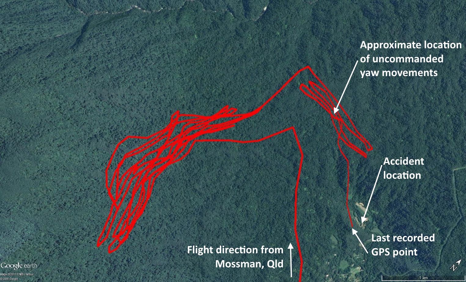
At approximately 1620 Eastern Standard Time,[1] during the fourth flight of the day, the helicopter momentarily yawed twice within a short period in an uncommanded and unusual way. The pilot, concerned with the uncommanded movements, ceased the operation, climbed and increased the helicopter’s forward airspeed. The pilot then elected to head back towards the base of operations (approximately 11km away) and, if required, land along the way if a suitably safe area along the flight path presented.
Shortly after, the chip detector light[2] illuminated on the instrument panel, prompting the pilot to search for a suitable landing area. As the helicopter continued to climb through approximately 200 ft, the engine stopped producing power.
The pilot identified the most suitable area to land, given the limited available height and airspeed, and commenced an emergency autorotation. The identified area was uneven, overgrown with plants, and surrounded by tall trees. During the landing sequence, the skids of the helicopter dug into the terrain and were broken off. The helicopter came to rest about 10 m after first touching down. The passengers received nil to minor injuries and waited until the rotor blades had ceased turning before evacuating the helicopter. The passengers then assisted the pilot who had received serious back injuries. The helicopter was substantially damaged.
Figure 1: The helicopter’s GPS track, arriving in the area of operations, its flight path around the forested terrain in the Whynabeel valley, and the accident site
The pilot held a valid Commercial Pilot (Helicopter) Licence that was issued on 6 January 2004 and a valid Class 1 Aviation Medical Certificate. The pilot’s last flight review was issued on 17 February 2014 and was valid until 29 February 2016.
The pilot had a total flying experience of about 6,200 hours, of which over 3,000 hours were in the AS350 series helicopter. This included a substantial amount of experience conducting low-level operations. In the previous 90 days, the pilot had flown 9 hours on type, and in the previous 24 hours the pilot had flown 6 hours on type. The pilot reported feeling rested and alert prior to the occurrence flight.
Helicopter information
The helicopter was a Eurocopter AS350-BA helicopter, manufactured in 1981 and first registered in Australia on 16 June 2005. At the time of the occurrence, the airframe had accumulated approximately 10,518 hours total time in service (TTIS).
Wreckage and impact information
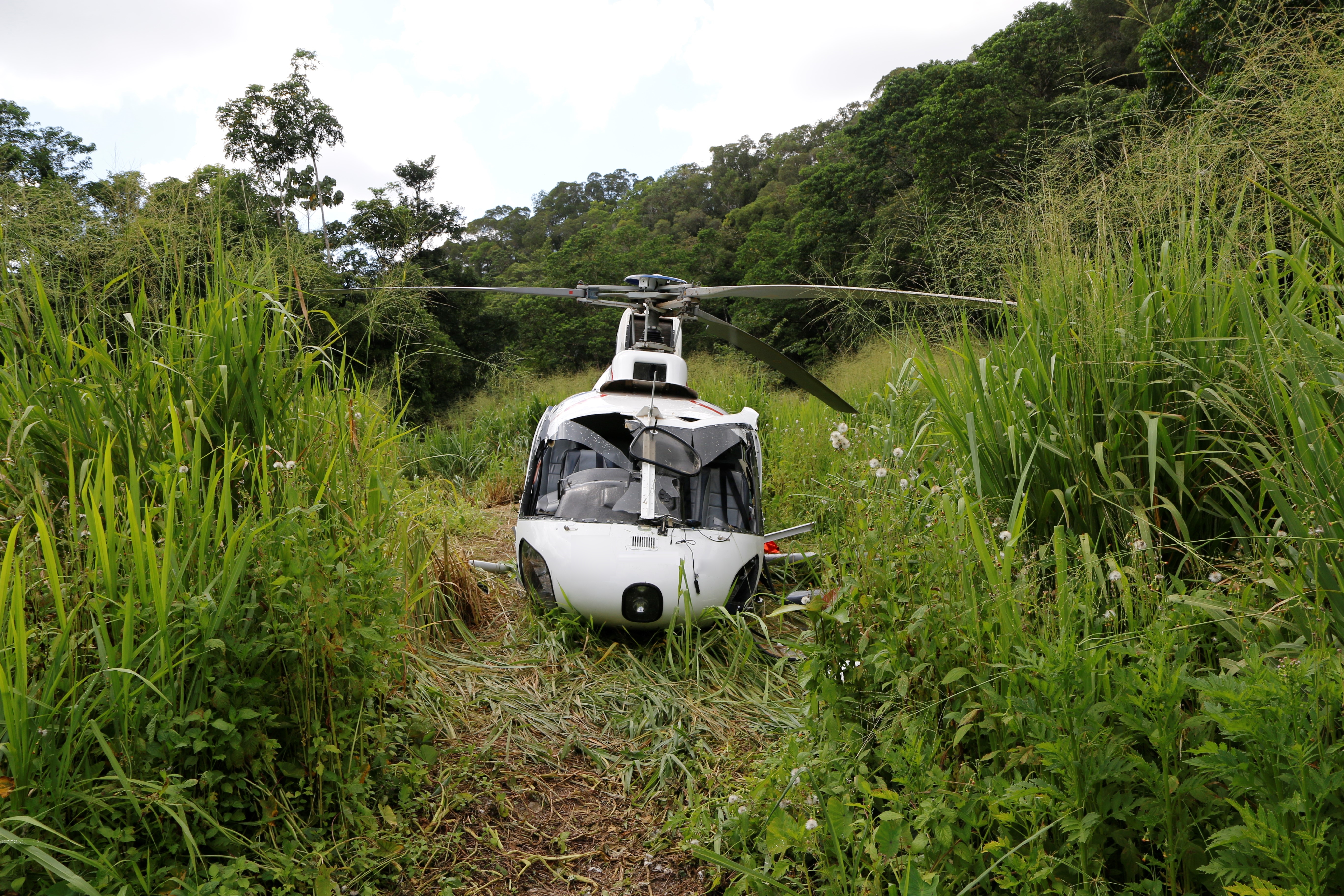
The on-site examination found that the helicopter struck the ground tail rotor first, with the skids subsequently digging into the uneven terrain and separating from the fuselage (Figure 2).
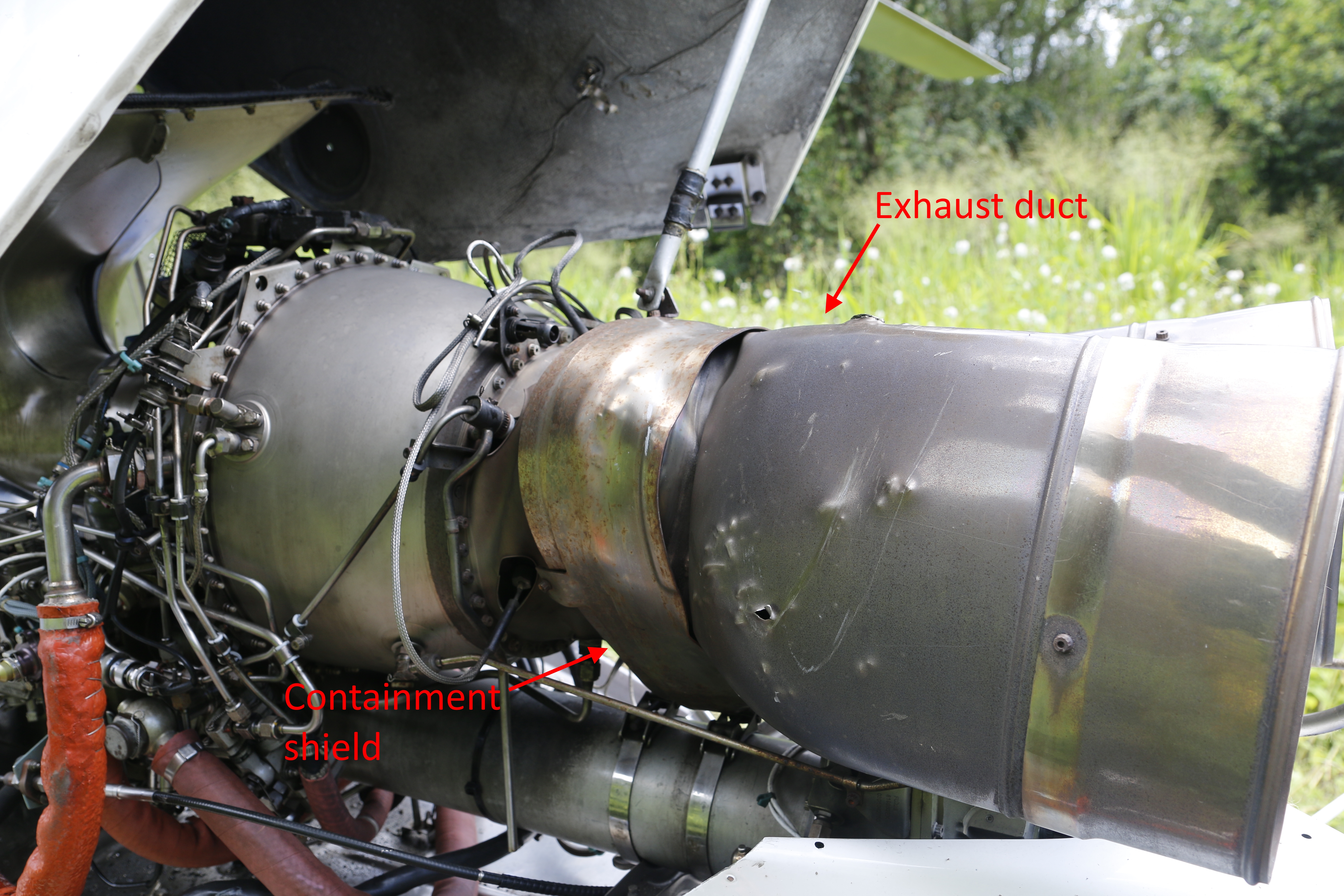
The engine had sustained damage consistent with a high-energy failure. The power turbine separated from the disc and the containment shield was twisted and deformed. The exhaust duct was bulged and puncture marks from internally liberated engine debris was evident (Figure 3).
Figure 2: VH-SFX at the accident site
Source: ATSB
Figure 3: View of the helicopter engine at the accident site
Source: ATSB
Engine information
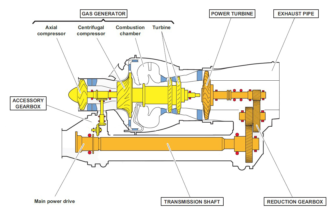
The helicopter was powered by a Turbomeca[3] Arriel (model 1B) engine, located above and to the rear of the passenger compartment. The Arriel 1B engines feature a modular design with the major modules consisting of an axial and centrifugal compressor, an annular combustion chamber, a two-stage axial turbine, a single-stage axial power turbine and a reduction gearbox (Figure 4). This occurrence related to a failure within the power turbine.
Figure 4: General arrangement of a Turbomeca Arriel 1B turboshaft engine showing the locations of the major sub-components
Source: Turbomeca, modified by the ATSB
Power turbine information
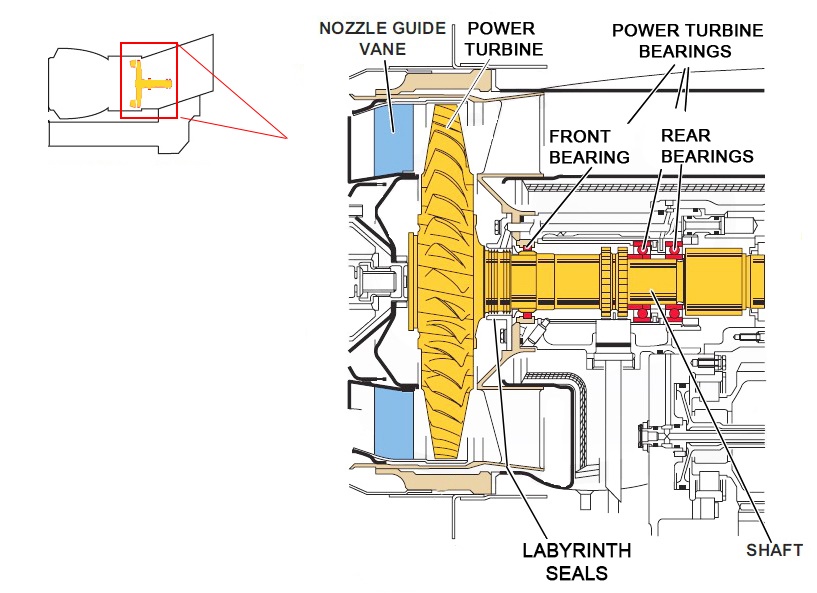
Gases from the two-stage axial turbine are directed downstream to the power turbine. The power turbine disc and shaft is a cantilevered design supported by front and rear bearings (Figure 5). Surrounding the power turbine is a containment shield to prevent high-energy engine debris from exiting the engine in the event of a blade fracture or disc separation from the shaft. The fractured turbines blades did not penetrate the containment shield in this occurrence.
Figure 5: General arrangement of the power turbine showing the relative location of the major parts including the guide vanes, labyrinth seal, power turbine shaft, rear nut, and the front and rear bearings
Source: Turbomeca, modified by the ATSB
Engine examination
The engine was removed from the helicopter and a preliminary examination was completed at the engine manufacturer’s facilities in Sydney, New South Wales. The power turbine shaft assembly of the engine was subsequently transported to the manufacturer’s facilities in France. The assembly was inspected in detail under the supervision of the French aviation investigation agency, the Bureau d'Enquêtes et d'Analyses pour la sécurité de l'aviation civile (BEA). The examination determined that:
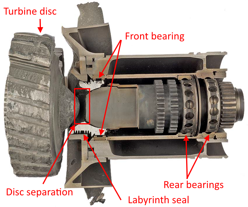
The power turbine disc had fractured in overstress and separated from the power turbine shaft (Figure 6). The power turbine disc sustained a complete loss of power and the turbine blades had separated from their respective stations. Fracture of many of the blade inter-recesses within the disc had also occurred.
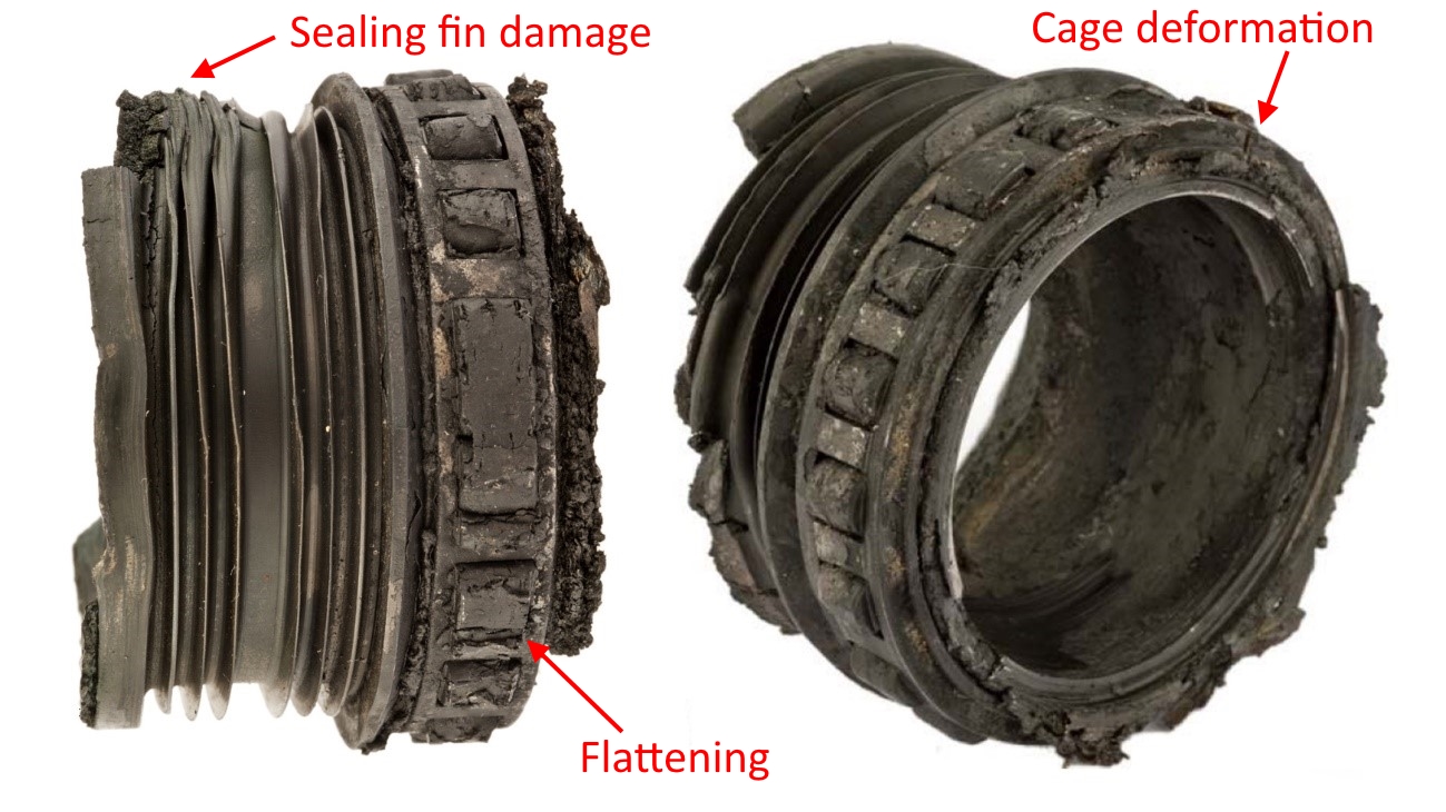
The front bearing of the power turbine shaft had totally seized (Figure 7). Evidence of roller skidding, metal contamination and gross overheating was found within the bearing assembly. The accumulation of hardened coking products and varnish deposits from oil degradation was also found within the rolling elements.
As a result of extreme frictional heating, the oil-air labyrinth seal, just forward of the front bearing, had melted and fused with the power turbine shaft.
Metallurgical analysis of the power turbine shaft showed that it had been exposed to temperatures in excess of 1,300C. That temperature was several hundred degrees above the normal maximum operating temperature of the engine.
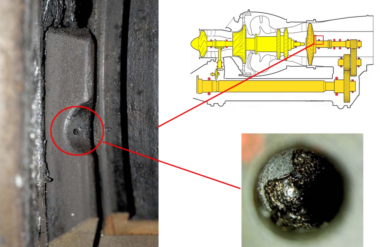
Examination of the oil jet and surrounding oil ducts to the front bearing of the power turbine shaft identified that the jet outlet was blocked with an accumulation of coke particles (Figure 8).
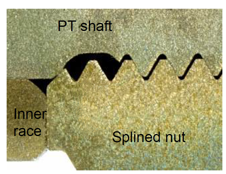
Examination of the splined nut that was threaded to the rear of the power turbine shaft assembly revealed evidence that it had tightened. The location of the nut determined the position of the shaft and any potential axial preload of the shaft bearings. No evidence was found of the adhesive that was required to have been applied between the threads on the rear shaft and the nut (Figure 9).
Figure 6: Cross-section through the power turbine assembly from the engine showing that the disc had separated from the shaft and the blades had fractured
Source: Turbomeca, modified by the ATSB
Figure 7: The seized front bearing and labyrinth seal, showing blackening from severe heat distress, flattening of the rollers, deformation of the cage and sealing fins
Image source: Turbomeca, modified by the ATSB
Figure 8: Close up of the blockage (circled) at the oil jet to the front bearing, as positioned in the general arrangement view
Image source: Turbomeca, modified by the ATSB
Figure 9: Cross-section of the rear splined nut contacting the rear bearing inner race
Source: Turbomeca
Power turbine rear nut adhesive bonding
The engine manufacturer had intended for an adhesive to be used in order to secure the rear nut into position. The adhesive was only applied during maintenance at a Turbomeca overhaul facility when the power turbine was overhauled.
Failure to adequately bond the nut could result in a tightening of the rear nut when abrupt changes in torque occur, leading to axial displacement of the turbine shaft in excess of the designed amount. This displacement would result in contact between the turbine shaft and the front bearing inner race, resulting in frictional heating, and damage to the turbine shaft.
The engine examination identified that the rear nut fitted to the rear of the power turbine shaft had not been adhesively bonded, as required.
Oil coking
The observed coking of the front bearing and its oil jet duct was likely a result of the engine oil exposure to abnormally high temperatures in the area. While there were clogging inspection procedures of the power turbine rear bearings, no preventative maintenance actions existed that allowed for the identification of coking within the front bearing.
Coking is an artefact from exposure to abnormally high temperatures that leads to oxidation and chemical breakdown of the oil. Coking can form as a thin-film layered deposit (as was the case in the oil duct) or in thicker clumps (which resulted in the clogging of the oil jet). It forms within the oil distribution channels and pipes, and can shed from the wall surface leading to reduced or obstructed oil flow. Determining the initiating source of coke formation is difficult as it can be attributed to a combination of influences, including:
operational conditions such as hot shutdown
design traits such as abrupt changes in oil flow direction and areas of low fluid velocity that can lead to reduced oil flow rates
low-drainage areas resulting in conductive or convective oil temperature increases post-shutdown
reductions in cross-sections such as scavenge ports that increase the likelihood of blockage
prolonged aircraft inactivity leading to moisture absorption of coke deposit.
The manufacturer of Arriel engines had published guidance for the thermal stabilisation of engines at shutdown. The guidance involved throttling the engine back until the engine was at ground idle for at least 30 seconds prior to shutdown. Stabilising an engine after operation allows for the temperature to reduce and thermally balance, while maintaining sufficient oil-scavenging capability and oil flow rates to minimise the potential for coke formation. Non-compliance with the manufacturer’s stabilisation recommendations may lead to coking.
The helicopter operator’s manual referred to the correct shutdown procedure in the AS350 flight manual. However, an appendix to the operator’s manual included a checklist that referred to a two-minute idle time before shutdown. The engine manufacturer advised that a two-minute shutdown would not adversely affect the formation of coke particles.
The engine manufacturer reported that a design trait of the power turbine is that the fluid velocity is lower at the bottom of the oil jet duct to the front bearing. For a given volume, this trait can lead to increased convective heating of the oil and depending on the temperatures in that region, may lead to coking.
In the period January 2000 to September 2015, there were 13 cases of Arriel engine deterioration in the power turbine shaft front bearing due to oil jet clogging. However, this is the only accident that has resulted in the failure of the turbine shaft.
Engine maintenance
The most recent significant maintenance involved removal of the engine from the airframe for repair after it sustained foreign object damage in February 2015 (7,786 hours TTIS). The centrifugal compressor and gas generator were replaced in May 2015. The engine was not operated during this period.
The last scheduled engine maintenance was performed on 30 October 2015 (8,060 hours TTIS), two days prior to the accident. Among the maintenance actions performed at that time, a clogging check of the gas generator rear bearing was conducted along with an inspection of the oil return line strainer. No anomalies were recorded in the maintenance documentation. The helicopter subsequently accumulated an additional 5 hours flight time up until the accident. There was no overdue maintenance requirements or declared defects.
Oil and filter analysis program
The helicopter operator had been monitoring the internal health of the engine components by participating in a spectrometric oil and filter analysis program (SOAP). That program relied on detecting the type and quantity of wear-material products within the engine oil and oil filter. The wear-material is generated from the breakdown mechanisms of internal engine components. SOAP checks were recommended by the engine manufacturer at intervals not exceeding 100 hours of service.
The most recent oil sample was collected and analysed approximately 10 hours prior to the engine failure. The previous sample to that was taken approximately 100 hours prior to the failure. Those checks indicated no unusual trends or signs that internal damage had been developing.
Emergency Procedures
The AS350 flight manual defined the emergency procedures for the illumination of the ‘ENG CHIP’ chip detector light and an autorotation landing. As per the AS350 flight manual, upon the Illumination of the ‘ENG CHIP’ caution light the pilot was required to:
“Land as soon as possible: land at the nearest site at which a safe landing can be made.”
A successful autorotation is dependent on the pilot’s airmanship and the helicopter’s speed and altitude relative to the airspeed-height envelope.
Airspeed-height envelope
The airspeed-height envelope defines a region within the helicopter’s flight envelope where there is insufficient energy (height and/or airspeed) for a successful autorotation to be completed. Section 5.1 of the AS350 flight manual defines the airspeed-height envelope for the helicopter. The envelope is determined using the density altitude and weight of the helicopter. The resulting envelope outlines the avoidance zone (Z); operating in the avoidance zone as defined in the FAA Rotorcraft Flying Handbook (FAA-H-8083-21A) ‘“may not allow enough time or altitude to enter a stabilised autorotative descent.’
Helicopters are not restricted from conducting operations in the avoidance zone, however, a pilot should always evaluate the risk of the manoeuvre versus the operational value.
In this case, the helicopter was equipped with a Garmin GPSMAP 195 portable device capable of storing track data for flights. During the operational portion of the flight, the helicopter was inside the avoidance zone. This was due to the aircraft being required to travel at a low airspeed and altitude such that the aerial spotters were able to identify the noxious plants.
The GPS track data for the accident ended while the aircraft was still airborne. At the time of the last track point, the aircraft was approximately 295 ft above the terrain travelling at approximately 65 kts groundspeed. This was outside the avoidance zone defined as per the flight manual.
Survival aspects
The passengers had received the pre-departure briefing and adopted the brace position. The navigator in the front seat received minor injuries and the pilot received serious back injuries from the impact forces. No objects were located underneath the front or rear seats.
Helicopter seating
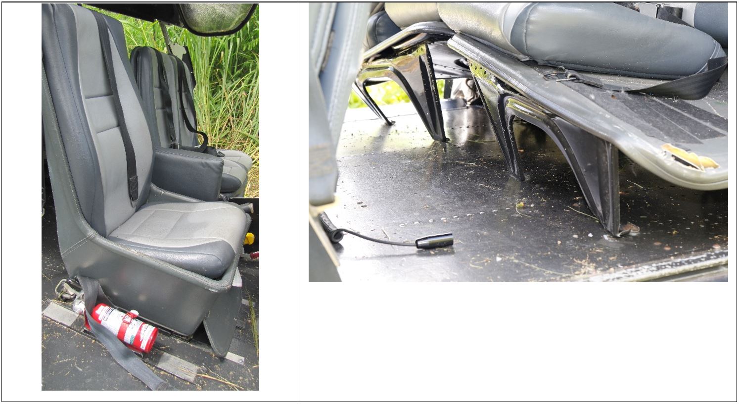
The helicopter was fitted with the original seats installed by the manufacturer (Figure 10). The rear passenger seats had deformed during the accident and likely absorbed some of the energy during the impact. The seat-belt attachments remained intact during the accident sequence. There was no observable deformation to the front seats of the helicopter.
In 1999, the helicopter manufacturer released a service letter (SL No. 1424-25-99) to inform all helicopter operators of the optional availability of redesigned seating for the pilot and copilot. The improved seat design increased the strength of the seat and attachments, and depending on the installed option, introduced energy-absorbing seat installations.
The manufacturer also published a service bulletin (EC SB AS350 No. 25.00.57) recommending the installation of the energy-absorbing seats on AS350 helicopters. A European Aviation Safety Authority (EASA) safety information bulletin, SIB 2010-05, reiterated the safety benefits associated with the installation of energy absorbing seats.
According to the EASA SIB, the modification of the helicopter in accordance with the SL would:
increase the pilot and co-pilot’s seat strength and crashworthiness and thus to provide an increased level of protection to the occupants in case of impact during an accident.
Figure 10: VH-SFX front seats (left) and rear passenger seats (right)
Emergency equipment
The helicopter was fitted with an emergency locator transmitter (ELT) that could be activated by a switch on the instrument panel, an emergency position indicating radio beacon, and a first aid kit. Just prior to touchdown the pilot activated the ELT. After the landing, two passengers proceeded on foot to search for persons/households to contact emergency services. About 30-45 minutes after the accident occurred, the passengers were met by emergency services, who were responding to the ELT transmissions. The pilot received medical treatment onsite and was transported to hospital for further treatment. There were no other communication devices available, such as a satellite phone, for contacting emergency services.
While conducting aerial weed spotting operations at low level, the helicopter’s engine failed necessitating an emergency landing into unfavourable terrain. The ground impact resulted in substantial damage to the helicopter. The pilot received serious injuries and the passengers sustained nil to minor injuries.
This analysis will examine why the engine failed, why an impending failure was not detected, the pilot’s handling of the emergency, and how occupant injuries can be reduced in the event of a hard landing.
Engine failure
The uncommanded yawing of the helicopter was the result of the engine failing from a seizure of the front bearing to the power turbine. The failure commenced rapidly when the oil supply to the front bearing became obstructed due to clogging of the bearing’s oil jet by the accumulation of coke particles (a solid residue from the breakdown of the engine oil).
During this period of transient engine operation, it is likely that the abrupt changes in torque from the power turbine and the lack of adhesive, led to a progressive tightening of the rear nut (fitted to the rear of the shaft). The tightening resulted in an axial coupling between the front bearing, stop, and labyrinth seal. That contact generated additional frictional heating and a further temperature rise within the shaft.
The combined effects of the front bearing seizure and the axial coupling of the components led to excessive heating and a subsequent critical reduction in mechanical properties for the shaft. Consequently, the turbine shaft was unable to sustain the operating stresses and it eventually fractured at the interconnection with the disc.
Oil coking
Coke formation is influenced by a range of complex factors (as mentioned in the coke formation section). The engine had been removed from the aircraft due to foreign object damage early in 2015 and spent several months out of operation. The ATSB was not able to determine if coke deposits were present at this point in time. Similarly, it was unknown if inactivity had impacted on moisture absorption of any coke deposits. The manufacturer has subsequently added an additional operation in their maintenance procedures which include the systematic cleaning of the turbine shaft front bearing assembly oil jet and oil jet supply.
While non-compliance with the stabilisation time before engine-shutdown can result in coke formation, the operator’s procedures, included a stabilisation time of not less than 30 seconds and it was reported that flight crew followed these procedures. As such, the ATSB was unable to determine to what extent (if any) the compliance with stabilisation times affected the formation of coke particles.
The service history of the Arriel-series engine indicates there have been multiple instances of deterioration of the turbine shaft front bearing as a result of the front oil jet clogging. The geometry around the oil jet was such that in the event of front bearing degradation due to clogging, temperature rises in this area would occur. This induced variations in the oil fluid velocity and led to conditions that were favourable to coking and the formation of hardened deposits. The use of the manufacturer specified oil and continuous monitoring for metal particles should have limited the effect of this phenomenon. However, the metal particle detection checks (SOAP) were not intended for assessing the presence of coke particles, but rather the breakdown of engine components. In this instance, clogging of the oil jet likely occurred before the breakdown of the engine components. The ATSB was unable to determine to what extent the geometry of the area affected the formation of coke particles.
Due to the complex combination of factors that can affect coke formation, the ATSB was unable to determine a specific source that led to the coke formation and oil clogging of the front oil jet.
Adhesive bonding of the power turbine rear nut
The engine manufacturer had intended for an adhesive be used in order to secure the rear nut into position. The adhesive was only applied during maintenance at a Turbomeca overhaul facility when the power turbine was overhauled. The engine examination identified that the rear nut fitted to the rear of the power turbine shaft had not been adhesively bonded, as required.
The engine would still have ceased operating if the appropriate adhesive had been present on the rear splined nut. However, the likelihood of the shaft failing would have been reduced and the failure sequence less severe. The failure sequence would likely have been extended, allowing greater time for the pilot to respond to the failing engine.
Flight operation
The operation necessitated the helicopter to operate at a low altitude and airspeed. At the time of the uncommanded yaw movements and subsequent ‘ENG CHIP’ light illumination, the helicopter was inside the avoidance zone. According to the helicopter operating manual, an ‘ENG CHIP’ light illumination necessitates the pilot to land the helicopter ‘as soon as possible’. This should be interpreted as soon as safe landing is possible. The pilot immediately increased airspeed and altitude and brought the aircraft out of the avoidance zone. This allowed the pilot to conduct a successful autorotation when the engine failed.
At the time, the helicopter was over densely forested and steep terrain, making it unsuitable for a safe landing. The pilot had elected to head back towards the base of operations (approximately 11 km away) and land if there was a suitably safe area along the flight path. Given the location of the helicopter and the surrounding terrain, returning to a known safe landing area (the base of operations), with the possibility of identifying a safe landing area during transit, provided an appropriate option in the difficult circumstances.
The pilot’s actions while responding to the emergency situation likely prevented serious injuries to the passengers.
Helicopter seating crashworthiness
The rear passengers had adopted the brace position prior to the impact and the seats had absorbed some of the energy from the hard landing. These passengers received nil injuries. Similarly, the passenger in the front seat braced for the landing and received only minor injuries.
The helicopter was fitted with the original front basic seats installed when it was manufactured. The basic seats complied with the minimum performance standard of the applicable certification bases.
As aerospace technology and design has evolved since the original certification, new certification rules have been enacted to better protect the occupant’s safety in the event of an accident. The manufacturer of the helicopter had installation options available to operators to install energy-absorbing seats. Energy absorbing seats reduce the amount of energy transferred to their occupants in the event of an accident.
In the case of this accident, there was not enough information on the impact forces and dynamics to determine whether energy-absorbing seats would have reduced the injury severity to the pilot.
Findings
From the evidence available, the following findings are made with respect to the engine failure involving a Eurocopter AS350BA helicopter, registered VH-SFX that occurred in the Whyanbeel Valley, Queensland on 2 November 2015. These findings should not be read as apportioning blame or liability to any particular organisation or individual.
Contributing factors
The helicopter lost power due to a failure of the Arriel 1B engine. The failure was a result of coke particles that had clogged the front oil jet from the power turbine shaft, preventing oil flow, and leading to a total seizure of the front bearing. The specific source that led to the coke formation and oil clogging of the front oil jet could not be determined.
The rear-splined rear nut had not been adhesively bonded to the power turbine shaft, as required. When the front bearing failed, the lack of adhesive led to a progressive tightening of the nut and additional frictional heating of the shaft from contact with the static engine components. The consequential reduction in material strength from the heating allowed the power turbine shaft to fracture and the disc to separate, further increasing the severity of the engine failure.
Other factors that increased risk
The helicopter was not fitted with energy absorbing front seats, which may have reduced the risk of injury to occupants during an accident.
Other findings
The ATSB found that the emergency landing was handled in a competent and proficient manner. The decision by the pilot to increase forward airspeed and altitude, after the uncommanded and unusual yaw movements, removed the helicopter from within the avoidance zone and likely prevented serious injuries to the passengers.
Safety issues and actions
Proactive safety action
Whether or not the ATSB identifies safety issues in the course of an investigation, relevant organisations may proactively initiate safety action in order to reduce their safety risk. The ATSB has been advised of the following proactive safety action in response to this occurrence.
The engine manufacturer (Safran Helicopter Engines) has amended their practices to include:
Periodic cleaning of the power turbine front bearing assembly oil jet and oil jet supply pipe. This reduces the occurrence probability for oil jet clogging by removing any accumulated deposits from these locations.
Degreasing of the threaded surfaces prior to application of the adhesive bonding and assembly of the parts. Maintenance and overhaul personnel have been informed of the importance of degreasing the surfaces before bonding the nut to the power turbine shaft.
Safran Helicopter Engines is also studying the use of heating equipment to obtain a more repeatable polymerization.
Sources and submissions
Sources of information
The sources of information during the investigation included the:
Safran Helicopter Engines (formerly Turbomeca)
Airbus Helicopters (formerly Eurocopter)
the Civil Aviation Safety Authority
the aircraft operator
the pilot
the passengers.
Submissions
Under Part 4, Division 2 (Investigation Reports), Section 26 of the Transport Safety Investigation Act 2003 (the Act), the Australian Transport Safety Bureau (ATSB) may provide a draft report, on a confidential basis, to any person whom the ATSB considers appropriate. Section 26 (1) (a) of the Act allows a person receiving a draft report to make submissions to the ATSB about the draft report.
A draft of this report was provided to the pilot, the passengers, the aircraft operator, the Civil Aviation Safety Authority, Airbus helicopters, Safran Helicopter Engines ,and the Bureau d'Enquêtes et d'Analyses pour la sécurité de l'aviation civile (BEA).
Submissions were received from the pilot, the aircraft operator, Safran Helicopter Engines, the Civil Aviation Safety Authority and the BEA. The submissions were reviewed and where considered appropriate, the text of the report was amended accordingly.
Purpose of safety investigations
The objective of a safety investigation is to enhance transport safety. This is done through:
identifying safety issues and facilitating safety action to address those issues
providing information about occurrences and their associated safety factors to facilitate learning within the transport industry.
It is not a function of the ATSB to apportion blame or provide a means for determining liability. At the same time, an investigation report must include factual material of sufficient weight to support the analysis and findings. At all times the ATSB endeavours to balance the use of material that could imply adverse comment with the need to properly explain what happened, and why, in a fair and unbiased manner. The ATSB does not investigate for the purpose of taking administrative, regulatory or criminal action.
Terminology
An explanation of terminology used in ATSB investigation reports is available here. This includes terms such as occurrence, contributing factor, other factor that increased risk, and safety issue.
Publishing information
Released in accordance with section 25 of the Transport Safety Investigation Act 2003
Ownership of intellectual property rights in this publication
Unless otherwise noted, copyright (and any other intellectual property rights, if any) in this report publication is owned by the Commonwealth of Australia.
Creative Commons licence
With the exception of the Coat of Arms, ATSB logo, and photos and graphics in which a third party holds copyright, this publication is licensed under a Creative Commons Attribution 3.0 Australia licence.
Creative Commons Attribution 3.0 Australia Licence is a standard form licence agreement that allows you to copy, distribute, transmit and adapt this publication provided that you attribute the work.
The ATSB’s preference is that you attribute this publication (and any material sourced from it) using the following wording: Source: Australian Transport Safety Bureau
Copyright in material obtained from other agencies, private individuals or organisations, belongs to those agencies, individuals or organisations. Where you wish to use their material, you will need to contact them directly.
On 29 May 2015, at about 1145 Eastern Standard Time (EST), a Victa 115 Airtourer aircraft, registered VH-MUV (MUV), departed from Leongatha Airport, Victoria, for crosswind circuit training, with an instructor and student on board.
The student pilot was flying the first circuit. The instructor reported that the circuit was normal and the approach was stable up to about 100 ft above ground level (AGL) when the student put the final stage of flap out. As the aircraft flared to land on runway 22, a strong gust of wind blew the aircraft off the runway centreline to the left and the aircraft bounced hard. The student initiated a go-around, applying full power, with the aircraft still drifting further to the left. As the aircraft was not climbing, the instructor called “taking over” and the student handed over control of the aircraft. The instructor lowered the nose of the aircraft to gain airspeed.
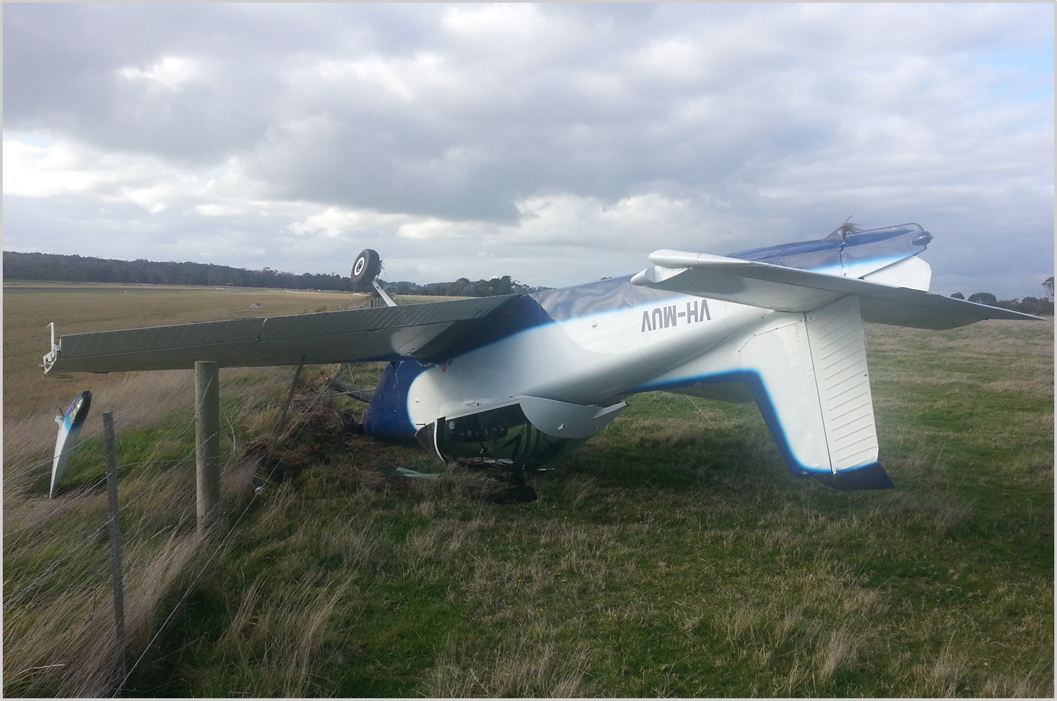
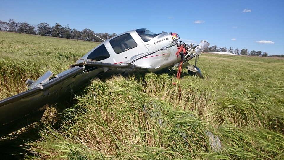
The aircraft continued to drift further away from the runway centreline. The student noticed the flaps were in the down position and, thinking that it would assist and without checking with the instructor, retracted the flaps to the up position. The aircraft descended and about 100 m past the threshold of runway 22, the aircraft collided with the airport perimeter fence. After a further 20 m, the aircraft flipped over the fence and came to rest upside down. The instructor and student exited the aircraft quickly through the broken canopy, as fuel was gushing from the fuel tanks. The instructor and student pilot received minor injuries and the aircraft was substantially damaged (Figure 1).
Figure 1: VH-MUV inverted after flipping over the airport perimeter fence
Source: Aircraft operator
Instructor comment
The instructor reported that the purpose of the flight was to instruct the student in crosswind landing techniques and then to conduct further flight training in the training area. The instructor indicated that, as they were planning to conduct 2 hours of flight training, the aircraft had full fuel on board and was near the aircraft maximum take-off weight.
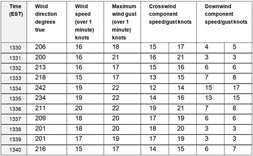
The instructor described the wind as gusting between 15 to 22 kt at 270 degrees, with a crosswind component of between 10 to 15 kt.
Safety action
Whether or not the ATSB identifies safety issues in the course of an investigation, relevant organisations may proactively initiate safety action in order to reduce their safety risk. The ATSB has been advised of the following safety action in response to this occurrence.
Flight training organisation
As a result of this accident, the flight training organisation advised the ATSB that they are taking the following safety actions:
The instructor has been briefed on the importance of making sure students understand not to touch any of the aircraft’s controls when the instructor is in control of the aircraft.
The instructor has been briefed on the handing over and taking over procedures with the emphasis on handing over and taking over controls procedures.
Safety message
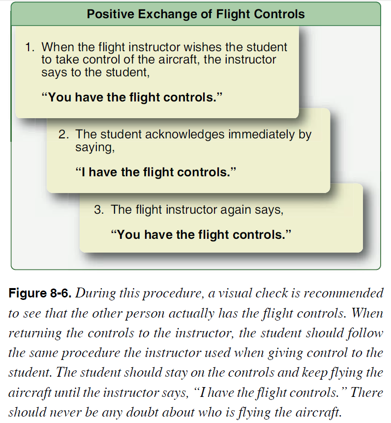
It is important in flight training to have a positive exchange of flight controls. The US Federal Aviation Administration (FAA) has found that numerous accidents have occurred due to a lack of communication or misunderstanding regarding who had actual control of the aircraft, particularly between students and flight instructors. The FAA publication Aviation Instructor’s Handbook, includes a section on the Positive Exchange of Flight Controls. The handbook provides guidance to use for the positive exchange of flight controls (Figure 2).
Figure 2: FAA Positive exchange of Flight Controls
Decisions regarding whether to conduct an investigation, and the scope of an investigation, are based on many factors, including the level of safety benefit likely to be obtained from an investigation. For this occurrence, a limited-scope, fact-gathering investigation was conducted in order to produce a short summary report, and allow for greater industry awareness of potential safety issues and possible safety actions.
Publishing information
Released in accordance with section 25 of the Transport Safety Investigation Act 2003
Ownership of intellectual property rights in this publication
Unless otherwise noted, copyright (and any other intellectual property rights, if any) in this report publication is owned by the Commonwealth of Australia.
Creative Commons licence
With the exception of the Coat of Arms, ATSB logo, and photos and graphics in which a third party holds copyright, this publication is licensed under a Creative Commons Attribution 3.0 Australia licence.
Creative Commons Attribution 3.0 Australia Licence is a standard form licence agreement that allows you to copy, distribute, transmit and adapt this publication provided that you attribute the work.
The ATSB’s preference is that you attribute this publication (and any material sourced from it) using the following wording: Source: Australian Transport Safety Bureau
Copyright in material obtained from other agencies, private individuals or organisations, belongs to those agencies, individuals or organisations. Where you wish to use their material, you will need to contact them directly.
Late in the afternoon of 7 October 2015, a pilot prepared the Robinson 44 helicopter, registered VH-ZWA (ZWA), for a solo training flight. The local flight from Darwin Airport, Northern Territory, was to consolidate the pilot’s knowledge of the local area, and become more familiar with the helicopter, as it was the pilot’s first day in a new job. Earlier in the day, the chief pilot had conducted an acceptance flight with the pilot in ZWA.
The pilot refuelled the helicopter and conducted a pre-flight inspection, before boarding, and completing the pre-start checklist.
The pilot then conducted the following engine start checklist from memory.
Engine start (main actions)
engaged the starter until it fired
engaged the clutch and turned the alternator on
when the clutch light went out, increased the rotor RPM to 79%
conducted a magneto check; and noted that all warning lights were out
began to increase the rotor RPM toward 100% and turned the governor on
Just as the pilot was about to conduct the next checklist item, a low rotor horn check[1], the pilot reported that the helicopter yawed slightly to the left. The pilot quickly checked that the pedals were neutral and put some ‘weight’ on the collective to confirm that it was fully down.
However, the helicopter continued to yaw left rapidly, through about 90° (Figure 1). The pilot applied full right pedal but the helicopter did not respond and continued the yaw, through about 180°, before falling onto its right side. The pilot, who sustained minor injuries, quickly exited the helicopter and the helicopter was substantially damaged (Figure 2).
Pilot experience
The pilot held a Commercial Pilot Licence (H) and a Private Pilot Licence (A). The pilot had logged about 340 hours in helicopters, with about 16 hours of these in the Robinson R44 and about 15 hours in the Robinson R22 helicopter.
Apart from the acceptance flight earlier that day, and a check flight a couple of weeks earlier, the pilot had not flown a R44 for more than three years. The pilot’s most recent helicopter experience was in a MD 520N helicopter. Although the pilot had flown two separate one-hour flights in the last three weeks, the pilot stated they were not current nor experienced on the R44. The pilot reported that flying opportunities had been limited, and spread out over about 4-5 years. During this time, the pilot had also worked as a helicopter support person and as a teacher of commercial helicopter theory subjects.
Figure 1: Skid marks made by VH-ZWA yawing to the left
Source: Operator
Figure 2: VH-ZWA on right side showing damage to main rotor and cabin
Source: Operator
Pilot comments
The pilot arrived from interstate at 0100 on the morning of the accident, ready to start the new job. They signed on for duty at 1000 after 7 hours of sleep. After completing some paperwork, the pilot underwent a one-hour company acceptance flight with the chief pilot. This flight was conducted in ZWA.
After a lunch break, more paperwork was completed before the chief pilot suggested the pilot go for a solo flight, to consolidate their knowledge of the local area and become more comfortable with the R44. The pilot reported feeling a little uncomfortable conducting the solo, but reasoned that it would be a good opportunity to gain some more practice. In addition, the pilot stated being slightly fatigued, and affected by the extra pressure of ‘new employee expectations’.
The pilot made a number of comments regarding different factors of the occurrence, these included:
at the time of the accident, not understanding why the helicopter turned to the left, or yawed so rapidly, particularly after full right pedal had been applied. The pilot later reflected that the pedals must not have been as neutral, as first thought and that this had allowed the yaw leading to the resultant loss of control
suggesting the left yaw may have been from the collective lock being jammed under the collective just enough for the control to feel fully down, but actually have sufficient play to allow the yawing movement.
felt that the helicopter falling onto the right side was consistent with dynamic rollover
Operator comments
The operator acknowledged that the new pilot had low total flying hours and low time on the R44 helicopter. This was combined with only 1.9 hours of flying logged in the last 90 days. Although two recent dual checks had been carried out, the additional solo practice was suggested to allow the pilot some consolidation time. In hindsight, the company realised that the pilot required even more dual time prior to being authorised for any solo practice.
A post-accident engineering inspection did not reveal any mechanical defects with ZWA.
ATSB comment
The ATSB did not conduct an onsite investigation to this accident. The pilot reported not being aware of making any errors during the engine start, but noted that a helicopter is unable to move if the collective is fully down.
In researching several databases for like occurrences, the ATSB found a Robinson 44 accident with similarities, in the United Kingdom. In this accident, the helicopter yawed to the left and fell onto the right side during an engine start. The UK Air Accidents Investigation Branch (AAIB) commented that a rapid yaw to the left could be induced, if too much left pedal is applied at the point of governor engagement, due to the effectiveness of the tail rotor.
The fact that the pilot’s most recent helicopter experience was on a MD 520N, also supports this possibility. The MD520N does not have a traditional tail rotor; it is fitted with a NO Tail Rotor (NOTAR) system, and requires very little pilot input on the pedals. It is probable that the pilot defaulted to this more relaxed pedal pressure during the accident flight.
Other R44 accidents, with relatively inexperienced solo pilots at the controls, were attributed to the pilot’s lack of recency, or inexperience, managing the different handling characteristics of the helicopter, due to the weight shift, which occurred without a person occupying the left seat.
Safety action
Whether or not the ATSB identifies safety issues in the course of an investigation, relevant organisations may proactively initiate safety action in order to reduce their safety risk. The ATSB has been advised of the following proactive safety action in response to this occurrence.
Operator
As a result of this occurrence, the aircraft operator has advised the ATSB that they are taking the following safety actions:
Operations manual amendment
All pilots recruited with under 500 hours total time and / or 30 hours in the previous 90 days, must fly with a Grade 1 instructor. This flight is to assess the pilot’s practical and mental status. The Grade 1 instructor is to provide a report on the flight to the Chief Pilot prior to the new pilot undergoing company induction.
Decisions regarding whether to conduct an investigation, and the scope of an investigation, are based on many factors, including the level of safety benefit likely to be obtained from an investigation. For this occurrence, a limited-scope, fact-gathering investigation was conducted in order to produce a short summary report, and allow for greater industry awareness of potential safety issues and possible safety actions.
Publishing information
Released in accordance with section 25 of the Transport Safety Investigation Act 2003
Ownership of intellectual property rights in this publication
Unless otherwise noted, copyright (and any other intellectual property rights, if any) in this report publication is owned by the Commonwealth of Australia.
Creative Commons licence
With the exception of the Coat of Arms, ATSB logo, and photos and graphics in which a third party holds copyright, this publication is licensed under a Creative Commons Attribution 3.0 Australia licence.
Creative Commons Attribution 3.0 Australia Licence is a standard form licence agreement that allows you to copy, distribute, transmit and adapt this publication provided that you attribute the work.
The ATSB’s preference is that you attribute this publication (and any material sourced from it) using the following wording: Source: Australian Transport Safety Bureau
Copyright in material obtained from other agencies, private individuals or organisations, belongs to those agencies, individuals or organisations. Where you wish to use their material, you will need to contact them directly.
On 28 June 2015, at about 1500 Central Standard Time (CST), a Robinson R22 helicopter, registered VH-RBO, took off from a property near Daly Waters, Northern Territory, for a local flight, including inspection of bores on the property. The temperature was about 30°C with a south-easterly wind at 10-15 kt. After flying for about 20 minutes, the pilot, who was the sole occupant of the helicopter, landed to open a gate and put out a bucket of chain. The pilot selected the governor off, then exited the helicopter, leaving the engine running. The pilot then re-boarded the helicopter and took off.
After a further 5 to 10 minutes of flight, when at about 100 ft above ground level, and an airspeed of 40 kt, the pilot conducted a turn to the south. The low rotor revolutions per minute (RPM) warning horn sounded. The pilot immediately wound the throttle fully open, and lowered the collective[1] to try to regain rotor RPM. The helicopter continued to descend. The pilot attempted to flare[2] the helicopter when low to the ground. The main rotor blades collided with tree branches. The helicopter landed heavily, the skids dug in to the soil and the helicopter rolled onto its side.
The pilot sustained minor injuries and the helicopter was substantially damaged (Figure 1).
Figure 1: Accident site
Source: Aircraft engineer
Pilot comments
The pilot was unsure whether the engine was running normally when the helicopter touched down, and could only recall hearing the rotor RPM warning horn. The pilot was focused on looking outside the helicopter at an earth tank and a mob of cattle and not inside at the instruments. The pilot reported that it was their normal procedure to switch off the governor when exiting, and then select it back on when returning to the helicopter. However, on this occasion, the pilot could not recall specifically switching it back on.
Engineering report
A 100-hourly maintenance inspection and the replacement of two cylinders was completed on the morning of the accident flight. The pilot and an engineer then conducted a flight of about 20 minutes duration, during which the helicopter performance and all indications were normal.
An initial inspection of the helicopter following the accident found the following:
No oil on the exterior of the engine or helicopter to indicate any oil line failure.
Fresh oil droplets on the right skid and a smear on the right strut. Immediately adjacent to the helicopter there was a small oil spill on the ground, probably from impact damage.
The fuel tanks still contained a substantial amount of fuel, which was leaking out down the mast.
Fuel from the drum was checked with no contamination found. The helicopter was fuelled with premium unleaded petrol.
Icing was found to have been unlikely.
Drive belts were still on and intact.
Clutch engagement position appeared normal.
Main rotor blades were buckled and damaged, partly from falling onto a fence, but were still attached to the hub.
Main rotor blades were evidently not turning fast when they hit the ground.
The engine was running on impact.
The governor switch was in the OFF position. The engineer turned on the master switch, and the governor light (GOV OFF) illuminated.
The engineer removed the main rotor blades and rolled the helicopter upright. The bottom spark plugs were removed and cleaned of oil, and then replaced. The engineer then started the engine and a positive oil pressure indicated. The engine was ground run for about 30 seconds and the magnetos, temperatures and pressure indicated normally.
Safety message
The Robinson Helicopter Company Safety Notice SN-24 states that rotor stall due to low RPM causes a very high percentage of helicopter accidents. These mostly occur close to the ground during take-off and landing. Safety Notice SN-10 reminds pilots to have their ‘reflexes conditioned so they will instantly add throttle and lower collective to maintain RPM in an emergency’.
Decisions regarding whether to conduct an investigation, and the scope of an investigation, are based on many factors, including the level of safety benefit likely to be obtained from an investigation. For this occurrence, a limited-scope, fact-gathering investigation was conducted in order to produce a short summary report, and allow for greater industry awareness of potential safety issues and possible safety actions.
Publishing information
Released in accordance with section 25 of the Transport Safety Investigation Act 2003
Ownership of intellectual property rights in this publication
Unless otherwise noted, copyright (and any other intellectual property rights, if any) in this report publication is owned by the Commonwealth of Australia.
Creative Commons licence
With the exception of the Coat of Arms, ATSB logo, and photos and graphics in which a third party holds copyright, this publication is licensed under a Creative Commons Attribution 3.0 Australia licence.
Creative Commons Attribution 3.0 Australia Licence is a standard form licence agreement that allows you to copy, distribute, transmit and adapt this publication provided that you attribute the work.
The ATSB’s preference is that you attribute this publication (and any material sourced from it) using the following wording: Source: Australian Transport Safety Bureau
Copyright in material obtained from other agencies, private individuals or organisations, belongs to those agencies, individuals or organisations. Where you wish to use their material, you will need to contact them directly.
Section 21 (2) of the Transport Safety Investigation Act 2003 (TSI Act) empowers the Australian Transport Safety Bureau (ATSB) to discontinue an investigation into a transport safety matter at any time. Section 21 (3) of the TSI Act requires the ATSB to publish a statement setting out the reasons for discontinuing an investigation.
On 6 October 2015, the ATSB commenced an investigation into a collision with terrain involving a Cessna 172, registered VH-IMY, 27 km NW of Landor Racecourse, Western Australia, which occurred on 3 October 2015.
The ATSB was unable to establish sufficient information to draw any specific conclusions regarding the circumstances of the accident, but is satisfied that there are unlikely to be any broad systemic safety issues associated with the accident that could affect future transport safety. On that basis, the ATSB determined that there was limited safety benefit in continuing to direct resources at this investigation when compared with other priorities and elected to discontinue this investigation.
On 17 September 2015, at about 1330 Eastern Standard Time (EST), the pilot of a Cirrus SR22 aircraft, registered VH-OPX (OPX), conducted a short flight from Moree Airport, New South Wales, to a private airstrip about 6 NM to the north. The pilot was the sole occupant of the aircraft.
The aircraft approached the airstrip from the south, and the pilot elected to overfly the runway at the eastern end, then turn left and join the circuit on a left downwind for runway 09. The pilot had observed the wind at Moree Airport to be from a southerly direction at about 15 kt, and therefore anticipated having a crosswind for the landing at the airstrip.
The pilot reported that the circuit and approach were normal. On final approach, the pilot extended full flap, and commenced the flare at an airspeed of about 80-90 kt. To align the aircraft with the runway, the pilot reported applying almost full left rudder and right aileron due to the crosswind.
The right main landing gear touched down first, and the aircraft bounced back into the air. The pilot immediately applied full power to initiate a go-around. However, the left wing dropped and the aircraft yawed to the left. The aircraft’s left wing and propeller then collided with a dam wall (Figure 1). The aircraft stopped abruptly and spun around. The engine separated from the aircraft and came to rest about 20 m away, the tail broke off and the nose landing gear collapsed. The pilot suffered minor injuries, and the aircraft sustained substantial damage (Figure 2).
Figure 1: Accident site
Source: Google earth – annotated by the ATSB
Figure 2: Damage to VH-OPX
Source: NSW Police Force
Pilot experience
The pilot held a private pilot licence and had about 1,400 hours of aviation experience, with 80 hours experience in the Cirrus aircraft. The pilot had not flown into that airstrip before the accident flight.
Airstrip information
Prior to conducting the flight to the private airstrip, the pilot contacted the owner and obtained information about the runway condition.
The runway was about 850 m long – unsealed for about 150 m at the western end, then sealed with bitumen for about 700 m. The runway was situated east-west, and the pilot elected to land towards the east. The aircraft initially touched down on the dirt, just prior to the start of the sealed part of the runway, which was slightly beyond where the pilot anticipated it to land.
As the aircraft overflew the runway, the pilot looked for, but did not see, a windsock by which to verify the conditions at the airstrip. The owner of the airstrip reported that there were three windsocks located at various positions near the runway.
Wind
The Bureau of Meteorology provided the ATSB with the wind recorded at Moree Airport. Table 1 depicts the calculated downwind and crosswind components based on the runway direction of 090° magnetic (101° true) of the airstrip 6 NM north of Moree. As seen in the table, at 1334, a significant wind gust of 22 kt from 242°, would have equated to a downwind component of 17 kt and a crosswind of 15 kt. If the aircraft had encountered similar conditions during the landing, this may have affected the pilot’s ability to control the aircraft.
Table 1: Wind direction, speed, gusts and calculated downwind and crosswind components
Safety message
This incident highlights the importance of the identification and management of risks associated with operating into unfamiliar airfields. Pilots should carefully assess the environmental conditions, runway surface and surrounds before attempting to land at an airfield.
The Civil Aviation Safety Authority Out-N-Back video Aircraft landing areas and precautionary search and landing, stated: ‘A precautionary inspection of an unfamiliar airstrip before landing is a logical and effective way to satisfy yourself that you have chosen a suitable landing area for your aircraft, and for your skill level’. This airborne inspection includes assessing the wind velocity and direction, and whether any terrain surrounding the field may affect a go-around.
Decisions regarding whether to conduct an investigation, and the scope of an investigation, are based on many factors, including the level of safety benefit likely to be obtained from an investigation. For this occurrence, a limited-scope, fact-gathering investigation was conducted in order to produce a short summary report, and allow for greater industry awareness of potential safety issues and possible safety actions.
Publishing information
Released in accordance with section 25 of the Transport Safety Investigation Act 2003
Ownership of intellectual property rights in this publication
Unless otherwise noted, copyright (and any other intellectual property rights, if any) in this report publication is owned by the Commonwealth of Australia.
Creative Commons licence
With the exception of the Coat of Arms, ATSB logo, and photos and graphics in which a third party holds copyright, this publication is licensed under a Creative Commons Attribution 3.0 Australia licence.
Creative Commons Attribution 3.0 Australia Licence is a standard form licence agreement that allows you to copy, distribute, transmit and adapt this publication provided that you attribute the work.
The ATSB’s preference is that you attribute this publication (and any material sourced from it) using the following wording: Source: Australian Transport Safety Bureau
Copyright in material obtained from other agencies, private individuals or organisations, belongs to those agencies, individuals or organisations. Where you wish to use their material, you will need to contact them directly.
On 17 September 2015, the pilot of an Air Tractor 502B aircraft, registered VH-FNX, was conducting aerial application (spraying) operations on a property about 23 km to the west of Hay Aerodrome, New South Wales. The spray application area consisted of a block of nine adjoining paddocks, separated by combination of irrigation channels and access roads that allowed for movement of plant and equipment. There was a single paddock included in the spray application area that joined the larger block at the eastern end, separated from the other paddocks by an irrigation channel. The pilot planned to spray the group of paddocks as a single block (Figure 1).
Figure 1: Spray application area - a block of nine paddocks with another adjoining paddock at the eastern end
Source: Google earth (supplied by the agricultural company and annotated by the ATSB)
As per normal procedure, while en route to the spray application area, the pilot had made a broadcast on UHF Channel 25 advising that spraying operations were about to commence, and also, the area where that would occur. UHF Channel 25 was monitored by employees on the property, and used for general communications.
At the time the pilot made the broadcast, there was a tractor operating in the southern part of the spray application area, and the tractor driver responded to the pilot’s broadcast. The pilot determined that although the tractor was inside the spray application area, there was no likelihood of an immediate conflict with the spraying operations. Due the southerly wind, the pilot intended to commence spraying runs along the northern edge of the block and gradually work toward the south. The pilot advised the tractor driver that they would be able to safely continue in that southern area, without creating any conflict for spraying operations, for about an hour. Without hearing any other responses to the broadcast, the pilot switched to a different UHF frequency (Channel 20), in accordance with their normal practice.
The pilot commenced spraying operations at about 1100 Eastern Standard Time (EST). The pilot was flying a left hand racetrack pattern, in an east-west direction; moving the pattern further south with each spray run. After a short time, the pilot departed the spray application area to reload with more chemical mixture at a nearby property.
The pilot then returned to the spray allocation area, and resumed spraying operations at about 1130. The pilot did not make another UHF radio broadcast upon the resumption of spraying operations.
At about 1145, as part of the continual southerly movement of the race-track spray pattern, the pilot was conducting a spray run in an easterly direction, along a roadway that divided some of the paddocks inside the spray application area. The pilot intended to continue the run, across the irrigation channel, and along the southern boundary of the eastern most paddock in the spray area (Figure 2).
During this run, the pilot reported seeing a white Toyota Hilux Double Cab utility vehicle turn onto an irrigation channel crossing ahead of the aircraft (Figure 2). However, the Hilux appeared to the pilot to be slowing to a stop, short of the intersection/irrigation channel crossing. The pilot assumed that the driver of the Hilux had seen the aircraft, and was stopping to allow the aircraft to continue its run over the channel crossing.
Figure 2: Layout of accident site, showing path of the aircraft, path of the tractor and Hilux along the irrigation channel bank, the south-eastern border of the spray application area, and the point where the collision occurred
Source: Google earth (supplied by the agricultural company and annotated by the ATSB)
Confident that the vehicle was stopping, the pilot continued the spray run and, as per normal routine, checked the spray pressure gauge, and momentarily looked to each side of the aircraft to confirm that no spray nozzles were blocked. As the pilot then turned their attention forward again, and commenced a short climb to clear the raised channel bank,[1] they saw that the Hilux had not stopped, but had continued along the road, turned right, and was climbing up over the raised channel bank. (Note: the agricultural company report advised that the tractor was ahead of the Hilux and already moving down the other side of the channel bank at this stage – refer section titled ‘Movement of Hilux’).
The pilot immediately stopped the spray and continued to climb, but was unable to clear the Hilux. The left wheel of the aircraft struck the tray headboard of the Hilux. As the vehicle and aircraft were both heading east, the aircraft struck the Hilux from behind.
Following the collision, the pilot climbed the aircraft to a higher altitude. The pilot checked that the aircraft was handling normally, including a brake pressure check, to confirm that the landing gear was still attached. The pilot saw that the driver had exited the vehicle, so made a broadcast on UHF Channel 25, advising farm personnel of the accident and requesting assistance for the driver. The driver of the vehicle responded to that broadcast. The pilot then flew back to the loading area and conducted a fly-by to enable the support crew to inspect the landing gear, prior to an uneventful landing.
The pilot was unhurt, but the driver of the vehicle sustained a shoulder injury.
Subsequent inspection of the aircraft revealed that the parts of the left landing gear were damaged, particularly in the area where the leg of the landing gear attaches to the aircraft structure. The vehicle was substantially damaged in the collision, particularly the tray headboard and roof structure on the passenger side of the cabin area (Figures 3 and 4).
Figure 3: Rear view showing damage to the Hilux headboard
Source: Agricultural company
Figure 4: Roof structure damage on passenger side
Source: Agricultural company
Movement of the Hilux
The Hilux driver had been attending to other tasks on another property (unrelated to the spraying operations) during the morning of the accident, but was aware of the spraying operations. Although the driver commented that notification regarding the spraying operations from the agricultural company was not provided until relatively late, the driver had been emailed about the spraying the day before, and the topic was again discussed on the phone on the morning of the accident. The driver was planning to assist with the logistics associated with moving the tractor from its location inside the spray application area to another part of the property. The tractor driver was relatively new to the property, so the Hilux driver intended to coordinate the move, and provide guidance to the tractor driver.
While en route to the property to coordinate movement of the tractor, the driver heard the pilot’s broadcast on UHF Channel 25 regarding commencement of spraying operations. The driver recalled hearing that the pilot intended to start spraying at the northern boundary of the spray application area. The Hilux driver attempted to respond to the broadcast, but was unable to establish contact, perhaps because the vehicle was still some distance away at the time. In any case, the Hilux driver was aware that the tractor driver had responded to the pilot’s broadcast.
As they prepared to move the tractor, the Hilux driver noted that the aircraft appeared to be still operating in the northern part of the spray application area (having returned from a chemical mixture reload). With that in mind, and because the planned route of the tractor and Hilux was along the south-eastern perimeter of the spray application area, the driver believed this would keep them clear of the spraying operation. Furthermore, the Hilux driver was of the impression that the pilot was operating to the north to accommodate movement of the tractor. The Hilux driver therefore elected not to contact the pilot as they were moving the tractor, because they believed that the move could be conducted safely without disrupting the pilot.
The Hilux driver was proceeding slowly, so as to monitor the progress of the tractor ahead. The driver’s attention was on the tractor as it turned right towards the east, to negotiate the raised channel crossing.
Following the tractor, the Hilux driver turned right to cross the channel. Near the top of the crossing, the aircraft collided with the vehicle from behind. The driver was unaware of the approaching aircraft until hearing the sound of the engine immediately before the collision.
Pilot and driver comments
The pilot commented that with the benefit of hindsight, it was unwise to assume that the Hilux driver had seen the aircraft and was travelling slowly for that reason. The pilot and driver both commented that the accident highlighted the importance of effective communication.
Agricultural company investigation
The agricultural company conducted a Workplace Health and Safety investigation into the accident. In general terms, contributing factors identified by the investigation related substantially to ‘assumptions’ and ‘ineffective communication’.
The agricultural company investigation also identified that the Pesticide Application Management Plan (PAMP)[2] had expired at the end of June 2015. Notwithstanding expiry of the document, the investigation report identified some areas where, in the opinion of the investigator, PAMP instructions were not effectively applied. The report also noted that the PAMP did not require that aerial application operators use the same UHF channel as that used by farm employees, apart from a broadcast announcing spraying intentions. The report identified that this channel mismatch potentially hindered timely and effective communication.
Notification to the driver: The agricultural company reported that the Hilux driver had been emailed about the spray operations the day before the accident; and that the spray job was again discussed on the telephone the following morning.
Safety action
Whether or not the ATSB identifies safety issues in the course of an investigation, relevant organisations may proactively initiate safety action in order to reduce their safety risk. The ATSB has been advised of the following safety action in response to this occurrence.
Agricultural company
As a result of this occurrence, the agricultural company (in consultation with contracted aerial application operators) has indicated their intent to revise and re-issue the PAMP, to better identify procedures, roles and responsibilities, in the interests of safety improvement. The agricultural company investigation report made a number of recommendations with respect to the PAMP. These recommendations are broadly summarised as follows:
Issue the 2015/2016 PAMP as soon as possible (noting that the 2014/2015 PAMP had expired).
Provide more specific instructions regarding roles and responsibilities, including the responsibilities of managers, farm employees and pilots engaged in aerial application operations (including communication requirements).
Promulgate specific requirements with respect to buffer zones separating equipment and aircraft, and define responsibilities related to the application of those buffer zones.
Improve relevant signage at property entry points notifying (and reminding) staff and visitors of spraying operations, movement restrictions and communication requirements.
Require farm employees and pilots engaged in aerial application operations to operate on the same UHF channel.
Include relevant procedures in property site instructions to provide for safe movement of farm employees, visitors and equipment when spraying operations are planned.
Safety message
This accident highlight the importance of effective communication by all parties involved with aircraft operations. Effective communication substantially reduces the risk of a misunderstanding, reduces the likelihood that false assumptions will prevail, and allows for timely action to reduce the likelihood of any confliction in the first instance.
ATSB Research and Analysis Report AR-2015-031 Aerial application safety: 2014 to 2015 year in review, provides statistical data regarding aerial application accident rates, and summarises a number of accidents that occurred during aerial application operations. The report includes a section that highlights the importance of communication and coordination of operations. Although the report deals primarily with inter-pilot communication, the same message relates to all parties involved with aerial application operations. The report includes a lesson learnt:
Communication is important in parts of aerial agriculture and firefighting operations, including planning to convey information to relevant parties, and during the operation to reiterate the plan and notify parties of any new information arising during the task. Do not rely on other pilots communicating, and always scan for other aircraft even when you are at remote locations.
Organisations with responsibility related to the safe conduct of aerial application operations should ensure that all staff are familiar with planned operations (including being advised in a timely manner), and that all associated responsibilities are clearly documented and understood. Relevant documents should be regularly reviewed and updated, and the associated procedures and instructions consistently applied. Risk assessments should address the importance of effective communication.
The accident also highlights the manner in which assumptions can elevate risk. Pilots are encouraged to exercise caution, and not assume that the actions of others will necessarily be based upon a common understanding. If any doubt exists with respect to the intentions of others, pilots should adopt a safe course of action in the first instance. This is particularly important where the margin for error is small, such as in aerial agriculture operations.
Decisions regarding whether to conduct an investigation, and the scope of an investigation, are based on many factors, including the level of safety benefit likely to be obtained from an investigation. For this occurrence, a limited-scope, fact-gathering investigation was conducted in order to produce a short summary report, and allow for greater industry awareness of potential safety issues and possible safety actions.
Publishing information
Released in accordance with section 25 of the Transport Safety Investigation Act 2003
Ownership of intellectual property rights in this publication
Unless otherwise noted, copyright (and any other intellectual property rights, if any) in this report publication is owned by the Commonwealth of Australia.
Creative Commons licence
With the exception of the Coat of Arms, ATSB logo, and photos and graphics in which a third party holds copyright, this publication is licensed under a Creative Commons Attribution 3.0 Australia licence.
Creative Commons Attribution 3.0 Australia Licence is a standard form licence agreement that allows you to copy, distribute, transmit and adapt this publication provided that you attribute the work.
The ATSB’s preference is that you attribute this publication (and any material sourced from it) using the following wording: Source: Australian Transport Safety Bureau
Copyright in material obtained from other agencies, private individuals or organisations, belongs to those agencies, individuals or organisations. Where you wish to use their material, you will need to contact them directly.
On 30 May 2015, a Fasterway powered parachute, recreational registration 19-7677, collided with terrain near Theodore, Queensland. The pilot, the sole occupant, died as a result of the accident.
As part of its assistance to Queensland Coronial authorities, Recreational Aviation Australia (RA-Aus) requested technical assistance from the Australian Transport Safety Bureau (ATSB) in the visual examination of a fractured bolt from the powered parachute (Figure 1). The bolt and associated eyenut was one of four assemblies that attached the parachute to the frame of the aircraft.
To protect the information supplied by RA-Aus to the ATSB and the ATSB's investigative work to provide the requested assistance, the ATSB initiated an investigation under the Transport Safety Investigation Act 2003.
Figure 1: Submitted eyenut and fractured bolt Source: ATSB
The fracture surface was smooth, flat, and perpendicular to the principal axis of the bolt. Crack progression marks (beach marks) extended radially from one side of the bolt and covered approximately 90% of the fracture surface area (Figure 2). The remaining small region towards the outer edge of the bolt exhibited features consistent with an overstress failure. The large area of fatigue cracking and small overstress area indicated that failure of the bolt was due to high cycle low stress fatigue cracking.
Figure 2: Bolt fracture surface showing evidence of fatigue crack progression (beach) marks Source: ATSB
The above information was provided to RA-Aus. At the request of the Coroner, no further work was undertaken by the ATSB.
The information contained in this web update is released in accordance with section 25 of the Transport Safety Investigation Act 2003.
At about 1410 Eastern Standard Time on 8 September 2015, the pilot of a Cessna Aircraft Company 172S, registered VH-ZEW, departed Point Cook Airfield, Victoria, on a solo navigational training flight via waypoints that included Ballarat Airport, Victoria. GPS data showed that the aircraft was on the third leg of the planned journey, cruising at about 3,000 ft above mean sea level when it started to descend rapidly. The aircraft impacted rising terrain at about 2,200 ft and was destroyed. The pilot who was the sole occupant, was fatally injured.
What the ATSB found
The site and wreckage inspection identified that the aircraft impacted terrain in a level, slight right‑wing low attitude. That indicated that the pilot likely stopped the aircraft’s descent and started to initiate a manoeuvre to avoid the terrain. It is likely that the pilot manually manipulated the controls while the autopilot was on and engaged in a vertical mode. As a consequence, the autopilot re-trimmed the aircraft against pilot inputs, inducing a nose-down mistrim situation, which led to a rapid descent. The aircraft’s low operating height above the ground, due to the extent and base of the cloud, along with rising terrain in front of the aircraft, gave the pilot limited time to diagnose, react, and recover before the ground impact.
There was no advice, limitation, or warning in the aircraft pilot operating handbook or avionics manual to indicate that if a force is applied to control column while the autopilot is engaged, that the aircraft’s autopilot system will trim against the control column force, and possibly lead to a significant out of trim situation. Training requirements for autopilot systems was rudimentary at the recreational pilot licence (RPL) level due to stipulated operational limitations for its use. At the time of the accident there was no regulatory requirement for pilots to demonstrate autopilot competency at the RPL level.
What's been done as a result
The ATSB issued safety recommendations to the aircraft and autopilot manufacturers about the provision of limitations, cautions and warnings for autopilot systems and audible pitch trim movement.
The flight training organisation updated their operations manual, as a result of flight testing they conducted, to include warnings about the operation and function of the autopilot system absent in the manufacturer’s documentation. The hazard of manual manipulation of the flight controls with the autopilot engaged was also emphasised to students.
Safety message
Technologically advanced avionics and autopilot systems are now often fitted to general aviation aircraft used for flight training, private and charter operations. It is essential for all pilots to develop a thorough understanding and operation of all systems fitted to the aircraft they are flying. It is also important that student pilots consolidate manual flight and navigation skills before using the advanced auto flight modes or extensively using autopilot systems. Avionics and aircraft manufacturers should increase pilot awareness of automated systems by providing written warnings surrounding known issues and including visual and aural alerts in auto flight systems to increase pilot awareness of non-standard inputs. Fundamentally, pilots should be aware that if the automation is not performing as expected, then the safest option under most circumstances is to disengage the system and manually fly the aircraft.
VH-ZEW main wreckage
Source: ATSB
The occurrence
On the morning of 8 September 2015, a student pilot commenced preparing for an upcoming training flight. As part of that preparation, she completed a flight plan for the flight, which was her first solo navigation training exercise. Her instructor stated that she had shown him the pre‑flight plan and they discussed the expected en-route weather, which was poor in the morning but forecast to improve in the afternoon.
The instructor approved the flight plan and at about 1410 Eastern Standard Time,[1] the student pilot of the Cessna Aircraft Company 172S Skyhawk SP, registered VH-ZEW (ZEW), departed Point Cook Airport, Victoria, on a return training flight via various waypoints, including Ballarat Airport (Figure 1). GPS data indicated that the aircraft had passed through the third waypoint of the planned journey, cruising at about 1,000 ft above ground level when it started to descend rapidly.
Figure 1: Map showing the aircraft’s flight path, take-off point and accident site. ZEW was between the Ballarat airfield to Melton Reservoir waypoints at the time of the accident.
Source: Google Earth, modified by the ATSB
Witnesses stated that at about 1540 they observed the aircraft flying very low and heading toward a high terrain feature called Black Mount, near Millbrook. The aircraft then crested Black Mount before it disappeared from sight.
About 10 minutes before the accident, a pilot operating an aircraft in the local area overheard the pilot of ZEW providing a position report by radio, overhead Ballarat Airfield. The pilot did not report any difficulties. The pilot did not hear any further radio transmissions from the pilot of ZEW.
A property owner in the area heard a noise, which they later realised was the aircraft flying nearby. As they travelled to a paddock on the property, they located the aircraft at the accident site (Figure 2). The pilot was the sole occupant, and had sustained fatal injuries. The aircraft was destroyed.
Figure 2: Last recorded aircraft position, witness locations, and accident site. The high terrain is an extinct volcano called Black Mount
The pilot was enrolled as a student conducting training for a Commercial Pilot (Aeroplane) Licence through a university Associate Degree in Aviation.
The pilot had passed the general flight proficiency test in the month prior to the accident, and had applied for an aeroplane Recreational Pilot Licence.[2]
The last recorded flight hours for the pilot was on 4 September 2015, with a total of 53.8 hours, all of which was in a Cessna Aircraft Company 172S (172S). The accident flight was the first navigational flight conducted by the pilot without a flight instructor on board.
Medical information
The pilot was reported to have been fit and well with no observed problems with health or behaviour. The pilot held current Class 1 and 2 Aviation Medical Certificates with no restrictions.
The autopsy and toxicology examinations did not reveal any issues that would have contributed to the accident.
Aircraft information
General
The Cessna Aircraft Company C172S (172S) is a four seat, high wing, all metal, fixed undercarriage aircraft with a single reciprocating engine, driving a fixed pitch two bladed propeller (Figure 3).
Figure 3: Exemplar Cessna 172S
Source: ATSB
VH-ZEW
VH-ZEW (ZEW) was a Cessna 172S aircraft, built in 2011, and certified in the normal and utility aircraft categories. It had accumulated 2,218 flight hours at the time of the accident. The aircraft was registered in Australia in May 2011. It had a current certificate of airworthiness and maintenance release with no annotated defects. The last maintenance inspection was conducted about two weeks prior to the accident. Examination of the maintenance documentation did not indicate any anomalies.
A post-accident analysis of the aircraft weight and balance indicated that the aircraft was within limits during the entire flight.
Engine information
The engine was a four cylinder horizontally opposed, normally aspirated, fuel injected piston engine.
The engine manufacturer’s recommended time before overhaul had been exceeded by 218.7 flight hours due to a replacement engine supply issue. As a consequence, the aircraft was downgraded from Charter to the Aerial work category and the engine was maintained in accordance with the on-condition requirements of CASA Airworthiness Directive (AD)/ENG/5.
Integrated instrument and avionics system
The 172S was factory fitted with a Cessna Nav III, comprising of a Garmin G1000 integrated avionics system (G1000). The G1000 provided display and control interface for communication, navigation, surveillance, automatic flight control system (AFCS), primary flight instrumentation, engine indication, and annunciation systems on two liquid crystal display units and an audio panel.
The two display units consisted of a Primary Flight Display (PFD) on the left (pilot side), and the Multi-Function Display (MFD) on the right (Figure 4). The audio panel can be seen located between the two display units. The aircraft was not fitted with the optional Terrain Awareness and Warning System (TAWS) but it did have a coloured topographical map feature to enhance pilots’ awareness of the local area terrain.
Recording capability
The G1000 system was capable of storing 60 flight and engine parameters on a data memory card, which is inserted into the lower card slot of the MFD. Data was logged to a new file each time the MFD was switched on. All parameters were recorded at one‑second intervals.
Figure 4: Exemplar cockpit layout showing G1000 avionics system, with primary flight display (left), multi-function displays (right) and memory card position
Source: Cessna Aircraft Company, modified by the ATSB
Automatic Flight Control System
The AFCS is primarily intended to assist the flight crew in the basic control and tactical guidance of the airplane. The system may also provide workload relief to the pilots, provide a capability to fly a flight path more accurately than by hand, and to assist with control if the aircraft is inadvertently flown into instrument meteorological conditions.
The 172S was manufactured with two AFCS options, the Bendix/King (now Honeywell) KAP140 fitted to earlier manufactured 172S, or the fully integrated Garmin GFC700 fitted to later model 172S, including VH-ZEW.
Autopilot operation
The GFC700 included a two-axis autopilot that operated flight control surface servos to provide automatic flight control. The autopilot controlled the aircraft pitch and roll attitudes following commands received from the flight director. Pitch trim was controlled automatically through an automatic trim (autotrim) function, which provided trim commands to the pitch trim servo, to relieve any sustained effort required by the pitch servo.
The servo motor control limits the maximum servo speed and torque. The servo gearboxes are equipped with slip-clutches set to certain values. This allows the servos to be overridden in case of an emergency.
Pitch Axis and Pitch Trim
The autopilot pitch axis uses pitch rate to stabilise the aircraft pitch attitude during upsets and flight director manoeuvres. Flight director pitch commands are rate- and attitude-limited, combined with pitch damper control, and sent to the pitch servo motor.
When the autopilot is not engaged, manual electric trim (MET) is active and may be used to command the pitch trim servo. This allows the aircraft to be trimmed by using the control wheel split switch rather than the trim wheel, located below the throttle control knob. The left switch is the ARM contact and the right switch controls the UP (forward) and DN (rearward) contacts. Manual trim commands are generated only when both sides of the switch are operated simultaneously. If either side of the switch is active separately for more than three seconds, the MET function is disabled and ‘PTRM’ is enunciated on the PFD. Operation of the pitch trim servo also results in movement of the trim wheel. Trim movement speeds are scheduled with respect to airspeed so that trim movement slows down when airspeed increases to provide a response that is more consistent.
Roll Axis
The autopilot roll axis uses roll rate to stabilise aircraft roll attitude during upsets and flight director manoeuvres. The flight director roll commands are rate- and attitude-limited, combined with roll damper control, and sent to the roll servo motor.
Autopilot controls
The autopilot can be selected ON by depressing the Autopilot (AP) button. The autopilot can be selected OFF in a number of ways by pressing the:
AP button after the autopilot was selected ON
red autopilot disconnect (AP DISC) button, which is located on the pilot’s control wheel
manual electric trim (MET) left pitch trim and arm switch
go around (GA) button (located beside the throttle control knob)
Manual disengagement is indicated by a five second flashing yellow ‘AP’ annunciation and a two second autopilot disconnect aural alert.
Automatic autopilot disengagement is indicated by a flashing red ‘AP’ annunciation and autopilot disconnect aural alert, which will continue until acknowledged by pushing the AP DISC or MET switch. Automatic disengagement occurs due to:
system failure
invalid sensor data
inability to compute default flight director modes (flight director also disengages automatically)
Further, the selection of the control wheel steering (CWS) button will momentarily disengage the pitch and roll servos for the time that it remains depressed, allowing the aircraft to be hand flown (Figure 5). The ‘AP’ annunciation is temporarily replaced by ‘CWS’ in white for the duration of CWS manoeuvres. In most scenarios, releasing the CWS button reengages the autopilot with a new reference. AFCS behaviour may vary depending on the flight director mode active at the time CWS button is depressed.
Figure 5: GFC 700 autopilot controls on the PFD, MFD and control yoke
Source: Garmin, modified by the ATSB
Flight director operation
When the flight director is activated (FD switch ON), the flight director commands can be flown by the pilot. The flight director is displayed as command bars on the primary flight display, indicating the pre-selected flight path of the aircraft. When the autopilot (AP) is selected ON, the flight director is activated and provides commands to the autopilot.
Flight director modes
The autopilot system has numerous modes of operation. A brief description of the relevant pitch and roll modes with the autopilot selected to ON are listed below.
Pitch Hold Mode (PIT) – When the autopilot is selected on, the flight director is activated and Pitch Hold Mode (PIT) is selected by default. In PIT, the flight director maintains a constant pitch attitude called the pitch reference. The pitch reference is set to the aircraft attitude at the moment of mode selection.
Altitude Hold Mode (ALT) – Altitude Hold Mode can be activated by pressing the ALT Key, the aircraft then maintains the current altitude to the nearest ten feet as an altitude reference, shown in the AFCS status box.
Heading Hold Mode (HDG) – Heading Select Mode is activated by pressing the HDG key. Activation of the heading mode commands the autopilot to acquire and maintain the aircraft’s selected heading.
Heading/Altitude (HDG/ALT) – Combination of two modes that hold selected heading and reference altitude when selected.
Heading/Pitch (HDG/Pitch) – Combination of two modes that hold selected heading and current pitch attitude when selected.
Wings level/altitude (WL/ALT) – rolls the aircraft to level the wings and holds the reference altitude.
Autopilot pre-take-off checks
The operating limitation section of the Garmin GFC 700 AFCS pilot operating handbook stipulated that:
The GFC 700 AFCS pre-flight test must be successfully completed prior to use of the autopilot, flight director or manual electric trim.
The normal procedures section of the POH stated that pre-take-off checks included:
…
Autopilot – ENGAGE (if installed) (push AP button on either PFD or MFD bezel)
Flight Controls – CHECK (verify autopilot can be overpowered in both pitch and roll axes)
A/P TRIM DISC Button – PRESS (if installed) (verify autopilot disengages and aural alert is heard)
…
Manufacturer autopilot limitations, cautions and warnings
Cessna 172S fitted with the Bendix King KAP140 autopilot
The Cessna 172S aircraft were originally manufactured with the KAP140 autopilot system when they were first produced. The KAP140 had a two-axis autopilot control with functions and inputs such as altitude selection and barometric correction that operated independently from the G1000 avionics system.
The Pilot Operating Handbook Supplement 3, titled ' Bendix/King KAP 140 2 axis autopilot' contained the following warning on page S3-29:
DO NOT MOVE THE CONTROL WHEEL WHEN THE AUTOPILOT IS ENGAGED. IF THE PILOT TRIES TO FLY THE AIRPLANE MANUALLY WHEN THE AUTOPILOT IS ENGAGED OR TRIES TO "HELP" THE AUTOPILOT, THE AUTOPILOT WILL ADJUST THE PITCH TRIM TO OPPOSE CONTROL WHEEL MOVEMENT AND CAUSE THE AIRPLANE TO GO OUT OF TRIM. THE OUT-OF-TRIM CONDITION WILL CAUSE LARGE ELEVATOR CONTROL FORCES WHEN THE AUTOPILOT IS DISENGAGED.
Further to that warning, Operating Limitation number 9 stated:
Manually overriding the autopilot to change pitch or roll attitude is prohibited (Disengage the autopilot before moving the control wheel manually).
The Bendix King KAP140 Autopilot System manual indicated the system was capable of generating aural alert annunciations. Aural alerts relating to pitch trim were:
1. "TRIM IN MOTION, TRIM IN MOTION…" - which activated with pitch trim running for more than 5 seconds.
2. "CHECK PITCH TRIM" - which activated when an out of trim condition has existed for more than 15 seconds
Cessna 172S fitted with the GFC700 autopilot
The GFC700 (fitted to VH-ZEW) superseded the KAP140 autopilot part way through production of the Cessna 172S.
In contrast to the warnings and limitations given in the Bendix/King KAP140 2 axis autopilot manual, the ATSB was unable to locate any similar advice, limitations, or warnings applicable to the GFC700 automatic flight control system (AFCS) about manually overriding the autopilot, even though the autopilot reacts the same way. Further, the system did not provide aural alerts or warnings for pitch trim in motion or out of trim conditions such as those provided in the KAP 140 system.
Other aircraft types fitted with the GFC700 autopilot
Numerous other aircraft types have the G1000 avionics system with the GFC700 fitted. The ATSB conducted a search of the Pilots Operating Handbooks for the Cessna Caravan 208, Cirrus SR20/22, Aerospatiale TBM 850, Beechcraft G36 and G58, Mooney M20 (M, R, TN) and Diamond DA42. Of those, the Beechcraft, Diamond, and Mooney aircraft had warnings that would inform a pilot about the issues surrounding the sustained application of an override force with the autopilot ON and engaged.
For example, the Diamond DA42 Normal operating procedure for operation of the GFC700 has a warning at the front of section 4A.6.8 which states:
It is the responsibility of the pilot in command to monitor the autopilot when it is engaged. The pilot should be prepared to immediately disconnect the autopilot and to take prompt corrective action in the event of unexpected or unusual autopilot behaviour. Do not attempt to manually fly the airplane with the autopilot engaged. The autopilot servos will oppose pilot input and will trim opposite the direction of pilot input (pitch axis only). This could lead to a significant out-of-trim condition. Disconnect the autopilot if manual control is desired.
The ATSB asked the aircraft and avionics manufacturers about this disparity between autopilot written and aural warnings, a summary of their response is provided below.
The avionics manufacturer stated that the presence of a limitation, caution or warning is generally left up to the certifier of the equipment in the airplane. They also indicated that they did not believe that a limitation, caution or warning was required because:
Virtually all autopilots certified in that category react the same way. Therefore, it is common knowledge not to try to fly the airplane while the autopilot is flying, any more than a pilot should not try to fly the airplane while the other pilot is trying to do so.
The primary pitch servo can only generate a certain amount of force, and in Garmin autopilots that force is always set such that the pilot can overpower the servo at less than the certification requirement limits.
When the primary pitch servo reaches its maximum value, the airplane will depart from the selected vertical reference, which will be obvious to the pilot.
The Garmin autopilot also has an amber “ELE” [visual] alert on the PFD when the pitch servo reaches a certain level of effort.
Practically speaking, an aircraft flight manual note, limitation or caution would not be effective against an inadvertent input.
For a deliberate attempt by the pilot to manipulate the flight controls while the autopilot is flying, the initial response of the autopilot would be to input servo torque to oppose the pilot effort. It does not do so at maximum servo effort, but only ramps up to the maximum servo effort when the initial inputs are ineffective.
The pilot will be well aware of the continually increasing control wheel force and should either disconnect the autopilot or quit inputting force into the flight controls.
AC 25.1329-1C[3] also deals with this scenario and only requires that the disengagement not result in a potential hazard. Since the pilot can overpower the out-of-trim condition at that point, and will have at least one hand on the control wheel disconnect, there is no hazard.
The aircraft manufacturer concurred with the avionics manufacturer in that they did not believe written limitations, cautions or warnings were required.
The visual ELE alert mentioned by the avionics manufacturer may indicate a mistrim situation and provides an up or down arrow to indicate the direction of force (up arrow nose up etc.) that is required by the pilot when the autopilot is disconnected. The alert is not accompanied by an aural warning. Figure 6 is an extract from the G1000 cockpit reference guide, which shows the amber caution with an explanation.
Figure 6: Status alert for elevator mistrim
Source: Garmin
Autopilot electric trim failure procedure
The emergencies section of the Cessna 172S Nav III Pilot Operating Handbook procedure for autopilot or electric trim failure stated:
Section 3 Emergencies
Page 3-22 – AUTOPILOT OR ELECTRIC TRIM FAILURE (if installed)
AUTOPILOT OR ELECTRIC TRIM FAILURE (if installed) AP OR PTRM ANNUNCIATOR(S) COME ON
1. Control Wheel - GRASP FIRMLY (regain control of airplane)
2. A/P TRIM DISC Button - PRESS and HOLD (throughout recovery)
3. Elevator Trim Control - ADJUST MANUALLY (as necessary)
4. AUTO PILOT Circuit Breaker - OPEN (pull out)
5. A/P TRIM DISC Button - RELEASE
WARNING
FOLLOWING AN AUTOPILOT, AUTOTRIM OR MANUAL ELECTRIC TRIM SYSTEM MALFUNCTION, DO NOT ENGAGE THE AUTOPILOT UNTIL THE CAUSE OF THE MALFUNCTION HAS BEEN CORRECTED.
Autopilot altitude limitations
The operating limitations section of the Cessna 172S Nav III Pilots Operating Handbook stipulates that:
The autopilot must be disengaged below 200 feet AGL [above ground level] during approach operations and below 800 feet AGL during all other operations.
The flight training organisation’s operations manual states:
AUTOPILOT PROCEDURES
The autopilot is not to be used during operations below 1500 ft AGL…
Mode awareness
The flight training organisation’s operations manual stated that:
Autopilot MODE AWARENESS is critical to aircraft safety. Autopilot mode situational awareness is particularly important in the G1000 aircraft with additional mode capability, and the remote position of the annunciator panel. If aircraft performance is not in accordance with the selected mode, re-check the mode annunciation is correct (i.e. the selected mode is engaged). If the problem persists, select basic modes, or over ride and disconnect.
DO NOT persist with the automation if you do not understand what is happening, or selected modes are not doing what they are supposed to.
The Autopilot is a very useful workload management tool, particularly when planning in-flight diversions, lost procedures, or operating in controlled airspace. Prior to use of the autopilot students must read the KAP140 / GFC700 supplement and be deemed competent by an instructor. During solo operations, use of the autopilot is limited to keeping current with autopilot operation and management of high workload situations.
Meteorological information
The Bureau of Meteorology reported that the majority of Victoria was affected by a slow moving high pressure system located in the Great Australian Bight near South Australia. This resulted in a high pressure ridge extending over Victoria, with associated cool, dry south-westerly winds and the presence of a large amount of stratocumulus cloud.
Recorded meteorological observations at Ballarat airport, located about 19 km WNW of the accident confirmed that the surface wind was from the SW at 10 to 15 kt.
After examining all meteorological observations and the surrounding topography, the Bureau of Meteorology advised that apart from the low cloud with a base of approximately 2,000 to 2,500 ft AMSL and the possibility of moderate turbulence between 5,000 ft to 9,000 ft AMSL near the accident site, there was no other significant weather in the area at the time of the accident.
The recorded cloud observations were consistent with witness reports of overcast cloud close to the accident site. A pilot operating near the Ballarat airfield also recalled overcast cloud conditions at about 3,000 ft AMSL around the time of the accident.
Although extensive cloud was apparent in the area of operation, there was no recorded or observed rain activity near the accident site. Reported visibility was greater than 10 km when clear of cloud.
Site and wreckage information
Site information
The aircraft impacted terrain on the south-eastern side of an extinct volcano known as Black Mount (Figure 7). The accident site was:
about 200 m to the right of the flight-planned track.
on a 20 degree upslope
at an elevation of about 2,160 ft AMSL
on a south-south-east track which was 15 degrees to the right of the flight planned track.
The area surrounding Black Mount was flat and clear farmland, which had a number of suitable off-field landing areas for the pilot to land in the event of an emergency.
Figure 7: Area of accident site on high ground with aircraft impact point highlighted
Source: ATSB
Black Mount was a U shaped feature, which was covered in grass on the south-eastern side that matched the surrounding landscape. That created a visual illusion that the high terrain appeared to be a relatively flat area when viewed from the southwest.
Figure 8 is a picture of Black Mount taken in line with the aircraft’s direction of flight at about 1,000 ft AGL. The picture illustrates the ill-defined rising terrain.
Figure 8: Black Mount viewed at about 1,000 ft AGL in the direction of flight, showing the accident site
Source: Victoria Police, modified by the ATSB
Figure 9 is a profile representation of Black Mount, which shows the rising terrain and location of the accident site.
Figure 9: Black Mount in profile showing the rising terrain, direction of flight, accident site, and peak altitudes
Source: Google Earth, modified by the ATSB
There were several identifiable impact marks in the initial part of the wreckage trail. They consisted of right and left wing impact marks, left, right and nose gear marks, propeller slash marks and nose impact point (Figure 10). Examination of the ground impact marks, wreckage splay, distribution, disruption and location indicated that the aircraft:
was travelling at a relatively high speed when it impacted with terrain
was slightly right wing low (in a turn to the right)
was about level on its pitch axis (in a level attitude)
travelled a distance of 70 m from the point of impact to the position that the aircraft came to rest.
Figure 10: Overview of accident site, location of aircraft impact marks and main wreckage in the background
Source: ATSB
Wreckage inspection
The ATSB conducted a detailed examination of the aircraft. That examination identified:
all aircraft parts were accounted for in the local area of the accident site
no observable pre-accident defects to the airframe or engine
propeller slash marks, bending and rotational damage indicated that the engine was driving the propeller at the time of impact
the flaps were retracted
the elevator trim was about midway between neutral and the full pitch down position.[4]
Aircraft safety features
The aircraft’s front seat belts were fitted with airbags, designed to inflate in front of the occupants to protect them from coming in contact with the instrument panel. The pilot’s airbag was outside of its casings which was consistent with it deploying during the accident sequence.
Emergency locator transmitter
A fixed 406 MHz emergency locator transmitter (ELT) was fitted to the aircraft. The transmitter was found securely located in its mounting, and appeared undamaged externally. It was set to the auto position and the activation light was illuminated. The ELT was also beeping intermittently, indicating that the internal inertial switch had activated and the ELT was transmitting.
Figure 11 shows the aircraft viewed from the rear, displaying the significant structural damage.
Figure 11: Main wreckage viewed from the rear showing significant disruption
Source: ATSB
Avionics equipment
The G1000 integrated avionics system flight data log memory card had been dislodged during the accident sequence and was located about 20 m from the main wreckage. External examination of the card did not reveal any obvious damage. The memory card was retained for further examination and data download.
Recorded information
G1000 memory card download
The flight data log memory card was successfully downloaded by the ATSB. It provided data for the entire flight, including autopilot and engine parameters, recorded at one second intervals up to about 13-16 seconds prior to the impact. The premature termination of the recording was probably due to power supply disconnection as a result of impact forces, rather than normal system shut down. This likely prevented buffered data being written to the memory card.
The downloaded information did not show any anomalies with the flight and engine parameters that would indicate a mechanical or avionics issue with the aircraft. The ATSB provided the downloaded data from the accident flight to the aircraft and avionics manufacturers. They were asked if the data showed any indications of autopilot malfunction. The aircraft manufacturer stated that:
Based on the data provided, there does not appear to be an autopilot malfunction.
The avionics manufacturer also indicated that the data did not show a failure of the avionics or autopilot systems.
The data indicated a normal flight through all planned waypoints up until about 8 seconds before recording stopped, when the aircraft started climbed slightly before descending from 3,000ft AMSL at an increasingly rapid rate (Figure 12). The maximum vertical descent rate recorded was about 2,500 ft/min. The aircraft travelled a distance of about 900 m and descended a further 640 ft following the end of the recording. The time from the start of the descent until impact with terrain was estimated to be no more than about 20 seconds.
Figure 12: Recorded GPS flight track showing descent before recording ends, estimated track and impact point on Black Mount
Source: Google Earth, modified by the ATSB
Recorded AFCS data
The recorded AFCS data during the accident flight showed that:
the pilot had conducted an autopilot function check as part of the pre-flight checks just prior to take-off.
the autopilot was utilised for about one third of the flight in total, with various heading and vertical modes selected
the autopilot had been switched on and off 14 times, not including the ground function test (Figure 13).
Figure 13: Flightpath plot showing the aircraft’s flight track with autopilot usage and modes utilised during the flight
Source: ATSB
In normal AFCS operation with the autopilot engaged in a vertical mode, the pitch command and pitch attitude should follow each other closely. Towards the end of the recovered data, this was not the case. The data shows a slight pitch up attitude and then a significant pitch down attitude, which is different to the pitch command. This indicated a manual control input from the pilot while the autopilot was on and engaged in a vertical mode. Figure 14 is a graph of the last 50 seconds of flight showing the time of autopilot engagement in the various modes, the flight director pitch commands, and actual aircraft pitch attitude. The graph also shows an increase in engine RPM and fuel flow, which indicates that the pilot did not reduce power before descent.[5]
Figure 14: Data from the last 40 seconds of flight showing flight parameters, the autopilot selections, when the autopilot was disengaged, and the end of the recorded data
Source: ATSB
Table 1 is a timeline of the last recorded 30 seconds of data with the autopilot mode selections, and the aircraft reaction those selections.
Table 1: Autopilot usage during the last 30 seconds of recorded data
UTC
Description
05:17:44
Autopilot selected ON in default Wings Level/Altitude mode (WL/ALT), to maintain a wings level attitude in roll attitude mode, and a reference altitude in altitude hold mode from the time of selection.
05:17:45
Autopilot mode changed to Heading/Altitude mode (HDG/ALT), to hold a reference heading and altitude from the time of selection.
05:17:50
Autopilot mode changed to Heading/Pitch (HDG/PIT) to hold a heading and pitch attitude from the time of selection.
05:17:52
Autopilot mode changed to HDG/ALT.
05:17:55
Autopilot mode changed to HDG/PIT. Pitch reference recorded at the time of selection was -1.9°. The pitch attitude was close to the pitch command value for the first 7 seconds.
05:17:58
While still in HDG/PIT, the recording indicated the aircraft adopted a slight pitch up and then a pitch down attitude that was different to the pitch attitude reference set when HDG/PIT was selected.
05:18:04
Autopilot mode changed to HDG/ALT, an altitude reference of 2,985 ft AMSL should automatically have been selected. Autopilot did not respond as expected, which was to hold the reference altitude. The aircraft nose down pitch angle continued to increase and the aircraft continued to descend.
05:18:08
Pilot disengaged autopilot system manually by either switching the autopilot off at the controller, pressing disconnect on the control yoke or utilising the pitch trim switches on the control yoke. At that point the recorded vertical descent rate was about 1,000 ft/min, aircraft nose down pitch angle of -13.5° and an altitude of about 2,800 ft AMSL.
05:18:11
Recording ends with an increasing vertical descent rate of 2,500 ft/min, nose down pitch angle of about -23°, and an altitude of about 2,615 ft AMSL.
05:18:25
Approximate time of impact with terrain at an elevation of about 2,160 ft AMSL.
Manufacturer analysis of the autopilot data
The ATSB provided the accident flight data to the aircraft and avionics manufacturers for their interpretation of the data. The aircraft manufacturer stated that:
Below is a summation of our analysis of the data provided by the ATSB relating to this accident:
The pilot activated and deactivated the autopilot repeatedly throughout the flight. In addition, multiple pitch modes were selected throughout the flight, though ALT (altitude hold) mode was used the most.
For a majority of the flight, the pitch of the aircraft matches the pitch command recorded. However, there are three negative vertical speed increases. During those times the pitch of the aircraft does not match the pitch command recorded. This occurs while the autopilot was activated. During all three occurrences, a negative pitch command is recorded. At the “peak” of each negative vertical speed increase the autopilot is disconnected by the pilot and the aircraft’s descent rate is decreased. In each of the pitch down sequences the pitch of the aircraft exceeded the pitch command recorded (which would seem to indicate pilot input). It is also interesting to note that after each of those disconnects the autopilot is reengaged almost immediately and a positive pitch command is recorded. After this sequence, the autopilot is disconnected while the ALT mode is still engaged.
Based on the recorded data, the pitch and roll of the actual aircraft logged at the end of the recording was beyond what was being called for by the autopilot. This would seem to indicate pilot input.
The aircraft behavior vs. autopilot behavior would seem to indicate the pilot was experimenting with the aircraft/flight director/autopilot operation. If the pilot was experiencing some type of autopilot malfunction we would assume the pilot would follow the autopilot failure checklist and disable the autopilot.
The vertical mode is switched repeatedly between ALT and PIT (pitch hold) modes at the end of the recording. The data file also shows the autopilot was disconnected by the pilot before the recording stopped. This occurred when the aircraft was approximately 700 feet AGL and approximately 0.5 NM from the accident site.
The avionics manufacturer was unsure what caused the rapid pitch down, but indicated that the amount the aircraft pitched down was beyond the aircraft’s autopilot capability. They indicated that it was a possibility that the pilot had overpowered the autopilot.
ATSB comment
The ATSB analysis largely concurred with the aircraft manufacturer’s analysis of the data, with some variation about the conclusions detailed in points 2 and 4. The aircraft manufacturer indicated that there were three negative vertical speed increases where pitch and pitch command did not match while the autopilot was activated. Those sequences were on the sector between Swan Marsh and Ballarat.
The ATSB analysed the three sequences mentioned and established that the negative vertical speed increases and misalignment between pitch attitude and pitch command occurred just after the autopilot had been switched off (Figure 15). Further, there was no evidence in the data to show any separation between the aircraft pitch attitude and pitch command on any phase of the flight with the autopilot on in a vertical mode other than just prior to the accident.
The avionics and aircraft manufacturers contended that the pilot may have been experimenting with the autopilot during the three sequences identified. The ATSB considered that it was also possible that the pilot did not have a sound understanding of the difference between PIT and ALT modes. During the three highlighted climbs and descents, PIT was set with a positive attitude reference, meaning that the aircraft climbed at the set positive pitch attitude. The autopilot was then switched off and the aircraft manually descended. That indicated that the pilot may have been unaware that when PIT is selected it will hold an aircraft attitude rather than altitude. In summary, a lack of understanding and/or experimentation could have resulted in the altitude variation seen in the data.
Figure 15: Autopilot operation and altitude variations on the accident flight sector between Swan Marsh and Ballarat waypoints
Source: ATSB
Autopilot verification flights
The ATSB provided some recorded data information to the flight training organisation and discussed the interpretation of the data. This included possible factors that may have contributed to a rapid pitch down, which began with the autopilot engaged in a vertical mode. The flight training organisation advised that they were unsure why the autopilot reacted the way it did, but suspected it may have been due to manual manipulation of the flight controls.
Subsequent to that discussion, the flight training organisation conducted their own autopilot function verification flights with a Cessna 172S, fitted with the same avionics and autopilot systems. They advised the ATSB that during the verification flights:
back pressure was applied to the control yoke with the autopilot ON and engaged in HDG/PIT mode
the autopilot started to trim nose down to maintain reference attitude
the control forces increased significantly against pilot control input
the pilot released back pressure on the controls, which resulted in an immediate aircraft pitch down attitude
the aircraft descended rapidly at a rate of up to 4,500 ft/min with a corresponding increase in airspeed from 110 to 145 kt
with the exception of one test where the autopilot disconnected at about 20 degrees pitch down, the autopilot did not disconnect, re-trim or recapture the pitch reference attitude
the autopilot did not provide an aural or visual warning that the trim was running (apart from elevator trim wheel movement), that a mistrim existed, or that the autopilot reference attitude was not recaptured
in all but one case the autopilot was switched off manually and in all cases manual trim inputs were required to recover the out of trim situation.
The recorded data from the verification flight was obtained by the ATSB and compared to the accident flight data (Figure 16).
Figure 16: Data from one of the verification flights with application of override force with the autopilot ON in HDG/PIT mode
Source: ATSB
The verification flights did not completely match the accident flight profile. Some of the conditions varied, such as the autopilot vertical mode, which was constant during the verification flight but not for the accident flight. The initial increase in pitch was also greater in the verification flight and the power was reduced to decrease the airspeed in the descent. However, a comparison between the data of the two flights showed significant similarities which included:
slight pitch up before significant pitch down
a rapid pitch down (beyond 2,500 ft/min) and descent with the autopilot ON and engaged in a vertical hold mode
the autopilot not holding a set reference attitude/altitude
the autopilot remaining ON and engaged when reference attitude/altitude was not recaptured
a 600 ft reduction in altitude in about 15 seconds.
The recorded movements of the aircraft were only possible in the verification flight if the pilot manually manipulated the flight controls with the autopilot on in a vertical hold mode, and followed by pilot inaction/slow reaction in rectifying an out of trim situation during the rapid pitch down event.
Ground testing
Ground testing was conducted by the ATSB in conjunction with the flight training organisation, utilising a Cessna 172S. With the autopilot engaged in a vertical mode, backpressure was applied to the control column with the following results:
the trim started to move in the opposite direction to the control column force about three seconds after initiation of back pressure
only a small amount of back pressure was required to initiate movement
the greater the back pressure applied, the faster the trim moved to a nose down position
Conversely, when forward pressure was applied to the control column the trim moved to a nose up position. The trim activation and rate of movement was similar to the nose down trim scenario.
With the seat pulled up to the flight position, the elevator trim wheel and therefore trim wheel movement was outside the pilot’s normal field of vision. This was exacerbated if the seat was moved further forward, as would be required by relatively short pilots (such as the pilot of ZEW).
Airservices recorded data
A review of surveillance data provided by Airservices Australia showed a symbol indicating an unidentified radar track with a secondary surveillance radar[6] (SSR) code 1200[7] that, based on time tracking details, was likely the occurrence aircraft. When compared to the aircraft’s downloaded GPS track, the SSR track was found to match in location and altitude.
The SSR track recording provided two more location and altitude data points about three and eight seconds after the data stopped recording in the aircraft. The final location points were not considered accurate enough to be useful to the investigation.
Flight operations
Pre-flight planning
The pilot created a full flight plan, which included:
The chosen route, with waypoints identified
The altitude on each sector
Estimated times and fuel usage
Analysis of the current weather in the area of operation
Aircraft weight and balance
Entering the waypoints for the flight into the G1000, so that they would be available for tracking.
The flight training organisations operations manual at section E-2-16 titled Cross-country operations, stipulated that:
Flight plans for the exercises must be checked thoroughly before departure by the student pilot's instructor and are to be handed in for record purposes at the completion of the exercise.
…Private and/or Commercial Pilots engaging in cross country flying are required to submit their flight plan for checking by the instructor authorising the flight.
The pilot’s flight instructor signed the training organisations solo authorisation sheet, after reviewing the pilot’s flight plan and weather information. The instructor left a note in the authorisation sheet that stipulated that the pilot must maintain a height of 1,000 ft above ground level (AGL).
The planned cruise level between Ballarat and Milton Reservoir waypoints was 2,500 ft AMSL. That gave the pilot a ground clearance of 270 ft AGL in the vicinity of the accident site at the flight planned altitude. The flight plan conflicted with the minimum altitude AGL as stipulated by the flight instructor. It was also below the minimum regulatory requirement of 500 ft over unpopulated areas. It should be noted that despite the flight plan, the flight data showed that the pilot was maintaining a height of about 3,000 ft AMSL (770 ft AGL) on the Ballarat Milton Reservoir sector before the rapid descent.
Previous flights on the same route
The route chosen by the pilot was a standard route utilised by the flight training school for navigation flights. When questioned about ground clearance in line with the Black Mount high terrain feature, the flight training organisation indicated that students usually flew to the right or left of track in order to improve ground clearance. Three flight data recordings of previous flights conducted by other students showed that the sector between Ballarat Airfield and Melton Reservoir was either flown at 3,500 ft AMSL, and/or flown either side of Black Mount in order to provide greater ground clearance (Figure 17).
The flight training organisation reported that their training included emphasis on flight adjustments for raised terrain to always comply with the mandated AGL of 500 ft. This included instruction on changes made as part of flight planning to include consideration of that requirements. The accident flight was flown at 3,000 ft AMSL and its flight path was directly over the top of Black Mount. That gave the aircraft a ground clearance of about 800 ft over the high terrain at the aircraft’s cruise altitude.
Figure 17: GPS flight track data from the accident flight and three other training flights in the area of Black Mount
Source: Google Earth, modified by the ATSB
Autopilot training and knowledge
Regulatory auto flight system training requirements
Civil Aviation Safety Regulation 1998 Part 61 Manual of Standards (MOS) Schedule 3 listed the aeronautical knowledge standards required for all licence categories including for the Recreational Pilot Licence (RPL) and Private Pilot Licence (PPL).
The assessable knowledge areas included topics related to basic and general aeronautical knowledge. The RPL knowledge standards did not include topics related to aircraft systems and autopilot knowledge. However, those knowledge standards were included at the PPL level and are as follows:
2.2 Aircraft systems
2.2.1 Describe or state the function of the following typical components installed in aeroplanes, including the possibility of ‘overpowering the system and associated precautions a pilot should take:
(a) stall warning devices;
(b) auto-pilot components, including the following:
(i) roll attitude heading pitch controls;
(ii) trim indicator;
(iii) cut-out mechanisms.
Schedule 5 Section G of the MOS outlined the flight test requirements, knowledge requirements and practical flight standards required to demonstrate competency for the issue of a RPL and aeroplane category rating (RPL (A)). There was no requirement included in that section for pilots to have knowledge of, or have demonstrated use of the aircraft’s auto flight systems.
The CASA Flight Examiners Handbook included guidance for examiners about testing requirements of various licence categories. The handbook referenced knowledge standards and units of competencies included in the MOS. At the time of the accident, the flight examiners handbook did not include a requirement for examiners to test student pilot auto flight systems knowledge.
The July 2017 version of the flight examiners handbook introduced a requirement for examiners to assess a student pilot’s auto flight systems knowledge at the RPL level. The RPL (A) assessment scope and conditions section included:
Where the aircraft is fitted with an autopilot system, the applicant must demonstrate competency in the system.
Despite this inclusion, the MOS was not amended to reflect the additional requirements at an RPL (A) level. In December 2017 the ATSB asked CASA if the MOS should reflect the changes made in the flight examiners handbook. CASA stated that:
The flight test standards in Part 61 of the MOS are being amended currently. The standards will align between the MOS, the flight test forms, and the examiners handbook.
The ATSB also asked CASA how the elements of the MOS support the changes in the flight examiners handbook with respect to autopilot use. CASA stated that:
The new flight test standards in schedule 5 of the Part 61 MOS for the RPL (A) include ‘manage the aircraft systems required for the flight’. This standard is elaborated in the examiners handbook.
With regards to the elaboration mentioned in the examiners handbook the only item identified was the previously mentioned sentence for demonstrate competency in the system.
Additionally, the ATSB asked CASA what its expectations were with respect to the level of knowledge and use of autopilot systems during RPL training. CASA stated that:
The training standards for the grant of a recreational pilot licence focus on the knowledge and skills required to operate a basic light aircraft. The standards do not mandate knowledge and the use of autopilot systems. Competency using any system in an aircraft is finally regulated by regulation 61.385. CASA expects a flight training operator would ensure trainee pilots are competent using the systems in an aircraft he or she is assigned to fly.
CASR 61.385 Limitations on exercise of privileges of pilots licences- general competency requirement, states:
(1) The holder of a pilot licence is authorised to exercise the privileges of the licence in an aircraft only if the holder is competent in operating the aircraft to the standards mentioned in the Part 61 Manual of Standards for the class or type to which the aircraft belongs, including in all of the following areas:
(a) operating the aircraft‘s navigation and operating systems;
(b) conducting all normal, abnormal and emergency flight procedures for the aircraft;
(c) applying operating limitations;
(d) weight and balance requirements;
(e) applying aircraft performance data, including take-off and landing performance data, for the aircraft.
Part 61 of the MOS does not cross reference CASR 61.385 for further information.
Flight training organisation requirements
Pilots at the RPL level were required by the flight training organisation to demonstrate the use of basic autopilot modes for the purposes of turning the aircraft 180° after inadvertent flight into cloud. Additionally, it was reported by the flight training organisation that basic autopilot modes could be used at times of high workload. Observations of the pilot’s ability to use basic auto-flight modes such as heading, and altitude hold were conducted prior to pilots obtaining a RPL and the conduct of solo navigation flights.
In addition to the in-flight observations of autopilot use, pilots conducted at least one hour in-flight using the G1000 avionics system, which included the use of basic autopilot modes in simulated instrument meteorological conditions (cloud) and one hour using the ground based flight trainer. The accident pilot had successfully completed training using the aircraft’s autopilot system and flight trainer.
The flight training organisation reported that during the early stages, pilots were trained only to use basic autopilot functions, however instructors did not have a formal training syllabus that included an assessment of the students underpinning knowledge of the autopilot system as included in the MOS at the PPL level.
The pilot involved in the accident asked their instructor if the autopilot could be used during training flights. The instructor advised the pilot that it was only to be used during high workload situations.
Federal Aviation Administration autopilot guidance for certification requirements
FAA AC Part 23.1329
The autopilot system fitted to the Cessna 172S aircraft is subject to the rules of certification by the country of manufacture (US) for normal, utility, acrobatic and commuter category airplanes.[8]
The relevant guidelines for certification requirements of autopilots at Part 23.1329 stipulates that:
Automatic pilot system.…
(e) Each system must be designed and adjusted so that, within the range of adjustment available to the pilot, it cannot produce hazardous loads on the airplane or create hazardous deviations in the flight path, under any flight condition appropriate to its use, either during normal operation or in the event of a malfunction, assuming that corrective action begins within a reasonable period of time.
The term 'reasonable period of time' is described in FAA advisory circular AC23.1329 (b) 1)) as being:
(b) A reasonable period of time has been established for pilot recognition between the time a malfunction is induced into the autopilot system and the beginning of pilot corrective action following hands-off or unrestrained operation. The following time delays have been acceptable:
(1) A three-second delay following pilot recognition of an autopilot system malfunction, through a deviation of the airplane from the intended flight path, abnormal control movements, or by a reliable failure warning system in the climb, cruise, and descent flight regimes.
Tests and research
Previous events involving autopilot systems
The ATSB requested information from the aircraft and avionics manufacturers about any incidents or accidents that have occurred involving in-flight upsets with autopilots ON and engaged in a vertical hold mode. The manufacturers did not have information that was similar to the VH-ZEW event.
The ATSB conducted a search of its database for in-flight upsets involving autopilots in light aircraft, it did not reveal any other similar incidents or accidents. The ATSB also conducted a search of the National Transportation Safety Board (NTSB) database. One accident, two incidents and a recommendation highlighting several others accidents were identified.
Mooney M20TN accident 27 July 2012 in Adrian, Michigan
NTSB report CEN12FA487 refers to an incident involving a Mooney M20TN with a Garmin G1000 avionics system and a GFC700 autopilot fitted. The autopilot manufacturer advised that the aircraft flight manual contained a warning that manual pilot input was not be applied with the autopilot engaged. The report indicated that with the autopilot engaged the aircraft had a violent pitch-up which required extreme forward pressure on the control yoke to keep the aircraft from pitching up and stalling. The report stated that:
The Airplane Flight Manual contains emergency procedures for use in the event of an autopilot out‑of‑trim event; the third item on the checklist directs pilots to re-trim the pitch, if necessary, using the trim wheel. The pilot noted that he did not attempt to use the manual trim wheel to change the airplane’s pitch attitude because that would have required him to release hand pressure on the control yoke. He was uncertain when or how the autopilot was disengaged.
The report indicated that the probable cause could not be determined as the examination of the aircraft did not identify any anomalies. However, contributing to the accident was the pilot’s failure to use the manual trim wheel to reset pitch trim.
Cessna 172S registered N813SP and N24485
NTSB reports ANC01FA100 and ATL02LA013 refer to Cessna 172S aircraft incidents in 2001 involving uncommanded pitch trim leading to controllability issues. No problems were identified in the trim or autopilot systems, however, manual control inputs with the autopilot ON were considered to have been a likely cause of those incidents. Both aircraft had the KAP140 autopilot systems fitted and the pilot’s guide for that autopilot contained a warning that manual pilot input was not be applied with the autopilot engaged.
NTSB safety recommendation to Beech Aircraft Corporation
Following a number of accidents and incidents in the United States involving light aircraft autopilot systems, the NTSB issued safety recommendation A-94-163 to Beech Aircraft Corporation, which stated:
Since 1983, a number of Beech airplanes, including the single-engine Model A-36 and twin-engine Models 58P and 95-C55, have been involved in 17 accidents and incidents wherein an autopilot failure, malfunction, or systems-related event was determined to be the cause of or a significant factor contributing to the occurrence. Eight of the accidents resulted in a total of 14 fatalities. In addition, from January 1, 1986, to June 10, 1994, 175 service difficulty reports were submitted to the FAA concerning various autopilot systems installed in Beech airplanes.
If the autopilot malfunctions, or if the airplane is improperly operated with the autopilot engaged, significant deviations of the flightpath, mistrimming of the airplane, or excessive control forces may occur. These may result from a runaway electric trim, or pilot attempts to oppose or overpower the autopilot pitch axis. For example, if a pilot attempts to overpower the pitch axis for more than several seconds, the autopilot trim servo, in most cases, will move the elevator trim tab in a direction that will countermand the pilot’s input. If the pilot continues to restrain the control wheel, the trim tab will continue to operate and the wheel control forces may eventually become overwhelming.
…
A review of the accidents discloses that a significant number might have been prevented if the autopilot system had been used correctly, or if appropriate remedial measures or emergency procedures had been performed to correct an autopilot malfunction or problem.
The NTSB recommendation gave three examples of accidents that had occurred in the early 1990s which involved autopilot systems fitted to Beech aircraft. The NTSB recommended that Beech Aircraft Corporation issue a safety communique regarding the function, operation, and limitations of autopilot systems installed in Beech airplanes, and the need for strict adherence to the prescribed operating and procedural instructions contained in the respective airplane flight manual supplements and autopilot operating manuals. The recommendation also stated that the communique should:
…point out the potential hazards of mistrimming the airplane through pilot-induced or other abnormal operation of the autopilot-electric trim system; and emphasize the importance of thoroughly understanding the remedial measures or emergency procedures that may be necessary to resolve an autopilot malfunction or problem.
Beechcraft (Raytheon Aircraft) responded to the recommendation stating that they had sent a safety communique to all known operators for all Beech airplane models in June 1996. During the ATSB’s investigation two Beechcraft POHs (Beechcraft Baron and Bonanza) that were reviewed had limitations and warnings about manual manipulation of the controls with the autopilot on.
Research on Automation in General Aviation
A United States Federal Aviation Administration research paper DOT/FAA/AM-97/24 titled Automation in General Aviation: Two studies of pilot responses to autopilot functions stated that:
...
The NTSB notes that if an autopilot malfunctions or an airplane is improperly operated with the autopilot engaged, significant deviations from the flightpath, mistrimming of the aircraft or the need for excessive control forces may occur. These problems may result from a runaway electric trim or pilot attempts to oppose or overpower the autopilot pitch axis. In most situations when a pilot attempts to overpower the pitch axis for more than several seconds, the autopilot trim servo will move the elevator trim tab in a direction that will countermand the pilot's input. If the pilot continues to restrain the control yoke and the autopilot/electric trim doesn't automatically disconnect, the trim tab will continue to operate and yoke forces may become overwhelming.
…
Contributing Factors
A number of factors are likely to contribute to the chain of events ultimately leading to an autopilot related accident. These may include, but are not limited to: insufficient pilot training, pilot lack of an underlying model of autopilot behavior, misdiagnosis of malfunction, organizational policies, pragmatic considerations, human performance limitations, and system designs that do not capitalize on human factors principles.
Insufficient training. There is presently no regulation stating that a pilot must receive training in the use of an autopilot before flying with one in an aircraft. Although such training is the rule in Part 121 operations for flight management systems, General Aviation is yet another story. Theoretically, one could fly any aircraft that one was checked out in, and if a model of that aircraft happened to have an autopilot, the pilot would be free to use it without specific instruction. The same is true for GPS and other systems that one could conceivably add to the aircraft. The tempering factors, one would expect, would be that a prudent pilot generally would learn everything possible about the airplane to be flown, particularly if it were owned or regularly flown by that pilot. Additionally, if the aircraft were leased, it would be expected that all potential lessees would be thoroughly checked out in aircraft systems operations prior to being allowed to lease the aircraft, usually for insurance purposes. This is often not the case, however.
Lacking conceptual model. It is also possible that pilots lack an underlying conceptual model of how the various components of the autopilot/auto trim system work in concert or in opposition. It has been argued that the ability to diagnose novel malfunctions (those not specifically encountered before) of a system is directly related to the availability of such a mental model of the system. In the case of general aviation, it is likely that many pilots will not have experienced autopilot failures prior to their first need to respond to one as pilot in command. Thus, the need to have a working knowledge of system structure and functional relationships is important to prevent the first encounter from being the last.
Misdiagnosis. The lack of an adequate conceptual model of the autopilot/autonav systems may also, as pointed out in the Chapel Hill accident example, result in a misdiagnosis of the malfunction, leading the pilot to non-productive actions that may further aggravate the flight control problem.
Organizational policies /pragmatic concerns. The way in which the pilot responds to malfunctions may also be dictated by organizational policy, particularly if the organization is responsible for its own ab initio or continuing flight training. Some organizations prefer that pilots "work with" the autopilot rather than immediately disconnecting it in cases where a malfunction is apparently mild and does not pose an immediate and obvious threat to safe flight. There is also a pragmatic consideration when the pilot is also the aircraft owner. If a service technician is to be called upon to remedy an apparent autopilot malfunction following the termination of the flight, additional data on the aberrant behavior will be helpful in localizing the problem, potentially reducing the time required for diagnostics by the technician and, thus, cost.
Human performance limitations. Both perceptual and motor human performance limitations are likely to affect how a pilot responds to autopilot malfunctions. Detection of malfunctions is decidedly influenced by limitations in visual and aural perception, specifically where a stimulus to be detected is not in or near the line of sight or where the stimulus is not above threshold or is steady state. It has been noted that some auditory alarms go unnoticed by pilots who have high-frequency hearing loss due to a combination of aging and work-place exposure to high-amplitude narrow-band sounds.
Humanfactors and design issues. It is sometimes the case that installed systems simply do not conform to the standard human factors practices and principles. The instrument panel is a land of infinite space, and not everything can be between zero and fifteen degrees below line of sight and located on the centerline of normal vision. This often results in systems that may be added on or optional equipment being located at the bottom of the radio stack or in the most convenient panel location available. If the unit contains displays that require frequent monitoring for continued safe operation, placement may make this impossible. It is also possible that warnings, be they visual or aural, may not conform to standards. One usual departure is the use of steady-state visual and aural warnings rather than alternating on/off/on warnings, which are more likely to attract the attention of the pilot.
Research on distraction
Researchers (United Kingdom Civil Aviation Authority, 2013[9]) have found that distraction has been a major factor affecting flight crew allocation of attention, particularly when effective monitoring breaks down. Humans are capable of attending to more than one task through the use of selective attention techniques, however they have limited total cognitive capacity. If one of the tasks consumes all the attentional capacity of a pilot, then task shedding will occur and other, important information may be missed by the pilot. Distraction has been found to have been instrumental in the breakdown of monitoring of aircrafts’ instruments and position in many accident investigations.
In the case of this accident, the time between the final descent and impact with terrain was around 20 seconds. Based on the recorded data, the avionics manufacturer indicated that there was sufficient time to recover from the descent and the probable out‑of‑trim situation before impact with terrain. They contended that the pilot’s focus of attention was likely to have been on the autopilot, rather than flying by visual references outside the aircraft. As shown in the research above, distraction can lead to a diversion of attention away from the primary task of flying the aircraft by a secondary distracting stimulus such as the autopilot.
The ATSB was unable to confirm if distraction led to a delay in recovery of the aircraft to normal flight. However, it could not be ruled out as a possibility.
Federal Aviation Administration Advanced Avionics Handbook
Federal Aviation Administration educational material FAA-H-8083-6 titled Advanced Avionics Handbook states that:
The Advanced Avionics Handbook is a new publication designed to provide general aviation users with comprehensive information on advanced avionics equipment available in technically advanced aircraft. This handbook introduces the pilot to flight operations in aircraft with the latest integrated “glass cockpit” advanced avionics systems.
The chapter on Automated Flight Control included a section titled ‘How to use an Autopilot Function’ which stated the following text:
6. Allow the FD/autopilot to accomplish the modes selected and programmed without interference, or disengage the unit. Do not attempt to “help” the autopilot perform a task. In some instances, this has caused the autopilot to falsely sense adverse conditions and trim to the limit to accomplish its tasking. In more than a few events, this has resulted in a total loss of control and a crash.
New investigation techniques
Flight data recording
The Cessna 172S has on-board flight data recording capability incorporated into the avionics system. This is becoming more common in newer light aircraft types. Flight data log files can be used for flight training review, trend analysis and troubleshooting defects. In this case, the downloaded data, stored on a removable secure data (SD) card, provided important information that assisted with identifying the contributing factors to this accident.
A previous accident investigated by the ATSB involving a Cessna 172S had a flight data log SD card destroyed by impact forces. Therefore, valuable accident investigation information was lost. In the accident involving ZEW however, the SD card was liberated from its housing and found 20 m from the main aircraft wreckage in a state that permitted the data to be recovered.
Some light aircraft types are fitted with integrated avionics systems that record a duplicate flight data log file to a crash survivable module, similar to that of a flight data recorder in larger aircraft types. This has, and will, continue to protect a valuable source of information for accident investigations worldwide.
During the pilot’s first solo navigation training flight, and while in the cruise, the aircraft pitched down, descended rapidly, and impacted with rising terrain. The on-site examination of the wreckage and analysis of the recorded flight data indicated that the aircraft was likely in a serviceable condition prior to the accident.
The witnesses in the area of the accident site indicated that Black Mount (the high terrain feature) and the aircraft were not obscured by cloud in the final moments of flight. That information, along with the forecast and actual weather information indicated that a loss of visual reference was not a factor in the accident.
The recorded flight data showed that just prior to the accident, the autopilot was being used in a vertical mode when the aircraft pitched down with a resultant increase in vertical descent rate and airspeed. The witness interviews and aircraft attitude evidence at impact indicated that the pilot had stopped the aircraft’s descent, and was in the process of recovery when the aircraft impacted rising terrain.
The cruise altitude equated to about 800 ft above ground level (AGL) in the local area of the accident site. That was below the minimum stipulated training flight height of 1,000 ft AGL, and the minimum cruise height for flight training autopilot operation of 1,500 ft AGL. The lower than normal altitude limited the pilot’s time to diagnose, react, and recover from an abnormal and emergency situation.
Downloaded data from other Garmin G1000 (G1000) equipped aircraft included training flights that either, operated at an altitude that was 500 ft higher than the accident flight over the same area, or flew around the high terrain feature in order to maintain a minimum altitude of 1,000 ft AGL. The lower altitude used by the pilot on the accident flight was likely due to the extent and base of the cloud.
The following analysis will examine the pitch-down event with the autopilot ON, pilot experience, pilot training, and manufacturer advice, limitations, and warnings.
Autopilot data analysis
The flight data showed that in total, the autopilot was used for about one third of the flight in various heading and vertical modes. This was considered by the flight training organisation to be excessive and beyond the instruction to only use it for brief periods during high workload situations.
The data showed numerous occasions where multiple and rapid flight director mode changes were made, followed by manual altitude adjustments. This indicated that the pilot may not have had an accurate mental model of the flight director modes and was not effective at controlling the aircraft’s altitude utilising the autopilot. Alternatively, it may have been indicative of the pilot experimenting with the autopilot functions, or perhaps a combination of both. The last 24 seconds of recorded data showed that the vertical modes had been changed between pitch and altitude hold six times.
At the initiation of the pitch-down event, the autopilot was on and engaged in a vertical mode. The pitch attitude did not match the pitch command recorded. Additionally, the final descent rate and pitch attitude went beyond the autopilot maximum rate limitations before the autopilot was disconnected. This indicated it was likely that the pilot had manually manipulated the flight controls during autopilot operation.
The autopilot validation flights conducted by the flight training organisation showed that if a rearward control input was made on the control yoke with the autopilot engaged in a vertical mode, the autopilot would trim against this input in order to maintain the set pitch attitude or altitude reference. Control forces continued to increase over time as the backpressure was maintained. Once the backpressure was released, the aircraft descended rapidly in an out of trim condition. Recovery from the descent was the same as the emergency actions required for an autopilot malfunction, which was, apply backpressure on the control yoke, switch the autopilot off, and re-trim the aircraft. The validation flights and accident flight data was compared and showed numerous similarities, such as:
significant pitch down beyond the autopilot capability
high vertical descent rates beyond the autopilot capability
a mismatch between actual pitch and flight director pitch commands
the autopilot remaining on in a vertical hold mode.
The similarities in data indicated a likely scenario for the accident sequence. That is, the pilot probably, but unintentionally, induced a mistrim situation by applying backpressure to the control yoke with the autopilot switched ON and engaged in a vertical mode. The increased control column force may have led the pilot to release, and/or decrease the backpressure on the flight controls when a significant out of trim condition existed. Analysis of the data indicated that the pilot had no more than 20 seconds between the start of the descent until the aircraft impacted with terrain. Despite this, recovery had commenced and the aircraft descent had been stopped. However, given the terrain was rising in front of the aircraft, this action was insufficient to prevent the impact.
Immediately prior to the pitch‑down event, the aircraft was being operated with the autopilot engaged about 700 ft below the minimum height permitted by the flight training organisation (1,500 ft AGL). Although that relatively low operating height was probably due to the extent and base of the cloud, it was insufficient for the pilot to recover the aircraft from the autopilot‑related mistrim.
The level pitch attitude of the aircraft at impact indicated that, had the weather permitted visual flight at the operator’s minimum autopilot height, the pilot would probably have recovered from a similar mistrim event.
Pilot experience, training and assessment
At the time of the accident, there was no regulatory requirement in the Part 61 Manual of Standards (MOS) for pilots to demonstrate knowledge and competence of the autopilot, its limitations, and the effects of trim until they had reached the Private Pilot Licence (PPL) level. Despite this, some pilots were operating autopilots as part of their training at the Recreational Pilot Licence (RPL) stage. Although pilots may have obtained some level of autopilot systems knowledge during their RPL training, competence in the use of those systems was not required to be formally assessed and therefore could not be assured.
In July 2017, the Civil Aviation Safety Authority (CASA) introduced an element into the Flight Examiners Handbook that required pilots to demonstrate knowledge of the autopilot system if fitted to an aircraft being used for an RPL assessment. At the time of writing this report CASA was in the process of modifying the Manual of Standards (MOS) to reflect the additional training to support the assessment required by the handbook.
CASA indicated that pilots operating aircraft with special features such as an autopilot are required to learn about them in accordance with the general competency rules in regulation CASR 61.385. There was no cross reference to this in the MOS or the flight examiners handbook at the time of the accident or at the time of drafting this report.
Although not mentioned in the MOS or flight examiners handbook at the RPL level, the flight training organisation did take measures to ensure student pilots operating the more complex G1000 autopilot equipped Cessna aircraft were familiar with the operation of heading and altitude hold modes. However, the pilot’s underpinning knowledge of the autopilot system could not be ascertained due to the absence of formal assessment against a competency standard.
The flight training organisation’s position was that the autopilot should only be used in high workload situations, or in the case of inadvertent flight into cloud. Examination of the recorded flight data indicated that the pilot used the autopilot extensively during the accident flight. In addition, the pilot’s use of various flight modes demonstrated a limited understanding of, and/or experimentation with, the autopilot system, its operation, and limitations. As such, it was probable that the pilot’s use of the autopilot outside of the basic modes, along with a limited understanding of the autopilot system, led to unsafe operation of the aircraft.
Pilot decision making, reaction times and distraction
As discussed in the Federal Aviation Administration (FAA) research paper Automation in General Aviation, insufficient autopilot training and a lack of conceptual model (how it works) may have undesired effects that lead to autopilot mishandling, misdiagnosis of autopilot issues and slow reaction times.
In the context of the VH-ZEW (ZEW) accident, the lack of underpinning knowledge may have led to the inexperienced student pilot unintentionally mishandling the operation of the autopilot. As a result of this, it would have taken some time to recognise that the autopilot had placed the aircraft in an out‑of‑trim condition, with limited time available to correct the situation. A slower reaction time may have been exacerbated by the lack of an audible alert for mistrim situations.
Research into distraction also indicated that pilots’ attention may be drawn away from the primary task of flying the aircraft by use of visual outside cues, if another secondary task such as resolving a technical issue or misunderstanding becomes the primary focus. While the avionics manufacturer considered distraction to be the reason for the apparent delay in recovering the aircraft, there was insufficient evidence to determine if that occurred. Similarly, the degree to which insufficient knowledge of the autopilot system may have played a part in the accident could not be determined.
Autopilot operational guidance limitations and warnings
The FAA Advanced Avionics Handbook indicated that manual manipulation of the flight controls with the autopilot on should be avoided, as it has led to total loss of control and accidents on several occasions. That was supported by research, which identified numerous small aircraft accidents and incidents relating to the issue.
Student pilots are instructed to read aircraft/avionics manufacturers operational guidance material in order to understand the various aircraft systems and operate the aircraft safely. The operational documentation for the superseded Cessna 172S Bendix/King KAP140 autopilot system contained limitations, cautions, and warnings about the manual manipulation of the flight controls during autopilot operation. Additionally, the system also incorporated an aural warning, to alert pilots if a mistrim or trim movement was occurring. In contrast, the newer integrated Garmin GFC700 (GFC700) autopilot system fitted to ZEW had no limitations, cautions, or warnings in the operational guidance documentation and no aural alert for mistrim or pitch trim movement. This had the potential to reduce pilot’s underpinning knowledge of the system and real time awareness of an issue.
The ATSB conducted a search of aircraft manuals for several other aircraft types that have the G1000/GFC700 fitted. About half of those aircraft types had relevant written limitations, cautions, and warnings.
The Cessna 172 is often used as a primary training aircraft, whose pilots inevitably have limited flight experience and a low knowledge base. Pilots at that level are reliant on operational guidance material and systems training to increase their knowledge on how to safely operate an aircraft. In the case of the ZEW accident, it was likely that the relatively inexperienced pilot was not aware of how the autopilot would react to manual control inputs, and that the autopilot had placed the aircraft in an out of trim situation. In the context that the occurrence pilot had not complied with the flight training organisation’s requirements regarding the use of the autopilot, it is difficult to conclude that additional guidance or alerting relating to its use would have altered the outcome of this accident. However, the inclusion of limitations, cautions, and warnings in the aircraft documentation, along with aural warnings would likely enhance pilot awareness of such situations and the associated hazards. Following on from those inclusions, it is of paramount importance that pilots are educated about the hazards involved in the manual manipulation of the flight controls with the autopilot on.
Findings
From the evidence available, the following findings are made with respect to the impact with terrain of a Cessna Aircraft Company 172S, registered VH-ZEW that occurred in Millbrook, Vic. on 08 September 2015. These findings should not be read as apportioning blame or liability to any particular organisation or individual.
Safety issues, or system problems, are highlighted in bold to emphasise their importance. A safety issue is an event or condition that increases safety risk and (a) can reasonably be regarded as having the potential to adversely affect the safety of future operations, and (b) is a characteristic of an organisation or a system, rather than a characteristic of a specific individual, or characteristic of an operating environment at a specific point in time.
Contributing factors
During the pilot’s first solo navigation training flight, while cruising at about 800 ft above ground level, the aircraft pitched down, descended rapidly, and impacted with rising terrain. It is likely that the pilot manipulated the flight controls while the autopilot was engaged in a vertical mode. Consequently, the autopilot adjusted pitch trim to oppose manual control inputs, which led to a mistrim condition. For reasons that could not be established the pilot was unable to identify and/or correct the mistrim and recover the aircraft’s subsequent descent in the limited time available.
While probably influenced by the extent and base of the cloud, the autopilot was used below the minimum height required by the flight training organisation and too low to permit the pilot to recover the aircraft from the mistrim condition.
Other factors that increased risk
The lack of manufacturer written advice, limitations, cautions,or warnings (written or aural) about autopilot response to manual pilot control inputs meant that pilots may be unaware that their actions can lead to significant out of trim situations,and associated aircraft control issues [Safety Issue].
At the time of the accident the Civil Aviation Safety Authority’s Part 61 Manual of Standards schedule 3 for a Recreational Pilots Licence (RPL) did not specify that flight training organisations include a requirement for knowledge of all aircraft systems used by a pilot at an RPL level.
The flight training organisation incorporated some auto flight systems training at the Recreational Pilots Licence (RPL) level so that student pilots could utilise the system under limited circumstances. However, student pilots were not formally assessed against a competency standard to ensure they had an appropriate level of knowledge of auto flight systems, including limitations, cautions and warnings prior to use.
Safety issues and actions
The safety issue identified during this investigation is listed in the Findings and Safety issues and actions sections of this report. The ATSB expects that all safety issues identified by the investigation should be addressed by the relevant organisation(s). In addressing those issues, the ATSB prefers to encourage relevant organisation(s) to proactively initiate safety action, rather than to issue formal safety recommendations or safety advisory notices.
All of the directly involved parties were provided with a draft report and invited to provide submissions. As part of that process, each organisation was asked to communicate what safety actions, if any, they had carried out or were planning to carry out in relation to each safety issue relevant to their organisation.
Descriptions of each safety issue, and any associated safety recommendations, are detailed below. Click the link to read the full safety issue description, including the issue status and any safety action/s taken. Safety issues and actions are updated on this website when safety issue owners provide further information concerning the implementation of safety action.
Autopilot advice, limitations cautions and warnings (written and audible)
Safety issues description: The lack of manufacturer written advice, limitations, cautions, or warnings (written or aural) about autopilot response to manual pilot control inputs meant that pilots may be unaware that their actions can lead to significant out of trim situations, and associated aircraft control issues.
Proactive safety action
Flight training organisation
Following the accident, the flight training organisation conducted flight tests to determine autopilot reaction to pilot flight control inputs. The results of that testing was shared with the ATSB. Following that testing RMIT amended its standard operating procedures to include the following:
Warning:Pilots are to note that if a force is applied to control column whilst the autopilot is engaged, that the aircraft’s autopilot system will trim against the control column force that the pilot has applied. This can lead the aircraft to be in a significantly mistrimmed situation, and loss of control is possible. The GFC700 Autopilot will give no audible indication when this mistrim situation is developing.
A staff meeting was also held on the 17 August 2016 to discuss the outcome of the flight testing of the autopilot system. It was emphasised to the flight instructors that they must make their students aware of the risks of manipulating the controls with the autopilot on as a mistrim will occur as a consequence. Emphasis was also placed on the need to ensure the autopilot system before take-off checklist was conducted correctly to ensure the correct mode selection and ability to overpower the system.
A check of the safety management system was conducted in an effort to identify any other autopilot related issues. None were identified.
General details
Pilot details
Licence details:
Student Pilot (Aeroplane) Licence
Endorsements:
Manual Propeller Pitch Control; Single Engine Aeroplanes less than 5,700 kg Maximum Take-off Weight
Ratings:
Nil
Medical certificate:
Class 2, valid to March 2019
Aeronautical experience:
Approximately 54 hours
Last flight review:
Recreational pilots license flight test 10 August 2015
Sources and submissions
Sources of information
The sources of information during the investigation included the:
flight training organisation
pilot’s instructor
witnesses near the accident site
pilot operating in the area of the accident site
Victorian Police Department
Victorian Institute of Forensic Medicine
Bureau of Meteorology (BoM)
Airservices Australia
aircraft manufacturer
avionics manufacturer
Civil Aviation Safety Authority (CASA)
United States National Transportation Safety Board (NTSB) and Federal Aviation Administration (FAA).
References
US Department of Transportation, Federal Aviation Administration, FAA-H-8083-6, 2009, Advanced Avionics Handbook, Preface & Chapter 4-2.
U.S. Department of Transportation, Civil Aeromedical Institute, Federal Aviation Administration, Dennis B. Beringer & Howard C. Harris Jr. DOT/FAA/AM-97/24, 1997, Automation in General Aviation: Two Studies of Pilot Responses to Autopilot Malfunctions, pp. 2-3.
United Kingdom Civil Aviation Authority. (2013). Monitoring matters: Guidance on the development of pilot monitoring skills. Loss of control action group. CAA Paper 2013/02.
Submissions
Under Part 4, Division 2 (Investigation Reports), Section 26 of the Transport Safety Investigation Act 2003 (the Act), the Australian Transport Safety Bureau (ATSB) may provide a draft report, on a confidential basis, to any person whom the ATSB considers appropriate. Section 26 (1) (a) of the Act allows a person receiving a draft report to make submissions to the ATSB about the draft report.
A draft of this report was provided to the pilot’s next of kin, the flight training organisation, the pilot’s instructor, the aircraft manufacturer, the avionics manufacturer, the NTSB, the BoM, the Victorian Coroner’s representative and CASA.
Submissions were received from the flight training organisation, the aircraft and avionics manufacturers and CASA. The submissions were reviewed and where considered appropriate, the text of the report was amended accordingly.
Purpose of safety investigations
The objective of a safety investigation is to enhance transport safety. This is done through:
identifying safety issues and facilitating safety action to address those issues
providing information about occurrences and their associated safety factors to facilitate learning within the transport industry.
It is not a function of the ATSB to apportion blame or provide a means for determining liability. At the same time, an investigation report must include factual material of sufficient weight to support the analysis and findings. At all times the ATSB endeavours to balance the use of material that could imply adverse comment with the need to properly explain what happened, and why, in a fair and unbiased manner. The ATSB does not investigate for the purpose of taking administrative, regulatory or criminal action.
Terminology
An explanation of terminology used in ATSB investigation reports is available here. This includes terms such as occurrence, contributing factor, other factor that increased risk, and safety issue.
Publishing information
Released in accordance with section 25 of the Transport Safety Investigation Act 2003
Ownership of intellectual property rights in this publication
Unless otherwise noted, copyright (and any other intellectual property rights, if any) in this report publication is owned by the Commonwealth of Australia.
Creative Commons licence
With the exception of the Coat of Arms, ATSB logo, and photos and graphics in which a third party holds copyright, this publication is licensed under a Creative Commons Attribution 3.0 Australia licence.
Creative Commons Attribution 3.0 Australia Licence is a standard form licence agreement that allows you to copy, distribute, transmit and adapt this publication provided that you attribute the work.
The ATSB’s preference is that you attribute this publication (and any material sourced from it) using the following wording: Source: Australian Transport Safety Bureau
Copyright in material obtained from other agencies, private individuals or organisations, belongs to those agencies, individuals or organisations. Where you wish to use their material, you will need to contact them directly.
Recommendations
The lack of manufacturer written advice, limitations, cautions, or warnings (written or aural) about autopilot response to manual pilot control inputs meant that pilots may be unaware that their actions can lead to significant out of trim situations, and associated aircraft control issues.
The ATSB recommends that Cessna Aircraft Company, in conjunction with Garmin, implement changes to their operations manuals so that all aircraft types fitted with their autopilots have the limitations, cautions and warnings applied consistently.
The ATSB recommends that Garmin, in conjunction with aircraft manufacturers, takes action to ensure that all aircraft types fitted with their autopilots have the limitations, cautions and warnings documented in the aircraft’s operating manuals. Further, the ATSB recommends that Garmin consider the use of audible warnings to enhance pilots’ awareness of mistrim situations brought on by the autopilot system.