
Summary
A transport safety investigation is underway into the derailment of a passenger train between Rushall and Clifton Hill stations on 13 July 2025.
At about 2230 on 13 July 2025, a Metro Trains Melbourne passenger train travelling from Mernda station to Flinders Street Station derailed between Rushall and Clifton Hill stations.
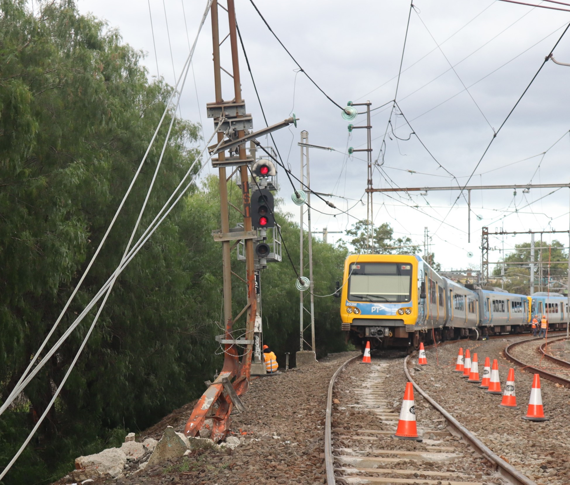
The derailed train collided with stanchions carrying overhead wires, resulting in substantial damage to the overhead infrastructure. About 100 metres of track and one passenger car were also significantly damaged.
There were no injuries to passengers or train crew in the incident.
The Office of the Chief Investigator is investigating the incident under the Transport Safety Investigation Act 2003 (Cth) under a collaboration agreement with the Australian Transport Safety Bureau.
A preliminary report, which details factual information established in the investigation’s early evidence collection phase, was released on 3 October 2025. See below.
The final report will be released at the conclusion of the investigation. However, should a critical safety issue be identified during the investigation, the ATSB and OCI will immediately notify relevant parties so safety action can be taken.
Last updated:
Preliminary report
Report release date: 03/10/2025
| This preliminary report details factual information established in the investigation’s early evidence collection phase, and has been prepared to provide timely information to the industry and public. Preliminary reports contain no analysis or findings, which will be detailed in the investigation’s final report. The information contained in this preliminary report is released in accordance with section 25 of the Transport Safety Investigation Act 2003. |
Summary video
The occurrence
Background
On 13 July 2025, a Metro Trains Melbourne (MTM)[1] train was providing passenger services on the Mernda and Hurstbridge lines on the metropolitan network in Melbourne, Victoria (Figure 1). The train comprised 2 coupled X’Trapolis 3-car sets.
Figure 1: Mernda and Hurstbridge lines
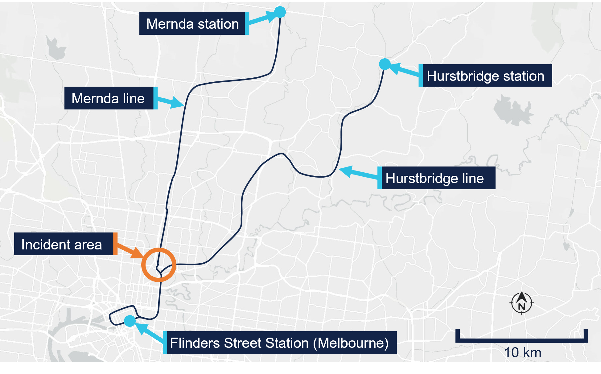
Source: Digital Atlas of Australia, annotated by the Office of the Chief Investigator (OCI)
That evening, it was scheduled to undertake a final round trip from Flinders Street Station (Melbourne) to Mernda and return. For this round trip, there were 2 drivers in the driving cab, the rostered driver and a principal driver.[2] The principal driver was in control of the train for this round trip as they were seeking to maintain familiarity with driving this route. The outbound journey from Melbourne to Mernda was uneventful, and the train arrived at Mernda station at about 2131.
The derailment
At about 2146, the train departed Mernda towards Melbourne as service TD1094, the final service of the evening before the line was to close for overnight maintenance. Initially the service proceeded as normal, stopping at all stations. At about 2225 the train departed Merri station and transited through a tight radius left curve before arriving at Rushall. It departed Rushall station at about 2227 travelling towards Clifton Hill (Figure 2).
Figure 2: Path of service TD1094 towards the High Street bridge
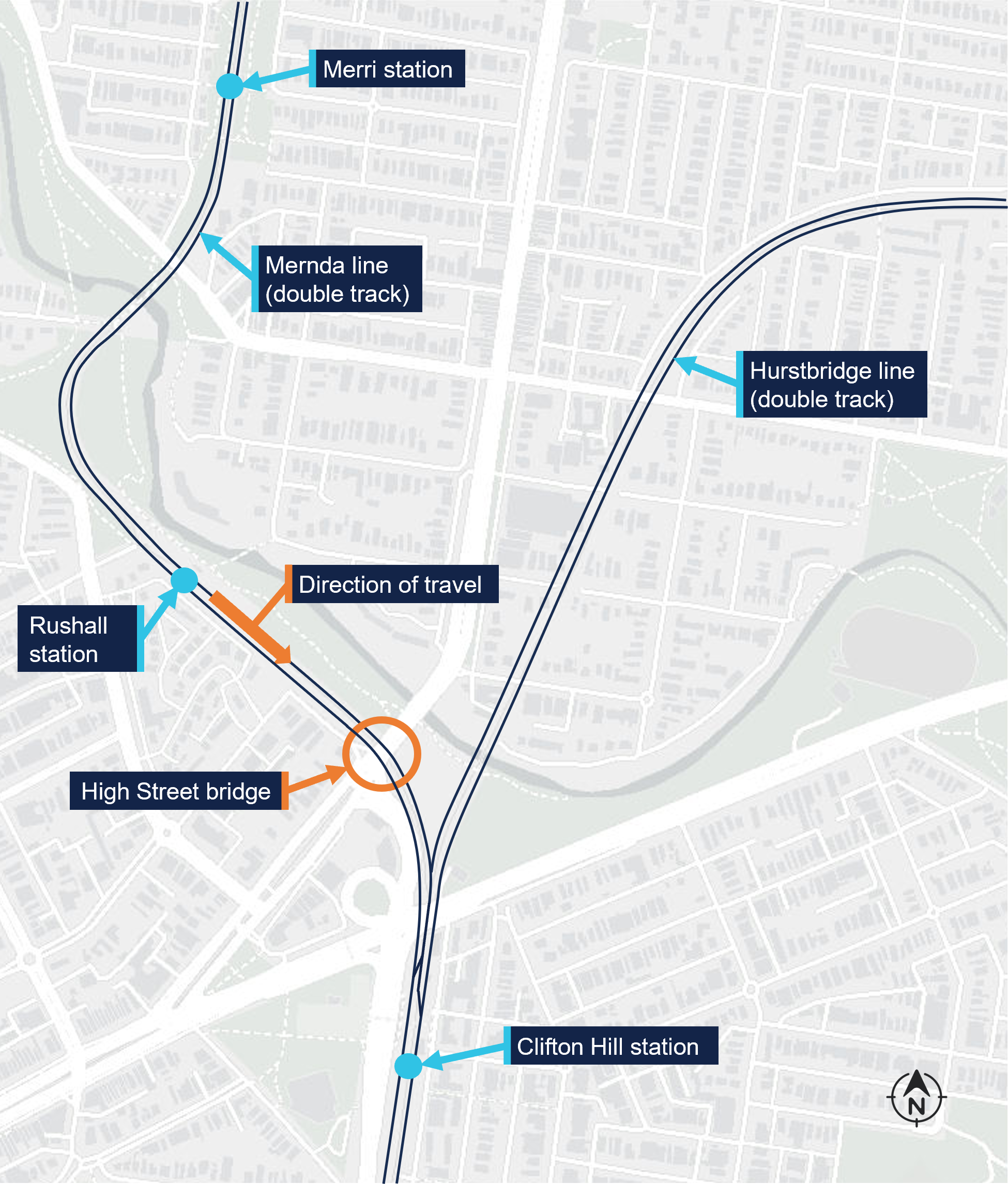
Overview of the incident area and the location of the High Street bridge. Source: Digital Atlas of Australia, annotated by OCI
After its departure from Rushall, the train initially accelerated to about 38 km/h. The driver then reduced the train’s speed in preparation for the right curve over the High Street bridge.[3] It was this driver’s normal practice to slow to about 30 km/h for this curve, which had a 40 km/h permitted speed. At about 2228 the train was proceeding through the curve at about 28 km/h when the leading wheelset of the first bogie of the 5th car derailed on the bridge (Figure 3). The left wheel of this wheelset had climbed over the left rail toward the outside of the right curve.
Figure 3: Location of derailment on the High Street bridge
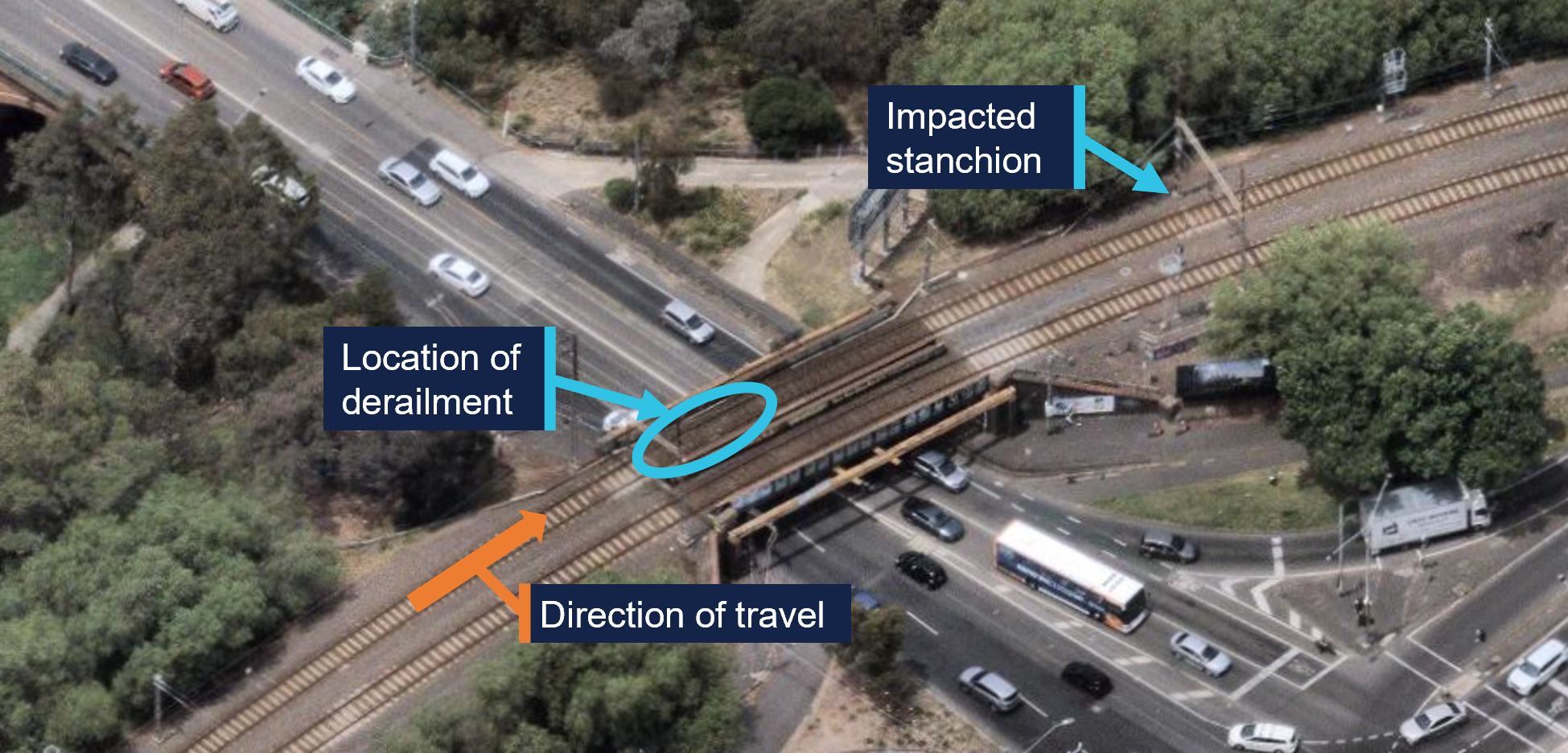
Source: Nearmap, annotated by OCI
As a result of the leading wheelset moving to the left, the right wheel dropped to the inside of the right rail. The train continued to cross the bridge with the derailed wheelset impacting rail fixtures and sleepers. Witness marks on sleepers were consistent with the initial derailment being a single axle (Figure 4).
Figure 4: Marks made on sleepers by the derailed wheels
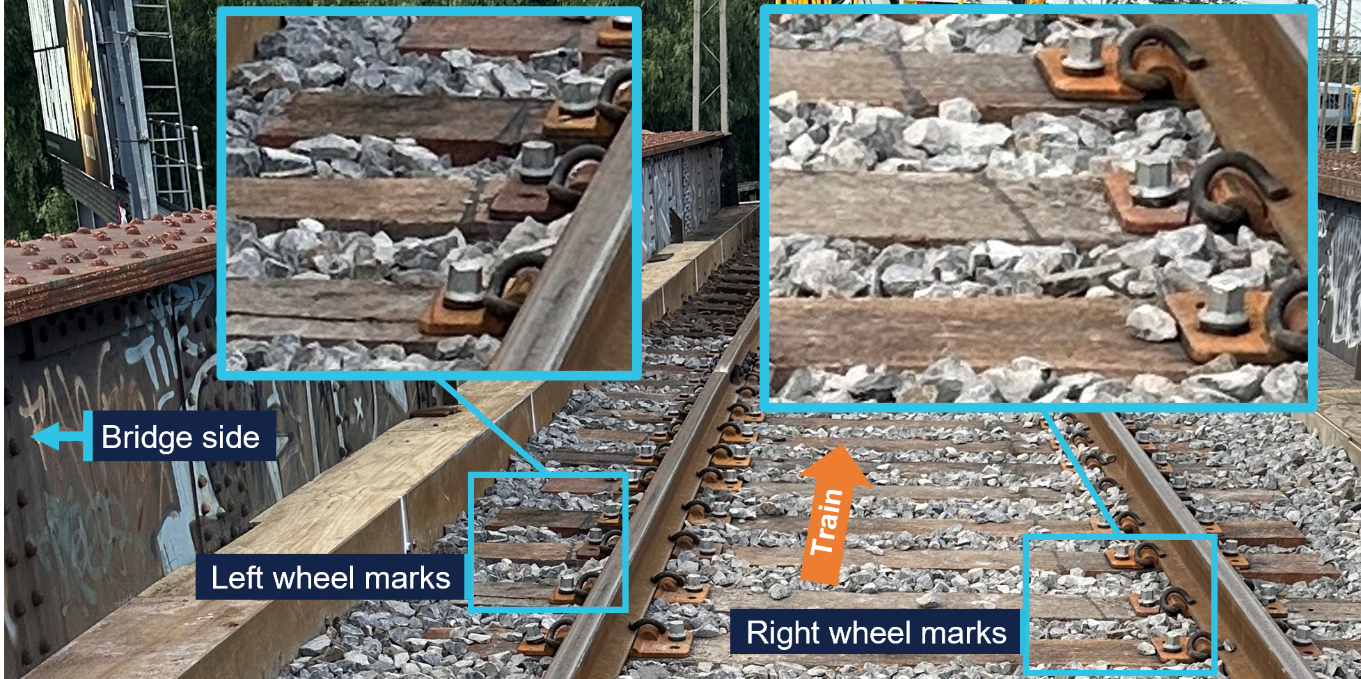
Source: OCI
Initially the derailed wheels moved along the sleepers in close proximity to the rails. However, once off the bridge deck, the wheel path began to move further to the left until the front of the car-body and the first bogie struck a stanchion, part of an overhead wiring gantry. The impact of the front left corner of the bogie with the stanchion further rotated the bogie in an anticlockwise direction,[4] derailing its trailing axle toward the inside of the right curve and pushing the leading end of the 5th car back towards the alignment of the track.
The stanchion was substantially damaged by the impact (refer to photo at top of page) which caused the overhead wire that supplied electrical power to trains to move and lose tension. This resulted in electrical arcing between the overhead wire and the train, most probably the pantograph[5] mounted on top of the 5th car.[6]
The 2 drivers were not initially aware of the derailment. Instead, they were alerted to an issue when they heard the electrical arcing and observed the overhead wire moving in front of the train. The principal driver made a brake application, and the train was brought to a stop after travelling about 120 m in a derailed state. The train’s carriages remained connected, and the internal passenger compartment spaces were not damaged. There were no injuries to passengers or train crew.
Incident response and passenger evacuation
At 2229, after stopping the train, the principal driver made a radio call to the MTM train control centre (Metrol) informing them of a probable issue with the overhead power. In discussion, the principal driver and the Metrol train controller agreed that the principal driver would investigate further. The principal driver moved to the rear of the leading 3‑car set before alighting on the train’s left side. The other driver remained in the leading driving cab at the controls of the train.
An operator at MTM’s electrical systems control centre (Electrol) had also identified a potential electrical issue in the area at about the same time. Circuit breakers at sub‑stations supplying power to the Rushall station area had tripped. At about 2230, in response, field staff were tasked to patrol the area and look for a fault. Shortly after, the Metrol train controller notified Electrol of the train’s loss of power. Responding to the updated information, Electrol arranged for the overhead power response team to attend the incident.
Meanwhile, the principal driver proceeded back along the outside of the train and observed that that the leading bogie of the 5th car was derailed. They recalled that they attempted to call Metrol by mobile phone to inform them of the derailment, however the line was busy. They then called one of MTM’s rail incident commanders (RIC)[7] and informed them of the derailment.
While the principal driver was inspecting the train from its left side, the driver who remained in the driving cab looked down the right side of the train and observed the trailing axle of the leading bogie on the 5th car derailed to that side (Figure 5). They reported the derailment to Metrol by train radio at 2239.
Figure 5: View of derailment from the front of the train
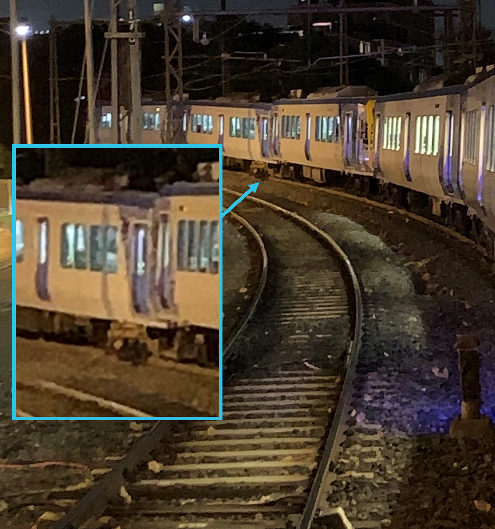
Source: Supplied
The RIC arrived at the incident at about 2306 and the overhead power response team arrived at about 2310. At about 2317 the RIC reported their observations to Metrol including the substantial damage to the overhead power stanchion.
There were about 30 passengers on board the train at the time of the derailment.[8] Passengers were moved into the leading car of each 3‑car set (the 1st and 4th cars) to wait until it was safe to detrain. While they waited, passengers in the 4th car repeatedly forced open the mid‑car passenger doors. However, passengers remained on board and did not self-detrain.
At about 0128 following confirmation from the overhead power response team that the site had been made safe, the RIC reported to Metrol that it was safe to detrain passengers. Passengers were detrained through the driving cab doors of the 3rd and 4th cars with no reported injuries during the evacuation.
Context
The train
Configuration
The train operating as TD1094 was a 6-car set made from 2 coupled X’Trapolis 3‑car sets.[9] The leading car‑set comprised cars 17M, 1309T and 18M and the trailing car‑set comprised cars 854M, 1627T and 853M (Figure 6).
Figure 6: Orientation of train for service TD1094
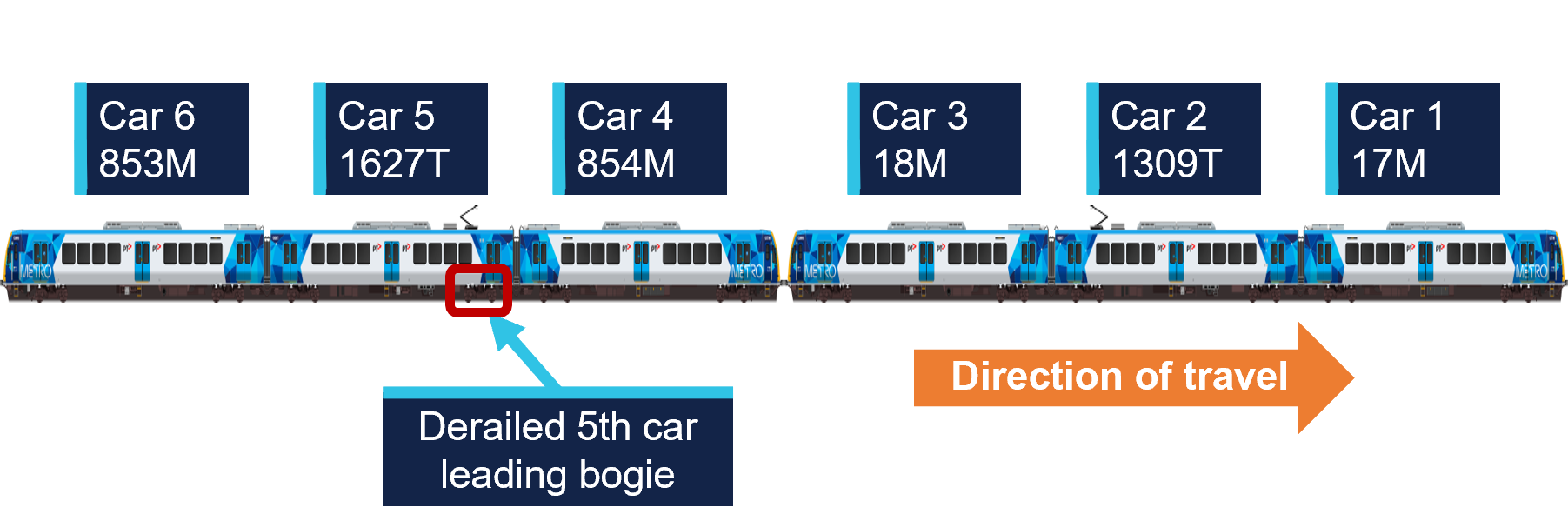
Source: MTM, modified and annotated by OCI
The motor (M) cars in each car-set incorporated a driving cab and traction motors. The trailer (T) cars were each fitted with a pantograph and associated power infrastructure that drew power from the overhead wire and distributed it to the traction motors on the motor cars. The trailer cars were not fitted with traction motors.
These car-sets had been operating together since 3 July 2025, including several services on the Mernda line up until 8 July. This train did not operate again on the Mernda line until 13 July, the day of the derailment. The derailment occurred on the fourth inbound Mernda to Melbourne trip the train had undertaken on the day.
Maintenance of derailed car-set
The most recent maintenance on the trailing 3‑car set 853M‑1627T‑854M[10] was completed on 6 June 2025. This maintenance included re‑profiling of all wheels on the 3 cars to the target (MP2) profile for the MTM passenger train fleet. At the time of the derailment, the wheels had travelled about 12,800 km since re‑profiling and measurements taken after the derailment showed that there had been little wear.
Inspection of the derailed car
Damage to the 5th car was consistent with the derailment sequence including impact damage to the leading left corner of the car‑body, bogie frame and suspension components (Figure 7). The impact with the stanchion also resulted in extreme rotation of the derailed bogie. This rotation damaged further suspension components and resulted in the rear left corner of the bogie frame impacting and piercing a battery box mounted to the underfloor of the car body. Rolling stock component testing and assessment is ongoing.
Figure 7: Impact damage to the car-body, bogie frame and suspension of the 5th car
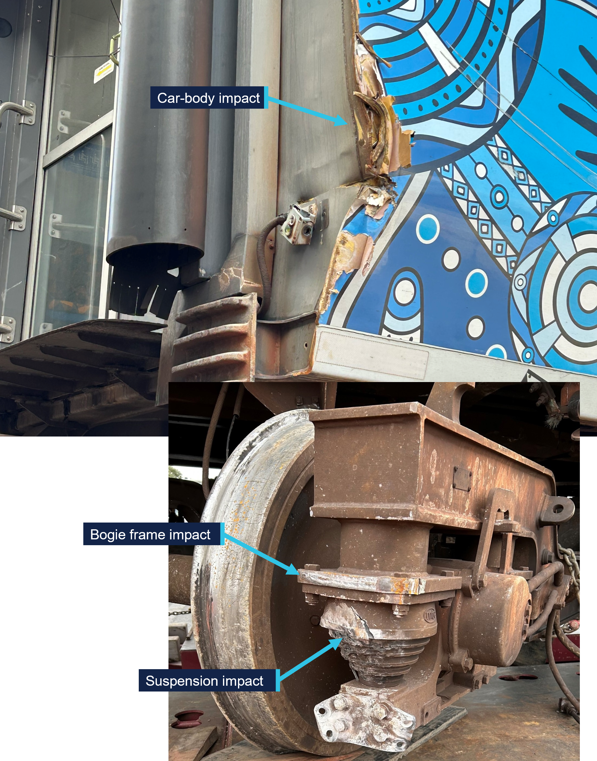
Source: OCI
Power supply
The Melbourne metropolitan rail system is an electrified network. Trains were supplied 1500 V direct current (DC) by an overhead wire system. The power was distributed to the network in sections by sub‑stations that transformed a 22 kV alternating current (AC) electricity supply to 1500 V DC. The stanchion that was impacted during the derailment was part of a gantry that carried both the 1500 V DC overhead wire and 22 kV AC conductors, both of which were damaged during the impact.
Track
Layout
The distance from the departure end of the Rushall station platform to the start of the High Street bridge was about 220 m.[11] There were 2 parallel tracks on the bridge and the train was on the track normally used for trains travelling toward Melbourne.
Approaching the High Street bridge from Rushall, the track was tangent (straight) and uphill before transitioning to a right curve that continued over the bridge and toward Clifton Hill. Track geometry measurements taken in May 2025 (prior to the derailment) indicated the tightest radius in the right curve was about 258 m. There was also a vertical curve through the location with the bridge on a crest. Track geometry was measured following the derailment and assessment is ongoing.
Maintenance
Track maintenance on the High Street bridge was undertaken on the nights of 8 and 9 July 2025. The maintenance works included replacing 27 timber sleepers and ballast along a length of about 14 m at the Rushall end of the bridge. Additionally, both rails were replaced across the full span of the bridge (about 25 m).
Flange climb derailment
Post-derailment track inspection identified witness marks consistent with a left wheel climbing the left rail near the Rushall end of the bridge. The point of flange climb was about 1.9 m from the start of the bridge and the wheel dropped to left of the rail after travelling about 3.4 m along the top of the rail (Figure 8).
Figure 8: Distances of left wheel derailment from the Rushall end of the bridge
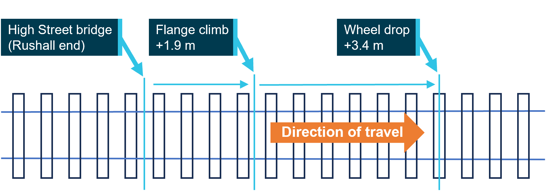
The derailment occurred on the High Street bridge. The approximate distances from the Rushall station end of the bridge are shown for key events. Source: OCI
The witness marks were consistent with the tip of the flange of the left leading wheel of the 5th car climbing onto the top of the rail from the inside (right) and running diagonally along the rail head before dropping to the left (Figure 9).
The presence of the wheel flange tip mark indicated that the initial derailment was by the action of flange climb. Flange climb occurs when lateral forces between the wheel and the rail exceed the capacity for vertical forces to restrain, either through excessive lateral force alone, or a combination of increased lateral force and reduced vertical force. The location of the derailment was in a tight radius curve. Therefore, the lateral force on the flange of the leading outside wheel was already high, as it was required to provide the force to turn through the curve.
Figure 9: Witness marks along the head of the left rail
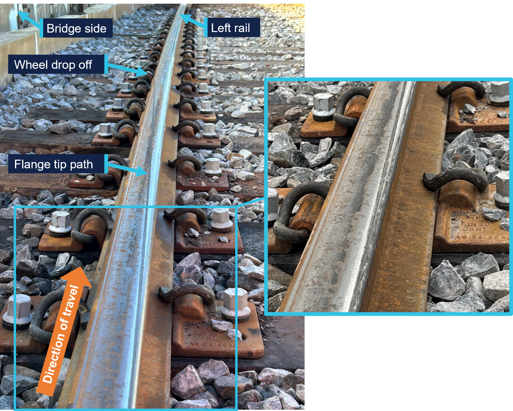
The figure shows the flange climb mark made by the tip of wheel flange looking in the train’s direction of travel. The inset shows additional detail along the rail gauge corner. Source: OCI
Further investigation
To date, the following activities have been undertaken:
- Inspections of the incident site
- Inspections of rolling stock
- Examination of track geometry and rail profile
- Examination of train recorded data
- Examination of maintenance records
- Review of recorded communications between involved parties
- Interviews with involved parties.
The investigation is continuing and will include further review and analysis of:
- Factors potentially related to the flange climb derailment including:
- Rolling stock wheel and suspension component condition
- Track condition including geometry and maintenance practices
- Wheel to rail contact conditions
- The emergency response to the derailment and overhead damage.
A final report will be released at the conclusion of the investigation. Should a critical safety issue be identified during the course of the investigation, relevant parties will be immediately notified so appropriate and timely safety action can be taken.
Rail safety investigations in VictoriaRail safety investigations in Victoria are conducted by the Office of the Chief Investigator (OCI) in accordance with a collaboration agreement with the ATSB. OCI is the operational office of the Chief Investigator, Transport Safety, a statutory position established in the Transport Integration Act 2010 (Vic) to provide independent, no-blame investigation of transport safety matters in Victoria. Under the collaboration agreement with the ATSB, OCI staff exercise powers and perform functions under the Transport Safety Investigation Act 2003 (Cth), and reports are approved for release under the TSI Act by the ATSB Commission. Purpose of safety investigationsThe objective of a safety investigation is to enhance transport safety. This is done through:
Investigations under the TSI Act do not apportion blame or provide a means for determining liability. At the same time, an investigation report must include factual material of sufficient weight to support the analysis and findings. Under the TSI Act investigations endeavour to balance the use of material that could imply adverse comment with the need to properly explain what happened, and why, in a fair and unbiased manner. TSI Act investigations are not for the purpose of taking administrative, regulatory or criminal action. About ATSB reportsATSB investigation reports are organised with regard to international standards or instruments, as applicable, and with ATSB procedures and guidelines. An explanation of terminology used in ATSB investigation reports is available here. This includes terms such as occurrence, contributing factor, other factor that increased risk, and safety issue. Publishing informationReleased in accordance with section 25 of the Transport Safety Investigation Act 2003 Published by: Australian Transport Safety Bureau © Commonwealth of Australia 2025 
Ownership of intellectual property rights in this publication Unless otherwise noted, copyright (and any other intellectual property rights, if any) in this report publication is owned by the Commonwealth of Australia. Creative Commons licence With the exception of the Commonwealth Coat of Arms, ATSB logo, and photos and graphics in which a third party holds copyright, this report is licensed under a Creative Commons Attribution 4.0 International licence. The CC BY 4.0 licence enables you to distribute, remix, adapt, and build upon our material in any medium or format, so long as attribution is given to the Australian Transport Safety Bureau. Copyright in material obtained from other agencies, private individuals or organisations, belongs to those agencies, individuals or organisations. Where you wish to use their material, you will need to contact them directly. |
[1] The franchisee and accredited rail transport operator of the Melbourne metropolitan rail network.
[2] At MTM, a principal driver is an experienced train driver who may provide advice and support to other drivers and conduct safety and competency training and assessment tasks. It is not unusual for principal drivers to request to drive a service when not rostered for other tasks, as was the case on this trip.
[3] The High Street bridge is sometimes also called Queens Parade bridge as the road changes name in close proximity.
[4] When viewed from above.
[5] A pantograph is an apparatus fixed to the roof of electric trains to draw power from the overhead supply.
[6] Available evidence did not indicate arcing between overhead wires and the body of the 5th car.
[7] A RIC was the MTM site representative responsible for coordinating site actions in response to an incident.
[8] Passenger numbers were not recorded. The estimate reported is based on CCTV vision of passengers exiting into the driving cab of the 3rd and 4th cars.
[9] The Alstom X’Trapolis 100 first entered service in Melbourne in 2002, initially operating on the (then named) Hillside Trains network which included the Mernda line.
[10] Car-set 853M-1627T-854M was in the first tranche of delivered sets.
[11] The start of the bridge was at about 7.065 track km. On the Melbourne metropolitan network, track kilometres (track km) are a measure of the distance along a track from Southern Cross Station in central Melbourne.
Occurrence summary
| Investigation number | RO-2025-005 |
|---|---|
| Occurrence date | 13/07/2025 |
| Occurrence time and timezone | 22:30 Australian Eastern Standard Time |
| Location | Clifton Hill |
| State | Victoria |
| Report release date | 03/10/2025 |
| Report status | Preliminary |
| Anticipated completion | Q4 2026 |
| Investigation level | Defined |
| Investigation type | Occurrence Investigation |
| Investigation phase | Final report: Drafting |
| Investigation status | Active |
| Mode of transport | Rail |
| Rail occurrence category | Derailment |
| Occurrence class | Serious Incident |
| Highest injury level | None |
Train details
| Train operator | Metro Trains Melbourne |
|---|---|
| Train number | TD1094 |
| Rail vehicle sector | Passenger - metropolitan |
| Departure point | Mernda station, Victoria |
| Destination | Flinders Street Station (Melbourne), Victoria |
| Train damage | Substantial |