Derailment of freight train 82P7 and subsequent collision with coal train 9F02, 3 km east of Marmor, Queensland, on 29 January 2023
Final report
Report release date: 30/06/2026
Investigation summary
What happened
On 29 January 2023, at about 1910 local time, Pacific National Pty Ltd freight train 82P7 was travelling west at about 100 km/h on the down line near Marmor, Queensland. As the train approached a level crossing, the axle of the leading wheelset on the third bogie of the sixth wagon fractured. Both wheels derailed into the centre of the track and travelled in the derailed condition over the points and crossings. Subsequently, the rear 8 wagons of the train separated and piled up over the level crossing. The front half of train 82P7 came to a stop around 1.3 km from the point of derailment.
Around the same time, train 9F02 was travelling in the up direction towards Marmor and passed the remaining signal between itself and train 82P7. The driver of train 9F02 observed the dust generated by the wreckage of train 82P7 and made an emergency brake application. This prevented train 9F02 from encountering the main wreckage of train 82P7. Nevertheless, train 9F02 collided with a container, still attached to the remaining front portion of train 82P7, that was fouling the up line. There were nil injuries to either train crew but both trains were substantially damaged.
What the ATSB found
The ATSB found that the derailment of train 82P7 and subsequent collision with train 9F02 was the result of a fractured axle. It was very likely that impact damage, sustained by the axle some time before the accident, initiated a fatigue crack that propagated until failure, resulting in the derailment.
The design of the fractured axle (NB) had a 154 mm diameter centre section. Axles conforming to this design presented a greater risk of failing as a result of a damage‑initiated fatigue crack compared with an alternate design used by Pacific National, which had a 165 mm diameter centre section.
The risk controls used by Pacific National to address the greater risk of failure posed by the NB axle design did not provide the best opportunity to ensure the removal of axle barrel damage capable of initiating a crack or to ensure axles with growing cracks were removed from service prior to failure. Despite this, it was not possible to establish if the damage that initiated the fatigue crack, or the growing fatigue crack, was present at the most recent wheelset overhaul.
The ATSB also found that Pacific National did not ensure its Asset and Infrastructure Services group, which was responsible for the management of rolling stock, performed risk management activities in accordance with the documented procedure. Specific areas where procedures were not followed related to the use of risk registers and risk management training. This was a missed opportunity to improve the group’s ability to systematically manage risks.
Lastly, the Association of American Railroads standard S-659 allowed blending repair of surface damage on axle barrels, with limitations to the number and total area of repairs. These limitations had been implemented as though applicable for each visit to an overhaul facility, rather than over the life of the axle, meaning that cumulative repairs over multiple overhaul visits were not being tracked. As a result, it was possible for the limits to be exceeded increasing the risk of axle failure.
What has been done as a result
Pacific National phased out all NB axles by 15 August 2024.
Pacific National’s operational and Health, Safety, Environment, and Sustainability risk register was redeveloped and a new consolidated register uploaded to a single system. Pacific National also held risk workshops to review and validate risk information. Furthermore, a central repository for all completed operational task-based risk assessments has been established providing a focus area to improve the way Pacific National reviews and monitors risk assessment actions and change management activities.
Pacific National's Health, Safety, Environment, and Sustainability management system for risk management has been updated with new governance documents and tools. To support the implementation of the new documents and tools, an e-learning module has been developed to step frontline leaders through the risk management framework.
Pacific National is also implementing an enhancement to its rolling stock database wheelset completion sheets. The enhancement includes a new field on the completion sheet that records the cumulative number of repairs completed on the axle. This will enable Pacific National and overhaulers to ensure limits are not exceeded. The enhancement was implemented on 29 January 2025.
Safety message
To ensure the safety of its operations, a rolling stock operator must eliminate or minimise risks to safety so far as is reasonably practicable. This is achieved through systematic risk management, a critical activity where risks are identified, assessed, eliminated, or controlled. An operator’s procedures codify the expected approach to risk management. Operators are required not to just have procedures in place, but to ensure they are followed in all areas of their operation. This can be achieved through formal training and review.
ONRSR expects ongoing monitoring and review of the identified risks and the adequacy of the control measures used to manage them through the use of risk registers. Risk registers ensure that there is a mechanism promoting re-evaluation of a risk where controls have been implemented to ensure the controls are effective.
Standards help industry improve safety, reduce costs, and increase productivity and efficiency. When adopting a standard, or incorporating elements of a standard in organisational procedures, organisations are reminded to verify that there are mechanisms in place to ensure that compliance can be achieved.
Summary video
The occurrence
Derailment of train 82P7
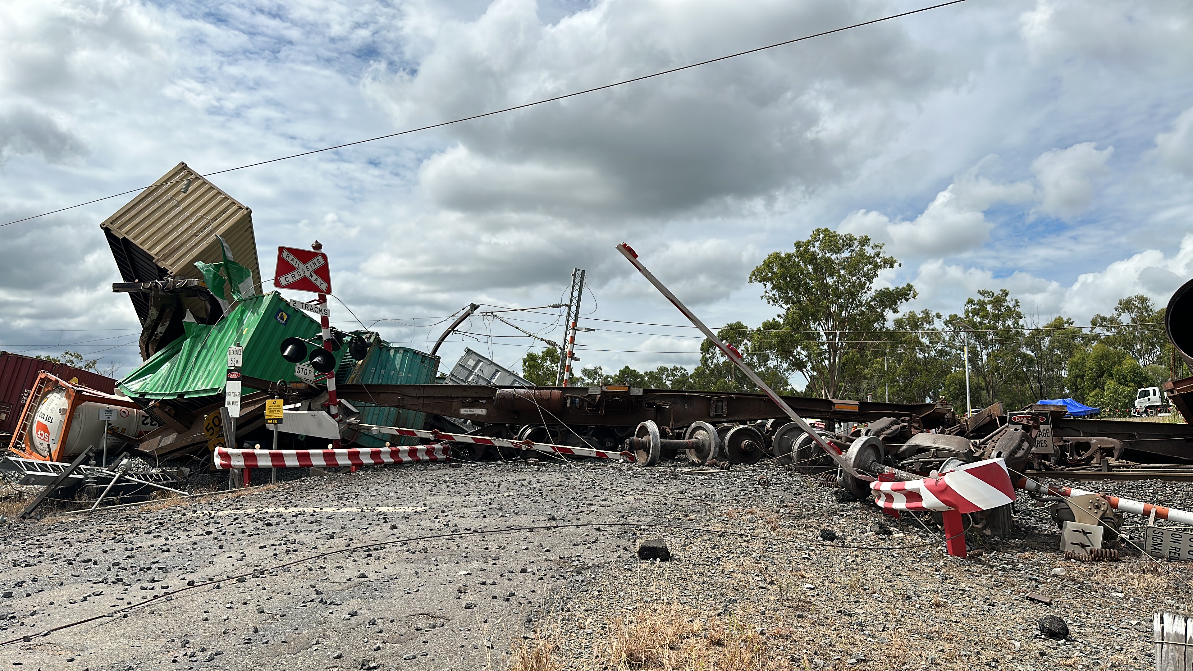
On 29 January 2023, at about 1910 local time, Pacific National Pty Ltd freight train 82P7 was travelling west on the Aurizon Network Pty Ltd network at about 100 km/h on the down line near Marmor, Queensland. At 1910:05, as the train approached the Bills Road level crossing, the rear 8 wagons separated from the train, which disconnected the brake pipe, resulting in application of the brakes. At around the same time, the driver, unaware of the separation, reported that the train did not respond as expected when the throttle was applied and they noted a slight drag. The driver stated they checked the locomotive mirrors, noticed sparks coming from the train, and made a brake application. The brake application by the driver was recorded 5 seconds after the brake pipe pressure started to drop following its disconnection. At 1910:29, as the train was slowing, the driver broadcast an emergency call over the ultra‑high frequency radio. After stopping at 1911:03, it was determined that the 8 rear wagons from train 82P7 had derailed, significantly damaging points, crossings, level crossing equipment, and overhead wiring stanchions (Figure 1).
Figure 1: Main wreckage site of train 82P7 at Bills Road level crossing
Source: ATSB
Collision with train 9F02
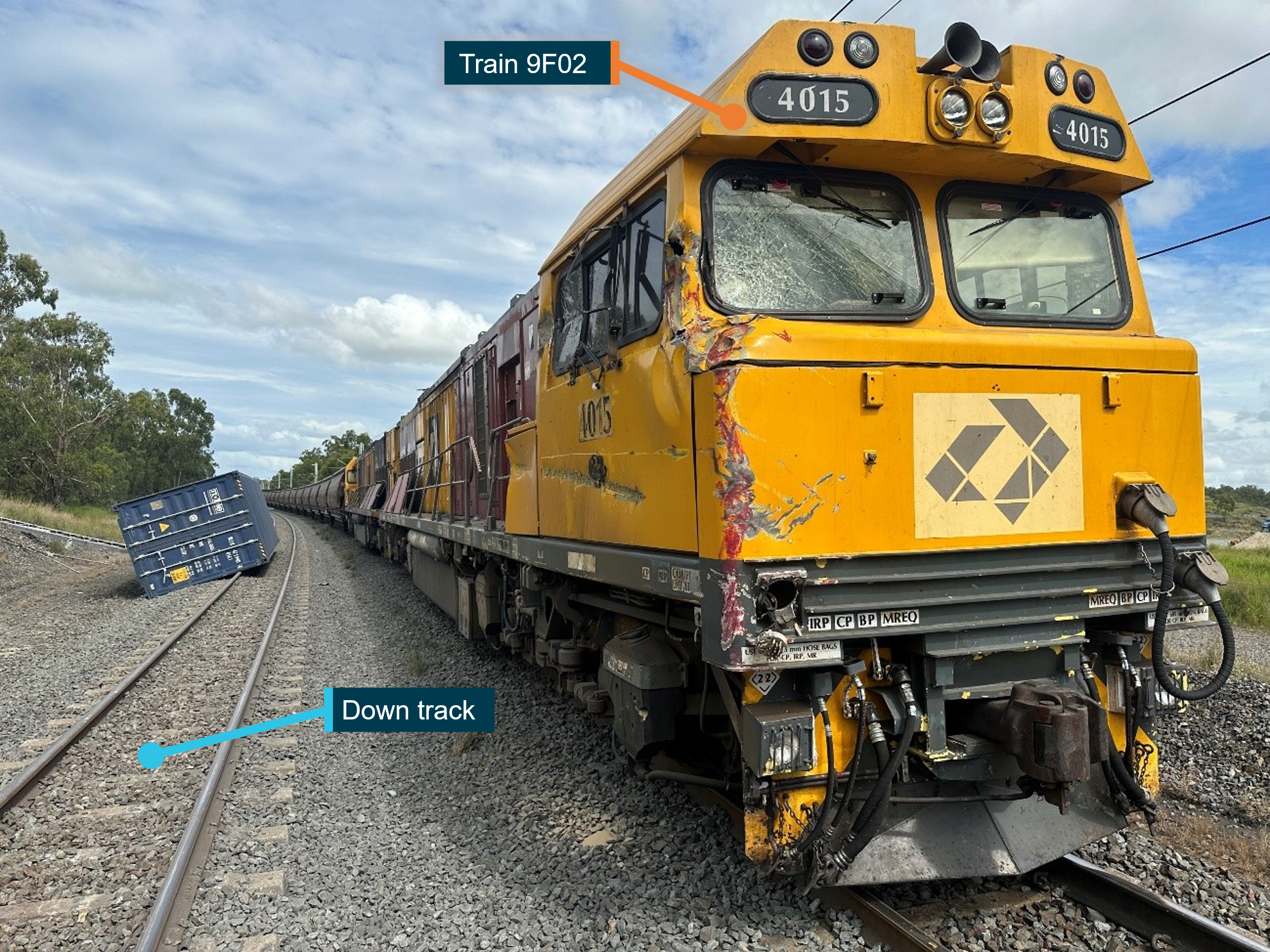
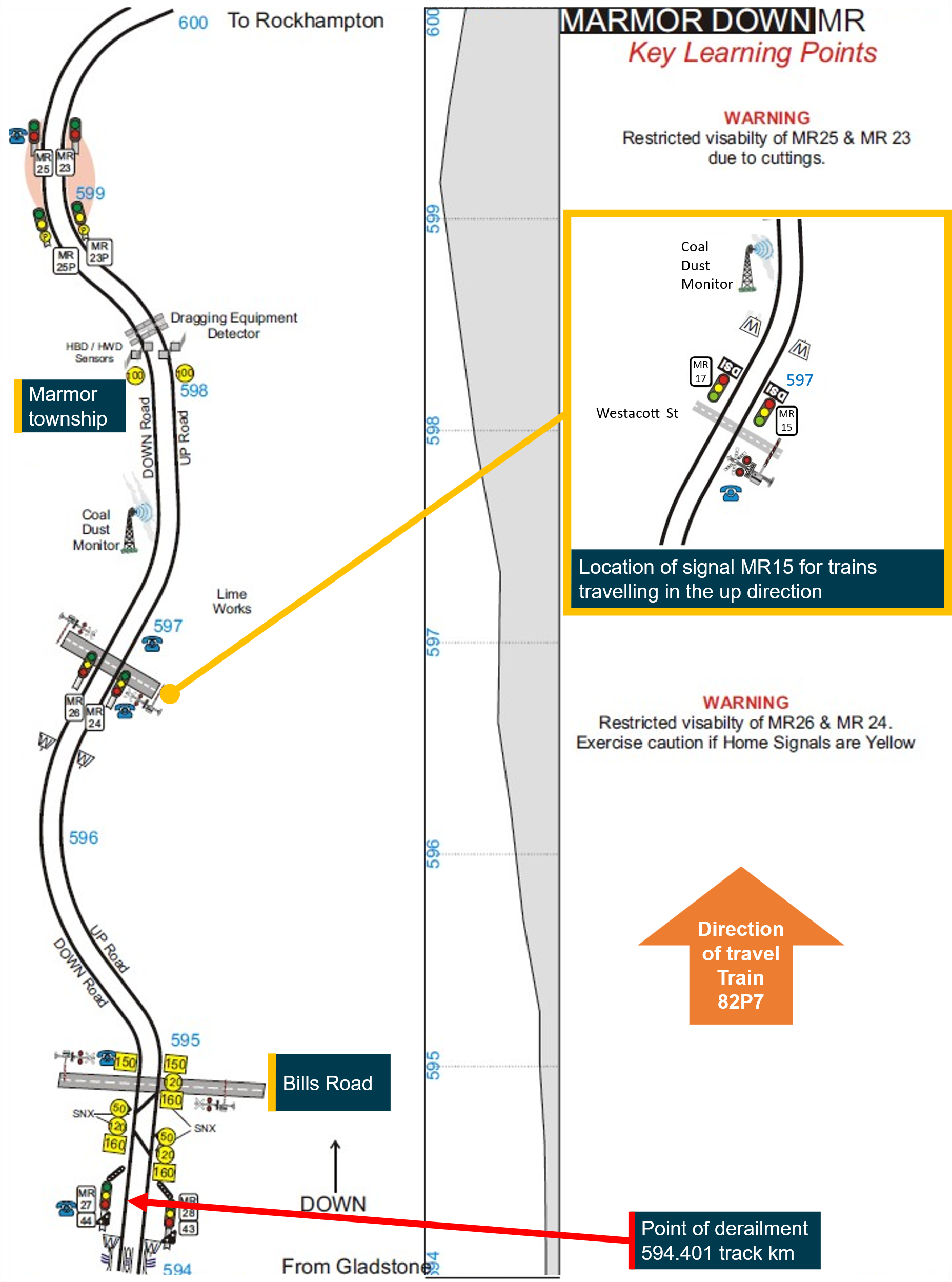
At about the same time as, or just prior to, the emergency call from train 82P7, the Aurizon network controller, located in Rockhampton, called Aurizon Operations Ltd coal train 9F02, which was travelling east on the up line, via radio regarding a loss of signalling detection at the points near the Bills Road level crossing. Train 9F02 had recently passed signal MR15, indicating a green proceed signal. This was the last signal for trains travelling in the up direction before the signals associated with the level crossing. Around this time, the crew of train 9F02 noticed a cloud of dust emanating from a train on the down line ahead. The driver of train 9F02 began to apply the emergency brake but train 9F02 collided with a displaced container still attached to a wagon of train 82P7, which was fouling the up line. Train 9F02 stopped adjacent to a different container (Figure 2). It did not reach the main wreckage of train 82P7, located near the Bills Road level crossing (Figure 3). Train 9F02 sustained significant impact damage to the driver’s side of the cab on the lead locomotive and along the side of the train.
Figure 2: Damage to leading locomotive of train 9F02
Source: ATSB
Figure 3: Schematic of the track section near Marmor, Queensland
Source: Aurizon Network Pty Ltd, annotated by the ATSB
Onsite inspection
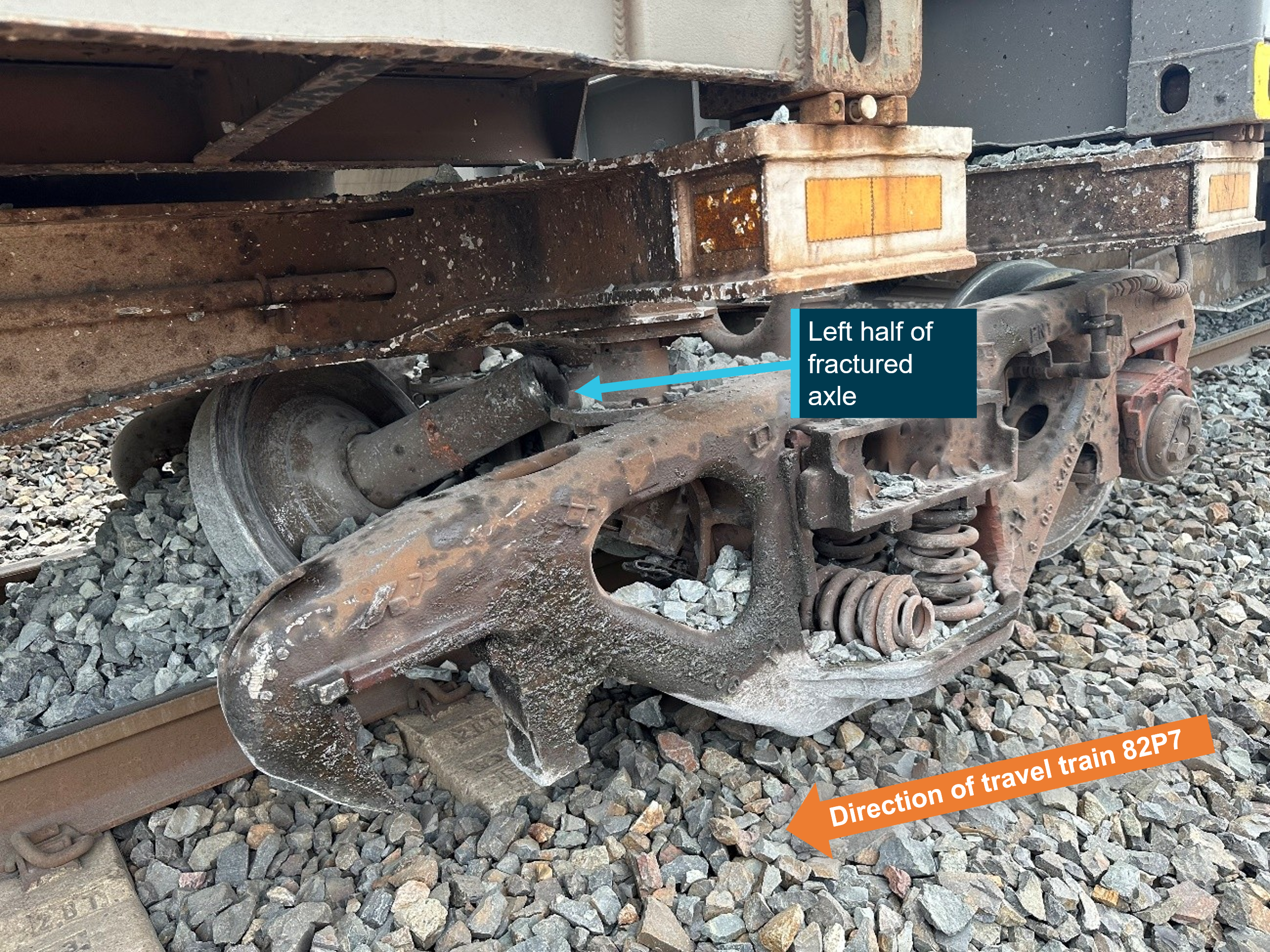
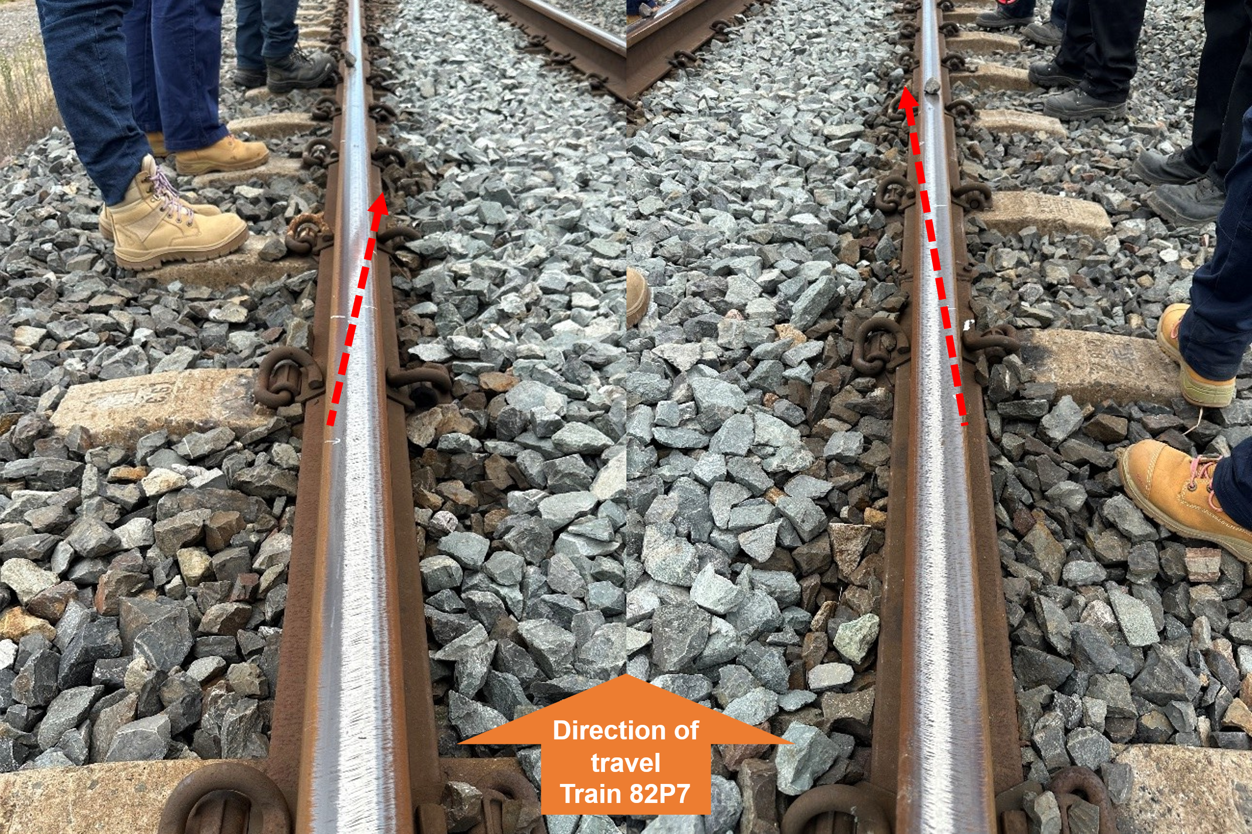
During onsite inspections, the ATSB found an axle from the sixth wagon (RNCY137-T) on train 82P7 had fractured (Figure 4). This evidence correlated with rail-wheel field‑side1 marks found on the rail head (Figure 5), identified as a point of derailment, situated before the signalling infrastructure and the points (Figure 3). The marks commenced on the field-side of the rail head and ran inwards towards the rail gauge face between both rails. There was no other evidence of derailment found on the approach to the point of derailment.
Figure 4: Damaged bogie of RNCY137-T showing half of the fractured axle
Source: ATSB
Figure 5: Wheel marks identified on the left and right rail head at the point of derailment
Source: ATSB
Context
Track information
The bi-directional duplicated narrow-gauge track2 between Callemondah and Rocklands, Queensland, on the Blackwater system consisted of 60 kg/m rail, fixed to concrete sleepers with resilient fasteners. The track section was electrified with overhead line equipment. The rail infrastructure manager was Aurizon Network Pty Ltd, who operated the section by remote control signalling, with train movements controlled from Rockhampton. In the up direction, approaching the Marmor township, the track was a heavy descending grade towards signal MR15.
Train and crew information
Train 82P7
General
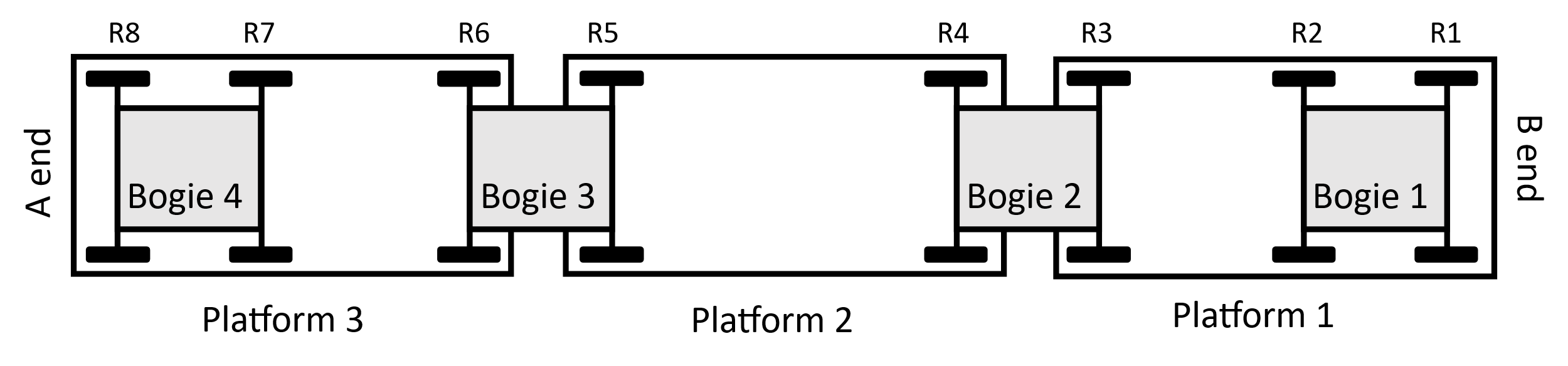
Train 82P7 was a superfreight type train operated by Pacific National, which originated at Moolabin yard in Brisbane, and was destined for Townsville terminal. The train consisted of a leading Pacific National locomotive (PN10) and 16 intermodal freight wagons. Each wagon was a ‘triple-pack’ wagon, comprised of 3 platforms and 4 bogies (Figure 6). Each bogie was fitted with 2 wheelsets.3 The total length of the train was 685.32 m with a gross mass of 1,366.397 tonnes. Train 82P7 was crewed by a single traction-qualified and route-competent locomotive driver.
Figure 6: Schematic of a triple-pack wagon on train 82P7
Source: ATSB
Pacific National axle designs
Pacific National had 4 different axle designs traveling on narrow-gauge tracks, 2 types each for ‘K’ class and ‘L’ class axles.4 Narrow-gauge ‘L’ class axles were relevant to this accident and included:
- ‘full’ axle-barrel-diameter axles, designated 7L7N:
The radial dimensions of these axles broadly corresponded to the dimensions of the Association of American Railroads (AAR) ‘L’ class raised wheel seat roller bearing axles for freight cars (AAR, 2016). The longitudinal dimensions differed, as the 7L7N axle design was suited to narrow-gauge track, while the AAR ‘L’ class design was applicable to standard-gauge track.
The 7L7NB design (‘NB’ axle), was designed in 2004, for carrying 20‑tonne axle loads. The NB axle had a reduced barrel diameter as compared with the 7L7N axle design.
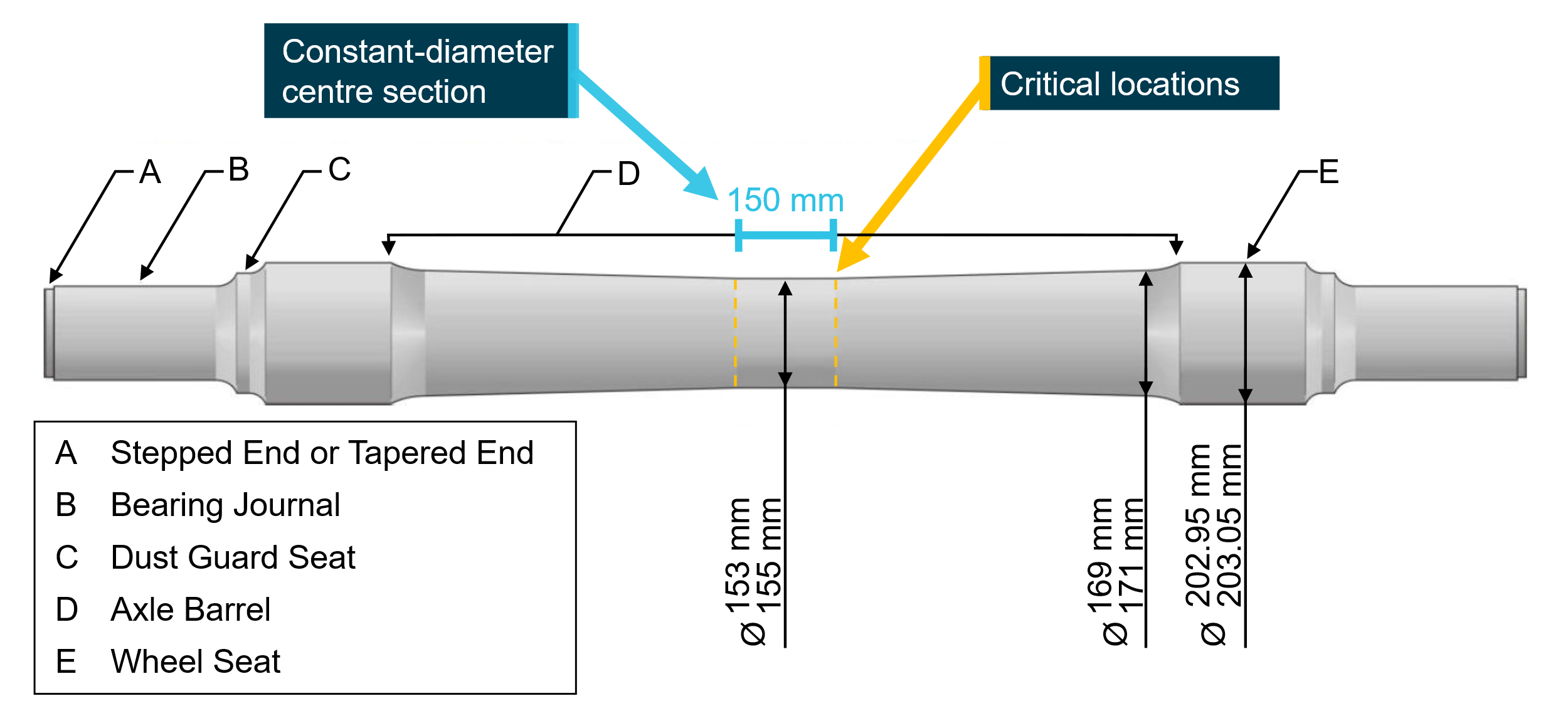
The design drawing for the NB axle (Figure 7), listed the diameter of the centre section of the axle as 154 ± 1 mm. This constant-diameter centre section was 150 mm long. The axle then tapered out to a diameter of 170 ± 1 mm over 366 mm, followed by a radius to transition to the wheel seat, which had a diameter of 203 + 0.05 mm (Figure 7 ‘E’). The total axle length was 1,816 mm. In contrast, the 7L7N axle had a greater diameter of 165 ± 1 mm for a 152 mm long constant‑diameter centre section, tapering out to 181 ± 1 mm near the wheel seat. The critical location of the NB axle barrel, where the margin of safety6 was smallest, was located at the transition between the constant‑diameter centre section and the taper.
Figure 7: Schematic of 7L7NB (NB) axle
Source: Pacific National, annotated by the ATSB
Train 9F02
Train 9F02 was a loaded Aurizon Operations Ltd coal train, originating at Kabra and destined for Callemondah. This train consisted of 2 leading locomotives, 2 remote locomotives, and 100 wagons. The train was 1,586 m long and 10,452 tonnes. Train 9F02 was crewed by 2 traction-qualified and route-competent locomotive drivers.
Recorded information
Data from the locomotive event recorders including time, speed, control positions, and the condition of various locomotive system parameters, was obtained from train 82P7 (both leading locomotives) and train 9F02. While rearward facing footage from one of the remote locomotives of train 9F02 was available, forward-facing footage from the lead locomotive was unavailable as the unit was not functional at the time of the accident. There was no evidence that train speed, handling, or operational performance contributed to the derailment. Voice recordings of the rail network operations to train communications were also provided.
A record of the universal traffic control system7 was obtained. The derailment likely occurred at 1910:02.3, based on the first recorded indication of an issue at 1910:12.3 when points near Bills Road lost detection, the location of those points, the location of the derailment markings, and the recorded speed of train 82P7.
The universal traffic control system also recorded the status of signal MR15, the last signal for train 9F02 before it encountered the wreckage of train 82P7. When passed by train 9F02 at 1910:00, signal MR15 indicated a green proceed signal. Two seconds later, following the passage of train 9F02, the signal restored to a red (stop) indication, as designed. Figure 8 shows the locations of both trains at the time when MR15 restored to a red indication.
Figure 8: Location of train 82P7 and train 9F02 when signal MR15 restored to red
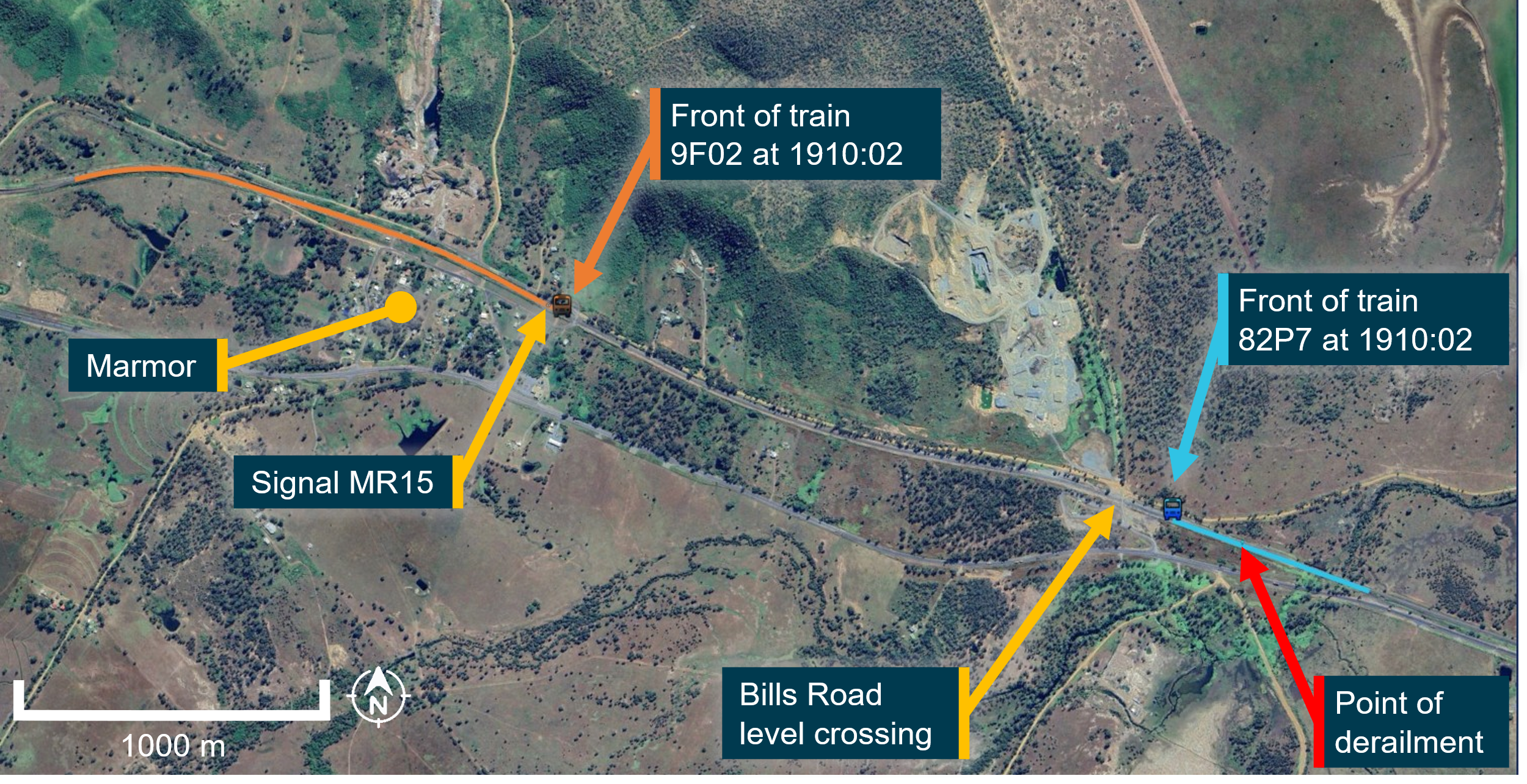
The length of the blue and orange lines indicates the full length of train 82P7 and train 9F02, respectively. Source: Google Earth, annotated by the ATSB
Accident site information
The accident site extended over 2.5 km from the point of derailment, around 400 m east of the Bills Road level crossing, to the trailing end of train 9F02 (Figure 9). The ATSB’s onsite examination identified the point of derailment to be at 594.401 track km8 (Figure 3). For the Raglan to Marmor section of track, no relevant track faults were identified during the inspection following the accident. Furthermore, the track cant9 and gauge measurements were within specification.
Figure 9: Overview of accident site
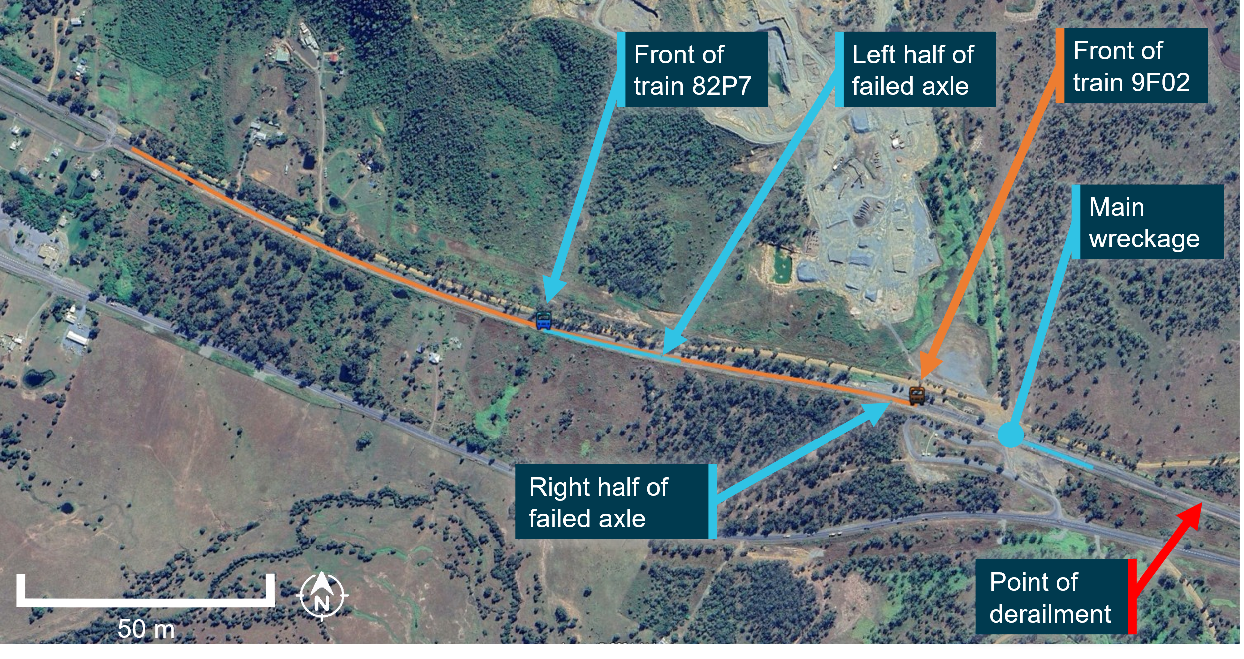
The length of the blue and orange lines indicates the full length of train 82P7 and train 9F02, respectively. At this time train 82P7 had separated into 2 sections represented by the 2 separate blue lines. Source: Google Earth, annotated by the ATSB
The track infrastructure sustained extensive damage from 594.401 track km to 595.510 track km, including damage to the points, level crossing equipment, and overhead line equipment. The main wreckage site (Figure 1), including the derailed rear 8 wagons of train 82P7, was located near the Bills Road level crossing at 596.710 track km.
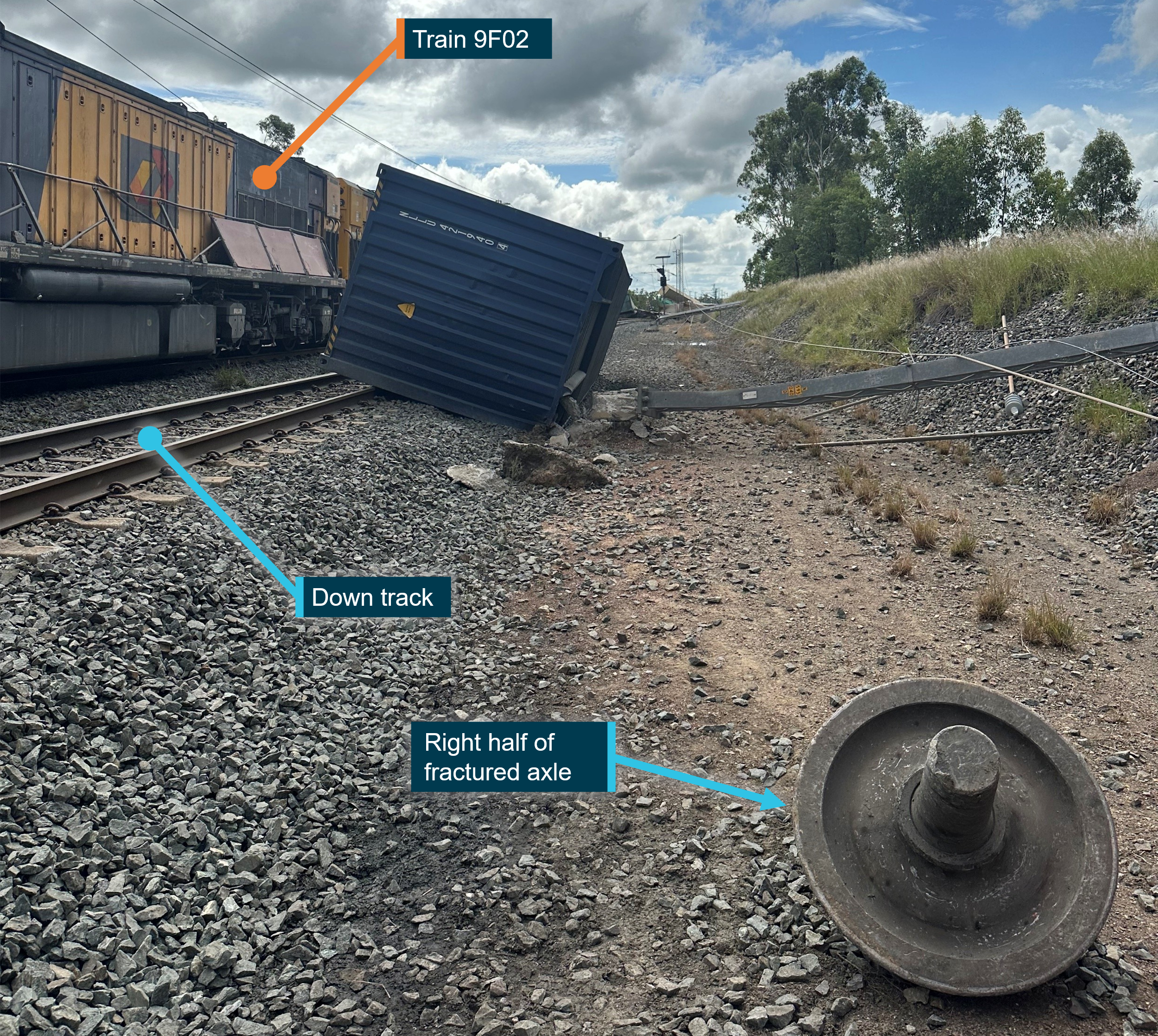
Train 9F02 came to a stop at 594.995 track km, shortly beyond a stationary container fouling the down line (Figure 2). Damage was sustained by both leading locomotives and the first 29 wagons of train 9F02. Also located in this area, off the tracks, was the right10 half of the fractured axle from train 82P7 (Figure 10).
Figure 10: Location of right half of fractured axle from train 82P7
Source: ATSB
The locomotive and leading wagons of train 82P7 had come to rest at 595.755 track km, about 1,300 m from the point of derailment. The left half of the fractured axle was observed within the 3rd bogie, connecting platform 2 and 3 of wagon RNCY137‑T, the 6th wagon in train 82P7 (Figure 4). This bogie and both halves of the fractured axle were taken for further examination.
Test and research
Examination of the fractured axle
The recovered fractured axle was identified as an NB axle with serial number 7L7NB4726. This was the leading axle on the 3rd bogie of the 6th wagon behind the locomotive (axle labelled R5 in Figure 6). Pacific National completed a post‑derailment inspection of the fractured axle, the sibling axle, and the bogie, which was observed by the ATSB. While the wheels and bogie were significantly damaged from the derailment, no pre‑existing concerns were identified with these components, other than the axle fracture. Paint had eroded from the surface of the barrel of both the fractured axle and its sibling axle.
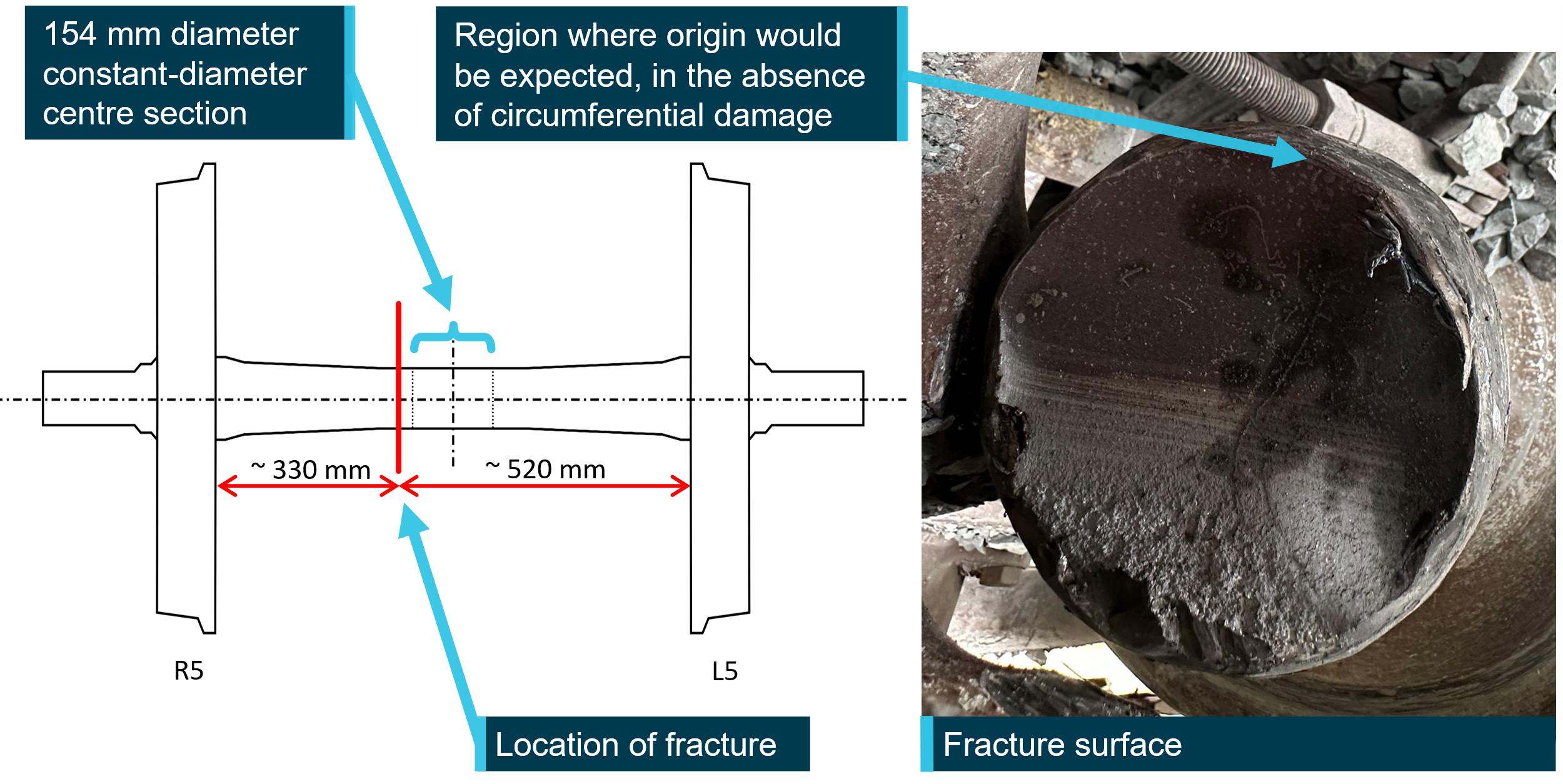
The axle had fractured around 95 mm to the right of the centreline (Figure 11). About 200 mm of axle material, including both sides of the fracture surface, was sectioned from the axle and examined at the ATSB technical facility in Canberra, Australian Capital Territory. The fracture surface exhibited progression marks,11 originating at a location on the circumference of the axle, consistent with fatigue fracture resulting from rotational bending. The indications of fatigue crack growth extended over around 60% of the axle cross-section, with a relatively small area of overstress failure, indicating low nominal stresses.12 Around 50% of the fracture surface exhibited surface oxidation producing a darker appearance. The circumference of the fracture surface was extensively damaged, such that it was not possible to identify a crack initiating feature.
The surface condition of the retained axle sections exhibited derailment damage in the form of scuffs and surface damage. The barrel surface was inspected for additional surface breaking cracks using magnetic particle inspection13 at the ATSB facility. There were no indications of additional cracks on the retained sections of the axle. Analysis of the axle material microstructure, hardness, and elemental composition found that the material was consistent with specification.
Figure 11: Failure location and fracture surface appearance of fractured axle
Source: ATSB
History of the fractured axle
The subject axle was manufactured in October 2004 by the Commonwealth Steel Company, also known as Comsteel. The axle underwent a bearing turn14 on 5 September 2013, a wheel disc was replaced on 17 March 2015, and the axle underwent another bearing turn on 5 September 2018. These rolling stock maintenance events occurred at an approved wheelset overhaul facility (overhauler), where the condition of the axle barrel would have been inspected.
Following the failure of a Pacific National axle in December 2019 (see Previous NB axle failure due to fatigue), Pacific National commenced a program of axle inspections, which included magnetic particle inspection of all NB axles on lower-duty wagons. Lower-duty wagons were intermodal freight wagons operated on the Queensland North Coast line with variable loading up to a maximum axle load of 20 tonnes. There was no record of magnetic particle inspection performed on the subject axle between the commencement of the program and 23 August 2021, when Pacific National reported that the program was completed.
On 11 October 2021, the axle was involved in a derailment while fitted to a lower-duty wagon (RNCY147‑E). The derailment occurred at low speed in a yard during the assembly/shunting of a train as it travelled over points. As specified in Pacific National procedures, the wheelsets involved in the derailment were removed and sent to an overhauler. The ‘why done description’ in Pacific National’s rolling stock database (Maximo) for this work order was ‘Derailment Damage’. On 9 December 2021, a Pacific National Wheelset Production Sheet15 checklist was populated for the axle. The overhauler selected ‘No Defects’ in the ‘Inspect & Repair on Axle Barrel Defects’ section and ‘Not Required’ in the ‘MPI [magnetic particle inspection] Completed on Repairs’ section. Nevertheless, the axle was subjected to magnetic particle inspection in accordance with the relevant Pacific National procedure; the finding was ‘No Cracking Found’.
On 7 January 2022, the axle was fitted as the 5th wheelset on lower-duty wagon RNCY137-T, the wagon it was fitted to at the time of this accident. Prior to the installation of the subject axle, the axles fitted to wagon RNCY137‑T were visually inspected, as per Rolling Stock Notice16 E 20‑004V2, on 22 April 2021 and underwent an ‘A’ Inspection (see Scheduled inspections) on the following day, with no issues reported.
The wagon meter reading, which indicated the total kilometres travelled, for wagon RNCY137‑T, now fitted with the subject axle, on 12 January 2022 was 3,260,009 km. On 26 April 2022, wagon RNCY137‑T underwent a ‘P’ inspection (see Scheduled inspections). The 2 axle‑related line items on the ‘P’ inspection checklist were ticked as completed, indicating no issues were identified with any of the 8 wheelsets fitted to the wagon. As of 28 January 2023, the meter reading for wagon RNCY137‑T was 3,451,133 km. The axle fractured the next day, on 29 January 2023, this was around 15 months after the yard derailment.
Wayside monitoring relating to the fractured axle
While the section of track where train 82P7 derailed was managed by Aurizon Network Pty Ltd, the train also travelled on track managed by Queensland Rail. Wayside monitoring equipment, located along Queensland Rail managed track between Moolabin yard and Gladstone, recorded parameters including train speed, wagon tonnage, bogie tonnage, axle tonnage, wagon side-to-side imbalance, wagon end-to-end imbalance, wheel impact loads, and bearing and wheel temperatures. The system did not generate any reports in response to the passage of train 82P7 on the accident journey. Train 82P7 did not travel over any wayside monitoring systems between Gladstone and Marmor, the region of track managed by Aurizon Network Pty Ltd. Therefore, a review of data sourced from wayside monitoring equipment for the accident journey did not reveal a condition with wagon RNCY137‑T that contributed to the axle failure, or subsequent derailment.
In the year prior to the axle failure, the passage of wagon RNCY137‑T triggered weighbridge17 alarms on the following 5 occasions. The subject axle, number 5 on bogie 3, is accentuated in bold:
- 1 May 2022 – wagon load was 133.83 tonne, bogie 3 exceeded 40‑tonne limit by 0.36 tonne, axle 5 exceeded 20‑tonne limit by 0.52 tonne.
- 15 July 2022 – wagon load was 109.60 tonne, bogie 2 exceeded 40‑tonne limit by 0.55 tonne, axle 3 exceeded 20‑tonne limit by 0.28 tonne, axle 4 exceeded 20‑tonne limit by 0.28 tonne.
- 1 September 2022 – wagon load was 100.21 tonne, bogie 3 exceeded 40‑tonne limit by 2.38 tonne, axle 5 exceeded 20‑tonne limit by 1.28 tonne, axle 6 exceeded 20‑tonne limit by 1.10 tonne.
- 28 September 2022 – wagon load was 142.27 tonne, axle 5 exceeded 20‑tonne limit by 0.20 tonne.
- 29 September 2022 – wagon load was 145.10 tonne, bogie 2 exceeded 40‑tonne limit by 0.16 tonne, axle 4 exceeded 20‑tonne limit by 0.41 tonne, bogie 3 exceeded 40‑tonne limit by 0.20 tonne, axle 5 exceeded 20‑tonne limit by 0.02 tonne, axle 6 exceeded 20‑tonne limit by 0.17 tonne.
The recorded wagon load on the alarm reports appeared to be the sum of the loads recorded for all 8 axles fitted to the wagon and on none of the 5 occasions was the whole wagon load more than the maximum allowable limit of 160 tonnes. Pacific National’s records for the same period found that the largest loading recorded for the wagon was 142 tonnes. That is, there was no record of the wagon being loaded above the maximum allowable limit. When asked about the axle loading alarms, Pacific National stated that ‘isolated events of overload’ should not be damaging to the axles given the margin of safety in the design.
Axle barrel fatigue prevention
General approach
Engineering structures and components are generally designed such that applied loads do not produce local stress levels that result in plastic deformation or failure, that is, the stresses are below the elastic limit of the material. Nevertheless, components, including steel railway axles, subject to cyclic loads may eventually fail even when the stress does not exceed the elastic limit by the phenomena known as ‘fatigue’.
Fatigue is the process of cumulative damage resulting from repeated fluctuating loads. The accumulated damage results in initiation and subsequent propagation of a crack, or cracks. Railway axles are a safety‑critical component exposed to a high number of loading cycles during a service life that can exceed 30 years (Lunden and others, 2009, June 22-25). Each revolution of the wheelset is considered a loading cycle and railway axles were among the first train components to give rise to fatigue problems (British Standards Institute, 2009).
Preventing and managing fatigue in axles can be achieved through the following means:
- Limiting the stress in the component:
A concept in engineering design is ‘fatigue limit’. The fatigue limit is the maximum stress amplitude range that a material can withstand over an (in theory) infinite number of cycles without failure. In the context of rail axles, if the cyclic stresses applied to an undamaged axle are below a permissible value, usually defined in a standard, then it would be expected that the axle should achieve its design lifetime before a fatigue crack would initiate. A safety margin is typically built into the design, by sizing the axle appropriately.
- Management of stress concentrators:
Even when a component is designed such that the applied cyclic loads do not produce stresses that exceed the fatigue limit of the material, a fatigue crack can initiate. This will occur at a stress concentrating feature. Lunden and others (2009, June 22-25) stated that the fatigue strength of an axle may be reduced by material defects and by corrosion and surface damage, for example, from flying ballast. When damage is present on an axle barrel it creates a local region of higher stress where the fatigue limit of the material can be exceeded, such that, given sufficient cycles a fatigue crack will initiate. The more severe the stress concentrator, the less cycles before crack initiation. To prevent cracks initiating, axle barrels can be inspected for stress concentrating ‘marks’ at regular intervals. Once identified, these marks can be ‘blended’, a process where material is removed such that the smooth contour of the axle is restored. While the load-bearing cross‑sectional area of the axle is reduced by this process, there is usually a safety margin within the design allowing for some section reduction without leading to stresses exceeding the fatigue limit. In most circumstances following blending, a non‑destructive crack detection test, for example, magnetic particle inspection, is performed on the blended area to ensure that an unacceptable crack has not already initiated from the now‑removed stress concentrator.
- Removal of cracked axles:
Not all ‘marks’ with the potential to initiate a fatigue crack will be identified and removed prior to a fatigue crack initiating. Accordingly, it is prudent to regularly inspect axles for growing cracks through non‑destructive means. Most frequently, the inspection interval is defined as the distance that can be safely travelled between 2 crack detection tests (Beretta and others, 2004). This interval is half the propagation life (Zerbst and others, 2005), which is the number of loading cycles between an initial crack size, frequently selected based on the probability of its detection, and the critical crack size, where failure is imminent. This lifetime, for a particular axle design, may have been established through industry experience or through engineering evaluation using finite element analysis.18 Inspection intervals smaller than half propagation life can be selected, such that there would be a second chance to detect a growing crack, should it be missed at the first inspection opportunity (Zerbst and others, 2005).
Fatigue crack prevention at Pacific National
Introduction
To ensure axles were not operated at loads where the fatigue limit of the axle barrel material was exceeded, the axles used by Pacific National were designed to meet accepted international standards. Furthermore, axles were subjected to inspection and maintenance programs to manage the risk of failure and ensure safe operation. These inspection programs involved sequences of scheduled inspections, at regular intervals, with differing scope, ranging from visual-only to comprehensive axle inspection and overhaul.
Overhaul process
Pacific National stated that the average kilometres travelled by a wheelset between visits to an overhaul facility was around 500,000 km. Wheelsets were sent to an overhauler for numerous reasons including, but not limited to:
- excessive wheel wear, for example, an excessively thin flange
- wheel damage, for example, a flat spot identified on a wheel
- bearing inspection
- the axle had been involved in a derailment
- the axle had been in-service for the maximum allowed range (km) specific to axle type and required magnetic particle inspection
- barrel damage had been identified during visual inspection
- planned changeout.
Pacific National used a ‘WHY_MADE_CODE’ in its rolling stock management database to indicate the reason a wheelset would be sent to an overhaul facility. In the 10 years prior to 2023, there were 9,005 entries where axles were assigned a WHY_MADE_CODE. A total of 34 unique codes were applied. Code 55, which corresponded to the description ‘Axle damaged between wheels’, was used on 5 occasions.
When a wheelset entered an overhaul facility, a checklist known as Pacific National Wheelset Production Sheet would be completed for each axle. The checklist detailed the actions required to qualify a wheelset to be returned to service. The overhaul process relating to the barrel of the axle commenced with inspection of the surface between the wheel seats to identify indications of barrel damage.
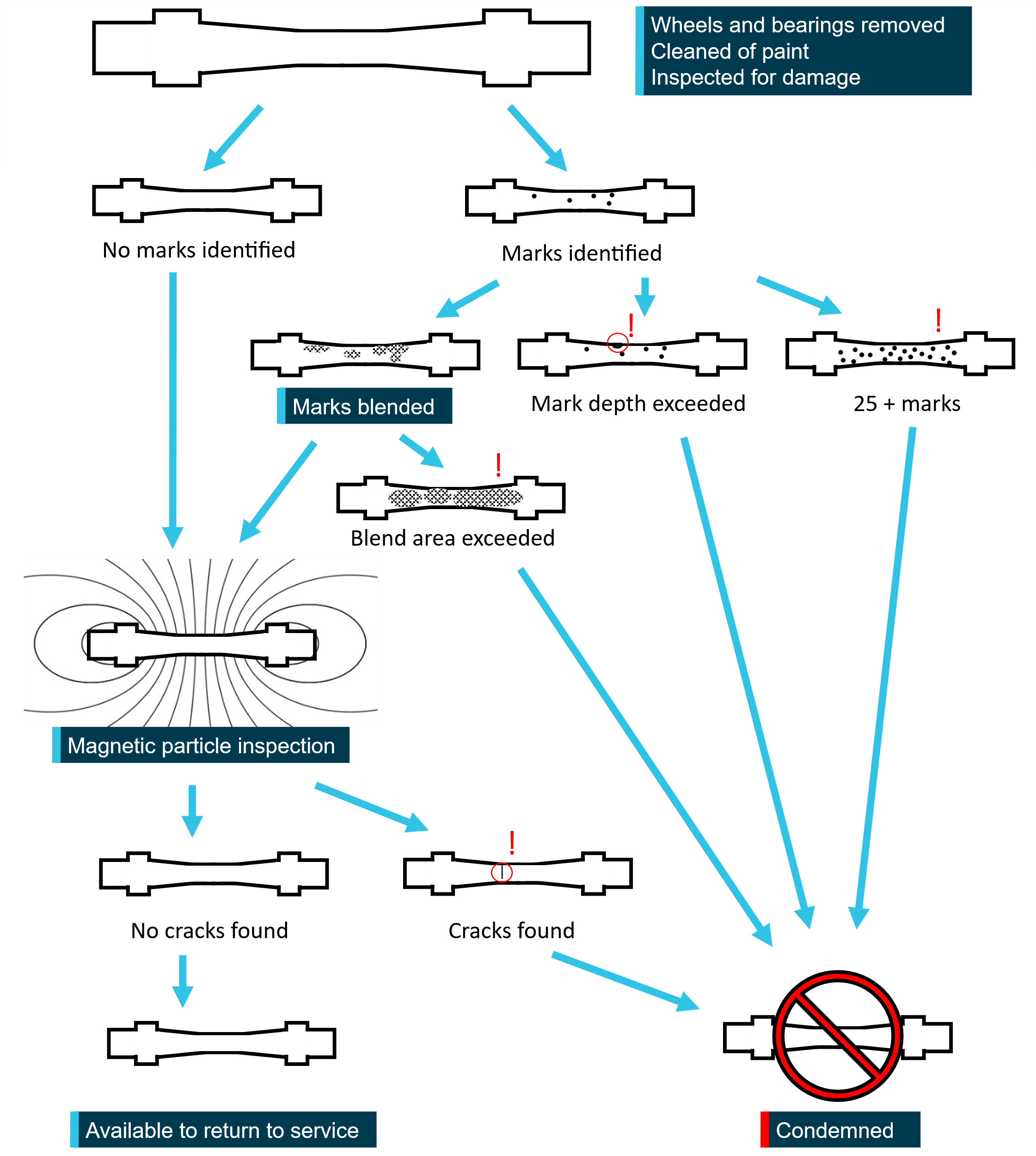
If no marks were identified, the axle would undergo magnetic particle inspection to ensure there were no cracks. If magnetic particle inspection revealed a crack, the axle was to be condemned. If the axle was free from cracking, and met all the non‑barrel‑related requirements, it was able to be fitted with bearings and wheels for return to service.
If marks were identified on the axle barrel, the number and the depth of the indentations would need to be assessed. Where the number of marks or an indentation depth exceeded the maximum, the axle was to be condemned. If all marks were shallower than the applicable maximum depth for that axle design, and there were less than 25 marks, the barrel could be repaired by blending.
One overhauler advised the ATSB that they performed a dimensional tolerance check following blending repair to ensure the constant-diameter centre section of the axle was not thinned beyond the tolerance of the design drawing. Following blending, the axle would be checked for the presence of cracks with magnetic particle inspection. Figure 12 shows a diagram summarising the barrel-related actions during overhaul. There were also many non‑barrel‑related criteria, not described in this report, that needed to be satisfied for an axle to be returned to service.
Figure 12: Diagram illustrating the barrel-related action during axle overhaul
Source: ATSB
Identification and characterisation of axle barrel damage at overhaul
Identification of barrel marks at overhaul was performed once the bearings and wheels were removed from the axle, the paint was stripped, and the axle positioned under appropriate lighting. One overhauler stated that it was possible to identify marks on an axle as they were faceted indents that caught the light. Conversely, the overhauler stated that, without the paint stripped and good lighting, it would not be possible to identify a typical mark, which was around 0.5 mm deep. The overhauler estimated that around 97% of wheelsets that entered an overhaul facility required blending repair. During a visit to a different overhaul facility, it was observed by a transport safety investigator that, for a painted axle, it would be very difficult to differentiate between a chip in the paint and a 0.5 mm deep indent. Another rolling stock operator stated that damage was not visible without paint removal.
Once marks were identified, a depth gauge was used to characterise the depth of the damage to determine if the axle could be repaired, or if it would be condemned. The overhauler stated that it was possible to characterise depth to the nearest hundredth of a millimetre. This overhauler did not perform quality assurance checks or consistency checks on test pieces containing known numbers of marks with known depth. There was also no assessment made by the overhauler regarding the consistency of defect identification and characterisation between workers. This was unlike magnetic particle inspection where practitioners used test pieces to ensure they could detect cracks and held qualifications aimed at assuring some baseline level of practitioner consistency.
Cumulative blending of axles
Pacific National had adopted rule 1.1.12.1 of the AAR Manual of Standards and Recommended Practices Wheels and Axles, G-II [S-659] (AAR, 2019), which specified that no more than 25 blends were allowed on an axle and the total blended area could not exceed the lesser of 20% of the axle barrel surface area and 200 square inches. The AAR standard stated that if the limits were exceeded an axle would either need to be machined19 or condemned.
While the textual interpretation of this rule, confirmed by the AAR, was that the limitation applied over the life of the axle, one overhauler stated that they had interpreted this to mean for each visit to an overhaul facility. In addition, 2 other overhaulers were found to have no means to ensure compliance with these rules. The number of blends, or blended area, was not a parameter recorded in the Pacific National rolling stock database or on a wheelset production sheet. Therefore, it was not possible for the overhaulers to know the total number, or total area, of blending repairs made to an axle during all previous visits to an overhaul facility. Rule 1.1.12.1 applied to all Pacific National axles, including the NB axles.
Narrow-gauge ‘L’ class axle condemnation records
Pacific National provided records of all condemned narrow-gauge ‘L’ class axles for the 10 years prior to January 2023. When an axle was condemned, a free text field description could be populated to indicate the reason. These descriptions were categorised by the ATSB, as shown in Table 1, and it was observed that axles were predominantly condemned for wheel seat issues, not barrel damage.
The number of axles condemned increased after 2017, with substantially more axles condemned in 2018, 2019, and 2020, as compared with the preceding years. Although, over the next 2 years, 2021 and 2022, only a single axle was condemned. There was no update to the Pacific National procedures relating to axle barrels, specifically Wagon Maintenance Manual (WMM) 09-03 Axles,20 around 2017, to explain why more axles were condemned in 2018, 2019 and 2020.
In the data, 2 axles were categorised by the ATSB as ‘cracked’. The free text field descriptions associated with these axles were ‘axle cracked’ and ‘CRACKED AXLE’, for the 2019 and 2022 entry, respectively. The descriptions did not specify where the axle was cracked and other descriptions in the records, such as ‘cracked bearing journal’, indicated that cracks could be found in areas of the axle other than the barrel. Therefore, it was not possible to state conclusively that these axles were condemned for axle barrel cracking.
In the 10 years’ worth of data, 11 out of 94 condemned axles were categorised as condemned for barrel damage by the ATSB based on the free text field description. Over this period, changes were made to axle inspection and maintenance procedures. Up until April 2020, all ‘L’ class narrow-gauge axles were designated 7L7N axles. After this, the NB axles were differentiated from ‘full’ axle-barrel-diameter axles, although the exact date in April when this occurred was not known. Of the 5 axles condemned for barrel damage in 2020, one was an NB axle, one was a ‘full’ axle-barrel-diameter axle, and the axle type of the remaining 3 was unknown as they were condemned prior to April. In the following year, 2021, no axles were condemned.
Table 1: Number of axles condemned between 2013 and 2022
| Year | 2013 | 2014 | 2015 | 2016 | 2017 | 2018 | 2019 | 2020 | 2021 | 2022 |
| Wheel seat issue | 2 | 5 | 9 | 26 | 24 | 0 | ||||
| Barrel damage | 1 | 1 | 4 | 5 | ||||||
| Bearing journal issue | 2 | 2 | 1 | |||||||
| Bent axle | 1 | |||||||||
| Cracked | 1 | 1 | ||||||||
| Other | 2 | 2 | 1 | |||||||
| Unknown | 2 | 2 | ||||||||
| Total | 0 | 0 | 2 | 5 | 5 | 17 | 34 | 30 | 0 | 1 |
Previous NB axle failure due to fatigue
On 23 December 2019, 5 wagons of train 9231, transporting zinc concentrate and copper anodes, derailed on the Mount Isa line, near the township of Mingela, Queensland. These were bulk wagons where axles would be loaded to the 20-tonne maximum for half their journey time and unloaded (empty) for the other half.
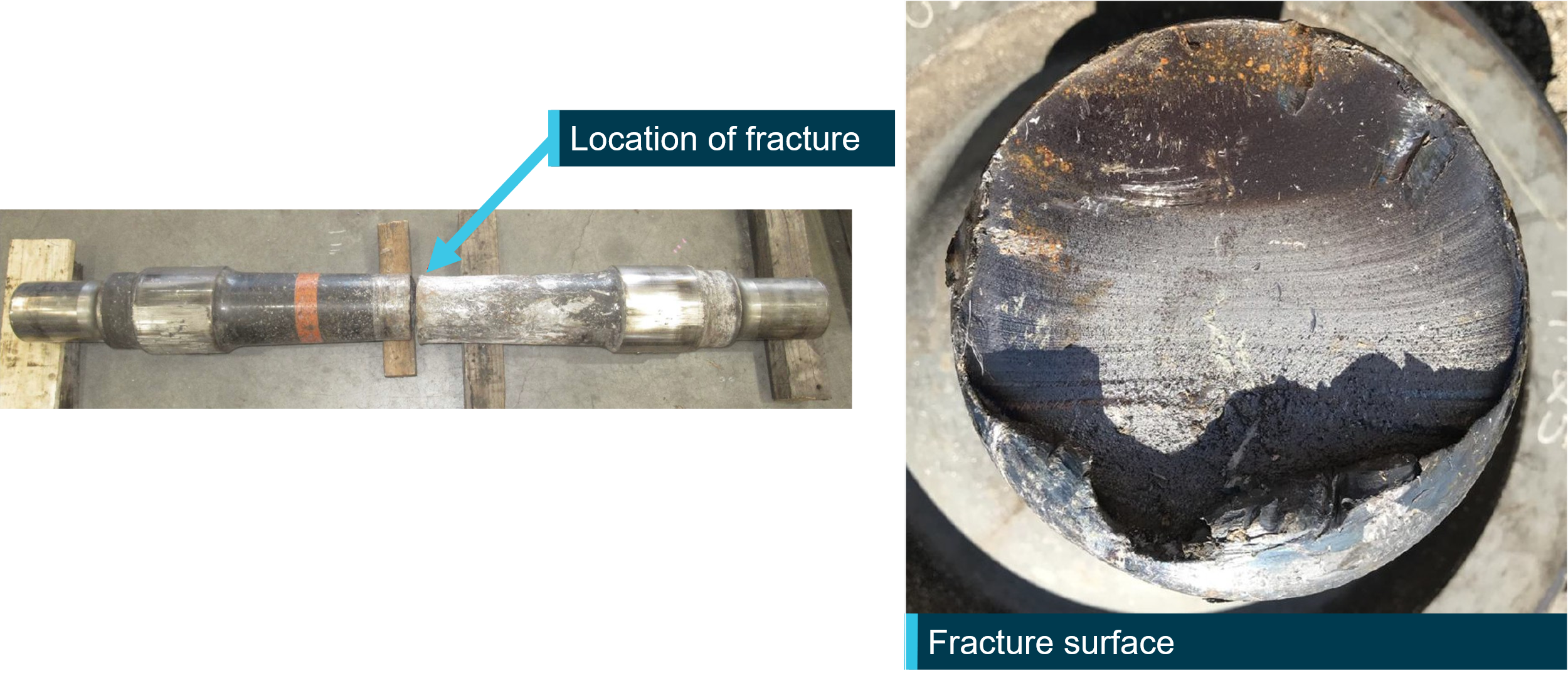
An NB axle, referred to as the Mingela axle, fitted to one of the derailed wagons was found to have fractured near the centre section of the barrel (Figure 13). Pacific National had never before experienced an in-service failure of a 7L7N or NB axle. The fracture surfaces exhibited progression marks followed by overstress fracture. The progression marks were estimated to extend across around 70% of the axle cross-section.
Pacific National commissioned an examination of the fractured Mingela axle, which stated that, while it was suspected that the fatigue crack may have been initiated by ‘a small indentation caused by being struck by a piece of ballast’, examination could not confirm the presence of such an indentation. Magnetic particle inspection performed on the fractured axle did not detect additional indications of cracking on the barrel. The axle was found to meet the compositional and mechanical requirements of the specified material. The report also noted that the axle had been involved in a stationary immersion and derailment event in January 2019 (around 11 months prior to the failure) where floodwaters lifted the stationary train off the tracks.
Figure 13: Fracture location and surface appearance of Mingela axle fracture
Source: Pacific National and Bureau Veritas, annotated by the ATSB
Response to previous NB axle failure
Risk assessment and investigation
In response to the Mingela axle failure, Pacific National undertook several activities over a 13-month period. These activities were directed by the Asset and Infrastructure Services group (AIS group), which held responsibility for the management of rolling stock and related procedures. The AIS group initiated a formal risk assessment according to its local procedures and commenced populating its risk assessment template on 13 January 2020. Six team members were listed on this first revision of the template, revision A.
Pacific National’s associated investigation report for the event completed senior review and sign‑off on 4 February 2020. During the investigation, Pacific National consulted another rolling stock operator, Aurizon, which had used a narrow-gauge axle with a similar design to the NB axle on bulk wagons. Aurizon had experienced in‑service fatigue cracking and failure of axle barrels (see Similar occurrences). The barrel dimensions between the wheel seats were identical for both designs. The axle length, however, was 1,897 mm for the Aurizon axle, as compared with 1,816 mm for the NB design. Aurizon observed initiation of a fatigue cracks from small instances of impact damage attributed to ballast strikes.
Analysis of the Aurizon axle design showed that it did not meet the requirements of the 2009 version of British Standard European Norm (BS EN) 13103 Railway applications - Wheelsets and bogies - Non-powered axles - Design method.21 Aurizon reportedly stated that the axle was found to have a margin of safety less than 1 and be operating in the ‘fatigue zone’.
Pacific National concluded the root cause of the Mingela axle failure was fatigue cracking and determined that:
The design of the Bradken 7L7N axle22 is more than likely inadequate for long term operation at 20T [20 tonnes] axle load.
This axle design is likely to be susceptible to rapid onset of fatigue cracking in the presence of very minor damage, such as that caused by ballast strikes.
The investigation report listed 13 proposed action items to prevent the recurrence of a similar incident. These 13 action items were accepted by Pacific National and input as action items in the Pacific National action tracking database, known as ‘The Shed’.
The AIS group produced revision B of its risk assessment template on 10 February 2020, revision C on 9 September 2020, and the most recent revision prior to the subject accident, revision D, on 19 October 2020. The sign‑off facilitator was the only team member listed for all 4 revisions of the risk assessment template and was the sole team member listed in the most recent revision of the template. The sign‑off facilitator left Pacific National in April 2021.
Many elements of the risk assessment template were not completed strictly in accordance with the template guidance. The template contained 17 risk controls considered by Pacific National, 14 of which appeared to have been accepted for implementation. While there was significant overlap between these 14 risk controls and the 13 action items from the investigation report, there was not a direct one-to-one correlation of items. Documentation of the proposed amendments to existing risk controls, or additional risk controls, in the risk assessment template did not include detailed explanations or justifications on how each control was expected to reduce risk.
The most recent update to the risk assessment template, revision D, included many incomplete fields. Most notably, the ‘Risk Control Review’ fields, where a responsible person and a due date were to be listed, had not been completed for any control item. Additionally, the risks identified during the NB axle risk management activity had not been entered into a risk register.
The overall intent behind the risk control items introduced by the AIS group was to reduce the risk posed by NB axles. The risk levels were outlined in a risk matrix contained within the template (see Appendix A – Risk matrix in the Asset and Infrastructure Services group template) where the greatest possible risk corresponded to a risk rating of ‘Very High (1)’ and the lowest risk corresponded to a risk rating of ‘Very low (25)’.
The scenario used by the AIS group when determining the risk rating was a fractured NB axle with the risk outcome: ‘derailment resulting in single fatality’. The risk template included the following relevant consequence descriptions (safety and health):
Major:
Third party/general public An event resulting in multiple fatalities due to third party error
Critical:
Employee/contractor An event that results in one or more fatalities
Third party/general public: An event that results in one or more fatalities due to Asciano23 [Pacific National] error or failure
The consequence selected by the AIS group for its identified scenario was ‘Major’, and this remained unchanged for all 14 of the accepted risk controls. The template showed that the AIS group determined that the likelihood of the inherent risk (without controls) was ‘Possible’ leading to a risk rating of ‘High (8)’. A number of the proposed risk controls were to reduce the likelihood to ‘Unlikely’, which resulted in a reduction in the risk rating to ‘Medium (12)’.
Pacific National considered replacing all NB axles with full-thickness axles during the risk assessment activity. Replacement of NB axles was determined to reduce the risk of the fractured axle, derailment, and fatality scenario to ‘Low (16)’. Although this was accompanied by an associated business risk, resulting from service disruption and cost, which was assigned the risk rating ‘Medium (13)’.24 In the risk analysis template, it was stated that the ‘inspection regime’ devised to control for the NB axle failure scenario was selected rather than the option to ‘replace’ all NB axles.
The action/control items and changes to axle barrel risk controls were implemented over the period from 13 January 2020 to 15 February 2021. The 13 action items and 14 control items are not described in detail individually in this report. Instead, the following sub‑sections describe the development of axle barrel‑related risk control in response to the Mingela axle fracture leading to the axle barrel‑related risk controls current at the time of the Marmor axle fracture.
Wagon loading limitation
Prior to the Mingela axle fracture, NB axles were used on bulk wagons and lower‑duty wagons. Following the Mingela axle fracture, a risk control was introduced restricting NB axles to service on lower‑duty wagons. Pacific National recorded that NB axles were only fitted to lower‑duty wagons by 28 May 2020. While no comparative analysis was performed between the 2 loading scenarios, Pacific National advised the ATSB that the loading on lower‑duty wagons was less severe than on bulk wagons.
Engineering evaluation of the NB axle design
Following the Mingela axle fracture, Pacific National commissioned an engineering evaluation, dated 29 July 2020, of its NB axle design to:
• Determine if the axle design complies with the current version of BS EN 13103 at its rated capacity; and
• Understand the impact of operational axle loading on the associated fatigue life. In cases, the actual operational loading may be substantially less than the axle rating
The standard used for the evaluation was BS EN 13103-1:2017. The calculation of axle stress in reduced gauge track (metric or close to a metre) axles, applicable to NB axles, was unchanged from the previous version of the standard, BS EN 10103:2009. The report supplied to Pacific National stated that the NB axle was found to meet the requirements of the standard from a ‘stress perspective’. This assessment involved calculating the stress for each section of the axle and comparing it with maximum permissible stresses. While the calculation of the stress in the axle sections was verified, the ATSB found that the process followed to determine the maximum permissible stresses did not use materials test data as outlined in the standard.
The evaluation reported that the critical location, described as the ‘most highly stressed’ location, was the transition between the constant diameter centre section and the outward taper (Figure 7). The stress calculated at this location was 154 MPa and corresponded to the location with the lowest margin of safety, 1.17. In comparison, the calculated stress at this location for the 7L7N design was 125 MPa and the margin of safety was 1.44, when calculated using the same maximum allowable stress value.
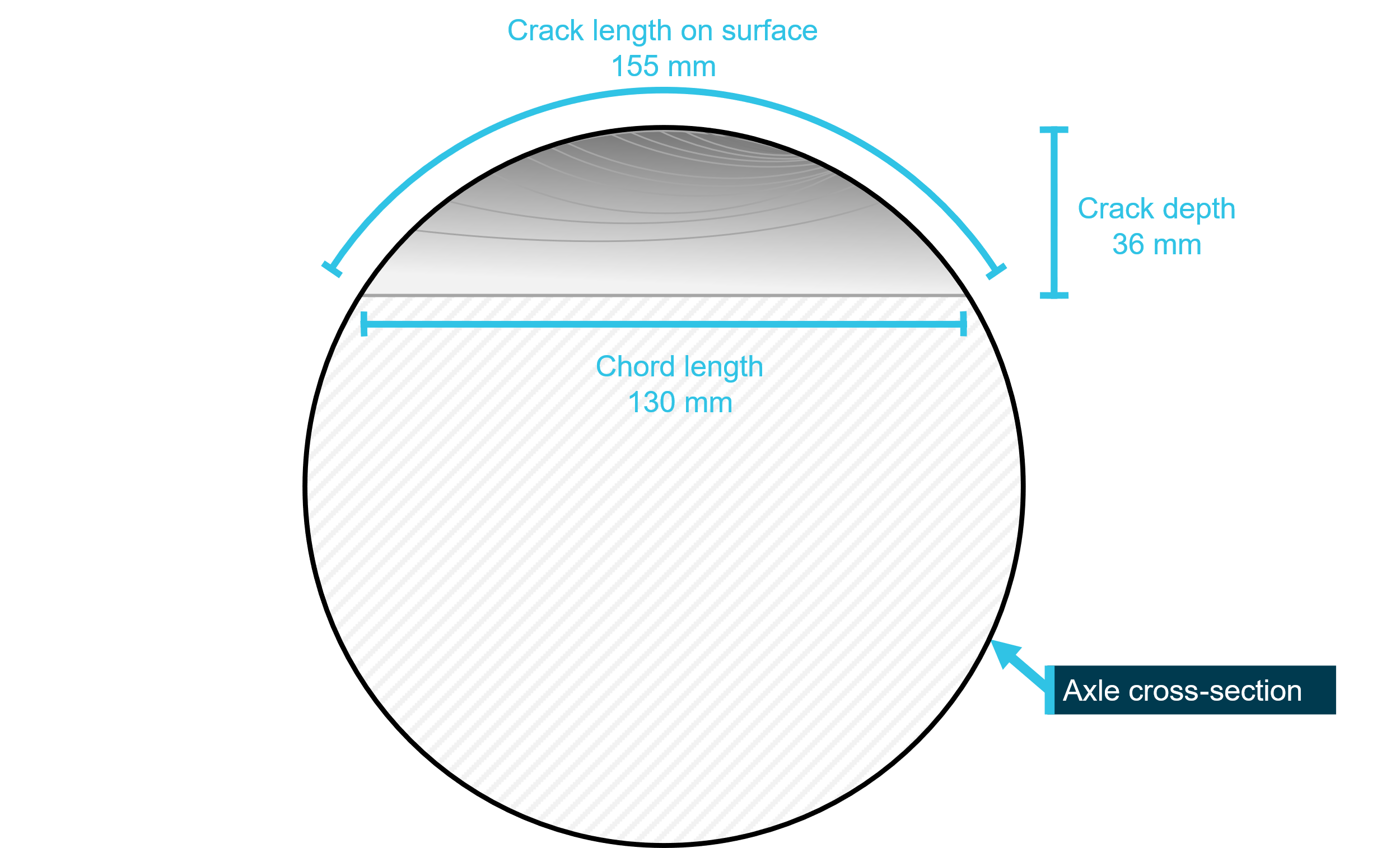
The engineering evaluation stated that the fatigue life of the NB axle ‘was found to exceed 30 years of operation in the undamaged or as manufactured condition’. The critical crack depth25 was stated to be 36 mm for the constant-diameter centre section of the NB axle design (Figure 14). A crack that had progressed to this depth would correspond to a crack length of 155 mm on the curved surface of the axle and a chord length of around 130 mm.
Figure 14: Representation of a critical-depth fatigue crack in an NB axle
Source: ATSB
The report also provided crack initiation intervals and crack growth intervals generated using finite element analysis. While the evaluation was in response to a failure of an NB axle fitted to a bulk wagon, the analysis considered an NB axle subject to loading and track curve profiles indicative of the route between Brisbane and Cairns, used by lower‑duty wagons, for 2 lateral loading conditions, 50 kN and 75 kN. Lateral loading was the term used in the engineering evaluation to describe wheel/rail horizontal force perpendicular to the rail on the side of the more heavily-loaded journal.
Crack initiation interval estimates (Table 2) were produced for 2 notch sizes, not greater than 0.2 mm and not greater than 3 mm. The term crack initiation interval was not explicitly defined in the report, instead the phrase ‘life of the axle to the point of small crack initiation’ was used and this likely meant crack initiation interval in kilometres travelled. For example, analysis predicted that, if there was a hemispherical surface notch with a radius of not greater than 0.2 mm in an NB axle barrel, the axle could travel 654,000 km before the notch would initiate a small crack, in the case where the lateral load was 50 kN. In this example the initiated crack would have a length of around 0.4 mm on the axle barrel surface and would not necessarily be reliably detectable with non-destructive techniques.
Table 2: Distance travelled till crack initiation
| Lateral load | Hemi-spherical surface notch size radius | Distance till crack initiation |
| 50 kN | not greater than 0.2 mm | 654,000 km |
| not greater than 3 mm | 172,000 km | |
| 75 kN | not greater than 0.2 mm | 195,000 km |
| not greater than 3 mm | 59,000 km |
The crack growth intervals, or the distance it would take a chordal crack, of depth 1 mm, 2 mm, and 3 mm, to propagate to the critical depth of 36 mm was modelled for the same Brisbane to Cairns route for the 2 lateral loading conditions (Table 3). For example, the analysis predicted, for the 50 kN lateral load condition, a 2 mm deep chordal crack, which would appear 35 mm long on the axle surface, would grow to a depth of 36 mm after the wheelset travelled 397,000 km. Such a crack would appear 155 mm long on the axle surface.
Table 3: Distance travelled for a chordal crack to propagate till critical depth
| Lateral load | Chordal crack depth | Crack length on surface[1] | Distance till crack initiation |
| 1 mm | 25 mm | 8,700,000 km | |
| 50 kN | 2 mm | 35 mm | 397,000 km |
| 3 mm | 43 mm | 148,000 km | |
| 1 mm | 25 mm | 1,300,000 km | |
| 75 kN | 2 mm | 35 mm | 156,000 km |
| 3 mm | 43 mm | 100,000 km | |
| [1] The crack length on the surface of the axle that corresponded to the chordal crack depth was calculated by the ATSB | |||
Scheduled inspections
Changes were made to the scheduled inspection of NB axles following the Mingela axle fracture. The wagon maintenance schedule applicable to wagons fitted with NB axles included 3 inspection types, ‘P’, ‘A’, and ‘B’ inspections, at 250,000 km, 500,000 km, and 1,500,000 km intervals, respectively. Through this schedule, a wagon and the installed wheelsets would be subject to inspection every 250,000 km in the repeating sequence P, A, P, A, P, then B.
At the time of the Mingela axle failure, Pacific National procedure WMM 09-03_08 Axles (version date 29 September 2009) detailed the requirements to be met at the different types of inspections with respect to the condition of the axle barrel.
On 4 February 2020, Pacific National issued Rolling Stock Notice E 20-001V2 which:
- Reduced the allowable depth for damage to be blend repaired from 3 mm to 1 mm for NB axles.
- Introduced the requirement for wagons with NB axles fitted to be lifted up from the bogies at ‘P’ and ‘A’ inspections to allow rotation of the axles and provide access to clean and visually inspect the full circumference of the axle barrel. Previously this was not a requirement.
- Reiterated that the visual inspection of the axle barrel, which would occur at on-train, ‘P’, ‘A’, and ‘B’ inspections, between the wheel seats shall be conducted for the presence of cracking, transverse or circumferential scoring, grooves, gouges, scratches, chisel marks, or similar indentations. Axles identified with surface defects were to be removed from the bogie. Wheelsets removed for damage were to have the area(s) of damage highlighted before dispatch to an overhaul facility for repair. Pacific National reiterated that procedures did not allow for any marking of any depth to remain unblended and expected all damage to be identified for repair.
On 15 February 2021, Pacific National updated its procedures again releasing WMM 09‑03_09 Axles, which:
- Reduced the allowable depth for damage to be blend repaired to 0.5 mm for NB axles.
- Specified that NB axles could not be machined.
- Changed the requirement to comply with the entirety of Section 1 of AAR Manual of Standards and Recommended Practices Wheels and Axles, G-II [S-659], to a requirement to meet only specific referenced rules.
- Introduced an interval-based requirement for an NB axle to be removed from bogies and cleaned of paint to enable magnetic particle inspection at ‘B’ inspections, every 1,500,000 km.
In the risk assessment template, the introduction of the interval-based magnetic particle inspection was associated with values sourced from the engineering evaluation. Specifically, the total time ‘from defect to failure’ was considered. This was a combination of a crack initiation interval and a crack growth interval. The initiation interval Pacific National selected was a ‘notch radius less than 0.2 mm time to crack propagation’ and most closely aligned with the value of 654,000 km in Table 2. The growth interval was described as ‘growth to critical – initial depth 2 mm’ and most closely aligned with the crack growth interval of 397,000 km in Table 3. The combined total was 1,051,000 km. Also included in the risk assessment template was an estimate that magnetic particle inspection would occur every 1,000,000 km. Pacific National was not able to provide an explanation as to how these 2 values (1,051,000 km and 1,000,000 km) exactly related to each other and to the introduction of the interval‑based magnetic particle inspection at the ‘B’ inspection, every 1,500,000 km.
While Pacific National updated its axles procedures again on 17 May 2021, with the release of WMM 09-03_10 Axles, there were no changes related to axle barrel inspection introduced with this version. This version was current at the time of the Marmor accident. Section 2, titled ‘Workshop inspection and repair’, contained the following parts relating to axle barrels:
2.2.5 Axles Barrel S-659 Rule 1.1.11 & 1.1.12
2.2.5.1 Bogie with 7L7NB wheelsets shall be removed from wagons at A and P inspections to enable thorough inspection of full circumference of axles.
2.2.5.2 At B inspections, 7L7NB wheelsets shall be removed from wagons with barrels cleaned of paint to enable MPI inspections. Barrels shall be repainted post MPI.
2.2.5.3 7L7NB axles are required to have barrel cleaned of paint to enable MPI inspection for all scopes of wheel set overhaul. The barrel shall be repainted post MPI.
2.3 Axle NDT26 Following Derailment
2.3.1 If a defect is detected on the axle surface, the full surface area of the axle shall be tested by MPI or radial ultrasonic procedures
2.3.2 If wheels do not require removal, the axle shall be tested using angled probe ultra-sonic procedures to inspect the wheel-seats, and near and far end scans in both directions. Ultrasonic Inspection shall be conducted per AS1065-198827 for forgings.
Note: Wheelsets involved in derailments shall be suitably identified.
2.4 Recording and Reporting
2.4.1 An electronic record is to be kept by the service provider of axle inspection & testing including axle number, date of inspection, inspection and test results for each axle for a minimum period of 12 years.
2.4.2 All defective axles shall be separately recorded with a full description and location of the defect(s), together with a report on the axle’s history and any other relevant information.
2.4.3 Inspection records shall be provided to Pacific National upon request.
Section 3, titled ‘Axle repair - General’, contained the following parts relating to axle barrels:
3.1 Repair Axle Barrel Defects
3.1.1 Refer to S-659 Rule 1.1.12
Note: 7L7NB axles are limited to damage having 0.5mm maximum depth. Damage with a depth greater than 0.5mm shall result in the axle being scrapped.28 7L7NB axles have no allowance for machining.
The rules of AAR Manual of Standards and Recommended Practices Wheels and Axles, G-II [S-659], referenced by Pacific National, stated:
1.1.11 Welding on axles is not permitted, and any axle showing welding or cutting torch damage is scrap. Only electrochemical metal deposition processes, covered in Rule 1.2.6, are approved repair techniques.
RULE 1.1.12 Axle Surface Defect Repair
The axle body must be cleaned to ensure that the body is sufficiently free of rust, oil, paint, and dirt to enable visual and magnetic particle inspection.
1.1.12.1 All axles with surface defects 1/8 in.29 deep or deeper must be scrapped or repaired using the full-body machining technique according to paragraph 1.1.2 or 1.1.12.3. All cracks must be removed and blended smoothly into the contour of the axle body. Surface defects such as nicks, gouges, or deep scratches less than 1/8 in. deep, having features with less than a 2-in. radius must be removed and blended smoothly into the contour of the axle body. Repairs that result in a radius less than 2 in. are not blended smoothly into the contour of the axle body and are not acceptable.
The following criteria must be met:
• Surface roughness of such repairs shall not exceed 90 microinch Ra.
• Repairs to circumferential defects such as those caused by brake rod interference may cover the entire axle circumference but can be no more than 6 in. wide.
• Removal must be performed such that all marks are aligned with the length of axle.
• Operations must not produce discoloration at any time during the process.
• No more than 25 such repairs shall be allowed to each axle.
• Repairs cannot be joined for the purpose of reducing the total number of repairs.
• In no case shall grinding repairs exceed 20% of the surface area of the axle body or 200 in2, whichever is less.
• Final-step grinding media must be 80 grit or finer when finishing by hand or 120 grit or finer when using power tools.
• If a multi-step finishing process is employed, more aggressive media (rougher) may be used in the initial step provided the final-step finishing removes all evidence of the rougher medium.
Axles that fail to meet these criteria must be machined in accordance with paragraph 1.1.12.3 or scrapped.
1.1.12.2 All repairs on axles that have been in service must be magnetic-particle-tested by the wet method and shall be completely free of defects.
1.1.12.3 Axle bodies may be machined, providing surface defects can be removed without going below specifications. The surface roughness of the machined body shall not exceed 250 microinch Ra. Any axle body that has been machined must be magnetic-particle-tested by the wet method after machining and shall be completely free of defects.
1.1.12.4 Dust guard repairs should be treated in the same manner as the axle body repairs with the following exceptions:
• Dust Guard surface defects with less than 1/8-in.-deep circumferential V-notch condition must be corrected by grinding to 1/8-in. radius or more and may be corrected by filing, sanding, or machining to remove the defect.
• If the dust guard area is corrected per the above procedure to be considered a fitted application, care must be exercised to ensure that the affected area is completely sealed to prevent water and/or contamination from entering the journal filet area.
The requirements of Pacific National axle procedures were implemented using inspection checklists. The check-box items relating to the axle barrel on the ‘P’, ‘A’, and ‘B’ inspection checklists, current at the time of the accident, are contained in Table 4. The ‘A’ and ‘B’ checklists stated the 3 mm depth limitation for blending applicable to 7L7N axles but did not state the 0.5 mm depth limitation applicable to NB axles.
Table 4: Axle barrel‑related check-box items for the ‘P’, ‘A’, and ‘B’ inspection checklists
| Checklist | Description of task/check | Procedure | Action |
|---|---|---|---|
P Inspection WMM 01-03_12 | WHEELS AND AXLES | ||
| Check condition & gauge (WMM 14-01) | WMM 09-11 | IG | |
| SPECIAL WAGONS | |||
| RNAY, RNBY, RNCY wagons with 7L7NB axles, lift wagon to allow rotation of axle and access, clean axle barrel and visually inspect entire axle barrel | WMM 09-03 WMM 09-01 | I | |
A Inspection WMM 01-04_16 | WHEELS AND AXLES | ||
| Check wheel & Axle condition (Barrel strikes more than 3mm deep) | WMM 09-11 WMM 09-03 | I | |
| Gauge & Record Wheels (WMM 14-01) | WMM 21-24 | G | |
| Paint a flash of white paint on wheel rim | WMM 09-05 | I | |
| SPECIAL WAGONS | |||
| RNAY, RNBY, RNCY wagons with 7L7NB axles, lift wagon to allow rotation of axle and access, clean axle barrel and visually inspect entire axle barrel | WMM 09-03 WMM 09-01 | I | |
B Inspection WMM 01-05_18 | WHEELS AND AXLES | ||
| Check wheel & Axle condition (Barrel strikes more than 3mm deep) | WMM 09-11 WMM 09-03 | I | |
| Gauge & Record Wheels (WMM 14-01) | WMM 21-24 | G | |
| Paint a flash of white paint on wheel rim | WMM 09-05 | I | |
| SPECIAL WAGONS | |||
| RNAY, RNBY, RNCY wagons with 7L7NB axles, remove axle, clean axle barrel and magnetic particle entire axle barrel | WMM 09-03 WMM 09-01 WMM 01-23 | I | |
Legend I Inspection Required Only G Gauge or Measure | |||
Non-ongoing axle inspection program
Pacific National initiated a program of one-off inspections of NB axles in response to the Mingela axle failure. This included a magnetic particle inspection program to identify cracked axles and a visual inspection program to identify barrel damage.
The magnetic particle inspection program was initiated on 9 January 2020, when Pacific National issued Rolling Stock Notice E 20-003. This program was initially limited to a sample of NB axles. Pacific National could not confirm the sample size and the broader population from which the sample originated. Rolling Stock Notice E 20-003 included an MPI/Damage Inspection Record pro forma that was to be completed and emailed to the relevant group within Pacific National. One record of the pro forma, containing the results for 23 axles, all of which required blending repair, was provided to the ATSB. Damage with depth ranging from ‘under 3 mm’30 to ‘0.01 mm’ deep was recorded. As magnetic particle inspection would require removal of paint, identification of damage during the one-off magnetic particle inspection program would have occurred under conditions similar to those for a ‘B’ inspection. Accordingly, the records indicated that damage with depth as small as 0.01 mm could be identified under ‘B’ inspection conditions.
On 3 February 2020, version 2 of Rolling Stock Notice E 20-003 was issued specifying that magnetic particle inspection was to be conducted on all NB axles. Pacific National indicated that magnetic particle inspection of all NB axles was completed in August 2021. Inspection records conforming to the pro forma could not be provided by Pacific National for all axles. In the time between when version 1 of Rolling Stock Notice E 20-003 was issued and the completion of the program, the depth of damage that was acceptable for blending was reduced twice (see Reduction in acceptable blend depth).
The visual inspection program was initiated on 4 February 2020, when Pacific National issued Rolling Stock Notice E 20-004V2. This program required visual inspection of the barrels of all NB axles. Rolling Stock Notice E 20-004V2 stated that this inspection could be conducted as an ‘on-train’ inspection and detailed that any cracking, transverse or circumferential scoring, groove, gouges, scratches, chisel marks, or similar indentations were unacceptable defects. Axles identified with such marks were to be removed from service, the areas of damage were to be indicated, and the axle dispatched to an overhauler. Rolling Stock Notice E 20-004V2 included an Axle Damage Inspection Record pro forma that was to be completed and emailed to the relevant group within Pacific National. Pacific National indicated that visual inspection of all NB axles was completed as of 19 October 2020; however, it was unable to provide any completed inspection records conforming to the pro forma.
Pacific National was asked to provide evidence that, during visual inspection, inspectors were able to detect all damage on the axle. The evidence provided was not related to on‑train, ‘P’, or ‘A’ inspections and did not demonstrate that all marks were identified at these inspections. Instead, records relating to the non-ongoing magnetic particle inspection program were provided, where the wheelset would have been removed from the bogie at an overhaul facility in a manner consistent with a ‘B’ inspection.
Wayside monitoring limitation
As part of the response to the Mingela axle failure, Pacific National modified its response to a particular wheel impact load alarm issued by the Queensland Rail wayside monitoring system. If a wheel impact load alarm greater than 196 kN was issued, Pacific National would schedule the wheelset to be removed from its position and sent to an overhaul facility no later than 20 weeks following the alarm.
Pacific National stated that the wheel impact load detector alarms were related to physical defects or damage present on wheels and were not a representation of the axle loads. For example, a load alarm could indicate a 10 mm size wheel flat31 or spall32 on a wheel and did not necessarily indicate that the axle, bogie, or wagon was overloaded.
Reduction in acceptable blend depth
On 3 February 2020, when Rolling Stock Notice E 20-003V2 was issued, the damage depth prompting an NB axle to be condemned was reduced from the AAR standard of around 3 mm to 1 mm. This requirement to condemn NB axles if barrel damage was found with depth greater than 1 mm was also listed in Rolling Stock Notice E 20‑001V2, released on 4 February 2020. Rolling Stock Notice E 20‑003V2 and Rolling Stock Notice E 20‑001V2 expired on 2 August 2020 and 4 August 2020, respectively. On 15 February 2021, the damage depth prompting an NB axle to be condemned was further reduced to 0.5 mm with the publication of revision 9 of WMM 09‑03 Axles.
These changes to the barrel damage depth at which an NB axle was to be condemned, were not included in the 13 action items in the Mingela axle failure investigation report, nor where they described as part of the 14 accepted risk controls detailed in the risk assessment template. Pacific National was not able to provide the rationale for the depths it selected beyond the statement that condemning axles with shallower damage would be more conservative.
Machining axles
Prior to 15 February 2021, Pacific National procedures contained the requirement to comply with the entirety of Section 1 of AAR Manual of Standards and Recommended Practices Wheels and Axles, G-II [S-659]. This standard allowed an axle to be machined if the cumulative damage limits were exceeded, provided none of the damage exceeded the 3 mm depth limit. After this date, with the publication of revision 9 of WMM 09‑03 Axles, Pacific National specified that NB axles ‘have no allowance for machining’. As with the reduction in acceptable blend depth, this change to risk controls was not included in the 13 action items in the Mingela axle failure investigation report, nor were they described as part of the 14 accepted risk controls detailed in the risk assessment template.
Organisational information
Pacific National
Risk management procedures
PN-PRO-SAF HSE Risk Management Procedure, issued 18 November 2022, was Pacific National’s procedure for risk management at the time of the accident. The purpose of the document was to outline the requirements for identifying, assessing, and recording Health, Safety, Environment, and Sustainability (HSE) risks within Pacific National. It detailed the processes, tools, and requirements for HSE risk management. There were 5 steps outlined in the risk management process:
• Establish Context:
Defines the parameters within which risks must be managed and sets the scope for the rest of the risk management process.
• Risk Assessment:
Hazard identification – develop a comprehensive list of HSE hazards/aspects; and
Risk assessment – assess likelihood and consequence, determine cause, and identify existing preventative and mitigating controls.
• Risk Control:
Risk evaluation (select, implement, and monitor the effectiveness of specific risk controls following the hierarchy of control); and
Risk treatment (assign, implement and monitor action plans for further mitigation of HSE risks to SFAIRP).33
• Risk Monitoring and Review Risk
Monitor, review, and update (review progress and developments, check actions effectiveness, identify new risks)
• Risk Communication and Reporting
Review, and report the risk profile biannually to the HSE Executive Committee.
There were 5 risk assessment processes listed for identifying and assessing risks. This enabled Pacific National to undertake a level of risk assessment commensurate to the context, type, and scale of a particular risk. These processes were:
• Bow Tie Risk Assessment – this provides for a formal, more rigorous level of risk identification by identifying causal pathways and controls for specific risk events; this process underpins the Pacific National approach to Critical Risk Management.
• Formal Risk Assessment – this provides for a formal, more rigorous level of risk identification and treatment.
• Safe Work Method Statement (SWMS) – addresses high risk work activity risk in a logical sequence, identifying hazards and describing risk control measures.
• Take 3 – this provides for an individual level task related risk assessment.
• Hazard Reporting – outlines the process for hazard reporting and resolution.
Guidance in the procedure pertaining to the ‘Formal Risk Assessment’ stated that the main technique for this type of assessment was a workplace risk review and control (WRRC). The procedure also stated that ‘risk reduction action plans’ were to be developed when existing risk controls were inadequate or inadequately implemented, or if additional risk controls were identified that required implementation. These plans were to be documented in the WRRC and raised in Pacific National’s action tracking database.
The procedure required ‘Each Operation’ to maintain a risk register in a risk management software package provided by the Camms Group.34 The risks recorded in the risk register were to be reviewed and validated when a WRRC was conducted. The operational risk register (Camms) was to be monitored, reviewed, and updated when a new scenario or hazard was identified.
Control owners35 were tasked with reviewing the effectiveness of the risk controls they were allocated. The effectiveness review was to be provided to the risk owner36 to inform their review. Reviews were to be conducted every 6 or 12 months depending on the criticality of the risk.
Pacific National’s risk management procedure also outlined the training and competency requirements for conducting activities contained in the procedure. The ‘Pre-requisite competency’ for conducting the ‘Formal Risk Assessment’ activity was ‘completion of the Pacific National risk management module’ for which the manager was considered ‘Responsible’.
Risk management in the Asset and Infrastructure Services group
Within Pacific National, the management of rolling stock and related procedures, including the assessment and incorporation of new practices, was the responsibility of the AIS group. This group routinely performed formal risk assessments for issues associated with rolling stock infrastructure. The AIS group used a Pacific National template, first created in 2012, to document its formal risk assessments. The guidance text in the template included the following information:
• Team Members where possible are to include one person who is trained in conducting risk assessments to facilitate the process and at least one person involved in the process being assessed.
• The risk assessment must be registered on the relevant risk assessment register and a summary of the assessment included in the operational or site risk register.
The template allowed the group to:
- establish the context and define the scope of the risk assessment
- identify a list of hazards and assess the risk of those hazards by assigning a likelihood and consequence level before and after controls were introduced
- select controls and assign a responsible person with ensuring the implementation of each control.
There was also a ‘Risk Control Review’ section with ‘Responsible Person’ and ‘Due Date’ fields. Instructions for this section stated the ‘responsible manager for the risk assessment must arrange for a review of the risk assessment to ensure all additional controls have been fully implemented and are effective in controlling risk’. There was no field for detailing how the effectiveness of a particular control was to be evaluated.
Outcomes of the AIS group risk assessment activities included the implementation of risk control measures. The implementation of risk controls was on most occasions tracked through Pacific National’s action tracking database. For example, an update to a procedure document would be created as an action in the database and listed as complete when the updated version of the document was issued. The AIS group did not maintain a risk register, nor did the risk management activities conducted by the group appear to interface with the operational risk register. When asked about the group’s use of a risk register, Pacific National stated that the requirement was not consistently communicated across all areas of the operation and, while some different business units did compile their own registers, the AIS group did not.
While the members of the AIS group held diverse engineering and rail-related qualifications, Pacific National was able to provide a record for only one member of the group as having completed a Pacific National specific risk management qualification. This qualification was completed in 2014 and, while the worker was involved in developing revision A of the formal risk assessment undertaken in response to the Mingela axle failure, they were not the ‘Responsible Manager’ or the ‘Sign off Facilitator’. When asked about risk management training programs available to, or likely to be completed, by members of the AIS group, Pacific National stated that risk assessment training at that time was peer-to-peer and read-and-interpret training.
Regulator’s risk management expectations
It was a legislative requirement of accreditation that a rail transport operator have a systematic approach to managing safety risks, known as a safety management system. The Office of the National Rail Safety Regulator (ONRSR) provided a guideline for safety management systems, which needed to include risk management systems and procedures (ONRSR, 2019). ONRSR’s minimum expectation relating to risk management systems and procedures were:
• Scope, context and criteria for the management of safety risks arising from the RTO’s [rail transport operator’s] railway operations;
• Comprehensive and systematic assessment of safety risks arising from the RTO’s railway operations, including risk identification, analysis and evaluation;
• Tracking of any risk treatment activities required through to implementation and closure;
• Ongoing monitoring and review of the identified risks and the adequacy of the control measures used to manage them.
• Recording and reporting of risk management activities and their outcomes to the duty holders and governing bodies within the RTO; and
• Communication and consultation arrangements to ensure relevant stakeholders and subject matter experts are involved at all stages of the risk management process.
ONRSR went on to specify, under ‘Recording and Reporting’ that an operator will have systems and procedures to require:
• A record of the following information in a risk register or supporting documentation:
- the risks identified;
- the individual within the RTO organisation that owns each risk;
- the potential causes of each risk;
- the potential consequences of each risk;
- the control measures considered to eliminate or minimise the risk;
- reasons for selecting certain control measures and rejecting others;
- the relationship between control measures and their associated risk(s);
- references to other locations in the SMS [safety management system] where further details on control measures can be found;
- the individuals within the RTO organisation or the interfacing party with responsibility for implementing control measures;
- the magnitude and severity of the consequences should the risk be realised;
- the likelihood of the consequences materialising;
- the resultant level of risk;
- any uncertainties or assumptions made in the analysis, particularly in relation to assigning likelihood, severity and risk levels;
- the date each risk was last assessed or reviewed; and
- the status of each risk, including a demonstration of whether risks are reduced SFAIRP [so far as is reasonably practicable].
• The risk register to be treated as a live document and used as a reference point for managing safety;
• Risk assessments conducted at a local level to link into the organisation-wide risk assessment processes;…
Under ‘Monitoring and review’ ONRSR specified that an operator will have systems and procedures to:
…Describe how risks are to be reviewed, which as a minimum should involve:
- a review of the accuracy of the risk assessment, including the effectiveness of existing control measures;…
ONRSR published a safety message reiterating operator risk register requirements under Rail Safety National Law (ONRSR, 2025, August 26). In it ONRSR highlighted ‘missing information, reasons and justifications’ as a ‘poor practice’ it has observed. ONRSR provided the specific example:
vague or unclear reasoning such as a 'likelihood' score of '4' becomes '2' with implementation of control 'XYZ' but no explanation how the control will reduce the risk
An example of ‘good practice’ included when it was ‘clear how controls listed will be effective in mitigating the risks’.
Similar occurrences
ATSB investigation RO-2017-013 related to the derailment of bulk acid train 9T90, near Kimburra, Queensland, on 28 September 2017. The derailment, located on the Mount Isa line, resulted from an axle failure. A fatigue crack of a detectable size was present in the axle at the time of the previous routine axle inspection, but was not detected and failed in-service. On 15 August 2018, a second derailment resulting from an axle failure associated with the same rolling stock operator and line, was included in the scope of the investigation. During the investigation, the ATSB conducted a review of past axle failures experienced by the operator, identifying 3 additional instances. All failed axles were of the same design fitted to bulk wagons.
Following each failure, the operator incrementally implemented safety actions. The operator performed fleet-wide magnetic particle inspections of the axles with this design and where an axle with cracks was detected, it was removed from service. The ATSB’s investigation identified that the axle design was susceptible to fatigue cracking due to relatively minor damage that was not reliably detected prior to failure. Relatively minor damage in this report was associated with a damage depth of 0.2 mm.
Ultimately, the operator undertook a program to replace all axles conforming to the susceptible design with a new axle design, which had a 165 mm diameter centre section. During the replacement period, the susceptible axles were to undergo magnetic particle inspection after no more than 65,000 km travelled.
The operator commissioned a finite element analysis of the susceptible design, which computed a critical crack depth of 110 mm (over half the axle diameter) when under self‑weight bearing of a full 20-tonne tanker (bulk wagon) and centrifugal loading. The critical crack depth was consistent with the depth of the failed axles.
Safety analysis
Introduction
On 29 January 2023, at about 1910 local time, an axle on Pacific National freight train 82P7 wagon RNCY137-T failed resulting in a derailment and separation of 8 wagons over a level crossing. Train 9F02, travelling in the opposite direction, collided with a container from the front portion of train 82P7 that was fouling the up line.
The investigation found there were no technical faults with the trackside infrastructure and the condition of the bogie and wagon did not contribute to the axle failure. Similarly, there was no evidence that train speed, handling, or operational performance contributed to the derailment.
This analysis will examine the reason for the axle fracture, the greater risk presented by the NB axle design and the effectiveness of axle barrel fatigue risk controls associated with the NB design. It will also discuss the risk management processes used by those responsible for rolling stock, successive blending repairs of all axles, and the recent inspections of the subject axle.
Failure of axle serial number 7L7NB4726
The appearance of fracture surfaces on the failed axle was consistent with fatigue crack growth followed by overstress failure. The nature of the fatigue growth, starting from the circumference and progressing through over half of the axle cross-section, was consistent with rotational bending subject to low nominal stresses. This would be the anticipated loading scenario for a rail axle, a rotating component, subject to many cycles at low nominal stress.
Analysis of the axle material microstructure, hardness, and elemental composition found that there was no evidence to indicate an issue with the material. Consequently, an issue with the material was excluded as a reason for the axle failure.
If the fatigue life of the failed axle was finite, a fatigue crack may have initiated in the absence of a stress concentrating feature. An engineering evaluation of the NB axle design, which referenced BS EN 13103‑1:2017, found that the stress calculated for each section of the axle was below the maximum permissible stress indicating infinite fatigue life. While calculations were validated, review of this evaluation by the ATSB found that the methodology used to determine maximum permissible stress did not use material test data as described in the standard. Furthermore, analysis of an axle design from another operator was found not to meet BS EN 13103:2009 even though the same formulae for stress calculations would have been used and the design dimensions were almost identical. This analysis was not available to the investigation to understand why 2 very similar designs achieved different outcomes. Accordingly, there was insufficient evidence to conclude that the NB axle design likely had finite fatigue life in the undamaged condition at the operational loads.
The historic loading of the fractured axle was explored as a reason why a crack may have initiated on this axle, or as a reason why a crack grew to a critical size in service. The axle had triggered weighbridge wayside alarms on 4 occasions in the year prior to the accident. Depending on the distribution of goods in the wagon, it was possible that the wagon load will not be evenly distributed over the 8 axles of the triple-pack, potentially resulting in axle load above alarm levels. Nonetheless, Pacific National’s records indicated that the wagon, to which the axle was fitted, was not loaded above the allowed wagon load limit in the year leading up to the accident. Therefore, it was likely the axle was not consistently operated in excess of its 20-tonne design load. Furthermore, other axles triggered load alarms within this period, and they did not fail. Pacific National stated that ‘isolated events of overload’ should not damage the axle as it had a safety margin of 1.17 when assessed in accordance with BS EN 13103‑1:2017. As previously discussed, there was some uncertainty associated with this assessment. Periods of higher loads could be associated with periods of faster crack growth, but it was not possible to correlate these 4 alarms, or any other known events, with features on the fracture surface. Overall, there was insufficient evidence to indicate that overloading of the axle contributed to the failure.
The circumference of both halves of the fracture surface was substantially damaged, presumably, once the axle failed but remained attached to the bogie by the bearings and was dragged along between the rails. Consequently, the location on the fracture surface where the fatigue crack appeared to originate was destroyed and an initiating feature could not be identified and characterised. Nevertheless, historical evidence of axle fractures has shown that:
- cracks have been detected on 154 mm dimeter axle barrels and were observed to originate from surface marks acting as crack initiating features
- there was an example (RO-2017-013) of a failure in a similar axle design where the initiating feature, a 0.2 mm deep instance of surface damage, was able to be identified and characterised
- a reduction in fatigue strength resulting from surface damage is acknowledged in the literature
- Pacific National attributed cracking in NB axle barrels to ballast strike damage.
Therefore, it was very likely that the fatigue crack initiated from damage to the barrel surface.
Contributing factor It was very likely that impact damage to the axle initiated a fatigue crack that propagated until failure and resulted in the derailment of train 82P7. |
NB axle design and failure risk
The NB axle was designed in 2004 as a reduced diameter (154 mm) version of the 7L7N axle (165 mm barrel diameter). This appeared to be a narrow-gauge version of the standard Association of American Railroads (AAR) ‘L’ class axle. The standard BS EN 13103:2001, current at that time, did not consider wheelsets for reduced gauge track (metric or close to a metre). Nevertheless, as discussed above, there was insufficient evidence to conclude that the NB axle design had finite fatigue life in the undamaged condition at the operational loads.
Up until the accident, after around 20 years of an expected 30-year service life, there were 2 axles condemned for being cracked, one of which was positively identified as an NB axle, the other was either NB or 7L7NB. There was insufficient information to establish whether these 2 axles were cracked in the region of the axle barrel. Pacific National had only experienced one previous in-service axle failure resulting from fatigue (Mingela) and this was an NB axle. When the other operator’s data was included, there had been a total of 6 in-service failures of 154 mm barrel-diameter axles resulting from fatigue, prior to this axle failure. Notably, these were axles fitted to bulk wagons. The conflicting design assessments and the limited data relating to fatigue cracks in NB axles meant that the ATSB was unable to establish whether or not the NB axle design met the requirements of the BS13103:2009/BS EN 13103-1 standard and would be expected to meet a 30-year expected fatigue-free life.
While it was possible that NB axle design met the standard, Pacific National’s investigation into the Mingela derailment found that the NB axle design was likely inadequate for long term operation at 20-tonne axle load (bulk). They believed that the NB design was susceptible to fatigue cracking in the presence of very minor damage. Accordingly, NB axles were removed from bulk wagons. In contrast, the 7L7N design was allowed to continue in service on bulk wagons, indicating that the 7L7N design was deemed suitable for this application.
Similarly, when investigating the other operator, the ATSB concluded that the operator’s 154 mm barrel diameter axle design was susceptible to fatigue cracking due to relatively minor damage that could not be reliably detected prior to failure. This operator elected to replace these axles with a larger diameter axle (165 mm diameter), indicating the larger diameter axle design was less susceptible to failure resulting from barrel damage‑initiated fatigue cracking.
Comparison of axle stresses in the NB design and the 7L7N design using the BS13103:2009/BS EN 13103-1 standard confirmed that the maximum stress in the critical location was greater for the NB design, as compared with the 7L7N design. Ultimately, the NB axle design presented a greater risk of failure resulting from a barrel‑damage-initiated fatigue crack, as compared with the 7L7N axle design.
Contributing factor The 154 mm barrel diameter NB axle presented a greater risk of failing as a result of a damage-initiated fatigue crack, as compared with the 165 mm barrel diameter axles (7L7N). |
Effectiveness of NB axle risk controls
Following the axle failure at Mingela, Pacific National identified and assessed the risk posed by the NB axle design. The risk rating for an axle failure was found to be high, necessitating a formal risk assessment. To manage the risk, Pacific National implemented or modified risk controls associated with NB axle operating load; inspection for, and removal of, crack initiators; and inspection for axles with growing cracks. The level of detail provided when documenting the proposed risk controls in the risk assessment template was not always sufficient to determine how each control was expected to reduce risk. Means to determine or demonstrate the effectiveness of the risk control was also undocumented. Vague or unclear reasoning was raised by the Office of the National Rail Safety Regulator (ONRSR) as a poor practice it has observed in the rail industry more generally. The ATSB has attempted, were possible, to assess the effectiveness of the risk controls.
Other elements of risk management, such as record keeping, the introduction of controls that did not appear to relate to fatigue cracking, and determination of risk levels, contributed to the ATSB’s overall assessment as to the effectiveness of the risk controls.
Operating load
Pacific National restricted the NB axles to use on lower-duty wagons. The loading on lower-duty wagons was believed to be less severe than the loading associated with bulk wagons, although there was no comparative assessment to understand how much the severity was reduced. The previous in-service axle failures of 154 mm diameter axles attributed to barrel-damage initiated fatigue occurred in axles fitted to bulk wagons, suggesting that these loading conditions were conditional to the formation of fatigue cracks. This accident, however, involved failure of an NB axle fitted to a lower-duty wagon, indicating that failure could occur for the loading conditions associated with this wagon type. Ultimately, the ATSB was unable to comment to what extent limiting the NB axle to lower-duty wagons reduced risk.
Detection and removal of crack initiators
Pacific National intended its scheduled ‘P’, ‘A’, and ‘B’ wagon inspections to be an opportunity to identify barrel damage before an NB axle had travelled far enough for a fatigue crack to initiate. Pacific National required, and expected, through its sequence of inspections, taking place every 250,000 km, that visual inspection would identify all damage, every damaged axle would be sent to an overhaul facility, and the damage would be blended. This was notionally possible given the resolving capacity of the human eye, about 0.1 mm (Petersen and McLaughlin, 2021), was on the same order of magnitude as the size of typical barrel damage, 0.5 mm. Furthermore, the wagons were to be lifted from the bogies to allow for circumferential access to ensure the whole axle barrel was inspected.
It was expected that the code ‘Axle damaged between wheels’ would be applied when an axle was identified with barrel damage at a ‘P’ or ‘A’ inspection and sent for overhaul. The records revealed that, in the 10 years prior to the accident, there were only 5 occasions where axles were sent to an overhaul facility with this code. The very low numbers of axles identified with barrel damage at ‘P’ and ‘A’ inspections did not appear consistent with the statement made by an overhauler that around 97% of axles that entered an overhaul facility required blending. This statement indicated that most axles sustained damage requiring blending between overhaul visits occurring, on average, every 500,000 km. Furthermore, an overhauler, an ATSB investigator, and another operator indicated that it would be very difficult to identify the typical presentation of barrel damage without paint removal and appropriate lighting, which may account for the low number identified during scheduled inspections. As such, Pacific National’s expectation that all barrel damage was identified every 250,000 km was not supported by the evidence.
In contrast to ‘P’ and ‘A’ inspections, visual inspection of an axle at an overhaul facility would take place under specified lighting conditions once paint was removed from the barrel. While an overhauler stated that all marks could be identified at a facility, they did not have in place measures to verify the consistency of damage identification. Measures to ensure operator consistency, such as using test pieces, are often associated with non‑destructive evaluation techniques, such as magnetic particle inspection. Despite this, given that around 97% of axles that entered an overhaul facility required blending, it was likely that all damage to NB axles had the potential to be identified, and depth measured, on average every 500,000 km, and at most every 1,500,000 km. Ultimately, the evidence indicated that crack initiators (damage) were likely to remain present on NB axles longer than Pacific National assumed when assessing the level of risk (500,000 km to 1,500,000 km, as compared with 250,000 km).
While Pacific National was not able to provide the rationale for selecting the value of 1 mm (in early 2020), and later 0.5 mm (in early 2021), as the acceptable blend depth for NB axles, these limits were more conservative than the AAR standard, about 3 mm. A potential foreseeable effect of reducing the depth of damage allowed to be blended was an increase in the number of condemned axles due to excessively deep barrel damage. Such an effect was not observed in the condemnation data collected over the past 10 years. The data showed that, while there were more narrow-gauge axles (NB and 7N7N) condemned for barrel damage in 2020, the increase, from 4 in 2019 to 5 in 2020, did not appear substantial. Additionally, only one of the 5 axles could be positively identified as an NB axle. Furthermore, in 2021, the year where the lowest acceptable blending depth was implemented for NB axles, no axles were condemned. Instead, the data showed that axles, whether of the NB or 7L7N type, were very seldom condemned for unacceptably deep barrel damage, only 11 in 10 years. As a result, the impact of these changes to the risk of fatigue cracking in NB barrels could not be quantified.
During the investigation, the ATSB identified that Pacific National and overhaulers did not have a means to ensure compliance with the limitation on the number of blends and blended area specified in the AAR Manual of Standards and Recommended Practices Wheels and Axles. This was a requirement of Pacific National’s procedure WMM 09-03 Axles, published 2009, and was still a requirement at the time of the accident. Overhaulers had implemented the standard as though the limits were applicable for each visit to an overhaul facility and not over the life of the axle.
Blended or machined NB axles presented a greater risk of fatigue cracking than unblended axles as their cross-sections had been reduced. As the risk controls for NB axles changed, this introduced the potential for NB axles to be in service that met the controls previously acceptable, but which were no longer considered an acceptable risk. For example, there was the potential that NB axles were in service that had blends between 0.5 mm and 3 mm deep, as previously allowed. Similarly, it was possible that machined NB axles were in-service after machining of NB axles was prohibited. As records of blending repair and axle machining did not accompany the axle between overhaul visits it was not possible to identify and remove the axles that would no longer represent an acceptable risk. There was no evidence that Pacific National considered the previous blending allowance for NB axles or considered removing NB axles that had already been machined, as these risk controls were not documented or assessed as part of its formal risk assessment activity.
At the time of the subject axle failure, there were different depths of allowed blend applicable to NB and 7L7N axles. The 3 mm depth, applicable to the 7L7N axles was contained on both the ‘A’ and ‘B’ inspection checklist, while the 0.5 mm depth applicable to NB axles was not listed. Although there was no evidence of examples where NB axles mistakenly had damage greater than 0.5 mm deep blended, it was noted that, where different inspection values apply to different items, it is advantageous to list both conditions.
Detection and removal of growing cracks
Pacific National used magnetic particle inspection to manage the risk that a crack had initiated and was growing through an NB axle potentially leading to failure in service. In its risk assessment template, Pacific National associated its magnetic particle inspection interval with a ‘crack life’, which included both crack initiation (654,000 km) and crack growth (397,000 km). This differed from an accepted approach used to inspect for fatigue cracks, where an inspection interval was, at most, half the propagation life, or period of crack growth (once the crack is of detectable size). The crack initiation time is not included as, generally, the crack will not be detectable for that time. For the crack growth interval selected by Pacific National, 397,000 km, a more appropriate magnetic particle inspection interval would be less than 200,000 km. This can be contrasted with the likely interval between visits to an overhaul facility where magnetic particle inspection would occur, which was on average every 500,000 km and at most every 1,500,000 km.
Inspection records and task completion
The ATSB identified that the failed axle associated with this accident was not subject to magnetic particle inspection as part of the non-ongoing inspection program, despite it being part of the target population and the task being recorded as completed. In addition, Pacific National was not able to provide completed pro forma sheets associated with the non-ongoing visual inspection program but was able to provide a record of overall task completion in its rolling stock database. The ATSB did not audit the history of all NB axles to determine if any other axles missed inspection as part of ongoing and non‑ongoing programs and, as such, task completion more broadly was not verified.
Wayside monitoring risk control
The ATSB was unable to determine the effectiveness of the wayside monitoring risk control implemented in response to the risk posed by barrel-damage‑related fatigue cracking in NB axles. Wheel impact alarms did not appear to be a means of identifying developing issues with axle barrels. Instead, they were a means of identifying wheel defects. While this risk control could serve to decrease the average time between visits to an overhaul facility, it was not documented in detail and it was not clear how the introduction of this control addressed the axle barrel fatigue risk.
Assessment of the level of risk
For risk controls to be effective they must reduce either the likelihood or the consequence of a risk to an acceptable level. The risk most relevant to this investigation, identified by Pacific National, was an axle failure scenario, which was assessed to have a consequence level of ‘Major’. This was the consequence level associated with fatalities due to third party error. A Pacific National axle failure would not usually be considered a third party error and the consequence level ‘Critical’ more closely reflected the scenario where a Pacific National axle failure led to a fatality. When this consequence level was applied to the risk assessment for an NB axle failure, with the implementation of the additional controls, the resulting risk level was high, as compared with medium, the rating that was recorded in the template.
Pacific National had compared the risk level associated with an NB axle failure in service with additional controls (recorded as medium), with a scenario where all NB axles were replaced. In the replacement scenario, the axle failure risk was reduced to low, but the consequential business risk generated was medium. Pacific National had accepted what appeared to be the medium risk of axle failure associated with the continuation of NB axles in service, albeit with the implementation of additional risk controls, instead of the medium risk to business associated with axle replacement. When the amended consequence was considered, Pacific National was found to have accepted a high risk of axle failure instead of the medium business risk. Accordingly, Pacific National was operating at a greater risk level than it had recognised.
Summary
In the process of evaluating the risk controls associated with NB axle failure, the ATSB identified that:
- axle barrel damage was not able to be identified as frequently as Pacific National had expected
- there was no means to prevent exceeding the cumulative blend limits
- the allowable blend depth associated with NB axles was not listed on the inspection checklist
- the magnetic particle inspection interval selected by Pacific National included crack initiation interval, meaning it was less conservative than an accepted approach
- an inspection that was listed as having been completed was found not to have been completed for the accident axle
- records required by Pacific National were not available
- the selected consequence level meant that, following implementation of the additional risk controls, Pacific National was operating with greater risk than it had intended to accept.
For these reasons, the risk controls implemented by Pacific National did not represent the best opportunity to ensure the removal of axle barrel damage capable of initiating a crack or to ensure axles with growing cracks were removed from service prior to failure. Nonetheless, as it was not possible to determine if the damage that precipitated the fatigue crack, or that a developing fatigue crack was present at the most recent overhaul (see Inspection of accident axle), the issues with the risk controls implemented by Pacific National were not found to contribute to the accident.
Other factor that increased risk The risk controls used by Pacific National to address the greater risk of failure posed by 154 mm barrel diameter (NB) axles did not provide the best opportunity to ensure the removal of axle barrel damage capable of initiating a crack or to ensure axles with growing cracks were removed from service prior to failure. (Safety issue) |
Risk management within the Asset and Infrastructure Services group
Within Pacific National, the management of rolling stock and related procedures, including the assessment and incorporation of new practices, was the responsibility of the Asset and Infrastructure Services group (AIS group). This group routinely performed formal risk assessments for issues associated with rolling stock infrastructure. Pacific National procedures at the time of the Marmor accident specified the use of the workplace risk control technique (WRRC) under certain conditions and required associated action plans to be populated in Pacific National’s action tracking database. Instead, the AIS group’s local practise, still current at the time of the Marmor failure, was to use a 2012 risk assessment template to conduct its formal risk assessments. Though it was AIS group practise to create action items to implement controls in the tracking database and record when the action items were complete.
There was broad alignment between the risk management steps outlined in the Pacific National risk management procedures and ONRSR’s minimum expectation for risk management systems and procedures. The template used by the AIS group had the capability to perform many of the expected risk management processes. There were fields in the template where users could establish context; perform a risk assessment, including assess likelihood and consequence, determine cause, and identify existing preventative and mitigating controls; and document risk controls. While the template contained ‘Risk Control Review’ fields, these were limited to a field for listing a responsible person and a due date. As such, the template did not provide a designated space for detailing how a control was to be reviewed or shown to be effective at controlling risk. For this reason, the template did not encompass all 5 risk management steps outlined in the Pacific National risk management procedures.
In the most recent version of the Mingela risk assessment the ‘Risk Control Review’ fields were unpopulated. Additionally, the AIS group had not created trackable action items to review and monitor the ongoing effectiveness of the controls it had implemented. Blank fields was an example highlighted by ONRSR in its 2025 safety message relating to risk registers as a poor practice (ONRSR, 2025, August 26). As there were no further updates made to the template between 19 October 2020, version D, and when the document was accessed by the ATSB in 2023, it was unlikely that this vital element of the risk assessment process was going to be performed. The ATSB only examined the Mingela risk assessment and, as a result, it was unknown what proportion of the AIS group’s risk assessment contained completed ‘Risk Control Review’. Nevertheless, one of ONRSR’s minimum expectations relating to risk management was to describe how and when risks were to be reviewed, including the effectiveness of existing controls. As the template did not have a specific field to detail how a control was to be reviewed it was unclear how this expectation was satisfied by the AIS group.
The AIS group did not make use of a risk register, which was a requirement of the 2012 template, a requirement in Pacific National’s risk management procedures current at the time of the Marmor accident, and an expectation of ONRSR. This meant that, both internal and external to the AIS group, there was limited ongoing visibility of the status of risk assessment activities. For example, if the NB axle failure risk had been listed in a monitored risk register, there may have been a prompt to review the effectiveness of the risk controls. At which point, some of the limitations of the controls could have potentially been identified and rectified. Beyond the publication of the risk management procedure, Pacific National did not ensure that the AIS group created and maintained a risk register such that the risk management activities of the group were able to interface with the broader operational risk register.
While the members of the AIS group held diverse engineering and rail-related qualifications, Pacific National was able to provide a record for only one member of the group having completed a Pacific National specific risk management training. This qualification was completed in 2014 and, while the worker participated in the risk assessment prompted by the Mingela axle failure, they were not the ‘Responsible Manager’ or the ‘Sign off Facilitator’. The remainder of the risk management training in the AIS group was informal read-and-interpret and peer-to-peer training.
Pacific National’s risk management procedure at the time of the Marmor accident stated that the ‘Pre-requisite competency’ for conducting the ‘Formal Risk Assessment’ activity was completion of the Pacific National risk management module for which the manager was considered ‘Responsible’. It was not clear if the training and competency requirements outlined in the 2022 procedures were satisfied by this single worker’s 2014 Pacific National risk assessment qualification. Furthermore, even if this did satisfy the requirements, given this worker was the only member of the AIS group with the qualification, they would have needed to be involved in every formal risk assessment undertaken by the group. Consequently, there was no assurance that those involved in risk management processes had the appropriate skills and knowledge for assessing, prioritising, and mitigating identified risks in accordance with Pacific National procedures.
In summary, Pacific National did not ensure its AIS group performed risk management activities in accordance with the procedure, which limited its ability to systematically manage risks that were the responsibility of the AIS group.
Other factor that increased risk Pacific National did not ensure its Asset and Infrastructure Services group performed risk management activities in accordance with the documented procedure, specifically regarding the use of risk registers and training. This limited its ability to systematically manage risks that fell within the scope of the Asset and Infrastructure Services group. (Safety Issue) |
Successive blending repairs
Specific rules in the AAR Manual of Standards and Recommended Practices Wheels and Axles, adopted by Pacific National in its Wagon Maintenance Manual, limited the number (to 25) and area of blends on rail axle barrels over the life of the axle. These limitations applied to all Pacific National axles. Presumably, the limits established by the AAR were intended to reduce the risk of an excessively blended axle returning to service, resulting in premature failure. However, one overhauler confirmed they had interpreted the limit as applicable for each visit to an overhaul facility, instead of over the life of the axle. Likewise, 2 other overhaul facilities used by Pacific National did not have a means to demonstrate compliance with this requirement.
As there were no records of cumulative blends, it was not possible to determine whether the accident axle had been blended in excess of the AAR limits. Accordingly, excessive blending was not found to contribute to the accident.
Nevertheless, it is important to highlight that the AAR limitations relating to blending repairs were not restricted to NB axles, narrow-gauge operations, or Pacific National. Any rolling stock operator which has adopted this rule will require a means to track the number of blends and blended area over successive visits to an overhaul facility to ensure that the limits are not exceeded.
Other factor that increased risk Association of American Railroads standard S-659 allowed blending repair of surface defects on axle barrels, with limitations on the size and number of repairs. In some cases, these limitations had been incorrectly interpreted as applicable for each visit to an overhaul facility, rather than over the life of the axle. Cumulative repairs over multiple overhauls were also not being tracked. |
Inspection of accident axle
As part of its non-ongoing inspection programs, commenced in early 2020, Pacific National reported that the axle would have undergone visual inspection by October 2020 and magnetic particle inspection by August 2021. While there was no pro forma record of either inspection, the uncertainty regarding these inspections was not found to contribute to the accident, as the axle was subsequently inspected at an overhaul facility. This took place around 11 months before the axle failed, following a yard derailment event in October 2021, when the axle underwent visual inspection for barrel damage and magnetic particle inspection for cracks.
Records showed the axle did not undergo blending repair at this time, indicating that no damage or marks were identified during the visual inspection. This was unexpected as, prior to the derailment, the axle had last entered an overhaul facility for a bearing turn in September 2018. Assuming the axle travelled similar distances per year in the lead‑up to the 2021 derailment, as was travelled in the known period between 12 January 2022 and 28 January 2023, it was estimated that the axle would have travelled around 600,000 km between the 2018 bearing turn and the derailment. This was more than the average kilometres travelled by an axle between visits to an overhaul facility and it was estimated that around 97% of axle barrels required blending at overhaul. This axle, despite the derailment, was recorded to be one of the few that exhibited no barrel damage.
The axle was found to be crack-free during the 2021 overhaul following the derailment. Though it was noted that, if damage capable of initiating a fatigue crack was sustained during a derailment event and the damage was not identified and removed, many loading cycles would be required for a fatigue crack to initiate and grow to a size detectable with magnetic particle inspection. Accordingly, the magnetic particle inspection of axle barrels following a derailment would be a means to detect cracks already growing through an axle and not cracks resulting from the derailment.
Around 7 months before the axle failed, the wagon to which the axle was fitted was subject to a ‘P’ inspection. At this inspection it was a requirement that all damage to the axle barrel be identified. As discussed previously in this analysis, it was not demonstrated that the average mark could be identified at this level of inspection. Nevertheless, if marks were identified, the axle should have been removed from service. As the axle remained in service following this inspection, the conclusion was that no damage was identified on the axle barrel, though damage may have been present.
As the origin of the fatigue crack was destroyed during the accident, the ATSB could not determine when the damage that likely initiated the crack was sustained and if this was detectable at the last overhaul.
Other finding It was not possible to determine if the damage that precipitated the fatigue crack, or the developing fatigue crack, was present at the most recent wheelset overhaul. |
Findings
ATSB investigation report findings focus on safety factors (that is, events and conditions that increase risk). Safety factors include ‘contributing factors’ and ‘other factors that increased risk’ (that is, factors that did not meet the definition of a contributing factor for this occurrence but were still considered important to include in the report for the purpose of increasing awareness and enhancing safety). In addition ‘other findings’ may be included to provide important information about topics other than safety factors. Safety issues are highlighted in bold to emphasise their importance. A safety issue is a safety factor that (a) can reasonably be regarded as having the potential to adversely affect the safety of future operations, and (b) is a characteristic of an organisation or a system, rather than a characteristic of a specific individual, or characteristic of an operating environment at a specific point in time. These findings should not be read as apportioning blame or liability to any particular organisation or individual. |
From the evidence available, the following findings are made with respect to the Derailment of freight train 82P7 and subsequent collision with coal train 9F02, 3 km east of Marmor, Queensland, on 29 January 2023.
Contributing factors
- It was very likely that impact damage to the axle initiated a fatigue crack that propagated until failure and resulted in the derailment of train 82P7.
- The 154 mm barrel diameter NB axle presented a greater risk of failing as a result of a damage-initiated fatigue crack, as compared with the 165 mm barrel diameter axles (7L7N).
Other factors that increased risk
- The risk controls used by Pacific National to address the greater risk of failure posed by 154 mm barrel diameter (NB) axles did not provide the best opportunity to ensure the removal of axle barrel damage capable of initiating a crack or to ensure axles with growing cracks were removed from service prior to failure. (Safety issue)
- Pacific National did not ensure its Asset and Infrastructure Services group performed risk management activities in accordance with the documented procedure, specifically regarding the use of risk registers and training. This limited its ability to systematically manage risks that fell within the scope of the Asset and Infrastructure Services group. (Safety Issue)
- Association of American Railroads standard S-659 allowed blending repair of surface defects on axle barrels, with limitations on the size and number of repairs. In some cases, these limitations had been incorrectly interpreted as applicable for each visit to an overhaul facility, rather than over the life of the axle. Cumulative repairs over multiple overhauls were also not being tracked.
Other findings
- It was not possible to determine if the damage that precipitated the fatigue crack, or the developing fatigue crack, was present at the most recent wheelset overhaul.
Safety issues and actions
Central to the ATSB’s investigation of transport safety matters is the early identification of safety issues. The ATSB expects relevant organisations will address all safety issues an investigation identifies. Depending on the level of risk of a safety issue, the extent of corrective action taken by the relevant organisation(s), or the desirability of directing a broad safety message to the rail industry, the ATSB may issue a formal safety recommendation or safety advisory notice as part of the final report. All of the directly involved parties are invited to provide submissions to this draft report. As part of that process, each organisation is asked to communicate what safety actions, if any, they have carried out or are planning to carry out in relation to each safety issue relevant to their organisation. Descriptions of each safety issue, and any associated safety recommendations, are detailed below. Click the link to read the full safety issue description, including the issue status and any safety action/s taken. Safety issues and actions are updated on this website when safety issue owners provide further information concerning the implementation of safety action. |
The risk controls addressing the greater risk of failure posed by NB axles
Safety issue number: RO-2023-001-SI-01
Safety issue description: The risk controls used by Pacific National to address the greater risk of failure posed by 154 mm barrel diameter (NB) axles did not provide the best opportunity to ensure the removal of axle barrel damage capable of initiating a crack or to ensure axles with growing cracks were removed from service prior to failure.
Asset and Infrastructure Services group risk management activities were not consistent with Pacific National policy
Safety issue number: RO-2023-001-SI-02
Safety issue description: Pacific National did not ensure its Asset and Infrastructure Services group performed risk management activities in accordance with the documented procedure, specifically regarding the use of risk registers and training. This limited its ability to systematically manage risks that fell within the scope of the Asset and Infrastructure Services group.
Safety action not associated with an identified safety issue
| Whether or not the ATSB identifies safety issues in the course of an investigation, relevant organisations may proactively initiate safety action in order to reduce their safety risk. The ATSB has been advised of the following proactive safety action in response to this occurrence. |
Additional safety action by Pacific National
Pacific National is implementing an enhancement to the rolling stock database (Maximo) wheelset completion sheets. The enhancement includes a new field on the completion sheet that records the cumulative number of axle grind repairs (blends) completed on the axle. This will enable Pacific National and overhaulers to ensure no more than 25 grind repairs (blends) are completed on the axle. The enhancement was implemented on 29 January 2025.
Glossary
| 7L7N | Full-barrel-diameter rail axle |
| 7L7NB or NB | Reduced-barrel-diameter rail axle |
| AAR | Association of American Railroads |
| AIS group | Asset and Infrastructure Services group |
| BS EN | British Standard European Norm |
| Camms | Pacific National’s term to describe the risk register software it used, provided by the Camms Group |
| HSE | Health, Safety, Environment and Sustainability |
| Maximo | Pacific National’s rolling stock database |
| MPI | Magnetic particle inspection |
| ONRSR | Office of the National Rail Safety Regulator |
| RISSB | Rail Industry Safety and Standards Board |
| RTO | Rail transport operator |
| SFAIRP | So far as is reasonably practicable |
| The Shed | Pacific National’s action tracking database |
| SWMS | Safe Work Method Statement |
| WMM | Wagon Maintenance Manual |
| WRRC | Workplace Risk Review and Control |
Sources and submissions
Sources of information
The sources of information during the investigation included:
- Association of American Railroads
- Aurizon Operations Ltd
- Aurizon Network Pty Ltd
- the driver of train 82P7
- the lead driver of train 9F02
- Institute of Railway Technology, Monash University
- Office of Transport Safety Investigations (NSW)
- Office of the National Rail Safety Regulator
- Pacific National Pty Ltd
- Queensland Rail
- the recorded data from the locomotives, including video footage
- the rail wheelset overhaulers
- the non-destructive inspection testing provider
- the engineering services provider.
References
Association of American Railroads. (2016). AAR Manual of Standards and Recommended Practices Wheels and Axles (M - 101).
Association of American Railroads. (2019). AAR Manual of Standards and Recommended Practices Wheels and Axles (G-II [S-659]).
Beretta, S., Carboni, M., Cantini, S. and Ghidini, A. (2004). Application of fatigue crack growth algorithms to railway axles and comparison of two steel grades [Special issues paper]. Proceedings of the Institution of Mechanical Engineers Part F Journal of Rail and Rapid Transit, 317-326. https://doi.org/10.1243/0954409043125888
Bracciali, A. (2016). Railway Wheelsets: History, Research and Developments. International Journal of Railway Technology, 5(1), 23-52. https://doi.org/10.4203/ijrt.5.1.2
British Standards Institute. (2009). Railway applications - Wheelsets and bogies - Non-powered axles - Design method (BS EN 13103:2009).
Lunden, R., Vernersson, T. and Ekberg, A. (2009, June 22-25). Railway Axle Design - to be Based on Fatigue Initiation or Crack Propagation? [Paper presentation]. 9th International Heavy Haul Conference, Shanghai, People's Republic of China.
Office of the National Rail Safety Regulator. (2019). ONRSR Guideline Safety Management Systems (Document ID: ONRSR-1963997744-218, Version 2.1).
Office of the National Rail Safety Regulator. (2025, August 26). Safety Message – Risk registers. https://www.onrsr.com.au/safety-essentials/safety-messages/safety-message-risk-registers
Petersen, J., and McLaughlin, S. (2021). Laboratory Exercises in Microbiology. Queensborough Community College [Online text]. https://bio.libretexts.org/@go/page/15942
Rail Industry Safety and Standards Board. (2020). Wheel defects Code of Practice.
Rail Industry Safety and Standards Board. (2024). Glossary of Terms. Rail Industry Safety and Standards Board. Last Update 30 September 2024, Accessed 30 September 2024. https://www.rissb.com.au/glossary/
Zerbst, U., Mädler, K. and Hintze, H. (2005). Fracture mechanics in railway applications––an overview. Engineering Fracture Mechanics, 72(2), Pages 163-194. https://doi.org/https://doi.org/10.1016/j.engfracmech.2003.11.010.
Submissions
Under section 26 of the Transport Safety Investigation Act 2003, the ATSB may provide a draft report, on a confidential basis, to any person whom the ATSB considers appropriate. That section allows a person receiving a draft report to make submissions to the ATSB about the draft report.
A draft of this report was provided to the following directly involved parties:
- the train crews
- Office of the National Rail Safety Regulator
- Pacific National Ltd
- Aurizon Holdings Ltd
- the rail wheelset overhaulers
- the engineering services provider.
Submissions were received from:
- Office of the National Rail Safety Regulator
- Aurizon Holdings Ltd
- a rail wheelset overhauler.
The submissions were reviewed and, where considered appropriate, the text of the report was amended accordingly.
Appendices
Appendix A – Risk matrix in the Asset and Infrastructure Services group template
Risk matrix
Consequence level | ||||||
| Likelihood | Level | 5 Insignificant | 4 Minor | 3 Moderate | 2 Major | 1 Critical |
Guidelines: > 95% probability of eventuating Is expected to occur in most circumstances, can expect more than 1 event every year | 1 Almost certain | Low 15 | Medium 10 | High 6 | Very High 3 | Very High 1 |
Guidelines: > 95% probability of eventuating Is expected to occur in most circumstances, can expect more than 1 event every year | 2 Likely | Low 19 | Medium 14 | High 9 | High 5 | Very High 2 |
Guideline: 50% probability of eventuating Might occur at some time, can expect 1 event every 5 years | 3 Possible | Very Low 22 | Low 18 | Medium 13 | High 8 | High 4 |
Guideline: 35% probability of eventuating Could occur at some time, can expect one event every 5 to 20 years | 4 Unlikely | Very Low 24 | Very Low 21 | Low 17 | Medium 12 | High 7 |
Guideline: < 5% probability of eventuating May occur in exceptional circumstances, can expect one event every 20 to 50 years | 5 Rare | Very Low 25 | Very Low 23 | Very Low 20 | Low 16 | Medium 11 |
Purpose of safety investigationsThe objective of a safety investigation is to enhance transport safety. This is done through:
It is not a function of the ATSB to apportion blame or provide a means for determining liability. At the same time, an investigation report must include factual material of sufficient weight to support the analysis and findings. At all times the ATSB endeavours to balance the use of material that could imply adverse comment with the need to properly explain what happened, and why, in a fair and unbiased manner. The ATSB does not investigate for the purpose of taking administrative, regulatory or criminal action. About ATSB reportsATSB investigation reports are organised with regard to international standards or instruments, as applicable, and with ATSB procedures and guidelines. Reports must include factual material of sufficient weight to support the analysis and findings. At all times the ATSB endeavours to balance the use of material that could imply adverse comment with the need to properly explain what happened, and why, in a fair and unbiased manner. An explanation of terminology used in ATSB investigation reports is available here. This includes terms such as occurrence, contributing factor, other factor that increased risk, and safety issue. Publishing informationReleased in accordance with section 25 of the Transport Safety Investigation Act 2003 Published by: Australian Transport Safety Bureau © Commonwealth of Australia 2026 
Ownership of intellectual property rights in this publication Unless otherwise noted, copyright (and any other intellectual property rights, if any) in this report publication is owned by the Commonwealth of Australia. Creative Commons licence With the exception of the Commonwealth Coat of Arms, ATSB logo, and photos and graphics in which a third party holds copyright, this report is licensed under a Creative Commons Attribution 4.0 International licence. The CC BY 4.0 licence enables you to distribute, remix, adapt, and build upon our material in any medium or format, so long as attribution is given to the Australian Transport Safety Bureau. Copyright in material obtained from other agencies, private individuals or organisations, belongs to those agencies, individuals or organisations. Where you wish to use their material, you will need to contact them directly. |
- ^ The side of the rail opposite the gauge face (the inner side of the running rail head).
- ^ Narrow gauge is nominally 1,067 mm.
- ^ A conventional wheelset is the combination of a rotating axle; 2 wheels, fitted to the axle with an interference fit on ‘wheel seats’ machined on the axle; and 2 bearings, mounted on ‘bearing journals’ machined on the axle (Bracciali, 2016).
- ^ Axle classes, such as ‘K’ and ‘L’ are determined by the finished diameter of the bearing journal.
- ^ The distinct 7L7NB designation for ‘reduced’ axles was introduced in 2020, until this time all narrow-gauge ‘L’ class axles were designated 7L7N.
- ^ Margin of safety: the ratio between maximum permissible stress and axle stress.
- ^ Universal traffic control (UTC): a system that assists network control officers to safely route and monitor the movement of trains.
- ^ Track kilometre (track km) refers to the distance along a track from a known location. For example, the track km in this report represented kilometres from the start point at Rocklands, Queensland.
- ^ Generally, the term cant or superelevation is used for intended height difference in the rails (that is, where the track is inclined in a curve), and the term ‘cross level’ is used for unintended height difference (that is, due to track irregularity) (RISSB, 2024).
- ^ Left and right designation for the wheels on a wheelset were not based on direction of travel. Instead, left and right wheels were determined based on position relative to the braking end of the wagon.
- ^ Progression marks are fracture surface features that indicate successive positions of an advancing crack front.
- ^ Nominal stress, also known as engineering stress, is calculated by dividing the applied force by the original cross‑sectional area of a material before any deformation occurs. When indications of fatigue crack growth represent a large proportion of the fracture surface, the component loading would be consistent with low nominal stresses. Whereas, when indications of fatigue crack growth only represent a small fraction of the whole fracture surface, the component loading would be consistent with high nominal stresses.
- ^ Magnetic particle inspection is a form of non-destructive test. Using this method, the application of a magnetic field to the area of inspection draws a ferromagnetic liquid into any cracks, making them more visible.
- ^ A bearing turn is where the wheelset has a bearing replaced.
- ^ A production sheet was a document that accompanied an axle through overhaul, where the condition of the axle was recorded.
- ^ Rolling Stock Notices were internal Pacific National documents and were the main mechanism by which safety critical information was communicated to groups.
- ^ Weighbridge wayside monitoring devices are designed to capture and record axle weight as vehicles pass.
- ^ Finite element analysis is a mathematical computer modelling technique to simulate how a material or a design responds to defined parameters such as external forces.
- ^ The term ‘machining’ in the Wagon Maintenance Manual meant re-profiling the entire surface of the axle. In contrast, blending was local abrasion of the axle surface to remove damage.
- ^ The Wagon Maintenance Manual was the document which specified the requirements for Pacific National wagons and had a specific section pertaining to axles.
- ^ The 2001 version of BS EN 13103, current when the Aurizon and NB axles were designed, only included calculations applicable to standard-gauge wheelsets. In contrast, the 2009 version, BS EN 13103:2009, contained an appendix applicable to wheelsets for ‘reduced gauge track (metric or close to a metre)’, which more closely reflected narrow gauge. BS EN 13103:2009 was subsequently withdrawn and replaced with BS EN 13103-1:2017 Railway applications - Wheelsets and bogies Part 1: Design method for axles with external journals.
- ^ The axle design meant in this text was the ‘reduced’ axle-barrel-diameter axle design, which was later designated 7L7NB and is referred to as an NB axle in this report.
- ^ Asciano was a previous formal company name for the entity Pacific National.
- ^ The lower the risk rating number corresponded to greater risk. Therefore, while both scenarios represented medium risk in the template, medium (13) was lower risk than medium (12).
- ^ The critical crack length, which for a rail axle was the depth of the crack through the axle cross-section, indicated the transition from the stable crack growth regime to the unstable crack growth regime, which was typically followed by catastrophic fracture or failure.
- ^ Non-destructive testing.
- ^ AS indicated Australian Standard.
- ^ Scrapped has been used interchangeably with the term condemned.
- ^ 1/8 inch was converted to 3.175 mm, and rounded down to 3 mm.
- ^ At this time a mark of up to 3 mm depth was allowed to be blended on an NB axle.
- ^ Wheel flats occur when wheels lock-up under braking and slide or skid along the rail while the train is in motion. The heat generated when skidding will affect the underlying material. If the temperature is high enough and is followed by rapid cooling, the material will transform into a hard, brittle metallurgical phase called martensite. Cracks will start to generate in and/or around the martensitic region when the wheel starts rolling again. This will eventually lead to further wheel damage such as spalling (RISSB, 2020).
- ^ Spalling occurs when pieces of metal break out of the wheel surface in one or several places resulting from the fracture under loading of hard and brittle martensitic material (RISSB, 2020).
- ^ SFAIRP meant ‘so far as is reasonably practicable’ and is formally defined in Rail Safety National Law.
- ^ Camms Group was a provider of software tools to facilitate management of governance, risk, and compliance. Pacific National referred to its risk register that used the Camms Group software as ‘Camms’.
- ^ The control owner was the person responsible for risk event controls recorded in the Camms risk register and assuring their effectiveness.
- ^ The risk owner was the person allocated responsibility for the accuracy of a risk event recorded in the Camms risk register.
Preliminary report
Report release date: 06/04/2023
| This preliminary report details factual information established in the investigation’s early evidence collection phase, and has been prepared to provide timely information to the industry and public. Preliminary reports contain no analysis or findings, which will be detailed in the investigation’s final report. The information contained in this preliminary report is released in accordance with section 25 of the Transport Safety Investigation Act 2003. |
The occurrence
On 29 January 2023, at about 1910 local time, a Pacific National freight train, 82P7, was travelling at about 100 km/h west on the down line near Marmor, Queensland. As the train approached the Bills Road[1] level crossing, the leading wheel set on the third bogie of the sixth wagon derailed. The derailed wheel set collapsed into the centre of the track and travelled in the derailed condition over the points, crossings, and Bills Road level crossing.
As the train had approached the level crossing, the driver applied the throttle. The driver reported that the train did not respond as expected and noted a slight drag. The driver stated they checked the locomotive mirrors, noticed sparks coming from the train, and subsequently the emergency brake applied. At 1910:33, as the train was slowing, the driver broadcast an emergency call over the ultra‑high frequency (UHF) radio. The train stopped about 1,113 m from the point of derailment. Several multi-pack wagons from train 82P7 had derailed, significantly damaging points, crossings, level crossing equipment, and overhead wiring stanchions (Figure 1).
Figure 1: Main wreckage site of train 82P
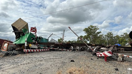
Source: ATSB
At about the same time as, or just prior to, the emergency call, the network controller located in Rockhampton, called Aurizon coal train 9F02 (travelling on the up line) via UHF radio about a loss of signalling detection at the points near the Bills Road level crossing. Around this time, the crew noticed a cloud of dust emanating from a train on the down line. The driver began to apply the emergency brake but collided with a container attached to a derailed wagon on train 82P7 fouling the up line. The train stopped short of the main wreckage of train 82P7, located at the Bills Road level crossing.
Train 9F02 sustained significant impact damage to the driver’s side of the cabin. Skidding impact damage was also evident along the side of the train (Figure 2).
Figure 2: Damage to leading locomotive of train 9F02
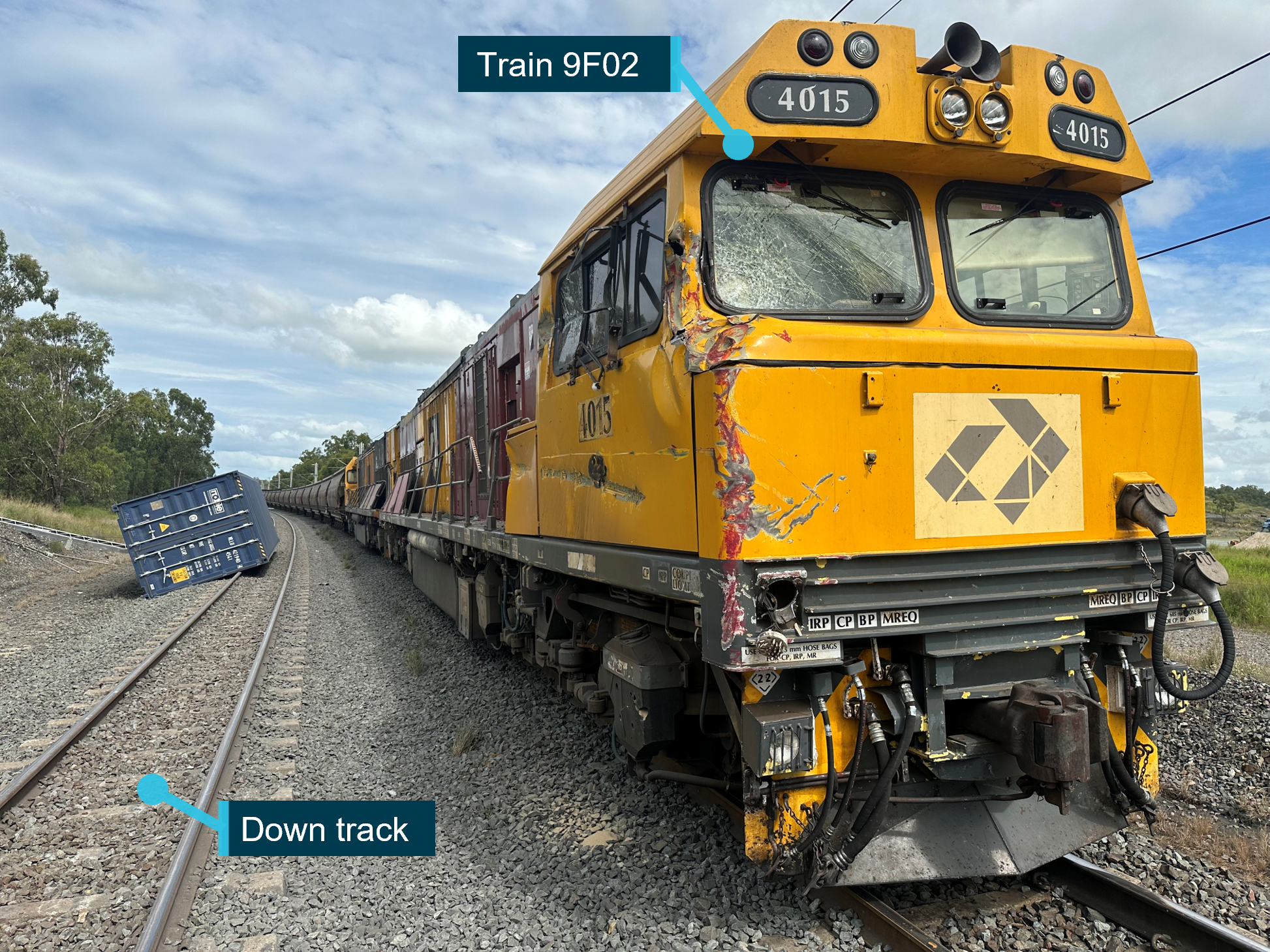
Source: ATSB
During on-site inspections, the ATSB found an axle from the sixth wagon (RNCY137-T) had fractured (Figure 3). This evidence correlated with rail wheel field-side[2] marks found on the rail head, identified as the point of derailment. The marks commenced on the field-side of the rail head and ran inwards towards the rail gauge face between both rails (Figure 4). There was no other evidence of derailment found on the approach to the point of derailment.
Figure 3: Damaged bogie showing half of the fractured axle half in-situ
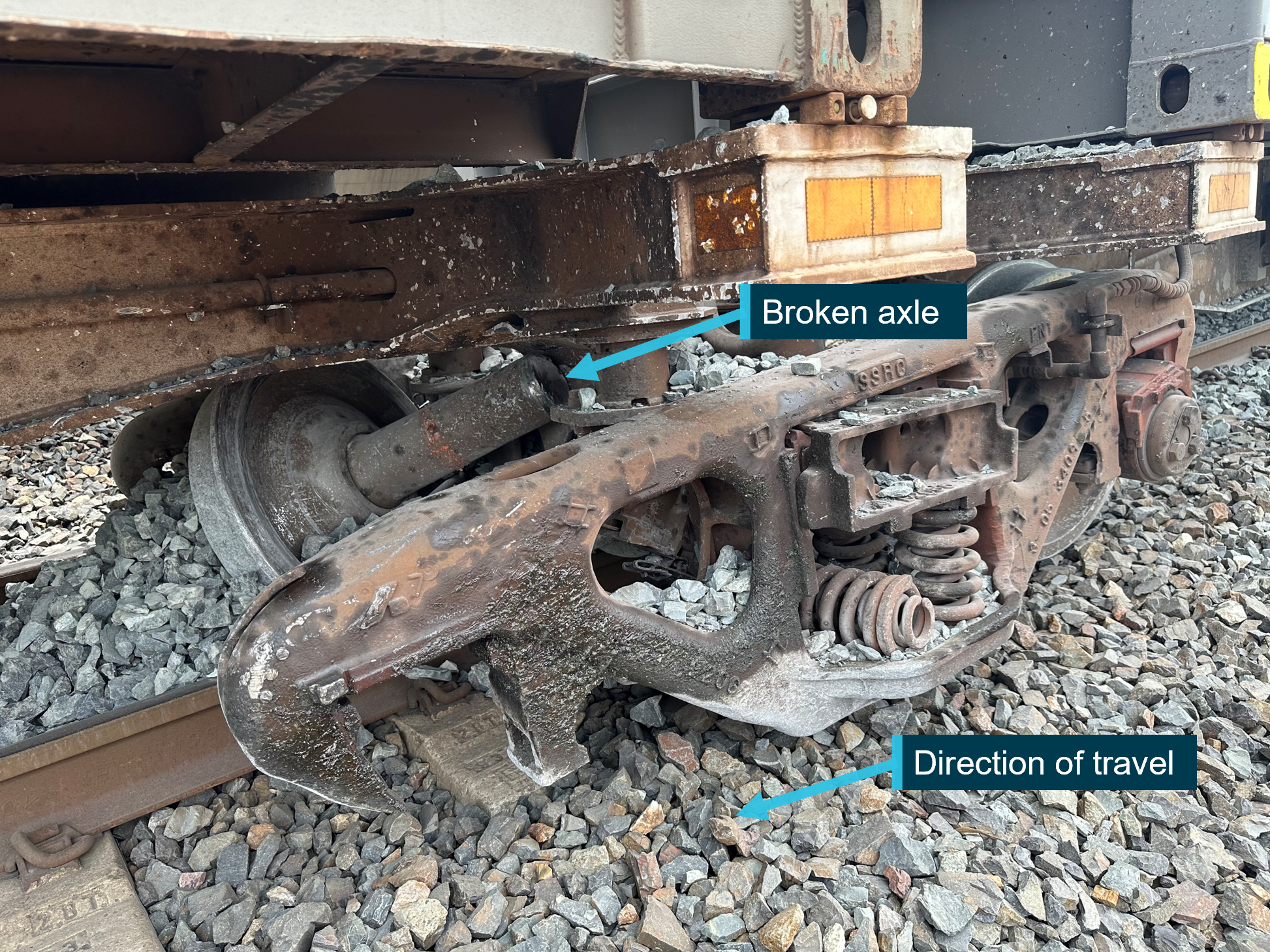
Source: ATSB
Figure 4: Wheel marks identified at the point of derailment
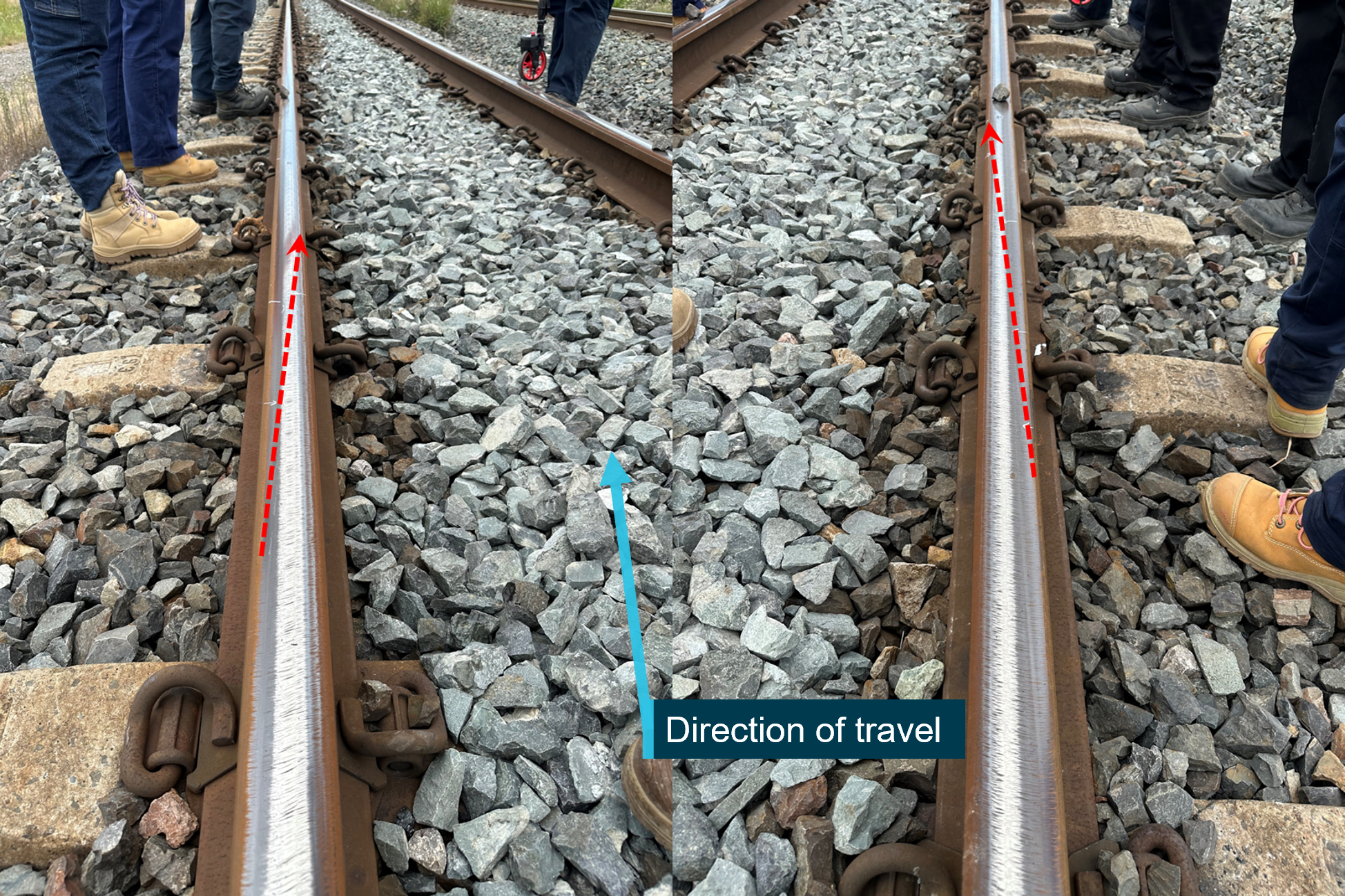
Source: ATSB
Further investigation
To date, the ATSB has:
- attended and completed site inspections
- interviewed the crew of both trains
- received evidential material including recorded data
- conducted a detailed examination of rolling stock components.
The investigation is continuing and will include:
- detailed material analysis of specific rolling stock components
- detailed examination of maintenance records, procedures, and practices
- similar occurrences
- other relevant evidential material.
Should a critical safety issue be identified during the course of the investigation, the ATSB will immediately notify relevant parties so appropriate and timely safety action can be taken.
A final report will be released at the conclusion of the investigation.
Purpose of safety investigationsThe objective of a safety investigation is to enhance transport safety. This is done through:
It is not a function of the ATSB to apportion blame or provide a means for determining liability. At the same time, an investigation report must include factual material of sufficient weight to support the analysis and findings. At all times the ATSB endeavours to balance the use of material that could imply adverse comment with the need to properly explain what happened, and why, in a fair and unbiased manner. The ATSB does not investigate for the purpose of taking administrative, regulatory or criminal action. TerminologyAn explanation of terminology used in ATSB investigation reports is available here. This includes terms such as occurrence, contributing factor, other factor that increased risk, and safety issue. Publishing informationReleased in accordance with section 25 of the Transport Safety Investigation Act 2003 Published by: Australian Transport Safety Bureau © Commonwealth of Australia 2023 
Ownership of intellectual property rights in this publication Unless otherwise noted, copyright (and any other intellectual property rights, if any) in this report publication is owned by the Commonwealth of Australia. Creative Commons licence With the exception of the Coat of Arms, ATSB logo, and photos and graphics in which a third party holds copyright, this publication is licensed under a Creative Commons Attribution 3.0 Australia licence. Creative Commons Attribution 3.0 Australia Licence is a standard form licence agreement that allows you to copy, distribute, transmit and adapt this publication provided that you attribute the work. The ATSB’s preference is that you attribute this publication (and any material sourced from it) using the following wording: Source: Australian Transport Safety Bureau Copyright in material obtained from other agencies, private individuals or organisations, belongs to those agencies, individuals or organisations. Where you wish to use their material, you will need to contact them directly. |
Occurrence summary
| Investigation number | RO-2023-001 |
|---|---|
| Occurrence date | 29/01/2023 |
| Occurrence time and timezone | 1910 Australian Eastern Standard Time |
| Location | 3 km east of Marmor |
| State | Queensland |
| Report release date | 30/06/2026 |
| Report status | Final |
| Investigation level | Systemic |
| Investigation type | Occurrence Investigation |
| Investigation phase | Final report: Dissemination |
| Investigation status | Completed |
| Mode of transport | Rail |
| Rail occurrence category | Collision, Derailment, Rolling Stock Irregularity |
| Occurrence class | Accident |
| Highest injury level | None |
Train details
| Train operator | Pacific National Pty Ltd |
|---|---|
| Train number | 82P7 |
| Track operator | Aurizon Network Pty Ltd |
| Type of operation | Intermodal containerised freight |
| Rail vehicle sector | Freight |
| Departure point | Moolabin Yard, Brisbane, Queensland |
| Destination | Townsville terminal, Queensland |
| Persons on board | Crew – 1, Passengers – Nil |
| Injuries | None |
| Train damage | Substantial |
Train details
| Train operator | Aurizon Operations Ltd |
|---|---|
| Train number | 9F02 |
| Track operator | Aurizon Network Pty Ltd |
| Type of operation | Coal/bulk |
| Rail vehicle sector | Freight |
| Departure point | Kabra, Queensland |
| Destination | Callemondah, Queensland |
| Persons on board | Crew – 2, Passengers – Nil |
| Injuries | None |
| Train damage | Substantial |