Occurrence Briefs are concise reports that detail the facts surrounding a transport safety occurrence, as received in the initial notification and any follow-up enquiries. They provide an opportunity to share safety messages in the absence of an investigation. Because occurrence briefs are not investigations under the Transport Safety Investigation Act 2003, the information in them is de-identified.
What happened
On 17 January 2026, the pilot and sole occupant of a Robinson R22 Beta II helicopter was conducting contracted stock mustering operations at a station, about 140 km north of Tennant Creek, Northern Territory. At about 0900 local time, the pilot refuelled the helicopter, filling the tanks to their capacity. Shortly after, they became airborne to continue with the mustering operation.
At about 0910, the pilot reported that while moving cattle through a gate, they conducted a right turn at about 35 kt and 120 ft above ground level. About 3 seconds after completing the turn, the pilot recalled hearing an unusual noise and suspected a possible bird strike with the tail rotor, perceiving no response to their anti-torque pedal inputs.
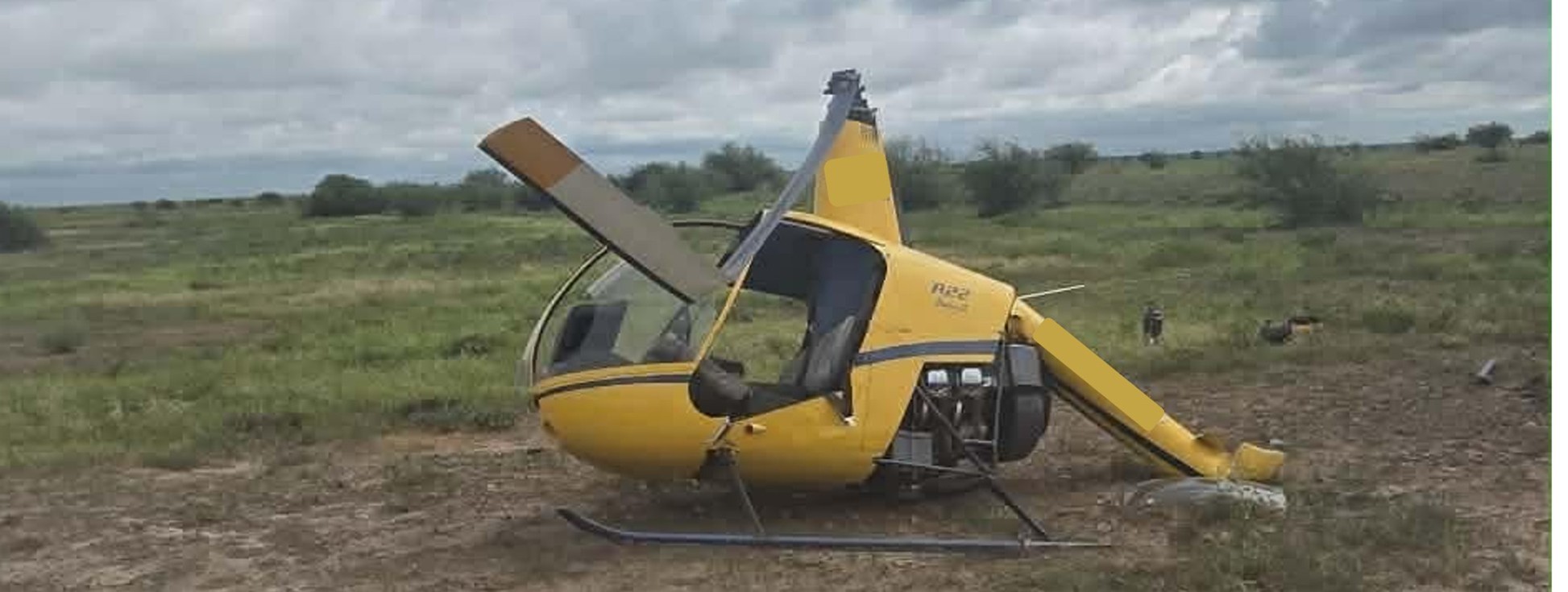
The pilot recalled that the low rotor RPM horn then sounded and the helicopter began to lose height. They reacted by lowering the collective in an attempt to regain the rotor RPM and attempted to gain forward airspeed. As the helicopter approached the ground the pilot flared and raised the collective[1] to reduce the rate of descent but the helicopter collided heavily with the terrain (Figure 1).
Figure 1: Occurrence helicopter
Source: Operator
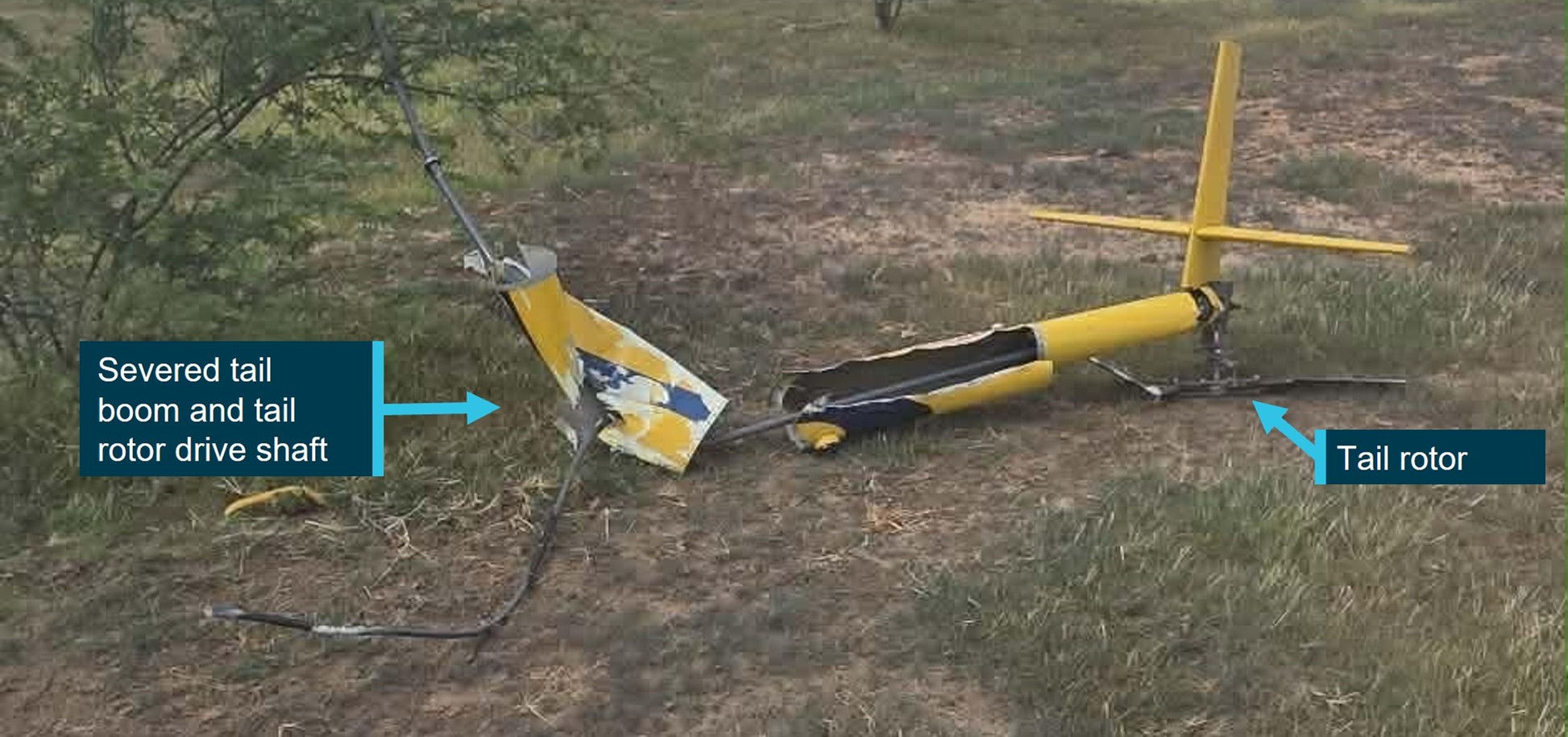
On contact with the ground, the helicopter’s main rotor blades flexed and contacted the tail boom causing it to separate. The tail boom, attached tail rotor gearbox and tail rotor were located about 30 m from the main wreckage (Figure 2).
Figure 2: Occurrence aircraft tail boom, and tail assembly
Source: Operator
The pilot wore a flight helmet and was restrained with a 3-point lap and sash harness and was able to free themselves from the wreckage uninjured. However, the helicopter was substantially damaged.
The operator conducted a post-accident engineering analysis of the wreckage and reported there were no indications of pre-impact defects or damage to the tail rotor flight control system that would have resulted in a loss of tail rotor control.
The operator advised that impact marks on the ground indicated that the helicopter was travelling in a west‑north-west direction when it impacted the ground and reported the wind direction at the time of the occurrence was 10–15 kt from the south-east, indicating that the helicopter was likely operating downwind when it impacted the terrain.
Following discussions with the pilot, the operator reported that additional weight after refuelling, combined with a loss of airspeed when turning downwind, likely led to the helicopter being overpitched. The operator considered that this likely caused a reduction in rotor RPM that was not immediately identified by the pilot. The loss of rotor RPM caused the helicopter to descend from a low height and the pilot was unable to recover the low rotor RPM or arrest the rate of descent prior to impacting the ground.
Additionally, the operator reported that the pilot had been listening to music during the low level operation, and identified that this may have reduced the pilot’s ability to aurally detect a reduction of the engine and rotor RPM prior to the low rotor RPM horn sounding. This may have reduced the pilot’s reaction and recovery time for a low rotor RPM condition. Robinson Helicopter’s Safety Notice 10 provides guidance on the recovery technique for low rotor RPM.
Safety action
The operator reported the following safety recommendations for company pilots:
not to turn the helicopter downwind while at low altitude
the importance of throttle control and to be aware of manually overriding the engine governor
awareness of the helicopters engine RPM and listening for audible cues
fuel load management and consideration given to all-up weight when conducting low-level flight.
Additionally, the operator advised that a notice was sent to all company pilots advising that listening to music while flying was not permitted, reiterating the importance of audible cues from the helicopter engine.
The operator’s safe work method statements required company pilots to wear flight helmets when conducting mustering operations. The use of flight helmets reduces the risk and severity of head injuries, especially important when conducting low-level and other higher risk flight operations.
Flight at low level is a necessity during mustering operations and often involves abrupt manoeuvres with frequent power changes. Although the R22 engine is equipped with a governor to maintain constant engine RPM, large abrupt power changes can cause the governor to lag, reducing engine RPM and therefore rotor RPM. Pilots, especially during periods of high workload, have been known to grip the throttle control tightly, overriding the governor and preventing the governor from maintaining a constant engine RPM. Operators who routinely conduct low level flight are encouraged to review their training and checking regarding engine RPM management as well as the recovery techniques from a low rotor RPM condition.
About this report
Decisions regarding whether to conduct an investigation, and the scope of an investigation, are based on many factors, including the level of safety benefit likely to be obtained from an investigation. For this occurrence, no investigation has been conducted and the ATSB did not verify the accuracy of the information. A brief description has been written using information supplied in the notification and any follow-up information in order to produce a short summary report, and allow for greater industry awareness of potential safety issues and possible safety actions.
[1]The collective control changes the pitch angle of all main rotor blades.
Occurrence summary
Mode of transport
Aviation
Occurrence ID
AB-2026-009
Occurrence date
17/01/2026
Location
140 km north of Tennant Creek
State
Northern Territory
Occurrence class
Accident
Aviation occurrence category
Collision with terrain, Control - Other, Loss of control
On 1 November 2017, an Aeroprakt A22LS Foxbat was involved in a landing accident that resulted in the aircraft coming to rest inverted adjacent to the airstrip. Examination of the aircraft following the occurrence, identified that the right rudder control cable had failed in flight. Significant damage to the left rudder control cable was also identified at a similar location to where the right cable had failed.
Recreational Aviation Australia requested that the ATSB perform a detailed technical examination of the aircraft’s rudder control cables and associated rigging. The scope of this examination was limited to the identification of factors that contributed to the damage and subsequent failure of the cable. To facilitate this work, the ATSB initiated an external investigation under the Transport Safety Investigation Act 2003.
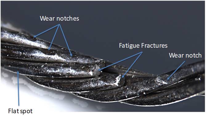
The ATSB analysis found that the right cable failed as a result of fatigue failure associated with significant wear of the individual wires (see Figure 1). Although the left hand cable did not fail, it was found to be unserviceable based on the standards set in the aircraft maintenance manual, due to fatigue fracturing of the wire strands. Both cables were found to be within material specifications.
Figure 1: Wear and associated fatigue fracture of wires on the right rudder control cable
Source: ATSB
Any further enquiries in relation to the accident investigation should be directed to Recreational Aviation Australia.
___________ The information contained in this update is released in accordance with section 25 of the Transport Safety Investigation Act 2003.
On 25 September 2015, a Cessna 550 aircraft (Citation Bravo), registered VH-FGK, taxied at Lismore Airport for a private flight to Baryulgil, New South Wales. The flight crew consisted of a captain and copilot, who were the only occupants of the aircraft.
The flight crew did not detect anything abnormal during the taxi and take-off roll, until the captain attempted to rotate the aircraft to the take-off pitch attitude. When the aircraft had achieved the required rotate speed, the captain applied the normal backpressure on the control column to achieve a standard rate of rotation, and the aircraft did not rotate. The captain then applied full backpressure and reported that the controls felt very heavy. Neither the captain nor the copilot detected any change in the aircraft’s pitch attitude or any indication of pitch-up on the attitude direction indicator.
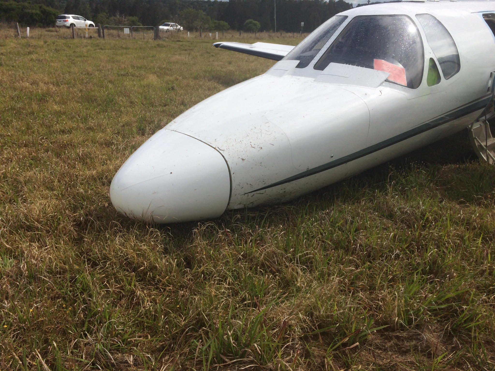
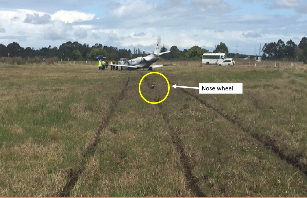
The captain rejected the take-off, applied full braking and reverse thrust, but the aircraft overran the runway. The nose landing gear detached from the aircraft about 50 m beyond the end of the sealed runway, and the aircraft came to rest in long grass and mud. The aircraft sustained substantial damage, and the captain and copilot were uninjured.
What the ATSB found
The aircraft did not accelerate normally as the acceleration was retarded by drag associated with rolling friction. This was indicative of partial brake pressure remaining during the take-off run. The partial brake pressure was possibly due to the parking brake being selected on at the holding point with enough pressure to retard aircraft acceleration during the take-off, but not sufficient to prevent the aircraft reaching rotate speed.
Furthermore, the nose-down moment generated by the partial brake pressure probably prevented the aircraft rotating sufficiently to become airborne, despite normal nose-up elevator deflection.
Heat in the brakes due to partial pressure during the take-off run may have reduced their effectiveness when the captain rejected the take-off, contributing to the runway overrun.
What has been done as a result
The Australian Transport Safety Bureau issued a safety recommendation that Textron Aviation (Cessna) take safety action to address the fact that Citation aircraft do not have an annunciator light to show that the parking brake is engaged and the Cessna 'before take-off' checklist does not include a check to ensure the parking brake is disengaged.
Safety message
For pilots, this incident highlights the importance of attention to the configuration of the aircraft and cockpit settings at all stages of flight, but particularly during take-off. For manufacturers, this incident highlights the importance of systems that bring an irregular or abnormal configuration or cockpit setting to the attention of the crew, especially when that configuration has the potential to adversely affect aircraft performance or control.
Accident site of Cessna 550 aircraft (Citation Bravo), registered VH-FGK, at Lismore Airport
Source: Aircraft operator
The occurrence
History of the flight
On the morning of 25 September 2015, the captain and copilot of a Cessna 550 aircraft (Citation Bravo), registered VH-FGK, prepared to conduct a private flight from Lismore Airport to Baryulgil, about 40 NM south-west of Lismore, New South Wales. The aircraft had been parked at the northern end of the airport overnight, with engine covers and control locks on.
After arriving at the airport, the flight crew conducted a pre-flight inspection, with no abnormalities identified. They then commenced the normal pre-start checks, which included the disengagement of the flight control locks.
The crew elected to use runway 15 for take-off, and used the Cessna simplified take-off performance criteria (see Take-off performance simplified criteria) to determine the thrust settings and take-off reference speeds. The resultant reference speeds were 105 kt for the decision speed (V1)[1] and 108 kt for the rotation speed (VR).[2]
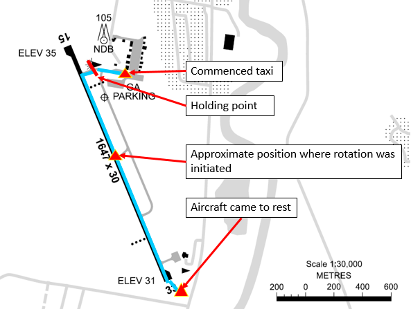
At about 1300 Eastern Standard Time,[3] the flight crew started the engines and performed the associated checks, with all indications normal. The crew reported that they completed the after-start checks, and the captain then taxied the aircraft to the holding point for runway 15, less than 200 m from where the aircraft was parked (Figure 1). While stopped at the holding point, the crew completed the taxi and pre-take-off checks, the copilot broadcast the standard calls on the common traffic advisory frequency, and the captain communicated with air traffic control (ATC).
Figure 1: Lismore Airport showing aircraft track
Source: Airservices Australia – annotated by ATSB
The captain taxied the aircraft onto the runway, and turned left onto the runway centreline to commence the take-off run from the intersection (Figure 1). While rolling along the runway, the captain advanced the thrust levers to the approximate take-off setting. The captain then called ‘set thrust’, and the copilot set the thrust levers to the more precise position needed to achieve the planned engine thrust for the take-off.
As the aircraft accelerated, the copilot called ‘80 knots’ and crosschecked the two airspeed indicators were in agreement and reading 80 kt. The copilot called ‘V1’ and the captain moved their hands from the thrust levers to the control column in accordance with the operator’s normal procedure. A few seconds later, the copilot called ‘rotate’ and the captain initiated a normal rotate action on the control column.
The crew reported that the aircraft did not rotate and that they did not feel any indication that the aircraft would lift off. The copilot looked outside and did not detect any change in the aircraft’s attitude as would normally occur at that stage. The captain stated to the copilot that the aircraft would not rotate, and pulled back harder on the control column. The copilot looked across and saw the captain had pulled the control column firmly into their stomach.
Although the aircraft’s speed was then about 112 kt, and above VR, the crew did not detect any movement of the attitude director indicator or the nose wheel lifting off the ground, so the captain rejected the take-off; applied full brakes, and set the thrust levers to idle and then into reverse thrust.
The aircraft continued to the end of the sealed runway and onto the grass in the runway end safety area (RESA), coming to rest slightly left of the extended centreline, about 100 m beyond the end of the runway (Figure 2).
Figure 2: Accident site
Source: Lismore City Council – annotated by ATSB
Injuries and damage
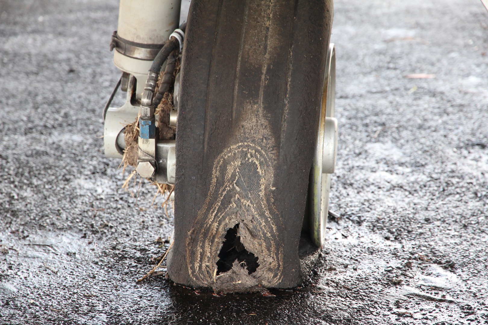
The aircraft sustained substantial damage and the flight crew, who were the only occupants of the aircraft, were uninjured. The nose landing gear separated from the aircraft during the overrun (Figure 2), and there was significant structural damage to the fuselage and wings. The right wheel tyre had deflated due to an apparent wheel lockup and flat spot, which had progressed to a point that a large hole had been worn in the tyre (Figure 3).
Both flight crewmembers were appropriately trained and qualified for the flight, and reported feeling well rested and healthy.
Captain
The captain held an Airline Transport Pilot (Aeroplane) Licence, command instrument rating and a valid Class 1 medical certificate. The captain had a total aeronautical experience of 5,937.7 hours, including 800.6 hours on Citation aircraft, and also had check and training approval for the Citation.
Copilot
The copilot held a Commercial Pilot (Aeroplane) Licence, command instrument rating and a valid Class 1 medical certificate. The copilot had a total aeronautical experience of 377.8 hours, including 40.4 hours on Citation aircraft.
Aircraft information
Weight and balance
There were two crewmembers on board and no passengers. The crew reported that each pilot had a small bag stowed in the nose locker and there was no additional baggage on the aircraft. According to the loadsheet for the flight, there was about 4,000 lb (1,814 kg) of fuel on board (full fuel was 4,871 lb (2,214 kg)), and the take-off weight was about 13,518 lb (6,132 kg), below the maximum take-off weight of 14,800 lb (6,713 kg).
The crew reported they completed the weight and balance calculations prior to the flight, in accordance with their normal procedures. The load sheet obtained by the ATSB showed that the centre of gravity was within the allowable range.
Aircraft examination
The operator’s engineering manager inspected the aircraft on 1 October 2015, for any mechanical reason for the reported lack of response to elevator control input. The maintainer reported that the elevators were able to be operated to full deflection to the mechanical travel stops from the cockpit in the up and down sense. There was no binding or restrictions to travel noted in around the control yoke in the cockpit. There was no external evidence on or in the vicinity of the elevators to cause any restriction to travel.
The aircraft owner, who also inspected the accident site, reported that:
the nose locker was filled with water and mud,
the control lock could not be bypassed (that is, was working correctly),
the weight and balance was towards the middle of the allowable envelope, and
the elevator controls and surfaces had full deflection and were able to be moved in the correct sense.
The ATSB inspected the aircraft on 4 November 2015, after it had been moved to a hangar. The aircraft examination was limited to external general observations and a detailed examination of the flight control lock and elevator and trim systems, in an attempt to ascertain the reasons for an apparent lack of elevator response during the incident.
The control lock, elevator and trim system were in good mechanical order. All functional checks, tests and examinations did not find a fault that may have contributed to the runway overrun.
The left brake had been removed during the recovery of the aircraft as the brake had seized due to overheating (see Brakes).
Airspeed indications
The aircraft was equipped with three separate and independent pitot-static systems. The two primary systems served the captain’s and copilot’s systems. The third provided pitot and static air pressure to the standby flight display. Altitude and airspeed data was generated by micro air data computers, which transmitted the information to the primary flight displays. With two independent sources, and the copilot verifying at 80 kt that both airspeed indicators were in agreement, it is unlikely that they were both indicating the same but incorrect airspeed. Available evidence suggests that the airspeed indicating system was functioning normally during the take-off.
Thrust
The flight data and crew reports indicated that the thrust was set in accordance with the settings indicated in the simplified take-off performance reference. Both crew reported engine indications were normal. The flight data showed the engine RPM was consistent with four previous flights.
The flight data shows that the engines were delivering the expected amount of thrust during the take-off, and reverse thrust was not selected until after the captain rejected the take-off.
Elevator deflection and control movement
The captain checked the flight controls as part of the pre-take-off checks, and verified full and free movement, and normal feel of the control column. The crew were unable to see the elevator to assess whether control movement matched control surface deflection, however, normal deflection was evident in the recorded flight data.
The crew stated that the captain pulled the control column as far back as possible during the take-off roll, but that the aircraft did not rotate. The flight data showed that the elevator achieved normal deflection in the correct sense in response to the control input. The elevator was also operating correctly immediately after the accident when the operator’s engineer inspected it, and when the ATSB subsequently inspected the full length of the elevator system.
Therefore, it can be concluded that the control input resulted in a correct and normal elevator deflection.
Aircraft configuration
From the available evidence, the following were configured correctly for the take-off:
There was no evidence of any external securing articles still in place at the time of the accident. The post-accident inspection did not find any such articles. The crew reported having completed a normal pre-flight external inspection. There was no indication in the flight data of aerodynamic drag from, for example, an unsecured panel.
The control lock was released. The aircraft will not start without the control lock being released, as it locks the thrust levers. The control lock mechanism was subsequently found to be working correctly and therefore would have prevented the pilot from starting the engines if it had been left in place.
Based on the crew reports, cockpit voice recording and photo of the cockpit centre console immediately after the accident, the elevator trim was set correctly for take-off – in the take-off position marked on the trim indicator.
The flight data showed that the speed brakes were not deployed.
The flight data showed the autopilot was not engaged.
The crew reported that the flaps were set in the ‘take-off/approach’ position marked on the flap indicator. The flight data was consistent with the flaps being set for take-off.
Based on the cockpit voice recording, the crew completed all after-start, taxi and pre-flight checks in the sequence of the published aircraft checklist. The captain’s response to the copilot’s call of ‘brakes’ during the after-start checks was ‘I’ll check them’. There was no subsequent reference to the brake check on the CVR, however, the required action was to apply the toe brakes and ensure symmetrical retardation and positive pressure existed.
Aircraft parking brake
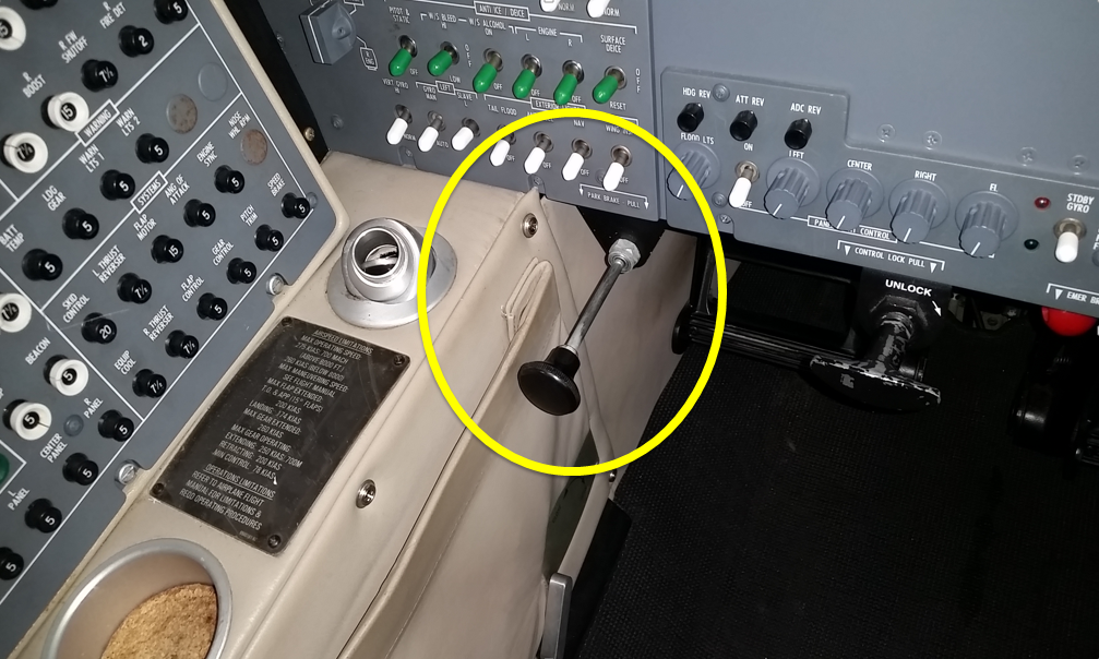
The parking brake was set by either pilot applying and holding footbrake pressure and the pilot in the left (captain’s) seat pulling out the parking brake lever underneath the left instrument panel (Figure 4). The lever could be selected OFF or fully ON. There was no partial release position of the lever. When the lever was pushed forward from the ON position, pressure in the lever would continue to release the lever until it was in the OFF position. The position of the parking brake lever was not visible to the pilot in the right seat. There was no cockpit annunciation that the parking brake lever was in the ON position.
Figure 4: Parking brake lever in the ON position
Source: Aircraft owner
With the parking brake on, the applied pressure in the brake lines is trapped, and when the footbrake is released, the pressure at the brakes remains. If the parking brake handle is pulled with no footbrake pressure applied, no pressure will be present in the brakes. However, any subsequent footbrake pressure will be trapped and maintained, until the parking brake lever is returned to the OFF position. The park brake is certified to ensure that with full pressure applied, the wheels will remain locked even if full thrust is applied on both engines.
The parking brake was found engaged following the accident. However, the captain reported engaging it after the aircraft came to rest in the grass. The captain also reported that evacuation training always included setting the park brake as one of the first actions. The captain could not recall selecting the parking brake ON while at the holding point, where the aircraft was stationary for over 4 minutes.
Brakes
The aircraft brakes consisted of alternating discs connected to the wheel and axle. When the brakes are applied when the wheels are moving, their temperature will rise. If the brakes overheat, the disc pack will seize and the wheel will stop rotating. The brakes incorporated an anti-skid system. When a skid or impending locked wheel condition is sensed, a signal is sent to release the pressure in the affected brake.
After the accident, the left brake had seized and both brakes appeared to have been exposed to very high temperatures.
If the brakes were partially engaged while the aircraft was moving throughout the take-off run, they would have been absorbing energy and increasing in temperature. In the event of a rejected take-off, the brakes would then be less effective than usual due to their elevated temperature.
The operator’s engineering manager who inspected the accident site reported that they were unable to inspect the brakes as the brake and wheels were packed solid with grass and mud, and one tyre was fully deflated. The engineering inspection report provided to the ATSB (see Aircraft examination above) was limited to the elevator control functionality.
A failure of the parking brake valve could result in partial brake pressure. The brake valve was not inspected after the accident by the operator nor assessed during the ATSB’s inspection of the aircraft. However, as the braking system was working during the taxi to the holding position, the short time between holding to enter the runway and taxiing onto the runway was the only opportunity for it to fail. Further, a senior air safety investigator from Textron Aviation (Cessna) was unaware of any other failures of the valve to operate correctly.
Airport information
Runway
Runway 15 at Lismore had an available take-off length of 1,647 m (5,403 ft). The runway sloped down by 0.1 per cent. The aircraft was taxied onto the runway at the northern taxiway intersection, about 152 m (500 ft) beyond the runway threshold (Figure 1). Although the take-off was commenced from the intersection, an additional 152 m of runway was available to the crew for the take-off.
Runway end safety area
The Civil Aviation Safety Authority Regulation (CASR) 139 Manual of Standardsrequires Code 3 and 4 runways[4] like runway 15 at Lismore to have a runway strip extending 60 m beyond the runway end, and a runway end safety area (RESA) for 90 m beyond the runway strip. In addition, the International Civil Aviation Organization Annex 14 recommends that the RESA should extend (as far as is practicable) to a length of at least 240 m beyond the end of the runway strip.
Runway strips consist of a fully graded area surrounding the runway at both ends and beyond the side of the runway. Runway strips are required by CASR 139 to be free of all fixed objects and potential obstructions, other than visual aids for guiding aircraft or vehicles. These objects must be of low mass and frangible. The aim of this area is to reduce the risk of damage to aircraft running off the ends or sides of the runway.
RESAs are areas of graded flat ground beyond the end of a runway and runway strip, designed to enhance aircraft deceleration. These are symmetrical about the extended runway centreline, and are free from any non-frangible obstacles or obstructions.
By assisting aircraft to decelerate in a controlled manner, RESAs are designed to reduce the risk of damage to an aircraft that undershoots the runway, rejects a take-off and overruns the runway end, or overruns the runway end following a landing.
Using measurements from a Google Earth image of Lismore Airport taken in 2014, the overrun area beyond the sealed end of runway 15 at Lismore was about 180 m to the airport boundary fence, flat, grassed and free of obstacles.
Accident site
Similarly, using measurements from Google Earth based on photos of the accident site, the aircraft came to rest about 150 m beyond the sealed runway and before the airport boundary fence. The RESA at Lismore may have assisted in decelerating the aircraft after the rejected take-off and reduced risk of injury and damage to the aircraft.
Distinctive marks on the end of runway 15 indicated that the right wheel tyre had deflated after the captain rejected the take-off and the wheel’s rim was making contact with the runway. The position of the tyre witness marks on the runway showed that the aircraft remained just to the right of the centreline but moving towards the left as it exited the runway (Figure 5).
Figure 5: Southeast end of the runway showing right wheel contact marks on the runway and their position in relation to the runway centre line
Source: Aircraft owner
Operational information
Weather
According to the Meteorological Terminal Aviation Routine Weather Report (METAR) for Lismore Airport issued at 1230, the wind was from 190° at 10 kt, and the temperature was 18 °C. The runway was dry at the time of the accident.
Take-off performance simplified criteria
The Cessna 550 pilot operating handbook specified values for speeds and power settings for a reduced thrust take-off, known as simplified take-off performance criteria. The simplified criteria could only be used if the following conditions were met, including:
flaps set to 15° (take-off and approach setting)
available take-off field length of 5,200 ft (1,585 m) or longer
no tailwind
no runway gradient
dry paved runway.
The crew used the reduced-thrust reference speeds and power setting based on an aircraft weight of 14,000 lb (6,350 kg) or less, airport altitude 3,000 ft or below, and the ambient temperature between -1 °C and 35 °C.
The aircraft weight, airport altitude and temperature met the required criteria, and the flaps were recorded in a position suitable for take-off and consistent with the simplified take-off criteria. In addition, by commencing the take-off run from the taxiway intersection, the runway length remaining (4,900 ft) was about 300 ft (91 m) less than that required.
Flight data
Accident flight
The ATSB analysis of the flight data recorder (FDR) showed:
the control column input (to rotate the aircraft) started at about 105 kt (which was the calculated V1; VR was 108 kt)
the maximum elevator position of 11° occurred at about 111 kt
the maximum pitch attitude of 4.7° occurred at about 112 kt
the aircraft took about 19 seconds to accelerate from 40 kt to 110 kt.
Flight data comparison
The accident flight data was compared with four previous flights. Although numerous variables would have differed for each of the previous flights, such as aircraft weight and balance and environmental conditions, the difference in the take-off run data between those flights was not significant compared with the evident differences in the data from the accident flight. Although the engine RPM was not significantly different from the previous flights, the accident flight differed to the others in the following ways:
For the accident flight, the aircraft took about 19 seconds to accelerate from 40 to 110 kt, or almost twice that of the previous four flights, which took 10-12 seconds.
While the rate of change of the elevator deflection after VR was similar to four previous flight, the total deflection was greater.
The rate of change of aircraft pitch after VR was significantly lower (1.6° per second) than previous flights (3.6-4.8° per second). The maximum pitch angle was 4.7° whereas for the previous flights it was about 11°.
Analysis of flight data
During the take-off run, the aircraft accelerates against the aerodynamic drag of the aircraft and rolling resistance of the wheels. The variations of these with speed[5] are different. The aerodynamic drag increases with the square of speed. In contrast, principal components of the rolling resistance are a constant force that varies with rolling speed. As shown in Appendix A, removing a component of aerodynamic drag to the accident flight speed profile does not result in a similar speed profile to the previous four flights throughout the take-off run. However, correcting the acceleration at a constant rate of 2.5 kt/sec does result in a closely correlated speed profile with the previous four flights. As such, it is evident the slow acceleration was a product of additional rolling resistance of the wheels rather than additional aerodynamic drag.
Appendix A also shows that an additional rolling resistance on the wheels, given the aircraft’s thrust line (engine height) was above the main wheels contact point with the runway, would create a nose-down moment on the aircraft. Full elevator deflection, at the thrust setting and the airspeed when the captain attempted to rotate the aircraft, would have been insufficient to overcome this nose-down moment. (Aerodynamic drag would not produce the nose-down moment preventing rotation.)
Similar incidents
In 2010, a Cessna Citation CJ1, registered N646VP, overran the runway at Leeds Bradford Airport, West Yorkshire, UK. During the take-off run, the pilot assessed that the aircraft would not accelerate to V1 and rejected the take-off. As the pilot braked, both brakes failed, the right brake caught fire and the aircraft overran the end of the runway. The accident investigation by the UK Air Accident Investigation Branch (AAIB), and reported in AAIB bulletin 3/2011, concluded that the brakes were probably on, at least partially, during the take-off run.
The US National Aeronautics and Space Administration (NASA) provided the ATSB with a report of Cessna Citation parking brake engaged or partially engaged during takeoff roll incidents from the Aviation Safety Reporting System (ASRS).[6] This included the following two (of three) reports:
A Cessna 525 owner/pilot reports hiring a professional pilot to fly him to an airport due to a strong gusty wind forecast. The professional pilot forgets to release the parking brake prior to takeoff and this omission is not detected until airborne. Upon landing the right brake is locked and the right tire fails causing directional control problems.
On landing, a Cessna 550 blew both main tires which was caused by a partially engaged parking brake. There is no warning system or light that indicates the parking brake is still engaged.
A Senior Investigator from Textron Aviation (Cessna) indicated that there have been similar events where pilots have attempted to take off with the parking brake set and enough pressure to keep the aircraft rolling at idle thrust, resulting in similar incidents. This led to the publication of an article in Cessna’s Direct Approach magazine issued in December 2008, which reminded operators to make sure to disengage the parking brake.
There is no parking brake indicator to alert the flight crew that the park brake handle is engaged. Flight crews should follow the procedures in the Airplane Flight Manual (AFM) and the Pilots’ Abbreviated Checklist regarding the brake system operation. The pilot in command is the last set of eyes to make certain the brake system switch, circuit breaker, and park brake are all in the correct positions before taxi or takeoff.
While the crew did not detect anything abnormal during the take-off run until rotation, the flight data showed a significantly reduced acceleration despite normal thrust and engine RPM, and normal aircraft configuration. When the captain attempted to rotate the aircraft, the aircraft did not rotate despite full elevator deflection. The captain rejected the take-off, applying full brakes and reverse thrust. Before the aircraft could stop, it overran the runway onto the grass over-run area, which minimised damage to the aircraft and prevented serious injuries occurring.
There was no evidence that the slow acceleration was related to aircraft weights or balance, weight and balance calculations, aircraft configuration or thrust settings, or inaccurate airspeed readings. There was also no evidence to suggest that the lack of rotation was related to insufficient elevator deflection or control column movement, external locks, control locks, inappropriate elevator trim, or inappropriate airspeed.
Flight data analysis showed that the slow acceleration and lack of rotation at VR was consistent with a constant rolling resistance on the wheels. The analysis will consider the possibility that this rolling resistance was a result of partial brake pressure on the wheels as a result of an engaged parking brake. It will look at the limited opportunities the crew have to detect an engaged parking brake when it results in only a small amount of brake pressure. The analysis will also examine the implications of the captain’s late take-off rejection and the intersection departure, and the runway end safety area, on the safety of flight.
Partial brake pressure during take-off
Rolling resistance on the wheels could be a result of a number of factors, such as soft ground, a wheel, tyre or brake failure, or partially applied braking pressure to the wheels.
The runway was a sealed hard surface, so it is not feasible the surface had any effect.
Neither crew member detected any tendency for the aircraft to yaw. Additionally, the position of the tyre witness marks on the runway showed that the aircraft remained on the runway centreline until after the captain rejected the take-off. This is indicative of equal resistance from both main wheels and not a failure of one wheel, brake or tyre.
Given that only one tyre was damaged (and that witness marks indicate it was damaged after the rejected take-off), it is therefore probable that the rolling resistance experienced by the aircraft was a result of partial brake pressure in both wheels. This affected both the slow acceleration rate and inability to rotate the aircraft at VR.
Previous incidents have also shown that partial brake pressure in the wheels can lead to slow acceleration and an inability to rotate during take-off.
Parking brake not disengaged
The partial brake pressure to both wheels could have been a result of one of the flight crew applying toe braking throughout the take-off, a mechanical failure of the parking brake valve, or an engaged parking brake.
Both crew were sufficiently experienced to make it very unlikely that either was accidently applying toe braking during the take-off run. Furthermore, the copilot (as pilot monitoring) reported having their feet flat on the floor during the take-off.
The possibility of mechanical failure of the parking brake valve was unlikely. The crew had been able to release the parking brake and commence taxiing to the holding point, and confirmed pressure was achievable in the toe brakes during the taxi. Although they were not inspected after the accident, there was very limited opportunity for them to fail (after leaving the holding point), and there was no evidence of failure or history of failures of the park brake valve in other Cessna Citation aircraft.
In order for partial braking pressure to exist in the wheel as a result of the parking brake lever not being disengaged, a small amount of pressure from toe braking would also need to have been trapped.
The captain could not recall whether they selected the parking brake on while at the holding point. The aircraft was stationary at the holding point for over 4 minutes. The captain reported that only light pressure on the toe brakes would have been necessary to stop the aircraft at the holding point with the engine thrust at idle and after a short taxi. This would be consistent with enough partial pressure remaining in the brakes to affect acceleration but not sufficient to prevent the aircraft reaching VR.
The parking brake was found engaged following the accident. The captain reported they engaged it after the aircraft came to rest in the grass. However, it is possible that having observed the parking brake engaged on returning to the aircraft after exiting following the accident, and expectations based on evacuation training, the captain may have assumed they engaged it during the shutdown process, influencing their subsequent memory. The flight crew reported being quite shocked and in a hurry to exit the aircraft in case of fire following the accident, and the CVR showed that the copilot needed to remind the captain to complete another pre-evacuation action (shutting down the engines). The copilot was unable to see the parking brake lever from their position.
The aircraft manufacturer was aware of a number of events where pilots have attempted to take off with the parking brake on and just enough pressure remaining in the brakes to permit the aircraft to roll even at idle thrust. These have resulted in similar incidents, including a runway overrun involving a Cessna Citation CJ1 (with the same braking system) in 2010 in the UK. Further, the captain, aircraft operator and owner, and Cessna, have all reported that it is not uncommon to attempt to taxi the Citation aircraft with the park brake engaged.
Therefore, although there is no direct indication that the parking brake was engaged resulting in a small amount of pressure being trapped in the brakes, the plausibility of it, past occurrences where it has occurred, and the absence of other explanations given the evidence suggests it is probable that the parking brake was still engaged during the take-off run.
No related cockpit annunciation or checklist item
The park brake lever was the only indication that the park brake was engaged in Cessna Citation aircraft. However, the lever is on the captain’s side and is not visible from the copilot’s seat. Further, it is outside the captain’s normal line of sight during a routine instrument scan.
There was no cockpit annunciation on the instrument panel to show that the parking brake was on, and there was no check that the parking brake in the (manufacturer supplied) aircraft’s pre-take-off checklist. The lack of one of either the annunciator light or a checklist item makes it difficult for any crew to realise when the parking brake is inadvertently left engaged when only partial brake pressure exists.
A representative from Textron Aviation (Cessna) advised that they were aware of similar events occurring due to pilots attempting to take off with the parking brake set, and only enough pressure to allow the aircraft to keep rolling at idle thrust. Cessna’s Direct Action magazine had published a reminder to operators of Citation aircraft to ensure the parking brake was disengaged in response to a previous similar incident. The article stated ‘There is no parking brake indicator to alert the flight crew that the park brake handle is engaged’.
Given the position of the park brake lever, the lack of annunciator light on the instrument panel, and no pre-take-off check, in addition to the fact that the slow acceleration was not perceivable to the crew, made it almost impossible for the crew to discover that the parking brake was engaged.
Rejected take-off and overrun
Following the reduced acceleration during the take-off run, the aircraft accelerated to VR but did not rotate, so the captain rejected the take-off.
When the aircraft reached VR, the captain initiated rotation with normal backpressure (for a 3 degree per second rotation) on the controls. The captain reported that the controls felt heavy, and the aircraft did not rotate. The captain then applied full backpressure on the controls, and neither crew member detected any indication that the aircraft had pitched up, or that it would become airborne. The heavy feel of the control column and lack of rotation led the captain to assess that the aircraft was not capable of flight, and with the end of the runway looming, the captain rejected the take-off above critical speed.
The captain rejected the take-off, applying full brakes and reverse thrust. Partial pressure in the brakes during the take-off run would have overheated the brakes, reducing their effectiveness in the rejected take-off. Once the right tyre had blown, braking action would have been further compromised. The reduced acceleration during the take-off run meant the aircraft was further down the runway than normal when the aircraft reached VR. Combined with the reduced braking effectiveness, the aircraft could not stop on the runway.
Rejecting the take-off despite the aircraft exceeding V1 (after assessing the aircraft was not capable of flight) was in accordance with the operator’s standard pre-take-off safety brief. The captain did not attempt to increase thrust (to try to get airborne) when the aircraft failed to rotate. If the captain had increased thrust, the aircraft may have achieved a sufficient speed to become airborne despite little or no rotation. However, the captain could not be certain of this. The decision to reject the take-off at this late stage resulted in the runway overrun, but reduced the overall risk to the flight compared to the potential for catastrophic damage and injury if the aircraft failed to achieve adequate lift, or achieved a successful take-off followed by a landing with partial brake pressure, ineffective brakes and a strong nose-down moment.
Intersection departure
The flight crew conducted an intersection departure with reduced thrust without realising the runway remaining was 300 ft (91 m) less than the 5,200 ft (1,584 m) stipulated in the simplified reduced thrust take-off criteria. The crew elected to commence the take-off from the taxiway intersection reducing the available runway length by about 500 ft (150 m).
Use of the full runway length may have reduced the distance the aircraft overran the runway by, however, the flight data indicated that the aircraft was still travelling at about 77 kt when it ran off the end of the sealed runway, and therefore that significant deceleration occurred due to the wet grass and mud in the runway overrun area. Therefore, it is unlikely that the use of the full runway would have prevented the runway overrun in this case.
By not realising the simplified criteria did not apply to the runway length available when using an intersection departure, the crew were increasing risk of a runway overrun if they rejected the take-off at about V1.
Runway end safety areas
The grass overrun area beyond the sealed end of runway 15 at Lismore was about 180 m to the airport boundary fence, longer than the required 150 m (90 m runway end safety area extending beyond the 60 m runway strip), and contained the aircraft which came to rest about 150 m beyond the end of the runway. The suitable overrun area restricted the aircraft damage and resulted in no injuries resulted from the accident.
Findings
From the evidence available, the following findings are made with respect to the runway excursion involving a Cessna 550, VH-FGK, at Lismore Airport, New South Wales, on 25 September 2015. These findings should not be read as apportioning blame or liability to any particular organisation or individual.
Safety issues, or system problems, are highlighted in bold to emphasise their importance. A safety issue is an event or condition that increases safety risk and (a) can reasonably be regarded as having the potential to adversely affect the safety of future operations, and (b) is a characteristic of an organisation or a system, rather than a characteristic of a specific individual, or characteristic of an operating environment at a specific point in time.
Contributing factors
There was probably residual braking pressure in the wheel brakes during the take-off run.
The aircraft’s parking brake was probably applied while at the holding point and not disengaged before taxing onto the runway for take-off.
The Citation aircraft did not have an annunciator light to show that the parking brake is engaged, and the manufacturer’s before take-off checklist did not include a check to ensure the parking brake is disengaged. [Safety issue]
The aircraft experienced a retarded acceleration during the take-off run, and did not rotate as normal when the appropriate rotate speed was reached, resulting in a critical rejected take-off and a runway overrun.
Other factors that increased risk
The flight crew conducted an intersection departure with reduced thrust without realising the runway remaining was 300 ft (91 m) less than the 5,200 ft (1,585 m) stipulated in the 'simplified reduced thrust take-off criteria'.
Other findings
The captain did not increase thrust (to try to get airborne) when the aircraft failed to rotate as it was assessed that the aircraft was not capable of flight. Although increasing thrust and speed may have resulted in the aircraft taking off with little or no rotation, the captain could not be certain of this. The decision to reject the take-off at this late stage resulted in the runway overrun but reduced the overall risk to the flight.
The grass runway strip and runway end overrun area at Lismore was about 180 m or more (longer than the required 150 m), which contained the aircraft which came to rest about 150 m beyond the end of the runway, resulted in no injuries and restricted aircraft damage.
Safety issues and actions
The safety issues identified during this investigation are listed in the Findings and Safety issues and actions sections of this report. The Australian Transport Safety Bureau (ATSB) expects that all safety issues identified by the investigation should be addressed by the relevant organisation(s). In addressing those issues, the ATSB prefers to encourage relevant organisation(s) to proactively initiate safety action, rather than to issue formal safety recommendations or safety advisory notices.
All of the directly involved parties were provided with a draft report and invited to provide submissions. As part of that process, each organisation was asked to communicate what safety actions, if any, they had carried out or were planning to carry out in relation to each safety issue relevant to their organisation.
Descriptions of each safety issue, and any associated safety recommendations, are detailed below. Click the link to read the full safety issue description, including the issue status and any safety action/s taken. Safety issues and actions are updated on this website when safety issue owners provide further information concerning the implementation of safety action.
No cockpit annunciation or checklist item for parking brake status
Safety recommendation description: The Australian Transport Safety Bureau recommends that Textron Aviation (Cessna) take safety action to address the fact that Citation aircraft do not have an annunciator light to show that the parking brake is engaged and the Cessna 'before take-off' checklist does not include a check to ensure the parking brake is disengaged.
Sources and submissions
Sources of information
The sources of information during the investigation included:
the captain of VH-FGK
the copilot of VH-FGK
the owner of VH-FGK
the operator of VH-FGK
the licenced aircraft maintenance engineer for VH-FGK
the aircraft’s flight data recorder
the aircraft’s cockpit voice recorder
Cessna (Textron Aviation)
References
Civil Aviation Safety Authority, 2008, Manual of Standards Part 139 – Aerodromes (v. 1.4). Canberra: CASA.
International Civil Aviation Organization, 2004. Annex 14 to the Convention on International Civil Aviation, Aerodromes, Volume 1, Aerodrome Design and Operations (4th edition). Montreal: ICAO.
Kettle D.J. 1958, Ground Performance at Take-off and Landing – A chart for the estimation of either unstick or landing roll distance, Aircraft engineering.
Submissions
Under Part 4, Division 2 (Investigation Reports), Section 26 of the Transport Safety Investigation Act 2003 (the Act), the Australian Transport Safety Bureau (ATSB) may provide a draft report, on a confidential basis, to any person whom the ATSB considers appropriate. Section 26 (1) (a) of the Act allows a person receiving a draft report to make submissions to the ATSB about the draft report.
A draft of this report was provided to the captain and copilot, aircraft operator, aircraft owner, Cessna, NTSB, and CASA.
Submissions were received from the aircraft operator, owner, captain and copilot. The submissions were reviewed and where considered appropriate, the text of the report was amended accordingly.
Appendices
Appendix A – Analysis Report
Reduced acceleration
Interpretation of airspeed data during take-off run
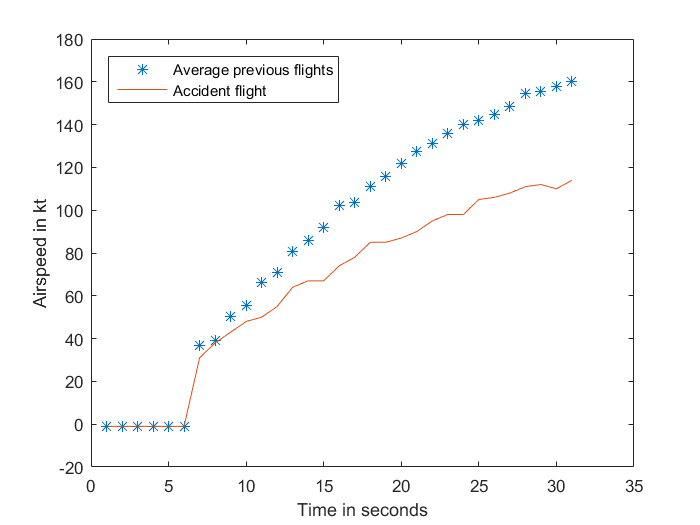
The accident flight take-off data shows a reduced acceleration compared with the previous four flights, but a similar engine RPM. Figure A-1 shows the airspeed of the accident flight and the average of the four previous flights, which were not significantly different from each other.
Figure A-1: Airspeed of accident flight compared to the average of four previous flights
Source: Analysis of aircraft flight data conducted by ATSB
During the take-off run, the aircraft accelerates against rolling resistance of the wheels and aerodynamic drag of the aircraft. The variations of these with velocity are different. Note that the flight data includes airspeed rather than groundspeed. While the groundspeed of the aircraft would have differed from the airspeed, by a number of factors including wind strength and direction, both speeds increase at effectively the same rate and the acceleration is comparable.
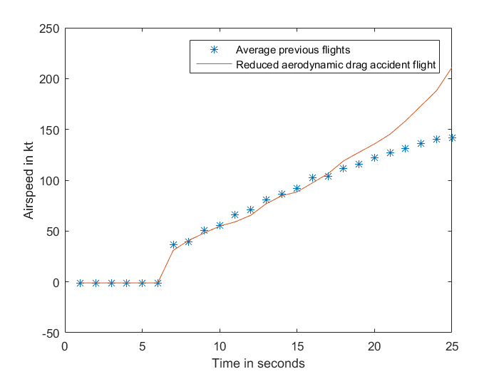
Aerodynamic drag
The aerodynamic drag increases with the square of speed. If the increased drag was primarily aerodynamic, the effect on the airspeed curve would be an increase in the curvature (downwards) as speed increased, after being similar at lower airspeeds. Figure A-2 shows the airspeed from the accident flight with a component of aerodynamic drag removed, and compared to the average previous flights. As can be seen from the graph, this does not reflect a similar acceleration profile to the previous flights. The graph depicts the airspeed showing the commencement of the take-off run, to when the captain rejected the take-off in the accident flight.
Figure A-2: Airspeed of accident flight without an aerodynamic drag component, compared to the average of four previous flights
Source: Analysis of aircraft flight data conducted by ATSB
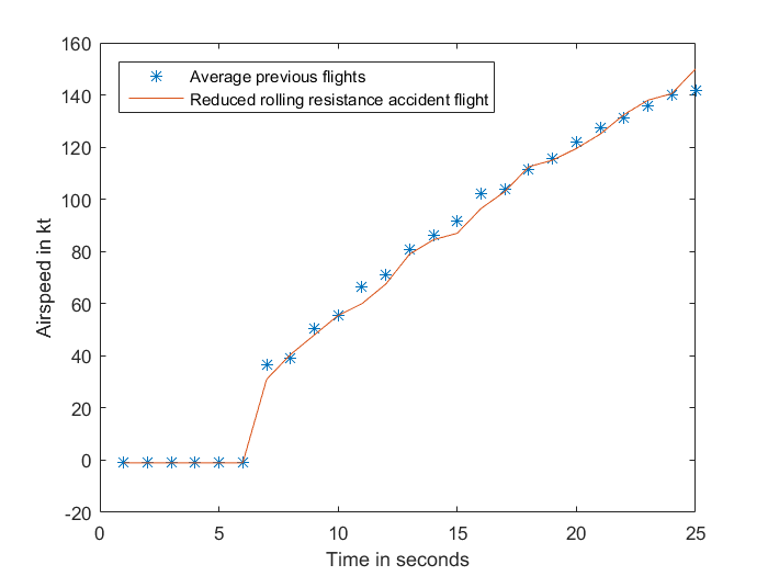
Rolling resistance
The principal components of the rolling resistance are a constant force and a force that varies with rolling speed. If the acceleration was retarded by an increase in rolling resistance, the effect on the airspeed curve would be a general reduction over all airspeeds. This would show a more linear relationship (as depicted in Figure A-3 rather than the curve in Figure A-2).
Assuming, as was evident from the flight data, that the thrust was similar to previous flights, some of the thrust was required to overcome the additional rolling resistance, therefore effectively less thrust was available to accelerate the aircraft.
A correction of an acceleration of 2.5 kt/second as a constant applied to the accident flight is depicted in Figure A-3. As can be seen, the corrected line correlates closely with the average take-off acceleration from the previous four flights. Adding an acceleration component equates to a deceleration (or rolling resistance) component present in the accident flight data. A deceleration component of 2.5 kt/second is 0.13 g.
Figure A-3: Airspeed of accident flight with a reduced rolling resistance component, compared to the average of four previous flights
Source: Analysis of aircraft flight data conducted by ATSB
Rolling coefficient of friction
The rolling coefficient of friction is assumed to be constant with speed and independent of wheel load. The following values (g) have been suggested:[7]
Table 1: Suggested values for rolling coefficient of friction (g)
Runway surface
Rolling coefficient of friction (g)
Hard surface
0.03
Hard turf
0.04
Short grass
0.05
Long grass
0.10
Soft ground
0.10-0.30
From the data in Table 1, a deceleration component of 0.13 g plus the constant for a hard dry runway of 0.03 g equates to a rolling coefficient of friction of about 0.16 g. Therefore, the effect of the rolling resistance force was equivalent to taking off on soft ground.
Failure to rotate
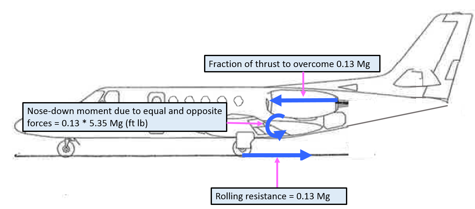
During a normal take-off run, a portion of the thrust equals the rolling resistance. The rolling resistance occurs at the point of contact between the wheels and the runway. The engine thrust occurs through a line parallel to the rolling resistance, at the height of the centre of the engines; the height of the thrust line above the ground for this aircraft is 5.35 ft. An acceleration of 0.13 g on an aircraft of mass M requires a force of 0.13 Mg (Figure A-4). As the thrust line is 5.35 ft above the wheel contact point, it creates a nose-down moment on the aircraft.
Figure A-4: Representation of thrust, rolling resistance and nose-down moment
Source: Aircraft owner – annotated by ATSB
The nose-down moment of the thrust force required to counteract the additional rolling resistance of 0.13 g, is 0.13 Mg x 5.35 (ft lb).[8]
Centre of gravity (CG)
In order for an aircraft to be stable on the ground, the CG is designed to be forward of the main landing gear (otherwise it would tip on its tail). At rotation, a downward force on the tailplane rotates the aircraft about the wheel contact point, raising the aircraft nose and increasing the wing angle of attack. The downward force on the tailplane is produced by an upward deflection of the elevator.
The elevator control power limits the forward CG position of the aircraft. The CG position is conventionally expressed as a per cent mean aerodynamic chord (MAC). According to the Type Certificate Data Sheet for the 550 Bravo, the MAC was 80.98 inches. If the centre of gravity is too far forward, and beyond the design limitation, the elevator will not have sufficient moment to rotate the aircraft.
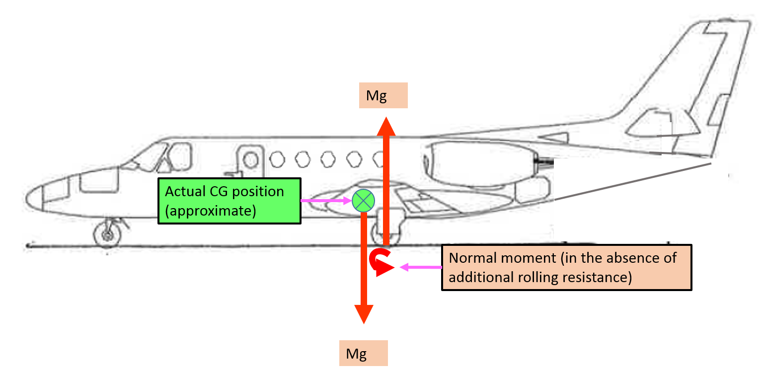
Figure A-5 depicts the normal nose-down moment of the aircraft, in the absence of additional rolling resistance, and the approximate actual CG position for the accident flight.
Figure A-5: Representation of normal nose-down moment and centre of gravity (in the absence of additional rolling resistance)
Source: Aircraft owner – annotated by ATSB
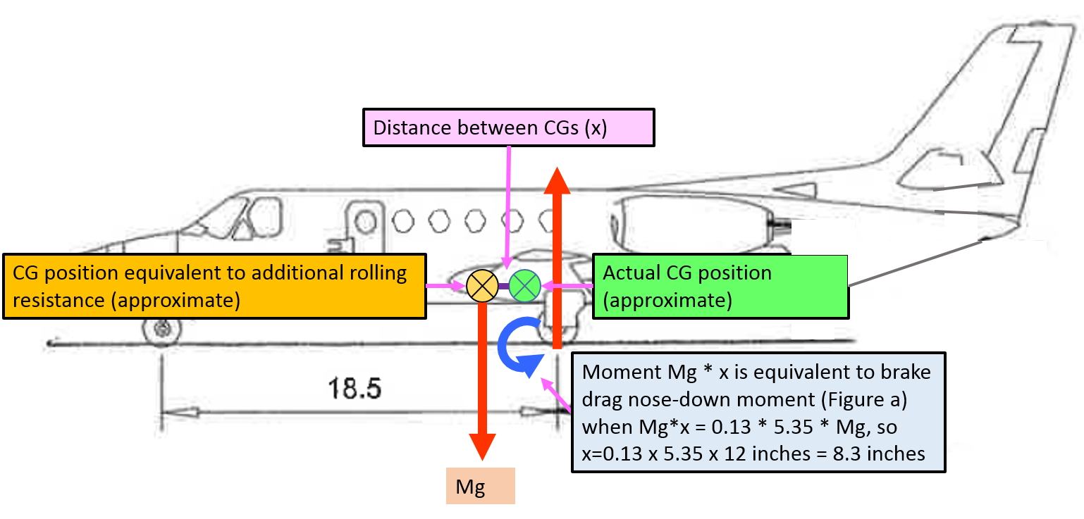
The nose-down moment due to the additional rolling resistance, depicted in Figure A-4, is equivalent to the nose-down moment due to the vertical force (Mg) through a more forward centre of gravity position (Figure A-6). So that 0.13 Mg * 5.35 (ft) * 12 (inches per foot) = Mg * x, where x is the effective forward movement of the CG. Therefore, x is 8.35 inches, which is 10.3% MAC.
Figure A-6: Representation of nose-down moment with additional rolling resistance equivalent to more forward centre of gravity
Source: Aircraft owner – annotated by ATSB
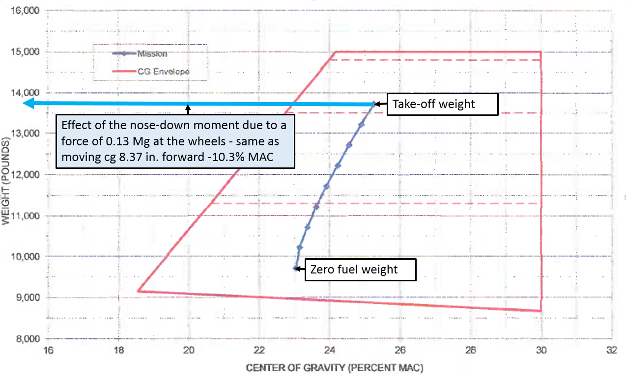
The aircraft’s load sheet the flight crew prepared for the flight is depicted in Figure A-7. The computed CG was 25.1% MAC at take-off. The most forward allowable at that weight was 22% MAC. Moving the centre of gravity forwards 8.35 inches, or 10.3% MAC, would place the effective centre of gravity over 5 inches forward of the allowable range (and off the chart). In that condition it should be impossible to raise the nose of the aircraft – to rotate on take-off.
Figure A-7: Load sheet for VH-FGK showing the accident flight computation of weight and balance from take-off to landing, and the effect of moving the centre of gravity 8.35 inches forward
Source: Aircraft owner – annotated by ATSB
Despite achieving full elevator deflection, at the thrust setting and the airspeed when the captain attempted to rotate the aircraft, it was insufficient to overcome the nose-down moment caused by the additional rolling resistance.
If sufficient rotation could have occurred for the speed that the aircraft achieved (to the necessary angle of attack), the aircraft would have flown (and the wheel rolling resistance would no longer be a factor until landing). In addition, if there were sufficient thrust to continue accelerating the aircraft, at some airspeed it would have lifted off in the ground run attitude, without rotation.
Note that an increase in aerodynamic drag is not only inconsistent with the form of the airspeed curve, but would also not produce the nose-down moment preventing rotation.
Purpose of safety investigations & publishing information
Purpose of safety investigations
The objective of a safety investigation is to enhance transport safety. This is done through:
identifying safety issues and facilitating safety action to address those issues
providing information about occurrences and their associated safety factors to facilitate learning within the transport industry.
It is not a function of the ATSB to apportion blame or provide a means for determining liability. At the same time, an investigation report must include factual material of sufficient weight to support the analysis and findings. At all times the ATSB endeavours to balance the use of material that could imply adverse comment with the need to properly explain what happened, and why, in a fair and unbiased manner. The ATSB does not investigate for the purpose of taking administrative, regulatory or criminal action.
Terminology
An explanation of terminology used in ATSB investigation reports is available here. This includes terms such as occurrence, contributing factor, other factor that increased risk, and safety issue.
Publishing information
Released in accordance with section 25 of the Transport Safety Investigation Act 2003
Ownership of intellectual property rights in this publication
Unless otherwise noted, copyright (and any other intellectual property rights, if any) in this report publication is owned by the Commonwealth of Australia.
Creative Commons licence
With the exception of the Coat of Arms, ATSB logo, and photos and graphics in which a third party holds copyright, this publication is licensed under a Creative Commons Attribution 3.0 Australia licence.
Creative Commons Attribution 3.0 Australia Licence is a standard form licence agreement that allows you to copy, distribute, transmit and adapt this publication provided that you attribute the work.
The ATSB’s preference is that you attribute this publication (and any material sourced from it) using the following wording: Source: Australian Transport Safety Bureau
Copyright in material obtained from other agencies, private individuals or organisations, belongs to those agencies, individuals or organisations. Where you wish to use their material, you will need to contact them directly.
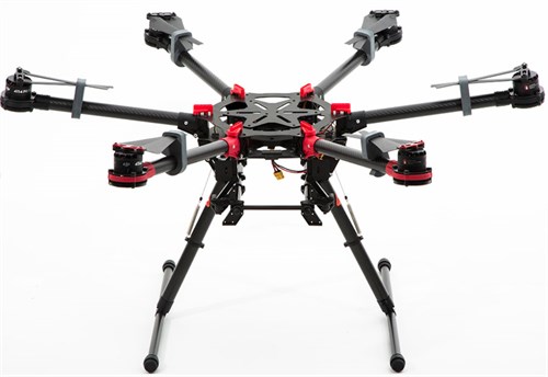
On 19 September 2015, the flight controller of a DJI ‘Spreading Wings’ S900 remotely piloted aircraft (RPA), prepared to conduct aerial photography in Toowoomba, Queensland.
As part of the preparations, the flight controller identified potential hazards associated with the planned operation. The flight was to be conducted over a populated area, and within 3 NM of the Toowoomba aerodrome. The risk assessment included the identification of suitable emergency landing sites for the RPA. The RPA was designed to be capable of flight in the event of one rotor failure, and was also fitted with a parachute. The parachute deploys automatically in certain conditions, and deployment can also be commanded by the flight controller.
The flight controller conducted a daily inspection of the RPA, and found it to be serviceable, including no evidence of damage or cracking to the arms.
Prior to the flight, the flight controller conducted the pre-flight checks and made the appropriate broadcasts on the Toowoomba common traffic advisory frequency (CTAF). The flight controller performed control checks and verified that the controls were working correctly on the ground.
At about 1415 Eastern Standard Time (EST), the flight controller launched the RPA from the rooftop of a nine-storey building. The flight controller again performed control checks, and then commanded the RPA to climb out to the north-northeast. About 30 seconds after becoming airborne, the flight controller heard a loud crack and observed the RPA roll rapidly onto its back. The flight controller commanded the parachute to deploy, but the RPA descended rapidly and collided with the roof of a parked car in the street below.
The RPA was destroyed, the car roof was dented, and no one was injured.
DJI Spreading Wings S900
Source: dji.com
RPA serviceability
The RPA had a total time in service of 10.1 hours prior to the incident flight. Six arm tubes connect the motors to the main frame. The No. 5 arm, constructed of carbon fibre, was fractured, but remained attached to the main frame by the motor cable running through it.
The parachute had deployed and the gas canister used to deploy it was empty, but the parachute did not effectively decelerate the RPA. This was probably due to the RPA being on its back and preventing the parachute from opening properly.
Arm inspection
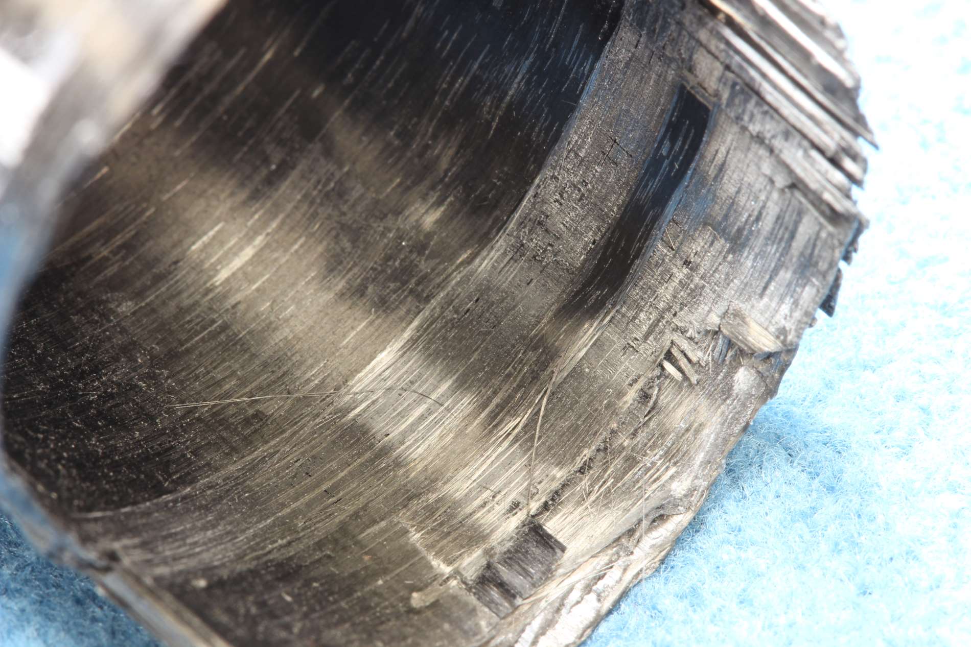
The ATSB conducted a visual inspection of the fractured arm. The arm was primarily comprised of plies of unidirectional carbon fibre tape. The ply orientation alternated between running parallel to the tube length and 90° to the tube length. The outer layer of the tube was woven carbon fabric with a clear gel coat.
Within the unidirectional plies around the fracture site, there were regions where the carbon fibres were not well consolidated or bonded with the resin matrix. Figure 1 shows some of the loose filaments observed on the innermost layer of the tube.
Figure 1: Innermost layer showing loose filaments
Source: ATSB
Distributor comments
The Australian distributor of the DJI S900 advised that their pre-sales testing included the following.
During the process of assembly and configuration of the UAV system, all arms were raised and lowered numerous times.
Upon installation of each arm, each arm was tested individually to ensure correct tension on the arm screws, light horizontal pressure was applied to ensure there is no lateral movement in the arm when it is locked, and to listen for any stress sounds that may emanate from the carbon fibre and/or connecting joints.
The UAV system was tested to ensure proper and consistent functionality of the system. This included flying ‘full stick’ in all directions, and sudden stops.
Australian Certified UAV Operators Incorporated (ACUO) comments
The ACUO advised that they had no known issues regarding motor arm failures of DJI products.
ATSB comment
The ATSB was unable to determine whether or not pre-existing damage was present from prior operation or transit. However, the ATSB identified regions close to the fracture surface where fibres were not well consolidated within the resin. This may have affected the strength of this arm, possibly resulting in the in-flight failure.
The observed lack of bonding between fibre and resin is a result of manufacturing processes and would not have been caused by damage during transport or operation.
Even under maximum loads, the flight tests performed by the distributor may not necessarily identify defects (such as poor bonding between fibre and resin) within the manufactured carbon fibre tube, regardless of whether or not these defects ultimately result in failure. This is because subsurface cracks can propagate unpredictably in fibre composites. Failure can occur at a later time and even when the arm is experiencing loads below its designed maximum.
Despite this, the ATSB is unaware of any other arm failures on this model RPA, indicating that the design and properties of the arms are probably appropriate for the intended application.
Safety message
This incident highlights the importance of appropriate RPA operational controls and procedures. These are particularly important where operations are intended in the vicinity of populous areas or other traffic. The careful application of operational controls and procedures, underpinned by robust risk assessment, is essential as RPA use increases.
Information about remotely piloted aircraft systems (RPAS) is available from the CASA website.
The objective of a safety investigation is to enhance transport safety. This is done through:
identifying safety issues and facilitating safety action to address those issues
providing information about occurrences and their associated safety factors to facilitate learning within the transport industry.
It is not a function of the ATSB to apportion blame or provide a means for determining liability. At the same time, an investigation report must include factual material of sufficient weight to support the analysis and findings. At all times the ATSB endeavours to balance the use of material that could imply adverse comment with the need to properly explain what happened, and why, in a fair and unbiased manner. The ATSB does not investigate for the purpose of taking administrative, regulatory or criminal action.
Terminology
An explanation of terminology used in ATSB investigation reports is available here. This includes terms such as occurrence, contributing factor, other factor that increased risk, and safety issue.
Publishing information
Released in accordance with section 25 of the Transport Safety Investigation Act 2003
Ownership of intellectual property rights in this publication
Unless otherwise noted, copyright (and any other intellectual property rights, if any) in this report publication is owned by the Commonwealth of Australia.
Creative Commons licence
With the exception of the Coat of Arms, ATSB logo, and photos and graphics in which a third party holds copyright, this publication is licensed under a Creative Commons Attribution 3.0 Australia licence.
Creative Commons Attribution 3.0 Australia Licence is a standard form licence agreement that allows you to copy, distribute, transmit and adapt this publication provided that you attribute the work.
The ATSB’s preference is that you attribute this publication (and any material sourced from it) using the following wording: Source: Australian Transport Safety Bureau
Copyright in material obtained from other agencies, private individuals or organisations, belongs to those agencies, individuals or organisations. Where you wish to use their material, you will need to contact them directly.
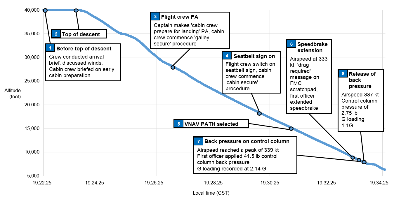
On the evening of 9 May 2015, a Boeing B737-8FE aircraft, registered VH-YID and operated by Virgin Australia Airlines Pty. Ltd. (Virgin), was on a scheduled passenger service from Sydney, New South Wales to Adelaide, South Australia. During a high-speed descent, the crew responded to aircraft indications that they were approaching airspeeds greater than desired by extending the speed brakes. While the speed brakes were still extended, the airspeed continued to increase towards the aircraft’s maximum speed, the result of which would have been an overspeed. In an effort to prevent an overspeed, the first officer overrode the autopilot by pulling back on the control column until the autopilot entered a secondary mode known as control wheel steering‑pitch mode. This was followed immediately by an abrupt release of the control column, after which one cabin crew member sustained a minor injury.
What the ATSB found
The ATSB found that the crew selected a descent speed of 320 kt, which they routinely used for air traffic control-initiated high-speed descents. However, the increased risk of an overspeed in changing wind conditions had not been adequately considered by the crew.
The ATSB also found that, whereas Virgin’s training included a focus on the management of overspeeds, the crew had not yet completed this training. This increased the risk that the guidance provided through other sources would not be followed correctly.
Additionally, the flight crew had initiated the cabin preparation for landing earlier than usual due to the expectation of turbulence later in the descent. This likely reduced the risk of more serious injury to the cabin crew as they were in the final stages of securing the cabin than had they commenced preparations for landing at the normal time.
What's been done as a result
Prior to this occurrence, Virgin had implemented improved crew training and guidance on managing overspeeds. This included the addition of a cyclic simulator training session that focused on overspeed management on descent.
Safety message
This occurrence highlights the increased risk of overspeed when conducting high-speed descents in conditions of varying winds and any associated turbulence. Identifying and discussing the risks associated with high-speed descent increases the likelihood that crew will select a lower descent speed and/or consider the best way to deal with an impending aircraft overspeed before the descent is initiated.
Safety analysis
High-speed descent and potential overspeed
As part of their consideration of the effect of the ‘fairly strong’ winds on the approach, the flight crew discussed the possible effect of turbulence on cabin safety. Similarly, the crew considered the aircraft’s turbulence penetration speed when accepting the high-speed descent. However, the captain recalled that whilst they were aware of changing wind conditions, there was no forecast of severe turbulence, and therefore a descent at 320 kt was considered by the crew to be appropriate. Although likely influenced by the routine use of 320 kt for high-speed descents, the descent at that speed, when the maximum certified limiting speed was 340 kt, increased the risk of an overspeed.
In considering the influences on crew decision making, Orasanu (2010) stated:
What constitutes an appropriate course of action depends on the affordances of the situation. Sometimes a single response is prescribed in company manuals or procedures. At other times, multiple options exist from which one must be selected.
Poor decisions may…arise when a flight crew is aware of conditions that require a decision, but underestimates the level of risk associated with the conditions…Another arises from pilots’ routine experience. If similar…situations have been encountered in the past and a particular course of action has succeeded, the crew will expect to succeed the next time with the same response.
Likewise, Sitkin (1992) as cited in Orasanu (2010) stated that uniformly positive experiences provide no baseline by which to determine when a situation is becoming more dangerous.
The crew reported that selecting 320 kt for a high-speed descent was routine, indicating that this course of action was expected to be successful. Therefore, the likelihood that the crew would consider the risks of an overspeed in this case were harder to identify.
The Flight Safety Foundation (2014) recommended that the pilot monitoring role should include monitoring the aircraft’s flight path and immediately bringing any concern to the pilot flying’s attention. In this case, the captain was monitoring the aircraft’s speed, before focussing on the first officer (FO) as he extended the speed brake and then other operational tasks associated with the descent. Whilst this precluded the captain’s ability to detect the FO’s reaction to an increasing speed trend vector, it was reasonable that the captain felt that the situation was under control.
Orasanu (2010) outlined that the development of expertise contributes to decision making in different ways. This included the development of ‘stored condition-action patterns’, where decision makers interpret a cue pattern as being of a particular type and match it with an action according to a routine (Klein, 1989 and 1993 cited in Orasanu 2010).
In this case, the FO identified an immediate need to prevent an overspeed, and did so by pulling back on the control column and activating control wheel steering-pitch (CWS-P). This had previously been successful for the FO in addressing an impending overspeed, but the difference in this case was that the force required was larger than experienced by the FO in past situations. The flight data recorded a 41 lb back pressure on the FO’s control column with a resulting 2.14 g loading on reversion to CWS‑P. Given the altitude at the time, reversion to CWS-P was considered contrary to Virgin Australia Pty Ltd’s (Virgin) guidance and training in overspeed management. However, the use of the CWS-P mode was reported common among some pilots and, in this case, had possibly become a stored condition-action pattern.
Surprise is a cognitive-emotional response to something unexpected. It results from a mismatch between the individual’s mental expectations and what actually happens around them. Experiencing surprise is a combination of physiological, cognitive and behavioural responses (Rivera and others 2014). If a pilot is not expecting things to go wrong, then the level of surprise can result in taking no action, or the wrong action (Martin 2012).
In this case, the FO reported feeling a ‘pinch’ when CWS-P activated. This, combined with feeling a high g loading, led the FO to abruptly release the amount of back pressure 1 second after its application.
A combination of a sudden increase, followed by a sudden decrease in g loading would have first pushed the occupants of the aircraft towards the floor, followed shortly after by a feeling of weightlessness. This would have increased the difficulty of moving around the cabin and the risk of injury.
Flight management computer data entry procedures
In this occurrence the QNH variation, temperature deviations and descent winds were insufficient to contribute to an inaccurate VNAV PATH construction. In addition, at the time of the occurrence there was no procedural requirement after pre-flight to enter QNH and temperature deviation data, nor to update descent wind data in the descent forecast page of the flight management computer. There was also no guidance on the benefits of entering that data into the computer to produce a more accurate calculated vertical flight path. In some circumstances, the use of pre-flight data would reduce the accuracy of the calculated vertical flight path and result in increased crew workload in managing the energy state of the aircraft.
Training in the management of overspeeds
At the time of the occurrence, Virgin’s Flight Crew Training Manual and other guidance material included information on how to effectively handle an impending overspeed. However, the simulator training session in which crews practiced overspeed management (including on descent) had not been completed by the crew. This simulator session was subsequently completed by all Virgin B737 flight crew, and additional guidance has also been provided.
Early preparation of the cabin for landing
The procedures for preparing the cabin for landing required their commencement no later than FL 200. In this case, the flight crew identified that turbulence on descent may increase the risk of injury to crew and passengers and therefore decided to initiate the cabin preparation at about FL 270. Flight data for the descent showed that this provided an additional 2 minutes before the occurrence for the crew to secure galley equipment and prepare the cabin, including seating all passengers. This reduced the risk of more serious and numerous injuries to the cabin crew and passengers.
Findings
From the evidence available, the following findings are made with respect to the flight path management occurrence involving a Virgin Australia Airlines Pty. Ltd. B737-8FE, registered VH‑YID, on descent into Adelaide Airport, South Australia on 9 May 2015. These findings should not be read as apportioning blame or liability to any particular organisation or individual.
Contributing factors
Although routinely used for high-speed descents, the selected speed for the descent of 320 kt was close the aircraft’s maximum speed of 340 kt and, in combination with the increased headwind as the aircraft descended through about 8,000 ft, increased the risk of an overspeed.
After identifying the unexpected rapid increase in airspeed, the first officer applied sufficient back pressure on the control column to override the autopilot with the intention of avoiding the impending overspeed. This increased the g loading on the aircraft to an extent where safely walking in the cabin would be difficult.
In response to feeling the increased g loading, the first officer abruptly released the back pressure on the control column, resulting in a sudden pitch change and reduced g loading that led to the cabin crew member losing their footing and sustaining a knee injury.
Other factors that increased risk
The Virgin Australia Airlines Pty. Ltd. procedures did not require flight crew to update the QNH, temperature deviation or the descent winds in the flight management computer after departure. In some circumstances, this would reduce the accuracy of the calculated flight path and increase crew workload in managing the aircraft’s energy state.
At the time of the occurrence, the Virgin Australia Airlines Pty. Ltd. training included a focus on the management of overspeeds. However, the associated simulator training session had not been completed by the crew, increasing the risk that they would not react in accordance with the published operational guidance material.
Other findings
The earlier-than-usual preparation of the cabin for landing meant that, at the time of the occurrence, the cabin crew were in the final stages of that activity. This reduced the risk of more serious and numerous injuries to the cabin crew and passengers.
The occurrence
On the evening of 9 May 2015, a Boeing B737-8FE aircraft, registered VH-YID and operated by Virgin Australia Airlines Pty. Ltd. (Virgin) as ‘Velocity 436’, was on a scheduled passenger service from Sydney, New South Wales to Adelaide, South Australia. The first officer (FO) was the pilot flying.[1]
At about 1915 Central Standard Time[2], the flight crew conducted an approach briefing in preparation for the descent. The crew discussed the ‘fairly strong’ westerly wind forecast in the area that would affect their descent, and decided they would instruct the cabin crew to prepare the cabin for landing at about flight level (FL) 270[3]. This was reported slightly earlier than usual and was intended to reduce the risk of turbulence-related injuries. Soon after, air traffic control (ATC) requested the crew to conduct a high-speed descent into Adelaide, which the crew accepted. The FO changed the planned descent speed from 280 kt to 320 kt, which was reported by the crew to be routinely used during ATC-initiated high-speed descents.
The descent was commenced about 4 minutes later and, passing about FL 270, the captain made the public address ‘cabin crew prepare for landing’. This was the cue for the cabin crew to commence the cabin preparation procedure by securing all loose cabin equipment, ensuring passengers were in their seats with seatbelts fastened and then securing themselves in their jump seats. Seven minutes later the flight crew switched the seatbelt signs on, as a cue to the cabin crew to finalise this procedure and take their seats.
During the descent the FO controlled the aircraft’s vertical profile using various autopilot descent modes. Passing through FL 250, the FO selected the VNAV PATH mode (see the section titled VNAV PATH descent mode).
As the aircraft passed through 10,000 ft, the airspeed started to increase above 320 kt and at 8,400 ft the message ‘drag required’ displayed on the flight management computer (FMC) scratchpad as per system design. In response, the FO extended the speed brake, making an effort to do so slowly and smoothly. The captain observed this action, initially concerned that the FO may extend the speed brake too quickly. However, the captain was satisfied that the speed brake was appropriately extended and that the increasing airspeed trend was being managed. The captain’s attention was then turned to other tasks. Over the next 6 seconds the airspeed continued to increase, and the FO recalled seeing the speed trend vector on the primary flight display (PFD) extend beyond the aircraft’s maximum certified speed (VMO).[4]
In an effort to avoid an overspeed, the FO pulled back forcibly on the control column in order to raise the nose, overriding the autopilot and activating the control wheel steering – pitch (CWS-P). This technique was routinely used to manage overspeeds on descent. On this occasion the FO reported feeling greater than usual resistance when raising the nose due to the already low pitch angle. The FO then recalled feeling a ‘pinch’ as the autopilot reverted to CWS-P, along with a sudden pitch change and a high g loading[5] on the aircraft. In response, the FO abruptly released the back pressure on the control column, rapidly unloading the g loading. At that moment, the cabin crew had almost completed securing the cabin and were about to take their seats. They reported experiencing what they thought to be turbulence, and two cabin crew in the rear galley lost their footing. This resulted in one of the cabin crew impacting the galley floor heavily, sustaining an injury to their knee.
The FO stowed the speed brake, selected the LVL CHG (level change) descent mode and reduced the selected speed to 250 kt. The captain checked the status of the cabin crew and was informed of the injury to the crew member.
The sequence of events during the descent is highlighted in Figure 1.
Figure 1: Sequence of events on descent, including the flight and cabin crew actions plotted against altitude and time
Source: ATSB
Personnel information
The flight crew signed on for duty in Sydney at 0900 Eastern Standard Time[6] and had been on duty for 11 hours at the time of the occurrence.
The captain held an Air Transport Pilot (Aeroplane) Licence and had a total flying experience of 13,500 hours, of which about 8,750 were on the B737 aircraft. The captain commenced flying with Virgin in 2003 and held a valid Class 1 Aviation Medical Certificate.
The FO held an Air Transport Pilot (Aeroplane) Licence and had a total flying experience of about 7,500 hours, of which about 5,000 were on the B737 aircraft. The FO commenced flying with Virgin in 2007 and held a valid Class 1 Aviation Medical Certificate. Although the FO reported feeling tired at the time of the occurrence, there was no additional evidence to indicate a level of fatigue known to affect performance beyond what would reasonably be experienced at the end of the day.
Aircraft information
VNAVPATH descent mode
VNAV PATH is an automated descent mode primarily designed to keep the aircraft on a predetermined descent path using aircraft pitch. During descents in this mode, airspeed is controlled using thrust or displaying messages to the flight crew to increase drag as required. The VNAV PATH mode allows for minor airspeed excursions while prioritising keeping the aircraft on path. If airspeed increases to 10 kt above the selected speed, the message ‘drag required’ appears on the FMC scratchpad. In response, crew extend the speed brake to arrest further speed increases.
Control wheel steering – pitch (CWS-P)
Pushing a CWS engage switch on the mode control panel engages the autopilot (A/P) pitch and roll axes in the CWS mode. At the time of the occurrence, CWS‑P could also be engaged by applying 40 lb back pressure to the control column to manually override the A/P. By doing so, a desired pitch attitude could be set. The ability to manually engage CWS‑P and override the A/P was later removed from the flight control computer’s software to avoid inadvertent and undetected reversion from a descent mode to CWS‑P. With CWS‑P engaged, the A/P manoeuvres the aircraft in response to control pressures applied by either pilot. The control pressure is similar to that required for manual flight. When control pressure is released, the A/P holds the existing attitude.
While the FO’s routine use of CWS-P as a means to manage overspeeds was not part of Virgin training, it was reported used by the FO and other pilots. This was because it was an effective way to handle an overspeed on descent without disconnecting the A/P, particularly when changing weather conditions meant that an overspeed could occur with little time for the crew to react.
Maximum operating indicated airspeed
The maximum operating indicated airspeed (VMO) represents the maximum certified limiting speed of the aircraft. VMO for the B737-8FE is 340 kt. An overspeed warning sounds if the aircraft exceeds VMO.
Airspeed trend vector on the primary flight display
The primary flight display (PFD) presents a dynamic colour display of the parameters necessary for flight path control. This includes (Figure 2):
the manually-selected airspeed
a green speed trend vector, which indicates predicted airspeed in 10 seconds time
the VMO.
Figure 2: B737 PFD, showing the manually-selected airspeed (number 1), the green speed trend vector (number 2) and VMO (number 4). Note VMO gradually reduces below 340kt with increasing altitude above approximately FL250. In this graphic, the representation shows the aircraft at FL380 (38,000 ft), explaining the reduced VMO
Source: B737 Flight Crew Operations Manual and Wikipedia, modified by the ATSB
Effect of g loading
G loading refers to the aircraft occupant experiencing an apparent acceleration equal to the load factor times the acceleration due to gravity. For example, when the pilot performs a pull up with a load factor of two, loose objects fall to the floor at twice the normal acceleration of gravity. A g loading less than one results in feelings of reduced weight and, eventually, loose objects floating upwards once the g loading reduces below zero.
Meteorological information
The forecast meteorological information that was available to the crew included:
an Aerodrome Forecast for arrival into Adelaide that predicted a light south‑westerly wind and showers of rain with intermittent periods of less than 30 minutes of south-westerly winds at 20 kt, gusting up to 30 kt
winds from 264 °M at 54 kt at FL 350, from 250 °M at 38 kt at FL 250, from 258°M at 40 kt at FL 150 and from 270° at 41 kt at 5,000ft.
Recorded data
The flight data was examined to derive the aircraft’s computed airspeed (CAS) and the wind affecting the descent as they pertain to the crew’s actions. This examination showed the following:
By 10,468 ft in the descent the aircraft reached the selected descent speed of 320 kt. Over the next 30 seconds, as the aircraft descended to 8,136 ft (when the speed brake was extended) the headwind increased from 30 to 39 kt, and the airspeed increased from 320 to 333 kt.
Over the next 5 seconds, as the aircraft descended from 8,136 ft to 7,790 ft, the headwind increased from 39 to 48 kt, and the airspeed increased from 333 to a peak of 339 kt. At this point the back pressure on the FO’s control column was recorded as 41.5 lb, and CWS-P engaged with a peak g loading of 2.14 g.
One second later the back pressure on the FO’s control column reduced to 2 lb, consistent with a release of the back pressure, with a minimum g loading of 0.066.
The speed brake was stowed about 10 seconds later at 7,492 ft.
Training and guidance in overspeed management
The following overspeed management training and guidance was provided to flight crew:
B737-NGFlight Crew Training Manual content. ‘Crews routinely climbing or descending in windshear conditions may wish to consider a 5 to 10 knot reduction in climb or descent speeds to reduce overspeed occurrences…During climb or descent, if VNAV or LVL CHG pitch control is not correcting the overspeed satisfactorily, switching to the V/S [vertical speed] mode temporarily may be helpful in controlling speed.’ The cruise section of the manual also stated that ‘there have been reports of passenger injuries due to over‑controlling the airplane during high altitude, high airspeed flight when overriding the control column with the autopilot engaged…’.
High- and low-speed briefing document(valid from February to July 2015). ‘High speed descents need to be managed carefully when operating near areas of steep wind gradients or expected turbulence…Reducing speed prior to entering areas of large wind change is the best technique...It is preferable to accept a temporary overspeed (provided it is not excessive or sustained) rather than a breach of altitude or large abrupt control inputs at high altitude...’. The document also recommended ‘the momentary use of V/S if other modes are not correcting the overspeed.’ and that ‘CWS P may be required but must be applied smoothly with small inputs at high altitude. Speed brake use is also recommended to assist recovery in the cruise.’
Recurrent simulator training program on overspeed events. Guidance to crew for the simulator session on overspeed events stated that ‘use of VNAV PATH with high descent speeds…is not recommended in turbulent conditions or areas of steep wind velocity changes’. This simulator session had not been completed by either flight crew member at the time of the occurrence.
Procedures for FMC updates – wind data, QNH and temperature deviations
The B737 Flight Management Computer System Reference Manual (2015) stated that‘the descent forecasts page [on the FMC] enables the pilot to enter descent wind data to more accurately define the descent path and allow for varying conditions’. It also outlined that ‘ISA DEV’ (the temperature deviation from the international standard atmosphere standard (ISA)[8]) and QNH[9] can be manually entered. The ability to enter QNH and temperature deviation is designed to increase the accuracy of the VNAV PATH construction by the FMC, as it allows the FMC to compensate for deviations from ISA QNH and temperature values at sea level.
Virgin’s Flight Crew Operating Manual documented that during the pre-flight procedure, pilots enter ‘initial data’ and ‘navigation data’ into the FMC. This included entering three of the four available predicted descent winds from the flight plan. These four winds included at FL 350, FL 250 and FL 150 and 5,000 ft. The three selected winds were entered into the descent forecast page.
If an aircraft is fitted with an aircraft communications addressing and reporting system (ACARS), wind data can be automatically uploaded into the FMC once the flight plan has been loaded during pre-flight duties. This also facilitates receipt of updated descent wind information if requested. At the time of the occurrence, Virgin’s procedures did not include updating descent winds in flight or a requirement to enter the temperature deviation and QNH. The captain reported that if there is a ‘really strong’ head or tailwind at the top of descent, the crew may decide to amend the FMC top of descent point (either earlier or later) and use the VNAV SPD vertical mode[10].
In this occurrence, the flight plan wind information was generated 3 hours and 10 minutes before the scheduled arrival time. The aircraft was fitted with ACARS, however updated descent wind data was not requested and the temperature deviation and QNH were not entered before approaching Adelaide. This was not inconsistent with the then Virgin procedures.
Procedures for securing the cabin before landing
The procedures for securing the cabin on descent were documented in the Virgin Flight Crew Operating Manual and Standard Operating Procedures. The following is a summary of those procedures:
Not below FL 200, the pilot monitoring (PM) makes the public address ‘cabin crew prepare for landing.’ In response, the cabin crew commence the ‘galley secure’ actions including stowing all galley items, switching off equipment such as ovens and securing all latches. About 10 minutes is provided for cabin crew to complete these actions.
Around transition (10,000 ft), flight crew select the fasten seatbelt sign ON, which triggers cabin crew to complete the ‘cabin procedure’ actions. This includes ensuring that all passengers have their seatbelts fastened, their seat backs upright and that any cabin baggage is stowed. These actions take about 1 minute.
Related occurrences
Overspeed occurrences on descent
Between 2012 and 2015, 51 occurrence reports were submitted to the ATSB that involved an overspeed in a B737 aircraft on descent. Of these, two occurred during high-speed descents. Of the other occurrences, three reported the use of CWS-P This included investigation AO‑2012‑138 below.
The crew of a Boeing 737-800 aircraft was conducting a flight from Adelaide, South Australia to Canberra, Australian Capital Territory. Just prior to commencing descent, ATC cleared the aircraft to conduct a high-speed descent. The aircraft descended below the 7,000 ft altitude clearance limit and, after being alerted to this by ATC, the flight crew climbed the aircraft back to 7,000 ft and continued the approach to land. The ATSB found that the combination of auto-flight system mode changes (including inadvertent use of CWS‑P) and the management of the airspeed during the descent resulted in a high workload environment. This occurrence highlighted the need to continually monitor descent profiles and airspace limitations in relation to the aircraft’s position.
Purpose of safety investigations & publishing information
Purpose of safety investigations
The objective of a safety investigation is to enhance transport safety. This is done through:
identifying safety issues and facilitating safety action to address those issues
providing information about occurrences and their associated safety factors to facilitate learning within the transport industry.
It is not a function of the ATSB to apportion blame or provide a means for determining liability. At the same time, an investigation report must include factual material of sufficient weight to support the analysis and findings. At all times the ATSB endeavours to balance the use of material that could imply adverse comment with the need to properly explain what happened, and why, in a fair and unbiased manner. The ATSB does not investigate for the purpose of taking administrative, regulatory or criminal action.
Terminology
An explanation of terminology used in ATSB investigation reports is available here. This includes terms such as occurrence, contributing factor, other factor that increased risk, and safety issue.
Publishing information
Released in accordance with section 25 of the Transport Safety Investigation Act 2003
Ownership of intellectual property rights in this publication
Unless otherwise noted, copyright (and any other intellectual property rights, if any) in this report publication is owned by the Commonwealth of Australia.
Creative Commons licence
With the exception of the Coat of Arms, ATSB logo, and photos and graphics in which a third party holds copyright, this publication is licensed under a Creative Commons Attribution 3.0 Australia licence.
Creative Commons Attribution 3.0 Australia Licence is a standard form licence agreement that allows you to copy, distribute, transmit and adapt this publication provided that you attribute the work.
The ATSB’s preference is that you attribute this publication (and any material sourced from it) using the following wording: Source: Australian Transport Safety Bureau
Copyright in material obtained from other agencies, private individuals or organisations, belongs to those agencies, individuals or organisations. Where you wish to use their material, you will need to contact them directly.
During the landing as the main wheels touched down, the aircraft began to shudder severely and pulled to the right. All attempts by the pilot to regain directional control were unsuccessful and the aircraft ran off the side of the runway. After entering the lightly grassed flight strip, the turning effect increased, and the aircraft began to slide sideways.
The abnormal side loadings imposed during the slide caused the left main landing gear to collapse. The investigation found that a substantial amount of the threaded section of the nut which secures the right main landing gear torque link tie bolt had stripped allowing the two halves of the torque link to separate. The right main wheel assembly was then free to oscillate up to ninety degrees to the direction of travel as the landing loads were applied. The pilot was not able to apply enough steering control to overcome the effects of the oscillations. The investigation also found that the left and right main landing gear torque links were installed incorrectly. The left set was fitted to the right landing gear and vice versa.
This incorrect fitment had the effect of placing excessive tension loads on the link shear nut assembly causing it to fail by stripping the nut threads. Furthermore, neither of the torque link tie bolt assemblies were of the type specified by the manufacturer for this torque link installation. The bolts and shear castellated nuts were of the type used with the original torque links fitted to this aircraft model. The design of the original torque links was significantly different to the modified type fitted to the accident aircraft. With the original links, all torque stresses were borne against the mating surfaces of the link halves and the tie bolt assembly carried only shear loads. The later modified links require the tie bolt to carry some of the torque loads in tension.
The incorrect fitment of the failed torque links caused a substantial increase in the normal tension loads on the tie bolt assembly. The shear nut and link bolt assembly was not able to withstand these additional tension loads. In July 1986 the Australian Department of Aviation issued an Airworthiness Directive (AD) based on information contained in the manufacturers Service Bulletin (SB) 746A.
The AD required operators to inspect all aircraft models which were not fitted with the torque link replacement kit called for in SB 746A. This AD also recommended that the replacement kit be fitted at the earliest opportunity. Subsequent to the issue of the Australian AD the manufacturer issued two updates to the SB 746A as SB 746B dated 11 June 1991 and SB 746C dated 15 September 1992. SB 746B required the replacement of the torque link connecting nut and bolt to prevent the original shear nut from stripping. The Australian AD had not been revised to reflect the later information contained in SB 746B and SB 746C. SB 746C required the inspection of the torque links for cracks within ten hours.
If any cracks were found the torque links were to be replaced with torque link kit 765-155 revision G before further flight. If no cracking was detected the links were to be replaced within the next 100 hours of operation. Both SB 746B and SB 746C stated that "compliance is critical". The accident aircraft met compliance with the Australian AD but not with the SB 746 parts B or C. The aircraft logbooks indicated that the modified torque links were probably fitted to the aircraft prior to July 1990 when it was imported into Australia.
Three other aircraft of the same type were inspected during the initial stages of the investigation, and it was found that they met compliance with the manufacturers original SB 746A as required in the Australian AD but not SB 746 parts B or C. The investigation was unable to obtain a current, appropriately amended manufacturer's Maintenance Manual or Illustrated Parts Catalogue for this aircraft type that would show the correct method of fitment for the modified torque links.
The manufacturer's Australian distributor indicated that the only way such instructions and illustrations could be obtained was for the operators to purchase a total kit number 765-155 revision G which included fitment details. Several local maintenance organisations and operators stated that they had been unable to procure appropriate updated amendments for their Maintenance Manuals or Illustrated Parts Catalogues for several years.
The same situation was said to apply to the amendment service for Service Bulletins and Service Instructions. In each case where the torque links were fitted incorrectly or where the shear nut assembly was still in service the operator or maintenance organisation was not in receipt of either SB 746B or SB 746C.
SAFETY ACTION
As a result of the investigation the Bureau made the following interim recommendation IR930188 to the Civil Aviation Authority on 24 August 1993. It stated:
The Bureau recommends that the Civil Aviation Authority:
1. initiate inspections of all aircraft to ensure compliance with Aerostar Service Bulletin 746C;
2. amend AD/TSA-600/33 Amendment 4 to reflect the latest issue of Aerostar Service Bulletin 746C; and
3. assess revisions to manufacturers data which are quoted in Australian Airworthiness Directives and determine the requirements for subsequent amendment to the relevant Airworthiness Directive.
[The Bureau had previously recommended similar action. BASI Report B/913/1009, VH-TPM, Recommendation 1 refers].
In response to this recommendation, the Civil Aviation Authority Published Airworthiness Directive AD/TSA-600/33 Amendment 5 effective 15 September 1994.
However, this Airworthiness Directive amendment did not require compliance with Aerostar Service Bulletin SB 746C which the aircraft manufacturer classifies as "compliance critical" and that SB 746C "supersedes and voids SB 746, SB 746A and SB 746B".
In further correspondence with the Civil Aviation Authority the Bureau requested a further review of the Airworthiness Directive to ensure that it accurately reflects the aircraft manufacturers compliance requirements. The Civil Aviation Authority's response to this correspondence stated in part:
"This Authority does not agree with your assessment of amendment 5 to AD TSA-600-33".
The Bureau has classified this response as CLOSED/NOT ACCEPTED.
The aircraft was being flown by a student conducting solo circuit practice. During the ground roll following the second landing the pilot lost directional control of the aircraft. The aircraft ran off the right of the runway into soft ground and turned through 90 degrees before coming to rest against a ditch. The propeller and nose gear received damage.
The pilot had been operating from the slightly soft strip for several hours, with a 15 knot crosswind. He was using brake, as well as rudder, to keep the aircraft straight in the crosswind. The pilot had changed direction of take off so that one brake was not overused, but found that if he took off to the West, he encountered unacceptable turbulence, so he resumed easterly take-offs.
At about 50 knots during the accident take off, the left brake failed and the pilot lost directional control. The aircraft ground looped off the runway, causing the landing gear to collapse.
During the landing roll the aircraft steering could not be controlled by the steering tiller. The tiller continued to drive to the full left position and directional control could only be maintained by differential braking. When the aircraft was stopped the nosewheel and tiller were locked in the full left position and taxiing was not possible. While arrangements were being made to disembark the passengers on the runway, the steering suddenly freed itself and the aircraft was then taxied to the terminal. The steering system could not be faulted on the ground at Albury but the nosewheel steering shut-off valve was changed as a precaution. The aircraft then operated the return flight to Sydney, but the problem recurred. The nosewheel steering control valve was changed and no further problems have been reported.
The aircraft was on final approach to land at night. At approximately 150 feet above the ground, it suddenly rolled to the left and a loud bang was heard.
The pilot applied full opposite aileron and rudder and was able to level wings prior to touchdown.
Investigation showed that the left "flap down" cable had snapped, allowing the left flap to retract rapidly while the right hand flap remained fully extended.
The right hand "flap down" cable was subsequently found to be corroded internally and failed on test even though it appeared serviceable.